

Page 1

Cisco Physical Security Multiservices Platform Series User Guide
Model CPS-MSP-1RU-K9
Model CPS-MSP-2RU-K9
Americas Headquarters
Cisco Systems, Inc.
170 West Tasman Drive
San Jose, CA 95134-1706
USA
http://www.cisco.com
Tel: 408 526-4000
800 553-NETS (6387)
Fax: 408 527-0883
Text Part Number: OL-21838-03
Page 2

NOTICE. ALL STATEMENTS, INFORMATION, AND RECOMMENDATIONS IN THIS MANUAL ARE BELIEVED TO BE ACCURATE BUT ARE PRESENTED
WITHOUT WARRANTY OF ANY KIND, EXPRESS OR IMPLIED. USERS MUST TAKE FULL RESPONSIBILITY FOR THEIR APPLICATION OF ANY PRODUCTS.
THE SOFTWARE LICENSE AND LIMITED WARRANTY FOR THE ACCOMPANYING PRODUCT ARE SET FORTH IN THE INFORMATION PACKET THAT
SHIPPED WITH THE PRODUCT AND ARE INCORPORATED HEREIN BY THIS REFERENCE. IF YOU ARE UNABLE TO LOCATE THE SOFTWARE LICENSE
OR LIMITED WARRANTY, CONTACT YOUR CISCO REPRESENTATIVE FOR A COPY.
The Cisco implementation of TCP header compression is an adaptation of a program developed by the University of California, Berkeley (UCB) as part of UCB’s public
domain version of the UNIX operating system. All rights reserved. Copyright © 1981, Regents of the University of California.
NOTWITHSTANDING ANY OTHER WARRANTY HEREIN, ALL DOCUMENT FILES AND SOFTWARE OF THESE SUPPLIERS ARE PROVIDED “AS IS” WITH
ALL FAULTS. CISCO AND THE ABOVE-NAMED SUPPLIERS DISCLAIM ALL WARRANTIES, EXPRESSED OR
LIMITATION, THOSE OF MERCHANTABILITY, FITNESS FOR A PARTICULAR PURPOSE AND NONINFRINGEMENT OR ARISING FROM A COURSE OF
DEALING, USAGE, OR TRADE PRACTICE.
IN NO EVENT SHALL CISCO OR ITS SUPPLIERS BE LIABLE FOR ANY INDIRECT, SPECIAL, CONSEQUENTIAL, OR INCIDENTAL DAMAGES, INCLUDING,
WITHOUT LIMITATION, LOST PROFITS OR LOSS OR DAMAGE TO DATA ARISING OUT OF THE USE OR INABILITY TO USE THIS MANUAL, EVEN IF CISCO
OR ITS SUPPLIERS HAVE BEEN ADVISED OF THE POSSIBILITY OF SUCH DAMAGES.
Cisco and the Cisco Logo are trademarks of Cisco Systems, Inc. and/or its affiliates in the U.S. and other countries. A listing of Cisco's trademarks can be found at
www.cisco.com/go/trademarks. Third party trademarks mentioned are the property of their respective owners. The use of the word partner does not imply a partnership
relationship between Cisco and any other company. (1005R)
Cisco Physical Security Multiservices Platform Series User Guide
Copyright © 2010 Cisco Systems, Inc. All rights reserved.
IMPLIED, INCLUDING, WITHOUT
Page 3

CONTENTS
Preface v
Overview v
Organization v
Obtaining Documentation, Obtaining Support, and Security Guidelines vi
CHAPTER
CHAPTER
1 Overview 1-1
Important Safety Information 1-1
Multiservices Platform Series Products 1-1
System Interface 1-2
Control Panel Buttons and LEDs 1-2
Hard Drive Indicator LEDs 1-3
Rear Panel 1-4
2 Setting Up and Maintaining the Multiservices Platform Series Device 2-1
Setting up a Multiservices Platform Series Device 2-1
Unpacking the Multiservices Platform Series Device 2-2
Mounting the Multiservices Platform Series Device in a Rack 2-2
Preparing for Rack Mounting 2-3
Rack Mounting 2-4
Installing Hard Drives 2-10
Connecting to Power, the Network, and External Devices 2-11
Multiservices Platform Series Maintenance Operations 2-11
Removing the Chassis Cover 2-11
Replacing a System Fan 2-12
Replacing a Power Supply 2-13
Checking Air Flow 2-14
APPENDIX
APPENDIX
OL-21838-03
A System Specifications A-1
General Specifications A-1
Power Supply Specifications A-2
B Recovering from a Hard Drive Failure B-1
Replacing a Hard Drive B-3
Cisco Physical Security Multiservices Platform Series User Guide
iii
Page 4

Contents
Reimaging a Multiservices Platform Series Device that is Running VSM B-5
Reimaging a Multiservices Platform Series Device that is Running Cisco IPICS B-6
Reimaging a Multiservices Platform Series Device that is Running Cisco PAM B-7
APPENDIX
APPENDIX
APPENDIX
C Fiber Channel Card C-1
D 16 x CIF / 4 x 4CIF Video Capture Card D-1
Video Inputs D-1
Power and System Requirements D-2
E 16 x D1 and 8 x D1 Video Capture Cards E-1
Before You Begin E-1
Overview E-2
Requirements E-3
Features E-4
Encoding Parameter Limitations E-4
Motion Detection with Low Quality Cameras E-5
Video Card Connector and LED E-6
Understanding Video Channel Numbers E-6
1-RU Multi Services Platform Series Device Channel Numbers E-6
2-RU Multi Services Platform Series Device Channel Numbers E-8
APPENDIX
I
NDEX
iv
Connecting the Video Capture Card to the BNC Breakout Panel E-10
Part Numbers E-12
Specifications E-13
Configuration Instructions for Cisco Video Surveillance E-14
Configuring Camera Channel Numbers in Cisco VSM E-14
Connecting and Configuring Analog PTZ Cameras E-14
Troubleshooting PTZ Camera Controls E-19
Related Documentation E-19
F Using IPMI to Remotely Reboot a Multi Services Platform Series Device F-1
Setting Up IPMI on Multi Services Platform Device F-1
Rebooting a Multi Services Platform Series Device by using the IPMI F-2
Cisco Physical Security Multiservices Platform Series User Guide
OL-21838-03
Page 5

Overview
Preface
This document describes how to install the Cisco Multiservices Platform Series devices and how to
perform the initial set up of these devices. It provides information for the following Multiservices
Platform Series model:
• CPS-MSP-1RU-K9—1-rack unit (RU) chassis with motherboard, 300 W power supply, and CPU.
(Drives and option cards are available separately.)
• CPS-MSP-2RU-K9—2-rack unit (RU) chassis with motherboard, 900 W power supply, and CPU.
(Drives are available separately.)
This document it is intended for experienced system integrators and technicians who are installing these
devices.
Organization
This document is organized as follows:
Chapter 1, “Overview” Provides information about the Multiservices
Chapter 2, “Setting Up and Maintaining the
Multiservices Platform Series Device”
Appendix A, “System Specifications” Provides technical specifications for the
Appendix B, “Recovering from a Hard Drive
Failure”
Appendix C, “Fiber Channel Card” Provides information about the optional fiber channel
Platform Series features, chassis, and system
interface
Describes how to perform a variety of set up and
hardware maintenance procedures for Multiservices
Platform Series devices
Multiservices Platform Series, including connection
ports, power needs and operating environment
requirements
Describes how to replace and reimage a failed hard
disk drive
card, which enables fibre channel connectivity to
external storage arrays
OL-21838-03
Cisco Physical Security Multiservices Platform Series User Guide
v
Page 6

Preface
Appendix D, “16 x CIF / 4 x 4CIF Video
Capture Card”
Appendix E, “16 x D1 and 8 x D1 Video
Capture Cards”
Appendix F, “Rebooting a Multi Services
Platform Series Device by using the IPMI”
Provides information about the optional 16 x CIF / 4
x 4CIF video capture card, which enables capturing
and compressing analog video streams
Provides information about the optional 16 x D1 and
8 x D1 video capture cards, which capture and
compress standard definition analog video streams
how to configure a Multiservices Platform Series
device so that it can be rebooted by using the IPMI,
and how to perform the remote reboot procedure
Obtaining Documentation, Obtaining Support, and Security Guidelines
For information about obtaining documentation, submitting a service request, and gathering additional
information, see the monthly What’s
revised Cisco
http://www.cisco.com/en/US/docs/general/whatsnew/whatsnew.html
Subscribe to the What’s New in Cisco Product Documentation as a Really Simple Syndication (RSS) feed
and set content to be delivered directly to your desktop using a reader application. The RSS feeds are a free
service and Cisco currently supports RSS version 2.0.
technical documentation, at:
New in Cisco Product Documentation, which also lists all new and
vi
Cisco Physical Security Multiservices Platform Series User Guide
OL-21838-03
Page 7

CHAP T E R
1
Overview
The Cisco Multiservices Platform Series models are high-performance servers that offer choices for
deploying and managing physical security applications, including video surveillance, access control, and
flexible incident response communications. Applications include:
• Video surveillance with network digital recording and playback
• Physical access control with electronic access control using the IP network to manage doors and
locks
• Incident response systems for on-demand communications across multiple agencies
This chapter includes these sections:
• Important Safety Information, page 1-1
• Multiservices Platform Series Products, page 1-1
• System Interface, page 1-2
• Rear Panel, page 1-4
Important Safety Information
To prevent potential serious injury to yourself and others and to protect your Multiservices Platform
Series device, make sure to read and understand in the compliance, safety, statutory, and related in
formation information in Regulatory Compliance and Safety Information for the Cisco Multiservices
Platform Series before you set up, install, or operate the device.
Multiservices Platform Series Products
The Cisco Multiservices Platform Series comprises a suite of server platforms that offer choices for a
variety of Cisco physical security applications.
The Multiservices Platform Series includes the following models:
• 1-RU Multiservices Platform Series, Model CPS-MSP-1RU-K9—Supports up to four 1 TB SATA
hard drives.
• 2-RU Multiservices Platform Series, model CPS-MSP-2RU-K9—Supports six or twelve 2 TB SATA
hard drives.
Cisco Physical Security Multiservices Platform Series User Guide
OL-21838-03
1-1
Page 8
System Interface
Key features include:
• 300 W high-efficiency power supply on 1-RU model, and 900 W high-efficiency power supply with
redundancy option on 2-RU model
• High-performance fans with built-in redundancy for optimized cooling
• Support for fiber channel card or video encoding card (1-RU only)
• Hot-swappable SATA hard disk drives (in RAID configurations only)
System Interface
The Multiservices Platform Series device includes a variety of controls and LED indicators that help you
manage and monitor the system. The following sections describe these items in detail:
• Control Panel Buttons and LEDs, page 1-2
• Hard Drive Indicator LEDs, page 1-3
Chapter 1 Overview
Control Panel Buttons and LEDs
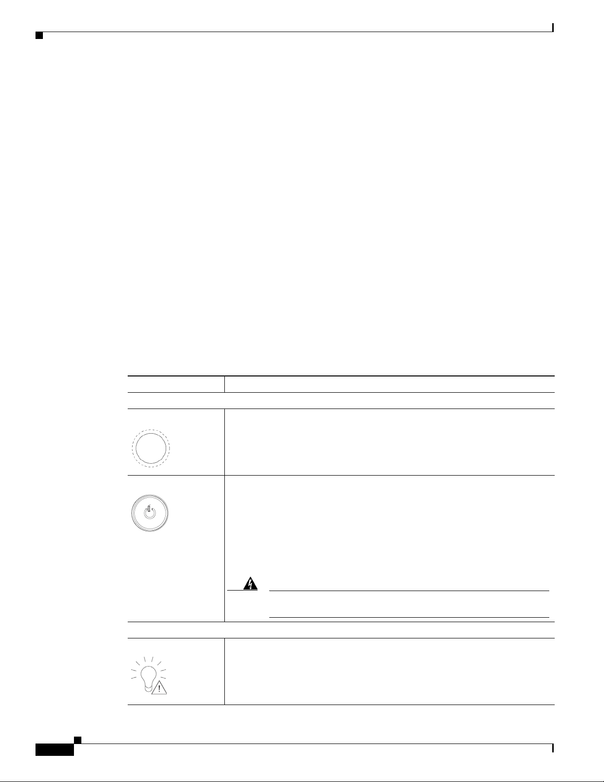
Table 1-1 describes the controls and LEDs on the front panel of the Multiservices Platform Series device.
Ta b l e 1-1 Multiservices Platform Series Device Controls and LEDs
Control Description
Buttons
Reset button Press this button to reboot the Multiservices Platform Series device.
This button is recessed on 2-RU models. Use a pin or paperclip to press it on
these devices.
Power button Press this button to apply or remove power from the Multiservices Platform
Series device.
To perform a normal, graceful shutdown of the device, press and release the
button quickly. To shut down the device immediately, press and hold the button
for 4 seconds.
Turning off system power with this button removes the main power but keeps
standby power supplied to the system.
Warning
Because the device receives standby power even when it is turned
off, unplug device from its power source before servicing it.
1-2
LEDs
Power Failure LED Flashes to indicate a power failure in the power supply.
Cisco Physical Security Multiservices Platform Series User Guide
OL-21838-03
Page 9
Chapter 1 Overview
System Interface
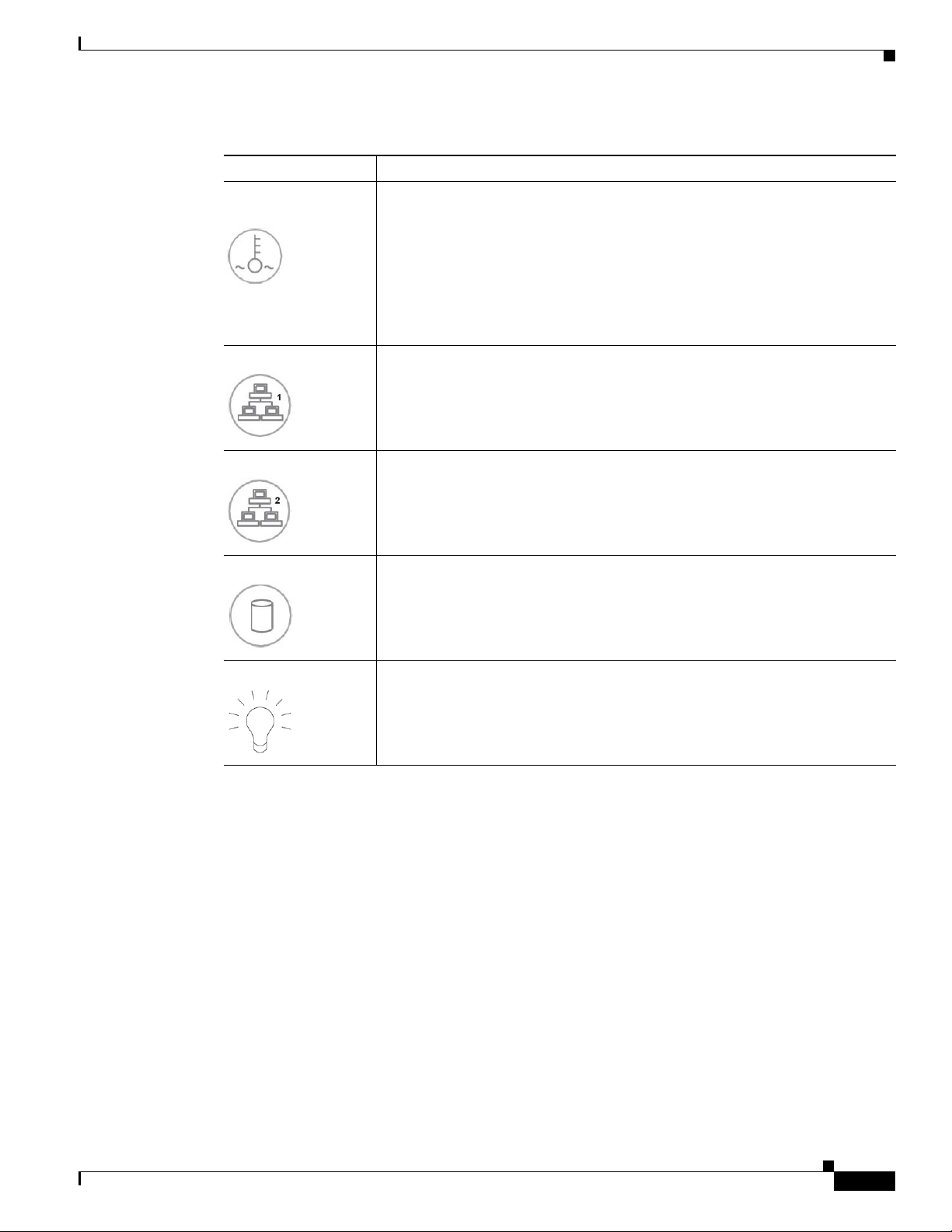
Table 1-1 Multiservices Platform Series Device Controls and LEDs (continued)
Control Description
Overheat/Fan Fail
LED
NIC 1 LED Flashes to indicate network activity on network interface card (NIC) 1.
NIC 2 LED Flashes to indicate network activity on network interface card (NIC) 2.
Flashes to indicate a fan failure. Lights continuously to indicate an overheat
condition.
An overheat condition can be caused by cables or other obstructions that
constrict the airflow in the system or by the ambient room temperature being
too warm. If this condition occurs, check the routing of the cables, make sure
that all fans are installed and operating normally, make sure that the chassis
covers are installed, and verify that the heat sinks are installed properly. For
related information, see the
“Checking Air Flow” section on page 2-14.
HDD LED Lights to indicate hard disk drive activity.
Power LED Lights when the Multiservices Platform Series device power supply receives
Hard Drive Indicator LEDs
The hard drive bays on the Multiservices Platform Series device include these LED indicators:
• 1-RU model:
–
Solid green—Normal drive status
–
Flashing green—Normal drive activity
–
Solid red—Drive failure
–
Flashing red—Drive rebuilding
• 2-RU model:
power.
This LED should be lit during normal system operation.
OL-21838-03
–
Sold blue—Normal drive status
–
Flashing blue—Normal drive activity
–
Solid red—Drive failure
Cisco Physical Security Multiservices Platform Series User Guide
1-3
Page 10
Rear Panel
Rear Panel
Chapter 1 Overview
–
Flashing red—Drive rebuilding
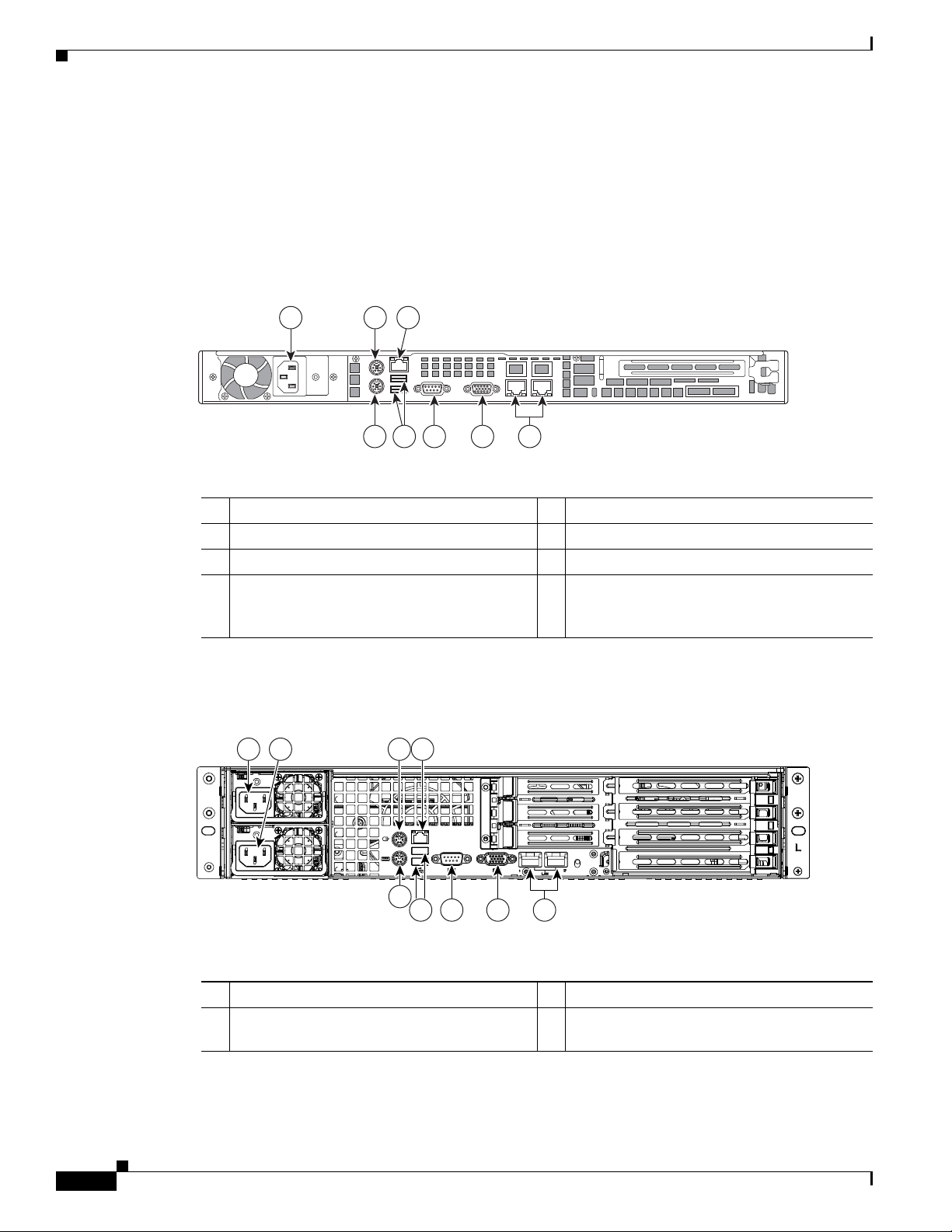
Figure 1-1 illustrates the rear panel of the Multiservices Platform Series 1-RU model.
Figure 1-1 Multiservices Platform Series 1-RU Model Rear Panel
1 2
3
8 56
7
4
1 Power cord connector port. 5 VGA (video) monitor port.
2 Mouse port. 6 Serial port.
3 Diagnostic port, for Cisco TAC use. 7 USB ports.
4 RJ-45 Ports for network connection. The port
8 Keyboard port.
on the left is the first network port and the port
on the right is the second.
Figure 1-2 illustrates the rear panel of the Multiservices Platform Series 2-RU model
Figure 1-2 Multiservices Platform Series 2-RU Model Rear Panel
2
1 3 4
277891
1-4
9
1 Power cord connector port. 6 VGA (video) monitor port.
2 (Optional) Power cord connector port on
redundant power supply.
Cisco Physical Security Multiservices Platform Series User Guide
198718
678
5
7 Serial port.
OL-21838-03
Page 11

Chapter 1 Overview
Rear Panel
3 Mouse port. 8 USB ports.
4 Diagnostic port, for Cisco TAC use. 9 Keyboard port.
5 RJ-45 Ports for network connection. The port
on the left is the first network port and the port
on the right is the second.
OL-21838-03
Cisco Physical Security Multiservices Platform Series User Guide
1-5
Page 12

Rear Panel
Chapter 1 Overview
1-6
Cisco Physical Security Multiservices Platform Series User Guide
OL-21838-03
Page 13

CHAP T E R
2
Setting Up and Maintaining the Multiservices Platform Series Device
This chapter describes how to perform a variety of set up and hardware maintenance procedures for the
the Multiservices Platform Series device.
Setting up a device includes unpacking it, mounting it in a rack, installing hard drives if needed, and
connecting it to power, the network, and external devices.
Maintenance procedures that you may need to perform for a Multiservices Platform Series device
include replacing a fan or power supply and checking air flow around the device.
This chapter includes these sections:
• Setting up a Multiservices Platform Series Device, page 2-1
• Multiservices Platform Series Maintenance Operations, page 2-11
Setting up a Multiservices Platform Series Device
When you receive a Multiservices Platform Series device, you should perform the following general
set-up steps in this order:
1. Unpack the device and verify the package contents.
2. Mount the device in a rack.
3. Install hard drive, if necessary
4. Connect the device to power, the network and external devices.
Then, see your physical security application documentation for information about installing the
application and configuring the device.
For detailed information, see the following sections:
• Unpacking the Multiservices Platform Series Device, page 2-2
• Mounting the Multiservices Platform Series Device in a Rack, page 2-2
• Installing Hard Drives, page 2-10
• Connecting to Power, the Network, and External Devices, page 2-11
OL-21838-03
Cisco Physical Security Multiservices Platform Series User Guide
2-1
Page 14

Chapter 2 Setting Up and Maintaining the Multiservices Platform Series Device
Setting up a Multiservices Platform Series Device
Unpacking the Multiservices Platform Series Device
A Multiservices Platform Series device ships in one or two boxes, depending on the model and number
of hard drives that your ordered:
• 1-RU model—Ships in one box that contains the chassis with hard drives preinstalled.
• 2-RU model—Ships in two boxes. One box contains the chassis and one box contains from 4 to 12
hard drives.
To unpack the Multiservices Platform Series device, follow these steps:
Procedure
Step 1 If your shipment includes two boxes, make sure that the serial number that is printed on the shipping
label on each box is the same.
Caution If the serial numbers are not identical, contact Cisco or your Cisco partner before you set up the system.
Setting up a Multiservices Platform Series device with mismatched components prevents the system
from operating.
Step 2 Carefully open each shipping box and remove its contents.
Step 3 Make sure that the box in which the chassis shipped includes these items:
• Rail assemblies for rack mounting
• Operating system license and activation packet (if applicable)
• Envelope that contains the following:
–
Getting Started with Cisco Video Surveillance Manager Products
–
Recovery disk
–
End user license and warranty information disk
–
One or two power cables (if ordered).
–
Screws and washers for rack mounting
Mounting the Multiservices Platform Series Device in a Rack
The Multiservices Platform Series device is designed to be installed in a standard 19-inch rack. The
server ships with a pair of rail assemblies.
This chapter describes how to rack mount the Multiservices Platform Series device. It includes these
sections:
2-2
• Preparing for Rack Mounting, page 2-3
• Rack Mounting, page 2-4
Note Some figures in this chapter show sample hardware and devices. The procedures are similar for all
models.
Cisco Physical Security Multiservices Platform Series User Guide
OL-21838-03
Page 15

Chapter 2 Setting Up and Maintaining the Multiservices Platform Series Device
Preparing for Rack Mounting
Before you install the Multiservices Platform Series device in a rack, review the following guidelines:
Choosing a Location
• Leave enough clearance in front of the rack to enable you to open its front door completely
(approximately 25 inches).
• Leave approximately 30 inches of clearance in back of the rack to allow for sufficient air flow and
ease of servicing.
• The Multiservices Platform Series device is intended for installation in a restricted access location,
such as a dedicated equipment room or service closet.
Rack Precautions
• Ensure that the leveling jacks on the bottom of the rack are extended to the floor with the full weight
of the rack resting on them.
• In a single rack installation, attach stabilizers to the rack.
• In a multiple rack installation, couple the racks to each other.
Setting up a Multiservices Platform Series Device
• Make sure that the rack is stable before extending a component from the rack.
• Extend only one component from a rack at a time. Extending two or more components may cause
the rack to become unstable.
General Precautions
• Review the electrical and general safety precautions that come with the components that you add to
your chassis.
• Determine the placement of each component in the rack before you install the rails.
• Install the heaviest components on the bottom of the rack first, then work up.
• Use a regulating uninterruptible power supply (UPS) to protect a device from power surges and
voltage spikes and to keep the device operating if a power failure occurs.
• Close the front door of the rack and all panels and components on the servers when not servicing
them to maintain proper cooling.
Rack Mounting Considerations
• Make sure to install the Multiservices Platform Series device in an environment that is within the
rated operating temperature and humidity range (see
Appendix A, “System Specifications”). If the
Multiservices Platform Series device is installed in a closed or multi-unit rack assembly, be aware
that the ambient operating temperature of the rack environment may be greater than the ambient
temperature of the room.
• Make sure that there is sufficient air flow for safe operation of the Multiservices Platform Series
device.
• The Multiservices Platform Series device should be mounted in a rack so that a hazardous condition
does not arise due to uneven mechanical loading.
• Consider the connection of equipment to the power supply circuitry and the effect that possible
overloading of circuits may have on overcurrent protection and power supply wiring. Consider
equipment nameplate ratings when addressing this issue.
OL-21838-03
• Maintain a reliable ground. The rack itself should be grounded. Pay particular attention to power
supply connections other than direct connections to the branch circuit (for example, power strips).
Cisco Physical Security Multiservices Platform Series User Guide
2-3
Page 16
Setting up a Multiservices Platform Series Device
1
3
4
5
2
Rack Mounting
This section describes how to install the Multiservices Platform Series device in a rack by using the
quick release mounting system. This system provides a quick, convenient, and secure method for rack
mounting the Multiservices Platform Series device.
The Multiservices Platform Series device includes two rail assemblies. One is designed for the left side
of the chassis and one is designed for the right side. Each rail assembly consists of an inner chassis rail
that attaches to the chassis, an outer rail that attaches to a rack, and a middle rail that extends from the
outer rail. Each inner rail includes a locking tab, which prevents the server from unintentionally coming
completely out of the rack when you pull it out for servicing or access.
Installing the Multiservices Platform Series device in a rack by using the quick release mounting system
involves these steps. The following sections describe each step in detail.
• Installing Square Hole to Round Hole Adapters (Optional), page 2-5
• Releasing the Inner Rails, page 2-6
• Attaching the Inner Rails to the Multiservices Platform Series Device, page 2-7
• Attaching the Outer Rails to a Rack, page 2-8
• Placing the Multiservices Platform Series Device in the Rack, page 2-9
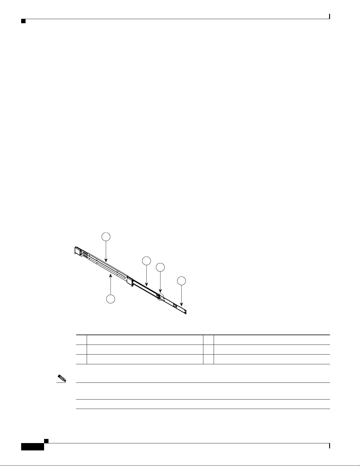
Before you attach the rack rails, see Figure 2-1 to become familiar with the rail components assembly.
This figure shows the left rail assembly, which attaches to the left side of the Multiservices Platform
Series device.
Chapter 2 Setting Up and Maintaining the Multiservices Platform Series Device
Figure 2-1 Identifying the Rail Assembly Components (Left Rail Assembly Shown)
1 Outer rail 4 Inner rail locking tab
2 Outward-facing side of outer rail 5 Inner rail
3 Middle rail
Note There are a variety of racks available. The procedure for your rack may be slightly different than the
following instructions. Refer to the installation instructions for your rack for additional information.
.
Cisco Physical Security Multiservices Platform Series User Guide
2-4
OL-21838-03
Page 17
Chapter 2 Setting Up and Maintaining the Multiservices Platform Series Device
Installing Square Hole to Round Hole Adapters (Optional)
The quick release mounting system on the Multiservices Platform Series 2-RU model is designed for
racks with square holes. If you want to use this system with a round hole rack or a threaded hole rack
(with thread size M5 or larger), you can do so by using the square hole to round hole adapter set. This
set includes four brackets, which attach to the front and rear of the right and left rack rails and provide
square holes to which you can attach the quick release rack rails.
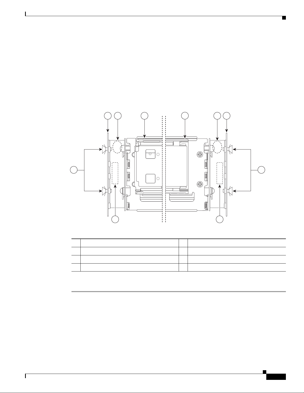
To install the square hole to round hole adapters, see Figure 2-2 and perform the procedure that follows.
This figure shows how the brackets and rails attach to the left side of a rack.
Figure 2-2 Attaching Square Hole to Round Hole Adapters
Setting up a Multiservices Platform Series Device
1 2
AB
3
4
5 6
77
INWARD
INWARD
277796
8 8
1 Left front of rack 5 Rear bracket, labeled B
2 Front bracket, labeled A 6 Left rear of rack
3 Front of left rack rail 7 M5 x 12 screws for securing adapters
4 Rear of left rack rail 8 Inward stamp, must be facing inward
OL-21838-03
Procedure
Step 1 Identify the two brackets that are labeled A and take these actions for each bracket:
a. Place one of the brackets inside of the rack and align the holes in the bracket with the holes on the
front of the rack at the height where you want to install the Multi Service Platform.
Make sure that the “Inward” stamp on the bracket faces toward the inside of the rack.
b. Attach the bracket to the rack using two M5 x 12 screws, provided.
Drive the screws through the rack and then into the bracket. Make sure to securely tighten the
screws.
Cisco Physical Security Multiservices Platform Series User Guide
2-5
Page 18

Setting up a Multiservices Platform Series Device
Step 2 Identify the two brackets that are labeled B and take these actions for each bracket:
a. Place one of the brackets inside of the rack and align the holes in the bracket with the holes on the
rear of the rack at the same height that you installed the “A” brackets.
Make sure that the “Inward” stamp on the bracket faces toward the inside of the rack.
b. Attach the bracket to the rack using two M5 x 12 screws, provided.
Drive the screws through the rack and then into the bracket. Make sure to securely tighten the
screws.
Releasing the Inner Rails
You must release the inner rails before you can attach them to the Multiservices Platform Series device.
To do so, see
Figure 2-3 Extending and Releasing the Inner Rail (Left Rail Assembly Shown)
Chapter 2 Setting Up and Maintaining the Multiservices Platform Series Device
Figure 2-3 and perform the procedure that follows.
2-6
196331
Procedure
Step 1 Pull the inner rail out until it is fully extended.
Step 2 Press the inner rail locking tab down.
Step 3 Remove the inner rail from the rail assembly.
Step 4 Repeat these steps for the other inner rail.
Cisco Physical Security Multiservices Platform Series User Guide
OL-21838-03
Page 19
Chapter 2 Setting Up and Maintaining the Multiservices Platform Series Device
Attaching the Inner Rails to the Multiservices Platform Series Device
There are two inner rails. One attaches to each side of the Multiservices Platform Series device.
To attach the inner rails to the Multiservices Platform Series device, see Figure 2-4 and perform the
procedure that follows.
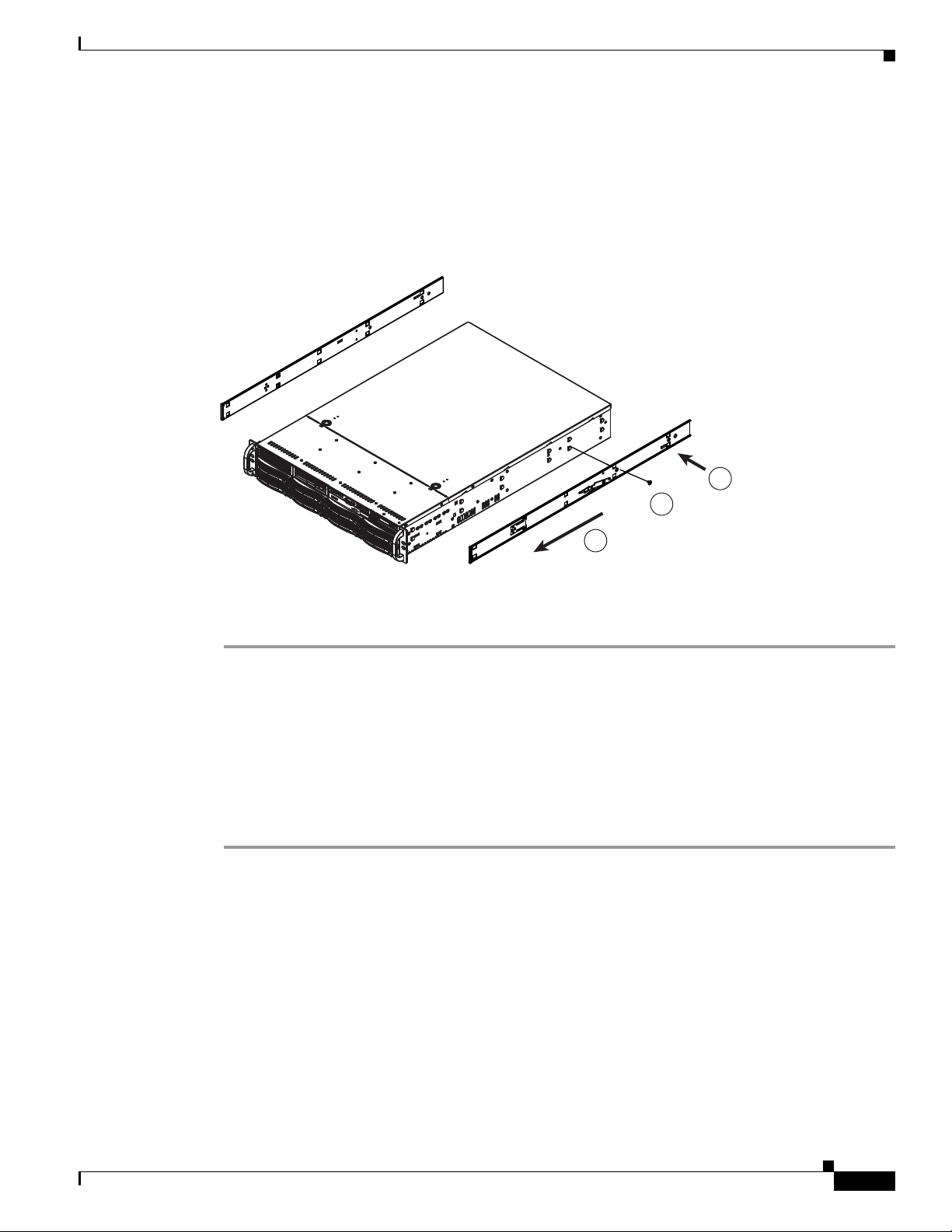
Figure 2-4 Installing the Inner Rails
Setting up a Multiservices Platform Series Device
1
3
2
196332
Procedure
Step 1 Place an inner rail firmly against a side of the Multiservices Platform Series device, aligning the hooks
on the side of the device with the holes in the inner rail.
Make sure to use the correct (left or right) inner rail.
Step 2 Slide the inner rail toward the front of the Multiservices Platform Series device until the inner rail clicks
into the locked position.
Step 3 Secure the inner rail to the Multiservices Platform Series device by using one of the M4 x 6L screws,
provided.
Step 4 Repeat Step 1 through Step 3 for the other inner rail.
OL-21838-03
Cisco Physical Security Multiservices Platform Series User Guide
2-7
Page 20
Setting up a Multiservices Platform Series Device
2
1
3
4
196333
Attaching the Outer Rails to a Rack
There are two outer rack rails. One attaches to each side of the rack and connects to the inner rack rails
to hold the Multiservices Platform Series device in place. Each outer rack rail adjusts to fit racks between
26.5 and 36.4 inches (67.31 and 92.5 cm) deep.
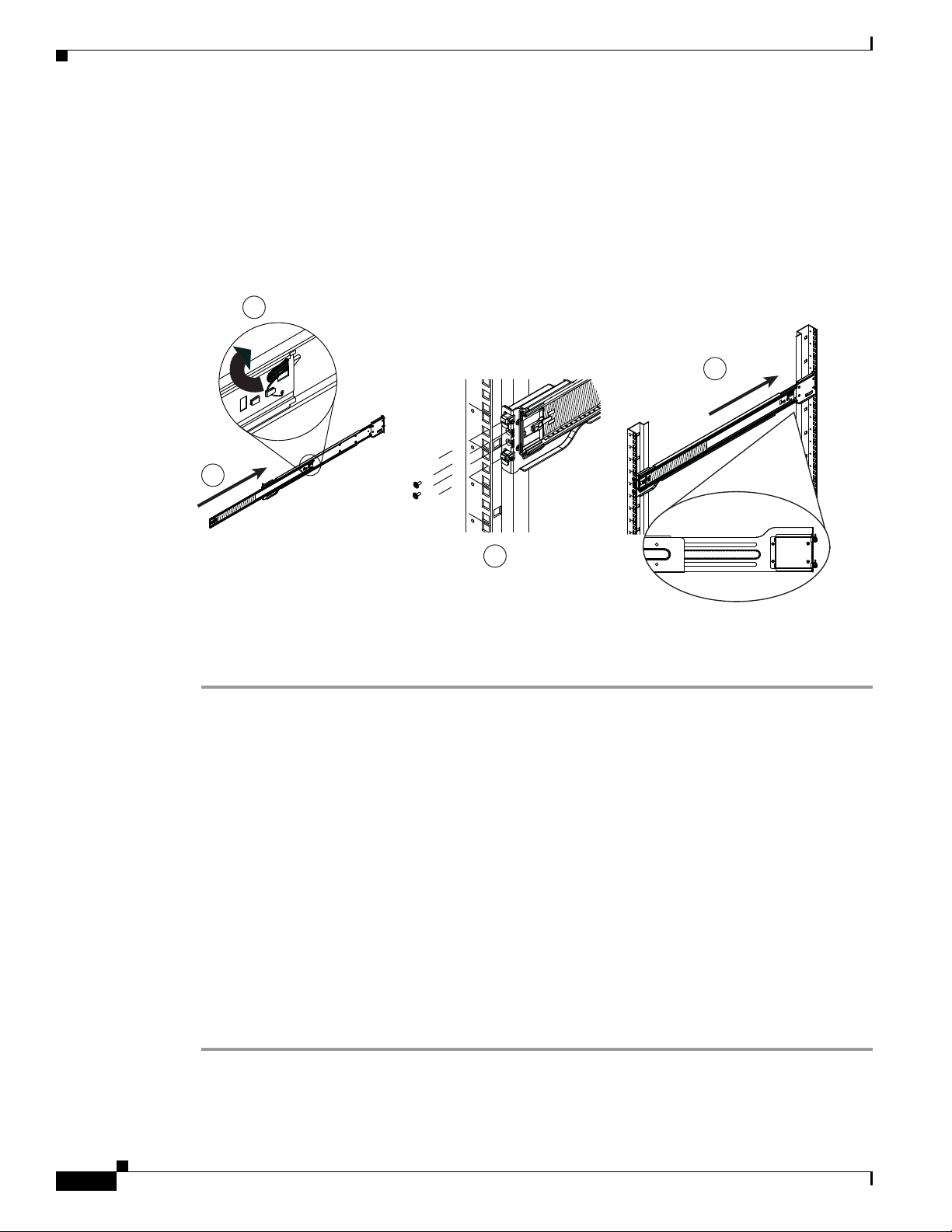
To attach the outer rails to a rack, see Figure 2-5 and perform the procedure that follows.
Figure 2-5 Attaching Outer Rails to a Rack (Left Outer Rail Shown)
Chapter 2 Setting Up and Maintaining the Multiservices Platform Series Device
Procedure
Step 1 Press up the locking tab at the rear of the middle rail.
Step 2 Push the middle rail into the outer rail.
Step 3 Hang the hooks on the front of the outer rail onto the slots on the front of the rack.
If you are using the square hole to round hole adapter set, hang the outer rail hooks onto the brackets
that you installed. (See the
“Installing Square Hole to Round Hole Adapters (Optional)” section on
page 2-5 for related information.)
Step 4 Secure the front of the outer rail to front of the rack by using one of the M5 x12L screws and washers,
provided.
Step 5 Pull out the rear of the outer rail until and hang the hooks on the rear of the outer rail onto the slots on
the rear of the rack.
If you are using the square hole to round hole adapter set, hang the outer rail hooks onto the brackets
that you installed.
Step 6 Secure secure the front of the outer rail to front of the rack by using one of the M5 x12L screws and
washers, provided.
Step 7 Repeat Step 1 through Step 5 for the other outer rail.
2-8
Cisco Physical Security Multiservices Platform Series User Guide
OL-21838-03
Page 21
Chapter 2 Setting Up and Maintaining the Multiservices Platform Series Device
Placing the Multiservices Platform Series Device in the Rack
To place the Multiservices Platform Series device in a rack, see Figure 2-6 and perform the procedure
that follows.
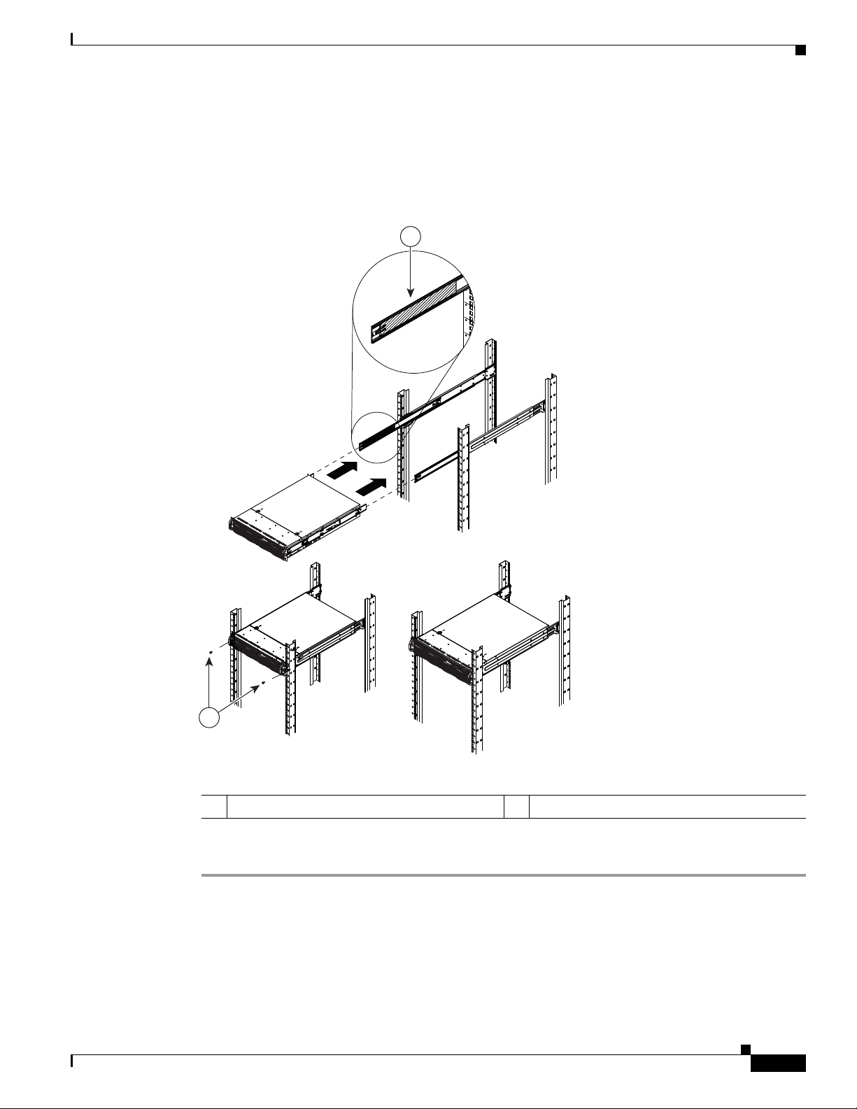
Figure 2-6 Placing the Server in a Rack
1
Setting up a Multiservices Platform Series Device
OL-21838-03
2
196334
1 Ball-bearing shuttle 2 Screws
Procedure
Step 1 Confirm that the inner and outer rack rails are properly installed on the Multiservices Platform Series
device and on the rack.
Step 2 Pull the middle rail out from the front of the outer rail until the ball-bearing shuttle is at the front locking
position of the middle rail.
Step 3 Align the inner rails that are attached to the Multiservices Platform Series device with the front of the
middle rails that are attached to the rack.
Cisco Physical Security Multiservices Platform Series User Guide
2-9
Page 22

Setting up a Multiservices Platform Series Device
Step 4 Slide the inner rails into the middle rails, keeping even pressure on each side, until the locking tab of the
inner rail clicks into the front of the middle rail.
The server is now locked into the fully extended position.
Step 5 Simultaneously press each locking tab (see Figure 2-3) and push the server all the way to the rear of the
rack
Step 6 (Optional) Use M5 x 20L-T screws to secure the server handles to the front of the rack.
To remove the Multiservices Platform Series device from the rack, pull it out from the rack until the inner
rail is fully extended, press each inner rail locking tab down (see
from the rack.
To remove an outer rail from the rack, remove the screws that attach it to the rack (if you used these
screws), depress the black outer rail locking tabs that protrude through the front and rear rack mounting
holes, lift the rail so its hooks are free from the mounting holes, and slide the rail pieces together so that
you can remove from the rack.
Chapter 2 Setting Up and Maintaining the Multiservices Platform Series Device
Figure 2-3), then remove the server
Installing Hard Drives
If you ordered a Multiservices Platform Series 2-RU model, you must install the hard drives that you
ordered for the system.
If you are installing six drives in a Multiservices Platform Series 2-RU chassis, install the drives in the
left six slots as you face the front of the chassis. You can install drives in any order and into any available
slot.
Caution When installing hard drives for the first time, make sure that each hard drive includes a label with a serial
number that is identical to the serial number of the Multiservices Platform Series chassis. Setting up a
Multi Services Platform with mismatched hard drives prevents the system from operating.
To install hard drives, follow these steps:
Procedure
Step 1 Press the red handle-release button on the front of the hard drive.
The drive handle extends from the front of the hard drive.
Step 2 With the red handle-release button of the hard drive facing toward you and to the right, push the drive
straight into an open slot on the front of the Multiservices Platform Series chassis until you feel
resistance.
Step 3 Push the drive handle toward the hard drive until the handle locks into place.
Step 4 Repeat these steps until each hard drive is installed.
2-10
Tip You may find it easiest to install the drives from the top down and from the right to the left. This
approach allows the drives to slide into the slots more easily.
Cisco Physical Security Multiservices Platform Series User Guide
OL-21838-03
Page 23

Chapter 2 Setting Up and Maintaining the Multiservices Platform Series Device
Multiservices Platform Series Maintenance Operations
Connecting to Power, the Network, and External Devices
After you mount the Multiservices Platform Series device in a rack and install the hard drives, you are
ready to connect a monitor, keyboard, and mouse to the server, and to connect the server to power and
to your network. To make these connections, follow these steps:
Procedure
Step 1 Connect a monitor, keyboard, and mouse to the appropriate ports on the back of the Multiservices
Platform Series device.
Step 2 Connect a Category 5 or higher network cable to either network port on the back of the Multiservices
Platform Series device and to your network switch.
Step 3 Take either of these actions to connect power to the Multiservices Platform Series device:
• If your Multiservices Platform Series device is configured with one power supply, connect the
provided power cable to the power port on the back of the device, then plug the cable into an
electrical outlet.
• If your Multiservices Platform Series device is configured with two power supplies, connect the two
provided power cables to the two power ports on the back of the device, then plug each cable into
an electrical outlet.
Multiservices Platform Series Maintenance Operations
The following sections describe various maintenance operations that you may need to perform. For
information about replacing a hard drive, see
• Removing the Chassis Cover, page 2-11Figure 2-6
• Replacing a System Fan, page 2-12
• Replacing a Power Supply, page 2-13
• Checking Air Flow, page 2-14
Removing the Chassis Cover
You must remove the chassis cover before installing internal fans and before performing various
maintenance operations.
To remove the chassis cover, press and hold each release tab on the top of the chassis cover, slide the
chassis cover toward the rear of the device, and lift it off. See
Note This figure illustrates a sample model. The procedure is similar on all models.
Caution Except for a short time, do not operation the Multiservices Platform Series device with the chassis cover
removed. The chassis cover must be in place to allow proper air flow and prevent overheating.
Appendix B, “Recovering from a Hard Drive Failure.”
Figure 2-7.
OL-21838-03
Cisco Physical Security Multiservices Platform Series User Guide
2-11
Page 24

Multiservices Platform Series Maintenance Operations
Figure 2-7 Removing the Chassis Cover
Chapter 2 Setting Up and Maintaining the Multiservices Platform Series Device
To replace the chassis cover, slide the chassis cover toward the front of the device until the release tabs
engage. If you removed the screws that secure the chassis cover, replace these screws.
Replacing a System Fan
TheMultiservices Platform Series 2-RU model includes front fans and rear fans. The 1-RU model
includes front fans only. Fans are hot swappable, which allows you to replace one fan at a time while the
Multiservices Platform Series device is powered on.
The Cisco part number for fans is CIVS-FAN-2RU=.
To install fans, see Figure 2-8 and perform the procedure that follows.
Caution This section describes a procedure that you can perform while the Multiservices Platform Series device
is powered on. However, the unplug device from its power source before performing other service
operations on it.
Note This figure illustrates a sample model. The procedure is similar on all models.
2-12
Cisco Physical Security Multiservices Platform Series User Guide
OL-21838-03
Page 25

Chapter 2 Setting Up and Maintaining the Multiservices Platform Series Device
Figure 2-8 Installing a Rear Fan
Multiservices Platform Series Maintenance Operations
Procedure
Step 1 Remove the chassis cover as described in the “Removing the Chassis Cover” section on page 2-11.
Step 2 To remove a fan, press and hold the release tab at the top of the fan and pull the fan straight up.
Step 3 To install a fan, slide the fan into a fan slot until it locks into place.
The fan fits in only one way.
Step 4 Replace the chassis cover.
Replacing a Power Supply
The Multiservices Platform Series 2-RU model supports a second power supply for redundancy, which
allow the devices to continue to operate if one power supplies fails. If a power supply does fail, you
should replace it as soon as possible. Power supplies are hot swappable, which allows you to replace one
power supply at a time while the Multiservices Platform Series device is powered on.
Note When you replace a power supply, make sure to replace it with the same model. The Cisco part number
for the power supply is CIVS-PS-900=.
OL-21838-03
Cisco Physical Security Multiservices Platform Series User Guide
2-13
Page 26

Multiservices Platform Series Maintenance Operations
To replace a power supply, follow these steps:
Procedure
Step 1 Remove the AC power cord from the power supply that you are replacing.
Step 2 Push the release tab on the back of the power supply.
Step 3 Pull the power supply out using the handle that is provided.
Step 4 Push the new power supply into the power bay until you hear a click.
Step 5 Plug the AC power cord back into the supply.
Checking Air Flow
It is important to maintain proper air flow in and around the Multiservices Platform Series device so that
the device operates properly and does not overheat. To ensure proper air flow, follow these guidelines:
• Make sure that no objects obstruct the air flow into and out of the device. If necessary, route cables
through the cable rack.
Chapter 2 Setting Up and Maintaining the Multiservices Platform Series Device
• Do not operate the device without hard drives.
• Make sure that no wires or foreign objects obstruct air flow through the chassis. Pull excess cabling
out of the air flow path or use shorter cables.
• Do not operate the device for extended periods without the chassis cover in place.
• Use only recommended server parts.
2-14
Cisco Physical Security Multiservices Platform Series User Guide
OL-21838-03
Page 27

APPENDIX
A
System Specifications
The following sections provide specifications for the Multiservices Platform Series:
• General Specifications, page A-1
• Power Supply Specifications, page A-2
General Specifications
Table A-1 provides general specifications for the Multiservices Platform Series devices.
Ta b l e A-1 Multiservices Platform Series General Specifications
Item 1-RU Multiservices Platform Series 2-RU Multiservices Platform Series
Housing 1-RU × 19 in., four SATA front-loading
drive bays
Motherboard Intel E5502 1.86 GHz Xeon dual-core CPU,
4 GB DDR3 RAM
LEDs Power, hard-drive activity, network activity,
system overheat/fan fail
Connectors • USB2.0—2 ports
• 10/100/1000M Ethernet—2 ports
2-RU × 19 in., twelve SATA front-loading
drive bays
Intel E5520 2.26 GHz Xeon quad-core CPU,
4 GB DDR3 RAM
Power, hard drive activity, network activity,
system overheat/fan fail
• Serial (RS-232)—1 port for video surveillance application
Video surveillance option cards • Fiber channel card (see Appendix C,
“Fiber Channel Card”)
• Video capture card (see Appendix D,
“16 x CIF / 4 x 4CIF Video Capture
Card”)
Gross weight • 24.5 lbs. (11.1 kg), four 1 TB hard-disk
drives and one power supply
• 18.5 lbs. (8.4 kg), with power supply, no
hard drives, and no cards
Dimensions 1.7 in. × 17.2 in. × 19.8 in. (43 mm × 437
mm × 503 mm)
Cisco Physical Security Multiservices Platform Series User Guide
OL-21838-03
• Fiber channel card (see Appendix C,
“Fiber Channel Card”)
• 42.5 lbs. (19.3 kg), six 2 TB hard-disk
drives and two power supplies
• 27.5 lbs. (12.5 kg), no hard drives, no
power supplies, no cards
3.5 in. × 17.2 in. × 25.5 in. (89 mm ×
437
mm × 648 mm)
A-1
Page 28

Appendix A System Specifications
Power Supply Specifications
Table A-1 Multiservices Platform Series General Specifications (continued)
Item 1-RU Multiservices Platform Series 2-RU Multiservices Platform Series
Power supply One 300 W internal power supply • One 900 W internal power supply
• (optional) One 900 W (1+1) redundant
internal power supply
Heat output 552 BTU/hour with four 1 TB hard drives 1,216 BTU/hour with twelve 2 TB hard
drives
On-board storage options • Minimum—One 1 TB hard drives:
approximately 874 GB (JBOD), for
video surveillance application
• Maximum—Four 1 TB hard drives:
approximately 2.58 TB (RAID-5), for
video surveillance application
On-board storage repositories
options
• 1 in JBOD configuration for video
surveillance application
• 1 in RAID-5 configuration for video
surveillance application
Operating temperature 50° to 95° F (10° to 35° C)
Non-operating temperature –40° to 158° F (–40° to 70° C)
Operating relative humidity 8% to 90% (non-condensing)
Non-operating relative humidity 5% to 95% (non-condensing)
One or two bundles of six 1 TB or 2 TB
hard-disk drives (Cisco part number
CPS-HDD-6TB-BNDL or
CPS-HDD-12TB-BNDL)
1 in RAID-6 configuration for video
surveillance application
Power Supply Specifications
The following tables provide specifications for the about Multiservices Platform Series power supplies:
• Table A-2 provides power supply specifications for the Multiservices Platform Series 1-RU device
• Table A-3 provides power supply specifications for the Multiservices Platform Series 2-RU device
Ta b l e A-2 1-RU Multiservices Platform Series Model Power Supply Specifications
Power (W) Power Factor VA (W) Volts Amps
110 V/60 Hz
Idle 124.4 0.971 128.4 120 1.06
Spin up surge 170.0 0.978 173.8 120 1.44
220 V/60 Hz
Idle 122.3 0.864 142.2 220 0.65
Spin up surge 199.1 0.897 220.0 220 1.01
A-2
Cisco Physical Security Multiservices Platform Series User Guide
OL-21838-03
Page 29

Appendix A System Specifications
Ta b l e A-3 2-RU Multiservices Platform Series Model Power Supply Specifications
110 V/60 Hz
Idle 266.30 0.9715 274.00 121.60 2.2530
Spin up surge 385.70 0.9841 392.70 122.56 3.2440
220 V/60 Hz
Idle 267.20 0.9410 284.00 220.00 1.2900
Spin up surge 467.00 0.9730 480.60 220.00 2.1800
Power Supply Specifications
Power Power Factor VA (W) V I
OL-21838-03
Cisco Physical Security Multiservices Platform Series User Guide
A-3
Page 30

Power Supply Specifications
Appendix A System Specifications
A-4
Cisco Physical Security Multiservices Platform Series User Guide
OL-21838-03
Page 31

APPENDIX
B
Recovering from a Hard Drive Failure
This appendix describes how to recover from a hard drive failure on a Multiservices Platform Series
device. The process for doing so depends on the physical security product that you are using and the
number of hard drives that are in your Multiservices Platform Series device.
A hard drive that fails on a Multiservices Platform Series device displays a lit red LED on the front panel
of its bay. If a hard drive fails, see
locate your physical security application and hard drive configuration, then follow the steps in the
Recovering column.
When replacing a hard drive, be aware of these guidelines:
• A system with RAID-1 or RAID-5 hard drives is fault-tolerant. In these systems, data is preserved
if only one drive fails, and you can hot swap a failed hard drive. After hot swapping a drive, it is not
necessary to reboot or reimage the system. The system becomes fully operational following drive
replacement and after the RAID set goes through an automatic rebuild process. The rebuild process
can take several days. If another drive fails before the rebuild process completes, all system data and
configuration is lost and the system must be reimaged.
• A system with RAID-6 hard drives is fault-tolerant and data is preserved in the following cases:
–
One hard drive fails
Table B-1 (for 1-RU models) or Table Table B-2 (for 2-RU models),
OL-21838-03
–
Two hard drives fail at the same time
–
One hard drive files, then another hard drive fails after the first one has been replaced and while
it is rebuilding.
You can hot swap one or two failed hard drives. After hot swapping drives, it is not necessary to
reboot or reimage the system. The system becomes fully operational following drive replacement
and after the RAID set goes through an automatic rebuild process. The rebuild process can take
several days. If you hot swap two drives and a third drive fails before the rebuild process completes,
all system data and configuration is lost and the system must be reimaged.
• In systems with JBOD-type/RAID-0 hard drives, all data on a hard drive is lost if the drive fails. In
this case, you must reimage the system after replacing the drive.
Cisco Physical Security Multiservices Platform Series User Guide
B-1
Page 32

Appendix B Recovering from a Hard Drive Failure
Ta b l e B-1 Hard Drive Recovery for Cisco Physical Security Products on a Multiservices Platform Series 1_RU
Model
Physical
Security
Application
Cisco VSM
Hard Drive
Configuration
1
1 hard drive
(JBOD-type/
RAID-0)
Notes Recovering
• Provides a single storage repository
• Not fault tolerant; if a drive fails, you
cannot access the system
Replace the failed drive as described in the
“Replacing a Hard Drive” section on
page B-3. Then, Reimage the server as
described in the “Reimaging a Multiservices
Platform Series Device that is Running
VSM” section on page B-5.
4 hard drives
(RAID-5)
• Provides an operating system and a
single media repository striped across all
drives
• Fault tolerant; if a single drive fails, the
system functions in degraded mode
• Drive hot-swapping is supported if a
single drive fails
• If an additional drive fails before the first
If one drive fails, replace the failed drive as
described in the
“Replacing a Hard Drive”
section on page B-3.
If multiple drives fail, replace each failed
drive as described in the
“Replacing a Hard
Drive” section on page B-3. Then, reimage
the system as described in the “Reimaging a
Multiservices Platform Series Device that is
Running VSM” section on page B-5.
drive is replaced and the RAID set
rebuilds, data is lost and the system fails
Cisco IPICS
2
2 hard drives
(RAID-1)
• Mirrored configuration; one drive can
fail without loss of data
• Fault tolerant; if a single drive fails, the
system functions in degraded mode
• If the second drive fails before the first
drive is replaced and the RAID set
rebuilds, data is lost and the system fails
If one drive fails, replace the failed drive as
described in the
“Replacing a Hard Drive”
section on page B-3.
If multiple drives fail, replace each failed
drive as described in the
“Replacing a Hard
Drive” section on page B-3. Then, reimage
the system as described in the “Reimaging a
Multiservices Platform Series Device that is
Running Cisco IPICS” section on page B-6.
Cisco PAM
3
1 hard drive
(JBOD-type/
RAID-0)
• Not fault tolerant; if a drive fails, you
cannot access the system
Replace the failed drive as described in the
“Replacing a Hard Drive” section on
page B-3.Then, reimage the system as
described in the “Reimaging a Multiservices
Platform Series Device that is Running Cisco
PAM” section on page B-7.
1. Cisco VSM = Cisco Video Surveillance Manager
2. Cisco IPICS = Cisco Interoperability and Collaboration System
3. Cisco PAM = Cisco Physical Access Manager
B-2
Cisco Physical Security Multiservices Platform Series User Guide
OL-21838-03
Page 33

Appendix B Recovering from a Hard Drive Failure
Replacing a Hard Drive
Ta b l e B-2 Hard Drive Recovery for Cisco Physical Security Products on a Multiservices Platform Series 2_RU
Model
Physical
Security
Application
Cisco VSM 6 or 12 hard
Hard Drive
Configuration
drives
(RAID-6)
Notes Recovering
• Provides an operating system and a
single media repository striped across all
drives
• Fault tolerant; if one or two drives fail,
the system functions in degraded mode
• Drive hot-swapping is supported if one
or two drives fail
• If a third drive fails before the first and
second drives are replaced and the RAID
If one or two drives fail, replace the failed
drive as described in the
Drive” section on page B-3.
If three or more drives fail, replace each
failed drive as described in the
Hard Drive” section on page B-3. Then,
reimage the system as described in the
“Reimaging a Multiservices Platform Series
Device that is Running VSM” section on
page B-5.
“Replacing a Hard
“Replacing a
set rebuilds, data is lost and the system
fails
Cisco IPICS 6 hard drives
(RAID-5)
• Fault tolerant; if a single drive fails, the
system functions in degraded mode
• Drive hot-swapping is supported if a
single drive fails
• If an additional drive fails before the first
drive is replaced and the RAID set
rebuilds, data is lost and the system fails
If one drive fails, replace the failed drive as
described in the
“Replacing a Hard Drive”
section on page B-3.
If multiple drives fail, replace each failed
drive as described in the
“Replacing a Hard
Drive” section on page B-3. Then, reimage
the system as described in the Reimaging a
Multiservices Platform Series Device that is
Running Cisco IPICS, page B-6.
Replacing a Hard Drive
To replace a hard drive Multiservices Platform Series device, perform the following steps. In a server
with RAID-1 or with RAID-5 and one failed drive, you can hot swap the failed drive. Hot swapping
means that you replace a hard drive while the server is running.
Use only Cisco approved hard drives in a Multiservices Platform Series device.
Procedure
Step 1 Take these actions to remove the hard drive from the chassis:
a. Press the release catch on the drive bay.
The drive bay handle extends.
b. Use the drive bay handle to pull the drive out of the chassis.
Step 2 To remove a hard drive from a hard drive bay, see Figure B-1 and take the actions that follow.
OL-21838-03
Cisco Physical Security Multiservices Platform Series User Guide
B-3
Page 34

Replacing a Hard Drive
Appendix B Recovering from a Hard Drive Failure
Figure B-1 Hard Drive and Hard Drive Bay
1 Drive bay
2 Hard drive
3 Hard drive retaining screws
4 Flat, stable surface
a. Place the hard drive bay on a flat, stable surface such as a desk, table, or workbench.
b. Remove the drive retaining screws and slide the hard drive away from the hard drive bay.
Step 3 To put a new hard drive into a hard drive bay, see Figure B-1 and take these actions:
a. Place the hard drive bay on a flat, stable surface such as a desk, table, or workbench.
b. Slide the hard drive into the hard drive bay.
The printed circuit board side of the hard drive must face down.
c. Align the mounting holes of the hard drive bay with the hard drive.
Make sure that the bottom of the hard drive and the bottom of the hard drive bay are flush.
d. Secure the hard drive retaining screws.
Step 4 Replace the hard drive bay in the chassis by pushing it into the chassis and pressing the drive bay handle
to lock it in place.
B-4
Cisco Physical Security Multiservices Platform Series User Guide
OL-21838-03
Page 35

Appendix B Recovering from a Hard Drive Failure
Reimaging a Multiservices Platform Series Device that is Running VSM
Reimaging a Multiservices Platform Series Device that is
Running VSM
Reimaging a Multiservices Platform Series Device that is Running VSM involves reconfiguring RAID
to make replacement hard drives visible to the server and resetting the server to the factory defaults.
Before reimaging a system, replace all failed hard drives.
Caution This procedure is intended to recover a server from a catastrophic failure. Before you perform these
steps, see Table B-1 to make sure that this procedure is appropriate for your situation.
To reimage a server, perform the following steps:
Procedure
Step 1 After replacing failed drives as described in the “Replacing a Hard Drive” section on page B-3, reboot
the server and, as soon as the server starts booting, press Ctrl-M to access the RAID configuration tool.
Step 2 Choose Configure and press Enter.
Step 3 Choose New Configuration and press Enter.
Step 4 Choose Ye s and press Enter to display the ports and drives.
Step 5 Choose Port 0 and press Spacebar to convert to ONLIN A00-00.
Step 6 Press F10 to configure.
Step 7 Press Spacebar to choose SPAN-1.
Step 8 Press F10 to continue.
Step 9 Specify the following settings:
• RAID = 0
• Size = 12288
Step 10 Choose Accept and press Enter to create VD0.
Step 11 Choose Accept and press Enter to create VD1.
Step 12 Press Esc to leave configuration mode and Yes to save the configuration.
Step 13 Press Esc again.
Step 14 For each additional drive:
a. Select the next port and press Spacebar to change to ONLIN A0N-00, where N is the next drive.
b. Press F10 to configure.
c. Press Spacebar to choose SPAN-1.
d. Press F10 to continue.
e. Specify RAID = 0.
f. Choose Accept and press Enter.
OL-21838-03
g. Press Esc to leave configuration mode and Yes to save the configuration.
h. Press Esc again.
Step 15 Press Esc to return to the Management menu.
Cisco Physical Security Multiservices Platform Series User Guide
B-5
Page 36

Appendix B Recovering from a Hard Drive Failure
Reimaging a Multiservices Platform Series Device that is Running Cisco IPICS
Step 16 Press Esc to exit and Yes to confirm.
Step 17 Insert the recovery disc for your release of VSM and press Ctrl-Alt-Del to reboot.
Step 18 At the boot prompt, enter factory and press Enter.
The operating system and VSM software installs. This process takes approximately 20 minutes. Progress
messages provide information about the installation. When the process completes, the disk ejects, and a
login screen appears.
Reimaging a Multiservices Platform Series Device that is
Running Cisco IPICS
Reimaging a Multiservices Platform Series Device that is running Cisco IPICS involves reconfiguring
RAID to make replacement hard drives visible to a server and resetting the server to the factory defaults.
Before reimaging a system, replace all failed hard drives.
Caution This procedure is intended to recover a server from a catastrophic failure. Before you perform these
steps, see Table B-1 or Ta ble B-2 to make sure that this procedure is appropriate for your situation.
To reimage a server, perform the following steps:
Procedure
Step 1 After replacing failed drives as described in the “Replacing a Hard Drive” section on page B-3, reboot
the server and, as soon as the server starts booting, press Ctrl-M to access the RAID configuration tool.
Step 2 Choose Configure and press Enter.
Step 3 Choose New Configuration and press Enter.
Step 4 Choose Ye s and press Enter to display the ports and drives.
Step 5 Choose Port 0 and press Spacebar to convert to ONLIN A00-00.
Step 6 Press F10 to configure.
Step 7 Press Spacebar to choose SPAN-1.
Step 8 Press F10 to continue.
Step 9 Specify the following settings:
• RAID = 0
• Size = 12288
Step 10 Choose Accept and press Enter to create VD0.
Step 11 Choose Accept and press Enter to create VD1.
B-6
Step 12 Press Esc to leave configuration mode and Yes to save the configuration.
Step 13 Press Esc again.
Step 14 For each additional drive:
a. Select the next port and press Spacebar to change to ONLIN A0N-00, where N is the next drive.
Cisco Physical Security Multiservices Platform Series User Guide
OL-21838-03
Page 37

Appendix B Recovering from a Hard Drive Failure
b. Press F10 to configure.
c. Press Spacebar to choose SPAN-1.
d. Press F10 to continue.
e. Specify RAID = 0.
f. Choose Accept and press Enter.
g. Press Esc to leave configuration mode and Yes to save the configuration.
h. Press Esc again.
Step 15 Press Esc to return to the Management menu.
Step 16 Press Esc to exit and Yes to confirm.
Step 17 Insert the operating system disc for your release of Cisco IPICS and press Ctrl-Alt-Del to reboot
Note If you are using the 1-RU Multiservices Platform Series model, you need to attach a USB DVD
drive.
When the system reboots, the operating system installation process begins. See Cisco IPICS Server
Installation and Upgrade Guide Release for your release of Cisco IPICS for detailed information about
installing the operating system.
Reimaging a Multiservices Platform Series Device that is Running Cisco PAM
Reimaging a Multiservices Platform Series Device that is
Running Cisco PAM
Reimaging a Multiservices Platform Series Device that is running Cisco PAM involves reconfiguring
RAID to make replacement hard drives visible to a server and resetting the server to the factory defaults.
Before reimaging a server, replace the failed hard drive.
To reimage a server, see the “Reinstalling the Cisco PAM Server Software from a Recovery CD” section
in Cisco Physical Access Manager User Guide for your release of Cisco PAM.
OL-21838-03
Cisco Physical Security Multiservices Platform Series User Guide
B-7
Page 38

Reimaging a Multiservices Platform Series Device that is Running Cisco PAM
Appendix B Recovering from a Hard Drive Failure
B-8
Cisco Physical Security Multiservices Platform Series User Guide
OL-21838-03
Page 39

APPENDIX
C
Fiber Channel Card
The fiber channel card enables a direct fiber channel connection to an external storage array. This card
is available as a factory-installed option for the Multiservices Platform Series. The part number is
CIVS-FC-1P.
Key features of the fiber channel card include:
• Adherence to ANSI fiber channel specification
• Support for fiber channel class 2 and 3
Figure C-1 shows the rear of the Cisco Multiservices Platform Series 1-RU model with the fiber channel
card installed. The circled area shows the I/O connectors on the fiber channel card. In a 2-RU model, this
card is installed in a similar slot at the right rear of the device.
Figure C-1 CIVS-MSP-1RU with Optional Fiber Channel Card Installed
Ta b l e C-1 Specifications
Item Description
Architecture
Channel Single channel
Log ins Up to 16 port log ins
Link speed detection 4 Gbs, 2 Gbs, or 1 Gbs fiber channel dink speeds detected
automatically
Connectivity Adheres to PCI Express base specification 1.0a
Optical
Data rates 1.0625 Gbps, 2.125 Gbps, and 4.25 Gbps, auto-detected
Optics Short-wave lasers with LC type connector
Physical
Form factor Short, low-profile MD2 form factor
Length 67.64 mm (6.60 in.)
Height 64.42 mm (2.54 in.)
196866
OL-21838-03
Cisco Physical Security Multiservices Platform Series User Guide
C-1
Page 40

Table C-1 Specifications (continued)
Item Description
Bracket Standard bracket (low profile available)
Power and environmental requirements
Vo l t s +3.3 V
Operating temperature 0º to 55º C (32º to 131º F)
Operating relative humidity 5% to 95% non condensing
Storage temperature –40º to 70º C (–40º to 158º F)
Appendix C Fiber Channel Card
C-2
Cisco Physical Security Multiservices Platform Series User Guide
OL-21838-03
Page 41

196867
APPENDIX
D
16 x CIF / 4 x 4CIF Video Capture Card
The 16 x CIF / 4 x 4CIF video capture card enables capturing and compressing analog video streams
when using Cisco Video Surveillance Manager (VSM). This card is available as a factory-installed
option for the Cisco Multiservices Platform Series 1-RU model. The part number is CIVS-ES-16EC.
Caution A VSM host that uses the video capture card supports only analog video inputs. Configuring video
streams from IP cameras or standalone video encoders on a host that uses this card causes performance
issues.
Figure D-1 shows the rear of the Cisco Multiservices Platform Series 1-RU model with the video capture
card installed. The circled area shows the I/O connectors on the video capture card.
Figure D-1 CIVS-MSP-1RU with Optional Video Capture Card Installed
Key features of the video capture card include the following:
• Supports motion JPEG / MPEG-4 compression
• Adjustable frame rate (30 to <1 fps) per camera
• Adjustable image resolution including 4CIF, 2CIF, CIF, and variable
• Compression throughput examples with 16 video channels:
• Video motion detection (VMD) with definable area per camera
• Includes two video breakout (squid) cables
Video Inputs
• The 1-RU Multiservices Platform Series model supports up to 16 analog video inputs (one video
OL-21838-03
–
CIF (352 x 240) = 480 fps (16 x 30 fps)
–
2CIF (720 x 240) = 240 fps (16 x 15 fps)
–
4CIF (720 x 460) = 120 fps (16 x 7.5 fps)
capture card).
Cisco Physical Security Multiservices Platform Series User Guide
D-1
Page 42

Power and System Requirements
• The video card supports up to 16 video inputs per card.
• Each video card has two DB-15 connectors, each of which allows the connection of a video cable
that contains nine individual coaxial cables with BNC connectors. Eight of the BNC connectors are
for video input and one is for video output. Video output is not supported.
• When installed in the Cisco Multiservices Platform Series 1-RU model (see Figure D-1), the DB-15
connector on the left supports video inputs 1 through 8. The DB-15 connector on the right supports
video inputs 9 through 16.
Power and System Requirements
1.9A at 5V, 2.6A at 3.3V, 18W total.
Appendix D 16 x CIF / 4 x 4CIF Video Capture Card
D-2
Cisco Physical Security Multiservices Platform Series User Guide
OL-21838-03
Page 43

APPENDIX
E
16 x D1 and 8 x D1 Video Capture Cards
The 16 x D1 and 8 x D1 video capture cards capture and compress standard definition analog video
streams, and are available in the following configurations:
• CIVS-ENC-8P—8 channel video capture card
• CIVS-ENC-16P—16 channel video capture card
Each card can capture full-resolution standard video on all available channels at full frames-per-second.
This document includes the following topics:
• Before You Begin, page E-1
• Overview, page E-2
• Requirements, page E-3
• Features, page E-4
• Encoding Parameter Limitations, page E-4
• Motion Detection with Low Quality Cameras, page E-5
• Video Card Connector and LED, page E-6
• Understanding Video Channel Numbers, page E-6
• Connecting the Video Capture Card to the BNC Breakout Panel, page E-10
• Part Numbers, page E-12
• Specifications, page E-13
• Configuration Instructions for Cisco Video Surveillance, page E-14
• Related Documentation, page E-19
Before You Begin
Before connecting or configuring the 16 x D1 and 8 x D1 video capture cards, review the following
guidelines:
• The video capture cards are available as an option for the Multiservices Platform Series Series 1-RU
(CPS-MSP-1RU-K9) and 2-RU (CPS-MSP-2RU-K9) models only.
• The Multi Services Platform Series Device that contains the video capture card must be installed
and located in a designated restricted access location.
OL-21838-03
Cisco Physical Security Multiservices Platform Series User Guide
E-1
Page 44

Overview
Overview
Appendix E 16 x D1 and 8 x D1 Video Capture Cards
• If the coaxial cable that is connected to a camera is located on the building exterior, the coaxial cable
shield must be connected to earth (grounded) at the entrance to the building. The shield connection
should be done in accordance with applicable national electrical installation codes. In the United
States, this shield connection is required by Section 820.93 of the National Electrical Code,
ANSI/NFPA 70. All grounding points should be of same voltage potential.
• To meet the European alarm specification EN50130-4, an uninterruptible power supply (UPS) is
required for stabilizing power interruptions. APC model number SUA2200I or equivalent must be
used with the Multiservices Platform Series that contains the video capture card.
• The Multiservices Platform Series that contains the video capture card must be installed by a service
person. All equipment must be connected to a socket outlet with a protective earthing connection.
• Analog cameras with pan-tilt-zoom (PTZ) controls require a serial connection. See the “Connecting
and Configuring Analog PTZ Cameras” section on page E-14 for more information.
The 16 x D1 and 8 x D1 video capture cards are factory installed in the following Multiservices Platform
Seriess:
• 1-RU Multiservices Platform Series (CPS-MSP-1RU-K9)—Supports a single 8 or 16 channel
encoder card.
• 2-RU Multiservices Platform Series (CPS-MSP-2RU-K9)—Supports 8 or 16 channel encoder cards
installed in three slots. The supported card configurations are for 8, 16, 24, 32, 40, or 48 channels.
Figure E-1 shows the rear of the Multiservices Platform Series with the video capture card installed. The
circled area shows the location of the cards and I/O connectors.
Figure E-1 1-RU and 2-RU Multi Services Platform Series Devices with Optional Video Capture
Card Installed
2
1
1
20
1
20
1
20
1 1-RU Multiservices Platform Series
(CPS-MSP-1RU-K9)
1
20
2 2-RU Multiservices Platform Series
(CPS-MSP-2RU-K9)
Note • The 16 x D1 and 8 x D1 video capture cards are preinstalled in Multiservices Platform Seriess and
are not available as an upgrade to existing installations. Field replaceable units (FRUs) are available
for the same card, but you cannot upgrade an existing card to a different type. Replacement cards
must be installed in the same server slot as the removed card.
• Audio is not supported by the 16 x D1 and 8 x D1 video capture cards.
278167
E-2
Cisco Physical Security Multiservices Platform Series User Guide
OL-21838-03
Page 45

Appendix E 16 x D1 and 8 x D1 Video Capture Cards
278115
1
2
3 3
1
20
1
20
1
20
1
20
4
Cisco recommends that a separate BNC breakout panel be used to provide BNC connectors for the
cameras. The breakout panel should be rack-mounted behind the server and connected to the video
capture card with a DB37 multi-channel video cable, as shown in
Video Capture Card to the BNC Breakout Panel” section on page E-10 for more information.
Figure E-2 Multi Services Platform Series Devices with Optional Video Capture Card, BNC Panel,
and Connecting Cable
Requirements
Figure E-2. See the “Connecting the
1 1-RU Multiservices Platform Series with installed video capture card
2 2-RU Multiservices Platform Series with installed video capture card
3 Multi-channel video cables
4 BNC breakout panels
See the “Part Numbers” section on page E-12 for more information.
Requirements
The following items are required to support the 16 x D1 and 8 x D1 video capture cards.
• Cisco VSM release 6.3 or higher. See the “Configuration Instructions for Cisco Video Surveillance”
• CPS-MSP-1RU-K9 or CPS-MSP-2RU-K9 Multiservices Platform Series with one or more 16 x D1
• BNC breakout panel and multi-channel video cable.
OL-21838-03
section on page E-14.
and 8 x D1 video capture cards.
Cisco Physical Security Multiservices Platform Series User Guide
E-3
Page 46

Features
Features
Appendix E 16 x D1 and 8 x D1 Video Capture Cards
See the “Part Numbers” section on page E-12 for more information.
The 16 x D1 and 8 x D1 video capture cards include the following features:
• Support for all encoding features in Cisco VSM release 6.3 and higher
• Support for H.264 and Motion JPEG compression
–
Video streams with Motion JPEG compression support up to 15 fps
–
Primary streams with H.264 compression support up to 30 fps @ D1
–
Secondary streams with H.264 compression support up to 15 fps @ 2CIF
• Video motion detection (VMD) on each primary video stream
• Up to four motion detection windows can be configured for each video stream
• Dynamic configuration change without reboot
• NTSC and PAL support
Note All video channels on a card should be set to the same video standard (NTSC or PAL).
Encoding Parameter Limitations
Table E-1 lists the limitations for resolutions and bitrate, and frame rate.
Ta b l e E-1 Encoding Parameter Limitations
Parameter Limitation
Resolution Primary channel—CIF, 2CIF, 4CIF, D1
Secondary channel—CIF, 2CIF
Bitrate 56 Kbps to 6 Mbps
E-4
Cisco Physical Security Multiservices Platform Series User Guide
OL-21838-03
Page 47

Appendix E 16 x D1 and 8 x D1 Video Capture Cards
Table E-1 Encoding Parameter Limitations
Parameter Limitation
H.264 frame rates
Motion JPEG frame
rates supported in
Cisco
VSM
Motion Detection with Low Quality Cameras
Primary Video Stream
• Primary NTSC @ (D1 or 4CIF): 30,15,10,7,5,5,3,2,1
• Primary NTSC @ (2CIF or CIF): 15,10,7,5,5,3,2,1
• Primary PAL @ (D1 or 4CIF): 25, 12.5, 6.25, 5, 2.5, 1
• Primary PAL @ (2CIF or CIF): 12.5, 6.25, 5, 2.5, 1
Secondary Video Stream
• Secondary NTSC @ (2CIF or CIF): 15,10,7,5,5,3,2,1
Note The H.264 frame rate is selected automatically based on the selected
bitrate.
Primary Video Stream
• Primary NTSC @ (D1 or 4CIF): 15, 10, 7.5, 5, 3, 2, 1
• Primary NTSC @ (2CIF or CIF): 10, 7.5, 5, 3, 2, 1
• Primary PAL @ (D1 or 4CIF): 12.5, 6.25, 5, 2.5, 1
• Primary PAL @ (2CIF or CIF): 6.25, 5, 2.5, 1
Secondary Video Stream
• Secondary NTSC @ (2CIF or CIF): 10, 7.5, 5, 3, 2, 1
• Secondary PAL @ (2CIF or CIF): 6.25, 5, 2.5, 1
Note Although other Motion JPEG frame rates can be selected in Cisco
VSM, only the settings listed in list section are supported.
Note All video channels on a card should be set to the same video standard
(NTSC or PAL).
Motion Detection with Low Quality Cameras
Video containing large amounts of visual noise (sometimes caused by low quality cameras) may be
prone to triggering false motion events. Use low sensitivity motion detection settings to capture only
motion events of interest.
OL-21838-03
Cisco Physical Security Multiservices Platform Series User Guide
E-5
Page 48

Video Card Connector and LED
278116
1
20
1
2
Video Card Connector and LED
The 16 x D1 and 8 x D1 video capture cards provide DB37 connectors for attaching analog cameras. To
connect video cameras, Cisco recommends connecting a multi-channel video cable to a Cisco BNC
breakout panel, as shown in
Figure E-3 1-RU and 2-RU Multi Services Platform Series Devices
Figure E-3.
Appendix E 16 x D1 and 8 x D1 Video Capture Cards
1 LED light
2 DB37 connector
The card LED has the following states:
• Green—Power to the card is on and the card passed a power-up self-test
• Yellow—Power to the card is on but card failed the power-up self-test
• Not lit—Power to the card is off
Understanding Video Channel Numbers
Channel numbers are defined by the server expansion slot where the card is installed. This section
includes the following topics:
• 1-RU Multi Services Platform Series Device Channel Numbers, page E-6
• 2-RU Multi Services Platform Series Device Channel Numbers, page E-8
Tip In the following sections, slot refers to the physical location of the card in a Multiservices Platform
Series. Channel refers to the channel number for the camera that is used in software configurations.
1-RU Multi Services Platform Series Device Channel Numbers
In a 1-RU Multiservices Platform Series, there is a single slot for either a 16 or 8 channel video capture
Cisco Physical Security Multiservices Platform Series User Guide
E-6
card. Connect a multi-channel video cable from the server video card to the top DB37 connector on a
BNC breakout panel, as shown in
panel are labeled 1 through 16. If an 8-channel video capture card is installed, only ports 1 through 8 on
the BNC panel are used.
Figure E-4. The corresponding top row of connectors on the BNC
OL-21838-03
Page 49

Appendix E 16 x D1 and 8 x D1 Video Capture Cards
278148
1
20
1
2
3
4
Figure E-4 1-RU Multi Services Platform Series Device Video Capture Card Port Numbers
Understanding Video Channel Numbers
1 Video capture connection for the 1-RU
3 BNC panel port numbers 1 through 8
Multiservices Platform Series (ports 1
through 16)
2 DB37 multi-channel video cable 4 BNC panel port numbers 9 through 16
Note Although you can connect the DB37 cable to the lower connector of the BNC panel, the corresponding
BNC connectors are labeled 17 through 32. The camera channel numbers remain 1 through 16, however,
as determined by the installed location of the card (or channels 1 through 8 for an 8 port card). Cisco
recommends using the top DB37 connector on the BNC panel to avoid confusion.
Cisco Physical Security Multiservices Platform Series User Guide
OL-21838-03
E-7
Page 50

Appendix E 16 x D1 and 8 x D1 Video Capture Cards
1
20
1
20
1
20
1
3
2
Understanding Video Channel Numbers
2-RU Multi Services Platform Series Device Channel Numbers
In a 2-RU Multiservices Platform Series, there are three slots for 16 and 8 port video capture cards.
Figure E-5 shows the location of the video cards, and the corresponding connections to the BNC
breakout panels.
Figure E-5 2-RU Multi Services Platform Series Device Video Capture Card Port Numbers
1 Top video capture card connection for ports 1 through 16. Use the top connector of a BNC panel.
2 Middle video capture card connection for ports 17 through 32. Use the bottom connector of a BNC
panel.
3 Bottom video capture card connection for ports 33 through 48. Use the top or bottom connector of
a second BNC panel.
Note This card supports ports 33 through 48 regardless of the labels on the BNC panel.
E-8
Cisco Physical Security Multiservices Platform Series User Guide
OL-21838-03
Page 51

Appendix E 16 x D1 and 8 x D1 Video Capture Cards
278673
Slot 1
Slot 2
Slot 3
1 2 3 4 5 6 7 8 9 10 11 12 13 14 15 16
17 19 20 2118 22 23 25 27 28 3026 2924 31 32
33
35
36 3734 38 39
41
43 44 4642
45
40 47 48
Channel numbers for 16 port cards
Channel numbers for 8 port cards
3
2
1
Figure E-6 shows the location of the video cards, and the corresponding connections to the BNC
breakout panels.
Figure E-6 Channel Numbers for the 2-RU Multi Services Platform Series Device
Understanding Video Channel Numbers
1 2-RU Multiservices Platform Series video card slots. Each dot represents a supported channel for
2 16 channel cards support all 16 channels in a slot. The channel numbers are defined by the server
3 8 channel cards support the first 8 channels in each slot. The channel numbers are defined by the
Table E-2 shows the possible video capture card combinations in a 2-RU Multiservices Platform Series.
Ta b l e E-2 Channel Configurations in a 2-RU Multi Services Platform Series Device
Total Number
of Channels
8 Top slot: 8 channel card 1 through 8
16 Top slot: 16 channel card
cards installed in that slot.
slot in which the card is installed.
server slot in which the card is installed.
Installed Video Capture Cards
or
Top slot: 8 channel card
Middle slot: 8 channel card
Channel Numbers in Cisco VSM Software
Configuration
Top slot: 1 through 16
or
Top slot: 1 through 8
Middle slot: 17 through 24
Cisco Physical Security Multiservices Platform Series User Guide
OL-21838-03
E-9
Page 52

Connecting the Video Capture Card to the BNC Breakout Panel
Table E-2 Channel Configurations in a 2-RU Multi Services Platform Series Device (continued)
Appendix E 16 x D1 and 8 x D1 Video Capture Cards
Total Number
of Channels Installed Video Capture Cards
24 Top slot: 16 channel card
Middle slot: 8 channel card
or
Top slot: 8 channel card
Middle slot: 8 channel card
Bottom slot: 8 channel card
32 Top slot: 16 channel card
Middle slot: 16 channel card
or
Top slot: 16 channel card
Middle slot: 8 channel card
Bottom slot: 8 channel card
40 Top slot: 16 channel card
Middle slot: 16 channel card
Bottom slot: 8 channel card
48 Top slot: 16 channel card
Channel Numbers in Cisco VSM Software
Configuration
Top slot: 1 through 16
Middle slot: 17 through 24
or
Top slot: 1 through 8
Middle slot: 17 through 24
Bottom slot: 33 through 40
Top slot: 1 through 16
Middle slot: 17 through 32
or
Top slot: 1 through 16
Middle slot: 17 through 24
Bottom slot: 33 through 40
Top slot: 1 through 16
Middle slot: 17 through 32
Bottom slot: 33 through 40
Top slot: 1 through 16
Middle slot: 16 channel card
Bottom slot: 16 channel card
Middle slot: 17 through 32
Bottom slot: 33 through 48
Connecting the Video Capture Card to the BNC Breakout Panel
The BNC breakout panel provides connections for the BNC cables from the analog cameras.
To connect the BNC breakout panel to the 16 x D1 or 8 x D1 video capture cards, complete the following
procedure.
Procedure
Step 1 Purchase and rack-mount the server with one or more factory installed 16 x D1 or 8 x D1 video capture
cards.
See the “Part Numbers” section on page E-12 for a list of supported servers and cards.
Figure E-7 CPS-MSP-1RU-K9 and CPS-MSP-2RU-K9 with Optional Video Capture Card Installed
1
20
1
20
1
20
1
20
278114
E-10
Cisco Physical Security Multiservices Platform Series User Guide
OL-21838-03
Page 53

Appendix E 16 x D1 and 8 x D1 Video Capture Cards
278117
1
2 2
12345678
17 18 19 20 21 22 23 24
9 10111213141516
25 26 27 28 29 30 31 32
Step 2 Rack-mount the BNC breakout panel behind the server.
Figure E-8 shows the panel and connections.
Figure E-8 BNC Breakout Panel
Connecting the Video Capture Card to the BNC Breakout Panel
1 Two DB37 receptacles for the multi-channel video cables that connect to the video capture cards
2 BNC connectors for the video camera coaxial cables
Step 3 Attach a CIVS-CAB-16V multi-channel video cable from each video capture card to the BNC breakout
panel.
Note • The same multi-channel video cable is used for 8 or 16 channel cards.
• Video capture channels are defined by the location of the card in the server, not the numbers labeled
on the BNC panel. See the
“Understanding Video Channel Numbers” section on page E-6 for more
information.
Figure E-9 DB37 Receptacles on Rear of BNC Breakout Panel
1
278118
1 Multi-channel video cable connector for video ports labeled 1 through 16.
2 Multi-channel video cable connector for video ports labeled 17 through 32.
OL-21838-03
2
Note 8 channel cards use ports 1 through 8.
Note 8 channel cards use ports 17 through 24.
Cisco Physical Security Multiservices Platform Series User Guide
E-11
Page 54

Part Numbers
Appendix E 16 x D1 and 8 x D1 Video Capture Cards
Step 4 Attach coaxial cables from the video cameras to the appropriate port on the BNC breakout panel.
Figure E-10 Front of BNC Breakout Panel: BNC Connectors
12345678
17 18 19 20 21 22 23 24
Note • The video encoder channels are determined by the installed location of the card, not by the numbers
on the BNC panel. See the
“Understanding Video Channel Numbers” section on page E-6 for more
910111213141516
25 26 27 28 29 30 31 32
278119
information. For example, if three video capture cards are installed in a 2-RU server, the bottom card
can be attached to the top connector of a second BNC panel. The channel numbers for this bottom
video are 33 to 48, even though the BNC panel shows ports 1 to 16.
• If the camera or coaxial cable is installed on the building exterior, the coaxial cable shield must be
connected to earth (grounded) at the entrance to the building. The shield connection should be done
in accordance with applicable national electrical installation codes. In the United States, this shield
connection is required by Section 820.93 of the National Electrical Code, ANSI/NFPA 70.
Tip Keep a record of the channel used for each camera. Use this record when configuring the cameras in
the Cisco VSM software.
Step 5 If the analog camera also includes PTZ controls, connect the camera serial cable to the Multiservices
Platform Series serial port, as described in the
“Connecting and Configuring Analog PTZ Cameras”
section on page E-14.
Step 6 Configure the cameras, channels and features as described in the “Managing Analog Cameras” and
“Managing Camera Feeds” sections in
Cisco Video Surveillance Manager User Guide.
Part Numbers
Table E-3 lists the part numbers for 16 x D1 and 8 x D1 video capture cards, the Multiservices Platform
Seriess that support the cards, and accessories that are used to connect video cameras to the card.
Ta b l e E-3 Part Numbers
PID Item Description
CPS-MSP-1RU-K9 1-RU Multiservices
CPS-MSP-2RU-K9 2-RU Multiservices
CIVS-ENC-8P 8 channel encoder 8 x D1 video capture card.
CIVS-ENC-16P 16 channel encoder 16 x D1 video capture card.
Cisco Physical Security Multiservices Platform Series User Guide
E-12
Platform Series
Platform Series
Supports a single 8 or 16 channel video capture
card.
Supports up to three 8 or 16 channel video capture
cards.
OL-21838-03
Page 55

Appendix E 16 x D1 and 8 x D1 Video Capture Cards
Table E-3 Part Numbers (continued)
PID Item Description
CIVS-PAN-32BNC BNC breakout panel An optional panel that provides up to 32 BNC
CIVS-CAB-16V Multi-channel video
CIVS-KYBD2232= Serial Port Data
cable
Converter (Generic)
Specifications
ports for connecting video cameras to video
capture cards. The panel is installed behind the
server and connected to the video capture card
using the multi-channel video cable.
A DB37 cable that connects the video capture card
to the BNC breakout panel. The cable is 2.5 feet
(76 cm) long and provides connection for up to 16
video ports. The same cable is used with 8 and 16
channel video capture cards.
Converts RS-232 serial signals to RS-485/RS-422.
Use this converter when connecting multiple
analog PTZ cameras to the MSP server serial port.
See the
Cameras” section on page E-14 for more
information.
“Connecting and Configuring Analog PTZ
Specifications
Table E-4 lists the physical specifications for the 16 x D1 and 8 x D1 video capture cards.
Ta b l e E-4 Specifications for 16 x D1 and 8 x D1 Video Capture Cards
Item Description
Connectivity
Internal connection PCIe (PCI Express) full height, ¾ length
External connection DB37 connector to provide 8 or 16 NTSC or PAL video channels;
Physical
Form factor PCIe (PCI Express) full height, ¾ length
Length 10.03 inches (254.76 mm)
Height 3.87 inches (98.30 mm)
Bracket Standard bracket plus additional gold finger tab
Power and environmental requirements
Power 12VDC +/– 20%
Operating temperature 50° to 95°F (10° to 35°C)
Non-operating temperature –40° to 158°F (–40° to 70°C)
Operating relative humidity 8% to 90% (non-condensing)
Non-operating relative humidity 5% to 95% (non-condensing)
Required airflow 140 LFM
this connector is intended to interface to a BNC breakout panel
24 W typical, 29 W maximum
OL-21838-03
Cisco Physical Security Multiservices Platform Series User Guide
E-13
Page 56

Appendix E 16 x D1 and 8 x D1 Video Capture Cards
Configuration Instructions for Cisco Video Surveillance
Configuration Instructions for Cisco Video Surveillance
This section includes the following topics:
• Configuring Camera Channel Numbers in Cisco VSM, page E-14
• Connecting and Configuring Analog PTZ Cameras, page E-14
Configuring Camera Channel Numbers in Cisco VSM
To configure analog cameras in the Cisco VSM software, you must enter the channel number for each
camera. See the “Managing Analog Cameras” and “Managing Camera Feeds” sections in
Surveillance Manager User Guide.
The channel number for each camera is defined by the physical connection of the camera. See the
“Understanding Video Channel Numbers” section on page E-6 for more information.
Note To configure a secondary stream in Cisco VSM, you must manually enter x_2, where x is the channel
number. This option is not in the drop-down menu. For example, enter 8_2 to configure a secondary
video stream on channel 8.
Cisco Video
Connecting and Configuring Analog PTZ Cameras
To enable the PTZ controls for an analog camera, connect a serial cable from the camera to the
Multiservices Platform Series. The serial cable connection is in addition to the BNC video connection.
• A single camera is connected directly to the Multiservices Platform Series with an RS-232 serial
cable, as shown in
• To connect multiple PTZ analog cameras, use a Cisco data converter to convert the RS-232 serial
signals to RS-485/RS-422, as shown in
first camera, and then connect additional cameras in a daisy-chain configuration.
After the serial and BNC cables are connected, configure the following:
• Enter the server serial port settings using the Cisco Video Surveillance Management Console. See
See
Step 5 in the following procedure.
• Enter the analog camera PTZ settings using the Cisco Video Surveillance Operations Manager
(VSOM). See
Complete the following steps to connect and configure PTZ analog cameras:
Procedure
Step 1 Connect the BNC video cable, as described in “Connecting the Video Capture Card to the BNC Breakout
Panel” section on page E-10.
Step 2 Connect an RS-232 serial port adapter to the serial port on the Multiservices Platform Series.
The RS-232 adapter provides connections for individual serial cable wires. The RS-232 adapter is
purchased separately and is not provided by Cisco.
Step 3 Connect a RS-232 serial cable to the RS-232 serial port adapter.
Figure E-11.
Figure E-12. Connect the RS-485/RS-422 serial cable to the
Step 7 in the following procedure.
E-14
Cisco Physical Security Multiservices Platform Series User Guide
OL-21838-03
Page 57

Appendix E 16 x D1 and 8 x D1 Video Capture Cards
Step 4 Connect the PTZ analog camera(s):
• Single Camera Configuration, page E-15
• Multiple Camera Configuration, page E-16
Single Camera Configuration
If only one PTZ analog camera is used:
a. Connect a RS-232 cable from the COM (serial) port on the camera to the serial port adapter on the
Multiservices Platform Series, as shown in
Note Connect the wires from the PTZ analog camera according to the camera documentation. The
PTZ controls will not work if the serial cable wires are incorrectly attached.
b. Connect the BNC video cable between the camera and the BNC breakout panel.
c. Continue to Step 5.
Figure E-11 Single Analog PTZ Camera: Serial and BNC Cable Connections
Configuration Instructions for Cisco Video Surveillance
Figure E-11.
1 5
2 3
1
20
RS-232 serial cable
4
BNC video cable
6
8
7
279923
1 Analog PTZ camera. 5 16 x D1 and 8 x D1 video capture cards installed
in a Multiservices Platform Series.
2 RS-232 serial cable to provide PTZ
6 Multi-channel video cable.
control for a single analog camera.
3 Serial port on the 1-RU or 2-RU
7 BNC breakout panel.
Multiservices Platform Series.
4 Serial cable adapter used to connect
individual RS-232 wires from the camera.
8 BNC video cable connected between the camera
and the BNC breakout panel.
OL-21838-03
Cisco Physical Security Multiservices Platform Series User Guide
E-15
Page 58

Configuration Instructions for Cisco Video Surveillance
1
20
279924
Serial
cable
Serial
cable
RS-232 Serial cable
RS-485/
RS-422
Serial
cable
BNC video cable
BNC video cable
BNC video cable
Data
Converter
1 5
7
8
2 3 4
6
9
Multiple Camera Configuration
To connect multiple cameras, you must use a Cisco data converter to convert the RS-232 serial signals
to RS-485/RS-422. Multiple cameras are only supported with RS-485/RS-422 serial connections.
Figure E-12 summarizes the cable connections in a multi-camera configuration.
Figure E-12 Multiple Analog PTZ Camera: Serial and BNC Cable Connections
Appendix E 16 x D1 and 8 x D1 Video Capture Cards
E-16
1 First analog PTZ camera in the daisy-chain. 6 Multi-channel video cable.
2 Data converter to convert RS-232 serial
signals to RS-485/RS-422 (see
Figure E-13).
3 RS-232 serial port on the 1-RU or 2-RU
Multiservices Platform Series.
4 Serial cable adapter used to connect
individual RS-232 wires from the camera
(see
Figure E-13).
Cisco Physical Security Multiservices Platform Series User Guide
5 16 x D1 and 8 x D1 video capture cards
installed in a Multiservices Platform Series.
7 BNC breakout panel.
8 BNC video cables connected between each
camera and the BNC breakout panel.
9 Additional analog cameras connected with
serial cables in a daisy-chain configuration.
OL-21838-03
Page 59

Appendix E 16 x D1 and 8 x D1 Video Capture Cards
To connect multiple PTZ analog cameras, complete the following steps:
a. Connect a RS-232 serial cable between the DB-9 serial connector on the server and the Cisco data
converter (
Figure E-13 Serial Port Pinouts for the Cisco Data Converter
Figure E-13).
Server RS-232 Serial Port
DB-9 connector
Configuration Instructions for Cisco Video Surveillance
2-RX
54321
3-TX
9876
5-GND
RS-232
Connections
RS-422/485
Connections
12345678 12345678
Data Converter
12345678 12345678
3-RX
4-GND
6-TX
1-GND
6-Data7-Data+
Video Surveillance
Camera
279997
The RS-232 connections are:
MSP Server Data Converter
2-RX connects to 6-TX
3-TX connects to 3-RX
5-GND connects to 4-GND
Tip Connect the wires from the server to either the green or red connector on the data converter. The
camera is connected to the corresponding orange or blue RS-485/RS-422 connector, as shown in
Figure E-13.
OL-21838-03
b. Connect a RS-485 or RS-422 serial cable between the data converter and the first analog camera in
the daisy-chain (
Figure E-13).
See the camera documentation for connection instructions. Serial port connections vary by camera
and manufacturer.
c. Connect an additional RS-485/RS-422 serial cable between the COM port on the first PTZ camera
to the COM port on the second PTZ camera, as shown in
Note See the camera documentation for connection instructions. Each camera in the daisy-chain must
Figure E-12 on page E-16.
have identical serial port settings.
Cisco Physical Security Multiservices Platform Series User Guide
E-17
Page 60

Configuration Instructions for Cisco Video Surveillance
d. Continue to connect additional RS-485/RS-422 serial cables between the PTZ cameras in a
daisy-chain configuration, as shown in
e. Connect BNC cables between each camera and the BNC breakout panel (Figure E-12).
Step 5 Configure the server serial port using the Cisco Video Surveillance Management Console, as follows:
a. Log in to the Video Surveillance Management Console using one of the options that is described in
the “Using the VSM Management Console” chapter in
Manager User Guide.
b. Click Serial Port Configuration under the Configuration heading in the left menu.
Note The Serial Port Configuration window appears only for servers with 16 x D1 and 8 x D1 video
capture cards installed. This configuration window was added in Cisco VSM release 6.3 to
support serial port connections for PTZ analog cameras connected to the 16 x D1 and 8 x D1
video capture cards.
c. Click Configure New Serial Port.
d. From the Port drop-down menu choose COM1.
Appendix E 16 x D1 and 8 x D1 Video Capture Cards
Figure E-12 on page E-16.
Cisco Video Surveillance Operations
e. Configure the following serial port settings to match the values the PTZ camera requires:
–
Speed—Speed of the port, in bps
–
Parity—Parity of the port (none, even or odd)
–
Data Bits
–
Number of stop bits—1 or 2
Note The serial port settings are defined by the PTZ analog camera. See the camera documentation
for the required settings, including instructions for changing the camera serial settings, if
necessary. All PTZ cameras in the same daisy-chain must have the same serial settings.
f. Click the Add button.
A new row for the port that you configured appears.
Tip If you need to change the serial port settings, choose the options at top of the Serial Port
Configuration page and then click the Update button. These settings need to be changed only if
an error was made and the configuration does not match the required camera settings.
Step 6 If multiple cameras are attached in a daisy-chain configuration, configure the daisy-chain number on
each camera according to the documentation that is included with the camera.
Step 7 Use the Cisco VSOM pages to enter the PTZ settings for the camera.
E-18
a. Log in to Cisco VSOM as described in the “Overview” chapter of Cisco Video Surveillance
Operations Manager User Guide.
b. Click the Admin control link.
c. Click Analog Cameras.
d. Choose a camera name for an existing configuration, or click Add a New Analog Camera.
e. Choose the PTZ Config tab.
Cisco Physical Security Multiservices Platform Series User Guide
OL-21838-03
Page 61

Appendix E 16 x D1 and 8 x D1 Video Capture Cards
f. Choose the Camera is PTZ enabled check box to enable the settings.
g. Choose COM1 from the COM Port drop-down menu.
h. Enter the Chain Number for the camera. This is the number configured on the camera in Step 6.
Troubleshooting PTZ Camera Controls
If the PTZ controls on an analog camera do not operate properly, review the physical connections and
software configurations. Each connection and setting must be correct for the PTZ controls to operate.
• Verify that the COM (serial) port is properly configured on the server. See Step 5 in the “Connecting
and Configuring Analog PTZ Cameras” section on page E-14.
• Verify that the COM (serial) port settings entered in the Cisco Video Surveillance Management
Console are the same as the settings on the camera.
–
See the camera documentation for the correct settings.
–
See Step 5 in the “Connecting and Configuring Analog PTZ Cameras” section on page E-14 for
information about entering the configuration on the Cisco Video Surveillance Management
Console.
• Verify that the serial wiring connections to the camera and to the server serial port are correct. See
the camera documentation for the correct wiring.
• Verify that the correct Chain Number for the PTZ camera is entered in the Cisco Video Surveillance
Operations Manager.
Related Documentation
• Verify that the camera can be controlled independently by using PTZ controls.
• If multiple cameras are connected in a daisy-chain:
–
Connect only a single camera and verify PTZ functionality. If the camera is functional, add and
verify one additional camera at a time.
–
Verify that the serial port settings are the same for all cameras in the daisy-chain.
Related Documentation
For information about configuring cameras that are attached to the 16 x D1 and 8 x D1 video capture
cards, see the “Managing Analog Cameras” and the “Managing Camera Feeds” sections in
Surveillance Manager User Guide.
Cisco Video
OL-21838-03
Cisco Physical Security Multiservices Platform Series User Guide
E-19
Page 62

Related Documentation
Appendix E 16 x D1 and 8 x D1 Video Capture Cards
E-20
Cisco Physical Security Multiservices Platform Series User Guide
OL-21838-03
Page 63

APPENDIX
Using IPMI to Remotely Reboot a Multi Services Platform Series Device
It is possible to use Intelligent Platform Management Interface (IPMI) to remotely reboot a
Multiservices Platform Series. This capability is useful if you need to reboot the server but cannot reach
it through the VSM Management Console and cannot access it physically.
This appendix explains how to configure a Multiservices Platform Series device so that it can be
rebooted by using the IPMI, and how to perform the remote reboot procedure.
This appendix includes these topics:
• Setting Up IPMI on Multi Services Platform Device, page F-1
• Rebooting a Multi Services Platform Series Device by using the IPMI, page F-2
Setting Up IPMI on Multi Services Platform Device
F
Before you can remotely reboot a Multiservices Platform Series by using the IPMI, you must configure
the server as described in the following procedure.
Procedure
Step 1 Reboot the Multiservices Platform Series.
Step 2 When the Supermicro logo screen appears, press the Del key to start the BIOS Setup Utility.
Step 3 In the BIOS SETUP UTILITY screen, use the arrow and Enter keys to configure the IP address for the
IPMI as follows:
a. Choose the Advanced tab.
b. In the Advanced tab, highlight IPMI Configuration and press Enter.
c. Highlight Set LAN Configuration and press Enter.
d. Highlight IP Address Source, press Enter.
e. Choose Static or DCHP for the IP address source, depending on your deployment.
f. If you chose Static for the IP address source, enter information for the static IP address in the IP
Address, Subnet Mask, and Gateway Address fields.
g. Make a note of the static or the DHCP-assigned IP address. You will need this IP address later in
this procedure and if you need to reboot the server.
OL-21838-03
Cisco Physical Security Multiservices Platform Series User Guide
F-1
Page 64

Rebooting a Multi Services Platform Series Device by using the IPMI
h. Press the F10 key to save your changes and exit the BIOS Setup Utility.
i. Choose Ok to confirm.
The server reboots.
Step 4 On a PC that has access to the network on which the Multiservices Platform Series that you want to
reboot is configured, start Internet Explorer 8, enter the IPMI IP address in the Address field, and press
the Enter key.
Use the IPMI IP address that you noted earlier in this procedure.
The IPMI log in screen appears.
Step 5 In the IPMI log in screen, take these actions:
a. Enter ADMIN (all capital letters) in the Username and Password fields.
b. Click Login.
The System Information page appears.
c. Choose the Configuration tab.
d. Click Users.
e. Locate the line that displays ADMIN in the User Name column, and click this line to highlight it.
f. Click Modify User.
Appendix F Using IPMI to Remotely Reboot a Multi Services Platform Series Device
g. Enter a password in the Password field and the Confirm Password field.
The password must contain at least eight characters and is case sensitive. You need this password
when you use the IPMI to reboot the server.
h. Click Modify.
i. In the confirmation pop-up window, click OK.
j. Exit the browser.
Rebooting a Multi Services Platform Series Device by using the
IPMI
This section explains how to remotely reboot a Multiservices Platform Series by using the IPMI.
Before you Begin
• On the PC that you will use to reboot the server, download and install the current version of Java by
going to the java.com website and following the instructions provided there
• Make sure that the server that you want to reboot is configured in the “Setting Up IPMI on Multi
Services Platform Device” section on page F-1
• Make sure that you have the IPMI IP address that you noted when you configured the Multiservices
Platform Series as described in the
on page F-1
“Setting Up IPMI on Multi Services Platform Device” section
F-2
• Make sure that you have the password for the IPMI that you set as described in the “Setting Up IPMI
on Multi Services Platform Device” section on page F-1
Cisco Physical Security Multiservices Platform Series User Guide
OL-21838-03
Page 65

Appendix F Using IPMI to Remotely Reboot a Multi Services Platform Series Device
To reboot a Multiservices Platform Series by using the IPMI, follow these steps:
Procedure
Step 1 On a PC that has access to the network on which the Multiservices Platform Series that you want to
reboot is configured, start Internet Explorer 8, enter the IPMI IP address in the Address field, and press
the Enter key.
Use the IPMI IP address that you noted when you configured the Multiservices Platform Series as
described in the
The IPMI log in screen appears.
Step 2 In the IPMI log in screen, take these actions:
a. Enter ADMIN (in all capital letters) in the Username fields.
b. In the Password field, enter the password for the IPMI that you set as described in the “Setting Up
IPMI on Multi Services Platform Device” section on page F-1.
c. Click Login.
The System Information page appears.
Step 3 Choose the Remote Control tab.
Step 4 Click Power Control.
“Setting Up IPMI on Multi Services Platform Device” section on page F-1.
Rebooting a Multi Services Platform Series Device by using the IPMI
Step 5 Click the Reset Server radio button.
Step 6 Click Perform Action.
The server should reboot.
If the server does not reboot within 5 minutes, continue to Step 7.
Step 7 If the server does not reboot after you complete Step 6, take these actions:
a. In the Remote Control tab, click the Power Off Server - Immediate radio button.
b. Click Perform Action.
After a few minutes, the message “Host is currently off” appears.
c. When you see the “Host is currently off” message, click the Power On Server radio button.
d. Click Perform Action.
The server should reboot, and after a few minutes, the message “Host is currently on” appears. (This
message may appear even if the server does not fully reboot.)
If the server does not reboot within 5 minutes, continue to Step 8.
Step 8 If the server does not reboot after you complete Step 7, take these actions:
a. In the Remote Control tab, click Remote Console in the left area of the page.
b. Click Launch Console.
The Redirection Viewer window appears and displays the message “Cache data was lost due to an
unexpected power-off or reboot….”
c. Click the Redirection Viewer window to make it active, then press Enter to reboot the server.
OL-21838-03
Cisco Physical Security Multiservices Platform Series User Guide
F-3
Page 66

Rebooting a Multi Services Platform Series Device by using the IPMI
Appendix F Using IPMI to Remotely Reboot a Multi Services Platform Series Device
F-4
Cisco Physical Security Multiservices Platform Series User Guide
OL-21838-03
Page 67

INDEX
Numerics
16 x D1 and 8 x D1 video capture cards
BNC breakout panel
description E-10
front connectors E-12
illustration E-11
rear receptacles E-11
receptacles E-11
connector E-6
description E-2
encoding parameter limitations E-4
features E-4
LED E-6
overview E-1
part numbers E-12
PTZ analog cameras, using with E-14
requirements for E-3
specifications E-13
video channel numbers E-6
1-RU Multiservices Platform Series
general specifications 1-1
power specifications A-1, A-2
2-RU Multiservices Platform
general specifications 1-1
power specifications A-3
air flow 2-14
B
brackets, in square hole to round hole adapter set 2-5
C
chassis
air flow 2-14
cover 2-11
hard drive B-3
rack mounting 2-2
removing cover 2-11
replacing cover 2-12
control panel 1-2
F
fan
failure 1-3
hot swappable 2-12
installing 2-12
removing 2-12
replacing 2-12
fiber channel card C-1
A
activity
hard disk drive 1-3
hard drive 1-3
network 1-3
OL-21838-03
H
hard drive
activity 1-3
hot swapping B-3
recovering from failure B-1
Cisco Physical Security Multiservices Platform Series User Guide
IN-1
Page 68

Index
replacing B-3
hard drive bay LED 1-3
HDD LED 1-3
hot swappable
fan 2-12
power supply 2-13
hot swapping, hard drive B-3
I
inner rack rails, attaching to Multiservices Platform
Series
2-7
inner rack rails, releasing 2-6
installing, hard drive 2-10, B-3
Intelligent Platform Management Interface (IPMI)
rebooting Multiservices Platform Series with F-2
rebooting Multiservices Platform using F-1
setting up on Multiservices Platform Series F-1
L
LED
0verheat/fan fail 1-3
drive bay 1-3
HDD 1-3
NIC 1 1-3
NIC 2 1-3
on Multiservices Platform Series chassis 1-2
power 1-3
power failure 1-2
fan 2-12
general specifications A-1
hard drive
installing 2-10
replacing B-3
key features 1-2
LEDs 1-2
model numbers 1-v, 1-1
network, connecting to 2-11
power, connecting to 2-11
powering off 1-2
powering on 1-2
power specifications A-2
power supply 2-13
rear panel 1-4
rebooting
from server 1-2
remotely using IPMI F-2
reimaging
when running Cisco IPICS B-6
when running Cisco PAM B-7
when running VSM B-5
resetting 1-2
setting up IPMI on F-1
shutting down 1-2
system specifications 1-1
unpacking 2-2
N
M
model numbers, of Multiservices Platform Series 1-v, 1-1
Multiservices Platform Series
1-RU model 1-1
2-RU model 1-1
control panel 1-2
description of models 1-v, 1-1
Cisco Physical Security Multiservices Platform Series User Guide
IN-2
network, connecting to 2-11
network activity 1-3
NIC 1 LED 1-3
NIC 2 LED 1-3
O
option card
OL-21838-03
Page 69

Index
16 x D1 and 8 x D1 video capture cards E-1
fiber channel card C-1
video capture card D-1
outer rack rails, attaching to rack 2-8
Overheat/Fan Fail LED 1-3
P
power, connecting to 2-11
Power button 1-2
Power Failure LED 1-2
powering
off 1-2
on 1-2
Power LED 1-3
power supply
hot swappable 2-13
installing 2-13
removing 2-13
power supply replacing 2-13
replacing, hard drive B-3
Reset button 1-2
resetting, Multiservices Platform Series 1-2
S
shutting down 1-2
specifications
16 x D1 and 8 x D1 video capture cards E-13
power
1-RU Multiservices Platform Series A-1, A-2
2-RU Multiservices Platform A-3
system 1-1
square hole to round hole adapter set 2-5
U
unpacking, Multiservices Platform Series 2-2
V
R
rack mounting
attaching inner rack rails 2-7
attaching outer rack rails 2-8
considerations 2-3
guidelines 2-3
location 2-3
overview 2-2
placing Multiservices Platform Series in rack 2-9
precautions 2-3
square hole to round hole adapter 2-5
rebooting, Multiservices Platform Series 1-2
reimaging, Multiservices Platform Series
when running Cisco IPICS B-6
when running Cisco PAM B-7
when running VSM B-5
video capture card D-1
OL-21838-03
Cisco Physical Security Multiservices Platform Series User Guide
IN-3
Page 70

Index
IN-4
Cisco Physical Security Multiservices Platform Series User Guide
OL-21838-03
 Loading...