

Page 1

Hardware Installation Guide for Cisco 4000 Series Integrated Services Routers
Last Updated July 27, 2018
Cisco Systems, Inc.
www.cisco.com
Cisco has more than 200 offices worldwide.
Addresses, phone numbers, and fax numbers
are listed on the Cisco website at
www.cisco.com/go/offices.
Text Part Number: OL-32185-02
Page 2

THE SPECIFICATIONS AND INFORMATION REGARDING THE PRODUCTS IN THIS MANUAL ARE SUBJECT TO CHANGE WITHOUT NOTICE. ALL
STATEMENTS, INFORMATION, AND RECOMMENDATIONS IN THIS MANUAL ARE BELIEVED TO BE ACCURATE BUT ARE PRESENTED WITHOUT
WARRANTY OF ANY KIND, EXPRESS OR IMPLIED. USERS MUST TAKE FULL RESPONSIBILITY FOR THEIR APPLICATION OF ANY PRODUCTS.
THE SOFTWARE LICENSE AND LIMITED WARRANTY FOR THE ACCOMPANYING PRODUCT ARE SET FORTH IN THE INFORMATION PACKET THAT
SHIPPED WITH THE PRODUCT AND ARE INCORPORATED HEREIN BY THIS REFERENCE. IF YOU ARE UNABLE TO LOCATE THE SOFTWARE LICENSE
OR LIMITED WARRANTY, CONTACT YOUR CISCO REPRESENTATIVE FOR A COPY.
The following information is for FCC compliance of Class A devices: This equipment has been tested and found to comply with the limits for a Class A digital device, pursuant
to part 15 of the FCC rules. These limits are designed to provide reasonable protection against harmful interference when the equipment is operated in a commercial
environment. This equipment generates, uses, and can radiate radio-frequency energy and, if not installed and used in accordance with the instruction manual, may cause
harmful interference to radio communications. Operation of this equipment in a residential area is likely to cause harmful interference, in which case users will be required
to correct the interference at their own expense.
The following information is for FCC compliance of Class B devices: This equipment has been tested and found to comply with the limits for a Class B digital device, pursuant
to part 15 of the FCC rules. These limits are designed to provide reasonable protection against harmful interference in a residential installation. This equipment generates,
uses and can radiate radio frequency energy and, if not installed and used in accordance with the instructions, may cause harmful interference to radio communications.
However, there is no guarantee that interference will not occur in a particular installation. If the equipment causes interference to radio or television reception, which can be
determined by turning the equipment off and on, users are encouraged to try to correct the interference by using one or more of the following measures:
• Reorient or relocate the receiving antenna.
• Increase the separation between the equipment and receiver.
• Connect the equipment into an outlet on a circuit different from that to which the receiver is connected.
• Consult the dealer or an experienced radio/TV technician for help.
Modifications to this product not authorized by Cisco could void the FCC approval and negate your authority to operate the product.
The Cisco implementation of TCP header compression is an adaptation of a program developed by the University of California, Berkeley (UCB) as part of UCB’s public
domain version of the UNIX operating system. All rights reserved. Copyright © 1981, Regents of the University of California.
NOTWITHSTANDING ANY OTHER WARRANTY HEREIN, ALL DOCUMENT FILES AND SOFTWARE OF THESE SUPPLIERS ARE PROVIDED “AS IS” WITH
ALL FAULTS. CISCO AND THE ABOVE-NAMED SUPPLIERS DISCLAIM ALL WARRANTIES, EXPRESSED OR IMPLIED, INCLUDING, WITHOUT
LIMITATION, THOSE OF MERCHANTABILITY, FITNESS FOR A PARTICULAR PURPOSE AND NONINFRINGEMENT OR ARISING FROM A COURSE OF
DEALING, USAGE, OR TRADE PRACTICE.
IN NO EVENT SHALL CISCO OR ITS SUPPLIERS BE LIABLE FOR ANY INDIRECT, SPECIAL, CONSEQUENTIAL, OR INCIDENTAL DAMAGES, INCLUDING,
WITHOUT LIMITATION, LOST PROFITS OR LOSS OR DAMAGE TO DATA ARISING OUT OF THE USE OR INABILITY TO USE THIS MANUAL, EVEN IF CISCO
OR ITS SUPPLIERS HAVE BEEN ADVISED OF THE POSSIBILITY OF SUCH DAMAGES.
Cisco and the Cisco logo are trademarks or registered trademarks of Cisco and/or its affiliates in the U.S. and other countries. To view a list of Cisco trademarks, go to this
URL: www.cisco.com/go/trademarks. Third-party trademarks mentioned are the property of their respective owners. The use of the word partner does not imply a partnership
relationship between Cisco and any other company. (1110R)
Any Internet Protocol (IP) addresses and phone numbers used in this document are not intended to be actual addresses and phone numbers. Any examples, command display
output, network topology diagrams, and other figures included in the document are shown for illustrative purposes only. Any use of actual IP addresses or phone numbers in
illustrative content is unintentional and coincidental.
© 2018 Cisco Systems, Inc. All rights reserved.
Page 3

CONTENTS
CHAPTER
1 Overview of Cisco 4000 Series ISRs 1-1
Chassis Views 1-2
Cisco 4461 ISR Chassis 1-3
Platform Summary 1-8
Cisco 4451-X ISR Chassis 1-9
Platform Summary 1-12
Cisco 4431 ISR Chassis 1-12
Platform Summary 1-15
Cisco 4351 ISR Chassis 1-16
Platform Summary 1-18
Cisco 4331 ISR Chassis 1-19
Platform Summary 1-20
Cisco 4321 ISR Chassis 1-21
Platform Summary 1-22
Cisco 4221 ISR Chassis 1-23
Platform Summary 1-25
Locate Product Identification Details 1-26
Labels on Cisco 4000 Series ISRs 1-26
Additional Help for Locating Cisco 4000 Series ISRs Labels 1-27
OL-32185-02
Hardware Features of Cisco 4000 Series ISRs 1-27
Built-In Interface Ports 1-27
Dual Mode GE or SFP Ports 1-28
USB Serial Console Port 1-28
Front Panel PoE+ Ports 1-28
Internal PoE Daughter Card 1-28
LED Indicators 1-29
Removable and Interchangeable Modules and Cards 1-35
Network Interface Modules and Service Modules 1-35
Cisco UCS E-Series Server Modules 1-36
System Flash 1-36
Solid State Drives 1-36
Packet Voice Digital Signal Processor Modules 1-36
Memory 1-37
Hardware Installation Guide for Cisco 4000 Series Integrated Services Routers
iii
Page 4

Contents
Power Supply 1-37
Fans, Ventilation, and Airflow 1-38
Slots, Subslots (Bay), Ports, and Interfaces in Cisco 4000 Series ISRs 1-40
Slot Numbering 1-42
About Slot 0 1-42
Subslot/Bay Numbering 1-42
Gigabit Ethernet Management 1-42
Specifications 1-43
Periodic Inspection and Cleaning 1-45
CHAPTER
2 Cisco 4000 Series ISRs Preinstallation 2-1
Standard Warning Statements 2-1
General Safety Warnings 2-2
Safety Recommendations 2-5
Safety with Electricity 2-6
Prevent Electrostatic Discharge Damage 2-7
General Site Requirements 2-7
General Precautions 2-7
Site Selection Guidelines 2-8
Site Environmental Requirements 2-8
Physical Characteristics 2-9
Rack Requirements 2-9
Router Environmental Requirements 2-9
Power Guidelines and Requirements 2-10
Network Cabling Specifications 2-10
Console and Auxiliary Port Considerations 2-11
Console Port Connections 2-11
Auxiliary Port Connections 2-12
Prepare for Network Connections 2-13
Ethernet Connections 2-13
CHAPTER
iv
Required Tools and Equipment for Installation and Maintenance 2-13
Installation Checklist 2-15
Creating a Site Log 2-16
3 Install and Connect Cisco 4000 Series ISRs 3-1
Before You Begin 3-3
Unpack the Router 3-4
Install the Router 3-4
Hardware Installation Guide for Cisco 4000 Series Integrated Services Routers
OL-32185-02
Page 5

Set Chassis on Desktop 3-4
Attach Chassis to Wall or Mount Chassis in Rack 3-5
Install Cisco 4400 or 4300 ISR 3-5
Install Cisco 4200 Series ISR 3-12
Chassis Grounding 3-19
Connect Power 3-20
Connect to AC Power 3-21
Connect to Console Terminal or Modem 3-22
Connect to Serial Port with Microsoft Windows 3-22
Connect to Console Port with Mac OS X 3-23
Connect to Console Port with Linux 3-24
Install Cisco Microsoft Windows USB Device Driver 3-24
Install Cisco Microsoft Windows XP USB Driver 3-25
Install Cisco Microsoft Windows 2000 USB Driver 3-25
Install Cisco Microsoft Windows Vista USB Driver 3-25
Contents
CHAPTER
Uninstall Cisco Microsoft Windows USB Driver 3-26
Uninstall Cisco Microsoft Windows XP and 2000 USB Driver 3-26
Uninstall Cisco Microsoft Windows Vista USB Driver 3-27
Connect WAN, LAN, and Voice Interfaces 3-27
Ports and Cabling 3-28
Connection Procedures and Precautions 3-29
Configure Initial Router Settings on Cisco 4000 Series ISRs 3-29
ROM Monitor Overview and Basic Procedures 3-29
4 Configure Initial Router Settings on Cisco 4000 Series ISRs 4-1
Perform Initial Configuration on Cisco 4000 Series ISRs 4-1
Use Cisco Setup Command Facility 4-1
Complete the Configuration 4-4
Use Cisco IOS XE CLI—Manual Configuration 4-5
Configure Cisco 4000 Series ISR Hostname 4-6
Configure the Enable and Enable Secret Passwords 4-7
Configure the Console Idle Privileged EXEC Timeout 4-8
Gigabit Ethernet Management Interface Overview 4-10
Default Gigabit Ethernet Configuration 4-10
Gigabit Ethernet Port Numbering 4-10
Configure Gigabit Ethernet Interfaces 4-11
Configuration Examples 4-12
Specify a Default Route or Gateway of Last Resort 4-13
Configure IP Routing and IP Protocols 4-13
OL-32185-02
Hardware Installation Guide for Cisco 4000 Series Integrated Services Routers
v
Page 6

Contents
Default Routes 4-13
Default Network 4-13
Gateway of Last Resort 4-14
Configuration Examples 4-15
Configure Virtual Terminal Lines for Remote Console Access 4-16
Configuration Examples 4-17
Configure the Auxiliary Line 4-18
Verify Network Connectivity 4-19
Save Your Device Configuration 4-20
Save Backup Copies of Configuration and System Image 4-20
Configuration Examples 4-21
Verify Initial Configuration on Cisco 4000 Series ISRs 4-23
CHAPTER
5 Install and Upgrade Internal Modules and FRUs 5-1
Safety Warnings 5-2
Modules Supported 5-4
Access Internal Modules 5-4
Remove and Replace Chassis Cover 5-4
Remove Cover from Cisco 4400 or 4200 ISR 5-4
Remove Cover from Cisco 4300 ISR 5-5
Replace Cover on Cisco 4400 or 4200 ISR 5-5
Replace Cover on Cisco 4300 ISR 5-6
Locate Internal and External Slots 5-6
Locate Internal and External Slots for Modules on Cisco 4461 ISR 5-7
Locate NEBS Module 5-8
Locate Internal and External Slots for Modules on Cisco 4451 ISR 5-8
Locate Internal and External Slots for Modules on Cisco 4351 ISR 5-10
Locate Internal and External Slots for Modules on Cisco 4331 ISR 5-11
5-11
Overview of the SSD Carrier Card NIM (NIM-SSD) 5-11
Overview 5-12
LEDs on NIM-SSD 5-13
Solid State Drives 5-15
Install SSD Drives into the NIM Carrier Card 5-17
Remove SSD Drives from the NIM-SSD 5-18
vi
Overview of NIM-HDD Card 5-20
Cisco NIM-HDD LEDs 5-22
Remove and Replace Cisco NIM-SSD or NIM-HDD 5-22
Remove NIM-SSD or NIM-HDD 5-24
Hardware Installation Guide for Cisco 4000 Series Integrated Services Routers
OL-32185-02
Page 7

Replace NIM-SSD or NIM-HDD 5-25
Install and Remove DDR DIMMs on Cisco 4400 or 4300 Series ISRs 5-25
Locate and Orient DIMM 5-25
Remove DIMM 5-26
Install DIMM 5-28
Install and Remove NIMs and SM-Xs on Cisco 4000 Series ISRs 5-30
Software Requirement for SM-Xs 5-31
Locate SM-X or NIM 5-31
Remove SM-X or NIM 5-31
Install SM-X 5-31
Verify SM-X Installation 5-32
Install and Remove PVDM4 on Cisco 4400 or 4300 Series ISRs 5-32
Tools and Equipment Requirements 5-33
PVDM4 Location and Orientation 5-33
Install PVDM4 on the Motherboard of Cisco 4400 Series ISRs 5-34
Remove the PVDM4 from the Motherboard of Cisco 4400 ISRs 5-35
Install the PVDM4 on the Motherboard of Cisco 4331 ISR 5-36
Remove the PVDM4 from the Motherboard of Cisco 4331 ISR 5-37
Install the PVDM4 on Cisco Fourth-Generation T1/E1 Voice and WAN NIM 5-38
Remove the PVDM4 from Cisco Fourth-Generation T1/E1 Voice and WAN NIM 5-39
Contents
Remove and Replace the USB Flash Token Memory Stick 5-39
Remove and Replace Cisco 4000 Series ISRs Power Supplies 5-40
AC Power Supplies 5-41
Overview of the AC Power Supply 5-41
Replace AC Power Supply 5-42
Overview of DC Power Supply 5-45
Remove DC Input Power from Cisco 4461 or 4431 ISR 5-47
Install DC Input Power on Cisco 4431 ISR 5-48
Replace the Power Supply Module the Cisco 4331 Router 5-51
Remove DC Input Power from Cisco 4331 ISR 5-52
Install DC Input Power on Cisco 4331 ISR 5-53
PoE Converter Power Supply Unit 5-56
Overview of the PoE Converter Power Supply Unit 5-56
Remove PoE Power Supply Slot Filler 5-57
Install the PoE Converter Power Supply 5-57
Remove PoE Converter Power Supply 5-58
Install the PoE Power Supply Slot Filler 5-58
Replace a Fan Tray 5-60
Before Hot-Swapping a Fan Tray 5-60
OL-32185-02
Hardware Installation Guide for Cisco 4000 Series Integrated Services Routers
vii
Page 8

Contents
Replace Fan Tray 5-60
Replace Fan Tray on Cisco 4331 ISR 5-62
Remove and Install a CompactFlash Memory Card 5-65
Prevent Electrostatic Discharge Damage 5-65
Remove the CompactFlash Memory Card 5-66
Install the CompactFlash Memory Card 5-67
Remove and Install the Flash Memory Card 5-67
Prevent Electrostatic Discharge Damage 5-68
Install the Flash Memory Card 5-68
Remove the Flash Memory Card 5-70
Install and Remove an SSD mSATA Storage Device 5-70
Prevent Electrostatic Discharge Damage 5-70
Install the SSD mSATA Storage Device 5-71
Remove the SSD mSATA Storage Device 5-72
Install and Remove SFP Modules 5-73
Install SFPs 5-75
Laser Safety Guidelines 5-75
Remove SFP Modules: 5-76
APPENDIX
Remove, Replace, and Install the Internal PoE Daughter Card 5-77
A Online Insertion and Removal and Hot-Swapping A-1
OIR Procedures A-2
Remove a Module A-2
Insert a Module A-2
Hot-Swapping Procedures A-2
viii
Hardware Installation Guide for Cisco 4000 Series Integrated Services Routers
OL-32185-02
Page 9

CHAPTER
1
Overview of Cisco 4000 Series ISRs
Cisco 4000 Series Integrated Services Routers (ISRs) are modular routers with LAN and WAN
connectivity. They support several interface modules, including Cisco Enhanced Service Modules
(SM-X) and Cisco Network Interface Modules (NIMs).
Cisco 4000 Series ISRs target these applications:
• Enterprise applications—Intended for mid-size aggregation and gateway router that is located in a
regional or large branch office:
–
WAN aggregation at Cisco Enterprise core
–
Internet gateway
–
Branch or regional office aggregation
–
Remote access aggregation
• Service provider applications—Intended for high-end Enterprise Branch environments:
–
High-end customer premises equipment (CPE) for business-quality Internet access
–
Service provider leased line aggregation
–
Provider edge (PE) and high-end customer edge (CE) for Layer 2 VPN or Layer 3 VPN services
–
Low-end Ethernet aggregation
Cisco 4000 Series ISRs are available in these models:
• Cisco 4461 ISR
• Cisco 4451-X ISR
• Cisco 4431 ISR
• Cisco 4351 ISR
• Cisco 4331 ISR
• Cisco 4321 ISR
• Cisco 4221 ISR
For more information on the features and specifications of Cisco 4000 Series Integrated Services Routers
(ISRs), refer to the Cisco 4000 Series Integrated Services Routers datasheet.
Note Sections in this documentation apply to all models of Cisco 4000 Series ISRs unless a reference to a
specific model is made explicitly.
OL-32185-02
Hardware Installation Guide for the Cisco 4000 Series Integrated Services Router
1-1
Page 10

Chassis Views
This chapter contains the following sections:
• Chassis Views, page 1-2
• Chassis Views, page 1-2
• Locate Product Identification Details, page 1-26
• Hardware Features of Cisco 4000 Series ISRs, page 1-27
• Slots, Subslots (Bay), Ports, and Interfaces in Cisco 4000 Series ISRs, page 1-40
• Specifications, page 1-43
• Periodic Inspection and Cleaning, page 1-46
Chassis Views
This section contains views of the front and back panels of the Cisco 4000 Series ISRs, showing the
locations of power and signal interfaces, module slots, status indicators, and chassis identification labels:
• Cisco 4461 ISR Chassis
• Cisco 4451-X ISR Chassis
Chapter 1 Overview of Cisco 4000 Series ISRs
• Cisco 4431 ISR Chassis
• Cisco 4351 ISR Chassis
• Cisco 4331 ISR Chassis
• Cisco 4321 ISR Chassis
• Cisco 4221 ISR Chassis
1-2
Hardware Installation Guide for the Cisco 4000 Series Integrated Services Router
OL-32185-02
Page 11

Chapter 1 Overview of Cisco 4000 Series ISRs
Cisco 4461 ISR Chassis
Cisco 4461 ISR routers support these slot types:
- Network Interface Modules (NIMs)
- Service modules (SM-X, like SM-X-1T3/E3)
- E-Series Server Modules
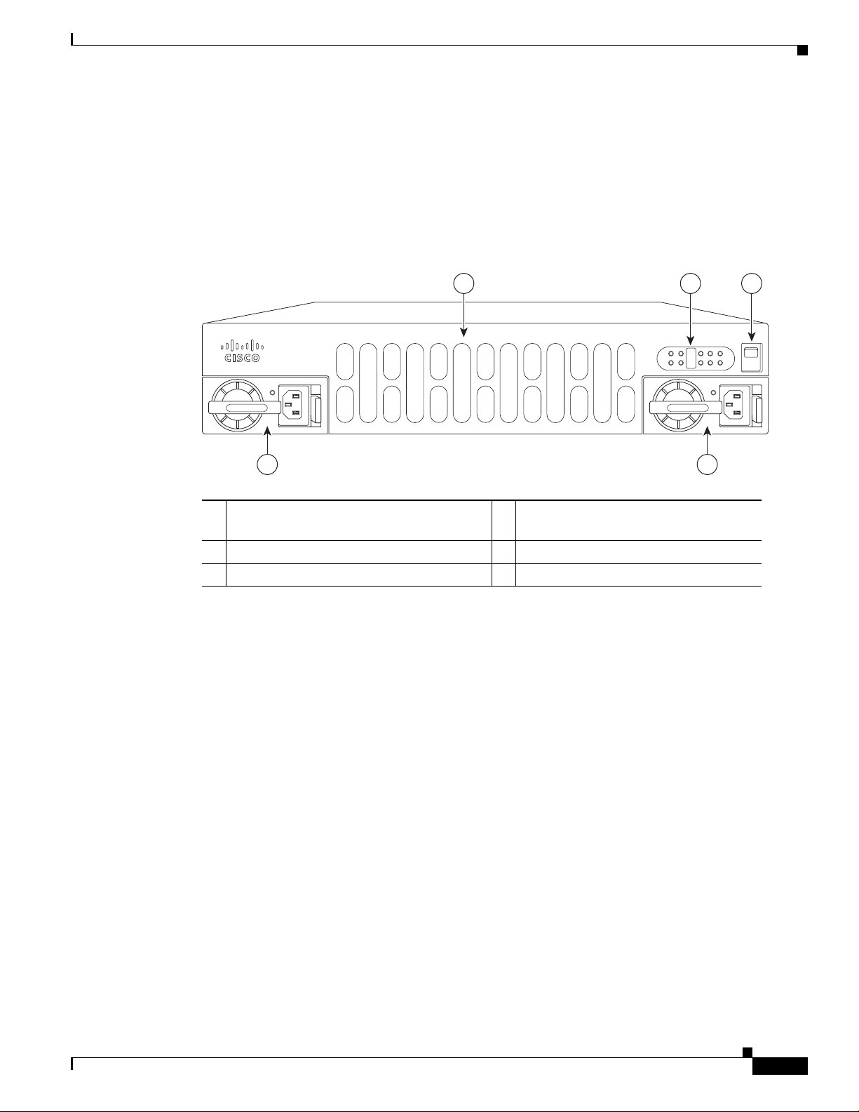
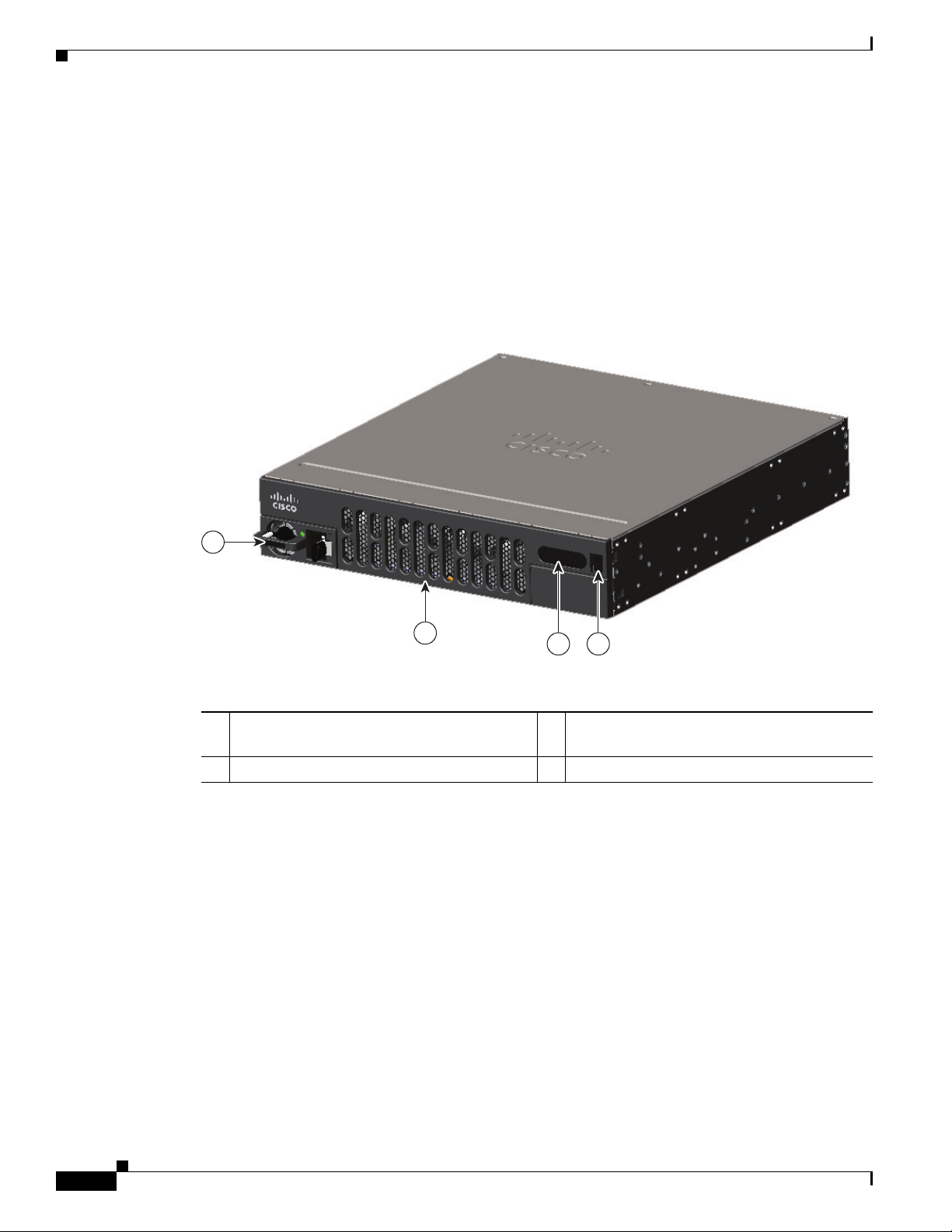
Figure 1-1 Bezel Side of Cisco 4461 ISR with Two PSUs
Chassis Views
OL-32185-02
1 LED 2 Router power On/Off switch
3 Power supply unit (PSU1) 4 Router fan tray (hidden) behind
removable bezel
5 Optional power supply unit (PSU0)
Hardware Installation Guide for the Cisco 4000 Series Integrated Services Router
1-3
Page 12
Chassis Views
Chapter 1 Overview of Cisco 4000 Series ISRs
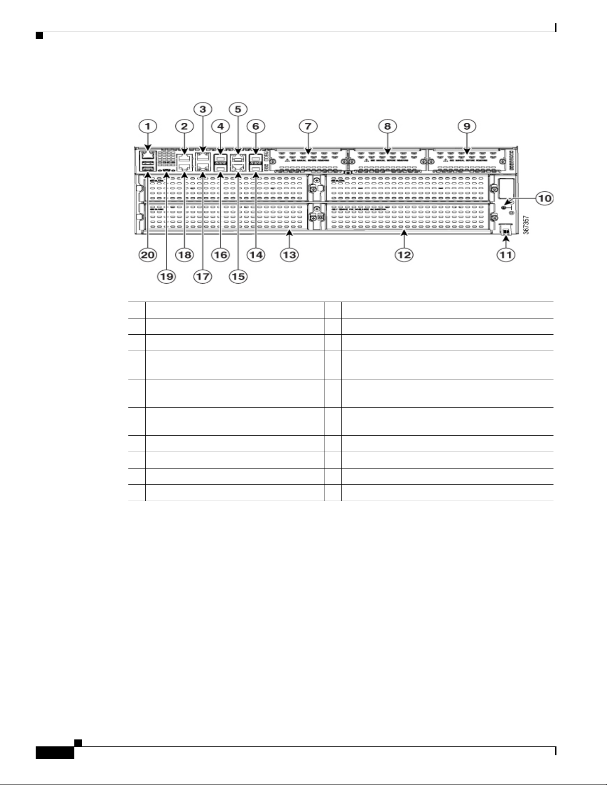
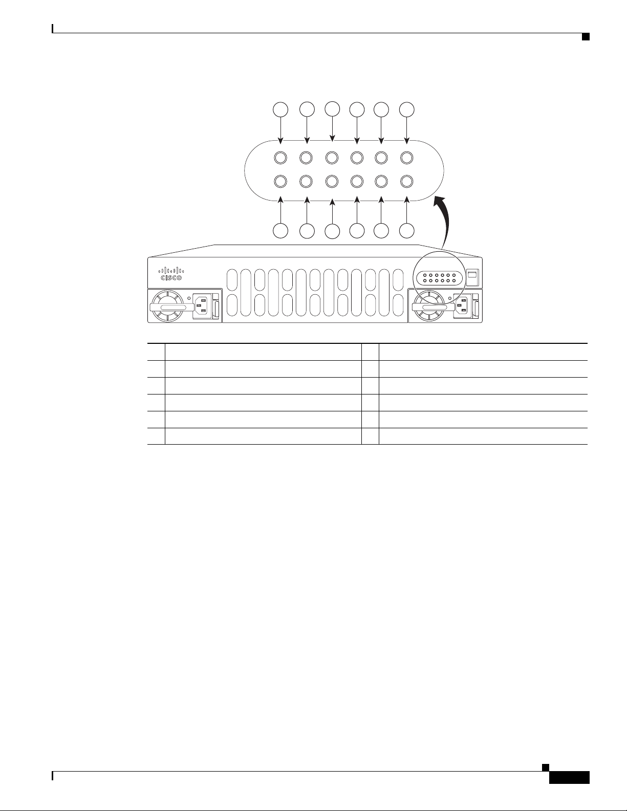
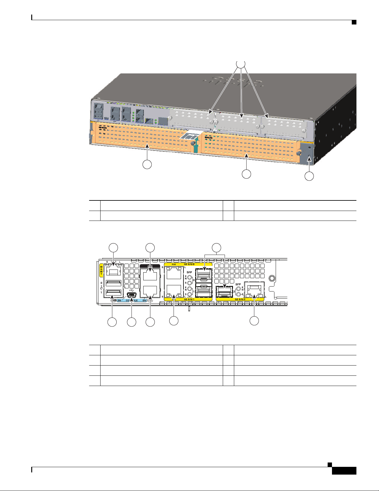
Figure 1-2 Back Panel (I/O Side) Slots and Connectors on Cisco 4461 ISR
1 GE 0 management port 2 Auxiliary port
3 RJ-45 Gigabit Ethernet port (GE 0/0/0) 4 SFP/Gigabit Ethernet port (GE 0/0/0)
5 RJ-45 Gigabit Ethernet port (GE 0/0/2) 6 SFP+/10 Gigabit Ethernet port (
7 NIM slot 1 (shown with slot divider
8 NIM slot 2 (shown with slot divider removed).
removed).
9 NIM slot 3 (shown with slot divider
10 Ground Connection
removed).
11
Slot for label 12 Enhanced Service Module (SM-X) with double
wide
13 Enhanced Service Module (SM-X) 3 14 SFP+/10 Gigabit Ethernet port (
15 RJ-45 Gigabit Ethernet port (GE 0/0/3) 16 SFP/Gigabit Ethernet port (GE 0/0/1)
17 RJ-45 Gigabit Ethernet GE 0/01 18 Console Port
19 USB Console Port 20 USB Port
TE 0/0/4)
TE0/0/5)
1-4
Hardware Installation Guide for the Cisco 4000 Series Integrated Services Router
OL-32185-02
Page 13
Chapter 1 Overview of Cisco 4000 Series ISRs
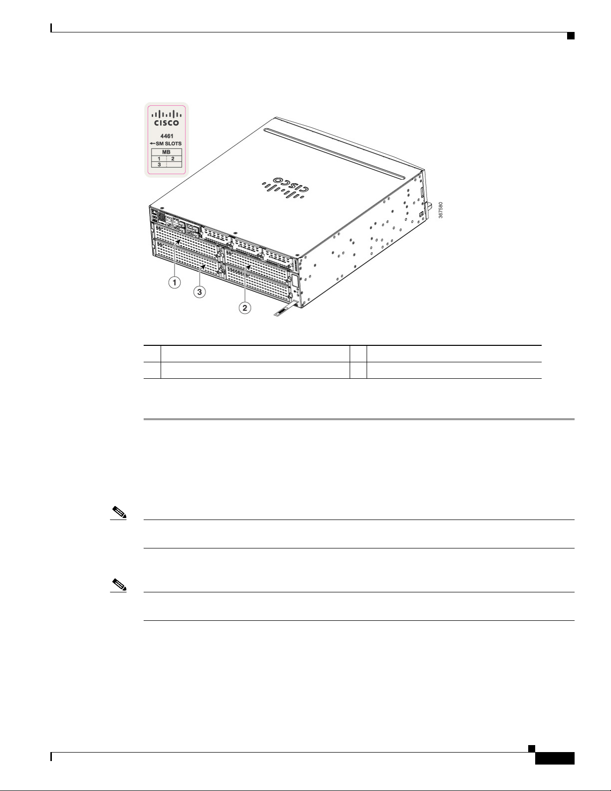
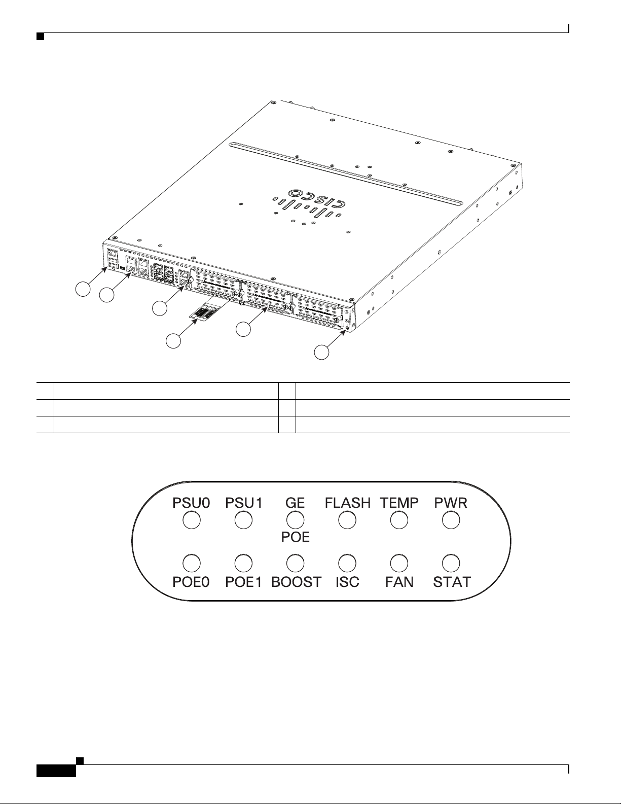
Figure 1-3 NIM and SM-X Slots
Chassis Views
1 SM-X slot 1 2 SM-X slot 2
3 SM-X slot 3
To remove an SM-X:
Step 1 Read the “Safety Warnings” section and disconnect the power supply before you replace any module.
Step 2 Access the SM-X slot. See Figure 1-3 for the various NIM and SM-X slot locations.
Step 3 Loosen the captive screws to open the slot cover.
Step 4 Pull the SM-X out of the connector on the motherboard. Keep the SM-X parallel with the motherboard
to prevent damage to the slot and standoff.
Note When you remove the SM-X slot 2, it removes the blank slot which is attached to the special divider.
See Figure 1-4.
Step 5 Place the SM-X in an anti-static bag to protect it from ESD damage.
Note For more details on installation of SM-Xs, NIMs, and Cisco E-Series Server Modules, see the hardware
installation guide for the particular module you have purchased.
OL-32185-02
Hardware Installation Guide for the Cisco 4000 Series Integrated Services Router
1-5
Page 14

Chassis Views
Chapter 1 Overview of Cisco 4000 Series ISRs
Figure 1-4 NIM and SM-X Slot with Divider
NIM slot 1 and 2 2 SM-X slot divider
1-6
Hardware Installation Guide for the Cisco 4000 Series Integrated Services Router
OL-32185-02
Page 15

Chapter 1 Overview of Cisco 4000 Series ISRs
Figure 1-5 Bezel Side LEDS of the Cisco 4461 ISR Model
Chassis Views
OL-32185-02
1 PSU0: Power supply unit 0 2 PSU1: Power supply unit 1
3 GE POE: Internal PoE daughter card status 4 FLASH: Compact flash status
5 TEMP: Temperature status 6 PWR: Power
7 STAT: System status 8 FAN: Fan status
9 M.2 SSD status 10 POE BOOST: Power over Ethernet boost mode
11 POE 1: Power over Ethernet 1status 12 POE 0: Power over Ethernet 0 status
Hardware Installation Guide for the Cisco 4000 Series Integrated Services Router
1-7
Page 16
Chassis Views
Platform Summary
Chapter 1 Overview of Cisco 4000 Series ISRs
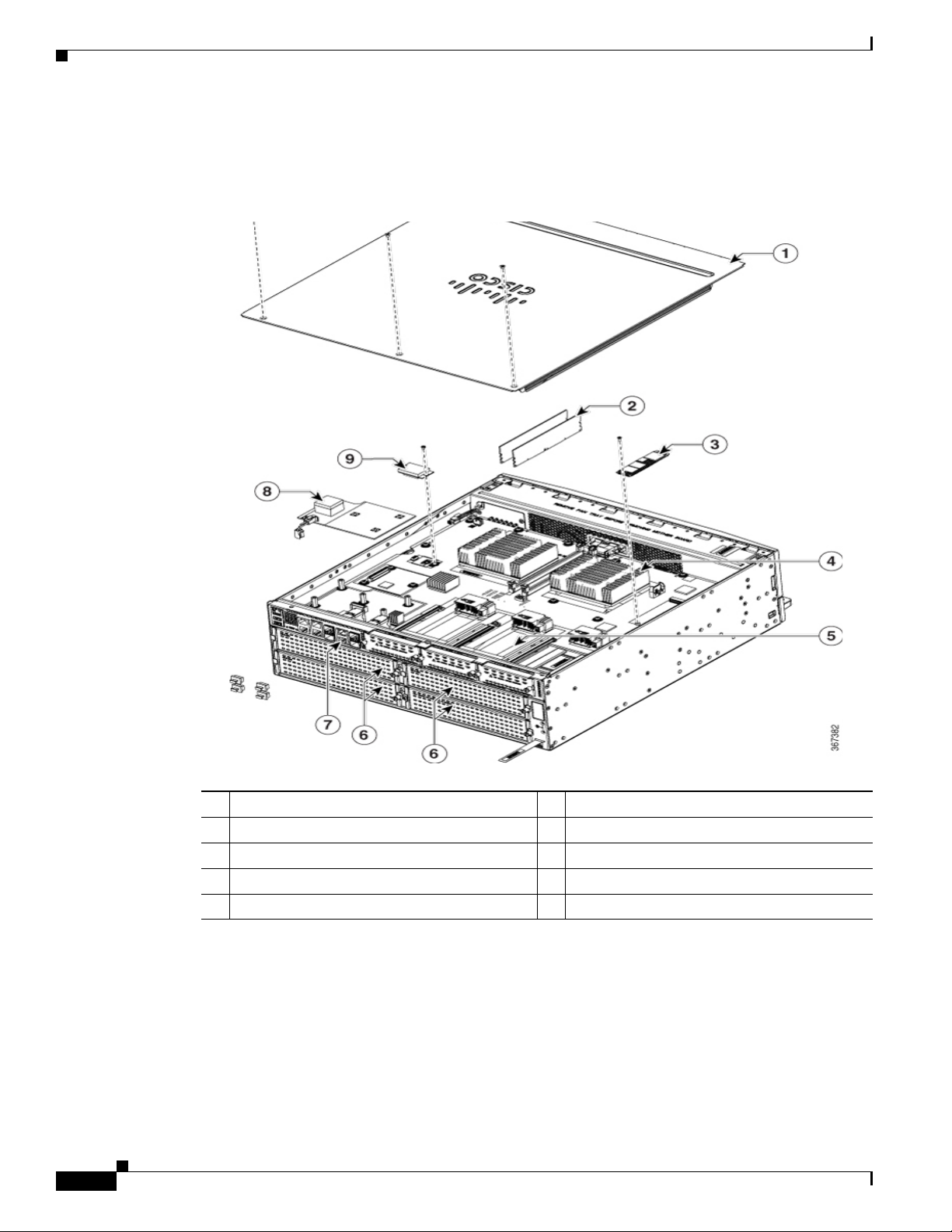
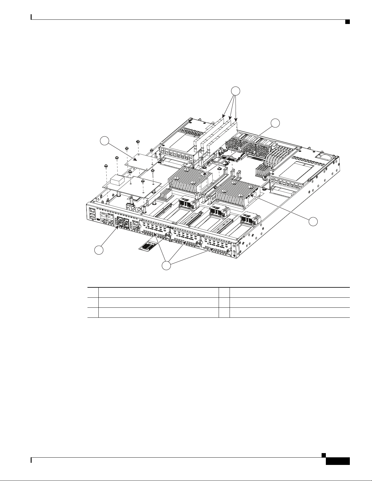
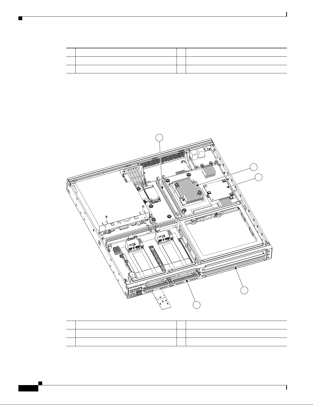
Figure 1-6 shows the internal view of Cisco 4461 with parts and module locations.
Figure 1-6 Platform Summary of Cisco 4461 ISR
1-8
1 Cover 2 DIMMs
3 SSD M.2 storage device 4 CPU
5 NIM Slot 6 SM-X Slot 1, 2, and 3
7 RJ-45 Gigabit Ethernet port (GE 0/0/3) 8 POE daughter card
9 Flash Memory Card
Hardware Installation Guide for the Cisco 4000 Series Integrated Services Router
OL-32185-02
Page 17
Chapter 1 Overview of Cisco 4000 Series ISRs
Cisco 4400 Series
285695
PSU1 PSU2
POE1 POE2
FLASH TEMP PWR
VM FAN STAT
INT
POE
BOOST
1 2 3
54
Cisco 4451-X ISR Chassis
Bezel view of the Cisco 4451-X ISR with two PSUs. Cisco 4451-X ISR routers support these slot types:
- Network Interface Modules (NIMs)
- Service modules (SM-X, like SM-X-1T3/E3)
- E-Series Server Modules.
Figure 1-7 Bezel View
Chassis Views
1 Router fan tray (hidden) behind removable
2 LEDs
bezel
3 Router power On/Off switch 4 AC power supply unit (PSU0)
5 AC power supply unit (PSU1)
Back panel slots and ports of the Cisco 4451-X ISR.
OL-32185-02
Hardware Installation Guide for the Cisco 4000 Series Integrated Services Router
1-9
Page 18

Chassis Views
Chapter 1 Overview of Cisco 4000 Series ISRs
Figure 1-8 Back Panel (I/O Side) Slots and Connectors on Cisco 4451-X ISR
1 2 3 5 6 8 9 10 11
4 7
2
1
1923 16
21 2022
18 17 15
14
13 12
1 GE 0 management port 2 Auxiliary port
3 RJ-45 Gigabit Ethernet port (GE 0/0/0) 4 LEDs for the GE 0/0/0 interface (See Table 1-1
for detailed LED information)
5 SFP/Gigabit Ethernet port (GE 0/0/0) 6 SFP/Gigabit Ethernet port (GE 0/0/2)
7 LEDs for the GE 0/0/2 interface 8 RJ-45 Gigabit Ethernet port (GE 0/0/2)
9 NIM slot 1 (shown with slot divider
10 NIM slot 2 (shown with slot divider removed).
removed).
11 NIM slot 3 12 Ground connection
13 Enhanced Service Module (SM-X) 2 14 Enhanced Service Module (SM-X) 1
15 RJ-45 Gigabit Ethernet port GE 0/0/3 16 LEDs for the GE 0/0/3 interface
17 SFP/Gigabit Ethernet GE 0/0/3 18 SFP Gigabit Ethernet GE 0/0/1
19 LEDs for the GE 0/0/1 interface 20 RJ-45 Gigabit Ethernet port GE 0/0/1
21 Serial console port 22 USB Type B mini port
23 USB 0 and USB 1
285698
1-10
Hardware Installation Guide for the Cisco 4000 Series Integrated Services Router
OL-32185-02
Page 19
Chapter 1 Overview of Cisco 4000 Series ISRs
Figure 1-9 Bezel Side LEDS of the Cisco 4451-X ISR Model
Chassis Views
3
2
1
4 5 6
PSU0 PSU1 FLASH TEMP PWR
GE
POE
POE0
12
POE1
11
BOOST
10
ISC
9 8
FAN
STAT
7
Cisco 4400 Series
PSU1 PSU2
FLASH TEMP PWR
INT
PSU0 PSU1 FLASH TEMP PWR
GE
POE
POE
BOOST
POE1 POE2
BOOST
FAN
VM FAN STAT
ISC
POE0
POE1
STAT
285696
1 PSU0: Power supply unit 1 2 PSU1: Power supply unit 2
3 GE POE: Internal PoE daughter card status 4 FLASH: Compact flash status
5 TEMP: Temperature status 6 PWR: Power
7 STAT: System status 8 FAN: Fan status
9 ISC: Integrated Services Card status 10 POE BOOST: Power over Ethernet boost mode
11 POE 1: Power over Ethernet 1status 12 POE 0: Power over Ethernet 0 status
OL-32185-02
Hardware Installation Guide for the Cisco 4000 Series Integrated Services Router
1-11
Page 20

Chassis Views
1
8
2
3
4
5
6
7
391821
Platform Summary
Chapter 1 Overview of Cisco 4000 Series ISRs
Figure 1-6 shows the internal view of Cisco 4451-X ISR with parts and module locations.
Figure 1-10 Platform Summary of Cisco 4451-X ISR
1 Forwarding plane processor 2 Control plane processor
3 Control plane processor DIMMs 4 NIM 3 (single-wide) slot
5 Enhanced Service Module (SM-X) slots 6 NIM slot 1 and 2 (shown with slot divider
removed)
7 SFP GE ports 8 Forwarding plane processor DIMM
Cisco 4431 ISR Chassis
Cisco 4431 ISR supports the Network Interface Modules (NIMs) and Integrated Services Card (ISC slots
for PVDM4s).
Hardware Installation Guide for the Cisco 4000 Series Integrated Services Router
1-12
OL-32185-02
Page 21

Chapter 1 Overview of Cisco 4000 Series ISRs
1
2
3
4
391891
Figure 1-11 Bezel View of Cisco 4431 ISR with Two Power Supply Units
1 Power supply unit (PSU1) 2 LEDs
3 On/Off switch 4 Optional power supply unit (PSU0)
Chassis Views
OL-32185-02
Hardware Installation Guide for the Cisco 4000 Series Integrated Services Router
1-13
Page 22
Chassis Views
390641
1
2
3
4
5
6
Figure 1-12 View of Cisco 4431 ISR Chassis
Chapter 1 Overview of Cisco 4000 Series ISRs
1 USB ports 2 GE ports
3 Screws to open the NIM slot 4 Router label tray
5 NIM slot (with cover) 6 Ground connection
Figure 1-13 LEDs on the Cisco 4431 ISR
For detailed information on LEDs, see the “LED Indicators” section on page 1-29.
390639
Hardware Installation Guide for the Cisco 4000 Series Integrated Services Router
1-14
OL-32185-02
Page 23
Chapter 1 Overview of Cisco 4000 Series ISRs
391943
4
5
3
6
2
1
Platform Summary
Figure 1-14 shows the internal view of Cisco 4431 ISR with parts and module locations.
Figure 1-14 Platform Summary of the Cisco 4431 ISR
Chassis Views
1 DIMMs 2 Forwarding plane processor
3 Control plane processor 4 NIMs
5 SFP GE ports 6 PVDM card
Hardware Installation Guide for the Cisco 4000 Series Integrated Services Router
OL-32185-02
1-15
Page 24
Chassis Views
Cisco 4351 ISR Chassis
This section contains the following views of Cisco 4351ISR chassis:
• Power Supply and Bezel Side View of Cisco 4351 ISR (Figure 1-15)
• Back Panel Ports, Slots, and Serial Number on Cisco 4351 ISR (Figure 1-16)
• Ports on Cisco 4351 ISR (Figure 1-17)
• LEDs on Cisco 4351 ISR (Figure 1-18)
Figure 1-15 Power Supply and Bezel Side View of Cisco 4351 ISR
Chapter 1 Overview of Cisco 4000 Series ISRs
1
2
3 4
1 Power supply unit 2 Router fan tray (hidden behind the removable
bezel)
3 LEDs 4 Router power On/Off switch
391464
1-16
Hardware Installation Guide for the Cisco 4000 Series Integrated Services Router
OL-32185-02
Page 25
Chapter 1 Overview of Cisco 4000 Series ISRs
1
2
3
4
Figure 1-16 Back Panel Ports, Slots, and Serial Number on Cisco 4351 ISR
Chassis Views
1 Enhanced Service Module (SM-X) slot 2 Enhanced Service Module (SM-X) slot
3 Ground connection 4 NIM slots
Figure 1-17 Ports on Cisco 4351 ISR
1
2
4
3
5
6
7
391467
8
1 GE management port 2 USB Type A port
3 USB Type B mini port 4 Auxiliary port
5 Console port 6 RJ-45 port (GE 0/0/1)
7 SFP port (GE 0/0/0) 8 RJ-45 port (GE/0/0/2)
OL-32185-02
Hardware Installation Guide for the Cisco 4000 Series Integrated Services Router
1-17
Page 26

Chassis Views
391466
391829
7
5
8
6
9
10
1
2
3
4
Platform Summary
Chapter 1 Overview of Cisco 4000 Series ISRs
Figure 1-18 LEDs on Cisco 4351 ISR
For detailed information on LEDs, see the “LED Indicators” section on page 1-29.
Figure 1-19 shows the internal view of Cisco 4351 ISR chassis with parts and module locations.
Figure 1-19 Platform Summary of Cisco 4351 ISR Chassis
1 CPU 2 DIMMs
3 Flash memory card connector 4 SSD mSATA connector
5 NIM slot 3 6 NIM slot 2
7 SM-X slots 8 NIM slot 1
9 RJ-45 GE ports 10 ISC slot
Hardware Installation Guide for the Cisco 4000 Series Integrated Services Router
1-18
OL-32185-02
Page 27

Chapter 1 Overview of Cisco 4000 Series ISRs
1
2
3
4
5
391463
Cisco 4331 ISR Chassis
This section contains the following views of Cisco 4331 ISR router:
• Bezel Side Ports and LEDs on Cisco 4331 ISR (Figure 1-20)
• Back Panel Ports and Slots on Cisco 4331 ISR (Figure 1-21)
Figure 1-20 Bezel Side Ports and LEDs on Cisco 4331 ISR
3 5
Chassis Views
391462
1 2
4 6 7
1 USB Type B mini port 2 Serial console port
3 AUX port 4 USB Type A port
5 Management port 6 LEDs
7 AC Power
Figure 1-21 Back Panel Ports and Slots on Cisco 4331 ISR
Hardware Installation Guide for the Cisco 4000 Series Integrated Services Router
OL-32185-02
1-19
Page 28
Chassis Views
1
2
3
4
5
391946
Platform Summary
Chapter 1 Overview of Cisco 4000 Series ISRs
1 Double-wide NIM 2 NIMs
3 Removable module slot divider 4 SM-X slot
5 Ground connection
For detailed information on LEDs, see the “LED Indicators” section on page 1-29.
Figure 1-22 shows the internal view of the Cisco 4431 ISR with parts and module locations.
Figure 1-22 Platform Summary of Cisco 4331 ISR Chassis
1 DIMMs 2 CPU
3 ISC slot 4 SM-X slot
5 NIM slot
1-20
Hardware Installation Guide for the Cisco 4000 Series Integrated Services Router
OL-32185-02
Page 29

Chapter 1 Overview of Cisco 4000 Series ISRs
391468
3 4 7 9
1 2
5
10
86
391469
1
Cisco 4321 ISR Chassis
This section contains the following views of Cisco 4321 ISR router:
• Back Panel Ports on Cisco 4321 ISR
• LEDs on Cisco 4321 ISR (Figure 1-23)
• LEDs on Cisco 4321 ISR (Figure 1-24)
Figure 1-23 Back Panel Ports on Cisco 4321 ISR
Chassis Views
1 Grounding 2 Power switch
3 Power input connector 4 GE “MGMT” port (with USB port below)
5 USB Type B mini port 6 Console port
7 Auxiliary port 8 GE 0/0/1 (copper cable) port
9 GE 0/0/0 RJ-45 (copper cable) port 10 GE 0/0/0 SFP (fiber-optic) port
Figure 1-24 Back Panel (I/O Side) View of Cisco 4321 ISR
1 NIM slots
OL-32185-02
Hardware Installation Guide for the Cisco 4000 Series Integrated Services Router
1-21
Page 30

Chassis Views
391471
1
Chapter 1 Overview of Cisco 4000 Series ISRs
Figure 1-25 LEDs on Cisco 4321 ISR
Platform Summary
1 LEDs
For detailed information on LEDs, see the “LED Indicators” section on page 1-29.
1-22
Hardware Installation Guide for the Cisco 4000 Series Integrated Services Router
OL-32185-02
Page 31

Chapter 1 Overview of Cisco 4000 Series ISRs
1
2
3
4
5
391947
Figure 1-26 shows the internal view of Cisco 4321 ISR with parts and module locations.
Figure 1-26 Platform Summary of Cisco 4321 ISR Chassis
Chassis Views
1 DIMM 2 CPU
3 ISC slot 4 NIM slots
5 GE ports
Cisco 4221 ISR Chassis
This section contains the following views of Cisco 4221 ISR router:
• Back Panel Ports on Cisco 4221 ISR (Figure 1-27)
• Back Panel (I/O Side) View of Cisco 4221 ISR (Figure 1-28)
• LEDs on Cisco 4221 ISR (Figure 1-29)
OL-32185-02
Hardware Installation Guide for the Cisco 4000 Series Integrated Services Router
1-23
Page 32

Chassis Views
1
365770
Chapter 1 Overview of Cisco 4000 Series ISRs
Figure 1-27 Back Panel Ports on Cisco 4221 ISR
8
1 3 2 5 764
1 Grounding 2 Power input connector
3 Power switch 4 USB
5 Console port 6 GE 0/0/0 RJ-45 (copper cable) port
7 GE 0/0/0 SFP (fiber-optic) port 8 GE 0/0/1 (copper cable) port
Figure 1-28 Back Panel (I/O Side) View of Cisco 4221 ISR
365769
1 NIM slots
1-24
Hardware Installation Guide for the Cisco 4000 Series Integrated Services Router
OL-32185-02
Page 33

Chapter 1 Overview of Cisco 4000 Series ISRs
1
365771
Figure 1-29 LEDs on Cisco 4221 ISR
1 LEDs
For detailed information on LEDs, see the “LED Indicators” section on page 1-29.
Chassis Views
Platform Summary
Figure 1-30 shows the internal view of Cisco 4221 ISR with parts and module locations.
Figure 1-30 Platform Summary of Cisco 4221 ISR Chassis
1
2
3
OL-32185-02
4
5
Hardware Installation Guide for the Cisco 4000 Series Integrated Services Router
365772
1-25
Page 34

Locate Product Identification Details
1 Fan 2 CPU
3 Battery 4 GE 0/0/0/0 RJ-45 (copper cable) port
5 NIM slots
Locate Product Identification Details
Software License
The serial number (SN), product ID (PID), version ID (VID), and Common Language Equipment
Identifier (CLEI) are printed on a label on the back of the router or on a label tray located on the router
chassis or motherboard.
To obtain a software license, you need a product authorization key (PAK) and the unique device
identifier (UDI) of the device where the license is to be installed.
The UDI has two main components:
• Product ID (PID)
• Serial number (SN)
Chapter 1 Overview of Cisco 4000 Series ISRs
The UDI can be viewed using the show license udi command in privileged Exec mode in Cisco Internet
Operating System (IOS) software.
For additional information on the UDI or how to obtain a PAK, see the Cisco Software Activation on
Integrated Services Routers and Cisco Integrated Service Routers Generation 2 document at cisco.com.
Labels on Cisco 4000 Series ISRs
Figure 1-31 shows the location of the labels on Cisco 4451-X ISR. Label are located at the same location
on all routers in the Cisco 4000 series. Though your router may be different from the one shown in
Figure 1-31.
1-26
Hardware Installation Guide for the Cisco 4000 Series Integrated Services Router
OL-32185-02
Page 35

Chapter 1 Overview of Cisco 4000 Series ISRs
302982
2
1
4
3
Figure 1-31 Label Location on Cisco 4451-X ISR
1 Product ID 2 Serial Number
3 PID/VID 4 CLEI
Hardware Features of Cisco 4000 Series ISRs
Additional Help for Locating Cisco 4000 Series ISRs Labels
Use the Cisco Product Identification (CPI) tool to find labels on the router. The tool provides detailed
illustrations and descriptions of where labels are located on Cisco products. It includes the following
features:
• A search option that allows browsing for models by using a tree-structured product hierarchy
• A search field on the final results page that makes it easier to look up multiple products
• End-of-sale products clearly identified in results lists
The tool streamlines the process of locating serial number labels and identifying products. Serial number
information expedites the entitlement process and is required for access to support services.
Hardware Features of Cisco 4000 Series ISRs
This section describes the hardware features of Cisco 4000 Series ISRs.
• Built-In Interface Ports, page 1-27
• LED Indicators, page 1-29
• Fans, Ventilation, and Airflow, page 1-38
Built-In Interface Ports
OL-32185-02
Cisco 4000 Series ISRs have multiple 10/100/1000 front panel ports, SFPs, and 10/100/1000
management ports.
Hardware Installation Guide for the Cisco 4000 Series Integrated Services Router
1-27
Page 36

Hardware Features of Cisco 4000 Series ISRs
Dual Mode GE or SFP Ports
There are dual mode ports available on the router which can function as GE or SFP ports.
GE Ports
The GE RJ-45 copper interface ports support 10BASE-T, 100BASE-TX, and 1000BASE-T.
SFP Ports
The small-form-factor pluggable (SFP) ports support, 1000BASE-LX/LH, 1000BASE-SX,
1000BASE-ZX, and Coarse Wavelength-Division Multiplexing (CWDM-8) modules, as well as 100Mbs
SFP modules.
The SFP port shares the same physical port as an RJ-45 GE port with the same number. At a time, it can
be used for only one function. As described in the IEEE 802.3ah specification, the SFP port supports
auto-media-detection, auto-failover, and remote fault indication (RFI).
Use the media-type command to enable the auto-media-detection and auto-failover features.
You can configure the SFP port by using the media-type configuration command to select either the
RJ-45 or the SFP connector. When the media-type is not configured, by default, the auto-select feature
is enabled. The auto-select feature automatically detects the media that is connected and links it up. If
both media are connected, the media that comes up first is linked, and it is treated as the primary media.
This primary media is explicitly indicated as an SFP or RJ-45 link. When the router receives an
indication that the primary media is down, the secondary failover media is enabled. After the switchover,
when the primary media is later restored, the media does not switch back to the primary media. By
default, the RJ-45 port is configured as the primary media-type and if it fails, the media failovers to the
SFP port. Conversely, when the SFP port is configured as the primary media-type and if it fails, the
media switches to the RJ-45 port.
Chapter 1 Overview of Cisco 4000 Series ISRs
USB Serial Console Port
The Mini-USB type B serial port can be used as an alternative to the RJ-45 console port. For Windows
operating systems earlier than Windows 7, you must install a Windows USB device driver before using
the USB console port.
Note Cisco 4461 supports Mini-USB type B serial port and Micro-USB type B serial port.
Front Panel PoE+ Ports
On Cisco 4451-X ISR and Cisco 4351 ISR, two front panel Ethernet ports are PoE+ (802.3at) compliant
ports. These are ports GE 0/0/0 and GE 0/0/1. Cisco 4431 ISR, Cisco 4321 ISR and Cisco 4221 do not
support front panel PoE+.
System PoE power supplies do not provide power to the front panel ports.
Internal PoE Daughter Card
The internal PoE daughter card provides a total of 30.8 watts of power across the two ports.
1-28
Hardware Installation Guide for the Cisco 4000 Series Integrated Services Router
OL-32185-02
Page 37

Chapter 1 Overview of Cisco 4000 Series ISRs
Hardware Features of Cisco 4000 Series ISRs
LED Indicators
Table 1-1 summarizes the LED indicators that are located in the router bezel or chassis, but not on the
interface cards and modules.
Note For module LEDs, please refer to the respective module installation guides for each module.
1
Table 1-1 LED Descriptions (Applies to Cisco 4461 ISR, Cisco 4451-X ISR, Cisco 4431 ISR, and Cisco 4351 ISR)
LED Represents Color Description Location Available On
STAT System
Status
TEMP Temperature
Status
FAN Fan Status Green All fans are operating. Bezel side All models
L
(left)
S
(left)
Ethernet
ports 0 and 1
Link
Speed of
Ethernet
ports 0 and 1
Solid
System operates normally. Bezel side All models
green
Blinking
BIOS/Rommon is booting.
amber
Amber BIOS/Rommon has completed booting, and system
is at Rommon prompt or booting platform software.
Off System is not out of reset or BIOS image is not
loadable.
Solid
green
All temperature sensors in the system are within
acceptable range.
Amber One or more temperature sensors in the system are
outside the acceptable range.
Off Temperature is not being monitored.
Amber One fan has stopped working.
Blinking
Amber
Two or more fans have stopped working, or the fan
tray has been removed.
Off Fans are not being monitored.
Green Ethernet cable is present and link is established with
other side or PoE power is enabled for this port.
Off No link.
Green
Blinking
Blink frequency indicates port speed:
• 1 blink+ pause - FE or GE port operating at 10
Mb/s
• 2 blinks + pause - FE or GE port operating
at100 Mb/s
• 3 blinks + pause - GE port operating at1000
Mb/s
Off No link or a non-Ethernet 802.3af/t capable device
is plugged in and powered over the PoE.
Bezel side All models
I/O side All models
I/O side All models
OL-32185-02
Hardware Installation Guide for the Cisco 4000 Series Integrated Services Router
1-29
Page 38

Chapter 1 Overview of Cisco 4000 Series ISRs
Hardware Features of Cisco 4000 Series ISRs
Table 1-1 LED Descriptions (Applies to Cisco 4461 ISR, Cisco 4451-X ISR, Cisco 4431 ISR, and Cisco 4351 ISR)
LED Represents Color Description Location Available On
L
(right)
Ethernet
ports 2 and 3
and
Management
Ethernet
Link
S
(right)
Ethernet
ports 2, and
1
3
and
Management
Ethernet
Speed
SFP EN Port 0, 1, 2,
and 3 Enable
SFP S Status of
Ports 0, 1, 2,
and 3
L/A SFP+port 0/1
Link Active
SER
CON
(right)
USB
CON
Serial
Console
Active
USB Console
Active
(left)
SSD mSATA/M.2
Slot Status
ISC ISC Slot
Status
Green Ethernet cable is present and link is established with
1
other side.
Off No link.
Green Blink frequency indicates port speed:
• 1 blink+ pause - FE or GE port operating at 10
Mb/s
• 2 blinks + pause - FE or GE port operating
at100 Mb/s
• 3 blinks + pause - GE port operating at1000
Mb/s
Off No link
Green Present and enabled. I/O side All models
Amber Present with failure.
Off Not present.
Blinking
Green
Blinking frequency indicates port speed. See the
definition for the S LED.
Amber Initialized with error.
Off Not present.
Green Link established. I/O side Cisco 4461 ISR
Blinking
Packets being transmitted.
Green
Off Not present.
Green Active console port is RJ-45.
Note When this LED is on, the USB CON LED
will be off.
Green Active console port is USB.
Note When this LED is on, the SER CON LED
will be off.
Green SSD mSATA/M.2 present and enabled. Bezel side Cisco 4351ISR and
Amber Initialized with error.
Off Not present.
Green PVDM4 is present and is enabled. Bezel side All models
Amber Initialized with error.
Off Not present.
I/O side All models
I/O side All models
I/O side All models
I/O side All models
I/O side All models
Cisco 4461 ISR
1
1
2
1-30
Hardware Installation Guide for the Cisco 4000 Series Integrated Services Router
OL-32185-02
Page 39

Chapter 1 Overview of Cisco 4000 Series ISRs
Hardware Features of Cisco 4000 Series ISRs
Table 1-1 LED Descriptions (Applies to Cisco 4461 ISR, Cisco 4451-X ISR, Cisco 4431 ISR, and Cisco 4351 ISR)
LED Represents Color Description Location Available On
FLASH System Flash
Status
PSU Power
Supply Unit
(P0 and P1)
Status
POE PSU
(not
supported
in Cisco
IOS XE
Power Over
Ethernet
Power
Supply Unit
0and 1 Status
3.8)
POE
Boost
(not
Power Over
Ethernet
Boost Mode
supported
in Cisco
IOS XE
3.8)
GE POE Internal PoE
Daughter
Card Status
Blinking
Green
Compact flash/eUSB flash is present and is
currently being accessed.
Note Do not remove the flash device while the
system is powered on.
Green PSU is on and provides power. Bezel side All models
Amber PSU is on but with errors or in a failure condition.
Off Power supply is turned off.
Green PSU is on and provides power. Bezel side All models1
Amber PSU is on but with errors or in a failure condition.
Off PSU is off.
Green Two PoE power supplies are installed and operating
in boost mode.
Off This can mean one of the following:
• No PoE PSU is installed.
• One PoE PSU is installed.
• Two PoE PSUs are installed and operate in
redundant mode.
Green PSU is installed and provides power Bezel side All models
Amber PSU is installed but in a failure condition.
Off PSU is off.
Bezel side All models
3
Bezel side Cisco 4451-X ISR,
Cisco ISR4431
3
PWR System
Power
Green System power is on and system functions correctly. Bezel side All models
Green
System power is in the process of shutting down.
blinking
Amber System power is up, but low level initialization has
failed.
Amber
blinking:
System power is up, but the system has failed to
come out of reset.
Off System power is off.
AC OK AC power
status
1. Cisco 4351ISR does not have SPF 3.
2. Cisco 4461 ISR does not have ISC.
3. Cisco 4351 ISR does not support POE PSU 1.
OL-32185-02
Green AC power is on. On each
Off AC power is off.
All models
power
supply unit
Hardware Installation Guide for the Cisco 4000 Series Integrated Services Router
1-31
Page 40

Chapter 1 Overview of Cisco 4000 Series ISRs
Hardware Features of Cisco 4000 Series ISRs
Table 1-2 LED Descriptions (Applies to the Cisco 4331 ISR and the Cisco 4321 ISR Routers)
Available
LED Represents Color Description Location
STAT System Status Solid green System operates normally. Bezel side All models
Blinking
BIOS/Rommon is booting.
amber
Amber BIOS/Rommon has completed booting, and system
is at Rommon prompt or booting platform software.
Off System is not out of reset or BIOS image is not
loadable.
TEMP Temperature
Status
Solid green All temperature sensors in the system are within
acceptable range.
Bezel side All models
Amber One or more temperature sensors in the system are
outside the acceptable range.
Off Temperature is not being monitored.
FAN Fan Status Green All fans are operating. Bezel side All models
Amber One fan has stopped working.
Blinking
Amber
Two or more fans have stopped working, or the fan
tray is removed.
Off Fans are not being monitored.
L Ethernet ports 0
and 1
1
Green Ethernet cable is present and link is established with
other side.
I/O side All models
Off No link.
S Speed of Ethernet
ports 0 and 1
Green
Blinking
Blink frequency indicates port speed:
• 1 blink - 10-Mbps link speed
• 2 blinks - 100-Mbps link speed
I/O side All models
On
SFP EN Port 0, and 1 (for
Cisco 4331 ISR),
and Port 0 for
Cisco 4321 ISR)
Enable
SFP S Status of port 0,
and 1 (for
Cisco 4331 ISR),
and Port 0 for
Cisco 4321 ISR)
SER CON
(right)
Serial Console
Active
Hardware Installation Guide for the Cisco 4000 Series Integrated Services Router
1-32
• 3 blinks - 1000-Mbps link speed
Off No link or a non-Ethernet 802.3af/t capable device is
plugged in and powered over the PoE.
Green SFP module is detected and recognized. I/O side All models
Amber Initialized with error.
Off Not present.
Green SFP module is detected and recognized. I/O side All models
Amber Initialized with error.
Off Not present.
Off Not present.
Green Active console port is RJ-45.
Note When this LED is on, the USB CON LED
I/O side
2
All models
will be off.
OL-32185-02
Page 41

Chapter 1 Overview of Cisco 4000 Series ISRs
Hardware Features of Cisco 4000 Series ISRs
Available
LED Represents Color Description Location
USB CON
(left)
USB Console
Active
Green Active console port is USB.
Note When this LED is on, the SER CON LED
I/O side
will be off.
SSD
mSATA Slot Status Green SSD mSATA is present and enabled. Bezel side All
Amber Initialized with error.
Off Not present.
POE0
POE PSU Green PoE is on and provides power. Bezel side All
Amber PoE is in a failed condition.
Off PoE supply is not present.
ISC ISC Slot Status Green PVDM4 is present and enabled. Bezel side All models
Amber Initialized with error.
Off Not present.
FLASH System Flash
Status
Blinking
Green
Compact flash/eUSB flash is present and currently
being accessed.
Note Do not remove the flash device while the
Bezel side All models
system is powered on.
PWR System Power Green System power is on and system functions correctly. Bezel side All models
Green
System power is in the process of shutting down.
blinking
Amber System power is up, but low level initialization has
failed.
Amber
blinking:
System power is up, but the system has failed to
come out of reset.
Off System power is off.
1. Management Ethernet Link on bezel side on Cisco 4331 ISR.
2. These LEDs are on the bezel side for Cisco 4331 ISR
On
2
All models
models.
models.
Table 1-3 LED Descriptions (Applies to the Cisco 4221 ISR Router)
Available
LED Represents Color Description Location
On
STAT System Status Solid green System operates normally. Bezel side All models
Blinking
BIOS/Rommon is booting.
amber
Amber BIOS/Rommon has completed booting, and system
is at Rommon prompt or booting platform software.
Off System is not out of reset or BIOS image is not
loadable.
Hardware Installation Guide for the Cisco 4000 Series Integrated Services Router
OL-32185-02
1-33
Page 42

Chapter 1 Overview of Cisco 4000 Series ISRs
Hardware Features of Cisco 4000 Series ISRs
Available
LED Represents Color Description Location
TEMP Temperature
Status
Solid green All temperature sensors in the system are within
acceptable range.
Bezel side All models
Amber One or more temperature sensors in the system are
outside the acceptable range.
Off Temperature is not being monitored.
FAN Fan Status Green All fans are operating. Bezel side All models
Amber One fan has stopped working.
Blinking
Amber
Two or more fans have stopped working, or the fan
tray is removed.
Off Fans are not being monitored.
L Ethernet ports 0
and 1
1
Green Ethernet cable is present and link is established with
other side.
I/O side All models
Off No link.
S Speed of Ethernet
ports 0 and 1
Green
Blinking
Blink frequency indicates port speed:
• 1 blink - 10-Mbps link speed
• 2 blinks - 100-Mbps link speed
I/O side All models
On
• 3 blinks - 1000-Mbps link speed
Off No link or a non-Ethernet 802.3af/t capable device is
plugged in and powered over the PoE.
SER CON
(right)
Serial Console
Active
Green Active console port is RJ-45.
Note When this LED is on, the USB CON LED is
I/O side
2
All models
off.
2
USB CON
(left)
USB Console
Active
Green Active console port is USB.
Note When this LED is on, the SER CON LED is
I/O side
All models
off.
Off PoE supply is not present.
ISC ISC Slot Status Green PVDM4 is present and enabled. Bezel side All models
Amber Initialized with error.
Off Not present.
FLASH System Flash
Status
Blinking
Green
Compact flash/eUSB flash is present and currently
being accessed.
Note Do not remove the flash device while the
Bezel side All models
system is powered on.
1-34
Hardware Installation Guide for the Cisco 4000 Series Integrated Services Router
OL-32185-02
Page 43

Chapter 1 Overview of Cisco 4000 Series ISRs
Hardware Features of Cisco 4000 Series ISRs
Available
LED Represents Color Description Location
On
PWR System Power Green System power is on and system functions correctly. Bezel side All models
Green
System power is in the process of shutting down.
blinking
Amber System power is up, but low level initialization bas
failed.
Amber
blinking:
System power is up, but the system has failed to
come out of reset.
Off System power is off.
1. Management Ethernet Link on bezel side on Cisco 4221 ISR.
2. These LEDs are on the bezel side for Cisco 4221 ISR
Removable and Interchangeable Modules and Cards
Service Modules (SM-Xs), Network Interface Modules (NIMs), and E-Series Server Modules, fit into
external slots and can be removed or replaced without opening the chassis.
External Slots
• Network Interface Modules and Service Modules, page 1-35
• Cisco UCS E-Series Server Modules, page 1-36
• Memory, page 1-37
Internal Slots
• Memory, page 1-37
• Memory, page 1-37
• System Flash, page 1-36
See the Overview of Cisco Network Modules and Service Modules for Cisco Access Routers
document for general information and single- and double-wide slot numbering.
See the “Install and Remove NIMs and SM-Xs on Cisco 4000 Series ISRs” section on page 5-30 for
instructions that describe how to install SM-Xs and NIMs in the router.
See the Overview of Cisco Interface Cards for Cisco Access Routers for general interface card
information.
See the Installing Cisco Interface Cards in Cisco Access Routers document, for instructions that
describe how to install legacy interface cards in the router.
Note See the router product page at cisco.com for a list of supported network modules and interface cards.
Network Interface Modules and Service Modules
To install NIMs and SM-Xs on the router chassis, see the “Install and Remove NIMs and SM-Xs on
Cisco 4000 Series ISRs” section on page 5-30.
Hardware Installation Guide for the Cisco 4000 Series Integrated Services Router
OL-32185-02
1-35
Page 44

Hardware Features of Cisco 4000 Series ISRs
Cisco UCS E-Series Server Modules
Cisco UCS E-Series Servers (E-Series Servers) are the next generation of Cisco UCS Express servers.
E-Series Servers are a family of size-, weight-, and power-efficient blade servers that are housed within
the Generation 2 Cisco Integrated Services Routers (ISR G2) and Cisco 4000 Series Integrated Services
Router. For more information on the E-Series Server Modules, see the Cisco UCS E-Series Servers
Configuration Guides.
System Flash
Depending on the model that you have purchased, the routers use a CompactFlash or an eUSB flash for
the internal bootflash memory. The CompactFlash and eUSB flash stores the operating system software
image.
The CompactFlash is applicable to only Cisco 4451-X ISR. Each model supports 1 internal
CompactFlash 8-GB, 16-GB, or 32-GB memory card. The CompactFlash is located behind the fan tray
on the router chassis.
Cisco 4431 ISRs have a eMMC flash device. The device supports 8GB, 16GB, or 32 GB.
Cisco 4300 Series ISRs have an onboard flash device or an eMMC flash device. It supports 8GB or
16GB.
Chapter 1 Overview of Cisco 4000 Series ISRs
Note For Cisco 4451-X ISR, you must use Cisco-qualified CompactFlash cards. The use of any other cards
during normal network operation can affect system performance or reliability.
Note Do not run the router without a CompactFlash card installed. Cisco IOS XE software does not boot
without a flash card in the router.
Solid State Drives
The NIM slots in the router support a field-replaceable solid state drive module with a dual-SSD SATA
slot. The NIM can be installed in any bay slot 0. The SSDs are hot-swappable as part of normal
operation. See the “Locate Internal and External Slots for Modules on Cisco 4331 ISR” section on page
6-9 section for more information.
Cisco 4300 ISR platforms support an optional internal SSD mSATA. This device is not hot-swappable
and requires opening the chassis to service or upgrade.
Cisco 4461 ISR platform supports an optional internal M2.SSD with the capacity of 800 G. See the
“Locate Internal and External Slots for Modules on Cisco 44611 ISR” section on page 6-9 section for
more information.
Packet Voice Digital Signal Processor Modules
The Packet Voice Digital Signal Processor Modules (PVDM4s) add additional voice capabilities to the
routers. The PVDM4 is installed inside the chassis of the router. See the “Install PVDM4 on the
Motherboard of Cisco 4400 Series ISRs” section on page 6-33 for installation instructions.
1-36
Hardware Installation Guide for the Cisco 4000 Series Integrated Services Router
OL-32185-02
Page 45

Chapter 1 Overview of Cisco 4000 Series ISRs
Memory
The routers contain the following types of memory:
• DIMMs—Stores the running configuration and routing tables and is used for packet buffering by the
network interfaces. Cisco IOS XE software executes from memory. Supported module types are
Dual In-Line Memory Modules (DIMMs).
Note The DIMMs are interchangeable although the same sizes are not supported in all locations. The
Cisco 4300 ISRs use a different type of DIMM compared to the 4400 ISRs. For proper operation,
the DIMMs for the Cisoc 4400 ISR should not be installed in an Cisco 4300 ISR, and vice a
versa. The single forwarding plane DIMM must have a 2-GB DIMM that is exactly like one of
the two DIMMs used for the control plane with 4 GB of default memory. The control plane uses
two DIMMs and they must be exactly the same type and density. This applies to only Cisco 4400
Series ISRs. Cisco 4300 Series ISRs do not have a distinct forwarding plane DIMM.
• Boot/NVRAM—Stores the bootstrap program (ROM monitor) and the configuration register. The
boot/NVRAM is not serviceable.
• Flash memory—Internal bootflash memory. For details, see the“System Flash” section on
page 1-36.
Hardware Features of Cisco 4000 Series ISRs
• CompactFlash memory card (Cisco 4451-X ISR routers)—Available in 8 GB, 16 GB, or 32 GB.
• eUSB flash card (Cisco 4300 ISR router)—Available in 8 GB or 16 GB.
Power Supply
The routers support a variety of power supply configurations. The power supplies module are
field-replaceable and externally accessible. Cisco 4331 ISR power supply module is inside the chassis.
Table 1-4 summarizes the power options.
Table 1-4 Field Replaceable Unit Power Options
Dual, Hot Swap Power
Router Model AC Input PSU DC Input PSU
Supply
Cisco 4461 ISR Y Y Y Y
Cisco 4451-X ISR Y Y Y Y
Cisco 4431 ISR Y Y Y —
Cisco 4351 ISR Y — — Y
Cisco 4331 ISR Y Y — —
Cisco 4321 ISR Y — — —
Cisco 4221 ISR Y Y — —
PoE Power Supply
Converter
OL-32185-02
Hardware Installation Guide for the Cisco 4000 Series Integrated Services Router
1-37
Page 46

Hardware Features of Cisco 4000 Series ISRs
Fans, Ventilation, and Airflow
Chassis Ventilation
Router and chassis temperature is regulated with internal fans. An onboard temperature sensor controls
the fan speed. The fans are always on when the router is powered on. Under most conditions, the fans
operate at the slowest speed to conserve power and reduce noise. When necessary, the fans operate at
higher speeds under conditions of higher ambient temperature. To replace Cisco 4451-X ISR,
Cisco 4431 ISR, and Cisco ISR4351 fan trays, see the “Replace a Fan Tray” section on page 5-60.
Figure 1-33 shows Cisco 4461airflow, Figure 1-34 shows Cisco 4451-X ISR airflow, Figure 1-35
showsCisco 4431 ISR airflow, Figure 1-36 shows Cisco 4321 ISR airflow, and Figure 1-37 shows Cisco
4221 ISR airflow.
Figure 1-32 Cisco 4461 ISR Airflow
Chapter 1 Overview of Cisco 4000 Series ISRs
1-38
Figure 1-33 Cisco 4461 ISR Airflow (NEBS View)
Hardware Installation Guide for the Cisco 4000 Series Integrated Services Router
OL-32185-02
Page 47

Chapter 1 Overview of Cisco 4000 Series ISRs
303009
391890
Figure 1-34 Cisco 4451-X ISR Airflow
Figure 1-35 Cisco 4431 ISR Airflow
Hardware Features of Cisco 4000 Series ISRs
OL-32185-02
Hardware Installation Guide for the Cisco 4000 Series Integrated Services Router
1-39
Page 48

Slots, Subslots (Bay), Ports, and Interfaces in Cisco 4000 Series ISRs
391895
1
2
385359
Figure 1-36 Cisco 4321 ISR Airflow
Chapter 1 Overview of Cisco 4000 Series ISRs
1 Exhaust 2 Intake
Figure 1-37 Cisco 4221 ISR Airflow
Slots, Subslots (Bay), Ports, and Interfaces in Cisco 4000 Series
ISRs
The routers supports two types of interface modules: Enhanced Service Modules (SM-X) and Network
Modules (NIMs).
Hardware Installation Guide for the Cisco 4000 Series Integrated Services Router
1-40
OL-32185-02
Page 49

Chapter 1 Overview of Cisco 4000 Series ISRs
In most cases, the router designates its interfaces using a 3-tuple notation that lists the slot, bay, and port.
The 3-tuple value is zero based. An example of a 3-tuple is 0/1/2. This refers to slot 0, the second bay in
slot 0 (the first bay is 0 so the second bay is 1), and the third port in bay 1. See Table 1-5 for more
examples.
3-Tuple Example Slot Bay Port
0/1/2 0 2nd 3rd
0/0/1 0 1st 2nd
1/1/1 1 2nd 2nd
• Slots and bays are numbered from the left to the right, and from the top to the bottom.
• The auxiliary (AUX) serial port and console (CON) serial port do not have slot, bay, or port
numbers.
• The GE management port is named GE 0 and has a port number. It does not have a slot or bay
number.
Slots, Subslots (Bay), Ports, and Interfaces in Cisco 4000 Series ISRs
Table 1-5 Slot, Subslot (Bay) and Port Numbering
• The two USB ports are named USB0 and USB1. They do not have slot or bay numbers. Cisco 4331
ISR and Cisco 4321 ISR have only one USB port.
Note USB0 and USB1 can be used to insert flash drives.
Figure 1-38 shows the ports and slots on Cisco 4451-X ISRs.
Figure 1-38 Ports and Slots on the Cisco 4451-X ISRs
1 3
2
4 5 6 7 8
L
L
OL-32185-02
91011121314
285701
1 Gigabit Ethernet management port 2 USB port 0
3 USB Type B mini port 4 Auxiliary port
5 RJ-45 Gigabit Ethernet port (GE 0/0/0) 6 Small-form-factor pluggable (SFP)
0/Gigabit Ethernet port (GE 0/0/0)
Hardware Installation Guide for the Cisco 4000 Series Integrated Services Router
1-41
Page 50

Slots, Subslots (Bay), Ports, and Interfaces in Cisco 4000 Series ISRs
7 SFP 2/Gigabit Ethernet port (GE 0/0/2) 8 RJ-45 Gigabit Ethernet port (GE 0/0/2)
9 RJ-45 Gigabit Ethernet port GE 0/0/3 10 SFP 3/Gigabit Ethernet GE 0/0/3
11 SFP 1/Gigabit Ethernet GE 0/0/1 12 RJ-45 Gigabit Ethernet port GE 0/0/1
13 Console port 14 USB port 1
Slot Numbering
Slots are numbered 0, 1, and 2.
About Slot 0
The following are the main features of Slot 0:
• Slot 0 is the motherboard and not removable. It is reserved for integrated ports and NIMs.
• NIMs are designated by the number of the first slot that they occupy. A double-wide NIM occupies
two slots, but its designation is only the left-most slot number.
• The front panel GE ports (or native interface ports) always reside in slot 0 and bay 0. The ports are
called Gigabitethernet 0/0/0, Gigabitethernet 0/0/1, Gigabitethernet 0/0/2, and Gigabitethernet 0/0/3
(up to as many ports supported on the particular router).
Chapter 1 Overview of Cisco 4000 Series ISRs
• PVDM4s do not have an external slot number. Therefore, the nomenclature for PVDM4s always has
0 in the first tuple. For example, the 3-tuple for an PVDM4 can be 0/4/x.
Subslot/Bay Numbering
• Integrated devices, also known as integrated ports or FPGEs, and integrated NIMs reside in a fixed
section of bay 0.
• Main board NIMs bays start at bay 1, because the integrated devices and integrated NIMs take up
bay 0.
• The bay numbers for PVDM4s start with the next bay number after the last NIM bay number.
Gigabit Ethernet Management
Cisco 4000 Series ISRs provides a Gigabit Ethernet Management port, called GE0. This port is the only
1-tuple port on the system. See the Gigabit Ethernet Management Port section in the Software
Configuration Guide for the Cisco ISR 4400 Series and Cisco ISR 4300 Series Routers for additional
information about the Gigabit Ethernet Management port.
1-42
Hardware Installation Guide for the Cisco 4000 Series Integrated Services Router
OL-32185-02
Page 51

Chapter 1 Overview of Cisco 4000 Series ISRs
Specifications
For information on specifications of the Cisco 4000 Series ISRs, see,
https://www.cisco.com/c/en/us/products/collateral/routers/4000-series-integrated-services-routers-isr/
datasheet-c78-732542.html.
This table describes the regulatory compliance information of the Cisco 4000 Series ISRs,
Specifications
OL-32185-02
Hardware Installation Guide for the Cisco 4000 Series Integrated Services Router
1-43
Page 52

Specifications
Chapter 1 Overview of Cisco 4000 Series ISRs
Table 1-6 Regulatory Compliance Table
Safety compliance IEC 60950-1, Safety of information technology
equipment [world-wide]
EN 60950-1:2006, Safety of information technology
equipment [EU]
UL 60950-1, Second Edition, Standard of safety for
information technology equipment [US]
CAN/CSA C22.2 No. 60950-1-07, Safety of information
technology equipment including electrical business
equipment [Canada]
AS/NZS 60950.1: 2011 [Australia]
GB 4943[PRC]
IEC 60950-1: 2005 plus Am1: 2009, [World-wide]
EC 62368-1, Second Edition, Audio/video, information
and communication technology equipment-Part 1: Safety
requirements [World-Wide]
EN 62368-1, Second Edition, Audio/video, information
and communication technology equipment-Part 1: Safety
requirements [EU]
CAN/CSA C22.2 No. 62368-1, Audio/video, information
and communication technology equipment-Part 1: Safety
requirements [Canada]
UL 62368-1, Audio/video, information and
communication technology equipment-Part 1: Safety
requirements [US]
For detailed compliance information, see the Regulatory
Compliance and Safety Information for the Cisco 4000
Series Routers document.
1-44
Hardware Installation Guide for the Cisco 4000 Series Integrated Services Router
OL-32185-02
Page 53

Chapter 1 Overview of Cisco 4000 Series ISRs
Table 1-6 Regulatory Compliance Table
Immunity compliance CISPR24 ITE-Immunity characteristics, Limits and
EMC compliance EN 55022, class A
Specifications
methods of measurement
EN 55024 ITE-Immunity characteristics, Limits and
methods of measurement
EN 50082-1 Electromagnetic compatibility - Generic
immunity standard - Part 1
EN 300-386 V1.6.1 Electromagnetic compatibility for
TNE
EN 61000
For detailed compliance information, see the Regulatory
Compliance and Safety Information for the Cisco ISR
4400 and Cisco ISR 4300 Series Routers document.
CISPR22, class A
CFR47, Part 15, Subpart B, class A
AS/NZS CISPR22, Class A
VCCI, Class A
CNS13438 (Taiwan)
KN22:2009 (Korea)
ICES-003
Harmonic Current Emission
EN 61000
Voltage Fluctuation Flicker
EN61000
For detailed compliance information, see the Regulatory
Compliance and Safety Information for the Cisco ISR
4400 and Cisco ISR 4300 Series Routers document.
OL-32185-02
Hardware Installation Guide for the Cisco 4000 Series Integrated Services Router
1-45
Page 54

Periodic Inspection and Cleaning
Periodic Inspection and Cleaning
To minimize the negative impact of environmental dust or debris, we recommend periodic inspection and
cleaning of the external surface of the router. The frequency of inspection and cleaning is dependent
upon the severity of the environmental conditions, but we recommend a minimum frequency of every six
months. Cleaning involves vacuuming of router air intake and exhaust vents. See the “Fans, Ventilation,
and Airflow” section on page 1-38.
Caution Sites with ambient temperatures consistently above 25°C or 77°F and with potentially high levels of dust
or debris may require periodic preventative maintenance cleaning.
Chapter 1 Overview of Cisco 4000 Series ISRs
1-46
Hardware Installation Guide for the Cisco 4000 Series Integrated Services Router
OL-32185-02
Page 55

CHAPTER
2f
Cisco 4000 Series ISRs Preinstallation
This chapter provides preinstallation information, such as recommendations and requirements that must
be met before installing your router. Before you begin, inspect all items for shipping damage. If anything
appears to be damaged or if you encounter problems installing or configuring your router, contact
customer service. Warranty, service, and support information is included in the Hardware Quick Start
guide that is shipped with your router. See the following sections to prepare for installation:
• Safety Recommendations, page 2-6
• General Site Requirements, page 2-8
• Rack Requirements, page 2-10
• Router Environmental Requirements, page 2-10
• Network Cabling Specifications, page 2-11
• Installation Checklist, page 2-16
• Creating a Site Log, page 2-17
To see translated warnings that appear in this publications, see the Regulatory Compliance and Safety
Information for the Cisco 4000 Series Routers document
Standard Warning Statements
This section describes the warning definition and then lists core safety warnings grouped by topic.
Warning
This warning symbol means danger. You are in a situation that could cause bodily injury. Before you
work on any equipment, be aware of the hazards involved with electrical circuitry and be familiar
with standard practices for preventing accidents. Use the statement number provided at the end of
each warning to locate its translation in the translated safety warnings that accompanied this device.
Note: SAVE THESE INSTRUCTIONS
Statement 1071
OL-32185-02
Hardware Installation Guide for the Cisco 4000 Series Integrated Services Router
2-1
Page 56

Standard Warning Statements
General Safety Warnings
Chapter 2 Cisco 4000 Series ISRs Preinstallation
Warning
Warning
Warning
Warning
Warning
Warning
Warning
To reduce the risk of electric shock, secure the modules with provided screws.
Statement 347
To reduce the risk of electric shock, the chassis of this equipment needs to be connected to
permanent earth ground during normal use.
Read the installation instructions before you connect the system to its power source.
Statement CS-0445
.
Statement 1004
Ultimate disposal of this product should be handled according to all national laws and regulations.
Statement 1040
Installation of the equipment must comply with local and national electrical codes.
Statement 1074
To comply with the Class A emissions requirements shielded twisted pair T1/E1 cables must be used
for SPA-8-Port Channelized T1/E1 SPA (SPA-8XCHT1/E1) on the router.
EN55022/CISPR22 Statement
To comply with Class A emissions requirements- shielded management Ethernet, CON, and AUX
cables on the router must be used.
2-2
Warning
Power cable and AC adapter - When installing the product, please use the provided or designated
connection cables/power cables/AC adaptors. Using any other cables or adapters could cause a
malfunction or a fire. Electrical Appliance and Material Safety Law prohibits the use of certified
cables (that have the ‘UL’ shown on the code) for any other electrical devices than products
designated by Cisco. The use of cables that are certified by Electrical Appliance and Material Safety
Law (that have ‘PSE’ shown on the code) is not limited to Cisco-designated products.
Warning
Only trained and qualified personnel should be allowed to install or replace this equipment
Statement 1030
Warning
This product relies on the building’s installation for short-circuit (overcurrent) protection. Ensure that
the protective device is rated not greater than: AC power supplies for the Cisco 4000 Series ISRs.
Statement 1005
Warning
This product requires short-circuit (overcurrent) protection to be provided as part of the building
installation. Install only in accordance with national and local wiring regulations.
Hardware Installation Guide for the Cisco 4000 Series Integrated Services Router
Statement 371
Statement 1045
OL-32185-02
Page 57

Chapter 2 Cisco 4000 Series ISRs Preinstallation
Standard Warning Statements
Warning
Warning
Warning
Warning
Warning
Warning
This unit may have more than one power supply connection. All connections must be removed to
de-energize the unit.
Statement 1028
This unit is intended for installation in restricted access areas. A restricted access area can be
accessed only through the use of a special tool, lock and key, or other means of security.
Statement
1017
The plug-socket combination must be accessible at all times, because it serves as the main
disconnecting device.
Statement 1019
Hazardous voltage or energy may be present on the DC power terminals. Always replace cover when
terminals are not in service. Be sure uninsulated conductors are not accessible when cover is in
place.
Statement 1075
Use copper conductors only.
Statement 1025
This equipment must be grounded. Never defeat the ground conductor or operate the equipment in the
absence of a suitably installed ground conductor. Contact the appropriate electrical inspection
authority or an electrician if you are uncertain that suitable grounding is available.
Statement 1024
Warning
Warning
Warning
Warning
Hazardous voltage or energy is present on the backplane when the system is operating. Use caution
when servicing.
Class 1 LED product.
Statement 1034
Statement 1027
Class I(CDRH) and Class 1M (IEC) laser products.
Statement 1055
Invisible laser radiation may be emitted from the end of the unterminated fiber cable or connector. Do
not view directly with optical instruments. Viewing the laser output with certain optical instruments
(for example, eye loupes, magnifiers, and microscopes) within a distance of 100 mm may pose an eye
hazard.
Statement 1056
OL-32185-02
Hardware Installation Guide for the Cisco 4000 Series Integrated Services Router
2-3
Page 58
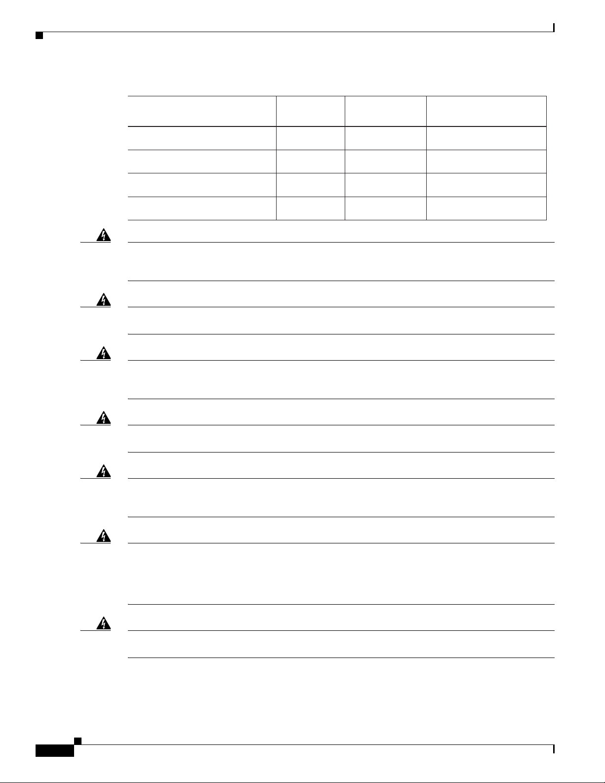
Standard Warning Statements
SM11 1200-1400 39-50 0.1-0.11
Fiber type and
Core diameter (µm)
Wavelength
(nm)
Max. Power
(mW)
Beam divergence
(rad)
MM62.5 1200-1400 150 0.18NA
MM50 1200-1400 135 0.17NA
SM11 1400-1600 112-145 0.11-0.13
349377
Chapter 2 Cisco 4000 Series ISRs Preinstallation
Warning
Warning
Warning
Warning
Warning
There is the danger of explosion if the battery is replaced incorrectly. Replace the battery only with
the same or equivalent type recommended by the manufacturer. Dispose of used batteries according
to the manufacturer’s instructions.
Do not touch or bridge the metal contacts on the battery. Unintentional discharge of the batteries can
cause serious burns.
To prevent personal injury or damage to the chassis, never attempt to lift or tilt the chassis using the
handles on modules (such as power supplies, fans, or cards); these types of handles are not designed
to support the weight of the unit.
To prevent the system from overheating, do not operate it in an area that exceeds the maximum
recommended ambient temperature of: 40 degrees C.
This equipment must be externally grounded using a customer-supplied ground wire before power is
applied. Contact the appropriate electrical inspection authority or an electrician if you are uncertain
that suitable grounding is available.
Statement 341
Statement 1015
Statement 1032
Statement 1047
Statement 366
Warning
Warning
Blank faceplates and cover panels serve three important functions: they prevent exposure to
hazardous voltages and currents inside the chassis; they contain electromagnetic interference (EMI)
that might disrupt other equipment; and they direct the flow of cooling air through the chassis. Do not
operate the system unless all cards, faceplates, front covers, and rear covers are in place.
1029
Only trained and qualified personnel should be allowed to install, replace, or service this equipment.
Statement 1030
Hardware Installation Guide for the Cisco 4000 Series Integrated Services Router
2-4
Statement
OL-32185-02
Page 59

Chapter 2 Cisco 4000 Series ISRs Preinstallation
Standard Warning Statements
Warning
Warning
Warning
Warning
Warning
This equipment must be installed and maintained by service personnel as defined by AS/NZS 3260.
Incorrectly connecting this equipment to a general-purpose outlet could be hazardous. The
telecommunications lines must be disconnected 1) before unplugging the main power connector or 2)
while the housing is open, or both.
Statement 1043
This unit might have more than one power supply connection. All connections must be removed to
de-energize the unit.
Statement 1028
Hazardous network voltages are present in WAN ports regardless of whether power to the unit is OFF
or ON. To avoid electric shock, use caution when working near WAN ports. When detaching cables,
detach the end away from the unit first.
Statement 1026
Before opening the unit, disconnect the telephone-network cables to avoid contact with
telephone-network voltages.
Statement 1041
Do not use this product near water; for example, near a bath tub, wash bowl, kitchen sink or laundry
tub, in a wet basement, or near a swimming pool.
Statement 1035
Warning
Warning
Warning
Warning
Warning
Warning
Never install telephone jacks in wet locations unless the jack is specifically designed for
wet locations.
No user-serviceable parts inside. Do not open.
Statement 1036
Statement 1073
Never touch uninsulated telephone wires or terminals unless the telephone line has been
disconnected at the network interface.
Statement 1037
Avoid using a telephone (other than a cordless type) during an electrical storm. There may be a remote
risk of electric shock from lightning.
To report a gas leak, do not use a telephone in the vicinity of the leak.
Statement 1038
Statement 1039
Instructed person is someone who has been instructed and trained by a skilled person and takes the
necessary precautions when working with equipment. Skilled person/Qualified personnel is
someone who has training or experience in the equipment technology and understand potential
hazards when working with equipment.
Statement 1089
OL-32185-02
Hardware Installation Guide for the Cisco 4000 Series Integrated Services Router
2-5
Page 60

Safety Recommendations
Chapter 2 Cisco 4000 Series ISRs Preinstallation
Warning
Warning
Warning
Warning
Only skilled person should be allowed to install, replace, or service this equipment. Refer to
statement 1089 for description of skilled person.
Only instructed person or skilled person should be allowed to install, replace, or service this
equipment. Refer to statement 1089 for description of skilled person.
This equipment must be grounded.To reduce the risk of electric shock, the power cord, plug or
combination must be connected to a properly grounded electrode, outlet or terminal.
1252—Equipment Grounding
Pluggable optical modules comply with IEC 60825-1 Ed. 3 and 21 CFR 1040.10 and 1040.11 with or
without exception for conformance with IEC 60825-1 Ed. 3 as described in Laser Notice No. 56, dated
May 8, 2019.
Statement 1255
Safety Recommendations
Before installing, configuring, or maintaining the router, review the safety warnings listed in Regulatory
Compliance and Safety Information for the Cisco 4000 Series ISRs guide that comes with your router.
Follow these guidelines to ensure general safety:
• Never attempt to lift an object that might be too heavy for you to lift by yourself.
Statement 1090
Statement 1091
Statement
• Keep the chassis area clear and dust-free during and after installation.
• If you remove the chassis cover, place it in a safe place.
• Keep tools and chassis components away from walk areas.
• Do not wear loose clothing that may get caught in the chassis. Fasten any tie or scarf and roll up
sleeves.
• Wear safety glasses when working under conditions that might be hazardous to your eyes.
• Do not perform any action that may create a hazard to people or makes equipment unsafe.
Safety with Electricity
Warning
Warning
This unit might have more than one power supply connection. All connections must be removed to
de-energize the unit.
Do not work on the system or connect or disconnect cables during periods of lightning activity.
Statement 1001
Statement 1028
2-6
Hardware Installation Guide for the Cisco 4000 Series Integrated Services Router
OL-32185-02
Page 61

Chapter 2 Cisco 4000 Series ISRs Preinstallation
Safety Recommendations
Warning
Warning
Read the installation instructions before connecting the system to the power source.
The covers are an integral part of the safety design of the product. Do not operate the unit without the
covers installed.
Statement 1077
Statement 1004
Follow these guidelines when working on equipment powered by electricity:
• Locate the emergency power-off switch in the room in which you are working. If an electrical
accident occurs, you can quickly turn off the power.
• Disconnect all power before doing the following:
–
Installing or removing a chassis
–
Working near power supplies
• Look carefully for possible hazards in your work area, such as moist floors, ungrounded power
extension cables, frayed power cords, and missing safety grounds.
• Do not work alone if hazardous conditions exist.
• Never assume that power is disconnected from a circuit. Always check.
• Never open the enclosure of the internal power supply.
• If an electrical accident occurs to another person, proceed as follows:
–
Use caution; do not become a victim yourself.
–
Turn off power to the device.
–
If possible, send another person to get medical aid. Otherwise, assess the condition of the victim
and then call for help.
–
Determine if the person needs rescue breathing or external cardiac compressions; then take
appropriate action.
In addition, use the following guidelines when working with any equipment that is disconnected from a
power source but has telephone wiring or other network cabling connections:
• Never install telephone wiring during a lightning storm.
• Never install telephone jacks in wet locations unless the jack is specifically designed for it.
• Never touch uninsulated telephone wires or terminals unless the telephone line is disconnected at
the network interface.
• Use caution when installing or modifying telephone lines.
• Remove power cables from all installed power supplies before opening the chassis.
Prevent Electrostatic Discharge Damage
Electrostatic discharge (ESD) can damage equipment and impair electrical circuitry. It can occur if
electronic printed circuit cards are improperly handled and can cause complete or intermittent failures.
Always follow these ESD prevention procedures when removing and replacing modules:
• Ensure that the router chassis is electrically connected to the ground.
OL-32185-02
Hardware Installation Guide for the Cisco 4000 Series Integrated Services Router
2-7
Page 62

General Site Requirements
• Wear an ESD-preventive wrist strap, ensuring that it makes good skin contact. Connect the clip to
an unpainted surface of the chassis frame to channel unwanted ESD voltages safely to ground. To
guard against ESD damage and shocks, the wrist strap and cord must operate effectively.
• If no wrist strap is available, ground yourself by touching a metal part of the chassis.
Caution For the safety of your equipment, periodically check the resistance value of the anti-static strap. It should
be between 1 and 10 megohms (Mohm).
General Site Requirements
This section describes the requirements your site must meet for the safe installation and operation of
your router. Ensure that the site is properly prepared before beginning installation. If you are
experiencing shutdowns or unusually high errors with your existing equipment, the guidelines provided
in this section can also help you isolate the cause of failures and prevent future problems.
Chapter 2 Cisco 4000 Series ISRs Preinstallation
General Precautions
Observe the following general precautions when using and working with your Cisco 4000 Series ISRs.
• Keep your system components away from radiators and heat sources, and do not block cooling vents.
• Do not spill food or liquids on your system components, and never operate the product in a wet
environment.
• Do not push any objects into the openings of your system components. Doing that can cause fire or
electric shock by shorting out interior components.
• Position system cables and power supply cables carefully. Route system cables and the power supply
cable and plug so that they cannot be stepped on or tripped over. Be sure that nothing else rests on
your system component cables or power cable.
• Do not modify power cables or plugs. Consult a licensed electrician or your power company for
electrical modifications at your site. Always follow your local and national wiring rules.
• If you turn off your system, wait at least 30 seconds before turning it on again to avoid system
component damage.
Site Selection Guidelines
Cisco 4000 Series ISRs require specific environmental operating conditions. Temperature, humidity,
altitude, and vibration can affect the performance and reliability of the router. The following sections
provide specific information to help you plan for the proper operating environment.
Cisco 4000 Series ISRs are designed to meet the industry EMC, safety, and environmental standards
described in the Regulatory Compliance and Safety Information for the Cisco 4000 Series ISRs
document.
2-8
Hardware Installation Guide for the Cisco 4000 Series Integrated Services Router
OL-32185-02
Page 63

Chapter 2 Cisco 4000 Series ISRs Preinstallation
Site Environmental Requirements
Environmental monitoring in the router protects the system and components from damage caused by
excessive voltage and temperature conditions. To ensure normal operation and avoid unnecessary
maintenance, plan and prepare your site configuration before installation. After installation, make sure
the site maintains the environmental characteristics as shown in Table 2-1.
Table 2-1 Router Environmental Tolerances
Environmental Characteristic Minimum Maximum
Steady State Operating 0 degree C 40 degree C
General Site Requirements
(40 degrees C at 10,000
feet)
Note Cisco 4461 ISR
can support
55C-6kft for a
limited list of SM
and NIM
deployments.
Storage –20 degrees C +70 degrees C
Humidity operating (noncondensing) 10% 90%
Humidity nonoperating (noncondensing) 5% 95%
Altitude operating: over allowable temperature
range (0 to 50 degrees C)
Altitude, nonoperating: over allowable temperature
range
Thermal shock non-operating with change over time
of 3 minute
Thermal Shock - Operating at 2.5 degree C per
minute
–500 feet 10,000 feet
–1000 feet 50,000 feet
–25 degrees C +70 degrees C
0 degrees C +50 degrees C
OL-32185-02
Hardware Installation Guide for the Cisco 4000 Series Integrated Services Router
2-9
Page 64

Rack Requirements
Physical Characteristics
Be familiar with the physical characteristics of the Cisco 4000 Series ISRs to assist you in placing the
system in the proper location.For more information on the physical characteristics of Cisco 4000 Series
Integrated Services Routers (ISRs), refer to the Cisco 4000 Series Integrated Services Routers datasheet.
The following list describes additional Cisco 4000 Series ISRs chassis characteristics:
• Cable-management brackets at each Cisco 4000 Series ISRs locations can hold 16 ports of
STP/UTP RJ 45 cables
• Cable-management brackets allow a bend radius of 1.5 inches for cables
• Rack-mount brackets that have optional mounting location. It allow you to mount on a front to rear
rail variance distance of 15.50/394mm to 19.00/482.6mm
Rack Requirements
Some Cisco routers include brackets for use with a 19-inch rack or, if specified in your order, optional
larger brackets for use with a 23-inch rack.
The following information can help you plan your equipment rack configuration:
Chapter 2 Cisco 4000 Series ISRs Preinstallation
• Allow clearance around the rack for maintenance.
• Allow at least one rack unit of vertical space between routers.
• Enclosed racks must have adequate ventilation. Ensure that the rack is not congested, because each
router generates heat. An enclosed rack should have louvered sides and a fan to provide cooling air.
Heat generated by equipment at the bottom of the rack can be drawn upward into the intake ports of
the equipment above it.
• When mounting a chassis in an open rack, ensure that the rack frame does not block the intake or
exhaust ports. If the chassis is installed on slides, check the position of the chassis when it is seated
in the rack.
Router Environmental Requirements
Cisco 4000 Series ISRss can be placed on a desktop or installed in a rack. The location of your router
and the layout of your equipment rack or wiring room are extremely important considerations for proper
operation. Equipment placed too close together, inadequate ventilation, and inaccessible panels can
cause malfunctions and shutdowns, and can make maintenance difficult. Plan for access to both front
and rear panels of the router.
When planning your site layout and equipment locations, refer to the “General Site Requirements”
section on page 2-8. If you are currently experiencing shutdowns or an unusually high number of errors
with your existing equipment, these precautions and recommendations may help you to isolate the cause
of failure and prevent future problems.
• Ensure that the room where your router operates has adequate air circulation. Electrical equipment
generates heat. Without adequate air circulation, ambient air temperature may not cool equipment
to acceptable operating temperatures.
• Always follow the ESD-prevention procedures described in the “Prevent Electrostatic Discharge
Damage” section on page 2-7 to avoid damage to equipment. Damage from static discharge can
cause immediate or intermittent equipment failure.
2-10
Hardware Installation Guide for the Cisco 4000 Series Integrated Services Router
OL-32185-02
Page 65

Chapter 2 Cisco 4000 Series ISRs Preinstallation
• Ensure that the chassis cover and module rear panels are secure. All empty network module slots,
interface card slots, and power supply bays must have filler panels installed. The chassis is designed
to allow cooling air to flow within it, through specially designed cooling slots. A chassis with
uncovered openings permits air leaks, which may interrupt and reduce the flow of air across internal
components.
• Baffles can help to isolate exhaust air from intake air. Baffles also help to draw cooling air through
the chassis. The best placement of the baffles depends on the airflow patterns in the rack. You can
find the best placement by experimenting with different configurations.
• When equipment installed in a rack (particularly in an enclosed rack) fails, try operating the
equipment individually. Power off other equipment in the rack (and in adjacent racks) to allow the
router under test maximum cooling air and clean power.
Power Guidelines and Requirements
Check the power at your site to ensure that you are receiving “clean” power (free of spikes and noise).
Install a power conditioner if necessary.
The AC power supply includes the following features:
Power Guidelines and Requirements
• Autoselects either 110 V or 220 V operation.
• All units include a 6-foot (1.8-meter) electrical power cord. (A label near the power inlet indicates
the correct voltage, frequency [only AC-powered systems], current draw, and power dissipation for
the unit.)
Table 2-2 lists power requirements for the Cisco 4000 Series ISRs.
Table 2-2 Power Requirements for Cisco 4000 Series ISRs
Router Power Source Input Power Input Voltage
Tolerance Limits
Cisco 4461 ISR AC 100 — 240 VAC, 8.2 A, 50 — 60 Hz 90 — 264 VAC
Cisco 4461 with PoE AC 100 — 240 VAC, 11.0 A, 50 — 60 Hz 90 — 264 VAC
Cisco 4451 ISR AC 100 — 240 VAC, 5.3 A, 50 — 60 Hz 90 — 264 VAC
Cisco 4451 with PoE AC 100 — 240 VAC, 11.0 A, 50 — 60 Hz 90 — 264 VAC
Cisco 4431 ISR AC 100 — 240 VAC, 5.3 A, 50 — 60 Hz 90 — 264 VAC
Cisco 4351 ISR AC 100 — 240 VAC, 11.0 A, 50 — 60 Hz 90 — 264 VAC
Cisco 4331 ISR AC 100 — 240 VAC, 50 — 60 Hz 90 — 264 VAC
Cisco 4321ISR AC 100 — 240 VAC, 50 — 60 Hz 90 — 264 VAC
Cisco 4221 ISR AC 100 — 240 VAC, 50 — 60 Hz 90 — 264 VAC
Network Cabling Specifications
The following sections describe the cables required to install your Cisco 4000 Series ISRs:
• Console and Auxiliary Port Considerations, page 2-12
• Prepare for Network Connections, page 2-14
Hardware Installation Guide for the Cisco 4000 Series Integrated Services Router
OL-32185-02
2-11
Page 66

Network Cabling Specifications
Console and Auxiliary Port Considerations
The router includes an asynchronous serial console port and an auxiliary port. You access to the router
either locally using a console terminal connected to the console port, or remotely using a modem
connected to the auxiliary port. This section discusses important cabling information you must consider
before connecting the router to a console terminal or modem.
The major difference between the console and auxiliary ports is that the auxiliary port supports hardware
flow control and the console port does not. Flow control paces the transmission of data between a
sending and a receiving device. Flow control ensures that the receiving device can absorb the data sent
to it before the sending device sends more data. When the buffers on the receiving device are full, a
message is sent to the sending device to suspend transmission until the data in the buffers is processed.
Because the auxiliary port supports flow control, it is suited for use with the high-speed transmissions
of a modem. Console terminals send data at speeds slower than the speeds modems do; therefore, the
console port is ideally suited for use with console terminals.
Note Cisco 4221 ISR does not have an auxiliary port.
Chapter 2 Cisco 4000 Series ISRs Preinstallation
Console Port Connections
The router has both EIA/TIA-232 asynchronous (RJ-45) and USB 5-pin mini Type B, 2.0 compliant
serial console ports. Shielded USB cables with properly terminated shields are recommended.
EIA/TIA-232
Depending on the cable and the adapter used, this port appears as a DTE or DCE device at the end of the
cable. At a time, only one port can be used.
The default parameters for the console port are 9600 baud, 8 data bits, 1 stop bit, and no parity. The
console port does not support hardware flow control. For detailed information about installing a console
terminal, see the “Connect to Console Terminal or Modem” section on page 3-23.
For cable and port pinouts, see the Cisco Modular Access Router Cable Specifications document.
USB Serial Console
The USB serial console port connects directly to the USB connector of a PC using a USB Type A to 5-pin
mini USB Type-B cable. The USB Console supports full speed (12Mb/s) operation. The console port
does not support hardware flow control.
Note Cisco 4461 supports Mini-USB Type B serial port and Micro-USB Type B serial port
2-12
Note Always use shielded USB cables with a properly terminated shield.
The default parameters for the console port are 9600 baud, 8 data bits, no parity, and 1 stop bit. For
detailed information about installing a console terminal, see the “Connect to Console Terminal or
Modem” section on page 3-23.
Hardware Installation Guide for the Cisco 4000 Series Integrated Services Router
OL-32185-02
Page 67

Chapter 2 Cisco 4000 Series ISRs Preinstallation
For operation with a Microsoft Windows OS version older than Windows 7, the Cisco Windows USB
console driver must be installed on a PC connected to the console port. If the driver is not installed,
appropriate prompts guide you through a simple installation process. For detailed information about
installing the Cisco Windows USB Console Driver, see “Install Cisco Microsoft Windows USB Device
Driver” section on page 3-25.
The Cisco Windows USB Console Driver allows plugging and unplugging the USB cable from the
console port without affecting Windows HyperTerminal operations. No special drivers are needed for
Mac OS X or Linux.
At a time, only one console port can be active. When a cable is plugged into the USB console port, the
RJ-45 port becomes inactive. Conversely, when the USB cable is removed from the USB port, the RJ-45
port becomes active.
Baud rates for the USB console port are 1200, 2400, 4800, 9600, 19200, 38400, 57600, and 115200 bps.
Note 4-pin mini USB Type-B connectors might be easily confused with 5-pin mini USB Type-B
connectors. Only the 5-pin mini USB Type-B is supported.
USB Console OS Compatibility
• Windows 8, Windows 7, Windows 2000, Window XP 32 bit, Windows Vista 32 bit
Network Cabling Specifications
• Mac OS X version 10.5.4
• Redhat / Fedora Core 10 with kernel 2.6.27.5-117
• Ubuntu 8.10 with kernel 2.6.27-11
• Debian 5.0 with kernel 2.6
• Suse 11.1 with kernel 2.6.27.7-9
Auxiliary Port Connections
The router has an EIA/TIA-232 asynchronous serial auxiliary port (RJ-45) that supports flow control.
Depending on the cable and the adapter used, this port appears as a DTE or DCE device at the end of the
cable.
For connection to a modem, you must use an RJ-45-to-DB-25 adapter cable. This cable is orderable
separately along with a DB-9-to-DB-25 adapter.
For detailed information about connecting devices to the auxiliary port, see the “Connect to Console
Terminal or Modem” section on page 3-23.
For cable and port pinouts, see the Cisco Modular Access Router Cable Specifications document.
OL-32185-02
Hardware Installation Guide for the Cisco 4000 Series Integrated Services Router
2-13
Page 68

Required Tools and Equipment for Installation and Maintenance
Prepare for Network Connections
When setting up your router, consider distance limitations and potential electromagnetic interference
(EMI) as defined by the applicable local and international regulations.
Network connection considerations are provided for:
• Ethernet Connections, page 2-14
See the following online document for more information about network connections and interfaces:
• Cisco Modular Access Router Cable Specifications
Chapter 2 Cisco 4000 Series ISRs Preinstallation
Warning
To avoid electric shock, do not connect safety extra-low voltage (SELV) circuits to telephone-network
voltage (TNV) circuits. LAN ports contain SELV circuits, and WAN ports contain TNV circuits. Some
LAN and WAN ports both use RJ-45 connectors.
Statement 1021
Ethernet Connections
The IEEE has established the Ethernet IEEE 802.3 Standards. The routers support the following Ethernet
implementations:
• 1000BASE-T—1000 Mb/s full-duplex transmission over a Category 5 or better unshielded
twisted-pair (UTP) cable. Supports the Ethernet maximum length of 328 feet (100 meters).
• 100BASE-T—100 Mb/s full-duplex transmission over a Category 5 or better unshielded
twisted-pair (UTP) cable. Supports the Ethernet maximum length of 328 feet (100 meters).
• 10BASE-T—10 Mb/s full-duplex transmission over a Category 5 or better unshielded twisted-pair
(UTP) cable. Supports the Ethernet maximum length of 328 feet (100 meters).
• 10GBASE—Cisco 4461 supports 10GE full-duplex.
For information about Ethernet cables, connectors, and pinouts, see the Cisco Modular Access Router
Cable Specifications document.
Required Tools and Equipment for Installation and Maintenance
2-14
Warning
Warning
Hardware Installation Guide for the Cisco 4000 Series Integrated Services Router
Only trained and qualified personnel should be allowed to install, replace, or service this equipment.
Statement 1030
This equipment must be installed and maintained by service personnel as defined by AS/NZS 3260.
Incorrectly connecting this equipment to a general-purpose outlet could be hazardous. The
telecommunications lines must be disconnected 1) before unplugging the main power connector or 2)
while the housing is open, or both.
Statement 1043
OL-32185-02
Page 69

Chapter 2 Cisco 4000 Series ISRs Preinstallation
You need the following tools and equipment to install and upgrade the router and its components:
• ESD-preventive cord and wrist strap
• Number 2 Phillips screwdriver
• Phillips screwdrivers: small, 3/16-in. (4 to 5 mm) and medium, 1/4-in. (6 to 7 mm)
–
To install or remove modules
–
To remove the cover, if you are upgrading memory or other components
• Screws that fit your rack
• Wire crimper
• Wire for connecting the chassis to an earth ground:
–
AWG 6 (13 mm2) wire for NEBS-compliant chassis grounding
–
AWG 14 (2 mm2) or larger wire for NEC-compliant chassis grounding
–
AWG 10 (4 mm2) or larger wire for EN/IEC 60950-1 and EN/IEC 62368-1 compliant chassis
grounding
• For NEC-compliant grounding, an appropriate user-supplied ring terminal, with an inner diameter
of 1/4 in. (5 to 7 mm)
In addition, depending on the type of modules you plan to use, you might need the following equipment
to connect a port to an external network:
Required Tools and Equipment for Installation and Maintenance
• Cables for connection to the WAN and LAN ports (dependent on configuration)
Note For more information on cable specifications, see the Cisco Modular Access Router Cable
Specifications document at cisco.com.
• Ethernet hub or PC with a network interface card for connection to an Ethernet (LAN) port.
• Console terminal (an ASCII terminal or a PC running HyperTerminal or similar terminal emulation
software) configured for 9600 baud, 8 data bits, 1 stop bit, no flow control, and no parity.
• Modem for connection to the auxiliary port for remote administrative access (optional).
• Data service unit (DSU) or channel service unit/data service unit (CSU/DSU) as appropriate for
serial interfaces.
• External CSU for any CT1/PRI modules without a built-in CSU.
OL-32185-02
Hardware Installation Guide for the Cisco 4000 Series Integrated Services Router
2-15
Page 70

Installation Checklist
Installation Checklist
The sample installation checklist lists items and procedures for installing a new router. Make a copy of
this checklist and check the tasks when completed. For each router in the site, maintain a copy of the
checklist in your site log (described in the next section, “Creating a Site Log”).
Installation checklist for site_____________________________________________
Router name_______________________________________________________
Task Verified by Date
Installation checklist copied
Background information placed in Site Log
Site power voltages verified
Installation site power check completed
Required tools available
Additional equipment available
Router received
Router quick start guide received
Regulatory Compliance and Safety Information for the
Cisco 4000 Series ISRs document received
Product registration card received
Cisco.com contact information label received
Chassis components verified
Initial electrical connections established
ASCII terminal (for local configuration) or
modem (for remote configuration) available
Signal distance limits verified
Startup sequence steps completed
Initial operation verified
Software image verified
Chapter 2 Cisco 4000 Series ISRs Preinstallation
2-16
Hardware Installation Guide for the Cisco 4000 Series Integrated Services Router
OL-32185-02
Page 71

Chapter 2 Cisco 4000 Series ISRs Preinstallation
Creating a Site Log
The Site log provides a record of all actions performed at all routers in the site. Keep it in an accessible
place near the chassis those who perform regular tasks have access to it. In this log, maintain the
installation checklist to verify steps in the installation and maintenance of the router. Site log entries may
include the following information:
• Installation progress: Make a copy of the installation checklist and file it in the site log. Check tasks
as each procedure is completed.
• Upgrade and maintenance procedures: Use the site log as a record of ongoing router maintenance
and expansion.
• A site log may include the following events:
–
Installation of network modules
–
Removal or replacement of network modules and other upgrades
–
Configuration changes
–
Maintenance schedules and requirements
–
Intermittent problems
Creating a Site Log
–
Comments and notes
.
OL-32185-02
Hardware Installation Guide for the Cisco 4000 Series Integrated Services Router
2-17
Page 72

Creating a Site Log
Chapter 2 Cisco 4000 Series ISRs Preinstallation
2-18
Hardware Installation Guide for the Cisco 4000 Series Integrated Services Router
OL-32185-02
Page 73

Warning
CHAPTER
3
Install and Connect Cisco 4000 Series ISRs
This chapter describes how to install and connect Cisco 4000 Series Integrated Services Routers (ISRs)
to LAN, WAN, and Voice networks. The following sections provide technical details.
• Install the Router, page 3-5
• Chassis Grounding, page 3-20
• Connect Power, page 3-21
• Connect to Console Terminal or Modem, page 3-23
• Install Cisco Microsoft Windows USB Device Driver, page 3-25
• Uninstall Cisco Microsoft Windows USB Driver, page 3-27
• Connect WAN, LAN, and Voice Interfaces, page 3-28
To reduce the risk of electric shock, secure the modules with provided screws
. Statement 347
Warning
Warning
Warning To see translations of the warnings that appear in this publication, see the Regulatory Compliance and
Warning
To reduce the risk of electric shock, the chassis of this equipment needs to be connected to
permanent earth ground during normal use.
To reduce risk of electric shock and fire, a readily accessible two-poled disconnect device must be
incorporated in the fixed wiring
Safety Information for the Cisco 4000 Series ISRs document.
should be allowed to install, replace, or service this equipment.
This unit might have more than one power supply connection. All connections must be removed to
de-energize the unit.
Statement 1028
. Statement 1022
Statement CS-0445
Only trained and qualified personnel
Statement 1030
OL-32185-02
Hardware Installation Guide for Cisco 4000 Series Integrated Services Routers
3-1
Page 74

Chapter 3 Install and Connect Cisco 4000 Series ISRs
Warning
Warning
Warning
Warning
Warning
Blank faceplates and cover panels serve three important functions: they prevent exposure to
hazardous voltages and currents inside the chassis; they contain electromagnetic interference (EMI)
that might disrupt other equipment; and they direct the flow of cooling air through the chassis. Do not
operate the system unless all cards, faceplates, front covers, and rear covers are in place.
Statement
1029
Hazardous network voltages are present in WAN ports regardless of whether power to the unit is OFF
or ON. To avoid electric shock, use caution when working near WAN ports. When detaching cables,
detach the end away from the unit first.
Statement 1026
This equipment must be grounded. Never defeat the ground conductor or operate the equipment in the
absence of a suitably installed ground conductor. Contact the appropriate electrical inspection
authority or an electrician if you are uncertain that suitable grounding is available.
Statement 1024
Before opening the unit, disconnect the telephone-network cables to avoid contact with
telephone-network voltages.
Statement 1041
Do not use this product near water; for example, near a bath tub, wash bowl, kitchen sink or laundry
tub, in a wet basement, or near a swimming pool.
Statement 1035
Warning
Warning
Warning
Warning
Warning
Never install telephone jacks in wet locations unless the jack is specifically designed for
wet locations.
Statement 1036
Never touch uninsulated telephone wires or terminals unless the telephone line has been
disconnected at the network interface.
Statement 1037
Avoid using a telephone (other than a cordless type) during an electrical storm. There may be a remote
risk of electric shock from lightning.
To report a gas leak, do not use a telephone in the vicinity of the leak.
Statement 1038
Statement 1039
This unit is intended for installation in restricted access areas. A restricted access area can be
accessed only through the use of a special tool, lock and key, or other means of security.
Statement 1017
3-2
Hardware Installation Guide for Cisco 4000 Series Integrated Services Routers
OL-32185-02
Page 75

Chapter 3 Install and Connect Cisco 4000 Series ISRs
Before You Begin
Warning
Warning
Warning
Warning
Warning
Blank faceplates and cover panels serve three important functions: they prevent exposure to
hazardous voltages and currents inside the chassis; they contain electromagnetic interference (EMI)
that might disrupt other equipment; and they direct the flow of cooling air through the chassis. Do not
operate the system unless all cards, faceplates, front covers, and rear covers are in place.
Statement 1029
The covers are an integral part of the safety design of the product. Do not operate the unit without the
covers installed.
Instructed person is someone who has been instructed and trained by a skilled person and takes the
necessary precautions when working with equipment. Skilled person/Qualified personnel is
someone who has training or experience in the equipment technology and understand potential
hazards when working with equipment.
Only skilled person should be allowed to install, replace, or service this equipment. Refer to
statement 1089 for description of skilled person.
Only instructed person or skilled person should be allowed to install, replace, or service this
equipment. Refer to statement 1089 for description of skilled person.
Statement 1077
Statement 1089
Statement 1090
Statement 1091
Warning
This equipment must be grounded.To reduce the risk of electric shock, the power cord, plug or
combination must be connected to a properly grounded electrode, outlet or terminal.
1252—Equipment Grounding
Before You Begin
Before installing and connecting a Cisco 4000 Series Integrated Services Router, read the safety
warnings and gather the following tools and equipment.
• ESD-preventive cord and wrist strap
• Number 2 Phillips screwdriver
• Flat-blade screwdrivers: small, 3/16-in. (4 to 5 mm) and medium, 1/4-in. (6 to 7 mm)
–
To install or remove modules
–
To remove the cover, if you are upgrading memory or other components
• Screws that fit your rack
• Wire crimper
• Wire for connecting the chassis to an earth ground:
–
AWG 6 (13 mm) wire for NEBS-compliant chassis grounding
–
AWG 14 (2 mm) or larger wire for NEC-compliant chassis grounding
Statement
OL-32185-02
Hardware Installation Guide for Cisco 4000 Series Integrated Services Routers
3-3
Page 76

Unpack the Router
Chapter 3 Install and Connect Cisco 4000 Series ISRs
–
AWG 18 (1 mm) or larger wire for EN/IEC 60950-compliant chassis grounding
• For NEC-compliant grounding, an appropriate user-supplied ring terminal, with an inner diameter
of 1/4 in. (5 to 7 mm)
In addition, depending on the type of modules you plan to use, you might need the following equipment
to connect a port to an external network:
• Cables for connection to the WAN and LAN ports (dependent on configuration)
Note For more information on cable specifications, see the Cisco Modular Access Router Cable
Specifications document at cisco.com.
• Ethernet hub or PC with a network interface card for connection to an Ethernet (LAN) port.
• Console terminal (an ASCII terminal or a PC running HyperTerminal or similar terminal emulation
software) configured for 9600 baud, 8 data bits, 1 stop bit, no flow control, and no parity.
• Modem for connection to the auxiliary port for remote administrative access (optional).
• Data service unit (DSU) or channel service unit/data service unit (CSU/DSU) as appropriate for
serial interfaces.
• External CSU for any CT1/PRI modules without a built-in CSU.
Also, you need to have access to the following:
CLI Console Access
Use the USB or RJ-45 console port on the router to access the Cisco Internet Operating System
(IOS-XE) command line interface (CLI) on the router and to perform configuration tasks. A terminal
emulation program is required to establish communication between the router and a PC. See the
“Connect to Console Terminal or Modem” section on page 3-23 for instructions.
Note A Microsoft Windows USB driver must be installed before you establish physical connectivity
between the router and the PC.
Slot and Port Numbers
The routers have built in ports and new slots. The new slots accommodate new modules and interface
cards; SM-Xs, NIMs, ISCs, PVDM4s, and the Cisco E-Series Server modules. See the “Slots, Subslots
(Bay), Ports, and Interfaces in Cisco 4000 Series ISRs” section on page 1-40 for slot and port numbering.
Software Licenses
To install features on the router, you must purchase a software package. See the “Licensing” section of
the Software Configuration Guide for the Cisco 4400 and Cisco 4300 Series ISRs.
Unpack the Router
Do not unpack the router until you are ready to install it. If the final installation site is not ready as yet,
keep the chassis in its shipping container to prevent accidental damage. When you are ready to install
the router, unpack it.
3-4
Hardware Installation Guide for Cisco 4000 Series Integrated Services Routers
OL-32185-02
Page 77

Chapter 3 Install and Connect Cisco 4000 Series ISRs
The router, accessory kit, publications, and any optional equipment you ordered may be shipped in more
than one container. When you unpack the containers, check the packing list to ensure that you received
all of the items on the list.
Install the Router
If you need to install Network Interface Modules (NIMs), Service Modules (SMs), and
Field-Replaceable Units (FRUs), you can install them either before or after you install the router. Ideally,
you install modules when you have the best access to the back panel of the router. Internal modules and
FRUs, such as SMs, NIMs or Packet Voice Digital Signal Processor Module (PVDM4s), Compact Flash
Cards, and fan trays should be installed before rack-mounting.
You can install the Cisco 4000 Series Integrated Services Routers in one of the following ways:
• Set the router chassis on a desktop
• Attach the router chassis to the wall (Cisco 4461, 4451, and 4351 ISRs do not support wall
mounting.)
• Mount the router chassis in a rack
Install the Router
Warning
Caution To prevent damage to the chassis, never attempt to lift or tilt the chassis by holding it by the plastic panel
Before working on a system that has an On/Off switch, turn OFF the power and unplug the power cord.
Statement 1.
on the front. Always hold the chassis by the sides of the metal body.
Set Chassis on Desktop
You can place the router on a desktop, bench top, or shelf.
Note Do not set the chassis in an area where high acoustic noise can be an issue.
Warning
Caution Do not place anything on top of the router that weighs more than 10 pounds (4.5 kg), and do not stack
To prevent personal injury or damage to the chassis, never attempt to lift or tilt the chassis using the
handles on modules (such as power supplies, fans, or cards); these types of handles are not designed
to support the weight of the unit.
routers on a desktop. Excessive distributed weight of more than 10 pounds, or pound point load of
10 pounds on top could damage the chassis.
Statement 1032.
OL-32185-02
Caution Your chassis installation must allow unrestricted airflow for chassis cooling. For placing the router on a
desktop, keep at least 1 inch (2.54 cm) of clear space beside the cooling inlet and exhaust vents.
Hardware Installation Guide for Cisco 4000 Series Integrated Services Routers
3-5
Page 78

Install the Router
After the router is installed, you must connect the chassis to a reliable earth ground. For the chassis
ground connection procedures, see the “Chassis Grounding” section on page 3-20.
Attach Chassis to Wall or Mount Chassis in Rack
The tasks that you perform for attaching the router chassis to the wall, or for mounting it in a rack, are
based on the specific model of the Cisco 4000 Series Integrated Service Router.
See the relevant installation sub-section for your specific router in the Cisco 4000 Series ISRs:
• Install Cisco 4400 or 4300 ISR
• Install Cisco 4200 Series ISR
Install Cisco 4400 or 4300 ISR
This section describes the installation procedure that is common for all Cisco 4400 and 4300 Series ISRs.
Note For illustration purposes, we have used images of Cisco 4400 Series ISRs in all figures. You cannot wall
mount the Cisco 4461, 4451, and 4351 ISR as these routers do not support wall mounting.
Chapter 3 Install and Connect Cisco 4000 Series ISRs
Attach Cisco 4400 or 4300 ISR Chassis to Wall
Step 1 Attach the wall-mounting brackets to the router chassis as shown in Figure 3-1 using the four PHMS
screws and the plastic spacers provided for each bracket.
3-6
Hardware Installation Guide for Cisco 4000 Series Integrated Services Routers
OL-32185-02
Page 79

Chapter 3 Install and Connect Cisco 4000 Series ISRs
1
1
2
3
2
Figure 3-1 Bracket Installation for Wall Mounting (Cisco 4431 ISR shown)
Install the Router
1 Machine screws (included in install kit) 2 Plastic spacers (included)
3 Wall-mounting hardware (customer
supplied)
OL-32185-02
Caution Do not over-torque the screws. The recommended torque is 15 to 18 inch-lb (1.7 to 2.0 N-m).
Hardware Installation Guide for Cisco 4000 Series Integrated Services Routers
3-7
Page 80

Install the Router
Note To attach to a wall stud, each bracket requires one number-10 wood screws (round- or pan-head) with
Note For hollow-wall mounting, each bracket requires two wall anchors with washers. Wall anchors and
Caution Your chassis installation must allow unrestricted airflow for chassis cooling.
Step 2 Attach the router to the wall using the brackets.
Note If you prefer, you can also install the router diagonally using the other two sides.
Chapter 3 Install and Connect Cisco 4000 Series ISRs
number-10 washers, or two number-10 washer-head screws. The screws must be long enough to
penetrate at least 1.5 inches (38.1 mm) into the supporting wood or metal wall stud.
washers must be size number 10. Route the cables so that they do not put a strain on the connectors or
mounting hardware.
After the router is installed, you must connect the chassis to a reliable earth ground. For the chassis
ground connection procedures, see the “Chassis Grounding” section on page 3-20.
Mount Cisco 4400 or 4300 ISR Chassis in Rack
Warning If the rack is provided with stabilizing devices, install the stabilizers before mounting or servicing the unit in the rack.
Statement 1006
Warning
Warning
Note Cisco 4461 ISR can operate in an area with an ambient temperature of 55 degrees C.
This equipment must be grounded. Never defeat the ground conductor or operate the equipment in the
absence of a suitably installed ground conductor. Contact the appropriate electrical inspection
authority or an electrician if you are uncertain that suitable grounding is available.
To prevent the system from overheating, do not operate it in an area that exceeds the maximum
recommended ambient temperature of: 40 degrees C.
Statement 1024
Statement 1047
3-8
Cisco 4000 Series ISRs can be installed in 19-inch (48.26-cm) EIA and 23-inch (58.42-cm)
Southwestern Bell Corporation (SBC) racks. Cisco 4000 Series ISRs can also be mounted in a 600-mm
ETSI rack. Use the standard brackets shipped with the router for mounting the chassis in a 19-inch EIA
rack; you can order optional larger brackets for mounting the chassis in a 23-inch SBC rack.
You can mount the router in the following ways:
• Center-front mounting: Brackets attached in the center front of the chassis with only the front panel
facing forward.
Hardware Installation Guide for Cisco 4000 Series Integrated Services Routers
OL-32185-02
Page 81

Chapter 3 Install and Connect Cisco 4000 Series ISRs
1
2
302953
1
2
• Center-back mounting: Brackets attached in the center back of the chassis with only the back panel
facing forward.
• Front mounting: Brackets attached at the front of the chassis with the front panel facing forward.
• Back mounting: Brackets attached at the back of the chassis with the back panel facing forward.
Step 1 Attach the mounting brackets to the router chassis as shown in Figure 3-2 through Figure 3-5, using the
screws provided.
Caution Do not over-torque the screws. The recommended torque is 15 to 18 inch-lb (1.7 to 2.0 N-m).
Attach the second bracket to the opposite side of the chassis. Use a number-2 Phillips screwdriver to
install the number-8 bracket screws.
Caution Your chassis installation must allow unrestricted airflow for chassis cooling.
Figure 3-2 Bracket Installation for Front Mounting (Cisco 4451-X ISR shown)
Install the Router
1 23-inch SBC1 brackets
1. Southwestern Bell Corporation (SBC)
OL-32185-02
2 19-inch EIA brackets
Hardware Installation Guide for Cisco 4000 Series Integrated Services Routers
3-9
Page 82

Chapter 3 Install and Connect Cisco 4000 Series ISRs
1
2
302954
1
2
Install the Router
Figure 3-3 Bracket Installation for Center-Front Mounting (Cisco 4451-X ISR shown)
1 23-inch SBC brackets 2 19-inch EIA brackets
Step 2 Use the screws provided with the rack to install the chassis in the rack. (See Figure 3-4 and Figure 3-6.)
For both the 19-inch EIA brackets and the 23-inch SBC brackets, start the lower pair of screws first, and
rest the brackets on the lower screws while you insert the upper pair of screws.
Tip The screw slots in the brackets are spaced to line up with every second pair of screw holes in the rack.
When the correct screw holes are used, the small, threaded holes in the brackets line up with unused
screw holes in the rack. If the small holes do not line up with the rack holes, you must raise or lower the
brackets to the next rack hole.
Warning
To prevent bodily injury when mounting or servicing this unit in a rack, you must take special
precautions to ensure that the system remains stable. The following guidelines are provided to
ensure your safety:
• This unit should be mounted at the bottom of the rack if it is the only unit in the rack.
• When mounting this unit in a partially filled rack, load the rack from the bottom to the top with the heaviest
component at the bottom of the rack.
• If the rack is provided with stabilizing devices, install the stabilizers before mounting or servicing the unit in
the rack.
Statement 1006
3-10
Warning
To prevent personal injury or damage to the chassis, never attempt to lift or tilt the chassis using the
handles on modules (such as power supplies, fans, or cards); these types of handles are not designed
to support the weight of the unit.
Hardware Installation Guide for Cisco 4000 Series Integrated Services Routers
Statement 1032
OL-32185-02
Page 83

Chapter 3 Install and Connect Cisco 4000 Series ISRs
Caution Be sure to leave some space above and below each router in a rack to allow for cooling air circulation.
Figure 3-4 Bracket Installation for Back Mounting (Cisco 4451-X ISR shown)
Install the Router
302955
1
2
1 23-inch SBC brackets 2 19-inch EIA brackets
Figure 3-5 Bracket Installation for Center-Back Mounting (Cisco 4451-X ISR shown)
1
2
2
1
302956
1 23-inch SBC brackets 2 19-inch EIA brackets
Hardware Installation Guide for Cisco 4000 Series Integrated Services Routers
OL-32185-02
2
1
3-11
Page 84

Install the Router
302995
1
Chapter 3 Install and Connect Cisco 4000 Series ISRs
Figure 3-6 shows a typical installation in a rack.
Figure 3-6 Mounting the Chassis in a Rack (Typical)
PS
302994
1
1 Mounting screws (4)
Figure 3-7 shows an installation with a chassis rear-forward.
Figure 3-7 Mounting the Chassis in a Rack, Rear Forward (Cisco 4451-X ISR shown)
3-12
1 Mounting screws (4)
After the router is installed, you must connect the chassis to a reliable earth ground. For the chassis
ground connection procedures, see the “Chassis Grounding” section on page 3-20.
Hardware Installation Guide for Cisco 4000 Series Integrated Services Routers
OL-32185-02
Page 85

Chapter 3 Install and Connect Cisco 4000 Series ISRs
385297
1
Install Cisco 4200 Series ISR
This section describes the installation procedure that is common for all Cisco 4200 Series ISRs.
Note For illustration purposes, we have used images of Cisco 4221 ISR in all figures.
Attach Cisco 4200 ISR Chassis to Wall
Step 1 Attach the wall-mounting brackets to the router chassis as shown in Figure 3-8 using the four PHMS
screws and the plastic spacers provided for each bracket.
Figure 3-8 Bracket Installation for Wall Mounting (Cisco 4221 ISR shown)
Install the Router
OL-32185-02
1 Machine screws
Hardware Installation Guide for Cisco 4000 Series Integrated Services Routers
3-13
Page 86

Install the Router
Note Do not over-torque the screws. The recommended torque is 15 to 18 inch-lb (1.7 to 2.0 N-m).
Note To attach to a wall stud, each bracket requires one number-10 wood screws (round- or pan-head) with
Note For hollow-wall mounting, each bracket requires two wall anchors with washers. Wall anchors and
Note Your chassis installation must allow unrestricted airflow for chassis cooling.
Chapter 3 Install and Connect Cisco 4000 Series ISRs
number-10 washers, or two number-10 washer-head screws. The screws must be long enough to
penetrate at least 1.5 inches (38.1 mm) into the supporting wood or metal wall stud.
washers must be size number 10. Route the cables so that they do not put a strain on the connectors or
mounting hardware.
Step 2 Attach the router to the wall using the brackets.
After the router is installed, you must connect the chassis to a reliable earth ground. For the chassis
ground connection procedures, see the “Chassis Grounding” section on page 3-20.
Mount Cisco 4200 ISR Chassis in Rack
Step 1 Attach the brackets to the router chassis (towards the front or back) as shown in Figure 3-10.
3-14
Hardware Installation Guide for Cisco 4000 Series Integrated Services Routers
OL-32185-02
Page 87

Chapter 3 Install and Connect Cisco 4000 Series ISRs
2
1
1
2
Figure 3-9 Bracket Installation for Front Mounting (Cisco 4221 ISR shown)
Install the Router
1 Mounting Screws 2 23-inch SBC brackets
Step 2
Use the screws provided with the rack to install the chassis in the rack. (See Figure 3-10.)
Hardware Installation Guide for Cisco 4000 Series Integrated Services Routers
OL-32185-02
3-15
Page 88

Install the Router
2
1
3
Chapter 3 Install and Connect Cisco 4000 Series ISRs
Figure 3-10 Bracket Installation for Back Mounting
3-16
1 Screws 2 23-inch SBC brackets
Warning
Hardware Installation Guide for Cisco 4000 Series Integrated Services Routers
To prevent bodily injury when mounting or servicing this unit in a rack, you must take special
precautions to ensure that the system remains stable. The following guidelines are provided to
ensure your safety:
• This unit should be mounted at the bottom of the rack if it is the only unit in the rack.
• When mounting this unit in a partially filled rack, load the rack from the bottom to the top with the heaviest
component at the bottom of the rack.
• If the rack is provided with stabilizing devices, install the stabilizers before mounting or servicing the unit in
the rack.
Statement 1006
OL-32185-02
Page 89

Chapter 3 Install and Connect Cisco 4000 Series ISRs
Install the Router
Warning
To prevent personal injury or damage to the chassis, never attempt to lift or tilt the chassis using the
handles on modules (such as power supplies, fans, or cards); these types of handles are not designed
to support the weight of the unit.
Caution Be sure to leave some space above and below each router in a rack to allow for cooling air circulation.
After the router is installed, you must connect the chassis to a reliable earth ground. For the chassis
ground connection procedures, see the “Chassis Grounding” section on page 3-20.
Mount Cisco 4200 ISR Chassis in Rack with AC Power Unit
Step 1 Attach the brackets to the router chassis (towards the left or right) as shown in Figure 3-11 and
Figure 3-12.
Statement 1032
OL-32185-02
Hardware Installation Guide for Cisco 4000 Series Integrated Services Routers
3-17
Page 90

Chapter 3 Install and Connect Cisco 4000 Series ISRs
385355
2
1
3
4
1
Install the Router
Figure 3-11 AC Power Bracket Installation for Left Mounting (Cisco 4221 ISR shown)
1 Mounting Screws 2 AC power supply unit installation module
3 23-inch SBC brackets 4 19-inch SBC brackets
Hardware Installation Guide for Cisco 4000 Series Integrated Services Routers
3-18
OL-32185-02
Page 91

Chapter 3 Install and Connect Cisco 4000 Series ISRs
385357
1
3
2
Figure 3-12 AC Power Bracket Installation for Right Mounting (Cisco 4221 ISR shown)
Install the Router
1 23-inch SBC brackets 2 19-inch SBC brackets
3 AC power supply unit installation module
OL-32185-02
Hardware Installation Guide for Cisco 4000 Series Integrated Services Routers
3-19
Page 92

Chassis Grounding
After the router is installed, you must connect the chassis to a reliable earth ground. For the chassis
ground connection procedures, see the “Chassis Grounding” section on page 3-20.
Chassis Grounding
Chapter 3 Install and Connect Cisco 4000 Series ISRs
Warning
Warning
This equipment must be grounded. Never defeat the ground conductor or operate the equipment in the
absence of a suitably installed ground conductor. Contact the appropriate electrical inspection
authority or an electrician if you are uncertain that suitable grounding is available.
During this procedure, wear grounding wrist straps to avoid ESD damage to the card. Do not directly
touch the backplane with your hand or any metal tool, you could shock yourself.
Statement 1024
Statement 94
You must connect the chassis to a reliable earth ground; the ground wire must be installed in accordance
with local electrical safety standards.
• For grounding, use size 6 AWG (13 mm
2
) copper wire and the ground lug provided in the accessory
kit.
Note This equipment is suitable for installation in Network Telecommunications Facilities and
locations where the NEC applies. The equipment is suitable for installation as part of the
Common Bonding Network (CBN).
• For NEC-compliant grounding, use size 14 AWG (2 mm
2
) or larger copper wire and an appropriate
user-supplied ring terminal with an inner diameter of 1/4 in. (5–7 mm).
• For EN/IEC 60950-1 and EN/IEC 62368-1 compliant grounding, use size 10 AWG (4 mm
2
) or larger
copper wire and an appropriate user-supplied ring terminal.
To install the ground connection for your router, perform the following steps:
3-20
Step 1 Strip one end of the ground wire to the length required for the ground lug or terminal.
• For the ground lug: approximately 0.75 inch (20 mm)
• For user-provided ring terminal: as required
Step 2 Crimp the ground wire to the ground lug or ring terminal using a crimp tool of the appropriate size.
Step 3 Attach the ground lug or ring terminal to the chassis as shown in Figure 3-13. For a ground lug, use the
two screws with captive locking washers provided. For a ring terminal, use one of the screws provided.
Tighten the screws to a torque of 8 to 10 in-lb (0.9 to 1.1 N-m).
Hardware Installation Guide for Cisco 4000 Series Integrated Services Routers
OL-32185-02
Page 93

Chapter 3 Install and Connect Cisco 4000 Series ISRs
250915
Figure 3-13 Chassis Ground Connection on the Router (Cisco 4451-X ISR shown) Chassis
Connect Power
Step 4
Connect the other end of the ground wire to a known reliable earth ground point at your site.
Connect Power
This section explains how to connect AC power to the router.
Warning
Warning
Warning
Note The installation must comply with all required electrical codes applicable at the installation site.
Read the installation instructions before connecting the system to the power source.
This unit might have more than one power supply connection. All connections must be removed to
de-energize the unit.
Only trained and qualified personnel should be allowed to install, replace, or service this equipment.
Statement 1030
Statement 1004
Statement 1028
OL-32185-02
Hardware Installation Guide for Cisco 4000 Series Integrated Services Routers
3-21
Page 94

Connect Power
Chapter 3 Install and Connect Cisco 4000 Series ISRs
Warning
When installing the product, please use the provided or designated connection cables/power
cables/AC adaptors. Using any other cables/adaptors could cause a malfunction or a fire. Electrical
Appliance and Material Safety Law prohibits the use of UL-certified cables (that have the “UL” shown
on the code) for any other electrical devices than products designated by CISCO. The use of cables
that are certified by Electrical Appliance and Material Safety Law (that have “PSE” shown on the
code) is not limited to CISCO-designated products.
Connect to AC Power
If your router uses AC power, connect it to a 15 A, 120 VAC (10 A, 240 VAC) circuit with overcurrent
protection.
Note The input voltage tolerance limits for AC power are 90 and 264 VAC.
Note This product requires surge protection to be provided as part of the building installation. To comply with
the Telcordia GR-1089 NEBS standard for electromagnetic compatibility and safety, an external surge
protective device (SPD) is required at the AC power service equipment.
Warning
AC connected units must have a permanent ground connection in addition to the power cable ground
wire. NEBS-compliant grounding satisfies this requirement.
Statement 371
Statement 284
.
Warning
Warning
This product requires short-circuit (overcurrent) protection, to be provided as part of the building
installation. Install only in accordance with national and local wiring regulations.
This product relies on the building’s installation for short-circuit (overcurrent) protection. Ensure that
the protective device is rated not greater than:
15A, 120VAC (16A, 240VAC).
Statement 1005
Statement 1045
3-22
Hardware Installation Guide for Cisco 4000 Series Integrated Services Routers
OL-32185-02
Page 95

Chapter 3 Install and Connect Cisco 4000 Series ISRs
Connect to Console Terminal or Modem
The router has asynchronous serial ports and auxiliary ports. These ports provide administrative access
to the router either locally (with a console terminal or a PC) or remotely (with a modem).To configure
the router through the Cisco IOS CLI, you must establish a connection between the router console port
and a terminal or a PC.
Use the following cables and adapters to establish a local or remote connection.
Table 3-1 Local and Remote Connections
Port Type Cable Section
Serial (RJ-45) EIA RJ-45 Connect to Serial Port with Microsoft
Serial (USB) USB 5-pin mini USB Type-B-to-USB
Type-A
Auxiliary (Modem) DB-9-to-DB-25 Connect WAN, LAN, and Voice
Connect to Console Terminal or Modem
Windows
Interfaces
Connect to Serial Port with Microsoft Windows
Note Install the USB device driver before establishing a physical connection between the router and the PC
using the USB Console cable plugged into the USB serial port; otherwise, the connection fails. See the
“Install Cisco Microsoft Windows USB Device Driver” section on page 3-25.
Step 1 Connect the end of the console cable with the RJ-45 connector to the light blue console port on the router.
or
Connect a USB 5-pin mini USB Type-B to the USB console port as shown in Figure 3-14. If you are
using the USB serial port for the first time on a Windows-based PC, install the USB driver now according
to the instructions in the following sections.
• “Install Cisco Microsoft Windows XP USB Driver” section on page 3-26
• “Install Cisco Microsoft Windows 2000 USB Driver” section on page 3-26
• “Install Cisco Microsoft Windows Vista USB Driver” section on page 3-26
Note You cannot use the USB port and the EIA port concurrently. See “Connect WAN, LAN, and
Voice Interfaces” section on page 3-28. When the USB port is used it takes priority over the
RJ-45 EIA port.
OL-32185-02
Step 2 Connect the end of the cable with the DB-9 connector (or USB Type-A) to the terminal or PC. If your
terminal or PC has a console port that does not accommodate a DB-9 connector, you must provide an
appropriate adapter for that port.
Step 3 To communicate with the router, start a terminal emulator application. This software should be
configured with the following parameters:
• 9600 baud
Hardware Installation Guide for Cisco 4000 Series Integrated Services Routers
3-23
Page 96

Chapter 3 Install and Connect Cisco 4000 Series ISRs
Connect to Console Terminal or Modem
• 8 data bits
• no parity
• 1 stop bit
• no flow control
Figure 3-14 Connecting the USB Console Cable to the Router (shown: Cisco ISR 4451-X)
1
EN
AUX
CONSOLE
1
2
2
3
1 USB 5-pin mini USB Type-B console port 2 USB 5-pin mini USB Type-B to USB Type-A
console cable
3USB Type-A
302959
Connect to Console Port with Mac OS X
You connect a Mac OS X system USB port to the console using the built-in OS X Terminal utility.
Hardware Installation Guide for Cisco 4000 Series Integrated Services Routers
3-24
OL-32185-02
Page 97

Chapter 3 Install and Connect Cisco 4000 Series ISRs
Step 1 Use the Finder to go to Applications > Utilities > Terminal.
Step 2 Connect the OS X USB port to the router.
Step 3 Enter the following commands to find the OS X USB port number:
root:user$ cd /dev
root:user$ ls -ltr /dev/*usb*
crw-rw-rw- 1 root wheel 9, 66 Apr 1 16:46 tty.usbmodem1a21
DT-macbook:dev user$
Step 4 Connect to the USB port with the following command followed by the router USB port speed:
macbook:user$ screen /dev/tty.usbmodem1a21 9600
To disconnect the OS X USB console from the Terminal window
Enter Ctrl-a followed by Ctrl-\
Connect to Console Port with Linux
Install Cisco Microsoft Windows USB Device Driver
You connect a Linux system USB port to the console using the built-in Linux Terminal utility.
Step 1 Open the Linux Terminal window.
Step 2 Connect the Linux USB port to the router.
Step 3 Enter the following commands to find the Linux USB port number:
root@usb-suse# cd /dev
root@usb-suse /dev# ls -ltr *ACM*
crw-r--r-- 1 root root 188, 0 Jan 14 18:02 ttyACM0
root@usb-suse /dev#
Step 4 Connect to the USB port with the following command followed by the router USB port speed:
root@usb-suse /dev# screen /dev/ttyACM0 9600
To disconnect the Linux USB console from the Terminal window
Enter Ctrl-a followed by : then quit
Install Cisco Microsoft Windows USB Device Driver
A USB device driver must be installed the first time a Microsoft Windows-based PC is connected to the
USB serial port on the router.
This section contains the following topics:
OL-32185-02
• “Install Cisco Microsoft Windows XP USB Driver”
• “Install Cisco Microsoft Windows 2000 USB Driver”
• “Install Cisco Microsoft Windows Vista USB Driver”
Hardware Installation Guide for Cisco 4000 Series Integrated Services Routers
3-25
Page 98

Install Cisco Microsoft Windows USB Device Driver
Install Cisco Microsoft Windows XP USB Driver
Before you begin, download the appropriate driver for your router model from the Cisco Software
Download site, USB Console Software category:
http://www.cisco.com/cisco/software/navigator.html?mode=prod
Step 1 Unzip the file Cisco_usbconsole_driver_X_X.zip (where X is the revision number).
Step 2 If you are using 32-bit Windows XP, double-click the file setup.exe from the Windows_32 folder; if you
are using 64-bit Windows XP, double-click the file setup(x64).exe from the Windows_64 folder.
The Cisco Virtual Com InstallShield Wizard begins.
Step 3 Click Next. The Ready to Install the Program window appears,
Step 4 Click Install. The InstallShield Wizard Completed window appears.
Step 5 Click Finish.
Step 6 Connect the USB cable to the PC and router USB console ports. See Table 3-1. The EN LED for the USB
console port turns green, and the Found New Hardware Wizard displays. Follow the instructions in the
wizard to complete the installation of the driver.
Chapter 3 Install and Connect Cisco 4000 Series ISRs
The USB console is ready for use.
Install Cisco Microsoft Windows 2000 USB Driver
Step 1 Obtain the file Cisco_usbconsole_driver.zip from cisco.com and unzip it.
Step 2 Double-click the file setup.exe. The Cisco Virtual Com InstallShield Wizard begins.
Step 3 Click Next. The Ready to Install the Program window appears.
Step 4 Click Install. The InstallShield Wizard Completed window appears.
Step 5 Click Finish.
Step 6 Connect the USB cable to the PC and router USB console ports. See Table 3-1. The EN LED for the USB
console port turns green, and the Found New Hardware Wizard window displays. Follow the instructions
in the wizard to complete the installation of the driver.
The USB console is ready for use.
Install Cisco Microsoft Windows Vista USB Driver
3-26
Step 1 Obtain the file Cisco_usbconsole_driver.zip from cisco.com and unzip it.
Step 2 If you are using 32-bit Windows Vista, double-click the file setup.exe from the Windows_32 folder; if
your are using 64-bit Windows Vista, double-click the file setup(x64).exe from the Windows_64 folder.
The Cisco Virtual Com InstallShield Wizard begins.
Step 3 Click Next. The Ready to Install the Program window appears,
Step 4 Click Install. The InstallShield Wizard Completed window appears.
Hardware Installation Guide for Cisco 4000 Series Integrated Services Routers
OL-32185-02
Page 99

Chapter 3 Install and Connect Cisco 4000 Series ISRs
Uninstall Cisco Microsoft Windows USB Driver
Note If a User Account Control warning appears, click “Allow - I trust this program...” to proceed.
Step 5 Click Finish.
Step 6 Connect the USB cable to the PC and router USB console ports. See Table 3-1. The EN LED for the USB
console port turns green, and a pop up window stating “Installing device driver software” appears.
Follow
subsequent instructions in the wizard to complete the installation of the driver.
The USB console is ready for use.
Uninstall Cisco Microsoft Windows USB Driver
To uninstall the Cisco Microsoft Windows USB device driver.
• “Uninstall Cisco Microsoft Windows XP and 2000 USB Driver”
• “Uninstall Cisco Microsoft Windows Vista USB Driver”
Uninstall Cisco Microsoft Windows XP and 2000 USB Driver
This procedure shows you how to uninstall both the Microsoft Windows XP and 2000 USB driver. The
driver can be removed using the Windows Add Remove Programs utility or the setup.exe program.
Using the Add Remove Programs utility
Note Disconnect the router console terminal before uninstalling the driver.
Step 1 Click Start > Control Panel > Add or Remove Programs.
Step 2 Scroll to Cisco Virtual Com and click Remove.
The Program Maintenance window appears,
Step 3 Select the Remove radio button. Click Next.
Using the Setup.exe program
Note Disconnect the router console terminal before uninstalling the driver.
Step 1 Run the setup.exe for Windows 32-bit or setup(x64).exe for Windows-64bit. Click Next. The
InstallShield Wizard for Cisco Virtual Com appears.
Step 2 Click Next. The Program Maintenance window appears.
Step 3 Select the Remove radio button and click Next. The Remove the Program window appears,
OL-32185-02
Step 4 Click Remove. The InstallShield Wizard Completed window appears.
Hardware Installation Guide for Cisco 4000 Series Integrated Services Routers
3-27
Page 100

Chapter 3 Install and Connect Cisco 4000 Series ISRs
Connect WAN, LAN, and Voice Interfaces
Step 5 Click Finish.
Uninstall Cisco Microsoft Windows Vista USB Driver
Note Disconnect the router console terminal before uninstalling the driver.
Step 1 Run the setup.exe for Windows 32-bit or setup(x64).exe for Windows-64bit. Click Next.
The InstallShield Wizard for Cisco Virtual Com appears.
Step 2 Click Next The Program Maintenance window appears.
Step 3 Select the Remove radio button and click Next. The Remove the Program window appears.
Step 4 Click Remove. The InstallShield Wizard Completed window appears.
Note If a User Account Control warning appears, click “Allow - I trust this program...” to proceed.
Step 5 Click Finish.
Connect WAN, LAN, and Voice Interfaces
• Ports and Cabling, page 3-29
• Connection Procedures and Precautions, page 3-30
Warning
Warning
Warning
Do not work on the system or connect or disconnect cables during periods of lightning activity.
Statement 1001
To avoid electric shock, do not connect safety extra-low voltage (SELV) circuits to telephone-network
voltage (TNV) circuits. LAN ports contain SELV circuits, and WAN ports contain TNV circuits. Some
LAN and WAN ports both use RJ-45 connectors. Use caution when connecting cables.
Hazardous network voltages are present in WAN ports regardless of whether power to the unit is OFF
or ON. To avoid electric shock, use caution when working near WAN ports. When detaching cables,
detach the end away from the unit first.
Statement 1026
Statement 1021
3-28
Caution To comply with the Telcordia GR-1089 NEBS standard for electromagnetic compatibility and safety,
connect Gigabit Ethernet ports using RJ-45 connectors for shielded twisted pair cable only to
intra-building or unexposed wiring or cable. The intra-building cable must be shielded and the shield
must be grounded at both ends. The intra-building port(s) of the equipment or subassembly must not be
Hardware Installation Guide for Cisco 4000 Series Integrated Services Routers
OL-32185-02
 Loading...