

Page 1

Catalyst 3850 Switch Hardware Installation Guide
First Published: 2013-01-21
Last Modified: 2015-09-22
Americas Headquarters
Cisco Systems, Inc.
170 West Tasman Drive
San Jose, CA 95134-1706
USA
http://www.cisco.com
Tel: 408 526-4000
800 553-NETS (6387)
Fax: 408 527-0883
Text Part Number: OL-26779-05
Page 2

THE SPECIFICATIONS AND INFORMATION REGARDING THE PRODUCTS IN THIS MANUAL ARE SUBJECT TO CHANGE WITHOUT NOTICE. ALL STATEMENTS,
INFORMATION, AND RECOMMENDATIONS IN THIS MANUAL ARE BELIEVED TO BE ACCURATE BUT ARE PRESENTED WITHOUT WARRANTY OF ANY KIND,
EXPRESS OR IMPLIED. USERS MUST TAKE FULL RESPONSIBILITY FOR THEIR APPLICATION OF ANY PRODUCTS.
THE SOFTWARE LICENSE AND LIMITED WARRANTY FOR THE ACCOMPANYING PRODUCT ARE SET FORTH IN THE INFORMATION PACKET THAT SHIPPED WITH
THE PRODUCT AND ARE INCORPORATED HEREIN BY THIS REFERENCE. IF YOU ARE UNABLE TO LOCATE THE SOFTWARE LICENSE OR LIMITED WARRANTY,
CONTACT YOUR CISCO REPRESENTATIVE FOR A COPY.
The following information is for FCC compliance of Class A devices: This equipment has been tested and found to comply with the limits for a Class A digital device, pursuant to part 15
of the FCC rules. These limits are designed to provide reasonable protection against harmful interference when the equipment is operated in a commercial environment. This equipment
generates, uses, and can radiate radio-frequency energy and, if not installed and used in accordance with the instruction manual, may cause harmful interference to radio communications.
Operation of this equipment in a residential area is likely to cause harmful interference, in which case users will be required to correct the interference at their own expense.
The following information is for FCC compliance of Class B devices: This equipment has been tested and found to comply with the limits for a Class B digital device, pursuant to part 15
of the FCC rules. These limits are designed to provide reasonable protection against harmful interference in a residential installation. This equipment generates, uses and can radiate radio
frequency energy and, if not installed and used in accordance with the instructions, may cause harmful interference to radio communications. However, there is no guarantee that interference
will not occur in a particular installation. If the equipment causes interference to radio or television reception, which can be determined by turning the equipment off and on, users are
encouraged to try to correct the interference by using one or more of the following measures:
Reorient or relocate the receiving antenna.
•
Increase the separation between the equipment and receiver.
•
Connect the equipment into an outlet on a circuit different from that to which the receiver is connected.
•
Consult the dealer or an experienced radio/TV technician for help.
•
Modifications to this product not authorized by Cisco could void the FCC approval and negate your authority to operate the product
The Cisco implementation of TCP header compression is an adaptation of a program developed by the University of California, Berkeley (UCB) as part of UCB’s public domain version
of the UNIX operating system. All rights reserved. Copyright©1981, Regents of the University of California.
NOTWITHSTANDING ANY OTHER WARRANTY HEREIN, ALL DOCUMENT FILES AND SOFTWARE OF THESE SUPPLIERS ARE PROVIDED "AS IS" WITH ALL FAULTS.
CISCO AND THE ABOVE-NAMED SUPPLIERS DISCLAIM ALL WARRANTIES, EXPRESSED OR IMPLIED, INCLUDING, WITHOUT LIMITATION, THOSE OF
MERCHANTABILITY, FITNESS FOR A PARTICULAR PURPOSE AND NONINFRINGEMENT OR ARISING FROM A COURSE OF DEALING, USAGE, OR TRADE PRACTICE.
IN NO EVENT SHALL CISCO OR ITS SUPPLIERS BE LIABLE FOR ANY INDIRECT, SPECIAL, CONSEQUENTIAL, OR INCIDENTAL DAMAGES, INCLUDING, WITHOUT
LIMITATION, LOST PROFITS OR LOSS OR DAMAGE TO DATA ARISING OUT OF THE USE OR INABILITY TO USE THIS MANUAL, EVEN IF CISCO OR ITS SUPPLIERS
HAVE BEEN ADVISED OF THE POSSIBILITY OF SUCH DAMAGES.
Any Internet Protocol (IP) addresses and phone numbers used in this document are not intended to be actual addresses and phone numbers. Any examples, command display output, network
topology diagrams, and other figures included in the document are shown for illustrative purposes only. Any use of actual IP addresses or phone numbers in illustrative content is unintentional
and coincidental.
Cisco and the Cisco logo are trademarks or registered trademarks of Cisco and/or its affiliates in the U.S. and other countries. To view a list of Cisco trademarks, go to this URL: http://
www.cisco.com/go/trademarks. Third-party trademarks mentioned are the property of their respective owners. The use of the word partner does not imply a partnership
relationship between Cisco and any other company. (1110R)
©
2016 Cisco Systems, Inc. All rights reserved.
Page 3

CONTENTS
Preface
CHAPTER 1
Preface ix
Document Conventions ix
Related Documentation xi
Obtaining Documentation and Submitting a Service Request xi
Product Overview 1
Switch Models 1
Front Panel 5
10/100/1000 Ports 7
PoE, PoE+, and Cisco UPoE Ports 7
SFP and QSFP Module Slots 8
Management Ports 8
USB Type A Port 9
Network Modules 10
SFP and SFP+ Modules 12
LEDs 12
SYST LED 15
XPS LED 16
Port LEDs and Modes 16
USB Console LED 19
S-PWR LED 20
ACTV LED 20
STACK LED 20
PoE LED 21
UID/Beacon LED 21
Network Module LEDs 22
Rear Panel 23
Catalyst 3850 Switch Hardware Installation Guide
OL-26779-05 iii
Page 4

Contents
RJ-45 Console Port LED 26
StackWise Ports 26
Power Supply Modules 26
Fan Module 29
StackPower Connector 31
Ethernet Management Port 31
RJ-45 Console Port 32
Management Options 32
CHAPTER 2
Switch Installation 33
Preparing for Installation 33
Safety Warnings 33
Installation Guidelines 35
Box Contents 36
Tools and Equipment 36
Verifying Switch Operation 36
Powering Off the Switch 36
Planning a Switch Data Stack 36
Switch Stacking and Power Stacking Guidelines 37
Data Stack Cabling Configurations 38
Data Stack Bandwidth and Partitioning Examples 39
Power-On Sequence for Switch Stacks 40
Planning a StackPower Stack 41
StackPower Stacking Guidelines 41
StackPower Cabling Configurations 42
StackPower Partitioning Examples 43
Installing the Switch 44
Rack-Mounting 44
Attaching the Rack-Mount Brackets 46
Mounting the Switch a Rack 47
Installing the Switch on a Table or Shelf 48
After Switch Installation 48
Connecting to the StackWise Ports 48
Connecting to the StackPower Ports 49
Installing a Network Module in the Switch 50
Catalyst 3850 Switch Hardware Installation Guide
iv OL-26779-05
Page 5

Contents
Installing and Removing SFP, SFP+ and QSFP+ Modules 50
Connecting Devices to the Ethernet Ports 50
10/100/1000 Port Connections 50
Auto-MDIX Connections 50
PoE+ and Cisco UPOE Port Connections 51
Where to Go Next 52
CHAPTER 3
Installing a Network Module 53
Network Module Overview 53
Network Module LEDs 57
Installing a Network Module in the Switch 58
Safety Warnings 58
Equipment That You Need 59
Installing Network Modules 59
Network Module Port Configurations 61
C3850-NM-4-1G Module 61
C3850-NM-4-10G Module 61
C3850-NM-2-10G Module 62
C3850-NM-8-10G Module 63
C3850-NM-2-40G Module 63
Removing a Network Module 64
SFP and SFP+ Modules 65
Installing SFP and SFP+ Modules 65
Removing SFP and SFP+ Modules 67
Finding the Network Module Serial Number 67
CHAPTER 4
Power Supply Installation 69
Power Supply Module Overview 69
Installation Guidelines 73
Installing or Replacing an AC Power Supply 74
Installing a DC Power Supply 76
Equipment That You Need 77
Grounding the Switch 77
Installing the DC Power Supply in the Switch 79
Wiring the DC Input Power Source 81
Catalyst 3850 Switch Hardware Installation Guide
OL-26779-05 v
Page 6

Contents
Finding the Power Supply Module Serial Number 82
CHAPTER 5
CHAPTER 6
Installing the Fan 83
Fan Module Overview 83
Installation Guidelines 84
Installing a Fan Module 85
Finding the Fan Module Serial Number 85
Troubleshooting 87
Diagnosing Problems 87
Switch POST Results 87
Switch LEDs 87
Switch Connections 87
Bad or Damaged Cable 87
Ethernet and Fiber-Optic Cables 88
Link Status 88
10/100/1000 Port Connections 88
10/100/1000 PoE+ Port Connections 88
APPENDIX A
APPENDIX B
SFP and SFP+ Module 89
Interface Settings 89
Ping End Device 90
Spanning Tree Loops 90
Switch Performance 90
Speed, Duplex, and Autonegotiation 90
Autonegotiation and Network Interface Cards 90
Cabling Distance 91
Clearing the Switch IP Address and Configuration 91
Replacing a Failed Data Stack Member 91
Technical Specifications 93
Environmental and Physical Specifications 93
Specifications for the Power Supplies, Switches, and Fan 95
Connector and Cable Specifications 101
Connector Specifications 101
Catalyst 3850 Switch Hardware Installation Guide
vi OL-26779-05
Page 7

Contents
10/100/1000 Ports (Including PoE) 101
SFP Module Connectors 102
Console Port 103
Cables and Adapters 103
StackWise Cables 103
SFP Module Cables 104
Cable Pinouts 105
Console Port Adapter Pinouts 106
APPENDIX C
Configuring the Switch with the CLI-Based Setup Program 109
Accessing the CLI Through Express Setup 109
Accessing the CLI Through the Console Port 109
Connecting the RJ-45 Console Port 110
Connecting the USB Console Port 110
Installing the Cisco Microsoft Windows USB Device Driver 114
Installing the Cisco Microsoft Windows XP USB Driver 114
Installing the Cisco Microsoft Windows 2000 USB Driver 114
Installing the Cisco Microsoft Windows Vista and Windows 7 USB Driver 115
Uninstalling the Cisco Microsoft Windows USB Driver 115
Uninstalling the Cisco Microsoft Windows XP and 2000 USB Driver 115
Using the Setup.exe Program 115
Using the Add or Remove Programs Utility 116
Uninstalling the Cisco Microsoft Windows Vista and Windows 7 USB Driver 116
Entering the Initial Configuration Information 117
IP Settings 117
Completing the Setup Program 117
Catalyst 3850 Switch Hardware Installation Guide
OL-26779-05 vii
Page 8

Contents
Catalyst 3850 Switch Hardware Installation Guide
viii OL-26779-05
Page 9

Preface
Document Conventions, page ix
•
Related Documentation, page xi
•
Obtaining Documentation and Submitting a Service Request, page xi
•
Document Conventions
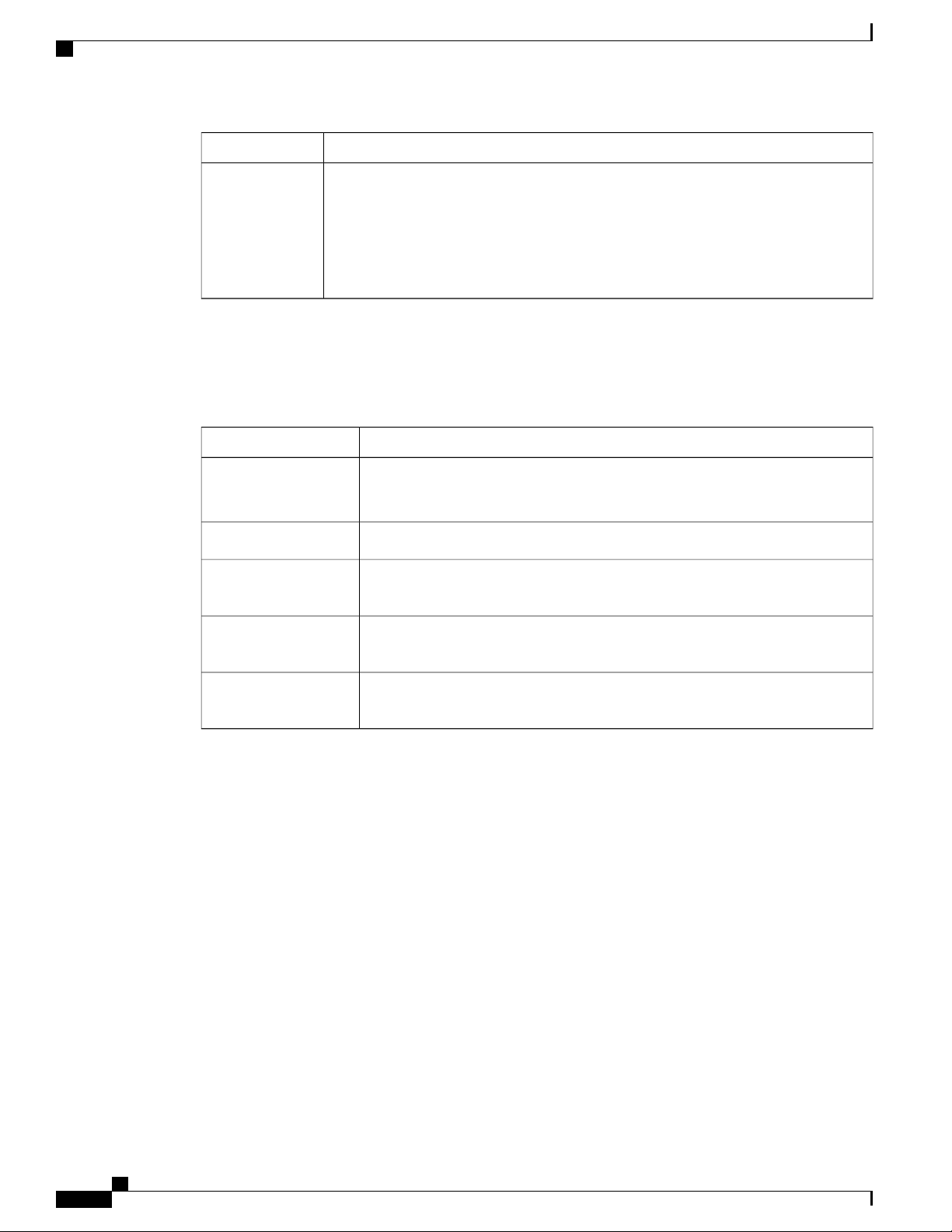
This document uses the following conventions:
DescriptionConvention
^ or Ctrl
Italic font
...
|
[x | y]
Both the ^ symbol and Ctrl represent the Control (Ctrl) key on a keyboard. For
example, the key combination ^D or Ctrl-D means that you hold down the Control
key while you press the D key. (Keys are indicated in capital letters but are not
case sensitive.)
Commands and keywords and user-entered text appear in bold font.bold font
Document titles, new or emphasized terms, and arguments for which you supply
values are in italic font.
Terminal sessions and information the system displays appear in courier font.Courier font
Bold Courier font indicates text that the user must enter.Bold Courier font
Elements in square brackets are optional.[x]
An ellipsis (three consecutive nonbolded periods without spaces) after a syntax
element indicates that the element can be repeated.
A vertical line, called a pipe, indicates a choice within a set of keywords or
arguments.
Optional alternative keywords are grouped in brackets and separated by vertical
bars.
Catalyst 3850 Switch Hardware Installation Guide
OL-26779-05 ix
Page 10
Document Conventions
Preface
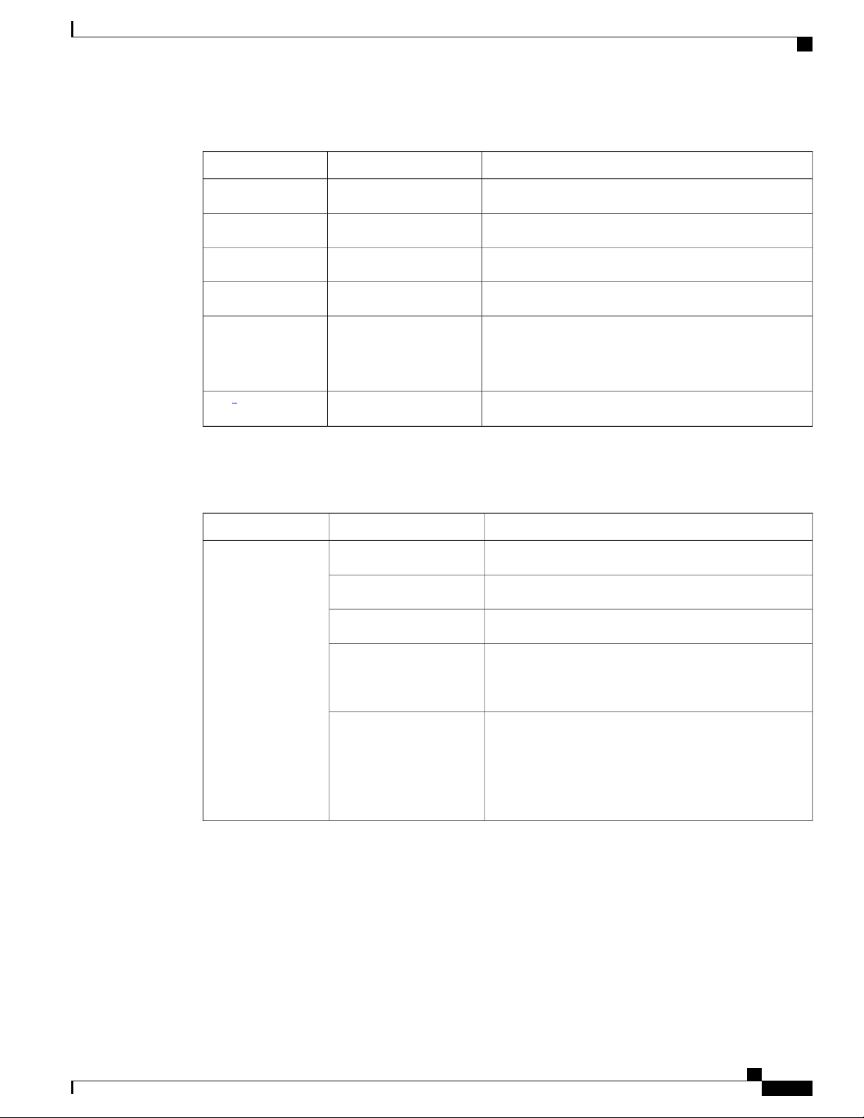
DescriptionConvention
Note
{x | y}
Required alternative keywords are grouped in braces and separated by vertical
bars.
[x {y | z}]
Nested set of square brackets or braces indicate optional or required choices
within optional or required elements. Braces and a vertical bar within square
brackets indicate a required choice within an optional element.
string
A nonquoted set of characters. Do not use quotation marks around the string or
the string will include the quotation marks.
Nonprinting characters such as passwords are in angle brackets.< >
Default responses to system prompts are in square brackets.[ ]
!, #
An exclamation point (!) or a pound sign (#) at the beginning of a line of code
indicates a comment line.
Reader Alert Conventions
This document may use the following conventions for reader alerts:
Means reader take note. Notes contain helpful suggestions or references to material not covered in the
manual.
Tip
Caution
Timesaver
Warning
Means the following information will help you solve a problem.
Means reader be careful. In this situation, you might do something that could result in equipment damage
or loss of data.
Means the described action saves time. You can save time by performing the action described in the
paragraph.
IMPORTANT SAFETY INSTRUCTIONS
This warning symbol means danger. You are in a situation that could cause bodily injury. Before you
work on any equipment, be aware of the hazards involved with electrical circuitry and be familiar with
standard practices for preventing accidents. Use the statement number provided at the end of each warning
to locate its translation in the translated safety warnings that accompanied this device. Statement 1071
SAVE THESE INSTRUCTIONS
Catalyst 3850 Switch Hardware Installation Guide
x OL-26779-05
Page 11

Preface
Related Documentation
Before installing or upgrading the switch, refer to the switch release notes.Note
Cisco Catalyst 3850 Series Switches documentation, located at:
•
http://www.cisco.com/go/cat3850_docs
Cisco Catalyst 3650 Series Switchesdocumentation, located at:
•
http://www.cisco.com/go/cat3650_docs
Catalyst 2960-X Switch documentation, located at:
•
http://www.cisco.com/go/cat2960x_docs
Cisco SFP and SFP+ modules documentation, including compatibility matrixes, located at:
•
http://www.cisco.com/en/US/products/hw/modules/ps5455/tsd_products_support_series_home.html
Related Documentation
Cisco SFP, SFP+, and QSFP+ modules documentation, including compatibility matrixes, located at:
•
http://www.cisco.com/en/US/products/hw/modules/ps5455/tsd_products_support_series_home.html
Cisco Validated Designs documents, located at:
•
http://www.cisco.com/go/designzone
Obtaining Documentation and Submitting a Service Request
For information on obtaining documentation, submitting a service request, and gathering additional information,
see the monthly What's New in Cisco Product Documentation, which also lists all new and revised Cisco
technical documentation, at:
http://www.cisco.com/c/en/us/td/docs/general/whatsnew/whatsnew.html
Subscribe to the What's New in Cisco Product Documentation as a Really Simple Syndication (RSS) feed
and set content to be delivered directly to your desktop using a reader application. The RSS feeds are a free
service and Cisco currently supports RSS version 2.0.
Catalyst 3850 Switch Hardware Installation Guide
OL-26779-05 xi
Page 12

Obtaining Documentation and Submitting a Service Request
Preface
Catalyst 3850 Switch Hardware Installation Guide
xii OL-26779-05
Page 13

CHAPTER 1
Product Overview
The Catalyst 3850 family of switches are Ethernet switches to which you can connect devices such as Cisco
IP Phones, Cisco Wireless Access Points, workstations, and other network devices such as servers, routers,
and other switches.
The Catalyst 3850 switches support stacking through Cisco StackWise-480 technology and power management
through StackPower. The StackWise technology for the Catalyst 3850 switches is called StackWise-480.
Unless otherwise noted, the term switch refers to a standalone switch and to a switch stack.
This chapter contains these topics:
Switch Models, page 1
•
Front Panel, page 5
•
Rear Panel, page 23
•
Management Options, page 32
•
Switch Models
Table 1: Catalyst 3850 Switch Models and Descriptions
Switch Model
OL-26779-05 1
Supported
Software
Image
LAN BaseWS-C3850-24T-L
LAN BaseWS-C3850-48T-L
LAN BaseWS-C3850-24P-L
Description
Stackable 24 10/100/1000 Ethernet ports, 1 network module
slot1, 350 W power supply
Stackable 48 10/100/1000 Ethernet ports, 1 network module
slot, 350 W power supply
Stackable 24 10/100/1000 PoE+2ports, 1 network module
slot, 715 W power supply
Catalyst 3850 Switch Hardware Installation Guide
Page 14

Switch Models
Product Overview
Switch Model
Supported
Software
Image
LAN BaseWS-C3850-48P-L
LAN BaseWS-C3850-48F-L
LAN BaseWS-C3850-24U-L
LAN BaseWS-C3850-48U-L
LAN BaseWS-C3850-12X48U-L
LAN BaseWS-C3850-24XU-L
IP BaseWS-C3850-24T-S
Description
Stackable 48 10/100/1000 PoE+ ports, 1 network module
slot, 715 W power supply
Stackable 48 10/100/1000 PoE+ ports, 1 network module
slot, 1100 W power supply
Stackable 24 10/100/1000 Cisco UPOE3ports, 1 network
module slot, 1100 W power supply
Stackable 48 10/100/1000 Cisco UPOE ports, 1 network
module slot, 1100 W power supply
Stackable 12 100M/1G/2.5G/5G/10G and 36 1G UPoE ports,
1 network module slot, 1100 W power supply
Stackable 24 100M/1G/2.5G/5G/10G UPoE ports, 1 network
module slot, 1100-W power supply
Stackable 24 10/100/1000 Ethernet ports, 1 network module
slot, 350 W power supply
IP BaseWS-C3850-48T-S
Stackable 48 10/100/1000 Ethernet ports, 1 network module
slot, 350 W power supply
IP BaseWS-C3850-24P-S
Stackable 24 10/100/1000 PoE+ ports, 1 network module
slot, 715 W power supply
IP BaseWS-C3850-48P-S
Stackable 48 10/100/1000 PoE+ ports, 1 network module
slot, 715 W power supply
IP BaseWS-C3850-48F-S
Stackable 48 10/100/1000 PoE+ ports, 1 network module
slot, 1100 W power supply
IP BaseWS-C3850-24U-S
Stackable 24 10/100/1000 Cisco UPOE ports, 1 network
module slot, 1100 W power supply
IP BaseWS-C3850-48U-S
Stackable 48 10/100/1000 Cisco UPOE ports, 1 network
module slot, 1100 W power supply
IP BaseWS-C3850-24PW-S
Catalyst 3850 24-port PoE IP Base with 5 access points
license
IP BaseWS-C3850-48PW-S
Catalyst 3850 48-port PoE IP Base with 5 access points
license
IP BaseWS-C3850-12S-S
Stackable 12 SFP module slots, 1 network module slot, 350
W power supply
Catalyst 3850 Switch Hardware Installation Guide
2 OL-26779-05
Page 15

Product Overview
Switch Models
Switch Model
Supported
Software
Image
IP BaseWS-C3850-24S-S
IP BaseWS-C3850-12XS-S
IP BaseWS-C3850-16XS-S
IP BaseWS-C3850-24XS-S
IP BaseWS-C3850-32XS-S
IP BaseWS-C3850-48XS-S
Description
Stackable 24 SFP module slots, 1 network module slot, 350
W power supply
Catalyst 3850 12-port SFP+ transceiver, 1 network module
slot, support for up to 10 G SFP+, 350 W power supply
Catalyst 3850 16-port SFP+ transceiver, 1 network module
slot, support for up to 10 G SFP+, 350 W power supply.
16 ports are available when the C3850-NM-4-10G network
module is plugged into the WS-C3850-12XS-S switch.
Catalyst 3850 24-port SFP+ transceiver, 1 network module
slot, support for up to 10 G SFP+, 715 W power supply.
Catalyst 3850 32-port SFP+ transceiver, 1 network module
slot, support for up to 10 G SFP+, 715 W power supply.
32 ports are available when the C3850-NM-8-10G network
module is plugged into the WS-C3850-24XS-S switch.
Catalyst 3850 switch with SFP+ transceivers, 48 ports that
support up to 10 G, and 4 QSFP ports that support up to 40
G. 750 W power supply.
4
The airflow direction for this switch is from the front panel
to the rear panel.
IP BaseWS-C3850-48XS-F-S
Catalyst 3850 switch with SFP+ transceivers, 48 ports that
support up to 10 G, and 4 QSFP ports that support up to 40
G. 750 W power supply.
The airflow direction for this switch is from the rear panel to
the front panel.
IP BaseWS-C3850-12X48U-S
Stackable 12 100M/1G/2.5G/5G/10G and 36 1 G UPoE ports,
1 network module slot, 1100 W power supply
IP BaseWS-C3850-12X48UW-S
Stackable 12 100M/1G/2.5G/5G/10G and 36 1 G UPoE ports,
1 network module slot, 1100 W power supply
IP BaseWS-C3850-24XU-S
Stackable 24 100M/1G/2.5G/5G/10G UPoE ports, 1 network
module slot, 1100-W power supply
IP BaseWS-C3850-24XUW-S
Stackable 24 100M/1G/2.5G/5G/10G UPoE ports, 1 network
module slot, 1100-W power supply
IP ServicesWS-C3850-24T-E
Stackable 24 10/100/1000 Ethernet ports, 1 network module
slot, 350 W power supply
Catalyst 3850 Switch Hardware Installation Guide
OL-26779-05 3
Page 16

Switch Models
Product Overview
Switch Model
Supported
Software
Image
IP ServicesWS-C3850-48T-E
IP ServicesWS-C3850-24P-E
IP ServicesWS-C3850-48P-E
IP ServicesWS-C3850-48F-E
IP ServicesWS-C3850-24U-E
IP ServicesWS-C3850-48U-E
IP ServicesWS-C3850-12S-E
Description
Stackable 48 10/100/1000 Ethernet ports, 1 network module
slot, 350 W power supply
Stackable 24 10/100/1000 PoE+ ports, 1 network module
slot, 715 W power supply
Stackable 48 10/100/1000 PoE+ ports, 1 network module
slot, 715 W power supply
Stackable 48 10/100/1000 PoE+ ports, 1 network module
slot, 1100 W power supply
Stackable 24 10/100/1000 Cisco UPOE ports, 1 network
module slot, 1100 W power supply
Stackable 48 10/100/1000 Cisco UPOE ports, 1 network
module slot, 1100 W power supply
Stackable 12 SFP module slots, 1 network module slot, 350
W power supply
IP ServicesWS-C3850-24S-E
Stackable 24 SFP module slots, 1 network module slot, 350
W power supply
IP ServicesWS-C3850-12XS-E
Catalyst 3850 12-port SFP+ transceiver, 1 network module
slot, support for up to 10 G SFP+, 350 -W power supply.
IP ServicesWS-C3850-16XS-E
Catalyst 3850 16-port SFP+ transceiver, 1 network module
slot, support for up to 10 G SFP+, 350 W power supply.
16 ports are available when the C3850-NM-4-10G network
module is plugged into the WS-C3850-12XS-E switch.
IP ServicesWS-C3850-24XS-E
Catalyst 3850 24-port SFP+ transceiver, 1 network module
slot, support for up to 10 G SFP+, 715 W power supply.
IP ServicesWS-C3850-32XS-E
Catalyst 3850 32-port SFP+ transceiver, 1 network module
slot, support for up to 10 G SFP+, 715 W power supply.
32 ports are available when the C3850-NM-8-10G network
module is plugged into the WS-C3850-24XS-E switch.
IP ServicesWS-C3850-48XS-E
Catalyst 3850 switch with SFP+ transceivers, 48 ports that
support up to 10 G, and 4 QSFP ports that support up to 40
G. 750 W power supply.
The airflow direction for this switch is from the front panel
to the rear panel.
Catalyst 3850 Switch Hardware Installation Guide
4 OL-26779-05
Page 17

Product Overview
Front Panel
Switch Model
Supported
Software
Image
IP ServicesWS-C3850-48XS-F-E
IP ServicesWS-C3850-12X48U-E
IP ServicesWS-C3850-24XU-E
1
For supported network modules, see Network Modules, on page 10 .
2
PoE+ = Power over Ethernet plus (provides up to 30 W per port).
3
UPOE = Universal Power Over Ethernet (provides up to 60 W Cisco UPOE per port)
4
The WS-C3850-48XS switches do not support StackWise-480
Front Panel
Description
Catalyst 3850 switch with SFP+ transceivers, 48 ports that
support up to 10 G, and 4 QSFP ports that support up to 40
G. 750 W power supply.
The airflow direction for this switch is from the rear panel to
the front panel.
Stackable 12 100M/1G/2.5G/5G/10G and 36 1 G UPoE ports,
1 network module slot, 1100 W power supply
Stackable 24 100M/1G/2.5G/5G/10G UPoE ports, 1 network
module slot, 1100-W power supply
This section describes the front panel components:
24 or 48 downlink ports of one of these types:
•
10/100/1000
◦
10/100/1000 PoE+
◦
10/100/1000 Cisco UPoE
◦
10 G SFP+
◦
12 or 24 SFP or SFP+ module downlink slots
•
Uplink network modules slot
•
USB Type A connector
•
USB mini-Type B (console) port
•
LEDs
•
Mode button
•
All of the switches have similar components. See the following illustrations for examples.
Catalyst 3850 Switch Hardware Installation Guide
OL-26779-05 5
Page 18
Front Panel
Product Overview
The Catalyst 3850 switches might have slight cosmetic differences on the bezels.Note
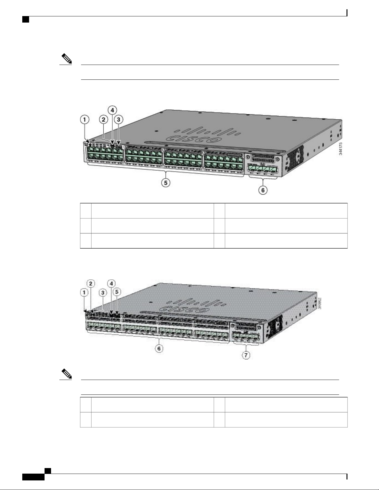
Figure 1: WS-C3850-48P-L Switch Front Panel
Figure 2: WS-C3850-24S Switch Front Panel
The WS-C3850-12S switches have similar front panels.Note
USB mini-Type B (console) port4Mode button1
10/100/1000 PoE+ ports5Status LEDs2
Network module6USB Type A storage port3
USB Type A storage port5UID button1
SFP module slots (downlink)6Mode button2
Catalyst 3850 Switch Hardware Installation Guide
6 OL-26779-05
Page 19
Product Overview
10/100/1000 Ports
Network module7Status LEDs3
USB mini-Type B (console) port4
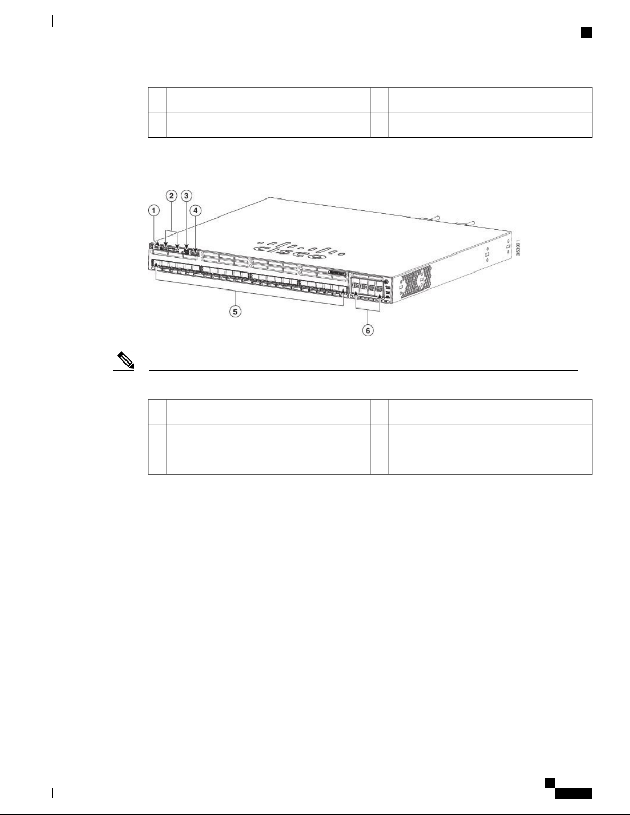
Figure 3: WS-C3850-24XS-E Switch Front Panel
The WS-C3850-24XS-E switches have the following components.Note
10/100/1000 Ports
The 10/100/1000 ports use RJ-45 connectors with Ethernet pinouts. The maximum cable length is 328 feet
(100 meters). The 10BASE-T, 100BASE-TX, 1000BASE-T traffic requires Category 5 or Category 5e twisted
pair (UTP) cable. The 10BASE-T traffic can use Category 3 or Category 4 UTP cable.
PoE, PoE+, and Cisco UPoE Ports
The PoE+ and Cisco Universal Power Over Ethernet (Cisco UPoE) ports use the same connectors as described
in 10/100/1000 Port Connections, on page 50. They provide:
PoE+ ports: Support for IEEE 802.3af-compliant powered devices (up to 15.4 W PoE per port) and
•
support for IEEE 802.3at-compliant powered devices (up to 30 W PoE+ per port). The maximum total
PoE power in a 1RU switch is 1800 W.
USB mini-Type B (console) port4Mode button1
10 G SFP+ ports5Status LEDs2
Network module6USB Type A storage port3
Support for Cisco-enhanced PoE.
•
Catalyst 3850 Switch Hardware Installation Guide
OL-26779-05 7
Page 20

SFP and QSFP Module Slots
•
•
•
Depending on the installed power supply modules, each port can deliver up to 60 W of Cisco UPOE. See the
Power Supply Modules, on page 26 for the power supply matrix that defines the available PoE, PoE+, and
Cisco UPOE power per port. The output of the PoE+ circuit has been evaluated as a Limited Power Source
(LPS) per IEC 60950-1.
Product Overview
Support for prestandard Cisco powered devices.
Configuration for StackPower. When the switch internal power supply module(s) cannot support the
total load, StackPower configurations allow the switch to leverage power available from other switches.
Configurable support for Cisco intelligent power management, including enhanced power negotiation,
power reservation, and per-port power policing.
Note
Restrictions for the WS-C3850-12X48U-L, WS-C3850-12X48U-S and WS-C3850-12X48U-E switch
models:
A maximum of 28 ports are available for UPoE connections. This is because some power from the
•
power supplies is diverted to the switch, and only the remaining power is transmitted to the ports.
SFP and QSFP Module Slots
The uplink and downlink ports for the Catalyst WS-C3850 switch models are as follows.
The downlink ports on the Catalyst WS-C3850-12S and WS-C3850-24S switch models support standard
•
SFP modules.
The downlink ports on the Catalyst WS-C3850-12XS and WS-C3850-24XS switch models support
•
standard SFP+ modules.
The 10G downlink ports on the Catalyst WS-C3850-48XS-S, WS-C3850-48XS-F-S, WS-C3850-48XS-E
•
and WS-C3850-48XS-F-E switch models support standard SFP+ modules.
The 40G downlink ports on the Catalyst WS-C3850-48XS-S, WS-C3850-48XS-F-S, WS-C3850-48XS-E
•
and WS-C3850-48XS-F-E switch models support standard QSFP modules.
For supported SFP modules, refer to the Cisco Transceiver Modules Compatibility Information at http://
www.cisco.com/en/US/products/hw/modules/ps5455/products_device_support_tables_list.html
Note
For information about the (uplink) SFP module slots on the network modules, see Network Modules, on
page 10.
Management Ports
The management ports connect the switch to a PC running Microsoft Windows or to a terminal server.
Ethernet management port. See Ethernet Management Port, on page 31.
•
RJ-45 console port (EIA/TIA-232). See RJ-45 Console Port, on page 32.
•
Catalyst 3850 Switch Hardware Installation Guide
8 OL-26779-05
Page 21
Product Overview
USB Type A Port
USB mini-Type B console port (5-pin connector).
•
The 10/100/1000 Ethernet management port connection uses a standard RJ-45 crossover or straight-through
cable. The RJ-45 console port connection uses the supplied RJ-45-to-DB-9 female cable. The USB console
port connection uses a USB Type A to 5-pin mini-Type B cable. The USB console interface speeds are the
same as the RJ-45 console interface speeds.
If you use the USB mini-Type B console port, the Cisco Windows USB device driver must be installed on
any PC connected to the console port (for operation with Microsoft Windows). Mac OS X or Linux do not
require special drivers.
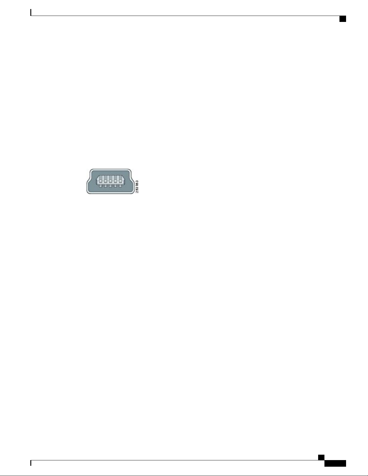
The 4-pin mini-Type B connector resembles the 5-pin mini-Type B connectors. They are not compatible. Use
only the 5-pin mini-Type B.
This illustration shows a 5-pin mini-Type B USB port.
Figure 4: USB Mini-Type B Port
With the Cisco Windows USB device driver, you can connect and disconnect the USB cable from the console
port without affecting Windows HyperTerminal operations.
The console output always goes to both the RJ-45 and the USB console connectors, but the console input is
active on only one of the console connectors at any one time. The USB console takes precedence over the
RJ-45 console. When a cable is connected into the USB console port, the RJ-45 console port becomes inactive.
Conversely, when the USB cable is disconnected from the USB console port, the RJ-45 port becomes active.
You can use the command-line interface (CLI) to configure an inactivity timeout which reactivates the RJ-45
console if the USB console has been activated and no input activity has occurred on the USB console for a
specified time.
After the USB console deactivates due to inactivity, you cannot use the CLI to reactivate it. Disconnect and
reconnect the USB cable to reactivate the USB console. For information on using the CLI to configure the
USB console interface, see the software guide.
USB Type A Port
The USB Type A port provides access to external USB flash devices (also known as thumb drives or USB
keys) and to specific Cisco USB Bluetooth devices.
The port supports Cisco USB flash drives with capacities from 128 MB to 8 GB (USB devices with port
densities of 128 MB, 256 MB, 1 GB, 4 GB, and 8 GB are supported). When combined with stacking, you can
upgrade other switches in the stack from an USB key inserted in any switch within the stack. Cisco IOS
software provides standard file system access to the flash device: read, write, erase, and copy, as well as the
ability to format the flash device with a FAT file system.
It provides you with the ability to automatically upgrade the internal flash with the USB drive's configuration
and image for emergency switch recovery using USB auto-upgrade. This feature checks the internal flash for
a bootable image and configuration and if either image or the configuration is not available, then the USB
drive is checked for boot images and configuration. If the boot image and configuration are available, these
are copied to flash for the reboot.
Catalyst 3850 Switch Hardware Installation Guide
OL-26779-05 9
Page 22
Network Modules
Product Overview
The port supports Cisco USB Bluetooth devices. The USB Bluetooth device acts as a Bluetooth host and
serves as either a serial port or a management port connection. You can pair it with your Bluetooth smart
phone, laptop, or tablet. If you configure the serial profile on the Bluetooth device, the switch turns the USB
port into a serial port. If you configure the Personal Area Network (PAN) profile on the Bluetooth device, the
switch turns the USB port into a management interface.
Figure 5: Cisco USB Bluetooth
Network Modules
The switch supports one hot-swappable network module that provides uplink ports to connect to other devices.
The switch should only be operated with either a network module or a blank module installed.
The switch generates logs when you insert or remove a network module with SFP ports.
Table 2: Network Modules
C3850-NM-4-1G
5
DescriptionNetwork Module
This module has four 1 G SFP module slots. Any combination of standard SFP
modules are supported. SFP+ modules are not supported.
If you insert an SFP+ module in the 1 G network module, the SFP+ module does
not operate, and the switch logs an error message.
Note
This is supported on the following switch
models:
WS-C3850-24T/P/U
•
WS-C3850-48T/F/P/U
•
WS-C3850-12X48U
•
WS-C3850-24XU
•
WS-C3850-12S
•
WS-C3850-24S
•
Catalyst 3850 Switch Hardware Installation Guide
10 OL-26779-05
Page 23

Product Overview
Network Modules
C3850-NM-2-10G
C3850-NM-4-10G
5
DescriptionNetwork Module
This module has four slots:
Two slots (left side) support only 1 G SFP modules and two slots (right side)
support either 1 G SFP or 10 G SFP modules.
Note
This is supported on the following switch
models:
WS-C3850-24T/P/U
•
WS-C3850-48T/F/P/U
•
WS-C3850-12X48U
•
WS-C3850-24XU
•
WS-C3850-12S
•
WS-C3850-24S
•
This module has four 10 G slots or four 1 G slots.
Note
This is supported on the following switch
models:
WS-C3850-48T/F/P/U
•
WS-C3850-12X48U
•
C3850-NM-8-10G
C3850-NM-2-40G
WS-C3850-24XU
•
WS-C3850-12XS
•
WS-C3850-24XS
•
This module has eight 10 G slots with an SFP+ port in each slot. Each port
supports a 1 G or 10 G connection
Note
This is supported on the following switch
models:
WS-C3850-12X48U
•
WS-C3850-24XU
•
WS-C3850-24XS
•
This module has two 40 G slots with a QSFP+ connector in each slot.
Note
This is supported on the following switch
models:
WS-C3850-12X48U
•
WS-C3850-24XU
•
WS-C3850-24XS
•
Catalyst 3850 Switch Hardware Installation Guide
OL-26779-05 11
Page 24

LEDs
Product Overview
C3850-NM-BLANK
5
All network modules are hot-swappable.
For information about the network modules, see the Installing Network Modules, on page 59. For cable
specifications, see Cables and Adapters, on page 103.
SFP and SFP+ Modules
The SFP and SFP+ modules provide copper or fiber-optic connections to other devices. These transceiver
modules are field-replaceable, and they provide the uplink interfaces (expect in the fixed SFP slots in the
WS-C3850-12S and WS-C3850-24S switches) when installed in an SFP module slot. The SFP modules have
LC connectors for fiber-optic connections or RJ-45 connectors for copper connections.
Note
The downlink ports on the Catalyst WS-C3850-12S and WS-C3850-24S switch models support standard
SFP modules, and the downlink ports on the Catalyst WS-C3850-12XS and WS-C3850-24XS switch
models support standard SFP+ modules.
Use only Cisco SFP and SFP+ modules on the switch. For the latest information about supported SFP and
SFP+ modules, refer to the Cisco Transceiver Modules Compatibility Information at http://www.cisco.com/
en/US/products/hw/modules/ps5455/products_device_support_tables_list.html
For information about SFP modules, see the documentation at Installing SFP and SFP+ Modules, on page
65.
5
DescriptionNetwork Module
Insert this blank module when the switch has no uplink ports (this is required
for sufficient air flow).
LEDs
The Catalyst 3850 switch supports the SFP module patch cable (CAB-SFP-50CM), a 0.5-meter, copper,
passive cable with SFP module connectors at each end. This cable is only used with 1-Gigabit Ethernet SFP
ports to connect two Catalyst 3850 switches in a cascaded configuration.
For information about QSFP modules, see the documentation at
QSFP Port Cabling Specifications
•
Cisco S-Class 40GBASE QSFP Modules Data Sheet
•
You can use the switch LEDs to monitor switch activity and its performance.
Catalyst 3850 switches might have slight cosmetic differences on the bezels.Note
Catalyst 3850 Switch Hardware Installation Guide
12 OL-26779-05
Page 25
Product Overview
LEDs
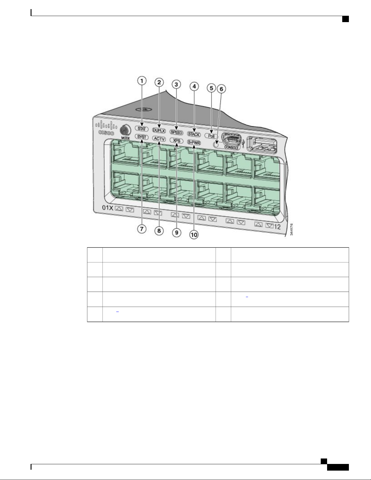
This figure shows the switch LEDs and the Mode button that you use to select a port mode.
Figure 6: Switch Front Panel LEDs
5
6
XPS = expandable power system.
USB mini-Type B console port LED6STAT (status)1
SYST (system)7DUPLX (duplex)2
ACTV (active)8SPEED3
6
XPS
9STACK4
7
S-PWR (StackPower)10PoE
Catalyst 3850 Switch Hardware Installation Guide
OL-26779-05 13
Page 26
LEDs
7
Only on switch models that support PoE.
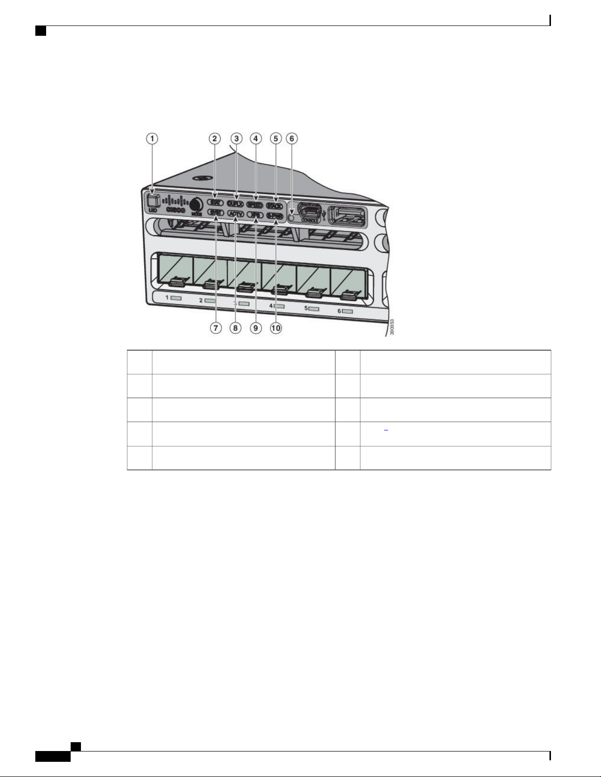
Figure 7: Switch Front Panel LEDs for the WS-C3850-12S, WS-C3850-24S, WS-C3850-12XS, and WS-C3850-24XS Switches
Product Overview
USB mini-Type B console port LED6UID (blue beacon)1
SYST (system)7STAT (status)2
ACTV (active)8DUPLX (duplex)3
8
XPS
9SPEED4
S-PWR (StackPower)10STACK5
Catalyst 3850 Switch Hardware Installation Guide
14 OL-26779-05
Page 27
Product Overview
8
XPS = expandable power system.
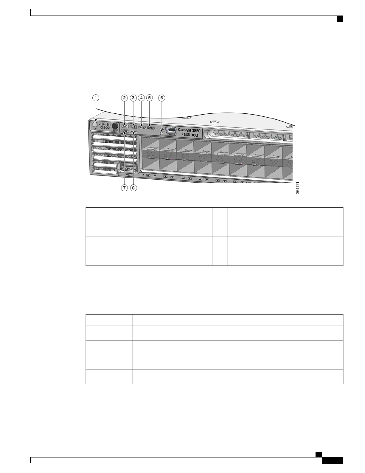
Figure 8: Switch Front Panel LEDs for the WS-C3850-48XS Switches
LEDs
SYST LED
STACK5UID (blue beacon)1
USB mini-Type B console port LED6STAT (status)2
SYST (system)7DUPLX (duplex)3
ACTV (active)8SPEED4
Table 3: SYST LED
System StatusColor
System is not powered on.Off
System is operating normally.Green
POST in progress.Blinking green
System is receiving power but is not functioning properly.Amber
Catalyst 3850 Switch Hardware Installation Guide
OL-26779-05 15
Page 28
LEDs
Product Overview
System StatusColor
XPS LED
Blinking amber
Table 4: XPS LED
Off
Blinking green
There is a fault with one of the following:
Network module (non traffic-related)
•
Power supply
•
Fan module
•
DescriptionColor
XPS cable is not installed.
Switch is in StackPower mode.
XPS is connected and ready to provide back-up power.Green
XPS is connected but is unavailable because it is providing power to another device
(redundancy has been allocated to a neighboring device).
Amber
Blinking amber
For information about the XPS 2200, see the Cisco eXpandable Power System 2200 Hardware Installation
Guide on Cisco.com:
http://www.cisco.com/go/xps2200_hw
Port LEDs and Modes
Each Ethernet port, 1-Gigabit Ethernet module slot, and 10-Gigabit Ethernet module slot has a port LED.
These port LEDs, as a group or individually, display information about the switch and about the individual
ports. The port mode determines the type of information shown by the port LEDs.
To select or change a mode, press the Mode button until the desired mode is highlighted. When you change
port modes, the meanings of the port LED colors also change.
When you press the Mode button on any switch in the switch stack, all the stack switches change to show the
same selected mode. For example, if you press the Mode button on the active switch to show the SPEED
LED, all the other switches in the stack also show the SPEED LED.
The XPS is in standby mode or in a fault condition. See the XPS 2200
documentation for information about the standby mode and fault conditions.
The power supply in a switch has failed, and the XPS is providing power to that
switch (redundancy has been allocated to this device).
Catalyst 3850 Switch Hardware Installation Guide
16 OL-26779-05
Page 29
Product Overview
LEDs
Table 5: Port Mode LEDs
DescriptionPort ModeMode LED
The port status. This is the default mode.Port statusSTAT
The port operating speed: 10, 100, or 1000 Mb/s.Port speedSPEED
The port duplex mode: full duplex or half duplex.Port duplex modeDUPLX
The active switch status.ActiveACTV
9
Only switches with PoE+ ports.
Table 6: Meaning of Switch LED Colors in Different Modes
STACK
9
Stack member status
StackWise port status
Alternating green-amber
Amber
Stack member status.
The StackWise port status. See STACK LED, on page
20.
The PoE+ port status.The PoE+ port status.PoE
MeaningPort LED ColorPort Mode
No link, or port was administratively shut down.OffSTAT (port status)
Link present, no activity.Green
Activity. Port is sending or receiving data.Blinking green
Link fault. Error frames can affect connectivity, and errors
such as excessive collisions, CRC errors, and alignment
and jabber errors are monitored for a link-fault indication.
Port is blocked by Spanning Tree Protocol (STP) and is
not forwarding data.
After a port is reconfigured, the port LED can be amber
for up to 30 seconds as STP checks the switch for possible
loops.
Catalyst 3850 Switch Hardware Installation Guide
OL-26779-05 17
Page 30

LEDs
Product Overview
MeaningPort LED ColorPort Mode
10/100/1000/SFP portsSPEED
Port is operating at 10 Mb/s.Off
Port is operating at 100 Mb/s.Green
Port is operating at 1000 Mb/s.Single green flash (on for
100 ms, off for 1900 ms)
Port is operating at 2500, 5000 or 10000 Mb/sBlinking twice
Network module slots
Port is not operating.Off
Port is operating at up to 10 Gb/s.Blinking green
switch)
member)
OffACTV (data active
Blinking green
Port is operating in half duplex.OffDUPLX (duplex)
Port is operating in full duplex.Green
The switch is not the active switch.
Note
For a standalone switch, this LED is
off.
The switch is the active switch.Green
Error during active switch election.Amber
Switch is a standby member of a data stack and assumes
active responsibilities if the current active switch fails.
No stack member corresponding to that member number.OffSTACK (stack
Stack member number.Blinking green
Member numbers of other stack member switches.Green
Catalyst 3850 Switch Hardware Installation Guide
18 OL-26779-05
Page 31

Product Overview
LEDs
MeaningPort LED ColorPort Mode
10
OffPoE+
PoE+ is off.
If the powered device is receiving power from an AC
power source, the port LED is off even if the device is
connected to the switch port.
10
Only switches with PoE or PoE+ ports.
Green
Alternating green-amber
Blinking amber
Amber
PoE+ is on. The port LED is green when the switch port
is providing power.
PoE+ is denied because providing power to the powered
device will exceed the switch power capacity.
PoE+ is off due to a fault or because it has exceeded a
limit set in the switch software.
Caution
PoE+ faults occur when noncompliant cabling
or powered devices are connected to a PoE+
port. Use only standard-compliant cabling to
connect Cisco prestandard IP Phones and
wireless access points or IEEE
802.3af-compliant devices to PoE+ ports. You
must remove from the network any cable or
device that causes a PoE+ fault.
PoE+ for the port has been disabled.
Note
PoE+ is enabled by
default.
USB Console LED
The USB console LED shows whether there is an active USB connection to the port.
Table 7: USB Console LED
DescriptionColorLED
USB console port is active.GreenUSB console port
The USB is disabled.Off
Catalyst 3850 Switch Hardware Installation Guide
OL-26779-05 19
Page 32

LEDs
S-PWR LED
Product Overview
Table 8: S-PWR LED
DescriptionColor
StackPower cable is not connected, or the switch is in standalone mode.Off
Each StackPower port is connected to another switch.Green
ACTV LED
Blinking green
Amber
Table 9: ACTV LED
Amber
This appears on the switch in a StackPower ring configuration that detects an open
ring or has only one StackPower cable connected.
There is a fault: load shedding is occurring, a StackPower cable is defective, or
an administrative action is required. See the switch software configuration guide
for information about configuring StackPower.
The StackPower budget is not sufficient to meet current power demands.Blinking amber
DescriptionColor
Switch is not the active switch.Off
Switch is the active switch or a standalone switch.Green
Switch is in stack standby mode.Slow blinking green
An error occurred when the switch was selecting the active switch, or another type
of stack error occurred.
STACK LED
The STACK LED shows the sequence of member switches in a stack. Up to eight switches can be members
of a stack. The first eight port LEDs show the member number of a switch in a stack.
This figure shows the LEDs on the first switch, which is stack member number 1. For example, if you press
the Mode button and select Stack, the LED for port 1 blinks green. The LEDs for ports 2 and 3 are solid green,
Catalyst 3850 Switch Hardware Installation Guide
20 OL-26779-05
Page 33

Product Overview
LEDs
as these represent the member numbers of other switches in the stack. The other port LEDs are off because
there are no more members in the stack.
Figure 9: STACK LED
LED blinks green to show that this is switch 1
4Stack member 11
in the stack.
PoE LED
LED is solid green to show that switch 2 is a
5Stack member 22
stack member.
LED is solid green to show that switch 3 is a
6Stack member 33
stack member.
The PoE LED indicates the status of the PoE mode: either PoE, PoE+, or Cisco UPOE.
Table 10: PoE LED
DescriptionColor
Off
PoE mode is not selected. None of the 10/100/1000 ports have been denied power
or are in a fault condition.
PoE mode is selected, and the port LEDs show the PoE mode status.Green
Blinking amber
PoE mode is not selected. At least one of the 10/100/1000 ports has been denied
power, or at least one of the 10/100/1000 ports has a PoE mode fault.
UID/Beacon LED
The UID and the Beacon LED can be turned on by the administrator to indicate that the switch needs attention.
It helps the administrator identify the switch. The beacon can be turned on by either pressing the UID button
Catalyst 3850 Switch Hardware Installation Guide
OL-26779-05 21
Page 34

LEDs
Product Overview
on the switch front panel, or by using the CLI. There is a blue beacon on the front and rear panel of the switch.
The blue beacon on the front panel is a button labeled UID, and on the back panel it is a LED labeled BEACON.
Table 11: UID/Beacon LED Indicator (Applies Only to the WS-C3850-12S, WS-C3850-24S , WS-C3850-12XS, and
WS-C3850-24XS Switches)
DescriptionColor/State
Solid blue
Network Module LEDs
Figure 10: Network Module LEDs
Blinking green
The operator has indicated that the system needs
attention.
G3 LED3G1 LED1
G4 LED4G2 LED2
Network Module Link StatusColor
Link is off.Off
Link is on; no activity.Green
Activity on a link; no faults.
The LED will blink green even when there is very little control traffic.Note
Blinking amber
Link is off due to a fault or because it has exceeded a limit set in the switch software.
Caution
Link faults occur when noncompliant cabling is connected to an SFP or SFP+
port. Use only standard-compliant cabling to connect to Cisco SFP and SFP+
ports. You must remove from the network any cable or device that causes a
link fault.
Link for the SFP or SFP+ has been disabled.Amber
Catalyst 3850 Switch Hardware Installation Guide
22 OL-26779-05
Page 35

Product Overview
Rear Panel
Rear Panel
The switch rear panel includes StackWise connectors, StackPower or XPS 2200 connectors, ports, fan modules,
and power supply modules.
Figure 11: Catalyst 3850 Switch Rear Panel
StackWise port connector6Ground connector1
StackPower connector7CONSOLE (RJ-45 console port)2
3
port)
AC OK (input) status LED8MGMT (RJ-45 10/100/1000 management
PS OK (output) status LED9RESET button4
Power supply modules (AC power supply
10Fan module5
modules shown)
Catalyst 3850 Switch Hardware Installation Guide
OL-26779-05 23
Page 36

Rear Panel
Product Overview
Figure 12: WS-C3850-12S and WS-C3850-24S Switches Switch Rear Panel
StackWise port connector7Ground connector1
StackPower connector8CONSOLE (RJ-45 console port)2
3
AC OK (input) status LED9MGMT (RJ-45 10/100/1000 management
port)
PS OK (output) status LED10RESET button4
Power supply modules (AC power supply
11BEACON LED5
modules shown)
Fan module6
Catalyst 3850 Switch Hardware Installation Guide
24 OL-26779-05
Page 37

Product Overview
Rear Panel
Figure 13: WS-C3850-48XS Switches Switch Rear Panel
Fan module5Ground connector1
Power supply FAIL LED6CONSOLE (RJ-45 console port)2
Power supply OK LED7BEACON LED3
4
Power supply modules8MGMT (RJ-45 10/100/1000 management 9
AC OK (input) status LED port)
Catalyst 3850 Switch Hardware Installation Guide
OL-26779-05 25
Page 38

RJ-45 Console Port LED
RJ-45 Console Port LED
Table 12: RJ-45 Console Port LED
StackWise Ports
StackWise ports are used to connect switches in StackWise stacking configurations. The switch ships with a
0.5-meter StackWise cable that you can use to connect the StackWise ports. For more information on StackWise
cables, see Connecting to the StackWise Ports, on page 48.
Product Overview
RJ-45 Console Port StatusColor
RJ-45 console is disabled. USB console is active.Off
RJ-45 console is enabled. USB console is disabled.Green
Caution
Use only approved cables, and connect only to similar Cisco equipment. Equipment might be damaged
if connected to nonapproved Cisco cables or equipment.
Power Supply Modules
The switches are powered through one or two internal power supply modules.
Supported power supply modules:
PWR-C1-350WAC
•
PWR-C1-715WAC
•
PWR-C1-1100WAC
•
PWR-C1-440WDC
•
The following power supply modules are applicable to only the WS-C3850-48XS switches:
PWR-C3-750WAC-R: This module has red handles to match fans with red handles. Airflow is from the
•
front panel to the rear panel (warm air is ‘pulled out of’ the switch.)
PWR-C3-750WAC-F: This module has blue handles to match fans with blue handles. Airflow is from
•
the rear panel to the front panel (cool air is ‘pushed into’ the switch.)
PWR-C3-750WDC-R: This module has red handles to match fans with red handles. Airflow is from the
•
front panel to the rear panel (warm air is ‘pulled out of’ the switch.)
PWR-C3-750WDC-F: This module has blue handles to match fans with blue handles. Airflow is from
•
the rear panel to the front panel (cool air is ‘pushed into’ the switch.)
Catalyst 3850 Switch Hardware Installation Guide
26 OL-26779-05
Page 39

Product Overview
Power Supply Modules
The switch has two internal power supply module slots. You can use two AC modules, two DC modules, a
mixed configuration of one AC and one DC power supply module, or one power supply module and a blank
module.
The switch can operate with either one or two active power supply modules or with power supplied by a stack.
A Catalyst 3850 switch that is in a StackPower stack can operate with power supplied by other switches in
the stack.
Switch Models, on page 1 shows the default power supply modules that ship with each switch model. All
power supply modules (except the blank modules) have internal fans. All switches ship with a blank power
supply module in the second power supply slot.
Caution
Do not operate the switch with one power supply module slot empty. For proper chassis cooling, both
power supply module slots must be populated with either a power supply or a blank module.
The 350-W and 715-W AC power supply modules are autoranging units that support input voltages between
100 and 240 VAC. The 1100-W power supply module is an autoranging unit that supports input voltages
between 115 and 240 VAC. The 440-W DC power supply module has dual input feeds (A and B) and supports
input voltages between 36 and 72 VDC. The output voltage range is 51 to 57 V.
Each AC power supply module has a power cord for connection to an AC power outlet. The 1100-W and
715-W modules use a 16-AWG cord (only North America). All other modules use an 18-AWG cord. The
DC-power supply module must be wired to a DC-power source.
The following tables show the PoE available and PoE requirements for Catalyst 3850 PoE switch models.
Table 13: Available PoE with AC Power Supply
Available PoEDefault Power SupplyModels
PWR-C1-350WAC12-port data switch
—
24-port data switch
48-port data switch
435 WPWR-C1-715WAC24-port PoE+ switch
48-port PoE+ switch
800 WPWR-C1-1100WAC48-port full PoE+ switch
24-port Cisco UPOE switch
48-port Cisco UPOE switch
Catalyst 3850 Switch Hardware Installation Guide
OL-26779-05 27
Page 40

Power Supply Modules
Table 14: Available PoE with DC Power Supply
Product Overview
Available PoENumber of Power SuppliesModels
220 W124-port PoE+ switch
660 W2
185 W148-port PoE+ switch
625 W2
220 W124-port Cisco UPOE switch
660 W2
185 W148-port Cisco UPOE switch
625 W2
Table 15: Switch Power Supply Requirements for PoE, PoE+, and Cisco UPoE
24-Port SwitchPoE Option
(1) 715 WPoE (up to 15.4 per port)
PoE+ (up to 30 W per ports)
These are the combinations of
power supplies:
(1) 1100 W
•
(1) 715 W + (1) 715 W
•
(2) 1100 WCisco UPoE (up to 60 W per port)
48-Port Switch
11
These are the combinations of
power supplies:
(1) 1100 W
•
(1) 715 W + (1) 715 W
•
These are the combinations of
power supplies:
(1) 1100 W + (1) 715 W
•
(2) 1100 W
•
These are the combinations of
power supplies:
(1) 1100 W + (1) 715 W
•
(2) 1100 W
•
Note
Up to 30 PoE ports can
receive full Cisco UPoE.
11
A 48-port switch with one 715-W power supply provides up to 8.7 W of PoE to all ports.
Catalyst 3850 Switch Hardware Installation Guide
28 OL-26779-05
Page 41

Product Overview
Fan Module
Note
Considerations for the WS-C3850-12X48U-L, WS-C3850-12X48U-S and WS-C3850-12X48U-E switch
models:
The primary power supply for these switch models should be a minimum of 470 W.
•
350 W or 440 W can be used only as secondary power supplies. If the switch draws power from
•
these modules as the primary source, reboot the switch to restore these modules as secondary power
supplies.
The power supply modules have two status LEDs.
Table 16: Switch Power Supply Module LEDs
DescriptionPS OKDescriptionAC OK
DC OK
Off
OffNo AC input power.
No DC input power.
Output is disabled, or input is outside
operating range (AC LED is off).
Output is disabled, or input is outside
operating range (DC LED is off).
Green
DC input power present.
Power output to switch active.GreenAC input power present.
Output has failed.Red
Fan Module
Note
For information about replacing a power supply module, wiring a DC power supply module, and module
specifications, see the "Power Supply Installation" and "Technical Specifications" chapters.
Depending on the switch model, three or five internal hot-swappable 12-V fan modules (FAN-T1=) are
available. The air circulation system consists of the fan modules and the power supply modules. The airflow
patterns vary depending on the power supply configuration.
When the fan modules are operating properly, a green LED is on at the top left corner of the fan assembly
(viewed from the rear). If the fan fails, the LED turns to amber. The switch can operate with two operational
fans, but the failed fan should be replaced as soon as possible to avoid a service interruption due to a second
fan fault.
The WS-C3850 switches require three fans for proper cooling. The WS-C3850-48XS switches require
five fans for proper cooling.
Catalyst 3850 Switch Hardware Installation Guide
OL-26779-05 29
Page 42

Fan Module
Product Overview
The following illustrations show the airflow patterns for the 24- and 48-port switches. The blue arrow shows
cool airflow, and the red arrow shows warm airflow.
Figure 14: 24- and 48-Port Switch Airflow Patterns
Figure 15: Airflow Patterns for the Catalyst 3850-24S-E and 3850-12S-E Switches
Figure 16: Airflow Patterns for the Catalyst 3850-48XS Switches (using Power Supplies and Fans with Blue Handles)
Figure 17: Airflow Patterns for the Catalyst 3850-48XS Switches (using Power Supplies and Fans with Red Handles)
Catalyst 3850 Switch Hardware Installation Guide
30 OL-26779-05
Page 43

Product Overview
For information about installing a fan module and fan specifications, see the "Technical Specifications"
chapter.
StackPower Connector
StackPower Connector
The switches have a StackPower connector for use with Cisco StackPower cables to configure a switch power
stack that includes up to nine switches. A switch power stack can be configured in redundant or power-sharing
mode.
You can order these StackPower cables from your Cisco sales representative:
CAB-SPWR-30CM (0.3-meter cable)
•
CAB-SPWR-150CM (1.5-meter cable)
•
For details about connecting StackPower cables and StackPower guidelines, see Planning a StackPower Stack,
on page 41.
Ethernet Management Port
You can connect the switch to a host such as a Windows workstation or a terminal server through the
10/100/1000 Ethernet management port or one of the console ports. The 10/100/1000 Ethernet management
port is a VPN routing/forwarding (VRF) interface and uses a RJ-45 crossover or straight-through cable.
Note
The 10/100/1000 Ethernet management port is an RJ-45 connector that should be connected to a Windows
workstation or a terminal server. Do not connect this port to another port in the same switch or to any port
within the same switch stack.
The following table shows the Ethernet management port LED colors and their meanings.
Table 17: Ethernet Management Port LED
DescriptionColor
Link up but no activity.Green
Catalyst 3850 Switch Hardware Installation Guide
OL-26779-05 31
Page 44

RJ-45 Console Port
RJ-45 Console Port
The RJ-45 console port connection uses the supplied RJ-45-to-DB-9 female cable.
The following table shows the RJ-45 console port LED colors and their meanings.
Table 18: RJ-45 Console LED
Product Overview
DescriptionColor
Link up and activity.Blinking green
Link down.Off
DescriptionColor
RJ-45 console port is active.Green
Management Options
Cisco Network Assistant
•
Cisco Network Assistant is a PC-based network management GUI application for LANs. You can use
the GUI to configure and manage switch clusters or standalone switches. Cisco Network Assistant is
available at no cost and can be downloaded from this URL: http://www.cisco.com/pcgi-bin/tablebuild.pl/
NetworkAssistant
Cisco IOS CLI
•
You can configure and monitor the switch and switch cluster members from the CLI. You can access
the CLI by connecting your management station directly to the switch console port or by using Telnet
from a remote management station. See the switch command reference on Cisco.com for more information.
Cisco Prime Infrastructure
•
Cisco Prime Infrastructure combines the wireless functionality of Cisco Prime Network Control System
(NCS) and the wired functionality of Cisco Prime LAN Management Solution (LMS), with application
performance monitoring and troubleshooting capabilities of Cisco Prime Assurance Manager. For more
information, see the Cisco Prime Infrastructure documentation on Cisco.com: http://www.cisco.com/en/
US/products/ps12239/index.html
The port is not active.Off
Catalyst 3850 Switch Hardware Installation Guide
32 OL-26779-05
Page 45

CHAPTER 2
Switch Installation
For initial switch setup, assigning the switch IP address, and powering on information, see the switch getting
started guide on Cisco.com.
This chapter contains these topics:
Preparing for Installation, page 33
•
Planning a Switch Data Stack, page 36
•
Data Stack Cabling Configurations, page 38
•
Planning a StackPower Stack, page 41
•
StackPower Cabling Configurations, page 42
•
Installing the Switch, page 44
•
Connecting to the StackWise Ports, page 48
•
Connecting to the StackPower Ports, page 49
•
Installing a Network Module in the Switch, page 50
•
Installing and Removing SFP, SFP+ and QSFP+ Modules, page 50
•
Connecting Devices to the Ethernet Ports, page 50
•
Where to Go Next, page 52
•
Preparing for Installation
Safety Warnings
This section includes the basic installation caution and warning statements. Read this section before you start
the installation procedure. Translations of the warning statements appear in the Regulatory Compliance and
Safety Information guide on Cisco.com.
Catalyst 3850 Switch Hardware Installation Guide
OL-26779-05 33
Page 46

Safety Warnings
Switch Installation
Warning
Warning
Warning
Before working on equipment that is connected to power lines, remove jewelry (including rings, necklaces,
and watches). Metal objects will heat up when connected to power and ground and can cause serious burns
or weld the metal object to the terminals. Statement 43
Do not stack the chassis on any other equipment. If the chassis falls, it can cause severe bodily injury and
equipment damage. Statement 48
Ethernet cables must be shielded when used in a central office environment. Statement 171Warning
Do not work on the system or connect or disconnect cables during periods of lightning activity. Statement
1001
Read the installation instructions before connecting the system to the power source. Statement 1004Warning
Class 1 laser product. Statement 1008Warning
Warning
Warning
Warning
Warning
This unit is intended for installation in restricted access areas. A restricted access area can be accessed
only through the use of a special tool, lock and key, or other means of security. Statement 1017
The plug-socket combination must be accessible at all times, because it serves as the main disconnecting
device. Statement 1019
Use copper conductors only. Statement 1025Warning
This unit might have more than one power supply connection. All connections must be removed to
de-energize the unit. Statement 1028
Only trained and qualified personnel should be allowed to install, replace, or service this equipment.
Statement 1030
Catalyst 3850 Switch Hardware Installation Guide
34 OL-26779-05
Page 47

Switch Installation
Installation Guidelines
Warning
Ultimate disposal of this product should be handled according to all national laws and regulations. Statement
1040
Warning
To prevent the system from overheating, do not operate it in an area that exceeds the maximum
recommended ambient temperature of: <113°F (45°C). Statement 1047
Installation of the equipment must comply with local and national electrical codes. Statement 1074Warning
Warning
To prevent airflow restriction, allow clearance around the ventilation openings to be at least: 3 inches (7.6
cm). Statement 1076
The grounding architecture of this product is DC-isolated (DC-I).Note
Installation Guidelines
When determining where to install the switch, verify that these guidelines are met:
Clearance to the switch front and rear panel meets these conditions:
•
Front-panel LEDs can be easily read.
◦
Access to ports is sufficient for unrestricted cabling.
◦
AC power cord can reach from the AC power outlet to the connector on the switch rear panel.
◦
The SFP or SFP+ module minimum bend radius and connector length is met. See the SFP or SFP+
◦
module documentation for more information.
Cabling is away from sources of electrical noise, such as radios, power lines, and fluorescent lighting
•
fixtures. Make sure that the cabling is safely away from other devices that might damage the cables.
For switches with the optional 1100-W power-supply module (PWR-C1-1100WAC=), first rack-mount
•
the switch before installing the power-supply module.
Make sure power-supply modules and fan modules are securely inserted in the chassis before moving
•
the switch.
When connecting or disconnecting the power cord on a switch that is installed above or below a 1100-W
•
power supply-equipped switch, you might need to remove the module from the switch to access the
power cord.
Airflow around the switch and through the vents is unrestricted.
•
For copper connections on Ethernet ports, cable lengths from the switch to connected devices can be up
•
to 328 feet (100 meters).
Catalyst 3850 Switch Hardware Installation Guide
OL-26779-05 35
Page 48

Box Contents
Box Contents
Switch Installation
Temperature around the unit does not exceed 113°F (45°C). If the switch is installed in a closed or
•
multirack assembly, the temperature around it might be greater than normal room temperature.
Humidity around the switch does not exceed 95 percent.
•
Altitude at the installation site is not greater than 10,000 feet.
•
Cooling mechanisms, such as fans and blowers in the switch, can draw dust and other particles causing
•
contaminant buildup inside the chassis, which can result in system malfunction. You must install this
equipment in an environment as free from dust and foreign conductive material (such as metal flakes
from construction activities) as is possible.
The switch getting started guide describes the box contents. If any item is missing or damaged, contact your
Cisco representative or reseller for support.
Tools and Equipment
Obtain these necessary tools:
A Number-2 Phillips screwdriver to rack-mount the switch
•
Verifying Switch Operation
Before you install the switch in a rack, or on a table or shelf, you should power on the switch and verify that
the switch passes POST. See the “Running Express Setup” section in the getting started guide for the steps
required to connect a PC to the switch and to run Express Setup.
Powering Off the Switch
After a successful POST, disconnect the power cord from the switch. Install the switch in a rack, on a table,
or on a shelf as described in Installing the Switch, on page 44.
Planning a Switch Data Stack
Catalyst 3850 switches can share bandwidth by using data stacking.
Catalyst 3850 Switch Hardware Installation Guide
36 OL-26779-05
Page 49

Switch Installation
The following switch models do not support StackWise-480:Note
WS-C3850-48XS-S
•
WS-C3850-48XS-E
•
WS-C3850-48XS-F-S
•
WS-C3850-48XS-F-E
•
Switch Stacking and Power Stacking Guidelines
Before connecting the switches in a stack, keep in mind these stacking guidelines:
Size of the switch and any optional power-supply module. The 1100-W power-supply module is longer
•
than the other modules. Stacking switches with the same power-supply modules together makes it easier
to cable the switches.
Switch Stacking and Power Stacking Guidelines
Length of cable. Depending on the configurations that you have, you might need different-sized cables.
•
If you do not specify the length of the StackWise cable, the 0.5-meter cable is supplied. If you need the
1-meter cable or the 3-meter cable, you can order it from your Cisco supplier. For cable part numbers,
see StackWise Ports, on page 26. The Data Stack Cabling Configurations, on page 38 provides examples
of recommended configurations.
For rack-mounted switch stacks that are members of a StackPower stack as well as a data stack, see
•
Planning a StackPower Stack, on page 41.
You can create data stacks with up to nine switches in a stack.
•
Catalyst 3850 Switch Hardware Installation Guide
OL-26779-05 37
Page 50

Data Stack Cabling Configurations
Special considerations for the following switch models:Note
WS-C3850-24XS-E
•
WS-C3850-24XS-S
•
WS-C3850-24XU-E
•
WS-C3850-24XU-L
•
WS-C3850-24XU-S
•
WS-C3850-12X48U-L
•
WS-C3850-12X48U-S
•
WS-C3850-12X48U-E
•
Information:
If you set up a stack with these switches, the stack can have a maximum of 8 switches only. Each
•
of the above switch models have 4 ASIC chips, and the maximum number of ASIC chips per stack
cannot exceed 32.
Switch Installation
If you set up a stack that contains the above switches and other Catalyst 3850 switches, ensure that
•
the maximum number of ASIC chips is 32.
The Catalyst WS-C3850-48XS switch models do not support power stacking.Note
Data Stack Cabling Configurations
This is an example of a recommended configuration that uses the supplied 0.5-meter StackWise cable. In this
example, the switches are stacked in a vertical rack or on a table. This configuration provides redundant
connections. The configuration example uses the supplied 0.5-meter StackWise cable. The example shows
the full-ring configuration that provides redundant connections.
Figure 18: Data Stacking the Switches in a Rack or on a Table Using the 0.5-meter StackWise Cables
Catalyst 3850 Switch Hardware Installation Guide
38 OL-26779-05
Page 51

Switch Installation
This example shows a recommended configuration when the switches are mounted side-by-side. Use the
1-meter and the 3-meter StackWise cables to connect the switches. This configuration provides redundant
connections.
Figure 19: Data Stacking in a Side-by-Side Mounting
Data Stack Bandwidth and Partitioning Examples
This section provides examples of data stack bandwidth and possible data stack partitioning. The figure shows
a data stack of switches that provides full bandwidth and redundant StackWise cable connections.
Figure 20: Example of a Data Stack with Full Bandwidth Connections
Data Stack Bandwidth and Partitioning Examples
This figure shows an example of a stack of switches with incomplete StackWise cabling connections. This
stack provides only half bandwidth and does not have redundant connections.
Figure 21: Example of a Data Stack with Half Bandwidth Connections
The figures below show data stacks of switches with failover conditions. In this figure, the StackWise cable
is bad in link 2. Therefore, this stack provides only half bandwidth and does not have redundant connections.
Figure 22: Example of a Data Stack with a Failover Condition
Catalyst 3850 Switch Hardware Installation Guide
OL-26779-05 39
Page 52

Power-On Sequence for Switch Stacks
In this figure, link 2 is bad. Therefore, this stack partitions into two stacks, and the top and bottom switches
become the active switch in the stack. If the bottom switch is a member (not active or standby switch), it
reloads.
Figure 23: Example of a Partitioned Data Stack with a Failover Condition
Power-On Sequence for Switch Stacks
Switch Installation
Consider these guidelines before you power on the switches in a stack:
The sequence in which the switches are first powered on might affect the switch that becomes the stack
•
master.
There are two ways to elect an active switch:
•
If you want a particular switch to become the active switch, configure it with the highest priority.
•
Among switches with same priority, the switch with the lowest MAC address becomes the active
switch.
If you want a particular switch to become the active switch, power on that switch first. This switch
•
remains the active switch until a reelection is required. After 2 minutes, power on the other switches
in the stack. If you have no preference as to which switch becomes the active switch, power on all
the switches in the stack within 1 minute. These switches participate in the active switch election.
Switches powered on after 2 minutes do not participate in the election.
If changes are made to the stack without powering down the switches, the following results can occur:
If two operating partial ring stacks are connected together using a stack cable, a stack merge can take
•
place. This situation reloads the whole stack (all switches in the stack).
If some switches in the stack are completely separated from the stack, a stack split can occur.
•
A stack split can occur on a full ring stack if:
•
More than one running switch is removed without powering down.
◦
More than one stack cable is removed without powering down.
◦
A stack split can occur in a partial ring stack if:
•
A switch is removed without powering down.
◦
A stack cable is removed without powering down.
◦
Catalyst 3850 Switch Hardware Installation Guide
40 OL-26779-05
Page 53

Switch Installation
Planning a StackPower Stack
In a split stack, depending on where the active and standby switches are located, either two stacks might
•
be formed (with the standby taking over as the new active switch in the newly formed stack) or all the
members in the newly formed stack might reload.
Note
These results depend on how the switches are connected. You can remove two or more switches from the
stack without splitting the stack.
For conditions that can cause a stack reelection or to manually elect the active switch, see the stacking software
configuration guide on Cisco.com at this URL: .
Planning a StackPower Stack
StackPower Stacking Guidelines
You can configure a StackPower stack for either power sharing or redundancy. In power-sharing mode, the
power of all the power supplies in the stack is aggregated and distributed among the stack members.
In redundant mode, when the total power budget of the stack is calculated, the wattage of the largest power
supply is not included. That power is held in reserve and used to maintain power to switches and attached
devices when one power supply fails. Following the failure of a power supply, the StackPower mode becomes
power sharing.
Note
Power-sharing mode is the recommended configuration for Cisco Catalyst 9300 Series SwitchesCisco
Catalyst 3850 Series Switches .
For general concepts and management procedures for switch power stacks, see the software stacking
configuration guide on Cisco.com.
Before connecting the switches in a power stack, keep in mind these guidelines:
A switch power stack can include a maximum of four switches in a ring topology and nine switches in
•
a star topology.
Size of the switch and any optional power supply module. The 1100-W power-supply module is 1.5
•
inches (3.81 cm) longer than the other modules, and with the attached cable retention clip, it extends 3
inches (7.62 cm) from the switch chassis. Stacking switches with the same power-supply modules
together makes it easier to cable the switches. For switch dimensions, see Appendix A, “Technical
Specifications.”
Length of cable. Depending on the configurations that you have, you might need different-sized cables.
•
If you do not specify the length of the StackPower cable, the 0.3 meter cable is supplied. If you need
the 1.5 meter cable, you can order it from your Cisco supplier. For cable part numbers, see StackPower
Connector, on page 31. The StackPower Cabling Configurations, on page 42 provides examples of
recommended configurations.
For rack-mounted switch stacks that are members of a data stack and a StackPower stack, see Switch
•
Stacking and Power Stacking Guidelines, on page 37.
Catalyst 3850 Switch Hardware Installation Guide
OL-26779-05 41
Page 54

StackPower Cabling Configurations
StackPower Cabling Configurations
This section describes the recommended cabling configurations for a StackPower stack. There are two types
of StackPower cables.
The cable in the figure connects a switch to another switch in a power stack or with an XPS. StackPower
cables have color bands on the cable ends:
The cable end with the green band can connect only to a switch.
•
The cable end with the yellow band can connect to a switch or an XPS.
•
The cable is available in two lengths.
Switch Installation
LengthCable TypePart Number
0.3 meterStackPower CableCAB-SPWR-30CM
1.5 meterStackPower CableCAB-SPWR-150CM
Figure 24: StackPower Cable for Use with Cisco Catalyst 9300 Series SwitchesCisco Catalyst 3850 Series Switches
Catalyst 3850 Switch Hardware Installation Guide
42 OL-26779-05
Page 55

Switch Installation
StackPower Partitioning Examples
This figure shows a ring configuration using both of the supplied 0.3-meter StackPower cables and one
1.5-meter cable. In the examples that follow, the switches are stacked in a vertical rack or on a table.
Figure 25: StackPower Ring Topology
This figure shows nine switches connected in a star topology.
StackPower Partitioning Examples
These figures show StackPower stacks of switches with failover conditions.
In this figure, the StackPower cable 2 is faulty. Therefore, this stack does not provide redundancy.
Figure 26: Example of a StackPower Stack with a Failover Condition
Catalyst 3850 Switch Hardware Installation Guide
OL-26779-05 43
Page 56

Installing the Switch
In this figure, StackPower port B on the center switch has failed and this stack partitions into two stacks. The
top two switches share power, and the bottom switch is now a separate stack.
Figure 27: Example of a Partitioned StackPower Stack with a Failover Condition
Installing the Switch
Switch Installation
Rack-Mounting
Installation in racks other than 19-inch racks requires a bracket kit not included with the switch.
Warning
To prevent bodily injury when mounting or servicing this unit in a rack, you must take special precautions
to ensure that the system remains stable. The following guidelines are provided to ensure your safety:
Statement 1006
This unit should be mounted at the bottom of the rack if it is the only unit in the rack.
•
When mounting this unit in a partially filled rack, load the rack from the bottom to the top with the
•
heaviest component at the bottom of the rack.
If the rack is provided with stabilizing devices, install the stabilizers before mounting or servicing
•
the unit in the rack.
Catalyst 3850 Switch Hardware Installation Guide
44 OL-26779-05
Page 57

Switch Installation
Rack-Mounting
This figure shows the standard 19-inch brackets and other optional mounting brackets. You can order the
optional brackets from your Cisco sales representative.
Figure 28: Rack-Mounting Brackets
2
mounting, includes 19-inch brackets.
(C3850-4PT-KIT=)
ETSI brackets (C3850-RACK-KIT=)3
23-inch brackets (C3850-RACK-KIT=)419-inch brackets (C3850-RACK-KIT=)1
24-inch brackets (C3850-RACK-KIT=)5Extension rails and brackets for four-point
Catalyst 3850 Switch Hardware Installation Guide
OL-26779-05 45
Page 58

Rack-Mounting
Attaching the Rack-Mount Brackets
Procedure
Use four Phillips flat-head screws to attach the long side of the bracket to each side of the switch for the frontor rear-mounting positions.
Figure 29: Attaching Brackets for 19-inch Racks
Switch Installation
Front-mounting position3Rear-mounting position1
Number-8 Phillips flat-head screws2
Catalyst 3850 Switch Hardware Installation Guide
46 OL-26779-05
Page 59

Switch Installation
Rack-Mounting
Figure 30: Attaching Brackets for Catalyst WS-C3850-48XS Switches
Mounting the Switch a Rack
Procedure
Step 1
Step 2
Use the four supplied Phillips machine screws to attach the brackets to the rack.
Use the black Phillips machine screw to attach the cable guide to the left or right bracket.
Front-mounting position4Phillips machine screw, black1
Number-12 or number-10 Phillips machine
5Cable guide2
screws
Catalyst 3850 Switch Hardware Installation Guide
OL-26779-05 47
Page 60

Installing the Switch on a Table or Shelf
Installing the Switch on a Table or Shelf
Procedure
Switch Installation
Step 1
Step 2
Step 3
Step 4
To install the switch on a table or shelf, locate the adhesive strip with the rubber feet in the mounting-kit
envelope.
Attach the four rubber feet to the four circular etches on the bottom of the chassis.
Place the switch on the table or shelf near an AC power source.
When you complete the switch installation, see After Switch Installation, on page 48for information on
switch configuration.
After Switch Installation
Configure the switch by running Express Setup to enter the initial switch configuration. See the switch
•
getting started guide on Cisco.com.
Use the CLI setup program to enter the initial switch configuration.
•
Connect to the stack ports.
•
Connect to the front-panel ports.
•
Connecting to the StackWise Ports
Before You Begin
Before connecting the StackWise cables, review the Planning a Switch Data Stack, on page 36. Always use
a Cisco-approved StackWise cable to connect the switches.
Catalyst 3850 Switch Hardware Installation Guide
48 OL-26779-05
Page 61

Switch Installation
Connecting to the StackPower Ports
Procedure
Step 1
Step 2
Step 3
Remove the dust covers from the StackWise cables and StackWise ports, and store them for future use.
Connect the cable to the StackWise port on the switch rear panel. Align the connector and connect the StackWise
cable to the StackWise port on the switch rear panel and finger-tighten the screws (clockwise direction). Make
sure the Cisco logo is on the top side of the connector as shown in the figure.
Connect the other end of the cable to the port on the other switch and finger-tighten the screws. Avoid
overtightening the screws.
Figure 31: Connecting the StackWise Cable in a StackWise Port
Connector screw3Cisco logo1
Connector screw2
Caution
When you need to remove the StackWise cable from the connector, make sure to fully unscrew the correct
screws. When the connectors are not being used, replace the dust covers.
Removing and installing the StackWise cable can shorten its useful life. Do not remove and insert
the cable more often than is absolutely necessary (installing and removing it up to 200 times is
supported).
Connecting to the StackPower Ports
Before You Begin
Before connecting the StackPower cables, review Planning a Switch Data Stack, on page 36. Always use a
Cisco-approved StackWise cable to connect the switches. To prevent misconfiguration, the StackPower ports
on the switch are keyed and have colored bands that match the keying and bands on the StackPower cable
connectors.
Procedure
Step 1
Step 2
Step 3
Step 4
Remove the dust covers from the StackPower cable connectors.
Connect the end of the cable with a green band to either StackPower port on the first switch. Align the connector
correctly, and insert it into a StackPower port on the switch rear panel.
Connect the end of the cable with the yellow band to another switch (to configure StackPower power sharing).
Hand-tighten the captive screws to secure the StackPower cable connectors in place.
Caution
Removing and installing the StackPower cable can shorten its useful life. Do not remove and insert
the cable more often than is absolutely necessary.
Catalyst 3850 Switch Hardware Installation Guide
OL-26779-05 49
Page 62

Switch Installation
Installing a Network Module in the Switch
Installing a Network Module in the Switch
See these sections for information on network modules:
Installing Network Modules, on page 59
•
Installing and Removing SFP, SFP+ and QSFP+ Modules
See these sections for information on SFP, SFP+ and QSFP+ modules:
Installing SFP and SFP+ Modules, on page 65
•
Removing SFP and SFP+ Modules, on page 67
•
Cisco 40-Gigabit QSFP+ Transceiver Modules Installation Note
•
Connecting Devices to the Ethernet Ports
10/100/1000 Port Connections, on page 50
•
PoE+ and Cisco UPOE Port Connections, on page 51
•
10/100/1000 Port Connections
The switch 10/100/1000 port configuration changes to operate at the speed of the attached device. If the
attached ports do not support autonegotiation, you can manually set the speed and duplex parameters.
Connecting devices that do not autonegotiate or that have the speed and duplex parameters manually set can
reduce performance or result in no linkage.
To maximize performance, choose one of these methods for configuring the Ethernet ports:
Let the ports autonegotiate both speed and duplex.
•
Set the interface speed and duplex parameters on both ends of the connection.
•
Note
Be careful when connecting a “snagless” Ethernet cable to port 1 on a 48-port switch. The protective boot
of the cable might inadvertently press the Mode button, which could cause the switch to erase its startup
configuration and reboot. See this field notice for more information: http://www.cisco.com/c/en/us/support/
docs/field-notices/636/fn63697.html
This issue does not occur if you are using Cisco IOS XE Release 3E or later releases.
Auto-MDIX Connections
The autonegotiation and the auto-MDIX features are enabled by default on the switch.
Catalyst 3850 Switch Hardware Installation Guide
50 OL-26779-05
Page 63

Switch Installation
PoE+ and Cisco UPOE Port Connections
With autonegotiation, the switch port configurations change to operate at the speed of the attached device. If
the attached device does not support autonegotiation, you can manually set the switch interface speed and
duplex parameters.
With auto-MDIX, the switch detects the required cable type for copper Ethernet connections and configures
the interface accordingly.
If auto-MDIX is disabled, use the guidelines in this table to select the correct cable.
Table 19: Recommended Ethernet Cables (When Auto-MDIX is Disabled)
Device
12
Straight-Through CableCrossover Cable
NoYesSwitch to switch
NoYesSwitch to hub
YesNoSwitch to computer or server
YesNoSwitch to router
YesNoSwitch to IP phone
12
100BASE-TX and 1000BASE-T traffic requires twisted four-pair, Category 5, Category 5e, or Category 6 cable. 10BASE-T traffic can use Category 3 or
Category 4 cable.
PoE+ and Cisco UPOE Port Connections
The 10/100/1000 PoE+ and Cisco UPOE ports have the same autonegotiation settings and cabling requirements
that are described in the 10/100/1000 Port Connections, on page 50. These ports can provide PoE, PoE+, or
Cisco UPOE inline power.
PoE inline power supports devices compliant with the IEEE 802.3af standard, as well as prestandard Cisco
IP Phones and Cisco Aironet Access Points. Each port can deliver up to 15.4 W of PoE. PoE+ inline power
supports devices compliant with the IEEE 802.3at standard, by delivering up to 30 W of PoE+ power per port
to all switch ports.
See Power Supply Modules, on page 26 for the power supply modules required to support PoE, PoE+, and
Cisco UPOE on 24- and 48-port switches.
Warning
Voltages that present a shock hazard may exist on Power over Ethernet (PoE) circuits if interconnections
are made using uninsulated exposed metal contacts, conductors, or terminals. Avoid using such
interconnection methods, unless the exposed metal parts are located within a restricted access location
and users and service people who are authorized within the restricted access location are made aware of
the hazard. A restricted access area can be accessed only through the use of a special tool, lock and key
or other means of security. Statement 1072
Catalyst 3850 Switch Hardware Installation Guide
OL-26779-05 51
Page 64

Where to Go Next
Switch Installation
Warning
Caution
Caution
Voice over IP (VoIP) service and the emergency calling service do not function if power fails or is disrupted.
After power is restored, you might have to reset or reconfigure equipment to regain access to VoIP and
the emergency calling service. In the USA, this emergency number is 911. You need to be aware of the
emergency number in your country. Statement 371
Category 5e and Category 6 cables can store high levels of static electricity. Always ground the cables to
a suitable and safe earth ground before connecting them to the switch or other devices.
Noncompliant cabling or powered devices can cause a PoE port fault. Use only standard-compliant cabling
to connect Cisco prestandard IP Phones and wireless access points, IEEE 802.3af, or 802.3at
(PoE+)-compliant devices. You must remove any cable or device that causes a PoE fault.
Where to Go Next
If the default configuration is satisfactory, the switch does not need further configuration. You can use any
of these management options to change the default configuration:
Start the Network Assistant application, which is described in the getting started guide. Through this
•
GUI, you can configure and monitor a switch cluster or an individual switch.
Use the CLI to configure the switch as a member of a cluster or as an individual switch from the console.
•
Use the Cisco Prime Infrastructure application.
•
Catalyst 3850 Switch Hardware Installation Guide
52 OL-26779-05
Page 65

Installing a Network Module
Network Module Overview, page 53
•
Installing a Network Module in the Switch, page 58
•
Removing a Network Module, page 64
•
SFP and SFP+ Modules, page 65
•
Finding the Network Module Serial Number, page 67
•
Network Module Overview
CHAPTER 3
C3850-NM-4-1G
13
DescriptionNetwork Module
This module has four 1 G SFP module slots. Any combination of standard SFP
modules are supported. SFP+ modules are not supported.
If you insert an SFP+ module in the 1 G network module, the SFP+ module does
not operate, and the switch logs an error message.
Note
This is supported on the following switch
models:
WS-C3850-24T/P/U
•
WS-C3850-48T/F/P/U
•
WS-C3850-12X48U
•
WS-C3850-24XU
•
WS-C3850-12S
•
WS-C3850-24S
•
Catalyst 3850 Switch Hardware Installation Guide
OL-26779-05 53
Page 66

Network Module Overview
Installing a Network Module
C3850-NM-2-10G
C3850-NM-4-10G
13
DescriptionNetwork Module
This module has four slots:
Two slots (left side) support only 1 G SFP modules and two slots (right side)
support either 1 G SFP or 10 G SFP modules.
Note
This is supported on the following switch
models:
WS-C3850-24T/P/U
•
WS-C3850-48T/F/P/U
•
WS-C3850-12X48U
•
WS-C3850-24XU
•
WS-C3850-12S
•
WS-C3850-24S
•
This module has four 10 G slots or four 1 G slots.
Note
This is supported on the following switch
models:
WS-C3850-48T/F/P/U
•
WS-C3850-12X48U
•
C3850-NM-8-10G
C3850-NM-2-40G
WS-C3850-24XU
•
WS-C3850-12XS
•
WS-C3850-24XS
•
This module has eight 10 G slots with an SFP+ port in each slot. Each port supports
a 1 G or 10 G connection
Note
This is supported on the following switch
models:
WS-C3850-12X48U
•
WS-C3850-24XU
•
WS-C3850-24XS
•
This module has two 40 G slots with a QSFP+ connector in each slot.
Note
This is supported on the following switch
models:
WS-C3850-12X48U
•
WS-C3850-24XU
•
WS-C3850-24XS
•
Catalyst 3850 Switch Hardware Installation Guide
54 OL-26779-05
Page 67

Installing a Network Module
Network Module Overview
C3850-NM-BLANK
13
All network modules are hot-swappable.
Figure 32: C3850-NM-4-1G Network Module
13
DescriptionNetwork Module
Insert this blank module when the switch has no uplink ports (this is required for
sufficient air flow).
LEDs3Captive screws1
1 G Ethernet SFP slots2
Figure 33: C3850-NM-2-10G Network Module
1 G Ethernet SFP slots3Captive screws1
LEDs41 G or 10 G Ethernet SFP+ slots2
Catalyst 3850 Switch Hardware Installation Guide
OL-26779-05 55
Page 68

Network Module Overview
Figure 34: C3850-NM-4-10G Network Module
Installing a Network Module
LEDs3Captive screws1
10 G slots or 1 G Ethernet SFP slots2
Figure 35: C3850-NM-8-10G Network Module
1
Note
This network module has only one
screw. You must fasten the screw
completely to secure the module, and
loosen the screw first so that the
module may be removed.
10 G or 1 G SFP+ slots2
LEDs3Captive screw
Catalyst 3850 Switch Hardware Installation Guide
56 OL-26779-05
Page 69

Installing a Network Module
Figure 36: C3850-NM-2-40G Network Module
Network Module LEDs
LEDs3Captive screws1
40 G QSFP+ slots2
Figure 37: Blank Network Module
Related Topics
Network Module LEDs, on page 22
Network Module LEDs
Captive screws2Blank module1
Figure 38: Network Module LEDs
G3 LED3G1 LED1
Catalyst 3850 Switch Hardware Installation Guide
OL-26779-05 57
Page 70

Installing a Network Module in the Switch
Installing a Network Module
G4 LED4G2 LED2
Network Module Link StatusColor
Link is off.Off
Link is on; no activity.Green
Blinking green
Blinking amber
Activity on a link; no faults.
The LED will blink green even when there is very little control traffic.Note
Link is off due to a fault or because it has exceeded a limit set in the switch software.
Caution
Link for the SFP or SFP+ has been disabled.Amber
Link faults occur when noncompliant cabling is connected to an SFP or SFP+
port. Use only standard-compliant cabling to connect to Cisco SFP and SFP+
ports. You must remove from the network any cable or device that causes a
link fault.
Installing a Network Module in the Switch
Safety Warnings
This section includes the installation cautions and warnings. Translations of the safety warnings appear in the
Regulatory Compliance and Safety Information for the Catalyst 3850 Switches on Cisco.com: http://
www.cisco.com/go/cat3850_hw
Read this section before you install a network module.
Caution
Warning
Warning
Catalyst 3850 Switch Hardware Installation Guide
58 OL-26779-05
Proper ESD protection is required whenever you handle equipment. Installation and maintenance personnel
should be properly grounded by grounding straps to eliminate the risk of ESD damage to the equipment.
Equipment is subject to ESD damage whenever you remove it.
Only trained and qualified personnel should be allowed to install, replace, or service this equipment.
Statement 1030
Do not reach into a vacant slot or chassis while you install or remove a module. Exposed circuitry could
constitute an energy hazard. Statement 206
Page 71

Installing a Network Module
Equipment That You Need
Ratcheting torque screwdriver with a number-2 Phillips head that exerts up to 15 pound-force inches
•
(lbf-in.) of pressure.
Panduit crimping tool with optional controlled-cycle mechanism (model CT-720, CT-920, CT-920CH,
•
CT-930, or CT-940CH).
Wire-stripping tools.
•
12-gauge copper ground wire (insulated or not) for the single-hole ground connection.
•
8-gauge copper ground wire (insulated or not) for the dual-hole ground connection.
•
Dual-hole ground lug and two screws (included in the DC power supply accessory kit) and single-hole
•
ground lug and screw (included in the switch accessory kit). The dual-hole lug is required for the
grounding of the switch in a NEBS installation where the DC supply is the only NEBS compliant power
supply option.
Four leads of 14-gauge copper wire.
•
Equipment That You Need
Four fork-type terminals from the DC power supply accessory kit. The terminals must be the proper
•
size for M3 screws in a Dinkle DT-35-B25-style terminal block.
Installing Network Modules
Note
Note
The switch can operate without a network module, but a blank module (with no ports or SFP slots) is
available and should be installed when uplink ports are not required.
The switch generates logs when you insert or remove a network module with SFP slots.Note
Use only supported network modules and SFP or SFP+ modules. Each module has an internal serial EEPROM
that is encoded with security information. For information about supported SFP modules, see SFP and SFP+
Modules, on page 12.
The network module is hot-swappable. If you remove a module, replace it with another network module or
a blank module.
The switch complies with EMC, safety, and thermal specifications when a network module is present. If
no uplink ports are required, install a blank network module.
Before You Begin
When installing network modules, observe these precautions:
Do not remove the blank module from the slot unless you are installing an SFP or SFP+ module. Either
•
a module or a dust plug must be in the slot at all times.
Catalyst 3850 Switch Hardware Installation Guide
OL-26779-05 59
Page 72

Installing Network Modules
•
•
•
Procedure
Installing a Network Module
Do not remove the dust plugs from the fiber-optic SFP modules or the rubber caps from the fiber-optic
cable until you connect the cable. The plugs and caps protect the module ports and cables from
contamination and ambient light.
Removing and installing a network module can shorten its useful life. Do not remove and insert a network
module more often than is necessary.
To prevent ESD damage, follow your normal board and component handling procedures when connecting
cables to the switch and other devices.
Step 1
Step 2
Step 3
Step 4
Attach an ESD-preventive wrist strap to your wrist and to an earth ground surface.
Remove the module from the protective packaging.
Remove the blank module from the switch and save it.
Caution
Verify the correct orientation of your module before installing it. Incorrect installation can damage
the module.
Caution
Do not install the network module with connected cables or installed SFP modules. Always remove
any cables and modules before you install the network module.
Caution
A module interface might become error-disabled when a network module with connected fiber-optic
cables is installed or removed. If an interface is error-disabled, you can reenable the interface by
using the shutdown and no shutdown interface configuration commands.
Position the module face up to install it in the module slot. Slide the module into the slot until the back of the
module faceplate is flush with the switch faceplate. Fasten the captive screws to secure the network module
in place.
Figure 39: Installing the Network Module in the Switch
Catalyst 3850 Switch Hardware Installation Guide
60 OL-26779-05
Page 73

Installing a Network Module
Network Module Port Configurations
Note
Unlike other network modules, the C3850-NM-8-10G cannot be fully inserted and secured until the
jackscrew is properly tightened.
Push the module into the uplink slot until the jackscrew connects with the rightmost tab.
1
You will feel some light resistance, because a spring-loaded tab inside the slot will push back
2
against the C3850-NM-8-10G module
Continue to tighten the jackscrew while gently pushing the front panel of the network module
3
into the slot.
Network Module Port Configurations
C3850-NM-4-1G Module
All ports in the C3850-NM-4-1G module are natively GigabitEthernet and are configured GigabitEthernet1/1/1
though GigabitEthernet1/1/4. There are only four interfaces that are valid, and the other four should not be
used even though they still show up in the CLI.
Table 20: C3850-NM-4-1G Module
ActionInterface
C3850-NM-4-10G Module
All ports in the C3850-NM-4-10G module default to 10 G and should be configured as TenGigabitEthernet1/1/1
through TenGigabitEthernet1/1/4, even when you are operating them as 1 G using SFPs. Only four interfaces
are valid; the other four should not be used even though they still show up in the CLI.
Configure this interfaceGigabitEthernet1/1/1
Configure this interfaceGigabitEthernet1/1/2
Configure this interfaceGigabitEthernet1/1/3
Configure this interfaceGigabitEthernet1/1/4
DisregardTenGigabitEthernet1/1/1
DisregardTenGigabitEthernet1/1/2
DisregardTenGigabitEthernet1/1/3
DisregardTenGigabitEthernet1/1/4
Catalyst 3850 Switch Hardware Installation Guide
OL-26779-05 61
Page 74

Network Module Port Configurations
Table 21: C3850-NM-4-10G Module
Installing a Network Module
ActionInterface
DisregardGigabitEthernet1/1/1
DisregardGigabitEthernet1/1/2
DisregardGigabitEthernet1/1/3
DisregardGigabitEthernet1/1/4
Configure this interfaceTenGigabitEthernet1/1/1
Configure this interfaceTenGigabitEthernet1/1/2
Configure this interfaceTenGigabitEthernet1/1/3
Configure this interfaceTenGigabitEthernet1/1/4
C3850-NM-2-10G Module
In the C3850-NM-2-10G module, the first two parts are natively 1-G ports and the last two ports are natively
10-G ports. So, you configure the 1-G posts as GigabitEthernet1/1/1 through GigabitEthernet1/1/2, and
configure the last two ports as TenGigabitEthernet1/1/3 through TenGigabitEthernet1/1/4, even when you
are operating the last two ports as 1-G. Only four interfaces are valid, and the other four should not be used
even though they still show up in the CLI.
Table 22: C3850-NM-2-10G Module
ActionInterface
Configure this interfaceGigabitEthernet1/1/1
Configure this interfaceGigabitEthernet1/1/2
DisregardGigabitEthernet1/1/3
DisregardGigabitEthernet1/1/4
DisregardTenGigabitEthernet1/1/1
DisregardTenGigabitEthernet1/1/2
Configure this interface, even when operating as 1-GTenGigabitEthernet1/1/3
Configure this interface, even when operating as 1-GTenGigabitEthernet1/1/4
Catalyst 3850 Switch Hardware Installation Guide
62 OL-26779-05
Page 75

Installing a Network Module
C3850-NM-8-10G Module
All ports in the C3850-NM-8-10G module default to 10 G and should be configured as TenGigabitEthernet1/1/1
through TenGigabitEthernet1/1/8, even when you are operating them as 1 G using SFP.
Table 23: C3850-NM-8-10G Module
Network Module Port Configurations
ActionInterface
Configure this interfaceTenGigabitEthernet1/1/1
Configure this interfaceTenGigabitEthernet1/1/2
Configure this interfaceTenGigabitEthernet1/1/3
Configure this interfaceTenGigabitEthernet1/1/4
Configure this interfaceTenGigabitEthernet1/1/5
C3850-NM-2-40G Module
The default port connections for the C3850-NM-2-40G module depends on whether you use a 40 G QSFP
module or a 4x10G breakout cable.
If you use a 40 G QSFP module, the ports default to 40 G interfaces. In this case, the 10 G interfaces are
displayed but not used.
Table 24: C3850-NM-2-40G Module with 40 G QSFP Module
Configure this interfaceTenGigabitEthernet1/1/6
Configure this interfaceTenGigabitEthernet1/1/7
Configure this interfaceTenGigabitEthernet1/1/8
ActionInterface
Configure this interfaceFortyGigabitEthernet1/1/1
Configure this interfaceFortyGigabitEthernet1/1/2
DisregardTenGigabitEthernet1/1/1
DisregardTenGigabitEthernet1/1/2
DisregardTenGigabitEthernet1/1/3
DisregardTenGigabitEthernet1/1/4
Catalyst 3850 Switch Hardware Installation Guide
OL-26779-05 63
Page 76

Removing a Network Module
If you use a 4x10G breakout cable, the ports default to 10 G interfaces.
Table 25: C3850-NM-2-40G Module with 4x10G breakout cable
Installing a Network Module
ActionInterface
DisregardTenGigabitEthernet1/1/5
DisregardTenGigabitEthernet1/1/6
DisregardTenGigabitEthernet1/1/7
DisregardTenGigabitEthernet1/1/8
ActionInterface
DisregardFortyGigabitEthernet1/1/1
Removing a Network Module
DisregardFortyGigabitEthernet1/1/2
Configure this interfaceTenGigabitEthernet1/1/1
Configure this interfaceTenGigabitEthernet1/1/2
Configure this interfaceTenGigabitEthernet1/1/3
Configure this interfaceTenGigabitEthernet1/1/4
Configure this interfaceTenGigabitEthernet1/1/5
Configure this interfaceTenGigabitEthernet1/1/6
Configure this interfaceTenGigabitEthernet1/1/7
Configure this interfaceTenGigabitEthernet1/1/8
Note
Catalyst 3850 Switch Hardware Installation Guide
64 OL-26779-05
The switch complies with EMC, safety, and thermal specifications when a network module is present. If
no uplink ports are required, install a blank network module.
Page 77

Installing a Network Module
Procedure
SFP and SFP+ Modules
Step 1
Step 2
Step 3
Step 4
Step 5
Step 6
Step 7
Attach an ESD-preventive wrist strap to your wrist and to an earth ground surface
Caution
Caution
Disconnect the cables from the SFP modules.
Remove the SFP modules from the network module.
Loosen the captive screws that hold the network module in place.
Note
Grasp the captive screws, and carefully slide it out of the slot.
Install a replacement network module or a blank module in the slot.
Place the module that you removed in an antistatic bag or other protective environment.
Do not remove the network module with connected cables or installed SFP modules. Always
remove any cables and modules before you remove the network module.
A module interface might become error-disabled when a network module with connected fiber-optic
cables is installed or removed. If an interface is error-disabled, you can reenable the interface by
using the shutdown and no shutdown interface configuration commands.
The C3850-NM-8-10G module is held secure in the switch by only one jackscrew. This screw also
helps to eject the module from its connector interface. Before the module can be removed completely,
the screw must be unscrewed all the way out. When removing the screw, a spring pushes the module
out when the screw is completely disengaged. Ensure that you hold the module securely until it is
completely removed.
SFP and SFP+ Modules
Installing SFP and SFP+ Modules
Before You Begin
You must have an installed network module to use SFP and SFP+ modules (except for the Catalyst
WS-C3850-12S and WS-C3850-24S). The downlink ports on the Catalyst WS-C3850-12S and WS-C3850-24S
switch models support standard SFP modules, and the downlink ports on the Catalyst WS-C3850-12XS and
WS-C3850-24XS switch models support standard SFP+ modules.
See the switch release notes on Cisco.com for the list of supported SFP and SFP+ modules. Use only supported
SFP modules on the switch. For the latest information about supported SFP and SFP+ modules, refer to the
Cisco Transceiver Modules Compatibility Information at http://www.cisco.com/en/US/products/hw/modules/
ps5455/products_device_support_tables_list.html
For information about installing, removing, cabling, and troubleshooting SFP modules, see the module
documentation that shipped with your device.
Observe these precautions:
Class 1 laser product. Statement 1008Warning
Catalyst 3850 Switch Hardware Installation Guide
OL-26779-05 65
Page 78

Installing SFP and SFP+ Modules
Do not remove the dust plugs from the SFP modules or the rubber caps from the fiber-optic cable until
•
you are ready to connect the cable. The plugs and caps protect the module ports and cables from
contamination and ambient light.
Removing and installing an SFP module can shorten its useful life. Do not remove and insert any SFP
•
module more often than is necessary.
To prevent ESD damage, follow your normal board and component handling procedures when connecting
•
cables to the switch and other devices.
When you insert several SFPs in multiple switch ports, wait for 5 seconds between inserting each SFP.
•
This will prevent the ports from going into error disabled mode. Similarly, when you remove an SFP
from a port, wait for 5 seconds before reinserting it.
Procedure
Installing a Network Module
Step 1
Step 2
Step 3
Step 4
Step 5
Step 6
Step 7
Attach an ESD-preventive wrist strap to your wrist and to an earth ground surface.
Find the send (TX) and receive (RX) markings that identify the top of the SFP module.
On some SFP modules, the send and receive (TX and RX) markings might be shown by arrows that show the
direction of the connection.
If the SFP module has a bale-clasp latch, move it to the open, unlocked position.
Align the module in front of the slot opening, and push until you feel the connector snap into place.
Figure 40: Installing an SFP Module in the Network Module
If the module has a bale-clasp latch, close it to lock the SFP module in place.
Remove the SFP dust plugs and save.
Connect the SFP cables.
Figure 41: Network Module with SFP Modules Installed
Catalyst 3850 Switch Hardware Installation Guide
66 OL-26779-05
Page 79

Installing a Network Module
Removing SFP and SFP+ Modules
Procedure
Removing SFP and SFP+ Modules
Step 1
Step 2
Step 3
Step 4
Step 5
Step 6
Attach an ESD-preventive wrist strap to your wrist and to an earth ground surface.
Disconnect the cable from the SFP module. For reattachment, note which cable connector plug is send (TX)
and which is receive (RX).
Insert a dust plug into the optical ports of the SFP module to keep the optical interfaces clean.
If the module has a bale-clasp latch, pull the bale out and down to eject the module. If you cannot use your
finger to open the latch, use a small, flat-blade screwdriver or other long, narrow instrument to open it.
Grasp the SFP module, and carefully remove it from the slot.
Place the SFP module in an antistatic bag or other protective environment.
Finding the Network Module Serial Number
If you contact Cisco Technical Assistance regarding a network module, you need to know its serial number.
Figure 42: Network Module Serial Number Location
Catalyst 3850 Switch Hardware Installation Guide
OL-26779-05 67
Page 80

Finding the Network Module Serial Number
Installing a Network Module
Catalyst 3850 Switch Hardware Installation Guide
68 OL-26779-05
Page 81

Power Supply Installation
Power Supply Module Overview, page 69
•
Installation Guidelines, page 73
•
Installing or Replacing an AC Power Supply, page 74
•
Installing a DC Power Supply, page 76
•
Finding the Power Supply Module Serial Number, page 82
•
Power Supply Module Overview
The switch operates with either one or two active power supply modules. A Catalyst 3850 switch that is part
of a StackPower stack operates with power supplied by other stack switches.
You can use two AC modules, two DC modules, one AC and one DC module, or one module and a blank
cover.
CHAPTER 4
In a NEBS installation, you can use two DC modules or one DC module and a blank cover.Note
All power supply modules have internal fans. All switches ship with a blank cover in the second power supply
slot.
The following table describes the supported internal power supply modules.
Table 26: Power Supply Module Part Numbers and Descriptions
DescriptionPart Number
1100-W AC power supply modulePWR-C1-1100WAC=
715-W AC power supply modulePWR-C1-715WAC=
350-W AC power supply modulePWR-C1-350WAC=
440-W DC power supply moduleCPWR-C1-440WDC=
Catalyst 3850 Switch Hardware Installation Guide
OL-26779-05 69
Page 82

Power Supply Module Overview
For information on available PoE, PoE+, and UPOE and PoE requirements, see these sections the Power
Supply Modules, on page 26.
The 350-W and 715-W AC power supply modules are autoranging units that support input voltages between
100 and 240 VAC. The 1100-W power supply module is an autoranging unit that supports input voltages
between 115 and 240 VAC. The 440-W DC power supply module has dual input feeds (A and B) and supports
input voltages between 36 and 72 VDC. The output voltage range is 51 to 57 V.
Each AC power supply module has a power cord for connection to an AC power outlet. The 1100-W and
715-W modules use a 16-AWG cord (only North America). All other modules use an 18-AWG cord. The DC
power supply module must be wired to a DC power source.
The following illustrations show the power supply modules.
Power Supply Installation
DescriptionPart Number
750-W AC power supply modulePWR-C3-750WAC-R
750-W AC power supply modulePWR-C3-750WAC-F
750-W DC power supply modulePWR-C3-750WDC-R
750-W DC power supply modulePWR-C3-750WDC-F
Blank coverPWR-C1-BLANK
Figure 43: 1100-W AC Power Supply
AC power cord connector4
Release latch51100-W AC power supply module1
Power cord retainer6AC OK LED2
Keying feature7PS OK LED3
Catalyst 3850 Switch Hardware Installation Guide
70 OL-26779-05
Page 83

Power Supply Installation
Power Supply Module Overview
Figure 44: 715-W AC Power Supply
Release latch5715-W AC power supply module1
AC power cord connector4
Figure 45: 350-W AC Power Supply
Power cord retainer6AC OK LED2
Keying feature7PS OK LED3
Release latch5350-W AC power supply module1
Power cord retainer6AC OK LED2
Keying feature7PS OK LED3
AC power cord connector4
Catalyst 3850 Switch Hardware Installation Guide
OL-26779-05 71
Page 84

Power Supply Module Overview
Figure 46: 440-W DC Power Supply
Power Supply Installation
Grounding terminal6440-W DC power supply module1
Release latch7AC OK LED2
Extraction handle8PS OK LED3
Terminal block safety cover9Input power terminals (positive polarity)4
Keying feature10Input power terminals (negative polarity)5
If no power supply is installed in a power supply slot, install a power supply slot cover.
Figure 47: Power Supply Slot Cover
Retainer clips2Release handles1
Catalyst 3850 Switch Hardware Installation Guide
72 OL-26779-05
Page 85

Power Supply Installation
Installation Guidelines
Table 27: Switch Power Supply Module LEDs
DescriptionPS OKDescriptionAC OK
DC OK
Off
No DC input power.
Green
DC input power present.
Installation Guidelines
Observe these guidelines when removing or installing a power supply or fan module:
Do not force the power supply or fan module into the slot. This can damage the pins on the switch if
•
they are not aligned with the module.
A power supply that is only partially connected to the switch can disrupt the system operation.
•
Remove power from the power-supply module before removing or installing the module.
•
The power supply is hot-swappable. In some configurations, such as full PoE+ or power sharing mode,
•
removing a power supply causes powered devices to shut down until the power budget matches the input
power of a single power supply. To minimize network interruption, hot swap the power supply under
these circumstances:
OffNo AC input power.
Output is disabled, or input is outside
operating range (AC LED is off).
Output is disabled, or input is outside
operating range (DC LED is off).
Power output to switch active.GreenAC input power present.
Output has failed.Red
Caution
Warning
The switch is in StackPower mode and sufficient power is available.
◦
The switch is powered by other switches in a power stack, and no active backup is in progress.
◦
For the switch commands that display available power budget, see the software configuration guide.
Do not operate the switch with one power-supply module slot empty. For proper chassis cooling, both
module slots must be populated, with either a power supply or a blank module.
This equipment must be grounded. Never defeat the ground conductor or operate the equipment in the
absence of a suitably installed ground conductor. Contact the appropriate electrical inspection authority
or an electrician if you are uncertain that suitable grounding is available.
Statement 1024
Catalyst 3850 Switch Hardware Installation Guide
OL-26779-05 73
Page 86

Installing or Replacing an AC Power Supply
Power Supply Installation
Warning
Warning
Warning
Warning
Blank faceplates and cover panels serve three important functions: they prevent exposure to hazardous
voltages and currents inside the chassis; they contain electromagnetic interference (EMI) that might disrupt
other equipment; and they direct the flow of cooling air through the chassis. Do not operate the system
unless all cards, faceplates, front covers, and rear covers are in place.
Statement 1029
Do not reach into a vacant slot or chassis while you install or remove a module. Exposed circuitry could
constitute an energy hazard.
Statement 206
Only trained and qualified personnel should be allowed to install, replace, or service this equipment.
Statement 1030
If a Cisco external power system is not connected to the switch, install the provided connector cover on
the back of the switch.
Statement 386
Installing or Replacing an AC Power Supply
Procedure
Step 1
Step 2
Step 3
Step 4
Turn off the power at its source.
Remove the power cord from the power cord retainer.
Remove the power cord from the power connector.
Press the release latch at the right side of the power supply module inward and slide the power supply out.
Do not leave the power-supply slot open for more than 90 seconds while the switch is operating.Caution
Warning
This unit might have more than one power supply connection. All connections must be removed
to de-energize the unit. Statement 1028
Catalyst 3850 Switch Hardware Installation Guide
74 OL-26779-05
Page 87

Power Supply Installation
Installing or Replacing an AC Power Supply
Step 5
Insert the new power supply into the power-supply slot, and gently push it into the slot. When correctly
inserted, the 350-W and 715-W power supplies (excluding the power cord retainer) are flush with the switch
rear panel. The 1100-W power-supply module extends 1.5 inches from the switch rear panel.
Figure 48: Inserting the AC-Power Supply in the Catalyst WS-C3850 Switch
Figure 49: Inserting the AC-Power Supply in the Catalyst WS-C3850-48XS Switch
Step 6
(Optional) Make a loop in the power cord and thread it through the power cord retainer.
Figure 50: AC-Power Supply with Power Cord Retainer
Catalyst 3850 Switch Hardware Installation Guide
OL-26779-05 75
Page 88

Installing a DC Power Supply
Figure 51: AC-Power Supply with Velcro Strap
Power Supply Installation
Velcro strap1
Step 7
Connect the power cord to the power supply and to an AC power outlet. Turn on the power at the power
source.
Step 8
Confirm that the power supply AC OK and PS OK LEDs are green.
Installing a DC Power Supply
Warning
Warning
Warning
An exposed wire lead from a DC-input power source can conduct harmful levels of electricity. Be sure
that no exposed portion of the DC-input power source wire extends from the terminal block plug. Statement
122
Before performing any of the following procedures, ensure that power is removed from the DC circuit.
Statement 1003
This product relies on the building's installation for short-circuit (overcurrent) protection. Ensure that the
protective device is rated not greater than: 20 A. Statement 1005
Warning
A readily accessible two-poled disconnect device must be incorporated in the fixed wiring. Statement
1022
Warning
Hazardous voltage or energy may be present on power terminals. Always replace cover when terminals
are not in service. Be sure uninsulated conductors are not accessible when cover is in place. Statement
1086
Catalyst 3850 Switch Hardware Installation Guide
76 OL-26779-05
Page 89

Power Supply Installation
The grounding architecture of this product is DC-isolated (DC-I).Note
Equipment That You Need
Ratcheting torque screwdriver with a number-2 Phillips head that exerts up to 15 pound-force inches
•
(lbf-in.) of pressure.
Panduit crimping tool with optional controlled-cycle mechanism (model CT-720, CT-920, CT-920CH,
•
CT-930, or CT-940CH).
Wire-stripping tools.
•
12-gauge copper ground wire (insulated or not) for the single-hole ground connection.
•
8-gauge copper ground wire (insulated or not) for the dual-hole ground connection.
•
Dual-hole ground lug and two screws (included in the DC power supply accessory kit) and single-hole
•
ground lug and screw (included in the switch accessory kit). The dual-hole lug is required for the
grounding of the switch in a NEBS installation where the DC supply is the only NEBS compliant power
supply option.
Equipment That You Need
Four leads of 14-gauge copper wire.
•
Four fork-type terminals from the DC power supply accessory kit. The terminals must be the proper
•
size for M3 screws in a Dinkle DT-35-B25-style terminal block.
Grounding the Switch
Follow these steps to install either a single-hole ground lug or a dual-hole ground lug on the switch. Make
sure to follow any grounding requirements at your site.
Before You Begin
Follow the grounding procedures at your site and observe these warnings:
Warning
Warning
This equipment must be grounded. Never defeat the ground conductor or operate the equipment in the
absence of a suitably installed ground conductor. Contact the appropriate electrical inspection authority
or an electrician if you are uncertain that suitable grounding is available. Statement 1024
When installing or replacing the unit, the ground connection must always be made first and disconnected
last. Statement 1046
Follow the grounding procedure instructions, and use a UL-listed lug (included in the accessory kit).Caution
Catalyst 3850 Switch Hardware Installation Guide
OL-26779-05 77
Page 90

Grounding the Switch
Power Supply Installation
Caution
Step 1
Step 2
To comply with the Telcordia GR-1089 NEBS standard for electromagnetic compatibility and safety,
connect the (Management Ethernet) ports only to intra-building or unexposed wiring or cable. The
intrabuilding cable must be shielded and the shield must be grounded at both ends. The intra-building
port(s) of the equipment or subassembly must not be metallically connected to interfaces that connect to
the OSP or its wiring. These interfaces are designed for use as intra-building interfaces only (Type 2 or
Type 4 ports as described in GR-1089-CORE) and require isolation from the exposed OSP cabling. The
addition of Primary Protectors is not sufficient protection in order to connect these interfaces metallically
to OSP wiring.
Procedure
Use the ground lug screw and the lug ring for a single-ground connection. Use the dual-hole lug for a ground
connection in a NEBS installation.
Strip the 12-gauge or 8-gauge ground wire to 0.5 inch (12.7 mm) ± 0.02 inch (0.5 mm). Stripping more than
the recommended amount of wire can leave exposed wire from the connector. Use 12-gauge copper ground
wire for the single-ground connection. Use 8-gauge copper ground wire for the dual-ground connection.
Figure 52: Stripping the Ground Wire
Step 3
Step 4
Slide the open end of the ground lug over the exposed area of the wire.
Using a Panduit crimping tool, crimp the ground lug to the wire.
Figure 53: Crimping the Ground Lug
Catalyst 3850 Switch Hardware Installation Guide
78 OL-26779-05
Page 91

Power Supply Installation
Installing the DC Power Supply in the Switch
Step 5
Use the ground screw to attach the single-ground lug to the switch rear panel. Use two ground screws to attach
the dual-hole lug to the switch rear panel.
Figure 54: Attaching the Ground Lug and Wire Assembly
Dual-hole ground adapter and dual-hole lug2Single-hole ground screw and lug ring1
Step 6
Step 7
Using a ratcheting torque screwdriver, torque the ground-lug screws to 60 lbf-in. (960 ozf-in.).
Connect the other end of the grounding wire to an appropriate grounding point at your site or to the rack.
Installing the DC Power Supply in the Switch
Before You Begin
Before installing the power supply, see the Installation Guidelines, on page 73.
Procedure
Step 1
Step 2
Turn off DC power. To ensure that power is off, change the circuit breakers to the OFF position, and tape the
circuit-breaker switches in the OFF position.
Remove the plastic safety cover from the power supply terminal blocks.
Note
If you are not replacing a DC power supply, go to Step
5.
Catalyst 3850 Switch Hardware Installation Guide
OL-26779-05 79
Page 92

Installing the DC Power Supply in the Switch
Power Supply Installation
Step 3
Step 4
Step 5
Use a number-2 Phillips screwdriver to remove the DC-input power wires from the power terminals.
Press the release latch at the right side of the power supply module inward, and pull the power supply out.
Insert the power supply in the power-supply slot, and gently push it into the slot. When correctly installed,
the DC power supply (excluding the extraction handle) is flush with the switch rear panel.
Figure 55: Inserting the DC-Power Supplyin the Catalyst WS-C3850 Switch
Figure 56: Inserting the DC-Power Supply in the Catalyst WS-C3850-48XS Switch
Step 6
Catalyst 3850 Switch Hardware Installation Guide
80 OL-26779-05
Connect the input power as described in Wiring the DC Input Power Source, on page 81.
Page 93

Power Supply Installation
Wiring the DC Input Power Source
Procedure
Wiring the DC Input Power Source
Step 1
Step 2
Step 3
Using a wire-stripping tool, strip each of the four wires from the DC-input power source to the appropriate
length for the terminals.
Warning
Use copper conductors only. Statement
1025
Using a Panduit crimping tool, crimp the fork-type terminals to the copper conductor, 90C, 12-AWG DC
power input wires.
Connect the DC-input power terminals to the terminal blocks. Make sure to match the polarity (negative to
negative, positive to positive) when connecting the wires to the terminal blocks. Connect the ground wire to
a grounded metal rack or to earth ground if the switch is not in a grounded rack.
Figure 57: DC Source A Isolated From Source B with No Common Ground
Figure 58: DC Source A and Source B Connections with Common Ground
Step 4
Step 5
Step 6
Step 7
OL-26779-05 81
Torque all terminal block screws to 11 lbf-in.
Replace the terminal block safety cover.
Move the DC power source circuit-breakers to the ON position.
Confirm that the power supply DC OK and PS OK LEDs are green.
Catalyst 3850 Switch Hardware Installation Guide
Page 94

Finding the Power Supply Module Serial Number
Finding the Power Supply Module Serial Number
If you contact Cisco Technical Assistance regarding a power supply module, you need to know the serial
number. See the following illustrations to find the serial number. You can also use the CLI to find out the
serial number.
Figure 59: 1100-W AC Power Supply Serial Number
Power Supply Installation
Figure 60: 715-W and 350-W AC Power Supply Serial Number
Catalyst 3850 Switch Hardware Installation Guide
82 OL-26779-05
Page 95

Installing the Fan
Fan Module Overview , page 83
•
Installation Guidelines, page 84
•
Installing a Fan Module, page 85
•
Finding the Fan Module Serial Number, page 85
•
Fan Module Overview
Depending on the switch model, three or five internal hot-swappable are available. A powered switch should
always have more than one operational fan. The switch can operate with two operational fans and one
nonfunctional fan, but the failed fan should be replaced as soon as possible to avoid a service interruption due
to a second fan fault.
Figure 61: Fan Module for WS-C3850 Switches
CHAPTER 5
Retainer clip3Fan LED1
Catalyst 3850 Switch Hardware Installation Guide
OL-26779-05 83
Page 96

Installation Guidelines
Figure 62: Fan Module for Catalyst WS-C3850-48XS Switch Models
Installing the Fan
Extraction handles4Exhaust vent2
The WS-C3850 switches require three fans for proper cooling.Note
Note
Ensure that the power supplies are inserted correctly to match the corresponding fans. Power supplies
with blue handles correspond to fans with blue handles, and power supplies with red handles correspond
to fans with red handles.
The WS-C3850-48XS switches require five fans for proper cooling.Note
Installation Guidelines
Observe these guidelines when removing or installing a fan module:
Do not force the fan module into the slot. This can damage the pins on the switch if they are not aligned
•
with the module.
A fan module that is only partially connected to the switch can disrupt the system operation.
•
Fan status LED (red/green)3Fan assembly levers1
Fan assembly retention latch4Fans2
The switch supports hot swapping of the fan module. You can remove and replace the module without
•
interrupting normal switch operation.
Catalyst 3850 Switch Hardware Installation Guide
84 OL-26779-05
Page 97

Installing the Fan
Installing a Fan Module
Warning
Only trained and qualified personnel should be allowed to install, replace, or service this equipment.
Statement 1030
Installing a Fan Module
Procedure
Step 1
Step 2
Pinch the fan module release handle, and slide the module out.
You should replace the fan module within 5 minutes to avoid overheating the switch.Caution
Install the fan module in the fan slot, and firmly push it into the slot, applying pressure to the end of the
module, not the extraction handles. When correctly inserted, the fan module is flush with the switch rear panel.
When the fan is operating, a green LED is on in the top left corner of the fan.
Warning
Figure 63: Installing the Fan Module
Do not reach into a vacant slot when installing or removing a module. Exposed circuitry is an
energy hazard. Statement 206
Fan LED1
Note
Ensure that the fans are inserted correctly to match the corresponding power supplies. Fans with blue
handles correspond to power supplies with blue handles, and fans with red handles correspond to
power supplies with red handles.
Finding the Fan Module Serial Number
If you contact Cisco Technical Assistance regarding a fan module, you need to know the fan module serial
number. See the following illustration to find the serial number.
Figure 64: Fan Module Serial Number
Catalyst 3850 Switch Hardware Installation Guide
OL-26779-05 85
Page 98

Finding the Fan Module Serial Number
Installing the Fan
Catalyst 3850 Switch Hardware Installation Guide
86 OL-26779-05
Page 99

Troubleshooting
Diagnosing Problems, page 87
•
Replacing a Failed Data Stack Member, page 91
•
Diagnosing Problems
The LEDs on the front panel provide troubleshooting information about the switch. They show POST failures,
port-connectivity problems, and overall switch performance. You can also get statistics from Device Manager,
from the CLI, or from an SNMP workstation.
Switch POST Results
POST failures are usually fatal. Contact your Cisco technical support representative if your switch does not
pass POST.
CHAPTER 6
Switch LEDs
If you have physical access to the switch, look at the port LEDs for troubleshooting information about the
switch. See the LED section for a description of the LED colors and their meanings.
Switch Connections
Bad or Damaged Cable
Always examine the cable for marginal damage or failure. A cable might be just good enough to connect at
the physical layer, but it could corrupt packets as a result of subtle damage to the wiring or connectors. You
can identify this situation because the port has many packet errors or the port constantly flaps (loses and
regains link).
Examine or exchange the copper or fiber-optic cable with a known, good cable.
•
Catalyst 3850 Switch Hardware Installation Guide
OL-26779-05 87
Page 100

Switch Connections
Look for broken or missing pins on cable connectors.
•
Rule out any bad patch panel connections or media convertors between the source and the destination.
•
If possible, bypass the patch panel, or eliminate faulty media convertors (fiber-optic-to-copper).
Try the cable in another port or interface, if possible, to see if the problem follows the cable.
•
Remove and inspect the stack cable and stack port for bent pins or damaged connectors. If the cable is
•
bad, replace it with a known good cable.
Ethernet and Fiber-Optic Cables
Make sure that you have the correct cable for the connection.
For Ethernet, use Category 3 copper cable for 10 Mb/s UTP connections. Use either Category 5, Category
•
5e, or Category 6 UTP for 10/100/1000 Mb/s connections.
For fiber-optic cables, verify that you have the correct cable for distance and port type. Ensure that the
•
connected device ports match and use the same type of encoding, optical frequency, and fiber type.
Troubleshooting
For copper connections, determine if a crossover cable was used when a straight-through was required
•
or the reverse. Enable auto-MDIX on the switch, or replace the cable.
Link Status
Verify that both sides have link. A single broken wire or a shutdown port can cause one side to show link
even though the other side does not have link.
A port LED that is on does not guarantee that the cable is fully functional. The cable might have encountered
physical stress that causes it to function at a marginal level. If the port LED does not turn on:
Connect the cable from the switch to a known good device.
•
Ensure that both ends of the cable are connected to the correct ports.
•
Verify that both devices have power.
•
Verify that you are using the correct cable type.
•
Check for loose connections. Sometimes a cable appears to be seated, but is not. Disconnect the cable
•
and then reconnect it.
10/100/1000 Port Connections
A port appears to malfunction:
Use the Mode button to show the status for all ports.
•
Use the show interfaces privileged EXEC command to see if the port is error-disabled, disabled, or
•
shutdown. Reenable the port if necessary.
10/100/1000 PoE+ Port Connections
A powered device connected to a PoE port does not receive power:
Catalyst 3850 Switch Hardware Installation Guide
88 OL-26779-05
 Loading...