

Page 1

GETTING STARTED GUIDE
Cisco Catalyst Switch Module 3110G, 3110X, and 3012
for IBM BladeCenter Getting Started Guide
1 About This Guide
2 Taking Out What You Need
3 Installing the Switch Module
4 Configuring the Switch Module
5 Managing the Switch Module
6 Creating Switch Stacks
7 Connecting Devices
8 In Case of Difficulty
9 Obtaining Documentation, Obtaining Support, and Security Guidelines
Page 2

2
1 About This Guide
This guide provides instructions on how to install and manage your Cisco Catalyst Switch
Module 3110G, 3110X, and 3012 for IBM BladeCenter—referred to as the switch module—in the
IBM BladeCenter enclosure and how to set up and configure your switch module. The IBM
BladeCenter— referred to as the blade enclosure—supports up to four Ethernet switch modules, which
are installed in the interconnect bays of the blade enclosure.
For additional installation and configuration information about the switch module, see the switch
module documentation on Cisco.com at:
http://www.cisco.com/en/US/products/ps8741/tsd_products_support_series_home.html
For blade enclosure compatibility, system requirements, important notes, limitations, open and
resolved caveats, and last-minute documentation updates about the switch module, see the release
notes, also on Cisco.com. When you use the online publications, refer to the documents that match the
Cisco IOS software version that is running on the switch module.
For details on the number and location of blade enclosure bays and for additional information on the
blade enclosure, see the BladeCenter Installation and User’s Guide at:
http://www-03.ibm.com/systems/bladecenter/
Important: Be sure to read the multilingual safety instructions on the CD that came with your IBM
BladeCenter enclosure before you use this product.
Before you continue with the installation, also read the release notes for the blade enclosure that are
available on the IBM support website.
For translations of the warnings that appear in this publication and all safety and handling warnings
for this product, see the Regulatory Compliance and Safety Information for the Cisco Catalyst Switch
Module 3110G, 3110X, and 3012 for IBM BladeCenter on the documentation CD that ships with the
switch module. For warranty information about the switch module, see the Hardware Warranty Terms
for the Cisco Catalyst Switch Module 3110G, 3110X, and 3012 for IBM BladeCenter, also on the
documentation CD.
2 Taking Out What You Need
Follow these steps:
1. Unpack and remove the switch module and the accessory kit from the shipping box.
2. Return the packing material to the shipping container, and save it for future use.
3. Verify that you have received the items shown on page 3. If any item is missing or damaged,
contact your supplier for instructions.
Page 3
3
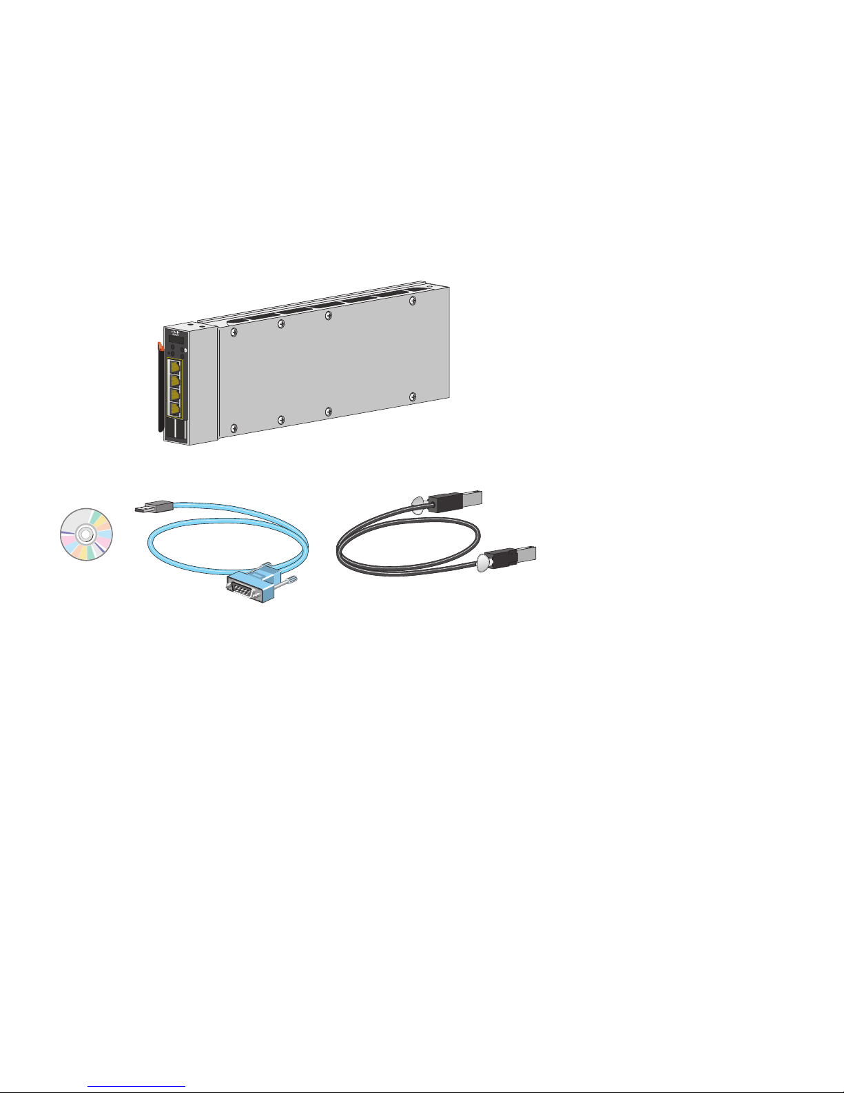
Shipping Box Contents
Figure 1 shows the Catalyst Switch Module 3110G as an example. Your switch module might look
different from the one shown.
Figure 1 Switch Module Box Contents
Catalyst Switch Module Descriptions
These sections describe the switch modules:
• Catalyst Switch Module 3110G and 3110X, page 4
• Catalyst Switch Module 3012, page 5
The switch module is powered from the blade enclosure backplane. The switch module does not have
a fan. The blade enclosure provides temperature management.
The switch module connects internally to the blade enclosure management module through
100BASE-T Ethernet links. You can manage the switch modules through the IBM advanced
Management Module (aMM) on a management network that is isolated from other switch traffic. You
can also manage the switch module through the console port on the switch module front panel or
through any of the external uplink ports.
201900
C
O
N
S
O
L
E
M
O
D
E
M
B
R
M
S
T
LNK
!
ACT
15
LNK
ACT
16
LNK
ACT
17
LNK
1 STACK 2
ACT
18
Page 4

4
Catalyst Switch Module 3110G and 3110X
The Catalyst Switch Module 3110G and 3110X are stackable, 12- to 18-Gigabit Ethernet port,
Layer 3 switch modules. The number of ports depends on the type of switch module. Up to 14 of the
Gigabit Ethernet ports are internal 1000BASE-X downlink ports that connect to the blade enclosure.
Figure 2 shows the two switch modules, and Table 1 describes the switch module ports.
Figure 2 Catalyst Switch Module 3110G and 3110X
1
Catalyst Switch Module 3110G
6
10/100/1000 Ethernet ports
2
Catalyst Switch Module 3110X
7
Switch module LEDs
3
10-Gigabit Ethernet module slot
1
1. For use with Cisco X2 transceiver modules.
8
Mode button
4
StackWise Plus ports
9
Console port
5
Release latch
201895
C
O
N
S
O
L
E
M
O
D
E
M
B
R
M
S
T
LNK
!
ACT
15
LNK
ACT
16
LNK
ACT
17
LNK
1
STA
CK 2
ACT
18
X2
C
O
N
S
O
L
E
M
O
D
E
M
B
R
M
S
T
!
1
STA
CK 2
1
4
9
6
5
8
2
7
3
Page 5

5
For more information about the features of each switch module, see the hardware installation guide
and the software configuration guide on Cisco.com.
Catalyst Switch Module 3012
The Catalyst Switch Module 3012 is an 18-Gigabit Ethernet port, Layer 3 switch module. Up to 14 of
the Gigabit Ethernet ports are internal 1000BASE-X downlink ports that connect to the blade
enclosure. The other four Gigabit Ethernet ports are external uplink ports that provide connections to
other switches or routers. Figure 3 shows the switch module, and Table 2 describes the switch module
ports.
Table 1 Catalyst Switch Module 3110G and 3110X Port Descriptions
Port Description
Ports 1 to 14
1
1. The number of internal ports is determined by the blade enclosure model. See the blade enclosure documentation for
more information about internal port numbering.
Internal Gigabit Ethernet 1000BASE-X downlink ports that connect to the
blade enclosure.
Ports 15 to 18
(Switch module 3110G)
External 10/100/1000BASE-T copper Gigabit Ethernet uplink ports that
support auto-MDIX and autonegotiation.
Port 1 (X2)
(Switch module 3110X)
External 10-Gigabit Ethernet module slot for use with Cisco X2
transceiver modules.
Internal 100BASE-T
Ethernet port
The Ethernet management port (Fa0) is used only for switch module
management traffic, not for data traffic. It is connected to the aMM
through the blade enclosure backplane connector. Traffic to and from this
port is isolated from the switch ports. This port only supports
autonegotiation with 100 Mb/s and full-duplex mode.
StackWise Plus ports Stacking cable ports.
Console port Switch module management port (USB-to-DB-9connector).
Page 6

6
For more information about the features of the switch module, see the hardware installation guide and
the software configuration guide on Cisco.com.
Figure 3 Catalyst Switch Module 3012
1
Catalyst Switch Module 3012
4
Switch module LEDs
2
Console port
5
10/100/1000 Ethernet ports
3
Mode button
6
Release latch
Table 2 Catalyst Switch Module 3012 Port Descriptions
Port Description
Ports 1 to 141Internal Gigabit Ethernet 1000BASE-X downlink ports that connect to the blade
enclosure.
Ports 15 to 18 External 10/100/1000BASE-T copper Gigabit Ethernet uplink ports that support
auto-MDIX and autonegotiation.
270430
C
O
N
S
O
L
E
M
O
D
E
LNK
!
ACT
15
LNK
ACT
16
LNK
ACT
17
LNK
ACT
18
1
2
5
6
3
4
Page 7

7
3 Installing the Switch Module
This section covers switch module installation. The illustrations in this section show the Catalyst
Switch Module 3110G as an example. The instructions are the same for the Catalyst Switch
Module 3110X and 3012.
Installation Guidelines
Consider these guidelines before you install the switch module:
• Fill any unoccupied interconnect bays or any unoccupied power module bays in the blade
enclosure with filler modules.
• Identify the bays in which you will insert the switch modules. Plan to install the first switch module
in bay 1, the second in bay 2, and so on up to bay 4, if possible.
See the IBM blade enclosure documentation for more information about the specific enclosure
model, the interconnect bay options, and the port mapping between the blade enclosure and the
switch modules. Also see the blade enclosure compatibility table in the switch module release notes
on Cisco.com.
Internal
100BASE-T
Ethernet port
The Ethernet management port (Fa0) is used only for switch module management
traffic, not for data traffic. It is connected to the aMM through the blade enclosure
backplane connector. Traffic to and from this port is isolated from the switch ports.
This port only supports autonegotiation with 100 Mb/s and full-duplex mode.
Console port Switch module management port (USB-to-DB-9 connector).
1. The number of internal ports is determined by the blade enclosure model. See the blade enclosure documentation for
more information about internal port numbering.
Table 2 Catalyst Switch Module 3012 Port Descriptions (continued)
Port Description
Page 8
8
• For switch stacks, you should first install and configure the switch module that will be the stack
master before installing any additional switch modules. See the “Creating Switch Stacks” section
on page 21 for more information.
• Review and become familiar with the safety guidelines in the Regulatory Compliance and Safety
Information for the Cisco Catalyst Switch Module 3110G, 3110X, and 3012 for IBM BladeCenter
on the documentation CD.
• Review and become familiar with the safety guidelines, and the temperature, power, and
grounding requirements specified in the IBM blade enclosure installation and user’s guide.
Installing the Switch Module
Warning
Before working on equipment that is connected to power lines, remove jewelry
(including rings, necklaces, and watches). Metal objects will heat up when connected
to power and ground and can cause serious burns or weld the metal object to the
terminals.
Statement 43
Warning
Do not work on the system or connect or disconnect cables during periods of lightning
activity.
Statement 1001
Warning
Class 1 laser product.
Statement 1008
Caution To prevent electrostatic-discharge (ESD) damage when installing switch modules, follow
your normal board and component handling procedures.
Page 9

9
Follow these steps:
Step 1 Remove the acoustic attenuation module, if one is installed, from the rear of the blade
enclosure.
Step 2 Select the blade enclosure bay in which to install the switch module (Figure 4).
Figure 4 IBM BladeCenterH Rear-Panel View
Step 3 Remove the filler module from the selected bay. Store the filler module for future use.
Step 4 If you have not already done so, touch the static-protective package that contains the switch
module to any unpainted metal surface of the blade enclosure or any unpainted metal surface
on any other grounded rack component for at least 2 seconds.
Step 5 Remove the switch module from its static-protective package.
1
I/O module bay 1
3
I/O module bay 3
2
I/O module bay 2
4
I/O module bay 4
270428
1
3
4
2
Page 10

10
Step 6 Move the switch module release latch to the open position (perpendicular to the switch
module).
Step 7 Slide the switch module into the bay until it stops (Figure 5).
Figure 5 Installing the Switch Module
Step 8 Move the switch module release latch to the closed position. After you insert and lock the
switch module, it turns on, and the power-on self-test (POST) runs to verify that the switch
module is operating correctly.
The system power LED blinks green while POST is running, and then turns solid green when
POST is finished.
Step 9 Confirm that the system power LED is green. For a complete description of the switch module
LEDs, see the hardware installation guide on Cisco.com.
Step 10 Replace the acoustic-attenuation module, if applicable.
C
O
N
S
O
L
E
M
O
D
E
M
B
R
M
S
T
LNK
!
ACT
15
LNK
ACT
16
LNK
ACT
17
LNK
1
STACK
2
ACT
18
201897
Page 11

11
4 Configuring the Switch Module
When you first set up the switch module, you should use the blade enclosure advanced Management
Module (aMM) to enter the initial IP information and the Cisco device manager Express Setup screen
to configure the switch module password and Telnet access. You can then access the switch module
through the IP address for further configuration.
Before running the setup procedures, observe these cautions:
Caution Do not connect devices to the switch module external ports until you have completed the
setup procedures and your configuration matches that of the upstream network.
Caution For Catalyst 3110G and 3110X switch modules, make sure that no StackWise Plus cables
are connected to the switch module when running the setup procedures. If StackWise Plus
cables are connected, you cannot access the switch module by using the aMM.
If you have already connected StackWise Plus cables, remove the cables, and then restart
the switch modules by removing and inserting the modules in the blade enclosure.
Assigning the Switch Module IP Address
To complete this procedure, you will need this information from your system administrator:
• Static IP address
• Default gateway IP address
Follow these steps:
Step 1 Connect and log on to the aMM as described in the IBM BladeCenter Advanced Management
Module User’s Guide.
Note The aMM web interface refers to the switch module as the I/O module.
Page 12

12
Step 2 From the I/O Module Tasks menu, click Admin/Power/Restart.
Step 3 In the I/O Module Advanced Setup section, use the Select a module pull-down menu to select
the I/O module (switch module) to configure (Figure 6).
Use the External ports pull-down menu and select Enabled to enable the switch module
external ports.
Step 4 Click Save to save your settings.
Figure 6 AMM I/O Module Admin/Power/Restart Window
Page 13
13
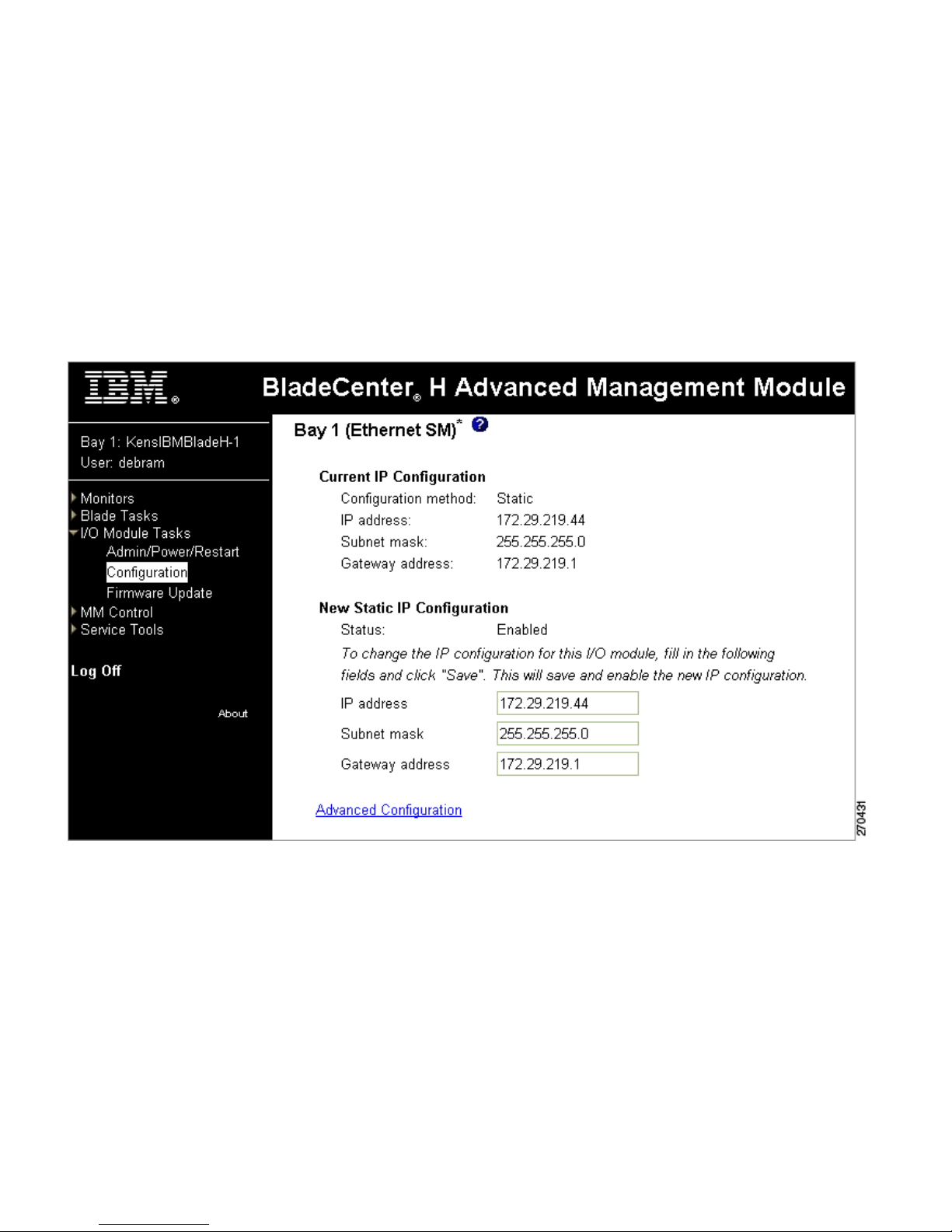
Step 5 From the I/O Module Tasks menu, click Configuration.
Step 6 In the I/O Module Configuration section, click the bay number that corresponds to the
location of the I/O module (switch module) that you are configuring. The applicable bay
number appears in the window, followed by other related I/O-module information, including
the IP address. The I/O-module information is divided into two sections: Current IP
Configuration and New Static IP Configuration (Figure 7).
Figure 7 AMM I/O Module Configuration Window
Step 7 In the New Static IP Configuration section, enter the new IP address, the subnet mask, and
the gateway address. Click Save.
The IP address for the I/O module must be on the same subnet as the management module.
The management module does not check for invalid IP addresses.
Page 14

14
Step 8 Click Advanced Configuration, and enable these switch module features:
a. External management over all ports
b. Preserve new IP configuration on all resets
The default setting is Disabled for these features.
Note If you have connected the StackWise Plus cables, the Advanced Configuration settings
are not available. To access the Advanced Configuration settings, disconnect the
StackWise Plus cables.
Step 9 Click Save to save your settings.
Step 10 Exit the aMM web interface.
Step 11 Go to “Running Express Setup” to complete the switch module setup.
Running Express Setup
To complete the Express Setup program, you will need this information from your system
administrator:
• Switch module password
• Telnet access password
• Names of the SNMP read and write community strings if you are going to use a
network-management program like CiscoWorks (optional)
• Host name, system contact, and system location (optional)
Follow these steps:
Step 1 Launch a web browser on a PC that is connected to the Internet. Enter the IP address that you
assigned in Step 7 of the “Assigning the Switch Module IP Address” procedure in the web
browser, and press Enter.
Page 15

15
Step 2 The switch module device manager page appears (Figure 8). If it does not appear, see the “In
Case of Difficulty” section on page 26.
Figure 8 Switch Module Device Manager Page
Page 16

16
Step 3 Select Configure > Express Setup from the menu. The Express Setup Basic Settings screen
appears (Figure 9).
Figure 9 Express Setup Basic Settings Screen
Step 4 Enter this information in the Network Settings fields.
–
In the Switch Password field, enter your password. The password can be from 1 to 25
alphanumeric characters, can start with a number, is case sensitive, allows embedded spaces,
but does not allow spaces at the beginning or end.
–
In the Confirm Switch Password field, enter your password again.
You can enter the Optional Settings information now or enter it later by using the switch module
device manager interface.
Step 5 In the Host Name field, enter a name for the switch module. The host name is limited to
31 characters; embedded spaces are not allowed.
Step 6 In the System Date and System Time fields, enter the current date and time, or use the down
arrows to select them.
Step 7 In the Time Zone field, use the down arrow to choose your time zone.
Step 8 Click Enable in the Daylight Savings Time field to enable this feature.
Page 17

17
Step 9 Select the Advanced Settings tab on the Express Setup screen. The Advanced Settings screen
appears (Figure 10).
Figure 10 Express Setup Advanced Settings Screen
Step 10 In the Telnet Access field, click Enable if you are going to use Telnet to manage the switch
module by using the CLI. If you enable Telnet access, you must enter a Telnet password.
Step 11 In the Telnet Password field, enter a password. The Telnet password can be from 1 to 25
alphanumeric characters, is case sensitive, allows embedded spaces, but does not allow spaces
at the beginning or end. In the Confirm Telnet Password field, re-enter the Telnet password.
Step 12 In the SNMP field, click Enable to enable Simple Network Management Protocol (SNMP).
Enable SNMP only if you plan to manage switch modules by using CiscoWorks 2000 or
another SNMP-based network-management system.
Step 13 If you enable SNMP, you must enter a community string in the SNMP Read Community field,
the SNMP Write Community field, or both. SNMP community strings authenticate access to
MIB objects. Embedded spaces are not allowed in SNMP community strings. When you set
the SNMP read community, you can access SNMP information, but you cannot modify it.
When you set the SNMP write community, you can both access and modify SNMP
information.
Step 14 In the System Contact field, enter the name of the person who is responsible for the switch
module. In the System Location field, enter the wiring closet, floor, or building where the
switch module is located.
Page 18

18
Step 15 (Optional) You can enable IPv6 in the IPv6 Settings section. Click Enable IPv6 to enable it. In
the Interface column, choose the interface for which you want to set an IPv6 address, and
complete the other fields in this table.
Step 16 Click Submit to save your settings, or click Cancel to clear your settings. When you click
Submit, you have completed the switch module initial configuration.
To install and configure additional switch modules, repeat the steps in the “Installing the Switch
Module” through the “Configuring the Switch Module” sections.
See “Connecting Devices” for more information about connecting to network devices.
See “Creating Switch Stacks” for more information about creating switch stacks.
Designating the Switch Stack Master
This section is only for the Catalyst Switch Module 3110G and 3110X and is optional.
If you plan to create a switch stack, we recommend that you set the switch module that you first
configure as the stack master. To do this, you must assign the highest priority value to this switch
module after installation and setup.
Follow these steps:
Step 1 Start a Telnet session from a remote management station and connect to the switch module.
Step 2 At the prompt, enter enable.
Step 3 Enter configure terminal.
Step 4 Enter switch 1 priority 15.
Step 5 At the prompt, press Return.
Step 6 Enter end.
Step 7 Enter copy running-configuration startup-configuration to save this setting.
Step 8 At the prompt, press Return.
Step 9 To verify that this switch module is set as the stack master, enter the show switch user EXEC
command.
See “Creating Switch Stacks” for more information about creating switch stacks.
Page 19

19
5 Managing the Switch Module
After you complete the initial switch module configuration, use the aMM, the CLI, the switch module
device manager, or the other management options described in this section for further configuration.
Blade Enclosure Advanced Management Module
For standalone switch modules, you can use the aMM to configure and manage the switch module.
See the IBM BladeCenter Advanced Management Module User’s Guide for more information. For
stacked switch modules, use the CLI, the switch device manager, or the Cisco Network Assistant to
configure and manage the switch stack.
Command-Line Interface
You can enter Cisco IOS commands and parameters through the CLI. You can access the CLI by
connecting your management station directly to the switch module console port or by using Telnet
from a remote management station.
To connect to the switch module console port, follow these steps:
1. Connect the supplied USB-to-DB-9 adapter cable to the serial port on the PC. Connect the USB
end of the cable to the console port on the switch module.
2. Start a terminal-emulation program on the PC.
3. Configure the PC terminal emulation software for 9600 baud, 8 data bits, no parity, 1 stop bit,
and no flow control.
4. Use the CLI to enter commands to configure and manage the switch module and switch stacks. See
the software configuration guide and the command reference on Cisco.com for more information.
Page 20

20
Switch Module Device Manager
You can use the device manager (Figure 8) that is in the switch module memory to manage a
standalone switch module or a switch stack. You can access the device manager from anywhere in your
network through a web browser.
Follow these steps:
1. Launch a web browser on your PC or workstation.
2. Enter the switch module IP address in the web browser, and press Enter. The device manager page
appears.
3. Use the device manager to perform basic switch module configuration and monitoring. Refer to
the device manager online help for more information.
Cisco Network Assistant
Cisco Network Assistant is a software program that you download from Cisco.com and run on
your PC. It offers advanced options for configuring and monitoring multiple devices, including switch
modules, switch clusters, routers, and access points. Network Assistant is free—there is no charge to
download, install, or use it.
Follow these steps:
1. Go to this web address: http://www.cisco.com/go/NetworkAssistant.
You must be a registered Cisco.com user, but you need no other access privileges.
2. Find the Network Assistant installer.
3. Download the Network Assistant installer, and run it. (You can run it directly from the web if your
browser offers this choice.)
4. When you run the installer, follow the displayed instructions. In the final panel, click Finish to
complete the Network Assistant installation.
Refer to the Network Assistant online help and the getting started guide for more information.
Other Management Options
You can use SNMP management applications such as CiscoWorks Small Network Management
Solution (SNMS) and IBM Director to configure and manage the switch module.
Page 21

21
6 Creating Switch Stacks
This section is only for the Catalyst Switch Module 3110G and 3110X and is optional.
A switch stack is a set of up to nine stacking-capable switch modules that are connected through their
StackWise Plus ports. One switch module controls the operation of the stack and is called the stack
master. The stack master and the other switch modules in the stack are stack members. Layer 2 and
Layer 3 protocols present the entire switch stack as a single entity to the network. When switch
modules are not stacked, each acts as a standalone switch module.
Caution The Catalyst Switch Module 3110G and 3110X do not support switch stacks with other
types of blade switches as members. Combining the switch module with other types of
blade switches in a switch stack might cause the switch module to work improperly or to
fail.
Stacking Guidelines
Before you connect the switch modules in a stack, observe these stacking guidelines:
• You should install the stack master switch module and run the initial setup program on that switch
module before you connect the StackWise Plus cables to other stack members. We recommend that
you assign the highest priority value to the switch module that you prefer to be the stack master.
This ensures that the switch module is re-elected as stack master if a re-election occurs. As you
add new switch modules to the stack, they automatically become stack members.
To assign a priority value after you have installed and initially configured the first switch module,
see the “Designating the Switch Stack Master” section on page 18.
• When you connect the StackWise Plus cables and create a stack, only the status of the stack master
Fa0 interface appears in the switch module configuration, and it will show that the port is shut
down while in stack mode.
• You can stack a combination of up to nine switch modules. You can stack only the Catalyst Switch
Modules 3110G and 3110X; other blade switches are not supported.
• For conditions that might cause a stack master re-election and for general concepts and procedures
to manage switch stacks, see the “Managing Switch Stacks” chapter in the switch module software
configuration guide on Cisco.com.
Page 22

22
• Before connecting, verify the StackWise Plus cable length. Depending on your configuration, you
might need different sized cables. If you do not specify the length of the StackWise Plus cable when
you order your product, the 1-meter cable is supplied. If you need the 0.5-meter cable or the
3-meter cable, you can order these StackWise Plus cables from your supplier:
–
CAB-STK-E-0.5M= (0.5-meter cable)
–
CAB-STK-E-1M= (1-meter cable)
–
CAB-STK-E-3M= (3-meter cable)
Connecting a Switch Stack
Follow these steps:
Step 1 Install the member switch modules if you have not already done so.
Step 2 Remove the dust covers from the StackWise Plus cables, and store them for future use.
Step 3 Verify that cables are aligned as shown in Figure 11. (The cables are keyed for correct
insertion.)
Figure 11 Connecting the StackWise Plus Cables
C
O
N
S
O
L
E
M
O
D
E
M
B
R
M
S
T
LNK
!
ACT
15
LNK
ACT
16
LNK
ACT
17
LNK
1
STACK
2
ACT
18
201898
Page 23

23
Step 4 Insert the cable into the StackWise Plus port on the front panel of the switch module. Insert
the other end of the cable into the connector of the other switch module.
Always use a Cisco-approved StackWise Plus cable to connect the switch modules.
Caution The new stack-member switch module restarts when you connect the StackWise Plus
cables.
Step 5 Configure the member switch modules through the master switch by using the CLI through
the console port of any stack member.
To remove the StackWise Plus cables, grasp the tab on the cable connector, and gently pull straight
out. When you remove the StackWise Plus cables, replace the dust covers to protect them from dust.
Caution Removing and installing the StackWise Plus cable can shorten its useful life. Do not
remove and insert the cable more often than is absolutely necessary.
Switch Stack Cabling Example
Figure 12 shows a single blade enclosure with two switch modules that create one stack. The stack
uses the 1-meter StackWise Plus cables to make redundant connections between two switch modules.
Other types of configurations are possible if you stack no more than nine switch modules. Although
the StackWise Plus ports are numbered (1 and 2), you do not need to make specific port connections
between switch modules.
Page 24

24
For more stacking configuration examples, see the switch module hardware installation guide and the
software configuration guide on Cisco.com.
Figure 12 Switch Stack Cabling Example
270429
Page 25

25
7 Connecting Devices
This section describes how to connect to the fixed switch module ports and to the 10-Gigabit Ethernet
module slot.
Connect to 10/100/1000 Ports
The 10/100/1000 Ethernet ports use standard RJ-45 connectors with Ethernet pinouts. The maximum
cable length is 328 feet (100 meters). The 100BASE-TX and 1000BASE-T traffic requires Category 5,
Category 5e, or Category 6 UTP cable. The 10BASE-T traffic can use Category 3 or Category 4 cable.
The autonegotiation feature is enabled by default on the switch module. At this setting, the switch
module ports configure themselves to operate at the speed of attached devices. If the attached device
does not support autonegotiation, you can explicitly set the switch module port speed and the duplex
parameters. To maximize performance, either allow the ports to autonegotiate both speed and duplex,
or set the port speed and duplex parameters on both ends of the connection.
For simplified cabling, the automatic medium-dependent interface crossover (auto-MDIX) feature is
enabled by default on the switch module. With auto-MDIX enabled, the switch module detects the
required cable type for copper Ethernet connections and configures the interface accordingly.
Therefore, you can use either a crossover or a straight-through cable for connections to a switch
module 10/100/1000 Ethernet port, regardless of the type of device on the other end of the connection.
For more information about enabling or disabling autonegotiation and auto-MDIX, see the switch
module software configuration guide or the command reference on Cisco.com.
Install and Connect to Devices in the 10-Gigabit Ethernet Slot
The switch module 10-Gigabit Ethernet module slot is used for connections to other switches
and routers. The module slot operates in full-duplex mode and uses the hot-swappable Cisco X2
transceiver module. The X2 transceiver module has SC connectors to connect to multimode fiber
(MMF) and single-mode fiber (SMF) cables.
Use only Cisco X2 transceiver modules with the switch module. Each Cisco module has an internal
serial EEPROM that is encoded with security information. This encoding provides a way for Cisco to
identify and validate that the module meets the requirements for the switch module.
Page 26

26
Verify Port Connectivity
After you connect a device to a switch module port, the port LED is off while the switch module
establishes a link. This process takes about 30 seconds. Then the LED turns green when the switch
module and the attached device have an established link. If the LED is off, the device might not be
turned on, there might be a cable problem, or there might be a problem with the adapter installed in
the device. See the “In Case of Difficulty” section on page 26 for more information.
8 In Case of Difficulty
If you experience difficulty, help is available in this section and also on Cisco.com. You can access the
Cisco Technical Support and Documentation website for a list of known hardware problems and
extensive troubleshooting documentation at:
http://www.cisco.com/en/US/support/index.html
For more information about the IBM blade enclosure, see the IBM blade enclosure website at:
http://www-03.ibm.com/systems/bladecenter/
Troubleshooting Switch Module Setup
Review this section if you are having trouble running the initial setup procedures:
• Did you try to access the switch module
through the aMM before installing the
switch module in the blade enclosure?
If yes, install the switch module as described in
the “Installing the Switch Module” section on
page 7.
• Did you verify that POST successfully ran on
the switch module before accessing the
switch through the aMM?
If not, make sure that the switch module System
power LED is green before using the aMM to
access the switch module.
• Did you try to access the switch module
through the aMM after connecting the
StackWise Plus cables?
If yes, disconnect the StackWise Plus cables.
Remove the switch module, and then reinstall the
switch module. Follow the procedures described
in the “Configuring the Switch Module” section
on page 11.
• When accessing the switch module device
manager, did you enter the wrong address in
the browser, or is there an error message?
If yes, re-enter the switch module IP address in the
browser, and press Enter.
Page 27

27
Resetting the Switch Module
For a standalone switch module, you can perform these functions by using the aMM web interface:
• Reboot the switch module
• Restore factory defaults
• Set or reset the IP address, netmask, and default gateway
• Enable or disable external ports
• Enable or disable management through the external ports
• Change configuration
• Change or update firmware
For a switch stack, you can use the CLI to perform the same functions. For more information, see the
switch module software configuration guide and command reference on Cisco.com.
Using the Mode Button to Reset the Switch Module
You can use the Mode button to reset a standalone switch module.
Caution For a standalone switch module, resetting the switch module deletes the configuration
and reboots the switch module.
For a standalone switch module, use a small pointed object to press and hold the Mode button on the
switch module front panel. The switch module LEDs begin blinking after about 3 seconds. Continue
holding down the Mode button. The LEDs stop blinking after 7 more seconds, and then the switch
module reboots.
The switch module is now unconfigured. You can enter the switch module IP information by following
the procedures described in the “Configuring the Switch Module” section.
For switch stacks, pressing and holding the Mode button on a member switch module causes the stack
to reboot. It does not remove the configuration from any member switch.
Page 28

28
For More Information
For more information about the switch module, see these documents on Cisco.com:
• Cisco Catalyst Switch Module 3110G, 3110X, and 3012 for IBM BladeCenter Software
Configuration Guide. This guide provides a product overview and detailed descriptions and
procedures for the switch module software features.
• Cisco Catalyst Switch Module 3110G, 3110X, and 3012 for IBM BladeCenter Command
Reference. This reference provides detailed descriptions of the Cisco IOS commands specifically
created or modified for the switch module.
• Cisco Catalyst Switch Module 3110G, 3110X, and 3012 for IBM BladeCenter System Message
Guide. This guide provides descriptions of the system messages specifically created or modified
for the switch module.
• Cisco Software Activation Document for IBM BladeCenter. This document describes the
supported feature sets, software licenses, and information about using software activation in
mixed software switch stacks.
• Cisco Catalyst Switch Module 3110G, 3110X, and 3012 for IBM BladeCenter Hardware
Installation Guide. This guide provides complete hardware descriptions and detailed installation
procedures.
• Regulatory Compliance and Safety Information for the Cisco Catalyst Switch Module 3110G,
3110X, and 3012 for IBM BladeCenter. This guide contains agency approvals, compliance
information, and translated warning statements.
• Release Notes for the Cisco Catalyst Switch Module 3110G, 3110X, and 3012 for IBM
BladeCenter. The release notes include the system requirements, important notes, limitation, open
and resolved caveats, and documentation updates.
9 Obtaining Documentation, Obtaining Support, and
Security Guidelines
For information on obtaining documentation, obtaining support, providing documentation feedback,
security guidelines, and also recommended aliases and general Cisco documents, see the monthly
What's New in Cisco Product Documentation, which also lists all new and revised Cisco technical
documentation, at:
http://www.cisco.com/en/US/docs/general/whatsnew/whatsnew.html
Page 29

29
Page 30

Americas Headquarters
Cisco Systems, Inc.
170 West Tasman Drive
San Jose, CA 95134-1706
USA
www.cisco.com
Tel: 408 526-4000
800 553-NETS (6387)
Fax: 408 527-0883
Asia Pacific Headquarters
Cisco Systems (USA) Pte. Ltd.
168 Robinson Road
#28-01 Capital Tower
Singapore 068912
www.cisco.com
Tel: +65 6317 7777
Fax: +65 6317 7799
Europe Headquarters
Cisco Systems International BV
Haarlerbergpark
Haarlerbergweg 13-19
1101 CH Amsterdam
The Netherlands
www-europe.cisco.com
Tel: 31 0 800 020 0791
Fax: 31 0 20 357 1100
Cisco has more than 200 offices worldwide. Addresses, phone numbers, and fax numbers are listed on the
Cisco Website at www.cisco.com/go/offices.
CCDE, CCVP, Cisco Eos, Cisco StadiumVision, the Cisco logo, DCE, and Welcome to the Human Network are trademarks; Changing the Way We
Work, Live, Play, and Learn is a service mark; and Access Registrar, Aironet, AsyncOS, Bringing the Meeting To You, Catalyst, CCDA, CCDP,
CCIE, CCIP, CCNA, CCNP, CCSP, Cisco, the Cisco Certified Internetwork Expert logo, Cisco IOS, Cisco Press, Cisco Systems, Cisco Systems
Capital, the Cisco Systems logo, Cisco Unity, Collaboration Without Limitation, Enterprise/Solver, EtherChannel, EtherFast, EtherSwitch, Event
Center, Fast Step, Follow Me Browsing, FormShare, GigaDrive, HomeLink, Internet Quotient, IOS, iPhone, IP/TV, iQ Expertise, the iQ logo, iQ
Net Readiness Scorecard, iQuick Study, IronPort, the IronPort logo, LightStream, Linksys, MediaTone, MeetingPlace, MGX, Networkers,
Networking Academy, Network Registrar, PCNow, PIX, PowerPanels, ProConnect, ScriptShare, SenderBase, SMARTnet, Spectrum Expert,
StackWise, The Fastest Way to Increase Your Internet Quotient, TransPath, WebEx, and the WebEx logo are registered trademarks of Cisco Systems,
Inc. and/or its affiliates in the United States and certain other countries.
All other trademarks mentioned in this document or Website are the property of their respective owners. The use of the word partner does not imply
a partnership relationship between Cisco and any other company. (0801R)
© 2008 Cisco Systems, Inc. All rights reserved.
78-18008-01
 Loading...