

Page 1
Catalyst 2960-S Switch
Getting Started Guide
• About This Guide
• Unpacking the Switch
• Running Express Setup
• Managing the Switch
• Planning and Creating Switch Stacks
• Rack-Mounting
• Connecting the FlexStack Cables
• Connecting to the Switch Ports
OL-19793-02
• In Case of Difficulty
• Obtaining Documentation and Submitting a Service Request
Catalyst 2960-S Switch Getting Started Guide
1
Page 2

About This Guide
This guide provides instructions on how to use Express Setup to initially
configure your Catalyst switch. It also covers switch management options, basic
rack-mounting, stacking guidelines, port and module connection procedures, and
troubleshooting help.
For additional installation and configuration information for the switch, see the
Catalyst 2960 documentation on Cisco.com. For system requirements, important
notes, limitations, open and resolved bugs, and last-minute documentation
updates, see the release notes, also on Cisco.com. For translations of the warnings
that appear in this publication, see the Regulatory Compliance and Safety
Information for the Catalyst 2960 and 2960-S Switches on Cisco.com.
When using the online publications, see the documents that match the Cisco IOS
software version running on the switch. The software version is on the Cisco IOS
label on the switch rear panel.
Unpacking the Switch
Catalyst 2960-S Switch Getting Started Guide
Follow these steps:
1. Unpack and remove the switch and the accessory kit from the shipping box.
2. Return the packing material to the shipping container, and save it for future
use.
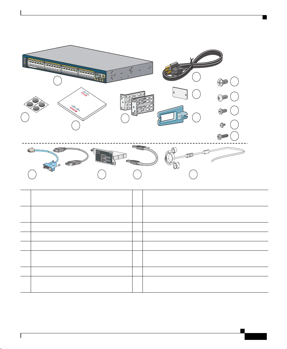
3. Verify that you have received these items. If any item is missing or damaged,
contact your Cisco representative or reseller for instructions.
Catalyst 2960-S Switch Getting Started Guide
2
OL-19793-02
Page 3
Catalyst 2960-S Switch Getting Started Guide
Catalyst 2960-S Switch
Documentation
Catalyst 2960-S
Series
PoE+ 10G
11X
2X
1X
11X
14X
12X
13X
23X
2
4
X
25X
26X
3
7
X
39X
36X
38X
47X
48X
1
2
P
OWER
OVER
ETHERNET 740W
8
9
10
4
5
6
11
13
2
7
12
1
3
14 15 16
206224
1 Catalyst 2960-S switch
1
9 Four number-8 Phillips truss-head screws
(48-0656-01)
2 AC power cord 10 Four number-8 Phillips flat-head screws
(48-0655-01)
3 Four rubber mounting feet 11 Two number-4 pan-head screws (48-0482-01)
4 Documentation 12 One black Phillips machine screw (48-0654-01)
5 Two 19-inch mounting brackets 13 (Optional3) Console cable or USB cable
6 Connector2 cover for redundant power
system
14 (Optional3) Cisco FlexStack module
7 Cable guide 15 (Optional3) Cisco FlexStack cable
8 Four number-12 Phillips pan-head screws
(48-0523-01)
1. Catalyst 2960S-48FPD-L switch shown for example. Your switch model might look different.
2. Only available on some models.
3. Item is orderable.
OL-19793-02
16 (Optional3) Power cord retainer
Catalyst 2960-S Switch Getting Started Guide
3
Page 4
Running Express Setup
When you first set up the switch, you should use Express Setup to enter the initial
IP information. Doing this enables the switch to connect to local routers and the
network. You can then access the switch through the IP address for further
configuration.
You need this equipment to set up the switch:
• A PC with Windows 2000, XP, Vista, or Windows Server 2003 installed
• A web browser (Internet Explorer 6.0, 7.0, Firefox 1.5, 2.0, or later) with
JavaScript enabled
Note Other laptops and browsers might work.
• A straight-through or crossover Category 5 or 6 Ethernet cable to connect
your PC to the switch
Catalyst 2960-S Switch Getting Started Guide
Step 1
Step 2
4
Note Before running Express Setup, disable any pop-up blockers or proxy settings in
your browser software and any wireless client running on your PC.
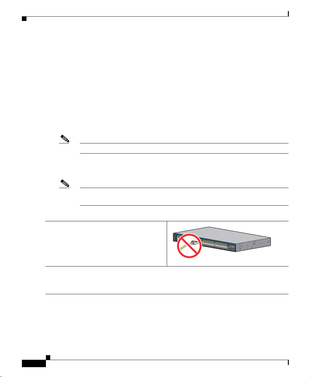
Make sure that nothing is connected to the
switch.
1X
11X
11X
13X
2X
23X
25X
12X
14X
36X
38X
24X
26X
Catalyst 2960-S
Series
PoE+ 10G
47X
37X
39X
48X
1
2
206225
During Express Setup, the switch acts as a DHCP server. If your PC has a static IP address,
temporarily configure your PC settings to use DHCP before proceeding to the next step.
Note Write down the static IP address. You will need this IP address in Step 10.
Catalyst 2960-S Switch Getting Started Guide
OL-19793-02
Page 5
Catalyst 2960-S Switch Getting Started Guide
RATING
100-240~
12-6A, 50-60Hz
206226
Step 3
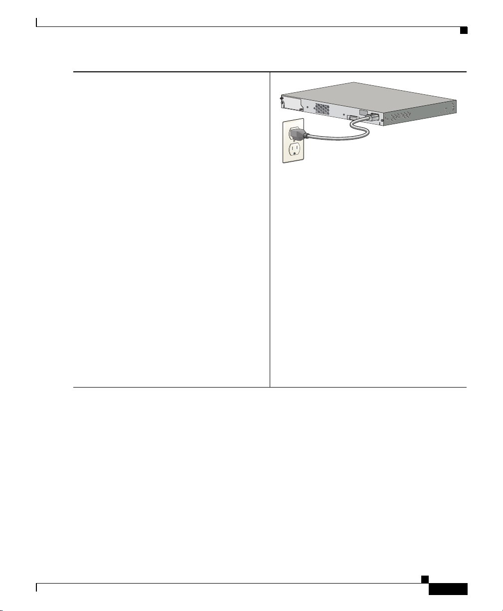
Power the switch by connecting the AC power
cord to the switch power supply and to a
grounded AC outlet.
Approximately 30 seconds after the switch
powers on, it begins the power-on self-test
(POST), which can take several minutes to
complete.
During POST, the SYSTEM LED blinks
green, and the RPS, STATUS, DUPLEX, and
SPEED LEDs turn solid green.
When POST is complete, the SYSTEM LED
remains solid green, and the other LEDs go
off. The exception is the STACKMASTER
LED, which remains solid green if the switch
is stackable and is acting as stack master.
Before proceeding to the next step, wait until
POST is complete. This might take up
to
5 minutes after the switch is powered on.
Troubleshooting:
If the SYSTEM LED blinks green, does not turn
solid green, or turns amber, contact your Cisco
representative or reseller. The switch failed the
power-on self-test (POST).
OL-19793-02
Catalyst 2960-S Switch Getting Started Guide
5
Page 6
Catalyst 2960-S Switch Getting Started Guide
Catalyst 2960-S
Series
PoE+ 10G
1
1X
2
X
1
X
1
1X
14X
1
2X
1
3
X
23X
24
X
2
5X
26X
37
X
39X
36
X
38X
47X
48
X
1
2
206598
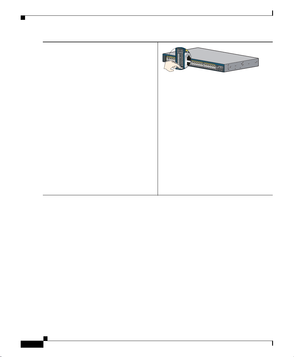
Step 4
Press and hold the Mode button until all of the
LEDs above the Mode button turn solid green.
You might need to hold the button for 3 or
more seconds.
Release the Mode button after all of the LEDs
above the Mode button turn solid green. (The
RPS LED remains off on some switch models,
and is not present on all models.)
The switch is now in Express Setup mode.
Before proceeding to the next step, make sure
that all of the LEDs above the Mode button
are solid green.
Troubleshooting:
If the LEDs above the Mode button blink after
you press the button, release it. Blinking
LEDs mean that the switch is already
configured and cannot go into Express Setup
mode. For more information, see the
“Resetting the Switch” section on page 28.
6
Catalyst 2960-S Switch Getting Started Guide
OL-19793-02
Page 7
Catalyst 2960-S Switch Getting Started Guide
Catalyst 2960XS
Se
ri
es
PoE 10G
11X
2
X
1
X
11X
14X
12X
1
3X
23X
2
4X
25
X
26
X
37X
3
9
X
36X
3
8
X
47X
48
X
1
2
206228
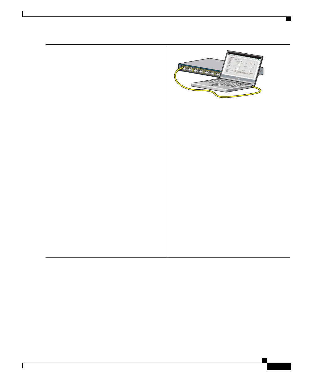
Step 5
Connect a Category 5 or 6 Ethernet cable to
one of these locations:
• Any 10/100 or 10/100/1000 Ethernet
downlink port (such as port 1) on the
switch front panel.
• The Ethernet management port on the
switch front panel.
Connect the other end of the cable to the
Ethernet port on your PC.
Before proceeding to the next step, wait until
the port LEDs on the switch and your PC or
laptop are green (either solid or blinking).
The green port LEDs indicate a successful
connection.
Troubleshooting:
If the port LEDs do not turn green after about
30 seconds, make sure that:
• You connected the Ethernet cable to one
of the downlink switch ports (not to an
uplink port such as the dual-purpose
port).
• You are using an undamaged Category 5
or 6 Ethernet cable.
• The other device is turned on.
OL-19793-02
Catalyst 2960-S Switch Getting Started Guide
7
Page 8
Catalyst 2960-S Switch Getting Started Guide
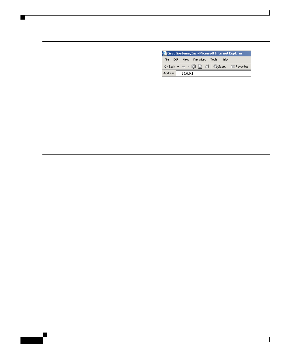
Step 6
Enter the IP address 10.0.0.1 in a web browser
and press Enter.
When prompted, enter the default password,
cisco.
Note The switch ignores text in the
username field.
The Express Setup window appears.
Troubleshooting:
If the Express Setup window does not appear,
make sure that any pop-up blockers or proxy
settings on your browser are disabled and that
any wireless client is disabled on your PC or
laptop.
Catalyst 2960-S Switch Getting Started Guide
8
OL-19793-02
Page 9

Catalyst 2960-S Switch Getting Started Guide
Step 7
Enter the required settings in the Express Setup window.
Note All entries must be in English letters and numbers.
Required Fields
Enter this information in the Network Settings fields:
• In the Management Interface (VLAN ID) field, the default is 1.
Note We recommend using the default VLAN value because during Express Setup, VLAN
1 is the only VLAN on the switch.
Enter a new VLAN ID only if you want to change the management interface through
which you manage the switch. The VLAN ID range is 1 to 1001.
• In the IP Address field, enter the IP address of the switch.
• In the Subnet Mask field, click the drop-down arrow, and select a subnet mask.
• In the Default Gateway field, enter the IP address for the default gateway (router).
• Enter your password in the Switch Password field. The password can be from 1 to 25
alphanumeric characters, can start with a number, is case sensitive, allows embedded
spaces, but does not allow spaces at the beginning or end. In the Confirm Switch
Password field, enter your password again.
Note You must change the password from the default password, cisco.
Optional Fields
You can enter other administrative settings in the Express Setup window. For example, the
optional administrative settings identify and synchronize the switch for enhanced
management. The switch clock is automatically synchronized with the network clock by using
NTP. You can manually set the system clock settings if the switch should have different time
settings.
Click Submit to save your changes and to complete the initial setup.
Step 8
OL-19793-02
For more information about the Express Setup fields, see the online help for the Express Setup
window.
After you click Submit, these events occur:
• The switch is configured and exits Express Setup mode.
• The browser displays a warning message and tries to connect with the earlier switch IP
address. Typically, connectivity between the PC and the switch is lost because the
configured switch IP address is in a different subnet from the IP address on the PC.
Catalyst 2960-S Switch Getting Started Guide
9
Page 10

Catalyst 2960-S Switch Getting Started Guide
Step 9
Step 10
Step 11
Disconnect the switch from the PC, and install the switch in your network. See the
“Rack-Mounting” section on page 18.
If you changed the static IP address on your PC in Step 2, change it back to the previously
configured static IP address.
You can now manage the switch by using Cisco Network Assistant, Device Manager, or both.
See the
“Managing the Switch” section on page 11 for information about configuring and
managing the switch.
We strongly recommend that you download Cisco Network Assistant from Cisco.com and use
it to manage the switch. See the
“Managing the Switch” section on page 11 for information
about configuring and managing the switch.
You can display Device Manager by following these steps:
1. Start a web browser on your PC or laptop.
2. Enter the switch IP address, username, and password (assigned in Step 7) in the web
browser, and press Enter. The Device Manager page appears.
Troubleshooting:
If Device Manager does not appear:
• Confirm that the port LED for the switch port connected to your network is green.
• Confirm that the PC or laptop you are using to access the switch has network connectivity
by connecting to a well-known web server in your network. If there is no network
connection, troubleshoot the network settings on the PC or laptop.
• Make sure that the switch IP address in the browser is correct.
• If switch IP address in the browser is correct, the switch interface LED is green, and the
PC or laptop has network connectivity, continue troubleshooting by reconnecting the PC
or laptop to the switch. Configure a static IP address on the PC or laptop that is in the
same subnet as the switch IP address. For example:
–
If your switch IP address is 172.20.20.85 and your PC or laptop IP address is
172.20.20.84, both devices are in the same network.
–
If your switch IP address is 172.20.20.85 and your PC or laptop IP address is
10.0.0.2, the devices are in different networks and cannot communicate directly.
• When the LED on the switch port connected to the PC or laptop is green, reenter the IP
address of the switch in a web browser to display Device Manager. Once Device Manager
appears, you can continue with the switch configuration.
Catalyst 2960-S Switch Getting Started Guide
10
OL-19793-02
Page 11

Catalyst 2960-S Switch Getting Started Guide
Managing the Switch
After completing Express Setup and installing the switch in your network, you
can use one of these options for further configuration:
• Device Manager
• Cisco Network Assistant
• Command-Line Interface
• Other Management Options
Device Manager
The simplest way to manage the switch is by using Device Manager in the switch
memory. This web interface offers quick configuration and monitoring. You can
access Device Manager from anywhere in your network through a web browser.
1. Launch a web browser on your PC or workstation.
2. Enter the switch IP address in the web browser, and press Enter. The Device
Manager page appears.
3. Use Device Manager to perform basic switch configuration and monitoring.
See the Device Manager online help for more information.
4. For more advanced configuration, download and run Cisco Network
Assistant, which is described in the next section.
Cisco Network Assistant
Cisco Network Assistant is a software program that you download from
Cisco.com and run on your
monitoring multiple devices, including switches, switch clusters, switch stacks,
routers, and access points. Cisco Network Assistant is free—there is no charge to
download, install, or use it.
1. Go to this Web address:
http://www.cisco.com/en/US/products/ps5931/tsd_products_support_series_
home.html.
OL-19793-02
PC. It offers advanced options for configuring and
Catalyst 2960-S Switch Getting Started Guide
11
Page 12

You must be a registered Cisco.com user, but you need no other access
privileges.
2. Find the Network Assistant installer.
3. Download the Network Assistant installer and run it. (You can run it directly
from the Web if your browser offers this choice.)
4. When you run the installer, follow the displayed instructions. In the final
panel, click Finish to complete the Network Assistant installation.
See the Network Assistant online help and the getting started guide for more
information.
Command-Line Interface
You can enter Cisco IOS commands and parameters through the CLI. Access the
CLI by using one of these options:
• Switch Console Port
• Switch Ethernet Management Port
• Switch USB Port
Catalyst 2960-S Switch Getting Started Guide
12
Catalyst 2960-S Switch Getting Started Guide
OL-19793-02
Page 13

Catalyst 2960-S Switch Getting Started Guide
Switch Console Port
1. Connect the supplied RJ-45-to-DB-9 adapter cable to the standard 9-pin
serial port on the PC. Connect the other end of the cable to the console port
on the switch.
2. Start a terminal-emulation program on the PC.
3. Configure the PC terminal emulation software for 9600 baud, 8 data bits, no
parity, 1 stop bit, and no flow control.
4. Use the CLI to enter commands to configure the switch. See the software
configuration guide and the command reference for more information.
Switch Ethernet Management Port
1. Connect a Category 5 Ethernet cable to the PC Ethernet port. Connect the
other end of the cable to the Ethernet management port on the switch.
2. Start a Telnet session on the PC.
3. Enter the switch IP address that you assigned by using Express Setup.
Switch USB Port
OL-19793-02
4. Use the CLI to enter commands to configure the switch. See the software
configuration guide and the command reference for more information.
1. Connect an USB cable to the PC USB port. Connect the other end of the cable
to the mini B (5-pin-connector) USB port on the switch.
2. Start a terminal-emulation program on the PC.
3. Configure the PC terminal emulation software for 9600 baud, 8 data bits, no
parity, 1 stop bit, and no flow control.
4. Use the CLI to enter commands to configure the switch. See the software
configuration guide and the command reference for more information.
Note You cannot use the switch console port and the switch USB port at the
same time to access the CLI.
Catalyst 2960-S Switch Getting Started Guide
13
Page 14

Catalyst 2960-S Switch Getting Started Guide
Other Management Options
You can use SNMP management applications such as CiscoWorks LAN
Management Solution (LMS) and Cisco netManager to configure and manage the
switch. You also can manage it from an SNMP-compatible workstation that is
running platforms such as Cisco netManager or SunNet Manager.
The Cisco Configuration Engine is a network management device that works with
embedded Cisco Networking Services (CNS) agents in the switch software. You
can use it to automate initial configurations and configuration updates on the
switch.
See the “Accessing Help Online” section on page 28 for a list of supporting
documentation.
Planning and Creating Switch Stacks
Note This section applies only to the Catalyst 2960-S stacking switches.
14
Before connecting the switches in a stack, keep in mind these switch stack
guidelines:
• Connect only Catalyst 2960-S switches in a switch stack.
• Install the FlexStack module and the FlexStack cable for stacking capability.
You can order them in a kit from your Cisco sales representative:
C2960S-STACK=.
• Consider the length of FlexStack cable. Depending on your configurations,
you might need different sized cables.
sales representative:
–
CAB-STK-E-0.5M= (0.5-meter cable)
–
CAB-STK-E-1M= (1-meter cable)
–
CAB-STK-E-3M= (3-meter cable)
For additional stacking guidelines, see the switch hardware installation guide on
Cisco.com. For concepts and procedures to manage switch stacks, see the switch
software configuration guide on Cisco.com.
Catalyst 2960-S Switch Getting Started Guide
You can order them from your Cisco
OL-19793-02
Page 15
Catalyst 2960-S Switch Getting Started Guide
RATING
100-240~
12-6A, 50-60Hz
206239
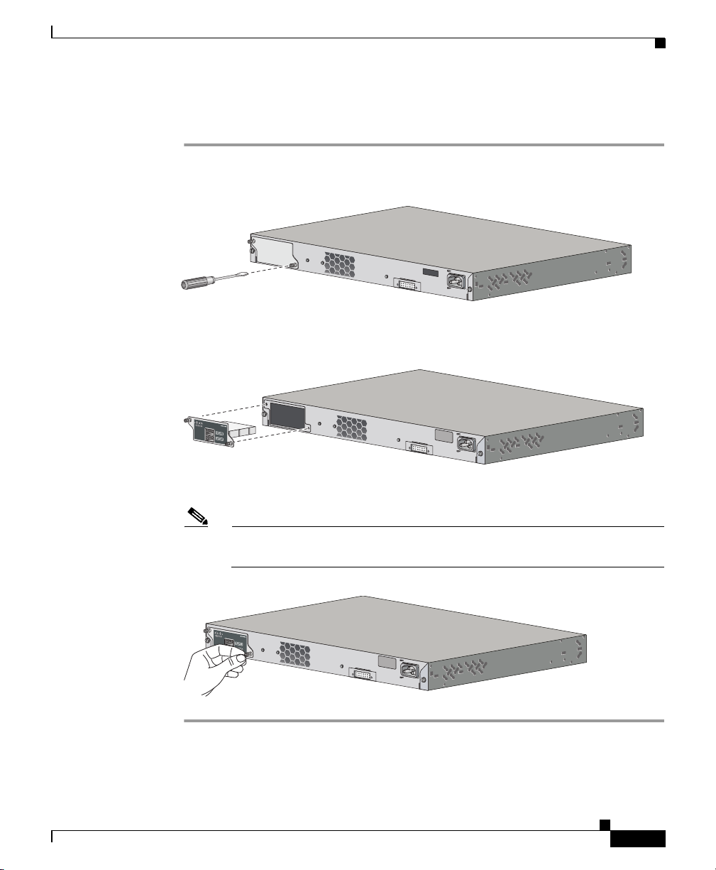
Installing the FlexStack Module
Step 1 Use a flat-blade screwdriver to remove the FlexStack module blank cover on the
switch back panel.
Step 2 Grasp the FlexStack module on the sides, and insert it into the module slot.
RATING
100-240~
12-6A, 50-60Hz
32
2062
OL-19793-02
Step 3 Secure the screws tightly on each side of the module.
Note Make sure the screws are finger-tight to avoid overtightening of the
screws.
Catalyst 2960-S Switch Getting Started Guide
15
Page 16
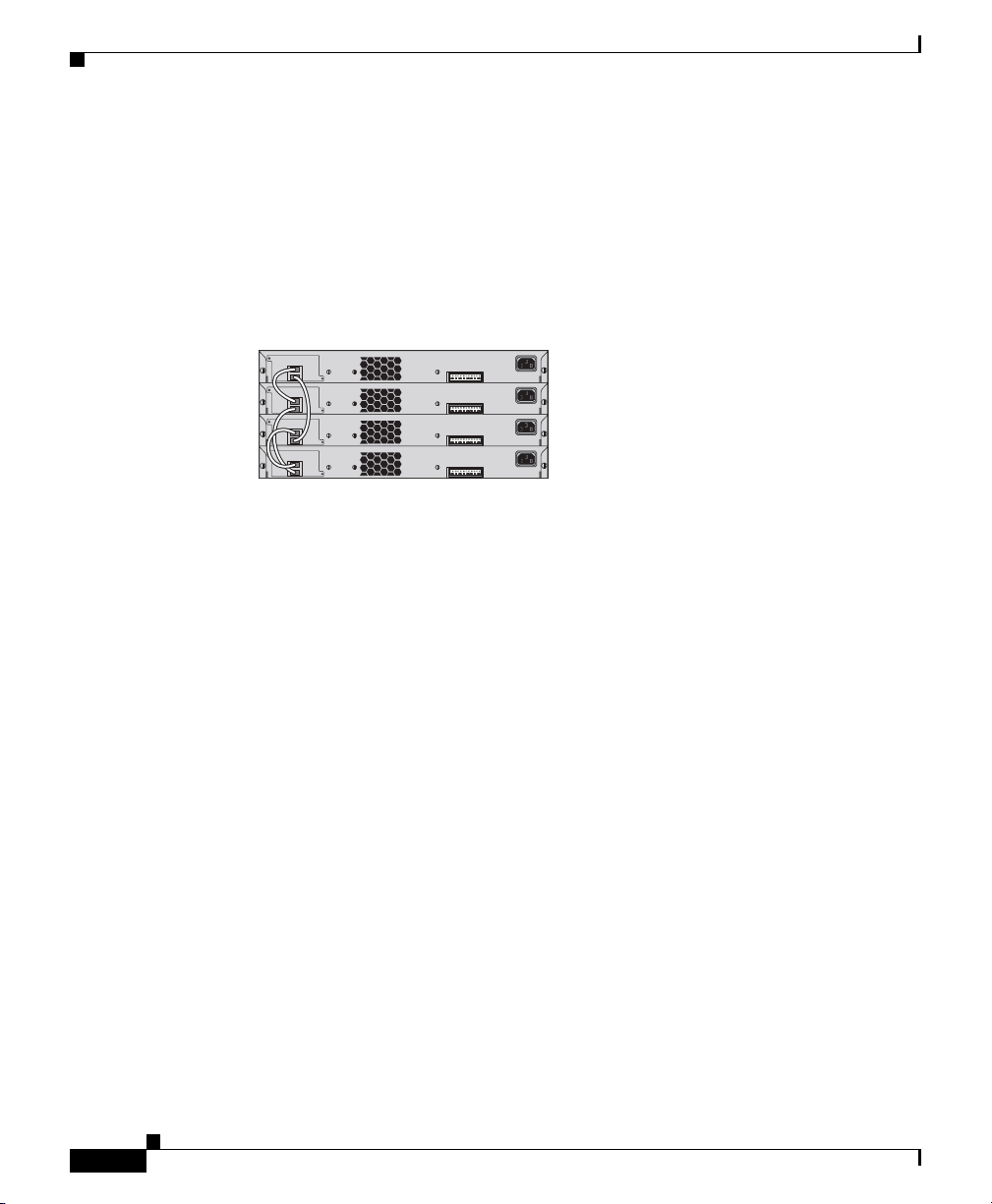
Cabling Guidelines
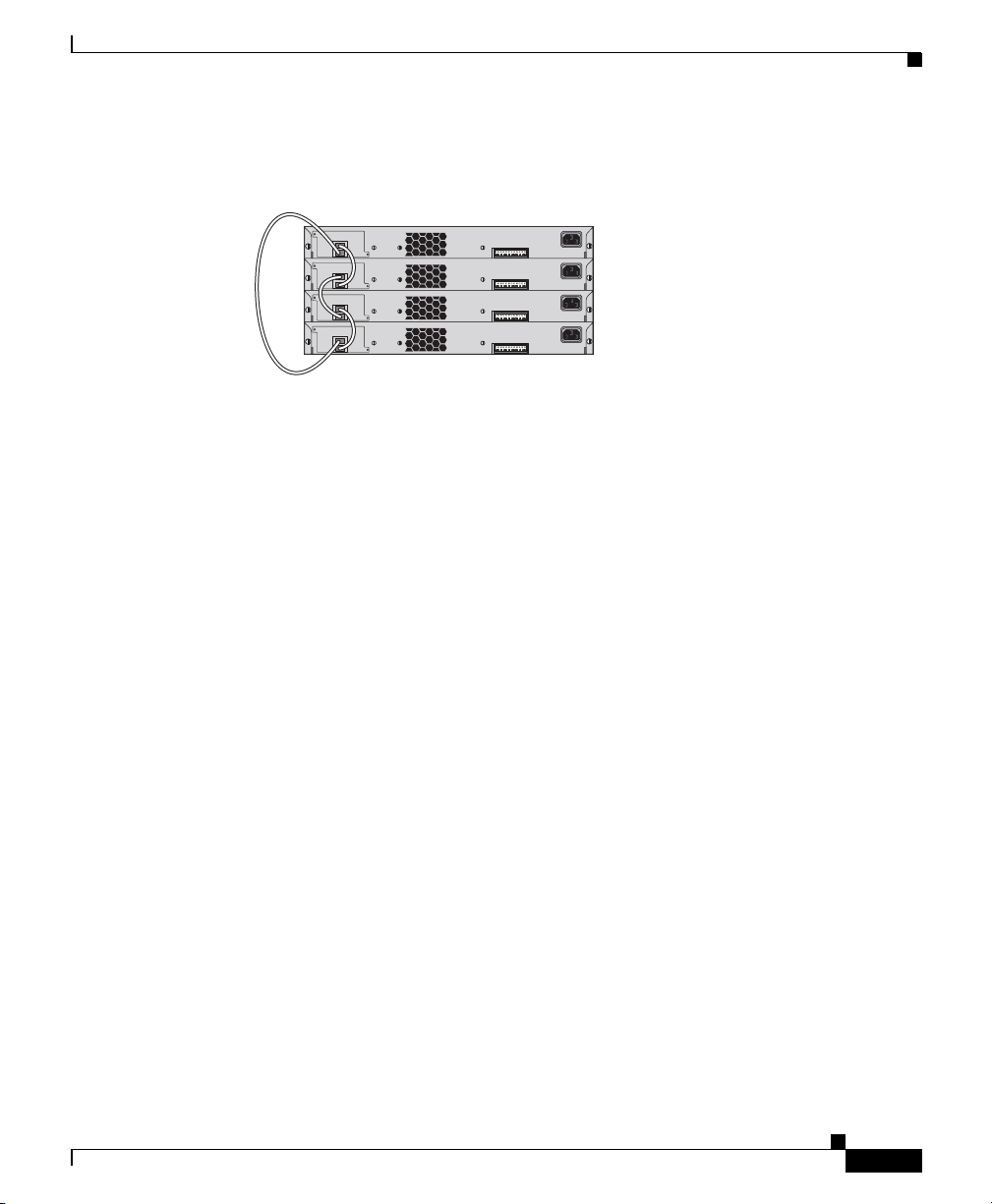
These illustrations show the recommended switch stack configurations with
redundant stack cabling connections for optimized stack bandwidth. For more
configuration examples, see the hardware installation guide on Cisco.com.
This is an example of a redundant stack cable connection using the 0.5-meter
FlexStack cable.
Catalyst 2960-S Switch Getting Started Guide
16
Catalyst 2960-S Switch Getting Started Guide
OL-19793-02
Page 17
Catalyst 2960-S Switch Getting Started Guide
This is an example of a redundant stack cable connection using both the 0.5- and
3-meter FlexStack cables.
Powering Guidelines
Consider these guidelines before you power the switches in a stack:
• If you want a particular switch to become the stack master, power on that
switch first. This switch becomes the stack master and remains the stack
master until a master reelection is required. After 2 minutes, power on the
remaining switches in the stack.
• Power off a switch before you add it to or remove it from an existing switch
stack.
For more information on stack master elections, see the “Managing Switch
Stacks” chapter in the switch software configuration guide on Cisco.com.
206230
OL-19793-02
Catalyst 2960-S Switch Getting Started Guide
17
Page 18

Rack-Mounting
This section covers basic 19-inch rack-mounting and switch port connections. As
an example, all the illustrations show the Catalyst 2960S-48FPD-L switch. You
can install and connect the other Catalyst 2960-S switches as shown in these
illustrations. For alternate mounting procedures, such as installing the switch in a
24-inch rack or on a wall, and for additional cabling information, see the hardware
installation guide on Cisco.com.
Required Tools
You need to supply a number-2 Phillips screwdriver to rack-mount the switch.
Before You Begin
Before installing the switch, verify that these guidelines are met:
• Clearance to the front panels is sufficient so that the LEDs can be easily read.
• Access to the switch rear panel to connect the optional Cisco Redundant
Power Supply (RPS) 2300 or to stack the switches. If you do not have access
to the rear panel, you should cable the switches before you rack-mount them.
Catalyst 2960-S Switch Getting Started Guide
18
• AC power cord reaches from the AC power outlet to the connector on the
switch rear panel.
• Cabling is away from sources of electrical noise, such as radios, power lines,
and fluorescent lighting fixtures. Make sure the cabling is safely away from
other devices that might damage the cables.
• Airflow around the switch and through the vents is unrestricted.
• Temperature around the unit does not exceed 113°F (45°C). If the switch is
installed in a closed or multirack assembly, the temperature around it might
be greater than normal room temperature.
• Humidity around the switch does not exceed 85 percent.
• Altitude at the installation site is not greater than 10,000 feet.
Catalyst 2960-S Switch Getting Started Guide
OL-19793-02
Page 19
Catalyst 2960-S Switch Getting Started Guide
• For 10/100 or 10/100/1000 fixed ports, cable lengths from the switch to
connected devices can be up to 328 feet (100 meters).
• For cable lengths for small form-factor pluggable (SFP)-module connections,
see the hardware installation guide on Cisco.com and the documentation that
shipped with the module.
Installation Warning Statements
This section includes the basic installation warning statements. Translations of
these warning statements appear in the Regulatory Compliance and Safety
Information for the Catalyst 2960 and
2960-S Switches document on Cisco.com.
Warning
Warning
Warning
To prevent bodily injury when mounting or servicing this unit in a rack, you must
take special precautions to ensure that the system remains stable. The
following guidelines are provided to ensure your safety:
This unit should be mounted at the bottom of the rack if it is the only unit in the
rack.
When mounting this unit in a partially filled rack, load the rack from the bottom
to the top with the heaviest component at the bottom of the rack.
If the rack is provided with stabilizing devices, install the stabilizers before
mounting or servicing the unit in the rack.
Class 1 laser product.
This equipment must be grounded. Never defeat the ground conductor or
operate the equipment in the absence of a suitably installed ground conductor.
Contact the appropriate electrical inspection authority or an electrician if you
are uncertain that suitable grounding is available.
Statement 1008
Statement 1006
Statement 1024
OL-19793-02
Catalyst 2960-S Switch Getting Started Guide
19
Page 20
Catalyst 2960-S Switch Getting Started Guide
252587
39X
38X
47X
48X
1
2
Catalyst 2960-S
Series
PoE+ 10G
Warning
To prevent the system from overheating, do not operate it in an area that
exceeds the maximum recommended ambient temperature of:
Warning
<113°F (45°C).
To prevent airflow restriction, allow clearance around the ventilation openings
to be at least:
3 inches (7.6 cm).
Statement 1047
Statement 1076
Before Attaching Brackets
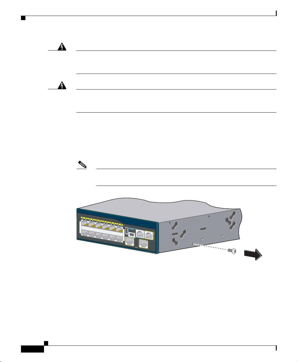
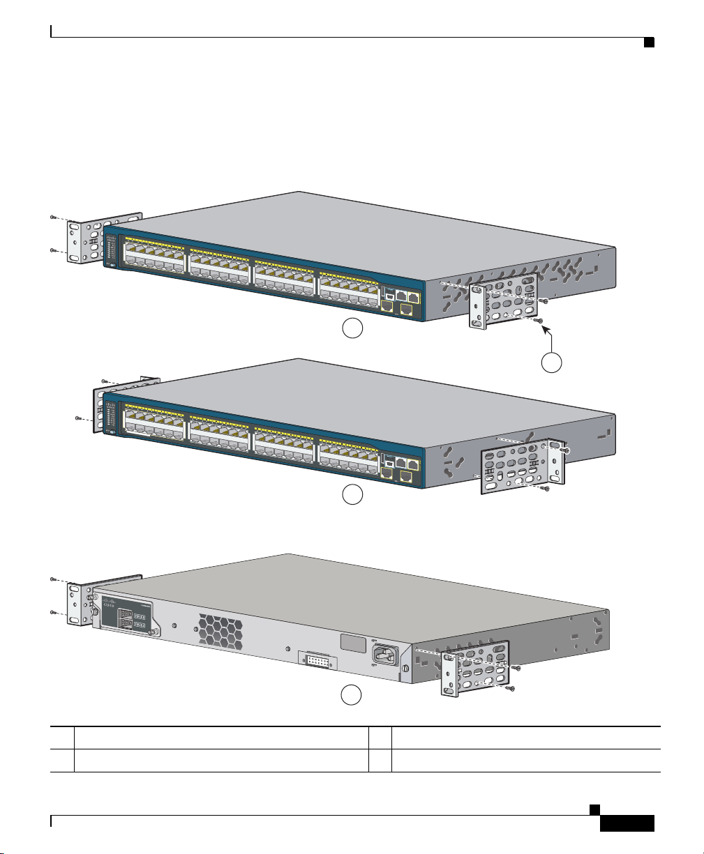
To install the switch in a rack, you must first remove the screws from the switch
chassis so that the mounting brackets can be attached.
Note You do not need to remove the screws for attaching the brackets in the
rear-mounting position.
20
Catalyst 2960-S Switch Getting Started Guide
OL-19793-02
Page 21
Catalyst 2960-S Switch Getting Started Guide
POWER
OVER
ETHERNET 740W
11X
2X
1X
11X
14X
12X
13X
23X
24X
25X
26X
37X
39X
36X
38X
47X
48X
1
2
Catalyst 2960-S
Series
PoE+ 10G
Catalyst 2960-S
Series
PoE+ 10G
RATING
100-240~
12-6A, 50-60Hz
11X
2X
1X
11X
14X
12X
13X
23X
24X
25X
26X
37X
39X
36X
38X
47X
48X
1
2
POWER
OVER
ETHERNET 740W
Catalyst 2960-S
Series
PoE+ 10G
206599
2
1
3
4
Attaching the Brackets
Use four Phillips flat-head screws to attach the long side of the brackets to
Catalyst 2960-S switches in one of three mounting positions.
1 Front-mounting position 3 Mid-mounting position
2 Number-8 Phillips flat-head screws (48-0655-01) 4 Rear-mounting position
Catalyst 2960-S Switch Getting Started Guide
OL-19793-02
21
Page 22
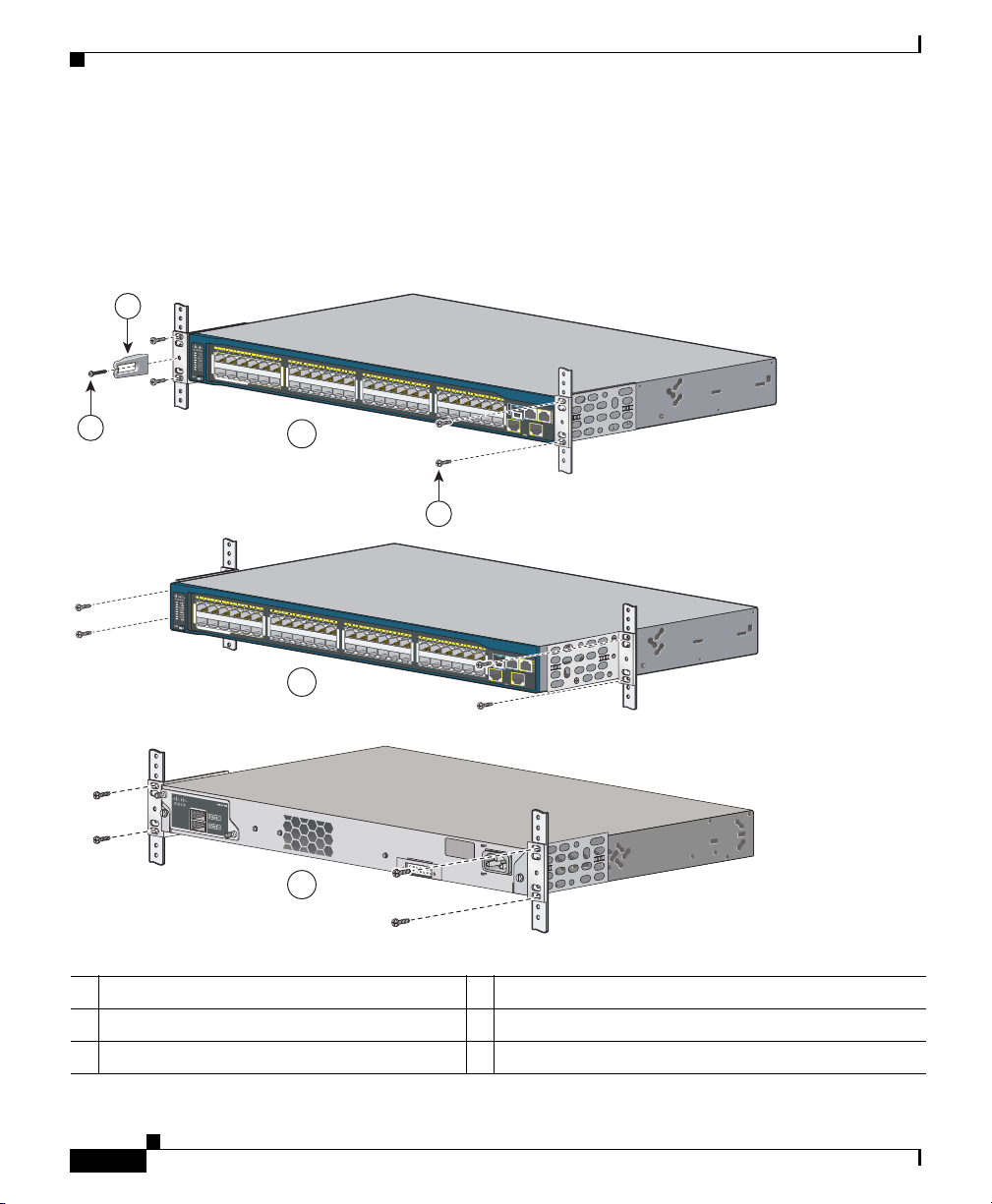
Rack-Mount the Switch
Use the four number-12 Phillips machine screws to attach the brackets to the rack.
Use the black Phillips machine screw to attach the cable guide to the left or right
bracket.
.
1
Catalyst 2960-S Switch Getting Started Guide
1X
2X
POWER
2
11X
11X
ETHERNET 740W
13X
12X
14X
OVER
23X
25X
24X
26X
3
36X
38X
37X
39X
Catalyst 2960-S
47X
48X
1
Series
PoE+ 10G
2
4
1X
2X
POWER
11X
11X
ETHERNET 740W
13X
12X
14X
OVER
23X
25X
24X
26X
5
36X
38X
37X
39X
RATING
100-240~
12-6A, 50-60Hz
Catalyst 2960-S
47X
48X
1
Series
PoE+ 10G
2
6
206600
1 Cable guide 4 Number-12 Phillips pan-head screws (48-0523-01)
2 Black Phillips machine screw (48-0654-01) 5 Mid-mounting position
3 Front-mounting position 6 Rear-mounting position
Catalyst 2960-S Switch Getting Started Guide
22
OL-19793-02
Page 23
Catalyst 2960-S Switch Getting Started Guide
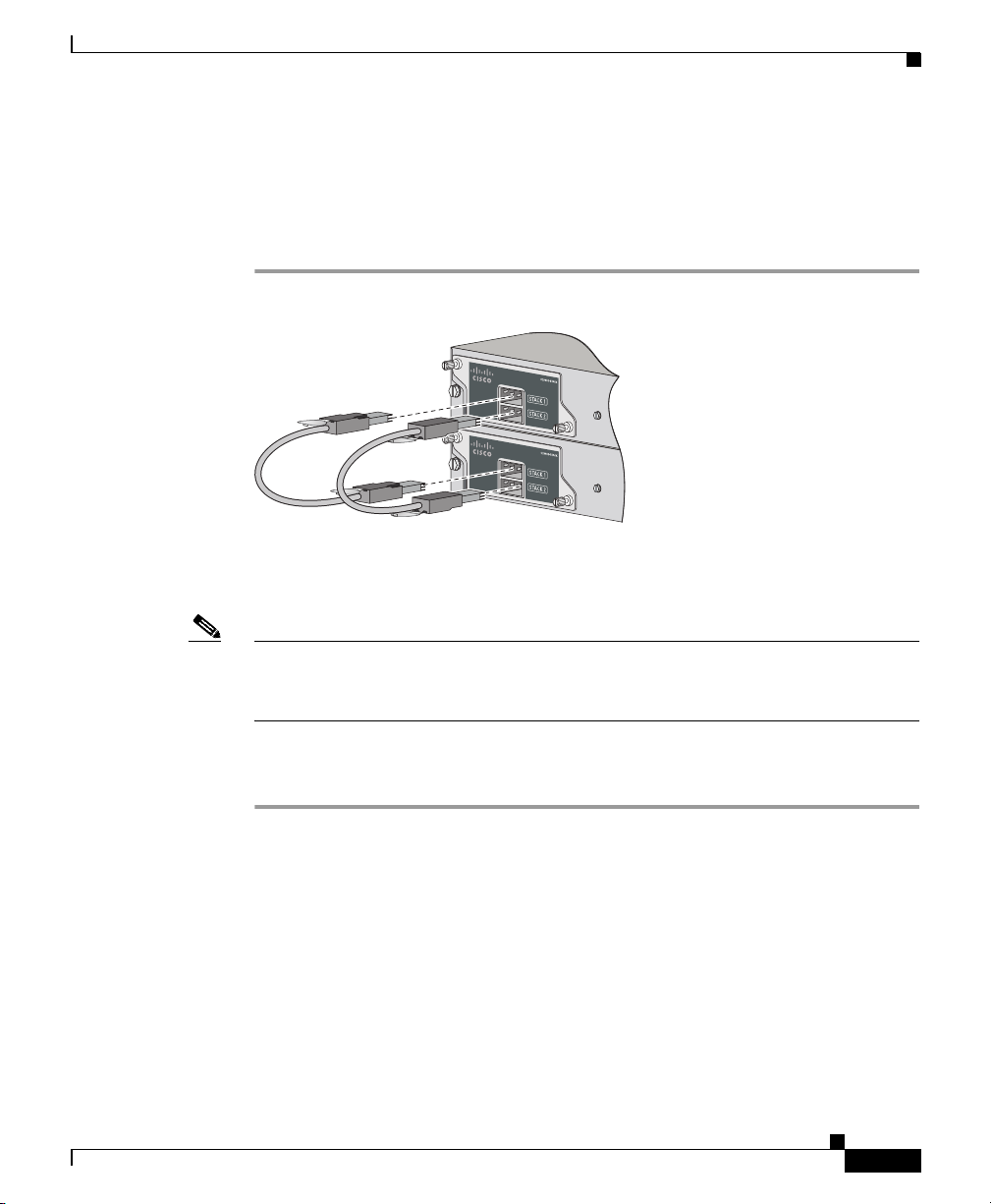
Connecting the FlexStack Cables
Always use a Cisco-approved FlexStack cable to connect the switches. Connect
only Catalyst 2960-S switches in a switch stack.
Step 1 Remove the dust covers from the FlexStack cables, and store them for future use.
Step 2 Insert one end of the FlexStack cable into the stack port of the first switch. Insert
the other end of the cable into the stack port on the other switch.
206235
OL-19793-02
Note When you connect the FlexStack cable into the STACK 1 port, the tab should be
above the connector. When you connect the FlexStack cable into the STACK 2
port, you should invert the cable so that the tab is below the connector.
Step 3 Replace the dust covers when you remove the FlexStack cables from the
connectors.
Removing and installing the FlexStack cable can shorten its useful life. Do not
remove and insert the cable more often than is absolutely necessary.
Catalyst 2960-S Switch Getting Started Guide
23
Page 24
11X
14X12X
1X
2X
11X
POWER
OVER
ETHERNET 740W
206236
Connecting to the Switch Ports
This section describes how to connect to the fixed switch ports and to the SFP
module ports.
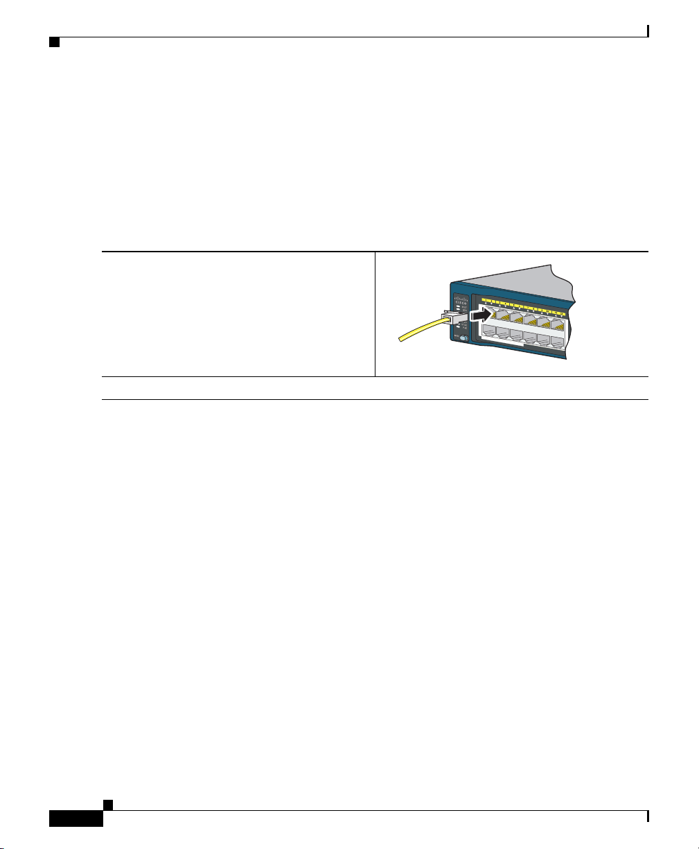
Connect to the 10/100 or 10/100/1000 Ports
Catalyst 2960-S Switch Getting Started Guide
Step 1
Step 2
When you connect to servers, workstations,
IP phones, wireless access points, and routers,
insert a straight-through, twisted four-pair,
Category 5 cable in a switch 10/100 or
10/100/1000 port. Use a crossover, twisted
four-pair, Category 5 cable when you connect
to other switches, hubs, or repeaters.
Insert the other cable end into an RJ-45 port on the other device.
The fixed ports on the Catalyst 2960-S Power over Ethernet Plus (PoE+) switches
provide:
• PoE+ support for IEEE 802.3at-compliant powered devices
• PoE support for IEEE 802.3af-compliant powered devices
• Support for Cisco enhanced PoE (ePoE)
They also provide Cisco prestandard PoE support for Cisco IP phones and Cisco
Aironet Access Points. See the switch hardware guide for information on PoE
budgeting.
By default, a Catalyst 2960-S switch PoE port automatically provides power when
a compliant device is connected, including ePoE, PoE, and PoE+. For information
about configuring and monitoring PoE and PoE+ ports, see the switch software
configuration guide.
24
Catalyst 2960-S Switch Getting Started Guide
OL-19793-02
Page 25
Catalyst 2960-S Switch Getting Started Guide
47X
48X
1
2
Catalyst 2960-S
Series
PoE+ 10G
206237
47X
48X
1
2
Catalyst 2960-S
Series
PoE+ 10G
Note The automatic medium-dependent interface crossover (auto-MDIX) feature is
enabled by default. The switch detects the required cable type for copper Ethernet
connections and configures the interfaces accordingly. Therefore, you can use
either a crossover or a straight-through cable for connections to a copper 10/100
or 10/100/1000 module port on the switch, regardless of the type of device on the
other end of the connection.
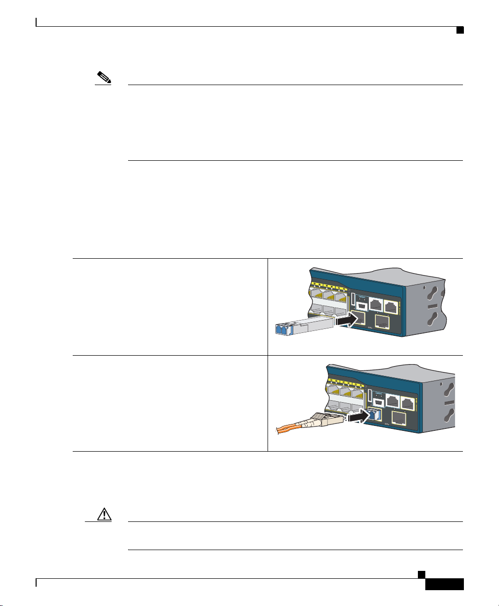
Install the SFP or SFP+ Modules
Some Catalyst 2960-S switches have SFP module slots and others have SFP+
module slots. The SFP slots support only the SFP modules. The SFP+ slots
support both SFP and SFP+ modules.
Step 1
Step 2
OL-19793-02
Grasp the module on the sides, and insert it
into the switch slot until you feel the
connector snap into place.
Insert an appropriate cable into the module
port. Insert the other cable end into the other
device.
For a list of supported modules, see the release notes on Cisco.com. For detailed
instructions on installing, removing, and connecting to SFP modules, see the
documentation that came with the SFP module.
Caution Removing and installing an SFP module can shorten its useful life. Do not remove
and insert SFP modules more often than is absolutely necessary.
Catalyst 2960-S Switch Getting Started Guide
25
Page 26

Verify Port Connectivity
After you connect the switch port and another device, the port LED turns amber
while the switch establishes a link. This process takes about 30 seconds, and then
the LED turns green. If the LED turns off, the target device might not be turned
on, there might be a cable problem, or there might be a problem with the adapter
installed in the target device. See the
for information about online assistance.
In Case of Difficulty
If you experience difficulty, help is available in this section and also on
Cisco.com. This section includes Express Setup troubleshooting, how to reset the
switch, how to access help online, and where to find more information.
Troubleshooting Express Setup
Catalyst 2960-S Switch Getting Started Guide
“In Case of Difficulty” section on page 26
26
If Express Setup does not run, or if the Express Setup page does not appear in your
browser:
Did you verify that POST ran
successfully before starting
Express Setup?
Did you press the Mode button
while the switch was still running
POST?
Catalyst 2960-S Switch Getting Started Guide
If not, make sure that only the SYST and
STAT LEDs are green before you press the
Mode button to enter the Express Setup
mode.
POST errors are usually fatal. Contact your
Cisco technical support representative if your
switch fails POST.
If yes, wait until POST completes. Power
cycle the switch. Wait until POST completes.
Confirm that the SYST and STAT LEDs are
green. Press the Mode button to enter
Express Setup mode.
OL-19793-02
Page 27

Catalyst 2960-S Switch Getting Started Guide
Did you try to continue without
confirming that the switch was in
Express Setup mode?
Does your PC have a static IP
address?
Did you connect a crossover
cable instead of a
straight-through Ethernet cable
between a switch port and the
Ethernet port of the PC?
Did you connect the Ethernet
cable to the console port instead
of to a 10/100 or 10/100/1000
Ethernet port on the switch?
Verify that all LEDs above the Mode button
are green. (The RPS LED is off.) If
necessary, press the Mode button to enter
Express Setup mode.
If yes, before connecting to the switch,
change your PC settings to temporarily use
DHCP.
If yes, connect a straight-through cable to an
Ethernet port on the switch and the PC. Wait
30 seconds before you enter 10.0.0.1 in the
browser.
If yes, disconnect the cable from the console
port. Then connect the cable to an Ethernet
port on the switch and the PC. Wait 30
seconds before you enter 10.0.0.1 in the
browser.
Note The console port is outlined in blue,
and the Ethernet port is outlined in
yellow.
OL-19793-02
Did you wait 30 seconds after you
connected the switch and the PC
before you entered the IP address
in your browser?
Did you enter the wrong address
in the browser, or is there an error
message?
If not, wait 30 seconds, re-enter 10.0.0.1 in
the browser, and press Enter.
If yes, re-enter 10.0.0.1 in the browser, and
press Enter.
Catalyst 2960-S Switch Getting Started Guide
27
Page 28

Resetting the Switch
Follow these steps to return your switch to the factory default settings. These are
reasons why you might want to reset the switch:
• You installed the switch in your network and cannot connect to it because you
assigned the wrong IP address.
• You want to clear all configurations from the switch and assign a new IP
address.
• You want to reset the password on the switch.
Caution Resetting the switch deletes the configuration and reboots the switch.
To reset the switch:
Press and hold the Mode button. The switch LEDs begin blinking after about
3 seconds. Continue holding down the Mode button. The LEDs stop blinking after
7 more seconds, and then the switch reboots.
The switch now behaves like an unconfigured switch. You can enter the switch IP
information by using Express Setup as described in the
section on page 4.
Catalyst 2960-S Switch Getting Started Guide
“Running Express Setup”
Accessing Help Online
First look for a solution to your problem in the troubleshooting section of the
switch hardware installation guide or the switch software configuration guide on
Cisco.com. You can also access the Cisco Technical Support and Documentation
website for a list of known hardware problems and extensive troubleshooting
documentation.
Catalyst 2960-S Switch Getting Started Guide
28
OL-19793-02
Page 29

Catalyst 2960-S Switch Getting Started Guide
For More Information
For more information about the switch, see these documents on Cisco.com:
• Catalyst 2960-S Switch Hardware Installation Guide
• Regulatory Compliance and Safety Information for the Catalyst 2960
and 2960-S Switches
• Release Notes for the Catalyst 2960-S Switch
• Catalyst 2960 and 2960-S Switch Software Configuration Guide
• Catalyst 2960 and 2960-S Switch Command Reference
• Catalyst 3750, 3560, 2975, 2960, and 2960-S Switch System Message Guide
• Device Manager online help (available on the switch)
• Cisco Small Form-Factor Pluggable Modules Installation Notes
Obtaining Documentation and Submitting a Service Request
For information on obtaining documentation, submitting a service request, and
gathering additional information, see the monthly What’s
Documentation, which also lists all new and revised Cisco
documentation, at:
http://www.cisco.com/en/US/docs/general/whatsnew/whatsnew.html
Subscribe to the What’s New in Cisco Product Documentation as a Really Simple
Syndication (RSS) feed and set content to be delivered directly to your desktop using
a reader application. The RSS feeds are a free service and Cisco currently supports
RSS version 2.0.
Cisco and the Cisco logo are trademarks or registered trademarks of Cisco and/or its affiliates in the U.S. and other
countries. To view a list of Cisco
trademarks mentioned are the property of their respective owners. The use of the word partner does not imply a
partnership relationship between Cisco and any other company. (1110R)
Any Internet Protocol (IP) addresses used in this document are not intended to be actual addresses. Any examples,
command display output, and figures included in the document are shown for illustrative purposes only. Any use of
actual IP addresses in illustrative content is unintentional and coincidental.
© 2010-2012 Cisco Systems, Inc. All rights reserved.
OL-19793-02
New in Cisco Product
technical
trademarks, go to this URL: www.cisco.com/go/trademarks. Third-party
Catalyst 2960-S Switch Getting Started Guide
29
Page 30

Catalyst 2960-S Switch Getting Started Guide
30
Catalyst 2960-S Switch Getting Started Guide
OL-19793-02
 Loading...