

Page 1

Cisco CRS Carrier Routing System
4-Slot
Line Card Chassis
Installation Guide
July 2011
Americas Headquarters
Cisco Systems, Inc.
170 West Tasman Drive
San Jose, CA 95134-1706
USA
http://www.cisco.com
Tel: 408 526-4000
800 553-NETS (6387)
Fax: 408 527-0883
Text Part Number: OL-10971-10
Page 2

THE SPECIFICATIONS AND INFORMATION REGARDING THE PRODUCTS IN THIS MANUAL ARE SUBJECT TO CHANGE WITHOUT NOTICE. ALL
STATEMENTS, INFORMATION, AND RECOMMENDATIONS IN THIS MANUAL ARE BELIEVED TO BE ACCURATE BUT ARE PRESENTED WITHOUT
WARRANTY OF ANY KIND, EXPRESS OR IMPLIED. USERS MUST TAKE FULL RESPONSIBILITY FOR THEIR APPLICATION OF ANY PRODUCTS.
THE SOFTWARE LICENSE AND LIMITED WARRANTY FOR THE ACCOMPANYING PRODUCT ARE SET FORTH IN THE INFORMATION PACKET THAT
SHIPPED WITH THE PRODUCT AND ARE INCORPORATED HEREIN BY THIS REFERENCE. IF YOU ARE UNABLE TO LOCATE THE SOFTWARE LICENSE
OR LIMITED WARRANTY, CONTACT YOUR CISCO REPRESENTATIVE FOR A COPY.
The following information is for FCC compliance of Class A devices: This equipment has been tested and found to comply with the limits for a Class A digital device, pursuant
to part 15 of the FCC rules. These limits are designed to provide reasonable protection against harmful interference when the equipment is operated in a commercial
environment. This equipment generates, uses, and can radiate radio-frequency energy and, if not installed and used in accordance with the instruction manual, may cause
harmful interference to radio communications. Operation of this equipment in a residential area is likely to cause harmful interference, in which case users will be required
to correct the interference at their own expense.
The following information is for FCC compliance of Class B devices: The equipment described in this manual generates and may radiate radio-frequency energy. If it is not
installed in accordance with Cisco’s installation instructions, it may cause interference with radio and television reception. This equipment has been tested and found to
comply with the limits for a Class B digital device in accordance with the specifications in part 15 of the FCC rules. These specifications are designed to provide reasonable
protection against such interference in a residential installation. However, there is no guarantee that interference will not occur in a particular installation.
Modifying the equipment without Cisco’s written authorization may result in the equipment no longer complying with FCC requirements for Class A or Class B digital
devices. In that event, your right to use the equipment may be limited by FCC regulations, and you may be required to correct any interference to radio or television
communications at your own expense.
You can determine whether your equipment is causing interference by turning it off. If the interference stops, it was probably caused by the Cisco equipment or one of its
peripheral devices. If the equipment causes interference to radio or television reception, try to correct the interference by using one or more of the following measures:
• Turn the television or radio antenna until the interference stops.
• Move the equipment to one side or the other of the television or radio.
• Move the equipment farther away from the television or radio.
• Plug the equipment into an outlet that is on a different circuit from the television or radio. (That is, make certain the equipment and the television or radio are on circuits
controlled by different circuit breakers or fuses.)
Modifications to this product not authorized by Cisco Systems, Inc. could void the FCC approval and negate your authority to operate the product.
The Cisco implementation of TCP header compression is an adaptation of a program developed by the University of California, Berkeley (UCB) as part of UCB’s public
domain version of the UNIX operating system. All rights reserved. Copyright © 1981, Regents of the University of California.
NOTWITHSTANDING ANY OTHER WARRANTY HEREIN, ALL DOCUMENT FILES AND SOFTWARE OF THESE SUPPLIERS ARE PROVIDED “AS IS” WITH
ALL FAULTS. CISCO AND THE ABOVE-NAMED SUPPLIERS DISCLAIM ALL WARRANTIES, EXPRESSED OR IMPLIED, INCLUDING, WITHOUT
LIMITATION, THOSE OF MERCHANTABILITY, FITNESS FOR A PARTICULAR PURPOSE AND NONINFRINGEMENT OR ARISING FROM A COURSE OF
DEALING, USAGE, OR TRADE PRACTICE.
IN NO EVENT SHALL CISCO OR ITS SUPPLIERS BE LIABLE FOR ANY INDIRECT, SPECIAL, CONSEQUENTIAL, OR INCIDENTAL DAMAGES, INCLUDING,
WITHOUT LIMITATION, LOST PROFITS OR LOSS OR DAMAGE TO DATA ARISING OUT OF THE USE OR INABILITY TO USE THIS MANUAL, EVEN IF CISCO
OR ITS SUPPLIERS HAVE BEEN ADVISED OF THE POSSIBILITY OF SUCH DAMAGES.
Cisco and the Cisco logo are trademarks or registered trademarks of Cisco and/or its affiliates in the U.S. and other countries. To view a list of Cisco trademarks, go to this
URL: www.cisco.com/go/trademarks. Third-party trademarks mentioned are the property of their respective owners. The use of the word partner does not imply a partnership
relationship between Cisco and any other company. (1110R)
Cisco CRS Carrier Routing System 4-Slot Line Card Chassis Installation Guide
© 2011 Cisco Systems, Inc. All rights reserved.
Page 3

CONTENTS
Preface vii
Objective vii
Audience vii
Document Organization vii
Document Conventions viii
Related Documentation ix
Changes to This Document x
Obtaining Documentation and Submitting a Service Request xi
CHAPTER
CHAPTER
1 Overview 1-1
Chassis Overview 1-1
Chassis Components 1-2
Chassis Slot Numbers 1-5
Chassis Cable Management 1-7
Chassis Cooling System 1-7
Chassis Power System 1-8
Safety Guidelines 1-8
Preventing Electrostatic Discharge 1-9
Recommended Chassis Installation Task Sequence 1-10
CRS Hardware Compatibility 1-10
2 Installing and Removing Power Components 2-1
About Installing and Removing the Power Components 2-1
Basic Chassis Power Recommendations 2-1
Supplemental Unit Bonding and Grounding Guidelines 2-2
AC Power Supply Cord Illustrations and Plug Types 2-4
Powering the Chassis Up or Down 2-6
DC Power Systems on the Cisco CRS 4-Slot Router 2-7
DC Power Shelf Guidelines 2-9
Input-Power-Present LEDs 2-11
DC Power Wire Characteristics 2-11
Installing a DC Power Shelf 2-14
OL-10971-10
Cisco CRS Carrier Routing System 4-Slot Line Card Chassis Installation Guide
iii
Page 4

Contents
Removing a DC Power Shelf 2-20
Installing an AC Power Shelf 2-24
Removing an AC Power Shelf 2-26
Installing a Power Supply 2-28
Removing a Power Supply 2-30
CHAPTER
CHAPTER
3 Installing and Removing Air Circulation Components 3-1
About Line Card Chassis Airflow 3-1
How to Install or Remove Air Circulation Components 3-3
Installing a Fan Tray 3-4
Removing a Fan Tray 3-5
Installing the Chassis Air Filter 3-7
Removing the Chassis Air Filter 3-9
Installing a Power Tray Air Filter 3-10
Removing a Power Tray Air Filter 3-12
4 Installing and Removing SFCs, RPs, MSCs, FPs, LSPs, PLIMs, and Associated Components 4-1
About Installing and Removing Cards and Associated Components 4-1
Guidelines for Card Installation and Removal 4-2
PCMCIA Cards 4-4
Small Form-Factor Pluggable (SFP) Modules 4-4
Cable Management Brackets 4-5
How to Remove or Install an Impedance Carrier 4-5
Removing an Impedance Carrier 4-10
Installing an Impedance Carrier 4-10
How to Remove or Install a Card Slide-Assistance Arm (Handle) 4-11
Removing a Card Slide-Assistance Arm 4-12
Installing a Card Slide-Assistance Arm 4-13
How to Install or Remove a Pillow Block 4-14
Installing a Pillow Block 4-15
Removing a Pillow Block 4-16
How to Install or Remove a Switch Fabric Card 4-18
Switch Fabric Card Location and Slot Numbers 4-18
Installing a Switch Fabric Card 4-18
Removing a Switch Fabric Card 4-22
Verifying the Installation of a Switch Fabric Card 4-23
How to Install or Remove a Route Processor Card 4-24
Location and Slot Numbers for the RPs, MSCs, FPs, LSPs, and PLIMs 4-25
Cisco CRS Carrier Routing System 4-Slot Line Card Chassis Installation Guide
iv
OL-10971-10
Page 5

Installing an RP or PRP Card 4-26
Removing an RP or PRP Card 4-29
Verifying the Installation of an RP or PRP Card 4-30
How to Install or Remove an MSC, FP, or LSP 4-32
Installing an MSC, FP, or LSP 4-33
Removing an MSC, FP, or LSP 4-37
Verifying the Installation of an MSC, FP, or LSP 4-40
How to Install or Remove a Physical Layer Interface Module 4-41
Installing a PLIM 4-41
Removing a PLIM 4-47
Verifying the Installation of a PLIM 4-49
How to Install or Remove a PCMCIA Card 4-50
Installing a PCMCIA Card 4-50
Removing an RP PCMCIA Card 4-51
How to Install or Remove a Small Form-Factor Pluggable (SFP) Module 4-52
Installing a Bale-Clasp SFP Module 4-53
Removing a Bale-Clasp SFP Module 4-54
Contents
CHAPTER
APPENDIX
I
NDEX
5 Installing and Removing the Doors and Grille 5-1
Overview of the Exterior Components 5-1
Installing the Inlet Grille 5-1
Removing the Inlet Grille 5-3
Installing the Doors 5-4
Opening the Doors 5-7
Removing the Doors 5-8
A Cisco CRS 4-Slot Line Card Chassis System Specifications A-1
Compliance and Safety Reference A-1
Cisco CRS 4-Slot Line Card Chassis Specifications A-1
Environmental Specifications A-3
OL-10971-10
Cisco CRS Carrier Routing System 4-Slot Line Card Chassis Installation Guide
v
Page 6

Contents
Cisco CRS Carrier Routing System 4-Slot Line Card Chassis Installation Guide
vi
OL-10971-10
Page 7
Preface
This preface explains the objectives, intended audience, and organization of Cisco CRS Carrier Routing
System 4-Slot Line Card Chassis Installation Guide and describes the conventions that convey
instructions and other information.
The preface contains the following sections:
• Objective, page vii
• Audience, page vii
• Document Organization, page vii
• Document Conventions, page viii
• Related Documentation, page ix
• Changes to This Document, page x
• Obtaining Documentation and Submitting a Service Request, page xi
Objective
This installation guide describes how to install components into and remove them from a Cisco CRS
4-slot line card chassis. This installation guide does not provide background information and basic
theory-of-operation for anyone wanting to understand the Cisco CRS Carrier Routing System.
Audience
This guide is intended for Cisco CRS 4-slot line card chassis installers and Cisco installation partners
who are responsible for installing the line card chassis components. The chassis installers are expected
to have installed networking hardware in the past. No additional knowledge of routing or the
Cisco IOS XR software is assumed.
Document Organization
This guide contains the following chapters and appendixes:
OL-10971-10
Cisco CRS Carrier Routing System 4-Slot Line Card Chassis Installation Guide
vii
Page 8

Preface
• Chapter 1, “Overview,” provides an introduction to the various line card chassis systems and
components. This chapter also provides the recommended sequence of tasks for installing all the
major components of the Cisco CRS 4-slot line card chassis.
• Chapter 2, “Installing and Removing Power Components,” details how to bring power to and install
power components in the line card chassis, including the AC and DC power shelves power supplies,
and alarm module.
• Chapter 3, “Installing and Removing Air Circulation Components,” describes how to install the fan
trays and air filters.
• Chapter 4, “Installing and Removing SFCs, RPs, MSCs, FPs, LSPs, PLIMs, and Associated
Components,” provides instructions on how to install various cards, including PLIMs, switch fabric
cards, and modular services cards.
• Chapter 5, “Installing and Removing the Doors and Grille,” documents how to install and remove
the optional exterior components, the front doors and grille.
• Appendix A, “Cisco CRS 4-Slot Line Card Chassis System Specifications,” lists the technical
specifications for the Cisco CRS 4-slot line card chassis.
Document Conventions
This guide uses the convention where the symbol ^ represents the key labeled Control. For example, the
key combination ^z means hold down the Control key while you press the z key.
Command descriptions use these conventions:
• Examples that contain system prompts denote interactive sessions, indicating the commands that
you should enter at the prompt. The system prompt indicates the current level of the EXEC
command interpreter. For example, the prompt
level, and the prompt
privileged level usually requires a password. Refer to the related software configuration and
reference documentation listed in “Related Documentation” for additional information.
• Commands and keywords are in boldface font.
• Arguments for which you supply values are in italic font.
• Elements in square brackets ([ ]) are optional.
• Alternative but required keywords are grouped in braces ({}) and separated by vertical bars (|).
Examples use these conventions:
• Terminal sessions and sample console screen displays are in screen font.
• Information you enter is in boldface screen font.
• Nonprinting characters, such as passwords, are in angle brackets (< >).
• Default responses to system prompts are in square brackets ([]).
• Exclamation points (!) at the beginning of a line indicate a comment line.
router> indicates that you should be at the user
router# indicates that you should be at the privileged level. Access to the
Note Means reader take note. Notes contain helpful suggestions or references to materials not contained in
this manual.
Cisco CRS Carrier Routing System 4-Slot Line Card Chassis Installation Guide
viii
OL-10971-10
Page 9

Preface
Timesaver Means the described action saves time. You can save time by performing the action described in the
paragraph.
Caution Means reader be careful. You are capable of doing something that might result in equipment damage or
loss of data.
Warning
This warning symbol means danger. You are in a situation that could cause bodily injury. Before you
work on any equipment, be aware of the hazards involved with electrical circuitry and be familiar
with standard practices for preventing accidents. To see translations of the warnings that appear in
this publication, refer to the Regulatory Compliance and Safety Information document that
accompanied this device.
Related Documentation
For complete planning, installation, and configuration information, refer to the following documents:
• Cisco CRS Carrier Routing System 4-Slot Line Card Chassis System Description
• Cisco CRS Carrier Routing System 4-Slot Line Card Chassis Site Planning Guide
• Cisco CRS Carrier Routing System 4-Slot Line Card Chassis Unpacking, Moving, and Securing
Guide
• Cisco CRS Carrier Routing System Ethernet Physical Layer Interface Module (PLIM) Installation
Note
• Cisco CRS Carrier Routing System Packet-over-SONET Physical Layer Interface Module (PLIM)
Installation Note
• Cisco CRS Fiber-Optic Cleaning Kit Quick Start Guide
• Cisco CRS Carrier Routing System Hardware Documentation Guide
• Cisco CRS Carrier Routing System Regulatory Compliance and Safety Information
For a complete listing of software documentation available, refer to About Cisco IOS XR Software
Documentation, available online at
Statement 1074
http://www.cisco.com/univercd/cc/td/doc/product/core/crs/xrabout.htm.
OL-10971-10
Cisco CRS Carrier Routing System 4-Slot Line Card Chassis Installation Guide
ix
Page 10

Changes to This Document
Table 1-1 lists the technical changes made to this document since it was first printed.
Table 1-1 Changes to This Document
Revision Date Change Summary
OL-10971-10 July 2011 Added information about new CRS-LSP Label Switch
OL-10971-09 April 2011 Added information about new CRS-4-PRP-6G and
OL-10971-08 October 2010 Added information about the new MSC-140G and FP-140
OL-10971-07 September 2009 Added additional information about plug styles for different
May 2008 Added new procedures on installing and removing a pillow
OL-10971-06 March 2008 Minor editorial changes.
OL-10971-05 August 2007 Technical updates were made to Chapter 2, “Installing and
OL-10971-04 June 2007 Added “Recommended Chassis Installation Task Sequence”
OL-10971-03 March 2007 Added “DC Power Systems on the Cisco CRS 4-Slot
OL-10971-02 November 2006 Added Chapter 5, “Installing and Removing the Doors and
OL-10971-01 November 2006 Initial release of the document
Preface
Processor (LSP) card to the following sections:
• Chapter 1, “Overview”
• Chapter 4, “Installing and Removing SFCs, RPs, MSCs,
FPs, LSPs, PLIMs, and Associated Components”
CRS-4-PRP-12G Performance Route Processor (PRP)
cards. Technical updates and minor editorial changes were
also made.
line cards, and QQ123-140G switch fabric cards. Minor
editorial changes were also made.
countries on the Cisco CRS Carrier Routing System 4-Slot
Line Card chassis. See Chapter 2, “AC Power Supply Cord
Illustrations and Plug Types”
block to Chapter 4, “Installing and Removing SFCs, RPs,
MSCs, FPs, LSPs, PLIMs, and Associated Components.”
Removing Power Components.”
in Chapter 1, “Overview,” and reorganized and revised
Chapter 4, “Installing and Removing SFCs, RPs, MSCs,
FPs, LSPs, PLIMs, and Associated Components.” Also
added “Removing a DC Power Shelf” in Chapter 2,
“Installing and Removing Power Components.”
Router”, “Installing a DC Power Shelf”, in Chapter 2,
“Installing and Removing Power Components.” Also
updated Appendix A, “Cisco CRS 4-Slot Line Card Chassis
System Specifications,” with DC power specifications and
other updates.
Grille.”
Cisco CRS Carrier Routing System 4-Slot Line Card Chassis Installation Guide
x
OL-10971-10
Page 11

Preface
Obtaining Documentation and Submitting a Service Request
For information on obtaining documentation, submitting a service request, and gathering additional
information, see the monthly What’s New in Cisco Product Documentation, which also lists all new and
revised Cisco technical documentation, at:
http://www.cisco.com/en/US/docs/general/whatsnew/whatsnew.html
Subscribe to the What’s New in Cisco Product Documentation as a Really Simple Syndication (RSS) feed
and set content to be delivered directly to your desktop using a reader application. The RSS feeds are a free
service and Cisco currently supports RSS version 2.0.
OL-10971-10
Cisco CRS Carrier Routing System 4-Slot Line Card Chassis Installation Guide
xi
Page 12

Preface
Cisco CRS Carrier Routing System 4-Slot Line Card Chassis Installation Guide
xii
OL-10971-10
Page 13

CHAP T ER
1
Overview
This chapter introduces the Cisco CRS Carrier Routing System 4-Slot Line Card Chassis at the highest
level. It contains illustrations of the front and back of the chassis, complete with callouts to each
hardware component. For details on each subsystem discussed in this chapter, see Cisco CRS Carrier
Routing System 4-Slot Line Card Chassis System Description. This chapter also provides the
recommended task sequence for installing the major components in the chassis.
This chapter presents the following topics:
• Chassis Overview, page 1-1
• Chassis Components, page 1-2
• Chassis Slot Numbers, page 1-5
• Chassis Cable Management, page 1-7
• Chassis Cooling System, page 1-7
• Chassis Power System, page 1-8
• Safety Guidelines, page 1-8
• Preventing Electrostatic Discharge, page 1-9
• Recommended Chassis Installation Task Sequence, page 1-10
• CRS Hardware Compatibility, page 1-10
Chassis Overview
The Cisco CRS 4-slot routing system can be installed in locations where the 16-slot or 8-slot systems
may not fit (for example, colocation facilities, data centers, and many Tier II and Tier III locations). The
routing system consists of a single rack-mounted chassis that contains the following system components:
• Switch fabric cards (SFCs) (up to four)
• Route processor (RP) cards (up to two) or performance route processor (PRP) cards (up to two)
• Up to four modular services cards (MSCs), forwarding processor (FP) cards, or label switch
processor (LSP) cards (also called line cards)
• Physical layer interface modules, or PLIMs, (up to four, one for each MSC or FP)
• A chassis midplane that connects line cards to their associated PLIMs and to the SFCs
The Cisco CRS 4-slot line card chassis has its own power and cooling subsystems. The power shelf (AC
or DC as ordered) is pre-installed in the chassis when you receive the routing system.
OL-10971-10
Cisco CRS Carrier Routing System 4-Slot Line Card Chassis Installation Guide
1-1
Page 14

Chassis Components
STATUS
STATUS
STATUS
STATUS
STATUS
STATUS
STATUS
STATUS
STATUS
STATUS
158366
4
5
2
1
3
Chassis Components
This section lists the main components of a Cisco CRS 4-slot line card chassis. It primarily identifies the
components that are considered field-replaceable units (FRUs), but where additional detail is useful this
section identifies subassemblies that are not field replaceable.
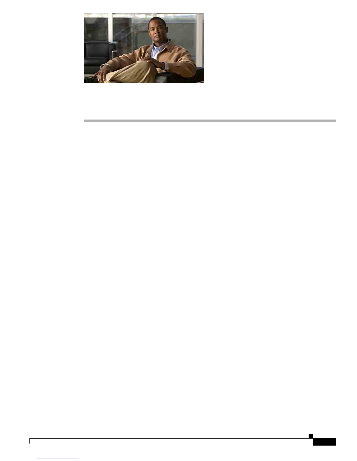
Figure 1-1 and Figure 1-2 show the Cisco CRS 4-slot line card chassis from both the front (PLIM) and
rear (SFC) sides.
Figure 1-1 Front (PLIM) View of Cisco CRS 4-Slot Line Card Chassis
Chapter 1 Overview
1 PLIM slots 4 Air intake
2 RP slots 5 Power supplies (behind air filter)
3 MSC slots
Cisco CRS Carrier Routing System 4-Slot Line Card Chassis Installation Guide
1-2
OL-10971-10
Page 15

Chapter 1 Overview
S
T
A
T
U
S
S
TA
TU
S
STA
T
U
S
STAT
U
S
158296
3
1
2
Chassis Components
Figure 1-2 Rear (SFC) View of the Cisco CRS 4-Slot Line Card Chassis
1 Fan tray 3 Switch fabric card slots
2 AC power plug connectors
The Cisco CRS 4-slot line card chassis contains the following components:
• As many as four MSCs, FPs, or LSPs and four PLIMs. The line card and PLIM are an associated
pair of cards that mate through the chassis midplane. The line card provides the forwarding engine
for Layer 3 routing of user data, and the PLIM provides the physical interface and connectors for
the user data.
Each line card can be associated with several different PLIMs that provide different interface speeds
and technologies. For a full list of available PLIMs, please contact your Cisco sales representative.
OL-10971-10
Cisco CRS Carrier Routing System 4-Slot Line Card Chassis Installation Guide
1-3
Page 16

Chassis Components
Chapter 1 Overview
• A chassis midplane that connects line cards to their associated PLIMs. The midplane design allows
a line card to be removed from the chassis without having to disconnect the cables that are attached
to the associated PLIM. The midplane distributes power, connects the line cards to the switch fabric
cards, and provides control plane interconnections. The midplane is not field replaceable by the
customer.
• One or two route processor cards (RPs). The RPs function as the Cisco CRS 4-slot line card chassis
system controller and provide route processing.
Only one RP is required for system operation. For redundant operation, you can order a second RP
as an option (CRS-4-RP/R). When two RPs are used, only one RP is active at a time. The second
RP acts as a “standby” RP, serving as a backup if the active RP fails.
The RP also monitors system alarms and controls the system fans. LEDS on the front panel indicate
active alarm conditions.
A Performance Route Processor (PRP) is also available for the Cisco CRS 8-slot line card chassis.
Two PRPs perform the same functions as RPs, but provide enhanced performance for both route
processing and system controller functionality.
Note A chassis may not be populated with a mix of RP and PRP cards. Both route processor cards
should be of the same type (RP or PRP).
• Fan tray. The fans pull cool air through the chassis. A removable air filter is located below the PLIM
card cage at the front of the chassis. The fan tray has four fans that provide n+1 redundancy.
• Four switch fabric cards (SFCs). These cards provide the three-stage Benes switch fabric for the
routing system. The switch fabric performs the cross-connect function of the routing system,
connecting every line card (and its associated PLIM) with every other line card (and its associated
PLIM) in the system.
The switch fabric receives user data from one line card and PLIM pair and performs the switching
necessary to route the data to the appropriate egress line card and PLIM pair. The switch fabric is
divided into eight logical planes (four physical planes) that are used to evenly distribute the traffic
across the switch fabric. Each switch fabric card implements two planes of the switch fabric.
• A power system that provides redundant power to the chassis. The power system consists of an AC
power shelf, which contains four AC rectifier modules, or a DC power shelf, which encloses four
DC power supplies. The power shelf (AC or DC as ordered) is pre-installed in the chassis when you
receive the routing system.
The PLIM side of the chassis is considered the front of the chassis, where user data cables attach to the
PLIMs and cool air enters the chassis. The switch fabric card side, which is where warm air is exhausted,
is considered to be the rear of the chassis.
Cisco CRS Carrier Routing System 4-Slot Line Card Chassis Installation Guide
1-4
OL-10971-10
Page 17

Chapter 1 Overview
11
1
2
3
4
9
10
6
5
7
8
12
Chassis Slot Numbers
This section identifies the location and slot numbers for major cards and modules (primarily the
field-replaceable units) that plug into the Cisco CRS 4-slot line card chassis.
Figure 1-3 shows the slot numbering on the front (PLIM) side of the Cisco CRS 4-slot line card chassis.
Figure 1-3 Cisco CRS 4-Slot Chassis Slot Numbering—Front (PLIM) Side
Chassis Slot Numbers
1 MSC slot 0 7 PLIM slot 2
2 MSC slot 1 8 PLIM slot 3
3 MSC slot 2 9 RP slot (RP0)
4 MSC slot 3 10 RP slot (RP1)
5 PLIM slot 0 11 Air intake
6 PLIM slot 1 12 Power shelf (AC or DC)
As shown in Figure 1-3, the Cisco CRS 4-slot line card chassis numbers on the PLIM side of the chassis
include the card cage with the following assignments:
• Four MSC slots (left to right, 0, 1, 2, 3) for MSCs and FPs
• Four PLIM slots (left to right, 0, 1, 2, 3)
• Two route processor card slots, RP0 and RP1
Figure 1-4 shows the slot numbers on the rear (Switch Fabric Card) side of the Cisco CRS 4-slot line
card chassis.
Cisco CRS Carrier Routing System 4-Slot Line Card Chassis Installation Guide
OL-10971-10
1-5
Page 18
Chassis Slot Numbers
158317
1
2
3
4
5
Chapter 1 Overview
Figure 1-4 Cisco CRS 4-Slot Chassis Slot Numbering—Rear (SFC) Side
1 Fan tray (FT0) 4 Switch fabric card slot (SM1)
2 Switch fabric card slot (SM3) 5 Switch fabric card slot (SM0)
3 Switch fabric card slot (SM2)
As shown in Figure 1-4, the slot numbers on the SFC side of the chassis include:
• Fan tray
• Card cage, including four reduced-height SFC slots (SM0 to SM3, right to left)
Cisco CRS Carrier Routing System 4-Slot Line Card Chassis Installation Guide
1-6
OL-10971-10
Page 19

Chapter 1 Overview
158351
Chassis Cable Management
The Cisco CRS 4-slot line card chassis has cable management features for the front (PLIM) side of the
chassis, just above the card cage. The horizontal cable management trays have a special telescoping
feature that allows them to be extended when the chassis is upgraded with higher-density cards. This
extension also helps when installing the cables in the chassis.
Figure 1-5 shows the cable management bracket for the chassis.
Figure 1-5 Cable Management Bracket
Chassis Cable Management
Chassis Cooling System
The Cisco CRS 4-slot line card chassis has a single fan tray containing four fans that cool the chassis
card cage. Cool air flows in at the bottom front of the chassis and flows through the chassis card cage
and through the fans in the fan tray before being expelled through the top rear of the chassis (see
Figure 1-6).
In addition, each power module at the bottom of the chassis has self-contained fans that pull in cool air
from the front of the chassis and exhaust warm air out the rear. Air also flows under the midplane,
through the SFCs, and then the fans to be expelled. There are these two parallel paths for air flow.
A replaceable air filter is located inside the chassis below the PLIM card cage at an angle. In addition,
there is a removable air filter on the front of the power tray air intake grille on the front (PLIM) side of
the chassis.
How often the air filters should be replaced depends on the facility environment. In a dirty environment,
or when you start getting frequent temperature alarms, you should always check the intake grille for
debris, and then check the air filters to see if they need to be replaced.
Note We recommend that you check the air filters once a month. Replace a filter when you notice a significant
amount of dust.
OL-10971-10
Cisco CRS Carrier Routing System 4-Slot Line Card Chassis Installation Guide
1-7
Page 20

Chassis Power System
Air exhaust
Front Rear
210072
Chassis
air inlet
Power supplies
and power shelf
Power shelf
air inlet
Air exhaust
Air filter
Fan tray
Midplane
Chapter 1 Overview
Figure 1-6 Airflow Through the Cisco CRS 4-Slot Line Card Chassis
The Cisco CRS 4-slot line card chassis airflow volumes are as follows:
• Chassis airflow: Up to 880 cubic feet (24,919 liters) per minute
• Power system airflow: Up to 60 cubic feet (1,699 liters) per minute
Chassis Power System
The Cisco CRS Carrier Routing System 4-Slot Line Card Chassis can be configured with either an
AC-input power subsystem or a DC-input power subsystem. The AC power trays are configured for
single-phase AC power module wiring. The power modules and power trays have separate Cisco part
numbers. For additional information, see the appropriate sections in Chapter 2, “Installing and
Removing Power Components.”
Safety Guidelines
Before you perform any procedure in this document, review the safety guidelines in this section to avoid
injuring yourself or damaging the equipment.
The following guidelines are for your safety and to protect equipment. The guidelines do not include all
hazards. Be alert.
1-8
Cisco CRS Carrier Routing System 4-Slot Line Card Chassis Installation Guide
OL-10971-10
Page 21

Chapter 1 Overview
Note Review the safety warnings listed in Regulatory Compliance and Safety Information that are applicable
Preventing Electrostatic Discharge
to your router before installing, configuring, or troubleshooting any installed card.
• Keep the work area clear and dust-free during and after installation. Do not allow dirt or debris to
enter into any laser-based components.
• Do not wear loose clothing, jewelry, or other items that could get caught in the router while working
with line cards, PLIMs, or their associated components.
• Cisco equipment operates safely when used in accordance with its specifications and product-usage
instructions.
Warning
Warning
Warning
Warning
This unit is intended for installation in restricted access areas. A restricted access area is
where access can only be gained by service personnel through the use of a special tool,
lock and key, or other means of security, and is controlled by the authority responsible for
the location.
Only trained and qualified personnel should be allowed to install or replace this equipment.
Statement 49
High leakage current—earth connection essential before connecting to system power
supply.
The chassis should be mounted on a rack that is permanently affixed to the building.
Statement 1049
Statement 37
Statement 342
Preventing Electrostatic Discharge
Electrostatic discharge (ESD) damage, which can occur when electronic cards or components are
improperly handled, results in complete or intermittent failures. We recommend to use an
ESD-preventive strap whenever you handle network equipment or one of its components.
Following are guidelines for preventing ESD damage:
• Always use an ESD-preventive wrist or ankle strap and ensure that it makes good skin contact.
Connect the equipment end of the connection cord to an ESD connection socket on the router or to
a bare metal surface on the chassis.
• Handle a card by its ejector levers, when applicable, or the card’s metal carrier only; avoid touching
the board or connector pins.
• Place a removed card board-side-up on an antistatic surface or in a static-shielding bag. If you plan
to return the component to the factory, immediately place it in a static-shielding bag.
• Avoid contact between the card and clothing. The wrist strap protects the board only from ESD
voltage on the body; ESD voltage on clothing can still cause damage.
OL-10971-10
Cisco CRS Carrier Routing System 4-Slot Line Card Chassis Installation Guide
1-9
Page 22

Recommended Chassis Installation Task Sequence
Recommended Chassis Installation Task Sequence
This section provides the recommended task sequence for installing a new Cisco CRS 4-slot line card
chassis.
Step 1 If your system was shipped with AC power, remove the four AC power cords from the box, and do the
following:
a. Insert all four power cords into the AC power source.
b. Insert the power cords into the AC power plugs at the base of the rear of the chassis.
Step 2 Turn the power enable switches (for your AC or DC power system) to the ON position. For details, see
the “AC Power Supply Cord Illustrations and Plug Types” section on page 2-4.
All power should come up properly. The LEDs above the enable switches should be lit green. The fans
in the front of the chassis should start operating.
Step 3 Install the switch fabric cards (SFCs). For the procedure, see the “How to Install or Remove a Switch
Fabric Card” section on page 4-18.
Step 4 Install the route processors (RPs). For the procedure, see the “How to Install or Remove a Route
Processor Card” section on page 4-24.
Step 5 Install the MSCs, FPs, and LSP line cards. For the procedure, see the “How to Install or Remove an MSC,
FP, or LSP” section on page 4-32.
Step 6 Install the physical layer interface modules (PLIMs). For the procedure, see the “How to Install or
Remove a Physical Layer Interface Module” section on page 4-42.
Chapter 1 Overview
Step 7 If the system was shipped with the grille and doors, install the inlet grille. See the “Installing the Inlet
Grille” section on page 5-1.
Step 8 Install the doors. See the “Installing the Doors” section on page 5-4.
CRS Hardware Compatibility
Table 1-1 lists the compatibility of 40G CRS and 140G CRS fabric, forwarding, and line card
components for the CRS 4-slot system.
Note A router with a mix of 40G and 140G fabric cards is not a supported mode of operation. Such a mode is
temporarily allowed only during the upgrade process.
Cisco CRS Carrier Routing System 4-Slot Line Card Chassis Installation Guide
1-10
OL-10971-10
Page 23

Chapter 1 Overview
CRS Hardware Compatibility
Table 1-1 CRS Compatibility Matrix
Switch Fabric RP/DRP MSC/FP/LSP PLIMS Note
CRS-4-FC/S
(40G)
CRS-4-FC140/S
(140G)
RP-A (CRS-4-RP),
DRP-B (CRS-DRP-B)
RP-A (CRS-4-RP),
DRP-B (CRS-DRP-B)
RP-A (CRS-4-RP),
DRP-B (CRS-DRP-B)
CRS-MSC-B 1OC768-DPSK/C
1OC768-ITU/C
1OC768-POS-SR
4-10GE-ITU/C
8-10GBE
CRS1-SIP-800
|4-10GE
42-1GE
20-1GE-FLEX
2-10GE-WL-FLEX
4-10GBE-WL-XFP
8-10GBE-WL-XFP
CRS-FP40 4-10GE
42-1GE
20-1GE-FLEX
2-10GE-WL-FLEX
CRS-MSC-B 1OC768-DPSK/C
1OC768-ITU/C
1OC768-POS-SR
4-10GE-ITU/C
8-10GBE
CRS1-SIP-800
4-10GE
42-1GE
20-1GE-FLEX
2-10GE-WL-FLEX
4-10GBE-WL-XFP
8-10GBE-WL-XFP
RP-A (CRS-4-RP),
DRP-B (CRS-DRP-B)
PRP
(CRS-4-PRP-6G,
CRS-4-PRP-12G)
PRP
(CRS-4-PRP-6G,
CRS-4-PRP-12G)
PRP (CRS-4-PRP-6G,
CRS-4-PRP-12G)
OL-10971-10
CRS-FP40 4-10GE
42-1GE
20-1GE-FLEX
2-10GE-WL-FLEX
CRS-MSC-140G 14X10GBE-WL-XFP
20X10GBE-WL-XFP
1x100GBE
CRS-FP140 14X10GBE-WL-XFP
20X10GBE-WL-XFP
1x100GBE
CRS-LSP 14X10GBE-WL-XFP
20X10GBE-WL-XFP
1x100GBE
Cisco CRS Carrier Routing System 4-Slot Line Card Chassis Installation Guide
1-11
Page 24

CRS Hardware Compatibility
Chapter 1 Overview
Cisco CRS Carrier Routing System 4-Slot Line Card Chassis Installation Guide
1-12
OL-10971-10
Page 25

CHAP T ER
2
Installing and Removing Power Components
This chapter provides instructions on how to install and remove the Cisco CRS Carrier Routing System
4-Slot Line Card Chassis power components.
This chapter presents the following topics:
• About Installing and Removing the Power Components, page 2-1
• DC Power Systems on the Cisco CRS 4-Slot Router, page 2-7
• Installing a DC Power Shelf, page 2-14
• Removing a DC Power Shelf, page 2-20
• Installing an AC Power Shelf, page 2-24
• Removing an AC Power Shelf, page 2-26
• Installing a Power Supply, page 2-28
• Removing a Power Supply, page 2-30
About Installing and Removing the Power Components
This section contains some general information about the power components.
• Basic Chassis Power Recommendations, page 2-1
• Supplemental Unit Bonding and Grounding Guidelines, page 2-2
• AC Power Supply Cord Illustrations and Plug Types, page 2-4
• Powering the Chassis Up or Down, page 2-6
Basic Chassis Power Recommendations
The Cisco CRS Carrier Routing System 4-Slot Line Card Chassis can be configured with either an
AC-input power subsystem or a DC-input power subsystem. Site power requirements differ depending
on the source voltage used. Follow these precautions and recommendations when planning power
connections to the router:
• Check the power at your site before installation and periodically after installation to ensure that you
are receiving clean power. Install a power conditioner, if necessary.
• Install proper grounding to avoid damage from lightning and power surges.
Cisco CRS Carrier Routing System 4-Slot Line Card Chassis Installation Guide
OL-10971-10
2-1
Page 26

About Installing and Removing the Power Components
Caution A Cisco router must be operated with all its power modules installed at all times for electromagnetic
compatibility (EMC).
The Cisco CRS 4-slot line card chassis requires that at least the power shelves and their components be
installed to operate properly. Two types of power shelves exist: an AC shelf and a DC shelf. An AC
power shelf houses AC rectifiers, while a DC power shelf houses the DC power input module (PIM) and
DC power input shelf (which encloses the DC power supplies). We recommend that you use only one
type of power shelf in a chassis at a time.
Chapter 2 Installing and Removing Power Components
Warning
This unit might have more than one power supply connection. All connections must be removed to
de-energize the unit.
Statement 1028
The Cisco CRS 4-slot line card chassis is shipped fully populated with a power shelf that contains four
power supplies for power redundancy. See the appropriate installation section (see “Installing a DC
Power Shelf” section on page 2-14 or “Installing an AC Power Shelf” section on page 2-24) for detailed
installation information.
As viewed from the front (PLIM) side of the chassis, the left two power supplies feed output A, while
the right two power supplies feed output B.
For 2N redundancy, the power input on rear (SFC) side of the chassis should be from two different
branch sources, with the left two input connections to one branch source and the right two to the other
branch source. With this configuration the router remains fully powered in case one branch source fails.
In normal operation all power supplies should be installed.
Be sure to install the power shelf before installing the power supplies.
Caution If you install a non-Cisco power supply in the chassis, upon its detection as a non-compliant power
supply, the system will shut down. Using non-Cisco power supplies MAY RESULT IN COMPLETE
CHASSIS SHUTDOWN due to insufficient power.
Supplemental Unit Bonding and Grounding Guidelines
Although the router chassis has a safety earth ground connection as part of the power cabling to the
power shelf, the chassis includes an option that allows you to connect the central office ground system
or interior equipment ground system to the supplemental bonding and grounding receptacles on the
router chassis. Two ground studs are located on the rear (SFC) side of the chassis. (see Figure 2-1). This
ground point is also called the network equipment building system (NEBS) bonding and grounding stud.
Note These bonding and grounding receptacles satisfy the Telcordia® NEBS requirements for supplemental
bonding and grounding connections. If you are not installing the router in a NEBS environment, you can
choose to bypass these guidelines and rely on the safety earth ground connection for the power shelf.
Cisco CRS Carrier Routing System 4-Slot Line Card Chassis Installation Guide
2-2
OL-10971-10
Page 27

Chapter 2 Installing and Removing Power Components
S
T
A
T
U
S
S
T
AT
U
S
S
T
A
T
U
S
S
T
A
T
U
S
158392
1
Figure 2-1 NEBS Bonding and Grounding Points (Rear of Chassis)
About Installing and Removing the Power Components
1 NEBS bonding and grounding stud
If you plan to connect the Cisco CRS 4-slot line card chassis system to a network equipment building
system (NEBS)-compliant supplemental bonding and grounding system at the site, you must have the
following:
• A minimum of one ground lug that has two M6 bolt holes with 0.625-inch (15.86-mm) spacing
between them, and a wire receptacle large enough to accept a 6-AWG or larger multistrand copper
wire. The lug is similar to the type used for the DC-input power supply leads. This ground lug is not
available from Cisco Systems. This type of lug is available from electrical-connector vendors, such
as Panduit.
• Two M6 nuts with locking washers (nickel-plated brass is ideal). This hardware is not available
from Cisco Systems; they are available from any commercial hardware vendor.
• A commensurately rated ground wire. The actual wire diameter and length depend on your router
location and site environment. This wire is not available from Cisco Systems; it is available from
any commercial cable vendor.
OL-10971-10
Cisco CRS Carrier Routing System 4-Slot Line Card Chassis Installation Guide
2-3
Page 28

Chapter 2 Installing and Removing Power Components
Cordset rating: 16 A, 250 V
Length: 14 ft 0 in. (4.26 m)
Connector: IEC 60320 C19
Plug: AU20S3
About Installing and Removing the Power Components
Note The DC return of this system should remain isolated from the system frame and chassis (DC-I: Isolated
DC Return).
AC Power Supply Cord Illustrations and Plug Types
This section contains the AC power cord illustrations and a table of power plug types for the Cisco CRS
Carrier Routing System 4-Slot Line Card Chassis for Australia (AU), European (EU), Italy (IT), United
Kingdom (UK), United States (USA), and Japan.
Table 2-1 AC Power Supply Plug Types
Plug Type Country
AU20S3 Australia—Figure 2-2
CEE 7/7 European—Figure 2-3
CEI 23-50 Italian—Figure 2-4
BS 1363 United Kingdom—Figure 2-5
NEMA L6-20 United States and Japan—Figure 2-6
Figure 2-2 CAB-CRS4AC-AU
Cisco CRS Carrier Routing System 4-Slot Line Card Chassis Installation Guide
2-4
OL-10971-10
Page 29

Chapter 2 Installing and Removing Power Components
Cordset rating: 16 A, 250 V
Length: 14 ft 0 in. (4.26 m)
Connector: IEC 60320 C19
Plug: CEE 7/7
Cordset rating: 16 A, 250 V
Length: 14 ft 0 in. (4.26 m)
Connector:
(EN 60320/C19)
Plug:
(CEI 23-50)
Cordset rating: 13 A, 250 V
Length: 14 ft 0 in. (4.26 m)
Plug: BS 1363
13A replaceable fuse
Connector: IEC 60320 C19
Figure 2-3 CAB-CRS4AC-EU
Figure 2-4 CAB-CRS4AC-IT
About Installing and Removing the Power Components
Figure 2-5 CAB-CRS4AC-UK
OL-10971-10
Cisco CRS Carrier Routing System 4-Slot Line Card Chassis Installation Guide
2-5
Page 30

About Installing and Removing the Power Components
Cordset rating: 20 A, 250 V
Length: 14 ft 0 in. (4.26 m)
Connector: IEC 60320 C19
Plug: NEMA L6-20
Figure 2-6 CAB-CRS4AC-US and Japan
Powering the Chassis Up or Down
The chassis does not have a single enable switch that powers the entire chassis and all its components
up and down. (These switches are called enable switches because they enable the power supplies to
produce output voltage and power). Most components on the chassis, such as the power supplies, MSCs,
FPs, PLIMs, and fan trays can be removed or installed in the chassis while it is running.
Before you can power the chassis up, you must complete the following tasks:
Chapter 2 Installing and Removing Power Components
Step 1 Install the appropriate power shelf for your system (see the “Installing a DC Power Shelf” section on
page 2-14 or the “Installing an AC Power Shelf” section on page 2-24).
Step 2 Install the power supplies (see the “Installing a Power Supply” section on page 2-28).
Step 3 Install the route processor (RP) card (see the “Installing an RP or PRP Card” section on page 4-26).
Step 4 Install the input power cables to the input power connectors on the rear of the chassis, and the other end
(plug side) to the AC or DC power source.
Step 5 Activate your power source.
Step 6 Turn the two power shelf enable switches on the rear (SFC) side of the power shelf (see Figure 2-7) to
the ON position.
Note The two enable switches on the rear (SFC) side of the AC power shelf (Figure 2-7) put the chassis in
standby mode; in other words, they only power down the -54VDC output from the power supplies.
Cisco CRS Carrier Routing System 4-Slot Line Card Chassis Installation Guide
2-6
OL-10971-10
Page 31

Chapter 2 Installing and Removing Power Components
STATUS
STATUS
STATUS
STATUS
158455
Figure 2-7 AC Power Enable Switches
DC Power Systems on the Cisco CRS 4-Slot Router
For an illustration of the DC power enable switches, see Figure 2-19.
Note All power cords must be unplugged from wall power to fully remove power from the chassis.
DC Power Systems on the Cisco CRS 4-Slot Router
The Cisco CRS 4-slot line card chassis DC power shelf consists of two major components, as shown in
Figure 2-8:
• DC power input shelf (Cisco product number: CRS-4-DC-INPUT)
Figure 2-8 shows the power supplies installed in the DC power input shelf.
• DC power input module (PIM) (Cisco product number: CRS-4-DC-PIM)
OL-10971-10
Cisco CRS Carrier Routing System 4-Slot Line Card Chassis Installation Guide
2-7
Page 32

DC Power Systems on the Cisco CRS 4-Slot Router
Figure 2-8 DC Power Shelf: DC Power Input Shelf and DC Power Input Module (PIM)
1
Chapter 2 Installing and Removing Power Components
Front orientation
2
Rear orientation
210772
1 DC power input shelf 2 Power input module (PIM)
When installing the DC power shelf, these two components are mated to create the complete DC power
shelf (see the “Installing a DC Power Shelf” section on page 2-14 for details).
The Cisco CRS 4-slot line card chassis DC power system provides 4,000 watts to power the chassis. (To
provide power redundancy, up to 8,000 watts are available.) Each DC-powered chassis contains four DC
power supplies for 2N redundancy. The power input module (PIM) provides the input power
connections. Note that each power connection has two cables: –48 VDC and return. The power input
module (PIM), DC power input shelf, and the power supplies are field replaceable.
The Cisco CRS 4-slot line card chassis requires a total of four dedicated pairs of 60-A DC input power
connections, one pair for each of the power supplies, to provide redundant DC power to the Cisco CRS
4-slot line card chassis midplane.
For full 2N redundancy, we recommend that you have two independent –48 VDC power sources to
provide power to the Cisco CRS 4-slot line card chassis. Connect the two 60-A DC inputs on the left to
one wiring block, and the two 60-A DC inputs on the right to the other wiring block.
Cisco CRS Carrier Routing System 4-Slot Line Card Chassis Installation Guide
2-8
OL-10971-10
Page 33

Chapter 2 Installing and Removing Power Components
DC Power Shelf Guidelines
At sites where the Cisco CRS 4-slot line card chassis is equipped with a DC power input shelf and power
supplies, observe the following guidelines:
• All power connection wiring should follow the rules and regulations in the National Electrical Code
(NEC) and any local codes.
• Each DC-input power entry module connection is rated at 60 A maximum. A dedicated,
commensurately rated DC power source is required for each power supply connection.
• Each power supply requires one –48 VDC input, or four inputs for each power shelf (in which each
input consists of a pair of positive and negative wires), and one power-shelf grounding wire.
• For DC power cables, we recommend that you use commensurately rated, high-strand-count copper
wire cable. Each DC power supply requires one –48 VDC input, which means that there are two
wires for each power supply, or eight total wires (four pairs) for each power shelf, plus the
grounding wire. The length of the wires depends on the router’s location. These wires are not
available from Cisco Systems; they are available from any commercial vendor.
• DC power cables must be terminated by cable lugs at the power-shelf end. The lugs should be dual
hole and able to fit over M6 terminal studs at 0.625-in (15.88-mm) centers (for example, Panduit
part number LCD2-14A-Q or equivalent) (see Figure 2-9).
DC Power Systems on the Cisco CRS 4-Slot Router
Figure 2-9 DC Power Cable Lug
End View
0.60
Ø 0.27
2 holes
0.25 0.380.63
0.10
Color Coding of the Source DC Power Cable
The color coding of the source DC power cable leads depends on the color coding of the site DC power
source. Typically, green or green and yellow indicates that the cable is a ground cable. Because no color
code standard exists for the source DC wiring, you must ensure that the power cables are connected to
the DC-input power shelf terminal studs in the proper positive (+) polarity and negative (–) polarity.
DC Cable Polarity Labels
Sometimes, the source DC cable leads might have a positive (+) or a negative (–) label. This label is a
relatively safe indication of the polarity, but you must verify the polarity by measuring the voltage
between the DC cable leads. When making the measurement, the positive (+) lead and the negative (–)
lead must always match the (+) and (–) labels on the power shelf.
All measurements in inches
2.40
Crimp area
210840
Caution The DC-input power supplies contain circuitry to prevent damage due to reverse polarity, but you should
correct a reverse-polarity condition immediately.
OL-10971-10
Cisco CRS Carrier Routing System 4-Slot Line Card Chassis Installation Guide
2-9
Page 34

DC Power Systems on the Cisco CRS 4-Slot Router
210614
B1
(RTN) (-48V/-60V)
+
–
B0
B0B1
ON
Side B
(RTN) (-48V/-60V)
+
–
A1
(RTN) (-48V/-60V)
+
–
A0
(RTN) (-48V/-60V)
+
–
A0A1
ON
Side A
SIDE A
SIDE B
3
6
1
2
4
5
Table 2-2 DC Input Current and Voltage Information
Nominal input voltage Supports –48 VDC and –60 VDC systems
Input line current 50 A maximum at –48 VDC
Inrush current 60 A peak at –75 VDC
Note When wiring the DC power shelf, be sure to attach the ground wire first. When removing the wiring, be
sure to remove the ground wire last. The ground wire must be attached with a torque value of 30 in-lb.
The power cables should also be attached with a torque value of 30 in-lb.
Chapter 2 Installing and Removing Power Components
(range: –40 to –72 VDC)
Note The turn-on voltage of the DC power supplies
is –43.5 +/- 0.5 VDC. When a power supply is
powered on, it continues to operate down to an
input voltage of –40 VDC.
40 A maximum at –60 VDC
(maximum for 1 ms)
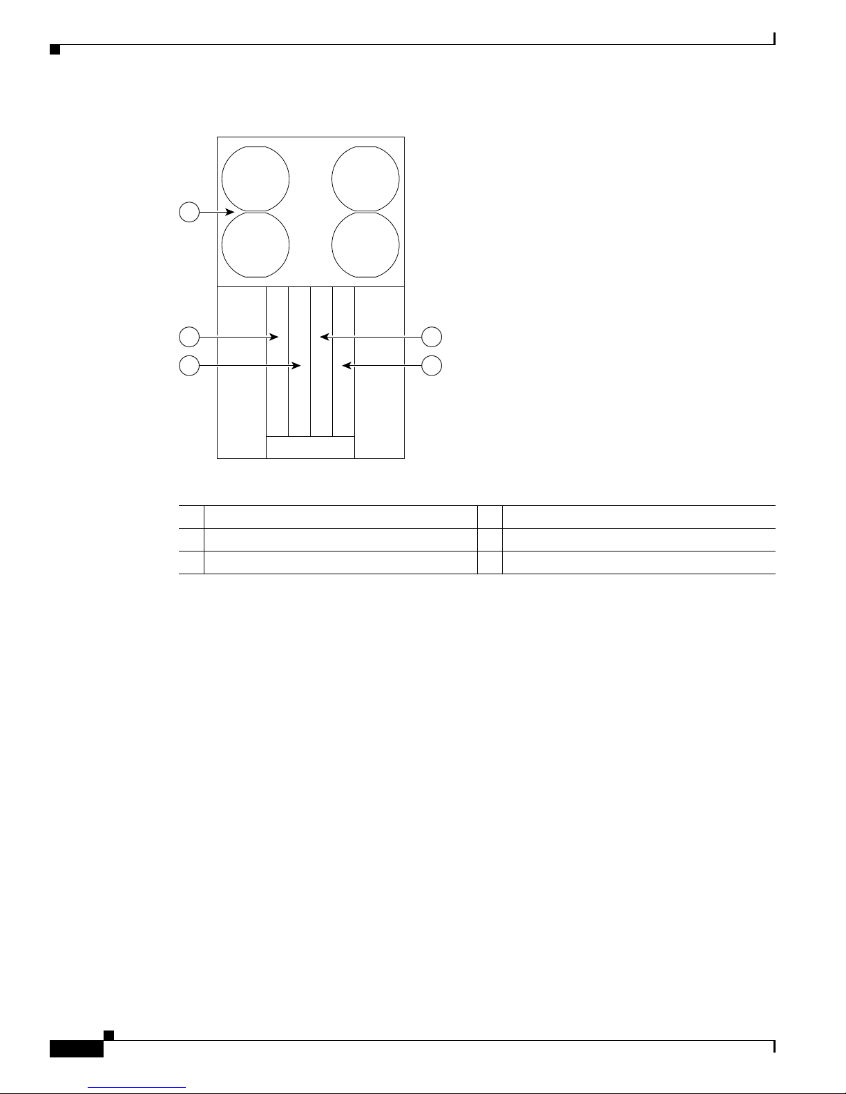
Wiring Block on the PIM
Each wiring block on the power input module (PIM) contains four sets of terminals, two positive and
two negative (see Figure 2-10). Each wiring block is covered by a plastic block cover that snaps onto
the wiring block and is secured by a screw to a torque value of 50 in.-lb.
You must remove the block cover before you work with the wires.
Figure 2-10 Power Input Module (PIM)
Cisco CRS Carrier Routing System 4-Slot Line Card Chassis Installation Guide
2-10
1 Power supply B1 wiring block 4 Power supply A1 wiring block
2 Power supply B0 wiring block 5 Power supply A0 wiring block
3 Power shelf coupling screw 6 Ground lug nuts
OL-10971-10
Page 35

Chapter 2 Installing and Removing Power Components
210614
B1
(RTN) (-48V/-60V)
+
–
B0
B0B1
ON
SIDE B
Side B
(RTN) (-48V/-60V)
+
–
A1
(RTN) (-48V/-60V)
+
–
A0
(RTN) (-48V/-60V)
+
–
A0A1
ON
Side A
SIDE A
A0A1
ON
B0B1
ON
Input-Power-Present LEDs
The DC power Input-Power-Present LEDs provide a visual indication to service personnel that there is
voltage present across the input terminal’s connections (see Figure 2-11). The LED provides a warning
to the service person that there is power present.
Note Power should be disconnected before servicing the input power connections. Always check for
hazardous voltage with a multimeter device before servicing the router.
Figure 2-11 Input-Power-Present LEDs
DC Power Systems on the Cisco CRS 4-Slot Router
The input-power-present LED starts to light up when the input voltage reaches 20 VDC; the LED gets
brighter as voltage increases. The input-power-present LED is fully lit when the input voltage reaches
38 VDC.
Note If an input-power-present LED is not lit, check for: 1) the presence of voltage, and 2) the polarity
of the corresponding wiring block.
DC Power Wire Characteristics
For signal degradation to be averted, a conductor must be large enough to prevent its impedance from
creating a voltage drop equal to 2 percent of the reference voltage. Also, the gauge of the earth conductor
must be equal to or larger then that of the –48 VDC (or –48 VDC return) conductor. This latter
requirement is for safety. Full fault redundancy is achieved by having conductors of equal size for the
protective earth ground and the –48 VDC return of the switch.
For site preparation, proper wire size and insulation must be selected. For a planned power distribution,
calculation must be done prior to distribution to meet the proper voltage drop and temperature rise.
For wire gauges that prevent unacceptable voltage drops over different lengths of copper wire, see
Table 2-3. For the resistance of 1000 feet of copper wire for each gauge of wire, see Table 2 - 4. These
references are for planning purposes and might be further subject to local laws and practices.
Table 2-3 provides the gauges of wire needed for wire lengths and DC power currents. The units of
measurement are in American wire gauge (AWG).
OL-10971-10
Cisco CRS Carrier Routing System 4-Slot Line Card Chassis Installation Guide
2-11
Page 36

Chapter 2 Installing and Removing Power Components
DC Power Systems on the Cisco CRS 4-Slot Router
Note Table 2-3 and Table 2-4 are for reference; we recommend using at least 50 A of DC current and 6-gauge
wire.
Table 2-3 Wire Gauge for Current Loads Over Copper Wire Lengths
DC Current (Amps) 25 Feet 50 Feet 75 Feet 100 Feet 150 Feet 200 Feet 400 Feet
5 A 18 AWG 14 AWG 14 AWG 12 AWG 10 AWG 8 AWG 6 AWG
10 A 14 AWG 12 AWG 10 AWG 8 AWG 8 AWG 6 AWG 2 AWG
15 A 14 AWG 10 AWG 8 AWG 8 AWG 6 AWG 4 AWG 2 AWG
20 A 12 AWG 8 AWG 8 AWG 6 AWG 4 AWG 2 AWG 0 AWG
25 A 12 AWG 8 AWG 6 AWG 4 AWG 4 AWG 2 AWG 0 AWG
30 A 10 AWG 8 AWG 6 AWG 4 AWG 2 AWG 2 AWG 00 AWG
35 A 10 AWG 6 AWG 4 AWG 2 AWG 2 AWG 1 AWG 000 AWG
40 A 8 AWG 6 AWG 2 AWG 2 AWG 2 AWG 0 AWG 000 AWG
45 A 8 AWG 6 AWG 4 AWG 2 AWG 1 AWG 0 AWG 0000 AWG
50 A 8 AWG 4 AWG 4 AWG 2 AWG 1 AWG 00 AWG N/A
55 A 8 AWG 4 AWG 2 AWG 2 AWG 0 AWG 00 AWG N/A
60 A 8 AWG 4 AWG 2 AWG 2 AWG 0 AWG 00 AWG N/A
65 A 6 AWG 4 AWG 2 AWG 1 AWG 0 AWG 000 AWG N/A
70 A 6 AWG 4 AWG 2 AWG 1 AWG 00 AWG 000 AWG N/A
75 A 6 AWG 4 AWG 2 AWG 1 AWG 00 AWG 000 AWG N/A
100 A 4 AWG 2 AWG 1 AWG 00 AWG 000 AWG N/A N/A
Cisco CRS Carrier Routing System 4-Slot Line Card Chassis Installation Guide
2-12
OL-10971-10
Page 37

Chapter 2 Installing and Removing Power Components
Table 2-4 provides the correlation between wire gauge and the resistance (in Ohms for each 1000 feet
of wire) for copper wire.
Table 2-4 Resistance for Each Gauge of Copper Wire
Wire Gauge (AWG) Ohms for Each 1000 Feet of Wire
0000 AWG 0.0489
000 AWG 0.0617
00 AWG 0.0778
0 AWG 0.098
1 AWG 0.1237
2 AWG 0.156
3 AWG 0.1967
4 AWG 0.248
5 AWG 0.3128
6 AWG 0.3944
7 AWG 0.4971
8 AWG 0.6268
9 AWG 0.7908
10 AWG 0.9968
11 AWG 1.257
12 AWG 1.5849
13 AWG 1.9987
14 AWG 2.5206
15 AWG 3.1778
16 AWG 4.0075
17 AWG 5.0526
18 AWG 6.3728
19 AWG 8.0351
20 AWG 10.1327
21 AWG 12.7782
22 AWG 16.1059
DC Power Systems on the Cisco CRS 4-Slot Router
OL-10971-10
Cisco CRS Carrier Routing System 4-Slot Line Card Chassis Installation Guide
2-13
Page 38

Installing a DC Power Shelf
Installing a DC Power Shelf
This section describes how to install a DC power shelf in the Cisco CRS 4-slot line card chassis.
The DC power shelf encloses four power supplies and the power distribution connections and wiring.
The DC power input shelf is installed in the front of the chassis; the power input module (PIM) is
installed in the rear of the chassis.
We recommend that you have two separate, redundant –48 VDC power battery sources to provide power
to the Cisco CRS 4-slot line card chassis. Connect the two input pair 60-A DC inputs on the left to one
–48 VDC power source, and the input pair 60-A DC inputs on the right to the other –48 VDC power
source.
Sequence of Tasks
The sequence of tasks required to install the DC power shelf is:
1. Remove the rear power access panels.
2. Install the DC power input module (PIM).
3. Install the DC power input shelf.
4. Mate and secure the power input module to the DC power input shelf.
5. Connect the grounding cable and the power input cables.
Chapter 2 Installing and Removing Power Components
6. Install the DC power supplies.
Prerequisites
Power down the Cisco CRS 4-slot line card chassis.
Tip We recommend that you do this procedure with the line card chassis mounted in a rack with sufficient
space for bottom and side access to the screws.
Required Tools and Equipment
You need the following tools and parts to perform this task:
• ESD-preventive wrist strap
• Medium flat-blade screwdriver
• Number 1 Phillips screwdriver
• Number 2 Phillips screwdriver
• 5-mm Allen wrench
• 10-mm hex socket wrench
• DC power input shelf (Cisco product number: CRS-4-DC-INPUT)
• DC power input module (PIM) (Cisco product number: CRS-4-DC-PIM)
• DC power supplies (Cisco product number: CRS-4-DC-SUPPLY)
Cisco CRS Carrier Routing System 4-Slot Line Card Chassis Installation Guide
2-14
OL-10971-10
Page 39

Chapter 2 Installing and Removing Power Components
Note This procedure assumes that the Cisco CRS 4-slot line card chassis is already mounted in a rack with
sufficient room to access the sides and the bottom of the chassis.
Steps
To install the DC power shelf, follow these steps:
Step 1 Attach the ESD-preventive wrist strap to your wrist and connect its leash to one of the ESD connection
sockets on the front (PLIM) side of the chassis or a bare metal surface on the chassis.
Step 2 If the AC power shelf is currently installed, remove it from the front of the chassis. (For details, see the
“Removing an AC Power Shelf” section on page 2-26.)
Removing the Rear Power Access Panels
Before you can install the power input module, you must remove the rear power access panels.
Step 3 From the rear of the chassis, use a medium Phillips screwdriver to remove the rear power access panels
(located on the bottom right and bottom left rear of the chassis). Remove the screws shown in
Figure 2-12.
Installing a DC Power Shelf
Tip One screw on each side is located under the chassis (as shown in Figure 2-12). To access this screw
safely, the chassis must be in a rack with adequate space below the chassis.
Figure 2-12 Removing the Rear Power Access Panels
S
U
TAT
Step 4
S
Unscrew the coupling screw from each panel with a medium flat-blade screwdriver. Set aside the access
S
U
T
TA
S
S
U
T
TA
S
TA
S
S
TU
SIDE A
panels and their screws.
210619
Note You will need these screws later when you install the power input module (PIM).
OL-10971-10
Cisco CRS Carrier Routing System 4-Slot Line Card Chassis Installation Guide
2-15
Page 40

Installing a DC Power Shelf
Installing the DC Power Input Module
Step 5 From the rear of the chassis, insert the DC power input module (PIM) into the open power bay (see
Figure 2-13).
Note The PIM weighs 6.5 lb (2.9 kg).
Figure 2-13 Inserting the DC Power Input Module (PIM)
+
B1
(RTN) (-48V/-60V)
Chapter 2 Installing and Removing Power Components
STATUS
STATUS
STATUS
STATUS
–
+
B0
(RTN)
–
(-48V/-60V)
ON
SIDE B
B1
B0
Side B
SIDE A
Side A
+
A1
(RTN)
–
(-48V/-60V)
ON
A0A1
+
A0
(RTN)
–
(-48V/-60V)
210622
Step 6 Reinsert the No. 2 Phillips screws taken from the rear power access panels into their respective holes:
one on each side, three in front, and one underneath the chassis.
Installing the DC Power Input Shelf
Caution The DC power input shelf can only be inserted into the chassis when all power is removed from the
chassis.
Step 7 Go to the front of the chassis. To install the DC power input shelf, follow these steps:
a. To prepare the chassis for installing the DC power input shelf, remove the inlet grille from the
bottom of the chassis (for the procedure, see the “Removing the Inlet Grille” section on page 5-3).
b. Holding the DC power input shelf underneath with one hand and steadying it with the other, lift the
DC power input shelf up and slide it part way into the power shelf slot on the front (PLIM) side of
the chassis. Be sure to center the DC power input shelf in the slot when you slide it in (see
Figure 2-14).
Caution An empty DC power input shelf weighs about 15.5 lb (7 kg). To prevent injury when lifting
the shelf, keep your back straight and lift with your legs, not your back. Avoid sudden twists
or lateral moves.
c. Slide the DC power input shelf fully into the chassis. Be sure that the lever handles are aligned with
the lever handle catches on the chassis casing.
d. To lock the power input shelf into position, lift the lever handles up.
Cisco CRS Carrier Routing System 4-Slot Line Card Chassis Installation Guide
2-16
OL-10971-10
Page 41

Chapter 2 Installing and Removing Power Components
ST
A
TU
S
S
T
A
TU
S
S
T
A
TU
S
STA
TU
S
210621
S
T
A
T
U
S
S
T
AT
U
S
S
T
A
T
U
S
S
T
A
T
U
S
210623
B1
(R
T
N
)
(-4
8
V
/-6
0
V
)
+
–
B0
B0
B1
ON
Side B
(R
T
N
)
(-4
8
V
/-6
0
V
)
+
–
A1
(
R
TN
)
(-
4
8
V
/-
6
0
V
)
+
–
A0
(
R
T
N
)(-4
8
V
/-6
0
V
)
+
–
A0A1
ON
Side A
SIDE A
SIDE B
1 2
Figure 2-14 Inserting the DC Power Input Shelf
Securing the PIM to the DC Power Input Shelf
Step 8 Go to the rear of the chassis. To mate the PIM to the DC power input shelf, push the PIM firmly but
carefully into the power input shelf.
Step 9 To secure the input power module connections to the power input shelf, use a 5-mm Allen wrench to
tighten the power shelf coupling screw into the DC power input shelf (see Figure 2-15).
Installing a DC Power Shelf
Figure 2-15 Power Shelf Coupling Screw
1 Power shelf coupling screw 2 Ground lug nuts
Connecting the Grounding Cable and Power Input Cables
Step 10 On the PIM, use a 10-mm hex socket wrench to connect the grounding cable (see item 2 in Figure 2-15).
OL-10971-10
Cisco CRS Carrier Routing System 4-Slot Line Card Chassis Installation Guide
2-17
Page 42

Installing a DC Power Shelf
210613
B1
(RTN
)
(-48V/-60V)
+
–
B0
B0B1
ON
Side B
(RTN
)
(-48V/-60V)
+
–
A1
(RTN) (-48V/-60V)
+
–
A0
(RTN) (-48V/-60V)
+
–
A0
A1
ON
Side A
SIDE A
SIDE B
Note When wiring the power shelf, be sure to attach the ground wire first. When removing the wiring,
Step 11 On the PIM, use a 10-mm hex socket wrench to hook up the DC input power cables. Connect the four
60 A DC cables (two cables per input) on the left to one wiring block, and the four 60A DC cables on
the right to the other wiring block (see Figure 2-16).
Note The DC input power cables should also be attached with a torque value of 30 in-lb.
Color Coding of the Source DC Power Cable. The color coding of the source DC power cable leads
depends on the color coding of the site’s DC power source. Typically, green or green and yellow
indicates that the cable is a ground cable. Because no color code standard exists for the source DC
wiring, you must ensure that the power cables are connected to the DC-input power shelf terminal studs
in the proper positive (+) polarity and negative (–) polarity.
DC Cable Polarity Labels. Sometimes, the source DC cable leads might have a positive (+) or a
negative (–) label. This label is a relatively safe indication of the polarity, but you must verify the
polarity by measuring the voltage between the DC cable leads. When making the measurement, the
positive (+) lead and the negative (–) lead must always match the (+) and (–) labels on the power shelf.
Chapter 2 Installing and Removing Power Components
be sure to remove the ground wire last. The ground wire must be attached with a torque value of
30 in-lb.
Figure 2-16 DC Power Shelf Cable Cabling
Step 12
Reattach both wiring block covers (see Figure 2-16).
a. Snap the cover over the wiring block so that it snaps closed.
b. Use a number 1 Phillips screwdriver to tighten the capture screw.
Cisco CRS Carrier Routing System 4-Slot Line Card Chassis Installation Guide
2-18
OL-10971-10
Page 43

Chapter 2 Installing and Removing Power Components
S
T
A
T
U
S
S
T
A
T
U
S
S
T
A
T
U
S
S
T
A
T
U
S
210620
Note The wiring block covers can be oriented to route the wire cabling from the top or the bottom of
the covers.
Installing the DC Power Supplies
Step 13 Go to the front of the chassis. Install the four DC power supplies into the power input shelf (see
Figure 2-17). For details, see the “Installing a Power Supply” section on page 2-28.
Note Each DC power supply weighs 4.5 lb (2 kg).
Figure 2-17 Installing DC Power Supplies
Installing a DC Power Shelf
OL-10971-10
Step 14
Install the air filter (see Figure 2-18). For the procedure, see the “Installing the Chassis Air Filter”
section on page 3-7.
Cisco CRS Carrier Routing System 4-Slot Line Card Chassis Installation Guide
2-19
Page 44

Removing a DC Power Shelf
STATUS
STATUS
STATUS
STATUS
158365
1
3
2
4
Figure 2-18 Chassis Air Filter
Chapter 2 Installing and Removing Power Components
1 Chassis air filter 3 Power tray and power supplies
2 Air intake grille 4 Power tray air filter
Step 15
Install the inlet grille. See the “Installing the Inlet Grille” section on page 5-1.
Removing a DC Power Shelf
This section describes how to remove a DC power shelf from the Cisco CRS 4-slot line card chassis. The
DC power shelf is comprised of both the DC power input shelf and the DC power input module (PIM).
The DC power shelf encloses four power supplies and the power distribution connections and wiring
blocks.
The DC power input shelf is in the front of the chassis; the power input module (PIM) is in the rear of
the chassis.
Sequence of Tasks
The sequence of tasks required to remove the DC power shelf is as follows:
1. Bring down all power to the chassis.
2. Disconnect the input power cables.
3. Disconnect the grounding cable.
4. Remove the air intake (inlet) grille.
5. Remove all DC power supplies.
6. Remove the DC power input shelf.
7. Remove the DC power input module (PIM).
Cisco CRS Carrier Routing System 4-Slot Line Card Chassis Installation Guide
2-20
OL-10971-10
Page 45

Chapter 2 Installing and Removing Power Components
Prerequisites
Power down the Cisco CRS 4-slot line card chassis (as described in the steps below).
Required Tools and Equipment
You need the following tools and parts to perform this task:
• ESD-preventive wrist strap
• Medium flat-blade screwdriver
• Number 1 Phillips screwdriver
• Number 2 Phillips screwdriver
• 5-mm Allen wrench
• 10-mm hex socket wrench
Note This procedure assumes that the Cisco CRS 4-slot line card chassis is already mounted in a rack with
sufficient room to access the sides and the bottom of the chassis.
Removing a DC Power Shelf
Steps
To remove the DC power shelf, follow these steps:
Step 1 Attach the ESD-preventive wrist strap to your wrist and connect its leash to one of the ESD connection
sockets on the front (PLIM) side of the chassis or a bare metal surface on the chassis.
Bring Down All Power to the Chassis
Step 2 Power down the chassis:
a. Go to the rear of the chassis. On the PIM, set both power shelf enable switches to OFF (see
Figure 2-19). Now the system’s boards and fans have no power.
b. Unplug the DC power supplies.
c. Disconnect input power from the customer source.
OL-10971-10
Cisco CRS Carrier Routing System 4-Slot Line Card Chassis Installation Guide
2-21
Page 46

Removing a DC Power Shelf
S
T
A
T
U
S
S
T
AT
U
S
S
T
A
T
U
S
S
T
A
T
U
S
210861
B1
(R
T
N
)
(4
8
V
/-
6
0
V
)
+
–
B0
B0
B1
ON
Side B
(R
T
N
)
(-4
8
V
/-6
0
V
)
+
–
A1
(R
TN
)
(-
4
8
V
/-
6
0
V
)
+
–
A0
(R
T
N
)(-
4
8
V
/-6
0
V
)
+
–
A0A1
ON
Side A
SIDE A
SIDE B
1
Figure 2-19 DC Power Shelf Enable Switches
Chapter 2 Installing and Removing Power Components
1 DC power shelf enable switches
Step 3
Remove both wiring block covers (see Figure 2-20).
a. Use a number 1 Phillips screwdriver to loosen the capture screw.
b. Snap off the cover over the wiring block.
Disconnect the Input Power Cables and Grounding Cable
Step 4 Use a 10-mm hex socket wrench to disconnect the DC input power cables.
Disconnect the four 60 A DC cables (two cables per input) on the left from one wiring block, and the
four 60 A DC cables on the right from the other wiring block (see Figure 2-20).
Step 5 Use a 10-mm hex socket wrench to disconnect the grounding cable (see Figure 2-20).
Cisco CRS Carrier Routing System 4-Slot Line Card Chassis Installation Guide
2-22
OL-10971-10
Page 47

Chapter 2 Installing and Removing Power Components
210863
B1
(RTN
)
(-48V/-60V)
+
–
B0
B0B1
ON
Side B
(RTN
)
(-48V/-60V)
+
–
A1
(RTN) (-48V/-60V)
+
–
A0
(RTN) (-48V/-60V)
+
–
A0
A1
ON
Side A
SIDE A
SIDE B
2
1
Figure 2-20 Removing Wiring Block Covers and DC Input Power Cables
Removing a DC Power Shelf
1 Power shelf coupling screw 2 Grounding lug nuts
Step 6
With a 5-mm Allen wrench, loosen the power shelf coupling screw (see item 1 in Figure 2-20). This will
allow you to remove the DC power input shelf from the chassis (as described below).
Step 7 Go to the front of the chassis. Remove the inlet grille. For the procedure, see the “Removing the Inlet
Grille” section on page 5-3.
Step 8 Remove the four DC power supplies. For the procedure, see the “Removing a Power Supply” section on
page 2-30.
Remove the DC Power Input Shelf
Step 9 While still in the front of the chassis, you can now remove the DC power input shelf. To remove the DC
power input shelf, follow these steps:
Caution An empty DC power input shelf weighs about 15.5 lb (7 kg). To prevent injury when lifting
the shelf, keep your back straight and lift with your legs, not your back. Avoid sudden twists
or lateral moves.
OL-10971-10
a. To unlock the power input shelf, pull the lever handles down (see Figure 2-21).
b. Holding the DC power input shelf underneath with one hand and steadying it with the other, lift the
DC power input shelf up and slide it part way out of the power shelf slot.
c. Slide the DC power input shelf fully out of the chassis. Set the power input shelf carefully aside.
Cisco CRS Carrier Routing System 4-Slot Line Card Chassis Installation Guide
2-23
Page 48

Installing an AC Power Shelf
S
TA
TU
S
STA
T
U
S
S
TA
TU
S
STA
TU
S
210862
Figure 2-21 Removing the DC Power Input Shelf
Remove the DC Power Input Module (PIM)
Step 10 Go to the rear of the chassis. Remove the DC power input module (PIM).
a. With a Number 2 Phillips screwdriver, remove the first set of eight screws—six screws in the front
of the chassis, two on the outside right and left sides of the chassis (see Figure 2-22).
b. Remove the additional two screws underneath the chassis (one on the left side, one on the right side)
(see Figure 2-22).
Chapter 2 Installing and Removing Power Components
c. With one hand gripping the handle and one hand underneath the module, carefully remove the PIM
from the chassis, then set it aside.
Figure 2-22 Removing the DC Power Input Module (PIM)
STATUS
STATUS
STATUS
STATUS
+
B1
(RTN) (-48V/-60V)
–
+
B0
(RTN)
–
(-48V/-60V)
ON
SIDE B
B1
B0
Side B
SIDE A
Side A
+
A1
(RTN)
–
(-48V/-60V)
ON
A0A1
+
A0
(RTN)
–
(-48V/-60V)
210622
Installing an AC Power Shelf
This section describes how to install an AC power shelf in the Cisco CRS 4-slot line card chassis. The
power shelf encloses four power supplies and the power distribution connections and wiring. The AC
power shelf is installed in the front (PLIM) side of the chassis.
Cisco CRS Carrier Routing System 4-Slot Line Card Chassis Installation Guide
2-24
OL-10971-10
Page 49

Chapter 2 Installing and Removing Power Components
158348
The AC-powered chassis contains a single AC power shelf containing four AC power supplies. Each AC
power supply converts input AC power to the –54 VDC used by the Cisco CRS 4-slot line card chassis.
The AC power shelf is configured for single-phase AC power supply wiring (two wires + ground), and
is safety-rated at 110 to 240 VAC nominal, 50 to 60 Hz (4x) 11A.
For additional power details, see Cisco CRS Carrier Routing System 4-Slot Line Card Chassis System
Description, or in this document, see Appendix A, “Cisco CRS 4-Slot Line Card Chassis
System Specifications.”
For complete information on regulatory compliance and safety, see Cisco CRS Carrier Routing System
Regulatory Compliance and Safety Information.
Prerequisites
Remove the air intake grille from the bottom of the chassis.
Required Tools and Equipment
You need the following tools and parts to perform this task:
• ESD-preventive wrist strap
• Medium flat-blade screwdriver
Installing an AC Power Shelf
• AC Power shelf (Cisco product number: CRS-4-AC-SHELF)
Figure 2-23 shows the AC power shelf.
Figure 2-23 AC Power Shelf
OL-10971-10
Cisco CRS Carrier Routing System 4-Slot Line Card Chassis Installation Guide
2-25
Page 50

Removing an AC Power Shelf
Steps
Step 1 Attach the ESD-preventive wrist strap to your wrist and connect its leash to one of the ESD connection
Step 2 Remove the air intake grille from the bottom of the chassis.
Step 3 Holding the AC power shelf underneath with one hand and steadying it with the other, lift the shelf up
Step 4 Slide the AC power shelf fully into the chassis. Be sure that the lever handles are aligned with the lever
Chapter 2 Installing and Removing Power Components
To install an AC power shelf, use Figure 2-23 as a reference and follow these steps:
sockets on the front (PLIM) side of the chassis or a bare metal surface on the chassis.
and slide it partway into the power shelf slot on the front (PLIM) side of the chassis. Be sure to center
the shelf in the slot when you slide it in.
Caution An empty AC power shelf weighs about 7.0 lb (3.2 kg). To prevent injury when lifting the
shelf, keep your back straight and lift with your legs, not your back. Avoid sudden twists or
lateral moves.
handle catches on the chassis casing.
Caution When inserting the power shelf, carefully guide the shelf in to prevent the power switch from
hitting the edge of the power shelf opening. If possible, have a second person guide the power
shelf from the rear of the unit.
Step 5 Lift the lever handles up to lock the tray into position.
Step 6 Use the flat-blade screwdriver to turn the two captive screws that connect the rear of the chassis to the
power shelf, and tighten them fully.
Caution Be sure to attach the plugs carefully; incorrectly attached plugs can damage the chassis.
What to Do Next
After performing this task, install the power supplies (see the “Installing a Power Supply” section on
page 2-28), and replace any chassis cosmetic cover plates.
Removing an AC Power Shelf
This section describes how to remove an AC power shelf from the Cisco CRS 4-slot line card chassis.
The AC power shelf encloses four power supplies and the power distribution connections and wiring.
The AC power shelf is installed in the front (PLIM) side of the chassis. For more details on the power
systems see the “About Installing and Removing the Power Components” section on page 2-1. For
complete information on regulatory compliance and safety, see Cisco CRS Carrier Routing System
Regulatory Compliance and Safety Information.
Cisco CRS Carrier Routing System 4-Slot Line Card Chassis Installation Guide
2-26
OL-10971-10
Page 51

Chapter 2 Installing and Removing Power Components
Caution Prior to removing the AC power shelf, to reduce the risk of damage, ensure that the rear panel fasteners
are disengaged, the input power cables are disconnected, and the air intake (inlet) grille is removed.
See Figure 2-23 for an illustration of the AC power shelf.
Prerequisites
Before performing this task, you must first remove the air intake grille from the bottom of the chassis,
power down the chassis (see the “AC Power Supply Cord Illustrations and Plug Types” section on
page 2-4), and detach the power cords.
Required Tools and Equipment
You need the following tools to perform this task:
• ESD-preventive wrist strap
• Medium flat-blade screwdriver
Removing an AC Power Shelf
Steps
To remove an AC power shelf, follow these steps:
Step 1 Attach the ESD-preventive wrist strap to your wrist and connect its leash to one of the ESD connection
sockets on the front (PLIM) side of the chassis or a bare metal surface on the chassis.
Step 2 Remove all four power supplies from the shelf you are removing. (See the “Removing a Power Supply”
section on page 2-30.)
Step 3 Remove the power cables from the power from the four power inlets.
Step 4 While facing the rear (SFC) side of the chassis, use the screwdriver to loosen the two captive screws that
connect the rear of the chassis to the power shelf by turning them counterclockwise.
Step 5 Pull the lever handles down with both hands and slide the AC power shelf partway from the slot in the
chassis.
Caution An empty AC power shelf weighs about 7.0 lb (3.2 kg). To prevent injury when lifting the
shelf, keep your back straight and lift with your legs, not your back. Avoid sudden twists or
lateral moves.
Step 6 Placing one hand underneath the AC power shelf and pulling on it and steadying it with the other hand,
slide the shelf completely from the chassis. (If attached, be sure to thread the power cable through the
chassis carefully.)
Step 7 Set the AC power shelf carefully aside.
OL-10971-10
Cisco CRS Carrier Routing System 4-Slot Line Card Chassis Installation Guide
2-27
Page 52

Installing a Power Supply
158349
What to Do Next
After performing this task, you may install a replacement power shelf (see the “Installing an AC Power
Shelf” section on page 2-24), install the power supplies (see the “Installing a Power Supply” section on
page 2-28), and replace any front chassis cosmetic covers.
Installing a Power Supply
This section describes how to install an AC or DC power supply in the Cisco CRS 4-slot power shelf.
The AC power supply converts facility AC power into the DC power necessary to power the cards and
modules in the chassis. Each AC and DC power supply has its own pair of cooling fans, which draws air
through the power supply.
For complete information on regulatory compliance and safety, see Cisco CRS Carrier Routing System
Regulatory Compliance and Safety Information.
Figure 2-24 shows a power supply.
Figure 2-24 Power Supply
Chapter 2 Installing and Removing Power Components
Prerequisites
Before performing this task, make sure that the power shelf has been installed (see the “Installing an AC
Power Shelf” section on page 2-24 or the “Installing a DC Power Shelf” section on page 2-14); remove
any cosmetic covers.
Required Tools and Equipment
You need the following tools and part to perform this task:
• ESD-preventive wrist strap
• Power supply
Cisco CRS Carrier Routing System 4-Slot Line Card Chassis Installation Guide
2-28
OL-10971-10
Page 53

Chapter 2 Installing and Removing Power Components
158465
2
1
Steps
To install a power supply, follow these steps:
Step 1 Attach the ESD-preventive wrist strap to your wrist and connect its leash to one of the ESD connection
sockets on the front (PLIM) side of the chassis or a bare metal surface on the chassis.
Step 2 Using two hands to support and guide the power supply, slide it partway into the power tray on the front
(PLIM) side of the chassis.
Step 3 Make sure that the power supply door grille is in the open position (see Figure 2-25).
Figure 2-25 Power Supply Door Grille in Open Position
Installing a Power Supply
1 Power supply door grille 2 Power supply door latch
Step 4
Slide the power supply into the power shelf until the connector on the back of the module meets the
connector on the backplane of the AC or DC power shelf.
Caution A power supply weighs about 4.5 lb (2 kg). You should use two hands when handling a
module.
Step 5 Close the power supply door grille to seat the power supply fully against the AC or DC power shelf.
Make sure that the power supply door grille latch clicks into place.
Tip The power supply door can be latched while it is still outside of the power shelf; if that occurs,
the power supply will not function according to specification. To ensure proper functionality,
the power supply door must be latched only after the power supply is fully engaged into the AC
power shelf.
OL-10971-10
Cisco CRS Carrier Routing System 4-Slot Line Card Chassis Installation Guide
2-29
Page 54

Removing a Power Supply
Caution To prevent damage to the AC or DC power shelf-to-power supply connections, do not use
excessive force when seating a power supply to its power shelf.
What to Do Next
After performing this task, you may connect the power shelf to the power source (see the “About
Installing and Removing the Power Components” section on page 2-1, replace any front cosmetic
covers, and power up the chassis (see the “AC Power Supply Cord Illustrations and Plug Types” section
on page 2-4).
Removing a Power Supply
This section describes how to remove a power supply in the Cisco CRS 4-slot line card chassis. The
power supplies can be an AC or DC power supplies (however, mixed types are not permitted). The AC
power supply converts facility AC power into the DC power necessary to power the cards and modules
in the chassis. Each AC power supply has its own pair of cooling fans, which draws air through the power
supply.
For complete information on regulatory compliance and safety, see Cisco CRS Carrier Routing System
Regulatory Compliance and Safety Information.
Chapter 2 Installing and Removing Power Components
See Figure 2-24 for an illustration of a power supply.
Prerequisites
Before operating the power shelf ejectors and removing the power shelf, take the following precautions:
• For an AC power shelf, ensure that the rear panel fasteners are disengaged.
• For a DC power shelf, unlock the power input shelf by pulling the lever handles down.
• Disconnect the input power cables.
• Remove the air intake (inlet) grille.
Required Tools and Equipment
You need the following tools to perform this task:
• ESD-preventive wrist strap
Steps
To remove a power supply, follow these steps:
Step 1 Attach the ESD-preventive wrist strap to your wrist and connect its leash to one of the ESD connection
sockets on the front (PLIM) side of the chassis or a bare metal surface on the chassis.
Cisco CRS Carrier Routing System 4-Slot Line Card Chassis Installation Guide
2-30
OL-10971-10
Page 55

Chapter 2 Installing and Removing Power Components
Step 2 To unseat the power supply from the power shelf connector, unlatch the power supply door grille latch
and open it completely. See Figure 2-25 for an illustration of the power supply grille and door latch.
Note The power supply fans may continue to turn at high speed for a few seconds after they are
unseated from the power shelf.
Step 3 Grasp the power supply door grille and gently pull the power supply halfway from the bay.
Caution Take care when handling a power supply that has recently been in use; it can be hot to the
touch.
Caution A power supply weighs about 4.6 lb (2.1 kg). You should use two hands when handling a
power supply.
Step 4 Use your free hand to support the power supply while you slide the power supply completely from the
bay, then set the power supply safely aside.
Removing a Power Supply
What to Do Next
After performing this task, you may install a new power supply, if needed (see the “Installing a Power
Supply” section on page 2-28), and replace any front cosmetic covers.
OL-10971-10
Cisco CRS Carrier Routing System 4-Slot Line Card Chassis Installation Guide
2-31
Page 56

Removing a Power Supply
Chapter 2 Installing and Removing Power Components
Cisco CRS Carrier Routing System 4-Slot Line Card Chassis Installation Guide
2-32
OL-10971-10
Page 57

Installing and Removing Air Circulation
Components
This chapter provides instructions on how to install and replace the Cisco CRS Carrier Routing System
4-Slot Line Card Chassis air circulation components.
This chapter presents the following topics:
• About Line Card Chassis Airflow, page 3-1
• How to Install or Remove Air Circulation Components, page 3-3
About Line Card Chassis Airflow
The Cisco CRS 4-slot line card chassis has a single fan tray containing four fans that cool the chassis
card cage. Cool air flows in at the bottom front of the chassis and flows through the chassis card cage
and through the fans in the fan tray before being exhausted through the top rear of the chassis (see
Figure 3-1).
CHAP T ER
3
OL-10971-10
In addition, each power module at the bottom of the chassis has self-contained fans that pull in cool air
from the front of the chassis and exhaust warm air out the rear. There is parallel path for airflow through
the fabric cards.
Cisco CRS Carrier Routing System 4-Slot Line Card Chassis Installation Guide
3-1
Page 58

About Line Card Chassis Airflow
Air exhaust
Front Rear
210072
Chassis
air inlet
Power supplies
and power shelf
Power shelf
air inlet
Air exhaust
Air filter
Fan tray
Midplane
Figure 3-1 Airflow Through the Cisco CRS 4-Slot Line Card Chassis
Chapter 3 Installing and Removing Air Circulation Components
A replaceable air filter is located inside the chassis below the PLIM card cage at an angle. In addition,
there is a removable air filter on the front of the power tray air intake grille on the front (PLIM) side of
the chassis. (See Figure 3-2.)
Air Filter Replacement Frequency Recommendation
How often the air filters should be replaced depends on the facility environment. In a dirty environment,
or when you start getting frequent temperature alarms, you should always check the intake grilles for
debris, and then check the air filters to see if they need to be replaced.
3-2
Cisco CRS Carrier Routing System 4-Slot Line Card Chassis Installation Guide
OL-10971-10
Page 59

Chapter 3 Installing and Removing Air Circulation Components
STATUS
STATUS
STATUS
STATUS
158365
1
3
2
4
Figure 3-2 System Air Filters
How to Install or Remove Air Circulation Components
1 Chassis air filter 3 Power tray and power supplies
2 Air intake grille 4 Power tray air filter
Note We recommend that you check the air filters once a month. Replace a filter when you notice a significant
amount of dust.
Caution To remain NEBS compliant, the chassis air filter can be replaced only when the fan trays are not running.
The Cisco CRS 4-slot line card chassis airflow volumes are as follows:
• Chassis airflow: Up to 880 cubic feet (24,919 liters) per minute
• Power system airflow: Up to 60 cubic feet (1699 liters) per minute
How to Install or Remove Air Circulation Components
This section contains the following procedures:
• Installing a Fan Tray, page 3-4
• Removing a Fan Tray, page 3-5
• Installing the Chassis Air Filter, page 3-7
• Removing the Chassis Air Filter, page 3-9
• Installing a Power Tray Air Filter, page 3-10
• Removing a Power Tray Air Filter, page 3-12
OL-10971-10
Cisco CRS Carrier Routing System 4-Slot Line Card Chassis Installation Guide
3-3
Page 60

How to Install or Remove Air Circulation Components
158338
HANDLE TO BE USED ONLY FOR LIFTING OR POSITIONING THE BLOWER MODULE
Installing a Fan Tray
This section describes how to install a fan tray in the Cisco CRS 4-slot line card chassis. For information
on the chassis airflow and circulation, see the “About Line Card Chassis Airflow” section on page 3-1.
The fan tray installs into the rear (SFC) side of the chassis (see Figure 3-3). For complete information
on regulatory compliance and safety, see Cisco CRS Carrier Routing System Regulatory Compliance
and Safety Information.
Figure 3-3 Fan Tray
Chapter 3 Installing and Removing Air Circulation Components
Prerequisites
No prerequisites exist for this task.
Cisco CRS Carrier Routing System 4-Slot Line Card Chassis Installation Guide
3-4
OL-10971-10
Page 61

Chapter 3 Installing and Removing Air Circulation Components
Required Tools and Equipment
You need the following tools and part to perform this task:
• ESD-preventive wrist strap
• Large flat-blade screwdriver
• Fan tray (Cisco product number CRS-4-FAN-TR=)
Steps
To install a fan tray, follow these steps:
Step 1 Attach the ESD-preventive wrist strap to your wrist and connect its leash to one of the ESD connection
sockets on the rear (SFC) side of the chassis or a bare metal surface on the chassis.
Step 2 Holding the fan tray by the handles, position it in front of the fan tray bay on the upper rear (SFC) side
of the chassis. Slide the tray partway into its slot.
How to Install or Remove Air Circulation Components
Caution A fan tray weighs about 16 lb (7 kg.). Use two hands when handling a fan tray.
Caution Do not set the fan tray down on the connector; doing so could damage it.
Step 3 Slide the fan tray all the way in. Press it firmly into the chassis so that the connector on the back of the
fan tray is seated firmly against the connector on the interior of the chassis.
Caution To prevent damage to the chassis connector, do not use excessive force when inserting a fan
Step 4 Using the screwdriver, tighten the four captive screws (one for each corner).
Note All electrical and control line connections are made automatically when the connectors mate.
Removing a Fan Tray
This section describes how to remove a fan tray from the Cisco CRS 4-slot line card chassis. For
information on the chassis airflow and circulation, see the “About Line Card Chassis Airflow” section
on page 3-1.
The fan tray installs into the rear (SFC) side of the chassis (see Figure 3-4). For complete information
on regulatory compliance and safety, see Cisco CRS Carrier Routing System Regulatory Compliance
and Safety Information.
tray into its bay.
OL-10971-10
Cisco CRS Carrier Routing System 4-Slot Line Card Chassis Installation Guide
3-5
Page 62

How to Install or Remove Air Circulation Components
158338
HANDLE TO BE USED ONLY FOR LIFTING OR POSITIONING THE BLOWER MODULE
Caution The chassis automatically powers down if the fan tray is unseated from its connector for more than one
minute. If you plan on hot swapping the fan tray, have the replacement fan tray readily available and be
sure to insert it and seat it against its connector within 45 seconds. Familiarize yourself with the
procedure in the “Installing a Fan Tray” section on page 3-4 before attempting to hot swap the fan tray.
Figure 3-4 Fan Tray
Chapter 3 Installing and Removing Air Circulation Components
Prerequisites
No prerequisites exist for this task.
Cisco CRS Carrier Routing System 4-Slot Line Card Chassis Installation Guide
3-6
OL-10971-10
Page 63

Chapter 3 Installing and Removing Air Circulation Components
Required Tools and Equipment
You need the following tools to perform this task:
• ESD-preventive wrist strap
• Large flat-blade screwdriver
Steps
To remove a fan tray, follow these steps:
Step 1 Attach the ESD-preventive wrist strap to your wrist and connect its leash to one of the ESD connection
sockets on the rear (SFC) side of the chassis or a bare metal surface on the chassis.
Step 2 Using the large flat-blade screwdriver, loosen the four captive screws on the fan tray (one for each
corner).
Caution A fan tray weighs about 16 lb (7 kg.). Use two hands when handling a fan tray.
How to Install or Remove Air Circulation Components
Step 3 Grasp the fan tray by the handles and pull it gently straight out to disconnect the fan tray from the
connector mounted on the back of the fan tray.
Step 4 Remove the fan tray completely from the fan tray bay. Set the fan tray safely aside.
Caution Do not set the fan tray down on the connector; doing so could damage it.
Installing the Chassis Air Filter
This section describes how to install the air filter in the Cisco CRS 4-slot line card chassis. For further
information, see the “About Line Card Chassis Airflow” section on page 3-1. For complete information
on regulatory compliance and safety, see Cisco CRS Carrier Routing System Regulatory Compliance
and Safety Information.
The Cisco CRS 4-slot line card chassis has a serviceable air filter that plugs into the front (PLIM) side
of the chassis (see item 1 in Figure 3-5) just inside the air intake slot. During operation, the air filter
access is hidden by the lower chassis grille.
OL-10971-10
Cisco CRS Carrier Routing System 4-Slot Line Card Chassis Installation Guide
3-7
Page 64

How to Install or Remove Air Circulation Components
STATUS
STATUS
STATUS
STATUS
158365
1
3
2
4
Figure 3-5 Chassis Air Filter
Chapter 3 Installing and Removing Air Circulation Components
1 Chassis air filter 3 Power tray and power supplies
2 Air intake grille 4 Power tray air filter
Prerequisites
Before performing this task, you must first remove any chassis front cosmetic covers, the lower chassis
air intake grille and power tray air filter cover (see the “Installing a Power Tray Air Filter” section on
page 3-10).
Caution Never operate the Cisco CRS 4-slot line card chassis without an air filter. Doing so can damage the
hardware.
Required Tools and Equipment
You need the following part to perform this task:
• Chassis air filter (Cisco product number: CRS-4-FILTER=)
• Medium flat-blade screwdriver
Steps
To install the chassis air filter, follow these steps:
Step 1 If an air filter is currently in the slot, remove it.
Step 2 Slide the new air filter into the air filter slot until it is seated fully within the slot.
Cisco CRS Carrier Routing System 4-Slot Line Card Chassis Installation Guide
3-8
OL-10971-10
Page 65

Chapter 3 Installing and Removing Air Circulation Components
STATUS
STATUS
STATUS
STATUS
158365
1
3
2
4
Step 3 Replace the lower chassis grille:
a. Position the grille in front of the air intake slot on the lower front side of the chassis and press it
gently into place. Make sure that you align the guide pins on the lower corners of the grille with the
guide pin holes on the chassis.
b. Use a medium flat-blade screwdriver to tighten the two captive screws (on for each side) that hold
the grille to the front of the chassis.
Removing the Chassis Air Filter
This section describes how to remove the air filter in the Cisco CRS 4-slot line card chassis. For further
information, see the “About Line Card Chassis Airflow” section on page 3-1. For complete information
on regulatory compliance and safety, see Cisco CRS Carrier Routing System Regulatory Compliance
and Safety Information.
The chassis has a serviceable air filter that plugs into the front (PLIM) side of the chassis (see item 1 in
Figure 3-6) just inside the air intake slot. During operation, the air filter access is hidden by the lower
chassis grille.
How to Install or Remove Air Circulation Components
Figure 3-6 Chassis Air Filter
1 Chassis air filter 3 Power tray and power supplies
2 Air intake grille 4 Power tray air filter
Caution To remain NEBS compliant, the chassis air filter can be replaced only when the fan tray is not running.
The chassis powers down one minute after the fan tray is removed, so we recommend using two people
to replace the chassis air filter at NEBS-compliant sites. Familiarize yourself with the steps in the
“Installing a Fan Tray” section on page 3-4 and the “Removing a Fan Tray” section on page 3-5 prior to
replacing the chassis air filter.
OL-10971-10
Cisco CRS Carrier Routing System 4-Slot Line Card Chassis Installation Guide
3-9
Page 66

How to Install or Remove Air Circulation Components
Prerequisites
Before performing this task, you must first remove the lower chassis grille and power tray air filter cover
(see the “Installing a Power Tray Air Filter” section on page 3-10).
Caution Never operate the line card chassis without an air filter. Doing so can damage the hardware.
Required Tools and Equipment
You need the following tools to perform this task:
• ESD-preventive wrist straps
• Large flat-blade screwdriver
Steps
To remove the chassis air filter, follow these steps:
Chapter 3 Installing and Removing Air Circulation Components
Step 1 Attach the ESD-preventive wrist strap to your wrist and connect its leash to one of the ESD connection
sockets on the front (PLIM) side of the chassis or a bare metal surface on the chassis.
Step 2 Unscrew the two captive screws that connect the air intake grille to the front (PLIM) side of the chassis.
Step 3 Set the air intake grille carefully aside.
Step 4 Grasp the air filter and carefully slide it from the slot. Set the air filter carefully aside.
Step 5 Install the replacement air filter (if necessary). See the “Installing the Chassis Air Filter” section on
page 3-7.
What to Do Next
After performing this task, replace the lower chassis grille (see the “Installing a Power Tray Air Filter”
section on page 3-10) and the front cover plates.
Installing a Power Tray Air Filter
This section describes how to install a power tray air filter for the Cisco CRS 4-slot line card chassis.
For further information, see the “About Line Card Chassis Airflow” section on page 3-1. For complete
information on regulatory compliance and safety, see Cisco CRS Carrier Routing System Regulatory
Compliance and Safety Information.
The power tray has a serviceable air filter that is inserted into the lower chassis grille, just in front of the
power tray (see item 4 in Figure 3-7).
Cisco CRS Carrier Routing System 4-Slot Line Card Chassis Installation Guide
3-10
OL-10971-10
Page 67

Chapter 3 Installing and Removing Air Circulation Components
STATUS
STATUS
STATUS
STATUS
158365
1
3
2
4
Figure 3-7 Power Tray Air Filter
How to Install or Remove Air Circulation Components
1 Chassis air filter 3 Power tray and power modules
2 Air intake grille 4 Power tray air filter
Prerequisites
No prerequisites exist for this task.
Caution Never operate the line card chassis without an air filter. Doing so can damage the hardware.
Required Tools and Equipment
You need the following tools and part to perform this task:
• ESD-preventive wrist strap
• Medium flat-blade screwdriver
• Power tray air filter
Steps
To install a power tray air filter, follow these steps:
Step 1 Attach the ESD-preventive wrist strap to your wrist and connect its leash to one of the ESD connection
sockets on the front (PLIM) side of the chassis or a bare metal surface on the chassis.
Step 2 Remove the lower chassis grille:
• Use the medium flat-blade screwdriver to loosen the two captive screws (one for each side) that hold
the grille to the front of the chassis.
• Gently remove the grille from the chassis.
Step 3 Slide the air filter into the air filter slot on the grille (see Figure 3-7).
OL-10971-10
Cisco CRS Carrier Routing System 4-Slot Line Card Chassis Installation Guide
3-11
Page 68

How to Install or Remove Air Circulation Components
STATUS
STATUS
STATUS
STATUS
158365
1
3
2
4
Step 4 Reinstall the lower chassis grille:
a. Position the grille in front of the air intake slot on the lower front side of the chassis and press it
gently into place. Make sure that you align the guide pins on the lower corners of the grille with the
guide pin holes on the chassis.
b. Use a medium flat-blade screwdriver to tighten the two captive screws (on for each side) that hold
the grille to the front of the chassis.
Removing a Power Tray Air Filter
This section describes how to remove a power tray air filter. For further information, see the “About Line
Card Chassis Airflow” section on page 3-1. For complete information on regulatory compliance and
safety, see Regulatory Compliance and Safety Information for the Cisco CRS Carrier Routing System.
The power tray has a serviceable air filter that is inserted into the lower chassis grille, just in front of the
power tray (see item 4 in Figure 3-8).
Chapter 3 Installing and Removing Air Circulation Components
Prerequisites
Figure 3-8 Power Tray Air Filter
1 Chassis air filter 3 Power tray and power modules
2 Air intake grille 4 Power tray air filter
No prerequisites exist for this task.
Caution Never operate the line card chassis without an air filter. Doing so can result in damage to the hardware.
Cisco CRS Carrier Routing System 4-Slot Line Card Chassis Installation Guide
3-12
OL-10971-10
Page 69

Chapter 3 Installing and Removing Air Circulation Components
Required Tools and Equipment
You need the following tools to perform this task:
• ESD-preventive wrist strap
• Medium flat-blade screwdriver
Steps
To remove a power tray air filter, follow these steps:
Step 1 Attach the ESD-preventive wrist strap to your wrist and connect its leash to one of the ESD connection
sockets on the front (PLIM) side of the chassis or a bare metal surface on the chassis.
Step 2 Remove the lower chassis grille (if necessary):
a. Use a medium flat-blade screwdriver to tighten the two captive screws (one for each side) that hold
the grille to the front of the chassis.
b. Gently remove the grille from the chassis.
How to Install or Remove Air Circulation Components
Step 3 Slide the air filter from the air filter slot on the grille (see Figure 3-8).
What to Do Next
After performing this task, you may install a new air filter (see the “Installing a Power Tray Air Filter”
section on page 3-10).
OL-10971-10
Cisco CRS Carrier Routing System 4-Slot Line Card Chassis Installation Guide
3-13
Page 70

How to Install or Remove Air Circulation Components
Chapter 3 Installing and Removing Air Circulation Components
Cisco CRS Carrier Routing System 4-Slot Line Card Chassis Installation Guide
3-14
OL-10971-10
Page 71

CHAP T ER
4
Installing and Removing SFCs, RPs, MSCs, FPs,
LSPs, PLIMs, and Associated Components
This chapter provides instructions on how to install and remove the Cisco CRS Carrier Routing System
4-Slot Line Card Chassis switch fabric cards (SFCs), route processor (RP) or performance route
processor (PRP) cards, modular services cards (MSCs), forwarding processor a(FP) cards, label switch
processor (LSP) cards, physical layer interface modules (PLIMs), and the associated components.
This chapter presents the following topics:
• About Installing and Removing Cards and Associated Components, page 4-1
• How to Remove or Install an Impedance Carrier, page 4-5
• How to Remove or Install a Card Slide-Assistance Arm (Handle), page 4-11
• How to Install or Remove a Pillow Block, page 4-14
• How to Install or Remove a Switch Fabric Card, page 4-18
• How to Install or Remove a Route Processor Card, page 4-24
• How to Install or Remove an MSC, FP, or LSP, page 4-32
• How to Install or Remove a Physical Layer Interface Module, page 4-42
• How to Install or Remove a PCMCIA Card, page 4-51
• How to Install or Remove a Small Form-Factor Pluggable (SFP) Module, page 4-53
About Installing and Removing Cards and Associated
Components
This section contains some general information about installing and removing cards, PLIMs, and the
associated components.
• Guidelines for Card Installation and Removal, page 4-2
• PCMCIA Cards, page 4-4
• Small Form-Factor Pluggable (SFP) Modules, page 4-4
• Cable Management Brackets, page 4-5
OL-10971-10
Cisco CRS Carrier Routing System 4-Slot Line Card Chassis Installation Guide
4-1
Page 72

Chapter 4 Installing and Removing SFCs, RPs, MSCs, FPs, LSPs, PLIMs, and Associated Components
1
2
About Installing and Removing Cards and Associated Components
Guidelines for Card Installation and Removal
This section contains the general guidelines for card installation and removal.
Online insertion and removal (OIR) is supported, enabling you to remove and install cards while the
Cisco CRS 4-slot line card chassis is operating. OIR is seamless to users on the network, maintains all
routing information, and ensures session preservation. Notifying the software or resetting the power is
not required. However, you have the option of using the shutdown command before removing a card.
The different cards in the line card chassis are all attached to the chassis itself using a pair of ejector
levers and captive screws. The two ejector levers release the card from its midplane connector. The exact
location of the ejector levers and captive screws varies slightly from card to card, but are in general in
the same location: on the upper and bottom of the faceplate of the card. Figure 4-1 shows the location of
the ejector levers and captive screws on an MSC.
Figure 4-1 Ejector Levers and Captive Screws
4-2
1 Captive screw 2 Ejector lever
Figure 4-2 shows how to operate the ejector levers. Be sure to operate both levers simultaneously.
Cisco CRS Carrier Routing System 4-Slot Line Card Chassis Installation Guide
OL-10971-10
Page 73

Chapter 4 Installing and Removing SFCs, RPs, MSCs, FPs, LSPs, PLIMs, and Associated Components
101406
About Installing and Removing Cards and Associated Components
Figure 4-2 Operating Ejector Levers
Recommended Order for Installing Cards
Although it is not critical for you to install the cards in a certain order, following the card installation
recommendations in this section will make your installation process easier. We recommend that you
install cards in the Cisco CRS 4-slot chassis in the following order:
• Switch fabric cards (SFCs)
Caution Removing more than one switch fabric card at a time can misalign the chassis and may damage the card
or chassis when reinserting the cards. Remove and reinsert only one card at a time.
• Route processors (RPs) or performance route processors (PRPs)
• Modular services cards (MSCs), forwarding processors (FPs), and label switch processor (LSP)
cards
• Physical layer interface modules (PLIMs)
OL-10971-10
Cisco CRS Carrier Routing System 4-Slot Line Card Chassis Installation Guide
4-3
Page 74

Chapter 4 Installing and Removing SFCs, RPs, MSCs, FPs, LSPs, PLIMs, and Associated Components
About Installing and Removing Cards and Associated Components
Note See the instructions in this chapter for details on how to install the individual cards.
Guidelines
When you install or remove cards on the Cisco CRS 4-slot line card chassis, follow these guidelines:
• Do not operate the Cisco CRS 4-slot line card chassis with any slots completely empty; doing so can
lead to an airflow bypass condition that diverts airflow from slots containing heat-generating
electronics. This situation can cause thermal alarms to occur at lower-than-expected ambient
temperatures. To avoid airflow bypass, make sure that all slots are filled with their appropriate cards
or impedance carriers. If you have to replace a card, we recommend leaving the card in place in the
chassis until you are ready to install the new one.
• When you remove a card, always use the ejector levers to ensure that the connector pins disconnect
from the midplane in the sequence expected by the router.
• To lessen the possibility of damaging the connectors on the chassis midplane, you should visually
inspect the connector pins on the cards before you insert them into the chassis.
PCMCIA Cards
Optional and replaceable PCMCIA cards are available for the RP cards. The RP cards provide two
PCMCIA flash slots, each card providing up to 1 GB of flash storage. One of the PCMCIA flash
subsystems is accessible externally, is removable, and allows you to transfer system images and
configurations by plugging in a PCMCIA flash card. The other subsystem is fixed to the RP, is not
removable, and is used for permanent storage of configurations and system images.
Note Only the original route processor (RP) card uses a PCMCIA card. The performance route processor
(PRP) card has a USB connector for using a flash drive.
Small Form-Factor Pluggable (SFP) Modules
The SFP module for the Cisco CRS 4-slot line card chassis uses the bale-clasp latch type.
Caution Protect the SFP modules by inserting clean dust covers into them after the cables are removed from them.
Be sure to clean the optic surfaces of the fiber cables before you plug them back into the optical ports
of another SFP module. Avoid getting dust and other contaminants into the optical ports of the SFP
modules: The optics do not work correctly when obstructed with dust.
Note Shared port adapters (SPAs) and the 16-port OC-48c/STM-16c PLIM use SFP modules.
Cisco CRS Carrier Routing System 4-Slot Line Card Chassis Installation Guide
4-4
OL-10971-10
Page 75

Chapter 4 Installing and Removing SFCs, RPs, MSCs, FPs, LSPs, PLIMs, and Associated Components
158351
Cable Management Brackets
The Cisco CRS 4-slot line card chassis includes a cable management system that organizes the interface
cables entering and exiting the different cards, keeping them out of the way and free of sharp bends.
Caution Excessive bending of interface cables can damage the cables.
The Cisco CRS 4-slot line card chassis arrives preinstalled with a horizontal cable management bracket
on the front of the chassis; this bracket cannot be removed or replaced.
Figure 4-3 shows the chassis cable management bracket.
Figure 4-3 Cable Management Bracket
How to Remove or Install an Impedance Carrier
How to Remove or Install an Impedance Carrier
This section contains the following procedures:
• Removing an Impedance Carrier, page 4-10
• Installing an Impedance Carrier, page 4-10
When shipped, some slots in the chassis may contain impedance carriers to help ensure that the chassis
is undamaged during shipment. Four different types of impedance carriers exist for the four different
sizes of slots in the chassis (see Figure 4-4, Figure 4-5, Figure 4-6, and Figure 4-7).
OL-10971-10
Cisco CRS Carrier Routing System 4-Slot Line Card Chassis Installation Guide
4-5
Page 76

How to Remove or Install an Impedance Carrier
Figure 4-4 Switch Fabric Slot Impedance Carrier
Chapter 4 Installing and Removing SFCs, RPs, MSCs, FPs, LSPs, PLIMs, and Associated Components
Cisco CRS Carrier Routing System 4-Slot Line Card Chassis Installation Guide
4-6
OL-10971-10
Page 77

Chapter 4 Installing and Removing SFCs, RPs, MSCs, FPs, LSPs, PLIMs, and Associated Components
122146
Figure 4-5 RP Slot Impedance Carrier
How to Remove or Install an Impedance Carrier
OL-10971-10
Cisco CRS Carrier Routing System 4-Slot Line Card Chassis Installation Guide
4-7
Page 78

How to Remove or Install an Impedance Carrier
Figure 4-6 PLIM Slot Impedance Carrier
Chapter 4 Installing and Removing SFCs, RPs, MSCs, FPs, LSPs, PLIMs, and Associated Components
Cisco CRS Carrier Routing System 4-Slot Line Card Chassis Installation Guide
4-8
OL-10971-10
Page 79

Chapter 4 Installing and Removing SFCs, RPs, MSCs, FPs, LSPs, PLIMs, and Associated Components
Figure 4-7 MSC Slot Impedance Carrier
How to Remove or Install an Impedance Carrier
For more information, see the “Removing an Impedance Carrier” section on page 4-10 and “Installing
an Impedance Carrier” section on page 4-10.
OL-10971-10
Cisco CRS Carrier Routing System 4-Slot Line Card Chassis Installation Guide
4-9
Page 80

Chapter 4 Installing and Removing SFCs, RPs, MSCs, FPs, LSPs, PLIMs, and Associated Components
How to Remove or Install an Impedance Carrier
Removing an Impedance Carrier
This section describes how to remove an impedance carrier from the Cisco CRS 4-slot line card chassis.
All impedance carrier types are removed in the same manner.
Prerequisites
There are no prerequisites for this task.
Required Tools and Equipment
You need the following tools to perform this task:
• ESD-preventive wrist strap
• Number 1 Phillips screwdriver
Steps
To remove an impedance carrier, follow these steps:
Step 1 Attach the ESD-preventive wrist strap to your wrist and connect its leash to one of the ESD connection
sockets on the front (PLIM) side of the chassis or a bare metal surface on the chassis.
Step 2 Identify the impedance carrier to be removed from the card cage. Use the screwdriver to turn the two
captive screws on the front panel of the card counterclockwise to loosen it from the slot.
Step 3 Grasp the impedance carrier handle with one hand and gently pull it halfway from the slot.
Step 4 Place one hand under the impedance carrier to guide it.
Step 5 Holding the impedance carrier underneath and by the handle, pull it from the slot and set it carefully
aside.
What to Do Next
After performing this task, store the impedance carrier for future use. You may now install a card in the
uncovered slot. See the “Installing an MSC, FP, or LSP” section on page 4-33, the “Installing a PLIM”
section on page 4-42, or the “Installing an RP or PRP Card” section on page 4-26 for further details.
Installing an Impedance Carrier
This section describes how to install an impedance carrier into the Cisco CRS 4-slot line card chassis.
The chassis is shipped with impedance carriers installed in the MSC, PLIM, RP, and SFC slots. All
impedance carrier types are installed in the same manner.
Cisco CRS Carrier Routing System 4-Slot Line Card Chassis Installation Guide
4-10
OL-10971-10
Page 81

Chapter 4 Installing and Removing SFCs, RPs, MSCs, FPs, LSPs, PLIMs, and Associated Components
How to Remove or Install a Card Slide-Assistance Arm (Handle)
Prerequisites
Before performing this task, open the doors if they are installed and ensure that the slot in which you are
about to install the impedance carrier is empty. Depending on the slot in which you are installing an
impedance carrier, see the “Removing an MSC, FP, or LSP” section on page 4-37, the “Removing a
PLIM” section on page 4-48, or the “Removing an RP or PRP Card” section on page 4-29.
Required Tools and Equipment
You need the following tools and part to perform this task:
• ESD-preventive wrist strap
• Number 1 Phillips screwdriver
• Impedance carrier
–
SFC impedance carrier (Cisco product number: CRS-4-FC-BLANK)
–
MSC impedance carrier (Cisco product number: CRS-MSC-IMPEDANCE=)
–
PLIM impedance carrier (Cisco product number: CRS-INT-IMPEDANCE=)
–
RP impedance carrier (Cisco product number: CRS-RP-4-BLANK=)
Steps
To install an impedance carrier, follow these steps:
Step 1 Attach the ESD-preventive wrist strap to your wrist and connect its leash to one of the ESD connection
sockets on the front (PLIM) side of the chassis or a bare metal surface on the chassis.
Step 2 Use both hands while inserting an impedance carrier. Use one hand on the faceplate and the other hand
along the base of the impedance carrier to guide it into a slot.
Step 3 Slide the impedance carrier into the chassis until the captive screw plates are flush with the chassis.
Step 4 Partially tighten the two captive screws on the front panel of the impedance carrier (either by hand or
with the screwdriver) to make sure that they are both engaged.
Step 5 Use the screwdriver to fully tighten the captive screws to seat the impedance carrier firmly in the slot.
How to Remove or Install a Card Slide-Assistance Arm (Handle)
This section contains the following procedures:
• Removing a Card Slide-Assistance Arm
• Installing a Card Slide-Assistance Arm
All line cards, PLIMs, and RPs are shipped with slide-assistance arms (sometimes called handles)
attached. SPAs, the SIP-800, and SFCs are not shipped with slide-assistance arms. Figure 4-8 shows a
slide-assistance arm attached to an MSC.
OL-10971-10
Cisco CRS Carrier Routing System 4-Slot Line Card Chassis Installation Guide
4-11
Page 82

Chapter 4 Installing and Removing SFCs, RPs, MSCs, FPs, LSPs, PLIMs, and Associated Components
111847
How to Remove or Install a Card Slide-Assistance Arm (Handle)
Figure 4-8 Modular Services Card (CRS-MSC) with Slide-Assistance Arm Attached
Removing a Card Slide-Assistance Arm
This section describes how to remove a slide-assistance arm (handle) from a line card, PLIM, or RP card.
For details about installing or removing the cards themselves, see the “How to Install or Remove an
MSC, FP, or LSP” section on page 4-32, the “How to Install or Remove a PCMCIA Card” section on
page 4-51, and the “How to Install or Remove a Physical Layer Interface Module” section on page 4-42.
Cisco CRS Carrier Routing System 4-Slot Line Card Chassis Installation Guide
4-12
OL-10971-10
Page 83

Chapter 4 Installing and Removing SFCs, RPs, MSCs, FPs, LSPs, PLIMs, and Associated Components
How to Remove or Install a Card Slide-Assistance Arm (Handle)
Prerequisites
No prerequisites exist for this task.
Caution Do not lift cards by the slide-assistance arm. Rotate cards onto their vertical axes, then lift them from
the bottom, using the slide-assistance arm only as an aid for balance.
Required Tools and Equipment
You need the following tools and part to perform this task:
• ESD-preventive wrist strap
• Number 3 Phillips screwdriver.
Steps
To remove a slide-assistance arm, follow these steps:
Step 1 Attach the ESD-preventive wrist strap to your wrist and connect its leash to one of the ESD connection
sockets on the front (PLIM) side of the chassis or a bare metal surface on the chassis.
Step 2 Using the small Phillips screwdriver, turn the two captive screws (one top, one bottom) on the
slide-assistance arm counter-clockwise to detach the arm from the card face.
Step 3 Set the slide-assistance arm carefully aside. We recommend storing it in the original Cisco packaging.
What to Do Next
After performing this task, you may install or remove the card as necessary.
Installing a Card Slide-Assistance Arm
This section describes how to install a slide-assistance arm on a line card, PLIM, or RP card. For details
about installing or removing the cards themselves, see the “How to Install or Remove an MSC, FP, or
LSP” section on page 4-32, the “How to Install or Remove a PCMCIA Card” section on page 4-51, and
the “How to Install or Remove a Physical Layer Interface Module” section on page 4-42.
Prerequisites
Before performing this task, be sure to remove the slide-assistance arm and its attachment screws from
the packaging, and have the appropriate card available for attachment.
Caution Do not lift cards by the slide-assistance arm. Rotate cards onto their vertical axes, then lift them from
the bottom, using the slide-assistance arm only as an aid for balance.
OL-10971-10
Cisco CRS Carrier Routing System 4-Slot Line Card Chassis Installation Guide
4-13
Page 84

How to Install or Remove a Pillow Block
Required Tools and Equipment
You need the following tools and part to perform this task:
• ESD-preventive wrist strap
• Number 2 Phillips screwdriver
• Card:
–
MSC (CRS-MSC, CRS-MSC-B, or CRS-MSC-140G;
–
FP (CRS-FP40 or CRS-FP-140);
–
LSP (CRS-LSP);
–
RP card (CRS-4-RP) or PRP card (CRS-4-PRP-6G or CRS-4-PRP-12G);
–
PLIM (Refer to the product data sheets for ordering details.)
Steps
To install a slide-assistance arm, follow these steps:
Chapter 4 Installing and Removing SFCs, RPs, MSCs, FPs, LSPs, PLIMs, and Associated Components
Step 1 Attach the ESD-preventive wrist strap to your wrist and connect its leash to one of the ESD connection
sockets on the front (PLIM) side of the chassis or a bare metal surface on the chassis.
Step 2 Place the slide-assistance arm against the card face so that the screw holes on the card align with the
captive screws on the slide-assistance arm.
Step 3 Using the screwdriver, turn the two screws (one top, one bottom) clockwise to attach the slide-assistance
arm to the card face.
Note We recommend keeping the original Cisco packaging for future storage of the slide-assistance
arm, should it become necessary.
What to Do Next
After performing this task, you may install or remove the card as necessary.
How to Install or Remove a Pillow Block
This section contains the following procedures:
• Installing a Pillow Block, page 4-15
• Removing a Pillow Block, page 4-16
Cisco CRS Carrier Routing System 4-Slot Line Card Chassis Installation Guide
4-14
OL-10971-10
Page 85

Chapter 4 Installing and Removing SFCs, RPs, MSCs, FPs, LSPs, PLIMs, and Associated Components
Installing a Pillow Block
This section describes how to install a replacement pillow block on the chassis after removing a damaged
pillow block. A pillow block is a bracket with a pin that is attached to the chassis above and below each
card slot. When you install or remove a card from the chassis, the card ejector levers hook into the pillow
blocks above and below the card slot to secure the cards to the slot and allow you to install and remove
the cards.
Prerequisites
Before performing this task, you must first open the front cosmetic doors (if installed). Have the pillow
block replacement kit (Cisco product number: CRS-4-PILLBLK=) at hand.
Required Tools and Equipment
You need the following tools and parts to perform this task:
• ESD-preventive wrist strap
How to Install or Remove a Pillow Block
Steps
• Phillips screwdriver
• Pillow block replacement kit (Cisco product number: CRS-4-PILLBLK=)
The following items are included in the CRS-4-PILLBLK= pillow block replacement kit:
• 2 replacement pillow blocks
• 6 Phillips-head screws
Note A Phillips screwdriver is not included in the CRS-4-PILLBLK= pillow block replacement kit.
To install a pillow block, follow these steps:
Step 1 Attach the ESD-preventive wrist strap to your wrist and connect its leash to one of the ESD connection
sockets on the front (PLIM) side of the chassis or a bare metal surface on the chassis.
Step 2 Locate the slot where the pillow block was removed.
Step 3 Have the replacement Phillips-head screws near at hand.
Step 4 Position the pillow block and align the screw holes.
Step 5 Use a Phillips screwdriver to install the top left screw (located above the pillow block pin). (See item 1
in Figure 4-9.)
OL-10971-10
Cisco CRS Carrier Routing System 4-Slot Line Card Chassis Installation Guide
4-15
Page 86

How to Install or Remove a Pillow Block
203971
2
3
1
Figure 4-9 Installing a Pillow Block
Chapter 4 Installing and Removing SFCs, RPs, MSCs, FPs, LSPs, PLIMs, and Associated Components
Step 6
Step 7 Install the lower left screw (located below the pillow block pin). (See item 3 in Figure 4-9.)
Step 8 Repeat this procedure for the card slot’s other pillow block if necessary.
Install the lower right screw (see item 2 in Figure 4-9).
What to Do Next
After performing this task, replace any cosmetic covers.
Removing a Pillow Block
This section describes how to remove a damaged pillow block from the chassis. A pillow block is a
bracket with a pin that is attached to the chassis above and below each card slot. When you install or
remove a card from the chassis, the card ejector levers hook into the pillow blocks above and below the
card slot to secure the cards to the slot and allow you to install and remove the cards.
Prerequisites
Before performing this task, you must first open the front cosmetic doors (if installed). Have the pillow
block replacement kit (Cisco product number: CRS-4-PILLBLK=) at hand.
Required Tools and Equipment
Cisco CRS Carrier Routing System 4-Slot Line Card Chassis Installation Guide
4-16
You need the following tools and parts to perform this task:
• ESD-preventive wrist strap
• Phillips screwdriver
• Pillow block replacement kit (Cisco product number: CRS-4-PILLBLK=)
OL-10971-10
Page 87

Chapter 4 Installing and Removing SFCs, RPs, MSCs, FPs, LSPs, PLIMs, and Associated Components
203970
1
3
2
The following items are included in the CRS-4-PILLBLK= pillow block replacement kit:
• 2 replacement pillow blocks
• 6 Phillips-head screws
Note A Phillips screwdriver is not included in the CRS-4-PILLBLK= pillow block replacement kit.
Steps
To remove a pillow block, follow these steps:
Step 1 Attach the ESD-preventive wrist strap to your wrist and connect its leash to one of the ESD connection
sockets on the front (PLIM) side of the chassis or a bare metal surface on the chassis.
Step 2 Locate the pillow block to be replaced. Use a Phillips screwdriver to remove the lower right screw. (See
item 1 in Figure 4-10.)
Figure 4-10 Removing a Pillow Block
How to Install or Remove a Pillow Block
Step 3
Step 4 Remove the top left screw (located above the pillow block pin). (See item 3 in Figure 4-10.)
Step 5 Remove the pillow block and set it aside.
Step 6 Repeat this procedure for the card slot’s other pillow block if necessary.
What’s Next
Remove the lower left screw (located below the pillow block pin). (See item 2 in Figure 4-10.)
After performing this task, you may install a new pillow block (see the “Installing a Pillow Block”
section on page 4-15).
OL-10971-10
Cisco CRS Carrier Routing System 4-Slot Line Card Chassis Installation Guide
4-17
Page 88

Chapter 4 Installing and Removing SFCs, RPs, MSCs, FPs, LSPs, PLIMs, and Associated Components
158317
1
2
3
4
5
How to Install or Remove a Switch Fabric Card
How to Install or Remove a Switch Fabric Card
This section contains the following procedures:
• Switch Fabric Card Location and Slot Numbers
• Installing a Switch Fabric Card
• Removing a Switch Fabric Card
• Verifying the Installation of a Switch Fabric Card
Switch Fabric Card Location and Slot Numbers
The switch fabric cards are installed in the rear of the chassis in the card cage below the fan tray.
Figure 4-11 shows the location and slot numbers assigned to the switch fabric cards.
Figure 4-11 Cisco CRS 4-Slot Line Card Chassis Slot Numbers—Rear (SFC) Side
1 Fan tray (FT0) 4 Switch fabric card slot (SM1)
2 Switch fabric card slot (SM3) 5 Switch fabric card slot (SM0)
3 Switch fabric card slot (SM2)
Installing a Switch Fabric Card
This section describes how to install a switch fabric card in the Cisco CRS 4-slot line card chassis (see
Figure 4-12). For more detailed information on the switch fabric card, see Cisco CRS Series Carrier
Routing System 4-Slot Line Card Chassis System Description.
Cisco CRS Carrier Routing System 4-Slot Line Card Chassis Installation Guide
4-18
There are two types of switch fabric cards: QQ123 and QQ123-140G. Figure 4-12 shows the
QQ123-140G switch fabric card.
OL-10971-10
Page 89

Chapter 4 Installing and Removing SFCs, RPs, MSCs, FPs, LSPs, PLIMs, and Associated Components
249662
Figure 4-12 Switch Fabric Card (QQ123-140G)
How to Install or Remove a Switch Fabric Card
Prerequisites
Before performing this task, remove the switch fabric card (if there is already one installed) or the switch
fabric impedance carrier from the slot in which you plan on installing the switch fabric card. See the
“Removing an Impedance Carrier” section on page 4-10 and the “Removing a Switch Fabric Card”
section on page 4-22.
OL-10971-10
Cisco CRS Carrier Routing System 4-Slot Line Card Chassis Installation Guide
4-19
Page 90

How to Install or Remove a Switch Fabric Card
STA
TU
S
S
TA
TUS
STATUS
158462
S
TATU
S
1
2
Required Tools and Equipment
You need the following tools and part to perform this task:
• ESD-preventive wrist strap
• Number 3 Phillips screwdriver
• Switch fabric card:
–
QQ123 (Cisco product number: CRS-4-FC/S=)
–
QQ123-140G (Cisco product number: CRS-4-FC140/S=)
Note Only one type of switch fabric card should be installed in a system. A router with a mix of QQ123 and
QQ123-140G SFCs is not a supported mode of operation. A mix of QQ123 and QQ123-140G is only
allowed during a switch fabric upgrade.
Steps
To install a switch fabric card, see Figure 4-13 and follow these steps:
Chapter 4 Installing and Removing SFCs, RPs, MSCs, FPs, LSPs, PLIMs, and Associated Components
Figure 4-13 Installing a Switch Fabric Card
1 Captive screw 2 Ejector lever
Cisco CRS Carrier Routing System 4-Slot Line Card Chassis Installation Guide
4-20
OL-10971-10
Page 91

Chapter 4 Installing and Removing SFCs, RPs, MSCs, FPs, LSPs, PLIMs, and Associated Components
Step 1 Go to the rear of the chassis. Attach the ESD-preventive wrist strap to your wrist and connect its leash
to one of the ESD connection sockets on the rear (SFC) side of the chassis or a bare metal surface on the
chassis.
Step 2 Remove the switch fabric card from its antistatic packaging.
Step 3 Use a medium Phillips screwdriver to remove the switch fabric card from its protective carrier.
Step 4 Visually inspect the connector pins on the card before you insert it into the chassis.
Note Do not attempt to install a card with bent pins, because this may damage the chassis midplane
connectors.
Step 5 Identify the card slot in the card cage where the switch fabric card should be installed.
a. If there is an impedance carrier in the slot, remove it (see the “Removing an Impedance Carrier”
section on page 4-10.)
b. If there is a switch fabric card already installed in the slot, remove the card (see the “Removing a
Switch Fabric Card” section on page 4-22).
Step 6 Grasp the face plate of the card with one hand and place your other hand under the card to support and
guide it into the correct slot.
Step 7 Orient the route processor card so that the status display is on top, then position the card for insertion
into the card cage slot. Avoid touching the card circuitry or any connectors.
How to Install or Remove a Switch Fabric Card
Note There are alignment grooves on each slot in the card cage. When you install a card, make sure
that you align both the top and bottom edges of the card carrier in the slot grooves.
Step 8 Grasp both card ejector levers simultaneously, then push them both outward until they are fully extended
in the open position.
Step 9 Carefully slide the switch fabric card into the slot until the ejector levers meet the edges of the card cage,
then stop when the ejector lever hooks catch the lip of the card cage. If they do not catch, try reinserting
the switch fabric card until the ejector lever hooks are fully latched.
Step 10 To fully seat the card in the midplane connector, grasp both card ejector levers simultaneously, then push
them both inward until they are flush against the front edge of the card carrier.
Caution Verify that the openings on the card ejector cams pass over the tabs; otherwise, one or both
ejector levers may bind when you attempt to close the levers, thereby damaging or breaking
one or both of them.
Note Switch fabric cards have guide pins that make initial contact with the midplane connector as you
slide a card into its slot. After the guide pins make contact, continue pushing the card carrier
until the card ejector levers begin pivoting forward.
Step 11 To seat the card firmly in the slot, use the screwdriver to tighten the captive screws.
OL-10971-10
Cisco CRS Carrier Routing System 4-Slot Line Card Chassis Installation Guide
4-21
Page 92

Chapter 4 Installing and Removing SFCs, RPs, MSCs, FPs, LSPs, PLIMs, and Associated Components
How to Install or Remove a Switch Fabric Card
What to Do Next
After performing this task:
• Place the impedance carrier in an antistatic bag for storage and future use.
• If you are performing the initial installation of the system, install the RPs or PRPs (see the
“Installing an RP or PRP Card” section on page 4-26).
Removing a Switch Fabric Card
This section describes how to remove a switch fabric card from the Cisco CRS 4-slot line card chassis.
For more detailed information on the switch fabric card, see Cisco CRS Series Carrier Routing System
4-Slot Line Card Chassis System Description.
Prerequisites
There are no prerequisites for this task.
Required Tools and Equipment
You need the following tools to perform this task:
• ESD-preventive wrist strap
• Number 1 Phillips screwdriver
Steps
To remove a switch fabric card, see Figure 4-14 and follow these steps:
Step 1 Attach the ESD-preventive wrist strap to your wrist and connect its leash to one of the ESD connection
sockets on the rear (SFC) side of the chassis or a bare metal surface on the chassis.
Caution Removing more than one switch fabric card at a time can misalign the chassis and may damage the card
or chassis when reinserting the cards. Remove and insert only one switch fabric card at a time.
Step 2 Identify the switch fabric card to be removed from the card cage. Use the screwdriver to turn the two
captive screws on the front panel of the card counterclockwise to loosen it from the slot.
Step 3 To unseat the card from the midplane connector, grasp the two card ejector levers and simultaneously
pivot both ejector levers outward from the front edge of the card slot. As you pivot the ejector levers
outward, the switch fabric card is partially pulled from the slot.
Step 4 Touching only the metal card carrier, slide the card from the slot and place it directly into an antistatic
sack or other ESD-preventive container. If you plan to return the defective card to the factory, repackage
it in its original shipping container.
Cisco CRS Carrier Routing System 4-Slot Line Card Chassis Installation Guide
4-22
OL-10971-10
Page 93

Chapter 4 Installing and Removing SFCs, RPs, MSCs, FPs, LSPs, PLIMs, and Associated Components
STATU
S
ST
ATUS
S
TA
TU
S
158462
STATU
S
1
2
210068
1 2
Figure 4-14 Removing a Switch Fabric Card
How to Install or Remove a Switch Fabric Card
1 Captive screw 2 Ejector lever
Verifying the Installation of a Switch Fabric Card
This section describes how to verify that a QQ123 or QQ123-140G switch fabric card has been properly
installed. Figure 4-15 shows the QQ123 switch fabric card front panel. The QQ123-140G card is similar.
Figure 4-15 Switch Fabric Card Front View (QQ123 Shown)
1 Status LED 2 Alphanumeric LEDs
OL-10971-10
Cisco CRS Carrier Routing System 4-Slot Line Card Chassis Installation Guide
4-23
Page 94

How to Install or Remove a Route Processor Card
Understanding the LEDs
Alphanumeric LEDs
At one end of the faceplate, near an ejector lever, a switch fabric card has an alphanumeric LED display
that shows a sequence of messages indicating the state of the card.
Note It is normal for some displayed messages to appear too briefly in the LED display to be read.
Status LEDs
Use the status LEDs, located on the switch fabric card faceplate, to verify the correct installation of the
card:
• When the card is properly installed, the Status LED turns green. If this LED is off, make sure that
the card is installed correctly.
• When the Status is blinking yellow, a problem exists on the board.
• When the Status is off, the board state is unknown. Verify that there is power to the board by looking
at the indicators on the power module.
• If there is a failure during the board boot sequence, the two-row, four-character alphanumeric
display indicates the current boot phase, to assist you in debugging the board failure.
Chapter 4 Installing and Removing SFCs, RPs, MSCs, FPs, LSPs, PLIMs, and Associated Components
Troubleshooting the Switch Fabric Card
If the installed or replaced switch fabric card fails to operate or to power up on installation:
• Make sure that the card is seated firmly in the Cisco CRS 4-slot line card chassis slot. One easy way
to verify physical installation is to see whether the front faceplate of the switch fabric card is even
with the fronts of the other cards installed in the card cage.
• Check whether the ejector levers are latched and that the captive screws are fastened properly. If
you are uncertain, unlatch the levers, loosen the screws, and attempt to reseat the switch fabric card.
• Examine the alarm LEDs to see if there are any active alarm conditions.
• Examine the power shelves to see whether the chassis, as a whole, is receiving power.
How to Install or Remove a Route Processor Card
This section contains the following procedures:
• Location and Slot Numbers for the RPs, MSCs, FPs, LSPs, and PLIMs, page 4-25
• Installing an RP or PRP Card, page 4-26
• Removing an RP or PRP Card, page 4-29
• Verifying the Installation of an RP or PRP Card, page 4-30
• Installing a PCMCIA Card, page 4-51
• Removing an RP PCMCIA Card, page 4-52
Cisco CRS Carrier Routing System 4-Slot Line Card Chassis Installation Guide
4-24
OL-10971-10
Page 95

Chapter 4 Installing and Removing SFCs, RPs, MSCs, FPs, LSPs, PLIMs, and Associated Components
11
1
2
3
4
9
10
6
5
7
8
12
How to Install or Remove a Route Processor Card
Location and Slot Numbers for the RPs, MSCs, FPs, LSPs, and PLIMs
The route processors, MSCs, FPs, LSPs, and PLIMs are installed in the front of chassis. Note that FP
cards are installed in the MSC slots.
Figure 4-16 shows the location and slot numbers for these cards:
Figure 4-16 Cisco CRS 4-Slot Line Card Chassis Slot Numbers—Front (PLIM) Side
1 MSC slot 0 7 PLIM slot 2
2 MSC slot 1 8 PLIM slot 3
3 MSC slot 2 9 RP slot (RP0)
4 MSC slot 3 10 RP slot (RP1)
5 PLIM slot 0 11 Air intake
6 PLIM slot 1 12 AC or DC power shelf
Cisco CRS Carrier Routing System 4-Slot Line Card Chassis Installation Guide
OL-10971-10
4-25
Page 96

How to Install or Remove a Route Processor Card
Installing an RP or PRP Card
This section describes how to install a route processor (RP) or performance route processor (PRP) card
in the chassis (see Figure 4-17). For more detailed information on the route processor card, see Cisco
CRS Carrier Routing System 4-Slot Line Card Chassis System Description.
Every Cisco CRS 4-slot line card chassis contains two RP or PRP cards in dedicated slots on the front
(PLIM) side of the chassis (see Figure 4-17).
Note A chassis may not be populated with a mix of RP and PRP cards. Both route processor cards should be
of the same type (RP or PRP).
Note For enhanced immunity to external electromagnetic disturbance levels of 10V per meter and 10 V RMS,
you must use a shielded Ethernet (CAT5 or better STP) cable on the Management Ethernet connection
of the RP card (CRS-4-RP) or PRP card (CRS-4-PRP-6G or CRS-4-PRP-12G).
Chapter 4 Installing and Removing SFCs, RPs, MSCs, FPs, LSPs, PLIMs, and Associated Components
RP Installation Guidelines
Chassis operation may be effected by the installation of a route processor card. A route processor card
is normally installed under one of the following conditions:
• When you are certain that the second RP in the chassis is operational and, if not already the active
RP, ready to assume control (this happens automatically).
• When the chassis is undergoing scheduled maintenance.
• When the Cisco CRS 4-slot line card chassis is powered down.
Monitoring the RP Card Start-Up Process
Monitoring the RP card during its start-up process must be done through a console port connection. For
details, see the latest release of the Cisco IOS XR Getting Started Guide on www.cisco.com.
To monitor the RP card during its start-up, follow these steps:
Step 1 Install the console port connection to the front of the RP.
Tip If you want to monitor the start-up process on the RP, you must physically attach the console
port connection and open the console port connection prior to inserting the RP into its designated
slot.
Step 2 Insert the RP into its designated slot as described in this section.
Step 3 At the console, verify the status of the RP.
Cisco CRS Carrier Routing System 4-Slot Line Card Chassis Installation Guide
4-26
OL-10971-10
Page 97

Chapter 4 Installing and Removing SFCs, RPs, MSCs, FPs, LSPs, PLIMs, and Associated Components
122144
Figure 4-17 Route Processor (RP) Card
How to Install or Remove a Route Processor Card
Prerequisites
There are no prerequisites for this task.
OL-10971-10
Cisco CRS Carrier Routing System 4-Slot Line Card Chassis Installation Guide
4-27
Page 98

How to Install or Remove a Route Processor Card
Required Tools and Equipment
You need the following tools and part to perform this task:
• ESD-preventive wrist strap
• Large (number 1) Phillips screwdriver
• Route processor card (CRS-4-RP) or PRP card (CRS-4-PRP-6 or GCRS-4-PRP-12G)
Steps
To install an RP or PRP card, follow these steps:
Step 1 Go to the front of the chassis. Attach the ESD-preventive wrist strap to your wrist and connect its leash
to one of the ESD connection sockets on the rear side of the chassis or a bare metal surface on the chassis.
Step 2 Remove the route processor card from its antistatic packaging.
Step 3 Use a medium (number 2) Phillips screwdriver to remove the route processor card from its protective
carrier.
Chapter 4 Installing and Removing SFCs, RPs, MSCs, FPs, LSPs, PLIMs, and Associated Components
Step 4 Visually inspect the connector pins on the card before you insert it into the chassis.
Caution Do not attempt to install a card with bent pins, because this may damage the chassis midplane
connectors.
Step 5 Identify the card slot in the card cage where the route processor card should be installed.
a. If there is an impedance carrier in the slot, remove it (see the “Removing an Impedance Carrier”
section on page 4-10.)
b. If there is an RP card already installed in the slot, remove any cables connected to the front panel
of an existing card in the slot, then remove the card (see the “Removing an RP or PRP Card” section
on page 4-29).
Step 6 Grasp the face plate of the card with one hand and place your other hand under the card to support and
guide it into the correct slot.
Step 7 Orient the route processor card so that the status display is on top, then position the card for insertion
into the card cage slot. Avoid touching the card circuitry or any connectors.
Note There are alignment grooves on each slot in the card cage. When you install a card in the card
cage, make sure that you align both the top and bottom edges of the card carrier in the slot
grooves.
Step 8 Grasp both card ejector levers simultaneously, then push them both outward until they are fully extended
in the open position.
Step 9 Carefully slide the route processor card into the slot until the ejector levers meet the edges of the card
cage, then stop when the ejector lever hooks catch the lip of the card cage. If they do not catch, try
reinserting the route processor card until the ejector lever hooks are fully latched.
Cisco CRS Carrier Routing System 4-Slot Line Card Chassis Installation Guide
4-28
OL-10971-10
Page 99

Chapter 4 Installing and Removing SFCs, RPs, MSCs, FPs, LSPs, PLIMs, and Associated Components
Step 10 To fully seat the card in the midplane connector, grasp both card ejector levers simultaneously, then push
them both inward until they are flush against the front edge of the card carrier. After the guide pins make
contact, continue pushing the card carrier until the card ejector levers begin pivoting forward.
Caution Verify that the openings on the card ejector cams pass over the tabs; otherwise, one or both ejector levers
may bind when you attempt to close the levers, thereby damaging or breaking one or both.
Step 11 To seat the card firmly in the slot, use the screwdriver to tighten the captive screws.
Note To comply with the Telcordia GR-1089 NEBS standard for electromagnetic compatibility and
safety, connect the Ethernet interfaces only to intrabuilding or nonexposed wiring or cabling.
The intrabuilding cable must be shielded and the shielding must be grounded at both ends.
What to Do Next
How to Install or Remove a Route Processor Card
After performing this task:
• Place the impedance carrier in an antistatic bag for storage and future use.
• Verify that the card has been installed properly (see the “Verifying the Installation of an RP or PRP
Card” section on page 4-30).
• Connect the console port and LAN port. For more information, see the latest release of the Cisco
IOS XR Getting Started Guide on www.cisco.com.
• If you are performing the initial installation of the system, install the MSCs (see the “Installing an
MSC, FP, or LSP” section on page 4-33).
Removing an RP or PRP Card
This section describes how to remove a route processor (RP) or performance route processor (PRP) card
from the chassis. For more detailed information on the route processor card, see Cisco CRS Series
Carrier Routing System 4-Slot Line Card Chassis System Description.
Every Cisco CRS 4-slot line card chassis contains two route processor cards in dedicated slots on the
front (PLIM) side of the chassis (see Figure 4-17).
Prerequisites
Because chassis operation may be impacted by the removal of an RP card, perform these tasks only if
one of the following conditions exists:
• When you are certain that the second RP in the chassis is operational and, if not already the active
RP, ready to assume control (this happens automatically).
• When the chassis is undergoing scheduled maintenance.
• When the Cisco CRS 4-slot line card chassis is powered down.
Failure to follow these guidelines can result in interruptions in data communications and network
connectivity.
OL-10971-10
Cisco CRS Carrier Routing System 4-Slot Line Card Chassis Installation Guide
4-29
Page 100

How to Install or Remove a Route Processor Card
Required Tools and Equipment
You need the following tools to perform this task:
• ESD-preventive wrist strap
• Large (number 1) Phillips screwdriver
Steps
To remove an RP card, follow these steps:
Step 1 Attach the ESD-preventive wrist strap to your wrist and connect its leash to one of the ESD connection
sockets on the front (PLIM) side of the chassis or a bare metal surface on the chassis.
Step 2 Identify the card to be removed from the card cage. Remove any cables connected to the front panel of
the card.
Step 3 PRP cards only—Before removing a PRP card, you must first push the OIR button (using a pointed
object such as a pen), which causes the blue OIR Ready LED to start blinking. When the board is ready
for removal, the blue LED glows solidly.
Step 4 Use the screwdriver to turn the two captive screws on the front panel of the card counterclockwise to
loosen the card from the slot.
Chapter 4 Installing and Removing SFCs, RPs, MSCs, FPs, LSPs, PLIMs, and Associated Components
Step 5 Grasp the two card ejector levers and simultaneously pivot both ejector levers 90 degrees away from the
front edge of the card carrier to unseat the card from the backplane connector.
Step 6 Touching only the metal card carrier, slide the card from the slot and place it directly into an antistatic
sack or other ESD-preventive container. If you plan to return the defective card to the factory, repackage
it in the shipping container you received with the replacement card.
Verifying the Installation of an RP or PRP Card
This section describes how to verify and troubleshoot the installation of a route processor (RP)
orperformance route processor (PRP) card in the Cisco CRS 4-slot line card chassis. For more detailed
information on the RP or PRP card, see Cisco CRS Series Carrier Routing System 4-Slot Line Card
Chassis System Description.
This section describes how to verify that the card has been properly installed. Status indicators on the
RP front panel include:
• Alphanumeric LED display
• Status OK LED
• Active/Standby LED
Cisco CRS Carrier Routing System 4-Slot Line Card Chassis Installation Guide
4-30
OL-10971-10
 Loading...