

Page 1

Cisco 1120 Connected Grid Router Hardware Installation Guide
Last updated: November 26, 2012
Americas Headquarters
Cisco Systems, Inc.
170 West Tasman Drive
San Jose, CA 95134-1706
USA
http://www.cisco.com
Tel: 408 526-4000
800 553-NETS (6387)
Fax: 408 527-0883
Text Part Number: OL-26438-01
Page 2

THE SPECIFICATIONS AND INFORMATION REGARDING THE PRODUCTS IN THIS MANUAL ARE SUBJECT TO CHANGE WITHOUT NOTICE. ALL
STATEMENTS, INFORMATION, AND RECOMMENDATIONS IN THIS MANUAL ARE BELIEVED TO BE ACCURATE BUT ARE PRESENTED WITHOUT
WARRANTY OF ANY KIND, EXPRESS OR IMPLIED. USERS MUST TAKE FULL RESPONSIBILITY FOR THEIR APPLICATION OF ANY PRODUCTS.
THE SOFTWARE LICENSE AND LIMITED WARRANTY FOR THE ACCOMPANYING PRODUCT ARE SET FORTH IN THE INFORMATION PACKET THAT
SHIPPED WITH THE PRODUCT AND ARE INCORPORATED HEREIN BY THIS REFERENCE. IF YOU ARE UNABLE TO LOCATE THE SOFTWARE LICENSE
OR LIMITED WARRANTY, CONTACT YOUR CISCO REPRESENTATIVE FOR A COPY.
The Cisco implementation of TCP header compression is an adaptation of a program developed by the University of California, Berkeley (UCB) as part of UCB’s public
domain version of the UNIX operating system. All rights reserved. Copyright © 1981, Regents of the University of California.
NOTWITHSTANDING ANY OTHER WARRANTY HEREIN, ALL DOCUMENT FILES AND SOFTWARE OF THESE SUPPLIERS ARE PROVIDED “AS IS” WITH
ALL FAULTS. CISCO AND THE ABOVE-NAMED SUPPLIERS DISCLAIM ALL WARRANTIES, EXPRESSED OR IMPLIED, INCLUDING, WITHOUT
LIMITATION, THOSE OF MERCHANTABILITY, FITNESS FOR A PARTICULAR PURPOSE AND NONINFRINGEMENT OR ARISING FROM A COURSE OF
DEALING, USAGE, OR TRADE PRACTICE.
IN NO EVENT SHALL CISCO OR ITS SUPPLIERS BE LIABLE FOR ANY INDIRECT, SPECIAL, CONSEQUENTIAL, OR INCIDENTAL DAMAGES, INCLUDING,
WITHOUT LIMITATION, LOST PROFITS OR LOSS OR DAMAGE TO DATA ARISING OUT OF THE USE OR INABILITY TO USE THIS MANUAL, EVEN IF CISCO
OR ITS SUPPLIERS HAVE BEEN ADVISED OF THE POSSIBILITY OF SUCH DAMAGES.Cisco and the Cisco logo are trademarks or registered trademarks of Cisco
and/or its affiliates in the U.S. and other countries. To view a list of Cisco trademarks, go to this URL: www.cisco.com/go/trademarks. Third-party trademarks mentioned are
the property of their respective owners. The use of the word partner does not imply a partnership relationship between Cisco and any other company. (1110R)
No combinations are authorized or intended under this document.
Any Internet Protocol (IP) addresses used in this document are not intended to be actual addresses. Any examples, command display output, and figures included in the
document are shown for illustrative purposes only. Any use of actual IP addresses in illustrative content is unintentional and coincidental.
Cisco 1120 Connected Grid Router Hardware Installation Guide
©2012 Cisco Systems, Inc. All rights reserved.
Page 3

CONTENTS
Contents
CHAPTER
CHAPTER
1 Unpacking the Router 1-1
Unpacking the Router 1-1
Router Package Contents 1-2
2 Installation Safety and Site Preparation 2-1
Safety Recommendations 2-2
Safety with Electricity 2-3
Preventing Electrostatic Discharge Damage 2-3
General Site Requirements 2-4
Rack Mounting 2-4
Router Environmental Requirements 2-4
Power Guidelines and Requirements 2-4
Network Cabling Specifications 2-5
Preparing for Network Connections 2-5
Ethernet Connections 2-5
Serial Connections 2-5
Required Tools and Equipment for Installation and Maintenance 2-7
CHAPTER
3 Router Hardware Description 3-1
Router Overview 3-1
Applications Overview 3-1
Hardware Compliance 3-2
Router Hardware Overview 3-2
Hardware Features 3-4
Chassis 3-4
Mounting Features 3-5
Mounting Procedures 3-6
Module Panel (Front Panel) Features 3-6
Front Panel LEDs 3-7
WiFi Antenna Port 3-7
USB Port 3-8
SD Flash Memory Module 3-8
GPS Antenna Port 3-9
Kensington-Compatible Security Slot 3-9
Connected Grid Module Slots 3-10
Cable Panel (Back Panel) Features 3-11
OL-26438-01
Cisco 1120 Connected Grid Router Hardware Installation Guide
iii
Page 4

Contents
Back Panel LEDs 3-12
CONFIG Reset Button 3-12
PWR RESET Button 3-12
Small Form-Factor Pluggable (SFP) Ports 3-12
Ethernet Ports 3-13
Combo Ports 3-15
Serial Ports 3-15
Console Port 3-16
AC Power Supply 3-17
DC Input for Battery Backup 3-17
Power Specifications 3-17
Alarm Port 3-18
Internal Hardware Features 3-19
Memory 3-19
Internal GPS Module 3-19
Short-Range Access Point 3-20
Real-Time Clock (RTC) 3-21
Temperature Sensor 3-21
CHAPTER
CHAPTER
4 Mounting the Router 4-1
Router Mounting Kit 4-1
Mounting Kit Contents 4-1
Prepare to Mount the Router 4-2
Materials and Tools You Supply 4-3
Router Orientation When Mounting 4-3
General Safety Information for Mounting 4-3
Mounting Instructions 4-4
Attach the Mounting Bracket to the Router 4-4
Mount the Router on a DIN Rail 4-6
Mount the Router on a Wall 4-7
Ground the Router 4-8
5 Connecting the Router to Power 5-1
Before You Begin 5-1
Verify Router Hardware Readiness 5-1
Tools and Materials You Supply 5-2
EMC Class A Notices and Warnings (US and Canada) 5-2
Class A Notice for FCC 5-2
Class A Notice for Canada 5-3
iv
Cisco 1120 Connected Grid Router Hardware Installation Guide
OL-26438-01
Page 5

Safety Information 5-3
AC Power Connection Information 5-4
Router Power Source Input Terminals 5-4
Electrical Wire Color Codes 5-5
Terminal Blocks and Mating Connectors for Power Input Wiring 5-6
Connect to AC Power 5-7
Verify AC Power Connection 5-9
Connect to DC Power (Optional) 5-9
Power Cycling the Router 5-10
Accessing the Buttons 5-10
Contents
CHAPTER
6 Making Network Connections 6-1
Before Installing 6-1
Installation Site Preparation 6-1
Installation Safety Information 6-2
Connecting the Router to Power 6-2
Preventing Electrostatic Discharge Damage 6-2
Cabling Guidelines 6-2
Basic Network Connections 6-2
Connect to the Ethernet Network 6-3
Connecting the Ethernet Ports 6-3
Connecting the SFP Ports 6-4
Verify Ethernet Connection with System Software CLI 6-6
Additional Router Connections 6-7
Connecting the Console Port 6-8
About 6-8
Connecting 6-8
Related Information 6-9
Connecting the Serial Port 6-9
About 6-9
Connecting 6-9
Related Information 6-9
Connecting the USB Port 6-10
About 6-10
Connecting 6-10
Related Information 6-10
Connecting the Alarm Port 6-11
About 6-11
Connecting 6-11
OL-26438-01
Cisco 1120 Connected Grid Router Hardware Installation Guide
v
Page 6

Contents
Related Information 6-11
SD Flash Memory Module Card 6-12
Installing Modules and Antennas 6-13
Related Information 6-13
CHAPTER
CHAPTER
7 About Connected Grid Modules 7-1
Installing or Replacing Modules 7-1
Installing Modules in the Router 7-1
Preparing to Install Modules 7-2
Installation Warning Statements 2
Module Installation Locations 7-2
Install Modules 7-3
Remove Modules 7-4
Where to Find Additional Module Information 7-4
8 About Connected Grid Antennas 8-1
Router Antennas Overview 8-1
GPS Antenna 8-2
WiFi Antenna 8-4
Connected Grid Module Antennas 8-4
Installing or Replacing Module Antennas 8-5
Where to Find Antenna Installation Information 8-5
Antenna Specifications 8-6
GPS Antenna Specifications 8-6
WiFi Antenna Specifications 8-7
CHAPTER
vi
9 Using the SD Flash Memory Module 9-1
SD Card Overview 9-1
Supported SD Cards 9-2
Accessing the SD Card 9-2
Inserting the SD Card 9-2
Online Insertion and Removal (OIR) 9-3
Safety Warnings 9-3
Preventing Electrostatic Discharge Damage 9-3
Tools You Supply 9-3
Removing and Inserting the SD Card 9-3
SD Card Status 9-5
SD Card LED 9-5
Cisco 1120 Connected Grid Router Hardware Installation Guide
OL-26438-01
Page 7

Related Commands 9-6
Contents
CHAPTER
10 Router LED Locations and States 10-1
Rear Panel LED Locations 10-2
Power Supply LED 10-2
SYS LED – System Status 10-3
ACT LED – System Activity 10-3
WIFI LED – WiFi Link Status 10-3
GPS LED – GPS Link Status 10-3
CONSOLE LED – Console Port Status 10-4
ALM LEDS – Alarm Port Status 10-4
Ethernet LEDs – Network Links Status 10-4
SFP LEDs – SFP Port States 10-5
GE LEDs – Gigabit Ethernet Port States 10-5
FE LEDs – Fast Ethernet Port States 10-5
SD Card LED Location 10-6
SD LED – SD Card Status 10-6
Related Commands 10-6
show led 10-7
APPENDIX
APPENDIX
A Starting a Router Terminal Session A-1
Before You Begin A-1
About the Console Port A-1
Console Port Settings A-1
Using the Ctrl-C Command A-1
Connecting to the Console Port with Microsoft Windows A-2
Connecting to the Console Port with Mac OS X A-2
Connecting to the Console Port with Linux A-3
B Connector and Cable Specifications B-1
Connector Specifications B-1
Alarm Port B-1
Console Port B-2
Combo Ports B-2
Copper Interface—Combination Port (SFP and GE Ethernet) B-2
SFP Ports B-3
SFP Interface—Combination Port (SFP and GE Ethernet) B-3
OL-26438-01
Cisco 1120 Connected Grid Router Hardware Installation Guide
vii
Page 8

Contents
Serial Port B-4
Power Connectors B-4
Cable and Adapter Specifications B-4
SFP Cable B-4
viii
Cisco 1120 Connected Grid Router Hardware Installation Guide
OL-26438-01
Page 9

Unpacking the Router
This chapter includes instructions about how to unpack the Cisco 1120 Connected Grid Router and
describes the items that ship with the router. This chapter includes the following sections:
• Unpacking the Router, page 1-1
• Router Package Contents, page 1-2
Unpacking the Router
Tip When you unpack the router, do not remove the foam blocks attached to antennas and antenna
connectors. The foam protects the antennas and connectors during installation.
Follow these steps to unpack the router:
CHA PTER
1
Step 1 Open the shipping container and carefully remove the contents.
Step 2 Return all packing material to the shipping container, and save it.
Step 3 Ensure that all items listed in the section Router Package Contents, page 1-2 are included in the
shipment. If any item is damaged or missing, notify your authorized Cisco sales representative.
OL-26438-01
Cisco 1120 Connected Grid Router Hardware Installation Guide
1-1
Page 10

Chapter 1 Unpacking the Router
Router Package Contents
Router Package Contents
Your router kit contains the items listed in Tab le 1-1.
Table 1-1 Router Package Contents
Qty. Item Description
1 Cisco 1120 Connected Grid Router Router enclosure with the following components installed:
• Connected Grid Modules (1 to 2, depending on configuration ordered)
with required antennas
• 1-GB SD Flash Memory Module
• AC power supply (integrated)
1 DIN Rail Mounting Kit Includes:
• DIN rail mounting bracket
• All required hardware to attach bracket to router
2 Power connectors adapters Use these mating connectors for wiring the router power connectors
1 User Documentation Kit Includes:
• Read Me First card
• Regulatory Compliance and Safety Information document
1-2
Cisco 1120 Connected Grid Router Hardware Installation Guide
OL-26438-01
Page 11
CHA PTER
2
Installation Safety and Site Preparation
This document provides information you should be aware of before installing the Cisco 1120
Connected Grid Router, such as safety information, installation recommendations, and site
requirements.
This chapter contains the following sections:
• Safety Recommendations, page 2-2
• General Site Requirements, page 2-4
• Rack Mounting, page 2-4
• Router Environmental Requirements, page 2-4
• Power Guidelines and Requirements, page 2-4
• Network Cabling Specifications, page 2-5
• Required Tools and Equipment for Installation and Maintenance, page 2-7
Note To see translated warnings that appear in this publication, see the Regulatory Compliance and Safety
Information document that came with the router.
Warning
Warning
Warning
Warning
Only trained and qualified personnel should be allowed to install, replace, or service this equipment.
Statement 1030
Ultimate disposal of this product should be handled according to all national laws and regulations.
Statement 1040
This unit might have more than one power supply connection. All connections must be removed to
de-energize the unit.
This product relies on the building’s installation for short-circuit (overcurrent) protection. Ensure that
the protective device is rated not greater than: Maximum 15 A, 120 Vac or Maximum 10 A, 230 Vac
Statement 1005
Statement 1028
OL-26438-01
Cisco 1120 Connected Grid Router Hardware Installation Guide
2-1
Page 12

Safety Recommendations
Chapter 2 Installation Safety and Site Preparation
Warning
Warning
Warning
Warning
Warning
Take care when connecting units to the supply circuit so that wiring is not overloaded.
Installation of the equipment must comply with local and national electrical codes.
This unit is intended for installation in restricted access areas. A restricted access area can be
accessed only through the use of a special tool, lock and key, or other means of security.
Statement 1017
Blank faceplates and cover panels serve three important functions: they prevent exposure to
hazardous voltages and currents inside the chassis; they contain electromagnetic interference (EMI)
that might disrupt other equipment; and they direct the flow of cooling air through the chassis. Do not
operate the system unless all cards, faceplates, front covers, and rear covers are in place.
Statement 1029
Read the installation instructions before connecting the system to the power source.
Safety Recommendations
Statement 1018
Statement 1074
Statement 1004
Follow these guidelines to ensure general safety:
• Keep the chassis area clear and dust-free during and after installation.
• Keep tools and chassis components away from walk areas.
• Do not wear loose clothing that could get caught in the chassis. Fasten your tie or scarf and roll up
your sleeves.
• Wear safety glasses when working under conditions that might be hazardous to your eyes.
• Do not perform any action that creates a hazard to people or makes the equipment unsafe.
2-2
Cisco 1120 Connected Grid Router Hardware Installation Guide
OL-26438-01
Page 13

Chapter 2 Installation Safety and Site Preparation
Safety with Electricity
Follow these guidelines when working on equipment powered by electricity:
• Locate the emergency power-off switch in the room in which you are working. If an electrical
accident occurs, you can quickly turn off the power.
• Disconnect all power before doing the following:
–
Installing or removing a chassis
–
Working near power supplies
• Look carefully for possible hazards in your work area, such as moist floors, ungrounded power
extension cables, frayed power cords, and missing safety grounds.
• Do not work alone if hazardous conditions exist.
• Never assume that power is disconnected from a circuit. Always check.
• Never open the enclosure of the router’s internal power supply.
• If an electrical accident occurs, proceed as follows:
–
Use caution; do not become a victim yourself.
Safety Recommendations
–
Turn off power to the device.
–
If possible, send another person to get medical aid. Otherwise, assess the victim’s condition and
then call for help.
–
Determine if the person needs rescue breathing or external cardiac compressions; then take
appropriate action.
Warning
Do not work on the system or connect or disconnect cables during periods of lightning activity.
Statement 1001
Preventing Electrostatic Discharge Damage
Electrostatic discharge (ESD) can damage equipment and impair electrical circuitry. It can occur if
electronic printed circuit cards are improperly handled and can cause complete or intermittent failures.
Always follow ESD prevention procedures when removing and replacing modules:
• Ensure that the router chassis is electrically connected to earth ground.
• Wear an ESD-preventive wrist strap, ensuring that it makes good skin contact. Connect the clip to
an unpainted surface of the chassis frame to channel unwanted ESD voltages safely to ground. To
guard against ESD damage and shocks, the wrist strap and cord must operate effectively.
• If no wrist strap is available, touch a metal part of the chassis to discharge any electromagnetic build
up.
OL-26438-01
Caution For the safety of your equipment, periodically check the resistance value of the antistatic strap. It should
be between 1 and 10 megohms (Mohm).
Cisco 1120 Connected Grid Router Hardware Installation Guide
2-3
Page 14

General Site Requirements
General Site Requirements
This section describes the requirements your site must meet for safe installation and operation of your
router. Ensure that the site is properly prepared before beginning installation. If you are experiencing
shutdowns or unusually high errors with your existing equipment, this section can also help you isolate
the cause of failures and prevent future problems.
Rack Mounting
The router is designed for mounting on a DIN rail, or a wall. Cisco recommends that the router not be
rack mounted. However, if you install the router in a rack, follow these guidelines:
• Allow clearance around the rack for maintenance.
• Allow at least one rack unit of vertical space between routers.
• Enclosed racks must have adequate ventilation. Ensure that the rack is not congested, because each
router generates heat. An enclosed rack should have louvered sides and a fan to provide cooling air.
Heat generated by equipment near the bottom of the rack can be drawn upward into the intake ports
of the equipment above.
Chapter 2 Installation Safety and Site Preparation
Router Environmental Requirements
The location of your router and the layout of the substation environment are important considerations
for proper router operation. Equipment placed too close together, inadequate ventilation, and
inaccessible panels can cause malfunctions and shutdowns, and can make maintenance difficult.
Install the router so that you can access both the module-side and the cable-side panels.
When planning your site layout and equipment locations, refer to General Site Requirements, page 2-4.
If you are currently experiencing shutdowns or an unusually high number of errors with your existing
equipment, these precautions and recommendations may help you isolate the cause of failure and prevent
future problems.
• Ensure that the room where your router operates has adequate air circulation. Electrical equipment
generates heat. Without adequate air circulation, ambient air temperature may not cool equipment
to acceptable operating temperatures.
• Always follow ESD-prevention procedures described in Preventing Electrostatic Discharge
Damage, page 2-3, to avoid damage to equipment. Damage from static discharge can cause
immediate or intermittent equipment failure.
• Ensure that the chassis cover and module cable side panels are secure. All empty module slots and
power supply bays must have filler panels installed.
• When equipment installed in a rack (particularly in an enclosed rack) fails, try operating the
equipment by itself, if possible. Power off other equipment in the rack (and in adjacent racks) to
allow the router under test a maximum of cooling air and clean power.
Power Guidelines and Requirements
Check the power at your site to ensure that you are receiving “clean” power (free of spikes and noise).
Install a power conditioner if necessary.
Cisco 1120 Connected Grid Router Hardware Installation Guide
2-4
OL-26438-01
Page 15

Chapter 2 Installation Safety and Site Preparation
The AC power supply includes the autoselect feature for either 110 V or 220 V operation.
Network Cabling Specifications
The following sections describe the cables needed to install the router:
• Preparing for Network Connections, page 2-5
• Preparing for Network Connections, page 2-5
Preparing for Network Connections
When setting up your router, consider distance limitations and potential electromagnetic interference
(EMI) as defined by the applicable local and international regulations.
Network connection considerations are provided for several types of network interfaces and are
described in the following sections:
• Ethernet Connections, page 2-5
Network Cabling Specifications
• Serial Connections, page 2-5
Ethernet Connections
The IEEE has established Ethernet as standard IEEE 802.3. The router supports the following Ethernet
implementations:
• 1000BASE-X—1000 Mb/s full-duplex transmission over a Category 5 or better unshielded
• 1000BASE-T—1000 Mb/s full-duplex transmission over a Category 5 or better unshielded
• 100BASE-TX—100 Mb/s full-duplex transmission over a Category 5 or better unshielded
Serial Connections
The router supports serial connections on the serial ports. Before you connect a device to a serial port,
you need to know the following:
• Type of device, data terminal equipment (DTE) or data communications equipment (DCE), you are
• Type of connector, male or female, required to connect to the device
twisted-pair (UTP) cable (IEEE 802.3z). Supports the Ethernet maximum length of 328 feet (100
meters).
twisted-pair (UTP) cable (IEEE 802.3ab). Supports the Ethernet maximum length of 328 feet (100
meters).
twisted-pair (UTP) cable (IEEE 802.3u). Supports the Ethernet maximum length of 328 feet (100
meters).
connecting to the synchronous serial interface
• Signaling standard required by the device
Configuring Serial Connections
The router serial ports user a supported cable with a DB-25 connector. Serial ports can be configured as
DTE or DCE, depending on the serial cable used.
OL-26438-01
Cisco 1120 Connected Grid Router Hardware Installation Guide
2-5
Page 16
Network Cabling Specifications
Serial DTE or DCE Devices
A device that communicates over a synchronous serial interface is either a DCE or DTE device. A DCE
device provides a clock signal that paces the communications between the device and the router. A DTE
device does not provide a clock signal. DTE devices usually connect to DCE devices. The documentation
that accompanied the device should indicate whether it is a DTE or DCE device. (Some devices have a
jumper to select either DTE or DCE mode.) Tab le 2-1 lists typical DTE and DCE devices.
Table 2-1 Typical DTE and DCE Devices
Device Type Gender Typical Devices
DTE Male
DCE Female
1. If pins protrude from the base of the connector, the connector is male.
2. If the connector has holes to accept pins, the connector is female.
Chapter 2 Installation Safety and Site Preparation
1
2
Termin a l
PC
Modem
CSU/DSU
Multiplexer
Signaling Standards Supported
The synchronous serial ports available for the router support the following signaling standards:
EIA/TIA-232 (EIA-323). You can order a Cisco DB-25 shielded serial transition cable that has the
appropriate connector for the standard you specify. The documentation for the device should indicate the
standard used for that device. The router end of the shielded serial transition cable has a DB-25
connector, which connects to the DB-25 port on the router. The other end of the serial transition cable is
available with a connector appropriate for the standard you specific.
The synchronous serial port can be configured as DTE or DCE, depending on the attached cable.
All serial ports configured as DTE require external clocking from a CSU/DSU or other DCE device.
Distance Limitations
Serial signals can travel a limited distance at any given bit rate; generally, the slower the data rate, the
greater the distance. All serial signals are subject to distance limits, beyond which a signal significantly
degrades or is completely lost.
Table 2-2 lists the recommended maximum speeds and distances for each serial interface type; however,
you might get good results at speeds and distances greater than those listed, if you understand the
electrical problems that might arise and can compensate for them. For instance, the recommended
maximum rate for V.35 is 2 Mb/s, but 4 Mb/s is commonly used.
Table 2-2 Serial Signal Transmission Speeds and Distances
Rate (bps) Feet Meters Feet Meters Feet Meters
2400 200 60 4100 1250 16.4 5
4800 100 30 2050 625 16.4 5
9600 50 15 1025 312 16.4 5
Distance for
EIA/TIA-232
Distance for X.21 and
V.35 Distance for USB
2-6
Cisco 1120 Connected Grid Router Hardware Installation Guide
OL-26438-01
Page 17

Chapter 2 Installation Safety and Site Preparation
Table 2-2 Serial Signal Transmission Speeds and Distances (continued)
Required Tools and Equipment for Installation and Maintenance
Distance for
EIA/TIA-232
Distance for X.21 and
V.35 Distance for USB
Rate (bps) Feet Meters Feet Meters Feet Meters
19200 25 7.6 513 156 16.4 5
38400 12 3.7 256 78 16.4 5
56000 8.6 2.6 102 31 16.4 5
1544000 (T1) — — 50 15 16.4 5
Asynchronous/Synchronous Serial Module Baud Rates
The following baud-rate limitations apply to the slow-speed serial interfaces found in the
asynchronous/synchronous serial modules:
• Asynchronous interface—Maximum baud rate is 115.2 kbps.
• Synchronous interface—Maximum baud rate is 128 kbps full duplex.
Required Tools and Equipment for Installation and Maintenance
You need the following tools and equipment to install and upgrade the router and its components:
• ESD-preventive cord and wrist strap
• Number 2 Phillips screwdriver
• Phillips screwdrivers: small, 3/16-in. (4 to 5 mm) and medium, 1/4-in. (6 to 7 mm)
• Screws that fit your rack
In addition, depending on the type of modules you plan to use, you might need the following equipment
to connect a port to an external network:
• Cables for connection to the WAN and LAN ports (dependent on configuration).
• Ethernet hub or PC with a network interface card for connection to an Ethernet (LAN) port.
• Console terminal (an ASCII terminal or a PC running HyperTerminal or similar terminal emulation
software) configured for 9600 baud, 8 data bits, 1 stop bit, no flow control, and no parity.
• Modem for connection to the auxiliary port for remote administrative access (optional).
• Data service unit (DSU) or channel service unit/data service unit (CSU/DSU) as appropriate for
serial interfaces.
• External CSU for any CT1/PRI modules without a built-in CSU.
OL-26438-01
Cisco 1120 Connected Grid Router Hardware Installation Guide
2-7
Page 18

Required Tools and Equipment for Installation and Maintenance
Chapter 2 Installation Safety and Site Preparation
2-8
Cisco 1120 Connected Grid Router Hardware Installation Guide
OL-26438-01
Page 19

CHA PTER
3
Router Hardware Description
This chapter describes the major hardware features of the Cisco 1120 Connected Grid Router and
includes information about:
• The router chassis, internal components, connectors, ports, and hardware specifications
• How and when to use the router hardware features
This chapter does not describe how to install the router or make network connections.
• Mounting–For mounting instructions, see the chapter, Mounting the Router.
• Installing–For instructions on how to install the router, including making network and power
connections, see the chapters Connecting the Router to Power and Making Network Connections.
This chapter contains the following sections:
• Router Overview, page 3-1
• Hardware Features, page 3-4.
Router Overview
This section contains the following topics:
• Applications Overview, page 3-1
• Hardware Compliance, page 3-2
• Router Hardware Overview, page 3-2
Applications Overview
The Cisco 1120 Connected Grid Router is a ruggedized communication platform, designed for use
inside substations or utility cabinets. This platform is built to meet the communication infrastructure
needs of electric, gas, and water utilities.
The router provides an end-to-end communication network that enables increased power grid efficiency
and reliability, reduced energy consumption, and reduced greenhouse gas emissions. The router also
enables distributed intelligence for converged smart grid applications, including:
• Advanced Metering Infrastructure (AMI)
• Distribution Automation (DA)
OL-26438-01
Cisco 1120 Connected Grid Router Hardware Installation Guide
3-1
Page 20

Router Overview
• Integration of Distributed Energy Resources (DER)
• Remote workforce automation
The router provides reliable and secure real-time communication between network systems and the many
devices that exist on the distribution grid, including meters, sensors, protection relays, Intelligent
Electronic Devices (IEDs), plug-in electric vehicle (PEV) charging stations, and distributed solar farms.
Network data is forwarded and processed over secure communication links between devices within the
distribution grid for local decision processing.
Additionally, this data is sent to Supervisory Control and Data Acquisition (SCADA) systems and other
management systems. The router supports physical connection to legacy distribution automation (DA)
devices (over the serial port); the data from these devices can also be sent to central SCADA systems
using protocol translation over the IP network.
Hardware Compliance
For a complete list of regulatory and compliance standards supported by the router, see the Regulatory
Compliance and Safety Information for the Cisco 1000 Series Routers document on Cisco.com at:
www.cisco.com/go/cgr1000-docs
Chapter 3 Router Hardware Description
Router Hardware Overview
The Cisco 1120 Connected Grid Router is a modular, ruggedized router that features:
2–Connected Grid Module Slots Ruggedized Connected Grid modules provide connectivity to
• 6–Fast Ethernet Ports
• 2–Gigabit Ethernet Ports
2 – Integrated Serial Ports RS232/RS485 serial ports for optional connections to existing or
Console Port A RJ-45 console port provides local access to the router for
SD Flash Memory Module An external, default 2 GB SD Flash Memory Module stores the
USB Port A Type A USB port for an optional connection to USB storage or
Internal GPS Module An integrated GPS can provide accurate time and location
Short-Range Access Point An integrated 802.11b/g/n wireless access point provides short
Mounting Features Support for wall and DIN rail mounting.
network endpoints, such as smart meters and DA devices.
Ethernet connections to the backhaul network and other IP
network devices.
legacy equipment.
management and administration tasks.
router configuration and data provides ease of managing router
configurations.
other device, and provides power to the device.
information to the system when used with an optional GPS
antenna (ordered separately from Cisco).
range wireless access to the router, when used with an optional
WiFi antenna (ordered separately from Cisco). Wireless access
enables local management over a WiFi connection to the router
from outside the substation or utility box.
3-2
Cisco 1120 Connected Grid Router Hardware Installation Guide
OL-26438-01
Page 21
Chapter 3 Router Hardware Description
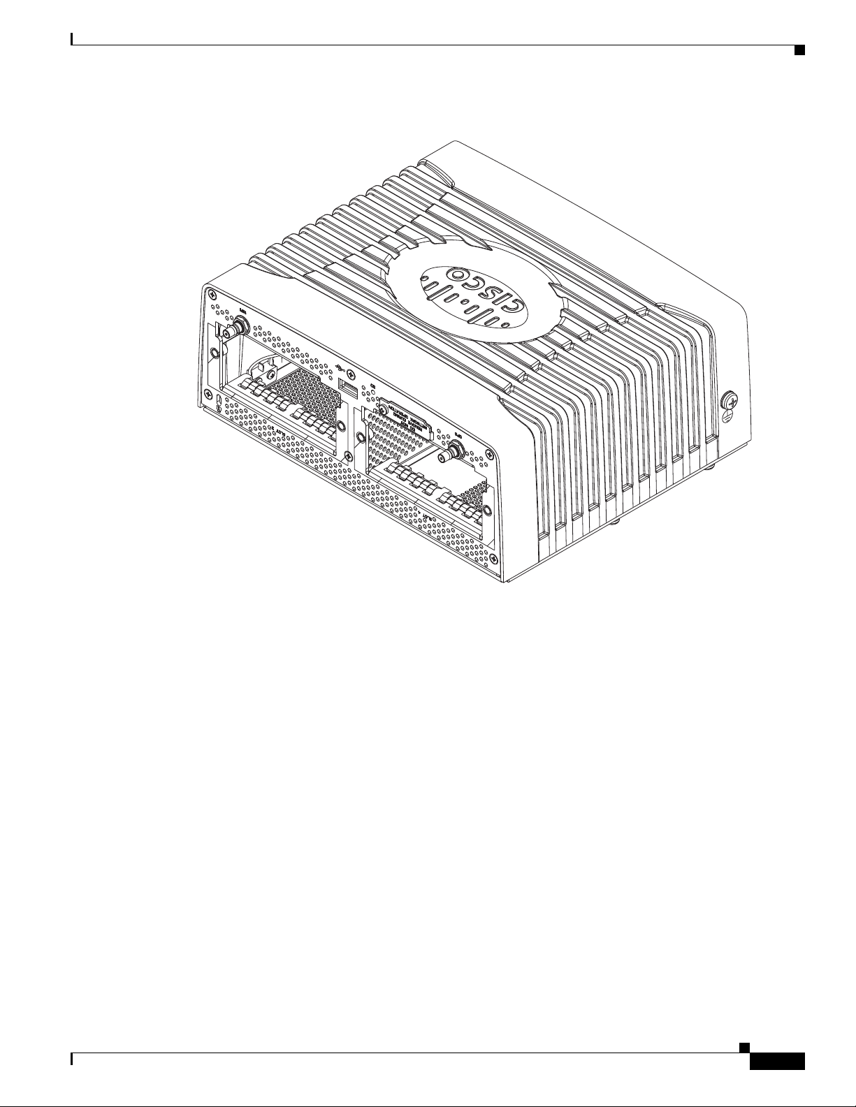
302204
Figure 3-1 Module Panel, Cisco 1120 Connected Grid Router
Router Overview
OL-26438-01
Cisco 1120 Connected Grid Router Hardware Installation Guide
3-3
Page 22
Hardware Features
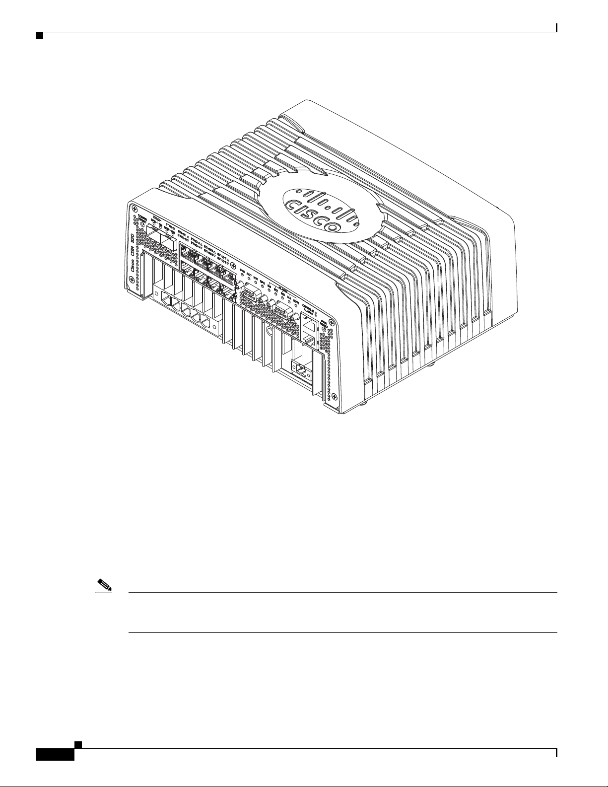
302205
Chapter 3 Router Hardware Description
Figure 3-2 Port Panel, Cisco 1120 Connected Grid Router
Hardware Features
This section illustrates and describes in detail the router hardware features, including mounting brackets,
network ports, device ports, and module slots.
Chassis
The router chassis is ruggedized to withstand harsh indoor operating environments, such as power
substations and utility boxes.
Note For a complete list of regulatory and compliance standards supported by the router, see the Regulatory
Compliance and Safety Information for the Cisco 1000 Series Routers document on Cisco.com at:
www.cisco.com/go/cgr1000-docs
Cisco 1120 Connected Grid Router Hardware Installation Guide
3-4
OL-26438-01
Page 23
Chapter 3 Router Hardware Description
302206
1
2
3
Table 3-1 Router Chassis Specifications
Specification Description
Dimensions 8.9 cm x 22.9 cm x 20 cm
Weight With 2 modules installed:
Operating temperature -25° C to +60° C (-25° F to 140 °F),
IP rating IP30
Mounting Features
The router ships with a single mounting kit, which supports the following mounting options:
Hardware Features
(3.5 in. x 9.0 in. x 7.8 in.)
8 pounds
(3.6 kg)
(Type test up to 85° C (185° F) for 16 hours)
• Mounting on a DIN rail, which is a standard interior mounting option for substation devices and
equipment. See Figure 3-3.
• Mounting on a wall, using the mounting keyholes on the mounting bracket.
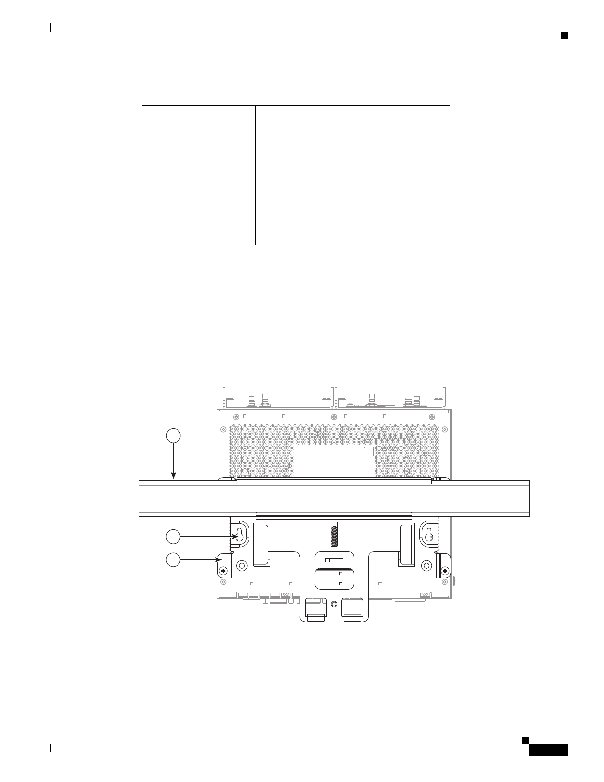
Figure 3-3 Mounting Features (Router Shown Mounted on a DIN Rail)
OL-26438-01
Cisco 1120 Connected Grid Router Hardware Installation Guide
3-5
Page 24
Hardware Features
Table 3-2 Mounting Features (Shown in Figure 3-3)
Item Feature Description
1 DIN rail Standard rail type used for mounting industrial control
2 Mounting keyhole (2) Use the mounting keyholes on the mounting bracket to mount the
3 Mounting bracket Included as part of the mounting kit. Use this bracket when
Mounting Procedures
For instructions on how to mount the router using the mounting bracket kit, see the chapter Mounting
the Router.
Module Panel (Front Panel) Features
Chapter 3 Router Hardware Description
equipment on an equipment rack.
router on a wall.
mounting the router on a wall or DIN rail.
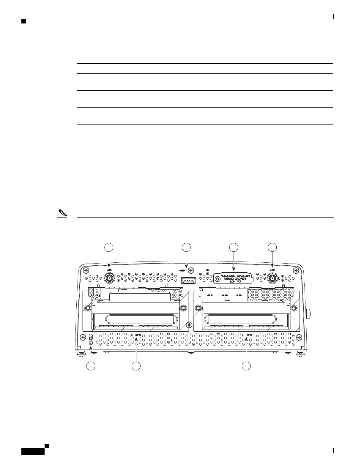
Figure 3-4 Module Panel (Front Panel) Features
Note The module panel labels appear inverted when the router rests on its base (see Figure 3-4). The label
orientation is designed to be read when the router is installed on a DIN rail.
1 2 3 4
302208
5 6 7
3-6
Cisco 1120 Connected Grid Router Hardware Installation Guide
OL-26438-01
Page 25
Chapter 3 Router Hardware Description
Hardware Features
Table 3-3 Module Panel (Front Panel) Features
Item Feature Description
1 WiFi antenna port Install a WiFi antenna (ordered separately) in this port to support the router
integrated Short-Range Access Point. For more information, see WiFi Antenna
Port, page 3-7.
2 USB port Connect this USB port to a supported, external USB device. For more information,
see USB Port, page 3-8.
3 SD Flash Memory module slot Contains an external flash memory card that stores the operating system software
image. For more information, see SD Flash Memory Module, page 3-8.
4 GPS antenna port Install a GPS antenna (ordered separately) in this port for connectivity to the router
GPS system. For more information, see GPS Antenna Port, page 3-9.
5 Kensington-compatible
security slot
6 CG Module slot 3 Install Cisco Connected Grid modules in the module slots. For more information,
7 CG Module slot 4
Provides security for the router by supporting Kensington or
Kensington-compatible locking security cables. For more information, see
Kensington-Compatible Security Slot, page 3-9.
see Connected Grid Module Slots, page 3-10.
Front Panel LEDs
WiFi Antenna Port
Antennas
Specifications
For detailed descriptions of the LEDs that appear on the front panel, see the chapter Router LED
Locations and States.
See Figure 3-4 for the WiFi antenna port location.
A single WiFi antenna is installed directly in this port to support the router Short-Range Access Point.
You must order this antenna separately from the router.
For more detailed information about supported antennas, including specifications and installation
instructions, see these documents:
• About Connected Grid Antennas chapter, in this guide
• Connected Grid Antennas Installation Guide on Cisco.com
Specification Description
Connector type
Supported antenna
Female QMA
Cisco Product ID (PID): ANT-4G-DP-IN-TNC
OL-26438-01
Form factor: Swivel-mount indoor dipole
Bands supported: Cellular/PCS/AWS/MDS, WiMAX 2100/2300/2500/2600 and
global GSM900/GSM1800/UMTS/LTE2600
Cisco 1120 Connected Grid Router Hardware Installation Guide
3-7
Page 26

Hardware Features
USB Port
USB Connections
Chapter 3 Router Hardware Description
See Figure 3-4 for the USB port location.
The router features one standard USB 2.0 port for connecting and powering an optional USB peripheral
device.
The USB port operates at the following speeds:
• 1Mbps
• 12 Mbps
• 480 Mbps
• Depending on the USB devices you connect to this port, you might require a USB extension cable
to connect devices.
• To prevent a connected USB device accidental or unauthorized removal from the port, secure any
connected USB device with a locking mechanism designed for this purpose. You must provide any
locking device or mechanism.
Specifications
Specification Description
USB Port Type Type A
USB Device Types Supported USB 1.1, USB 2.0
Power Output 2.5W (+5V +/-5% @ 500mA) per port
SD Flash Memory Module
The router supports one Cisco Secure Digital (SD) flash memory module (SD card), which stores router
software, configurations, and network data. For detailed information about the SD card, see the chapter
Using the SD Flash Memory Module.
Supported SD Cards
Table 3-4 lists the SD cards that the router supports.
Table 3-4 Supported SD Flash Modules
Size
2-GB flash memory module
3-8
Caution You must use a supported Cisco SD card with the router. Using an unsupported card could impact SD
card reliability and therefore router performance.
Cisco 1120 Connected Grid Router Hardware Installation Guide
OL-26438-01
Page 27
Chapter 3 Router Hardware Description
Caution Do not remove the SD card from the router; removing the SD card will cause the router to stop operating.
Specifications
Specification Description
Socket type 14 pin
Power (from router) +3.3 V
Voltage ramp rate range 1 mS to 100 mS
GPS Antenna Port
See Figure 3-4 for the GPS antenna port location.
You can connect a single Connected Grid GPS antenna using the 15-foot cable that is integrated into the
antenna. Mount the GPS antenna is mounted on the exterior of the substation or utility cabinet to enable
connectivity between the router and the GPS system.
Hardware Features
Supported Antennas
For more detailed information about supported antennas, including specifications and installation
instructions, see these documents:
• About Connected Grid Antennas chapter, in this guide
• Connected Grid Antennas Installation Guide on Cisco.com
Specifications
Specification Description
Connector type
Power consumption (from router)
Supported antenna
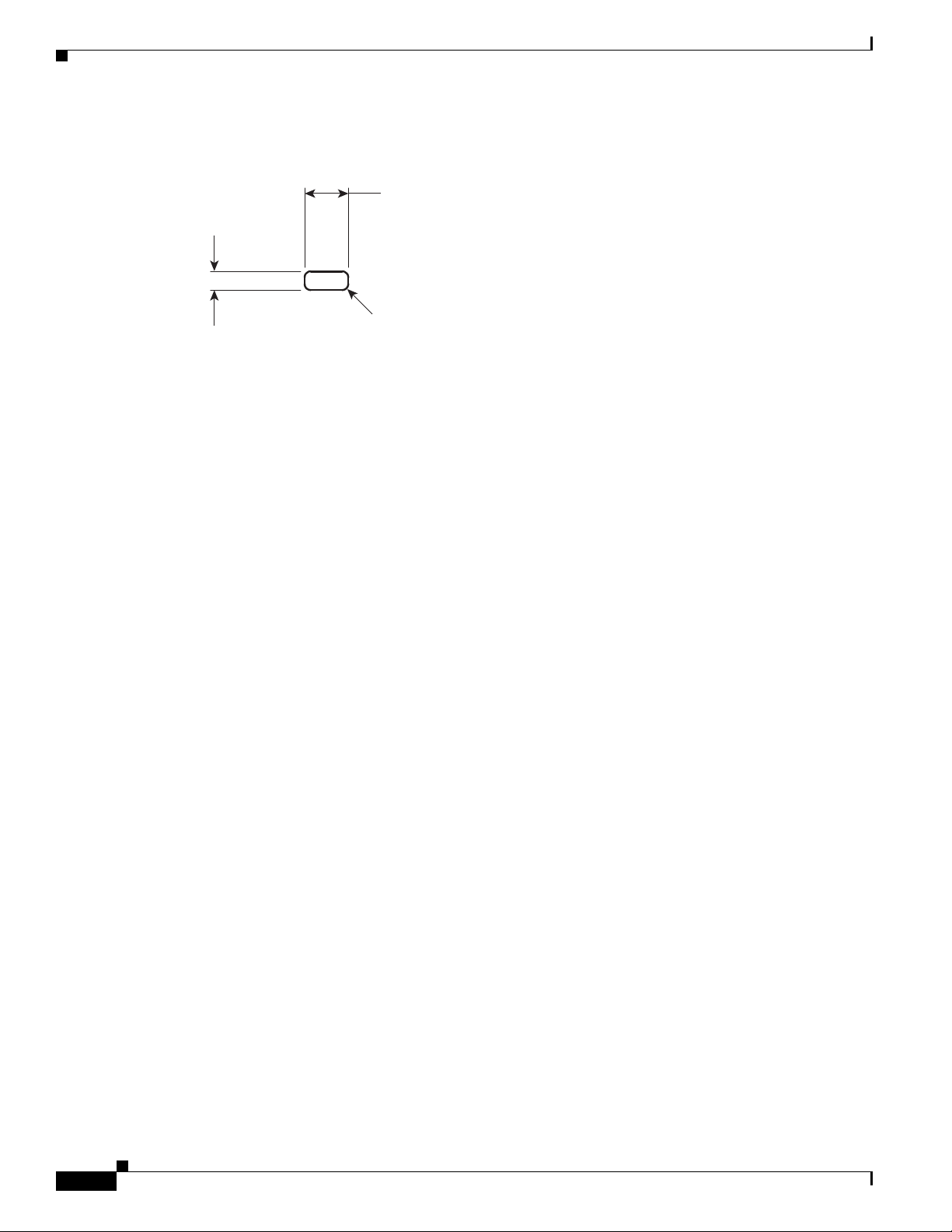
Kensington-Compatible Security Slot
See Figure 3-4 for the Kensington-compatible security slot location.
The front panel features one Kensington-compatible security slot. Use this slot to secure the router at the
installation location with a Kensington (or compatible) security cable.
Female QMA
3V (when GPS connectivity is active)
Cisco Product ID (PID): ANT-GPS-OUT-TNC
OL-26438-01
Cisco 1120 Connected Grid Router Hardware Installation Guide
3-9
Page 28
Hardware Features
302209
7.00
+.26
–.00
3.00
+.26
–.00
4 * R 1.00 max
Dimensions
Connected Grid Module Slots
The router has two module slots to support up to two compatible Cisco Connected Grid modules that add
NAN and LAN interfaces to the router.
• For more information about the Connected Grid modules for this router, see the chapter About
Connected Grid Modules.
Chapter 3 Router Hardware Description
Module Numbering
• For detailed installation instructions for installing Cisco Connected Grid modules in the router, see
the corresponding installation and configuration guide for each module at:
www.cisco.com/go/cg-modules
The router uses module numbering to identify the integrated and modular router components. Some
system software commands refer to the following module numbers.
• Module 1 is the integrated router supervisor engine (located on the CPU motherboard)
• Module 2 is the router integrated Ethernet switch module, which has six Fast Ethernet ports and two
Gigabit Ethernet ports.
• Module 3 and Module 4 are external, Connected Grid modules installed in the router module slots
with the corresponding numbers (see Figure 3-4).
3-10
Cisco 1120 Connected Grid Router Hardware Installation Guide
OL-26438-01
Page 29
Chapter 3 Router Hardware Description
302210
RESET
SPD
EN
SFP 0/1
SPD
EN
SFP 0/0
GE 0/1
GE 0/0
FE 0/5
FE 0/4
FE 0/3
FE 0/2
FE 0/1
FE 0/0
ALARM
OUT 1
IN 4
IN 3
IN 2
IN 1
GPS
WIFI
ACT
SYS
ALARM
CONSOLE
POWER
PE N L3 L2 L1
+
-
1 5 6
7 8 9
2 3 4
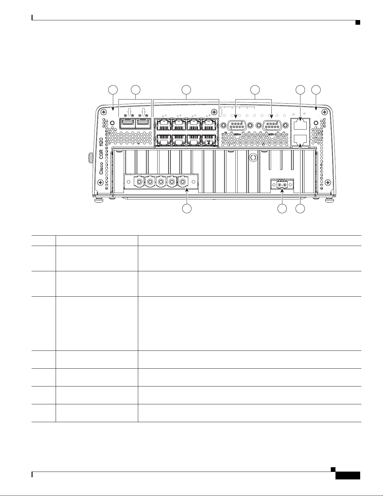
Cable Panel (Back Panel) Features
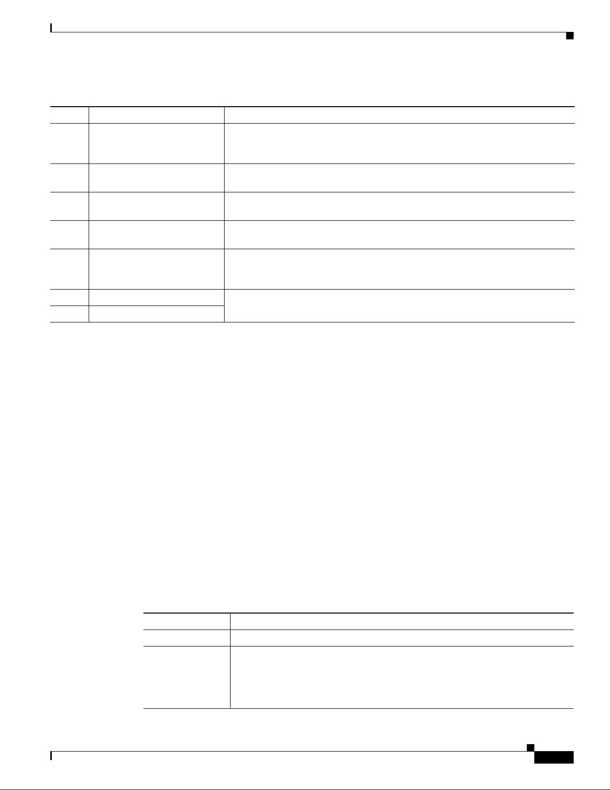
Figure 3-5 Cable Panel (Back Panel) Features
Hardware Features
Table 3-5 Cable Panel (Back Panel) Features
Item Feature Description
1 CONFIG Reset button Press for at least 5 seconds to return the router software configuration to the factory
default, and power cycle the router. For information on how to use this feature,
including a Caution statement, see CONFIG Reset Button, page 3-12.
2 SFP ports Install supported small-form-factor pluggable (SFP) modules in these two SFP ports,
labeled ETH 2/1 and ETH 2/2. For more information and supported SFPs, see Small
Form-Factor Pluggable (SFP) Ports, page 3-12.
3 Ethernet ports:
• 2–Gigabit Ethernet
(10/100/1000 Mbps)
• 6–Fast Ethernet
(10/100 Mbps)
Make network connections using the Ethernet ports. For more information, see
Ethernet Ports, page 3-13.
• Gigabit Ethernet (GE) ports—GE ports ETH 2/1 and ETH 2/2 are WAN ports
for connectivity to a primary substation or a control center.
• Fast Ethernet (FE) ports —FE ports ETH 2/3 to ETH2/8 are LAN ports for local
network devices.
4 Serial ports Connect the router to legacy devices using these two serial ports. For more
information on these ports and supported devices, see Serial Ports, page 3-15.
5 Console port Connect a console or PC to the asynchronous console port to manage the router with
a local connection.
6 PWR RESET button Press the PWR RESET button for at least 5 seconds to power cycle the router. For
more information on how to use this feature, see PWR RESET Button, page 3-12.
7 AC power supply connector Connect the router to the AC power supply (included). For more information, see AC
Power Supply, page 3-17.
OL-26438-01
Cisco 1120 Connected Grid Router Hardware Installation Guide
3-11
Page 30

Chapter 3 Router Hardware Description
Hardware Features
Table 3-5 Cable Panel (Back Panel) Features
8 DC power connector Connect an external backup battery unit (not included) to the router in the event that
the AC power fails. For more information, see DC Input for Battery Backup,
page 3-17.
9 Alarm port Connect this alarm port to an alarm system to monitor external events and trigger
alarms for external events. For more information, see Alarm Port, page 3-18.
Back Panel LEDs
For detailed descriptions of the LEDs that appear on the back panel, see the chapter Router LED
Locations and States.
CONFIG Reset Button
See Figure 3-5 for the CONFIG Reset button location.
Caution When you use the CONFIG Reset button to restore the router to the factory default software
configuration, the current software configuration is permanently deleted from the router.
Press the CONFIG Reset button for at least 5 seconds to return the router software configuration to the
factory default, and power cycle the router. Power cycling the router turns the router off, then
immediately back on. The router will temporarily stop operating on the network during the power cycle,
then resume operating when the power cycle process is complete.
PWR RESET Button
See Figure 3-5 for the PWR RESET button location.
Press the PWR RESET button for at least 5 seconds to power cycle the router. Power cycling the router
turns the router off, then immediately back on. The router will temporarily stop operating on the network
during the power cycle, then resume operating when power cycle process is complete.
Small Form-Factor Pluggable (SFP) Ports
The router features two fiber optical SFP ports that support optional Cisco rugged SFP modules for
Gigabit Ethernet connections. The ports are labeled as follows (see Figure 3-5):
• ETH 2/1
• ETH 2/2
Note Interfaces ETH 2/1 and ETH 2/2 are also used by the Gigabit Ethernet (GE) Ports. For more information
about how these ports are used together, see Combo Ports, page 3-15.
Hot Swapping SFP Modules
The SFP modules can be installed or removed while the router is on and operating normally.
Cisco 1120 Connected Grid Router Hardware Installation Guide
3-12
OL-26438-01
Page 31

Chapter 3 Router Hardware Description
Supported SFPs
Table 3-6 lists the supported SFP modules.
Note See the Cisco 1000 Series Connected Grid Routers Release Notes for the most recent information about
supported hardware and software.
Table 3-6 Supported SFP Modules
Cisco Product ID Description
GLC-SX-MM-RGD 1000BASE-SX short wavelength; rugged
GLC-LX-SM-RGD 1000BASE-LX/LH long wavelength; rugged
GLC-FE-100LX-RGD 100BASE-LX10 SFP
GLC-FE-100FX-RGD 100BASE-FX SFP
GLC-ZX-SM-RGD 1000BASE-ZX extended distance; rugged
Hardware Features
Specifications
Ethernet Ports
Ethernet Connections
Specification Description
Connector type
Copper Interface
Fiber
Pinouts
RJ-45
Full-duplex 10BASE-T, 100BASE-TX, 1000BASE-T
SFP modules:
• 1000 Mbps 8B/10B coding
• 100 Mbps 4B/5B coding.
See Connector and Cable Specifications
See Figure 3-5 for Ethernet port locations
The router supports the following Ethernet connection types:
• 1000BASE-T—1000 Mbps full-duplex transmission over a Category 5 or higher shielded
twisted-pair (UTP) cable. Supports the Ethernet maximum length of 328 feet (100 meters).
• 100BASE-T—100 Mbps full-duplex transmission over a Category 5 or higher shielded twisted-pair
(UTP) cable. Supports the Ethernet maximum length of 328 feet (100 meters).
OL-26438-01
• 10BASE-T—10 Mbps full-duplex transmission over a Category 5 or higher shielded twisted-pair
(UTP) cable. Supports the Ethernet maximum length of 328 feet (100 meters).
Cisco 1120 Connected Grid Router Hardware Installation Guide
3-13
Page 32

Hardware Features
Fast Ethernet (FE) Ports
Specifications
Chapter 3 Router Hardware Description
The router features six Fast Ethernet (FE) ports that can be connected to local network devices, such as
IEDs, sensors, and reclosers. The ports are labeled as follows:
• ETH 2/3
• ETH 2/4
• ETH 2/5
• ETH 2/6
• ETH 2/7
• ETH 2/8
Specification Description
Connector type
Cables
Interface speed
IEEE standard
Pinouts
RJ-45
Category 5 or higher
10BASE-T and 100BASE-TX
IEEE 802.3
See Connector and Cable Specifications
Gigabit Ethernet (GE) Ports
The router features two Gigabit Ethernet (GE) ports for a WAN connection to a primary substation or
control center. The ports are labeled as follows:
• ETH 2/1
• ETH 2/2
Note Interfaces ETH 2/1 and ETH 2/2 are also used by the Small Form-Factor Pluggable (SFP) Ports. For
more information about how these ports are used together, see Combo Ports, page 3-15.
The GE ports automatically detect the type of any connected cable (fiber or copper) and then switch to
the corresponding mode (fiber or copper). When both cables types are connected to the router, the first
cable that establishes a link is enabled.
Specifications
Specification Description
Connector type
Cables
Interface speed
Pinouts
RJ-45 (Copper mode)
Optical fiber
Category 5, 5e, 6 shielded twisted pair (STP)
10BASE-TX, 100BASE-TX, 1000BASE-T
See Connector and Cable Specifications
3-14
Cisco 1120 Connected Grid Router Hardware Installation Guide
OL-26438-01
Page 33

Chapter 3 Router Hardware Description
1 2
302207
Combo Ports
The two Gigabit Ethernet (GE) Ports and the two Small Form-Factor Pluggable (SFP) Ports are labeled
identically (ETH 2/1 and ETH 2/2) because the SFP and GE interfaces share physical ports on the router.
Only one instance of each interface (ETH 2/1 and ETH 2/2) can be in use at any time.
• GE ports: Copper GE connections
• SFP modules: Fiber optic GE connections
These ports automatically detect the type of any connected cable (fiber or copper) and then switch to the
corresponding mode (fiber or copper).
Note If connections are made to both interfaces of the same name (ETH 2/1 or ETH 2/2), the first connection
that establishes a link is the only connection enabled.
Figure 3-6 GE Ports and SFP Ports Share Interfaces ETH 2/1 and ETH 2/2
Hardware Features
Serial Ports
OL-26438-01
Items Description Gigabit Ethernet Connection Type
1 SFP module ports Fiber optic
2 Gigabit Ethernet ports Copper
See Figure 3-5 for serial port locations.
The router has two serial ports that support the following modes (selected with system software
commands):
• RS232
• RS485
Cisco 1120 Connected Grid Router Hardware Installation Guide
3-15
Page 34

Hardware Features
Specifications
Chapter 3 Router Hardware Description
The ports are labeled as follows:
• SER 1/1
• SER 1/2
Specification RS232 RS485
Connector type
Cable
Signaling
Max. drivers
Max. receivers
Operating mode
Network topology
Max. distance (standard)
Max speed
(at 12 m/1200 m)
Pinouts
DB-9
You must order a serial transition cable for the signaling protocol.
Single-ended Differential
132
1 256
Full duplex Half duplex
Full duplex
Point-to-point Multipoint
15 m 1200 m
20 Kbps/1 Kbps 35 Mbms/100 Kbps
See Connector and Cable Specifications
Console Port
Note The router also supports wireless console connections with an internal Short-Range Access Point.
See Figure 3-5 for the console port location.
The router features a single asynchronous console port for connecting a console or PC directly to the
router. To configure the router locally, using the command-line interface (CLI), you must establish a
connection to the router with a terminal session.
Console Port Default Settings
The console port does not support hardware flow control. The default settings for the port are:
9600 baud, 8 data bits, no parity, and 1 stop bit.
Connecting to the Console Port
Detailed information about connecting to the console port is in the chapter Making Network
Connections.
3-16
Cisco 1120 Connected Grid Router Hardware Installation Guide
OL-26438-01
Page 35

Chapter 3 Router Hardware Description
Specifications
Specification Description
Connector type RJ-45
Transceiver RS-232
Cable type EIA RJ-45
Pinout See Connector and Cable Specifications
AC Power Supply
See Figure 3-5 for the AC power connection location.
The AC power supply connector on the router cable-side (back) panel is the connection to the to AC
power terminal block. The router supports single-phase and three-phase AC power input.
For detailed information about the AC power supply, including how to connect the router to AC power,
see the chapter Connecting the Router to Power.
Hardware Features
DC Input for Battery Backup
See Figure 3-5 for the external DC power input connector.
The router supports an external battery backup DC power connection. You must provide the battery
backup connection or unit.
For detailed information about the DC power input, including how to connect the router to a DC power
input source, see the chapter Connecting the Router to Power.
Power Specifications
Specification Description
DC Input Voltage Nominal operating range: 10.6 to 52VDC
AC Input Voltage Three-phase
Maximum operating range: 9 to 60VDC
• 208 to 415VAC 4W+ PE WYE
Single-phase
• 100 to 240VAC @ 50/60Hz
OL-26438-01
Cisco 1120 Connected Grid Router Hardware Installation Guide
3-17
Page 36

Hardware Features
Chapter 3 Router Hardware Description
Circuit Breaker AC
• Single Phase: Single 10A circuit breaker
• Three-phase: Three 10A ganged circuit breaker
• AC voltage rating: 250VAC L-N (minimum)
Note We recommend that the circuit breaker be installed in close
proximity to the router by a licensed electrician in accordance
with local electrical standards.
DC
• DC rating: 60VDC minimum, 10A maximum
Output Power 40W
Cooling Type Natural convection
Operating Temperature -40 F to 140 C (-40 C to 60 C)
Lifetime 20 years, at 104 F (40 C)
Alarm Port
See Figure 3-5 for the alarm port location.
Attach the alarm port to an alarm system to monitor and trigger external alarm events. The router
supports two alarm inputs and two alarm outputs.
The alarm-trigger setting determines when an alarm is sent to the attached alarm system.
The alarm port has a rating of 30V DC, 1A.
Input Alarm Trigger Settings
• Open—The open setting indicates that the normal router operating condition has an electrical
current passing through the alarm circuits (DRY contact closed). If this electrical current is no
longer detected (DRY contact open), an alarm is generated.
• Closed—The closed setting indicates that the normal router operating condition is that no electrical
current is passing through the alarm circuits (DRY contact open). If an electrical current is detected
(DRY contact closed), an alarm is generated.
Output Alarm Trigger Settings
• Normally Open (NO)—This setting depends on the pinout of the cable that is connected to the
alarm port. See the appendix Connector and Cable Specifications for details.
• Normally Closed (NC)—This setting depends on the pinout of the cable that is connected to the
alarm port. See the appendix Connector and Cable Specifications for details.
3-18
If interfaces fail or other non-fatal errors occur, the alarm port does not respond. Continue to use SNMP
to manage these types of errors.
Note Due to the RJ-45 pin spacing, the alarm port does not support AC signaling.
Cisco 1120 Connected Grid Router Hardware Installation Guide
OL-26438-01
Page 37

Chapter 3 Router Hardware Description
Specifications
Specification Description
Connector type
Alarm input
Alarm output
RJ-45
8volts @ 1mA
30 volts @ 1 A
Internal Hardware Features
This section describes router hardware features that are integrated into the router and which are not
visible from the router exterior. This section describes the following features:
• Memory, page 3-19
• Internal GPS Module, page 3-19
• Short-Range Access Point, page 3-20
Hardware Features
• Real-Time Clock (RTC), page 3-21
• Temperature Sensor, page 3-21
Memory
This router supports the three types of memory described in this section.
• SD Flash Memory Module–See the chapter Using the SD Flash Memory Module for information
• DDR2 SDRAM–The router features 1 GB of double data rate (DDR2) SDRAM.
• Boot Flash–The router features 16 MB of boot flash memory, consisting of two 8 MB Serial
Internal GPS Module
The router has an internal Global Positioning System (GPS), which provides precise time and location
location information to the system.
GPS LED
You can view the GPS LED to determine the GPS state and whether or not it is successfully connected
to a GPS satellite. For information on the GPS LED, see the chapter Router LED Locations and States.
about the router SD card, which stores the router configuration and system data.
Peripheral Interface (SPI) flash devices. The boot flash supports the Common Flash Interface (CFI)
standard.
OL-26438-01
Cisco 1120 Connected Grid Router Hardware Installation Guide
3-19
Page 38

Hardware Features
Specifications
Related Commands
Chapter 3 Router Hardware Description
Specification Description
Channels
Tracking sensitivity
Acquisition sensitivity
Fast TTFF (Cold start)
Error correction
Use the commands in this section to see the GPS current time and location.
Use the show gps time command to display the current GPS time:
cgr-1000# show gps time
8:46:9.923 UTC Fri Sep 11 2011
12
-160 dBm
-148 dBm
38 sections
Space Based Augmentation Systems (SBAS)
Use the show gps location command to display the GPS latitude and longitude:
cgr-1000# show gps location
Latitude: 37.4090637
Longitude -121.9523598
Short-Range Access Point
The router features an integrated, short-range WiFi access point to support a wireless connection to the
router, over which you can administer the router. The router can be installed in a utility box or substation;
the wireless connection enables you to manage the router from outside these enclosures.
The WiFi connection is available only when the system software is operating. If the system software is
not operating, you cannot use the WiFi connection to connect to or administer the router.
Related Commands
To display WiFi configuration information, enter any or all of the following commands:
• show interface wifi slot/port [associations | brief | description | statistics]–Summarizes the status
of the interface as up or down, the five second input and output rate and the number of input and
output packets. Additionally, the Cisco CG-OS router displays hardware details such as radio type
(802.11N, 2.4 GHz radio), MAC address and MTU setting.
• show controller wifi slot/port–Displays serial number, software version, and configured frequency
and power settings
For detailed information about these commands, see the chapter “Configuring the WiFi Interface” in the
Cisco 1000 Series Connected Grid Routers WiFi Software Configuration Guide, at
www.cisco.com/go/cgr1000-docs.
3-20
Cisco 1120 Connected Grid Router Hardware Installation Guide
OL-26438-01
Page 39

Chapter 3 Router Hardware Description
Real-Time Clock (RTC)
The router features an integrated real-time clock (RTC) with battery backup that supplies the system
software with accurate date and time information. The integrated router GPS compares the current RTC
time with the time at which it last received a valid signal to ensure accurate timekeeping on the router.
When the router is powered on using the CONFIG Reset Button, the RTC sets the router memory
controller and clock frequency.
RTC Battery
The RTC includes battery backup for the date and time when the router is not receiving any power.
Specifications
Specification Description
Battery type
Battery life span
Supported interrupts
Hardware Features
High-capacity lithium (550 mAh)
10 years
Time-of-day alarms (Range: 1/second – 1/month)
Periodic rates (Range: 122 us – 500 ms)
End-of-update-cycle notifications
Temperature Sensor
The router hardware features an internal temperature sensor used by the router software to monitor the
system operating temperature. The router can be configured to generate alerts when the temperature falls
outside of a user-defined temperature range. The router can also be configured to store historical
temperature data.
For more information about monitoring and storing router temperature data, see the Cisco 1000 Series
Connected Grid Routers Software Configuration Guide Set.
OL-26438-01
Cisco 1120 Connected Grid Router Hardware Installation Guide
3-21
Page 40

Hardware Features
Chapter 3 Router Hardware Description
3-22
Cisco 1120 Connected Grid Router Hardware Installation Guide
OL-26438-01
Page 41

Mounting the Router
This chapter describes the safety information, equipment, and procedures required to mount the
Cisco 1120 Connected Grid Router on a vertical pole or streetlight. This chapter contains these sections
• Router Mounting Kit, page 4-1
• Prepare to Mount the Router, page 4-2
• Mounting Instructions, page 4-4
• Ground the Router, page 4-8
Router Mounting Kit
The router ships with a mounting kit that contains all the parts required to mount the router on a DIN
rail or on a wall. The Mounting Kit Contents section includes a detailed description of the mounting parts
shipped with your router.
CHA PTER
4
Mounting Kit Contents
The mounting bracket attaches to the router. The router is then installed on a wall using the mounting
bracket, or on a DIN rail, using the DIN rail adapter.
OL-26438-01
Cisco 1120 Connected Grid Router Hardware Installation Guide
4-1
Page 42

Prepare to Mount the Router
Included Hardware
Qty 4 Qty 4 Qty 1
1
2 3 4
302214
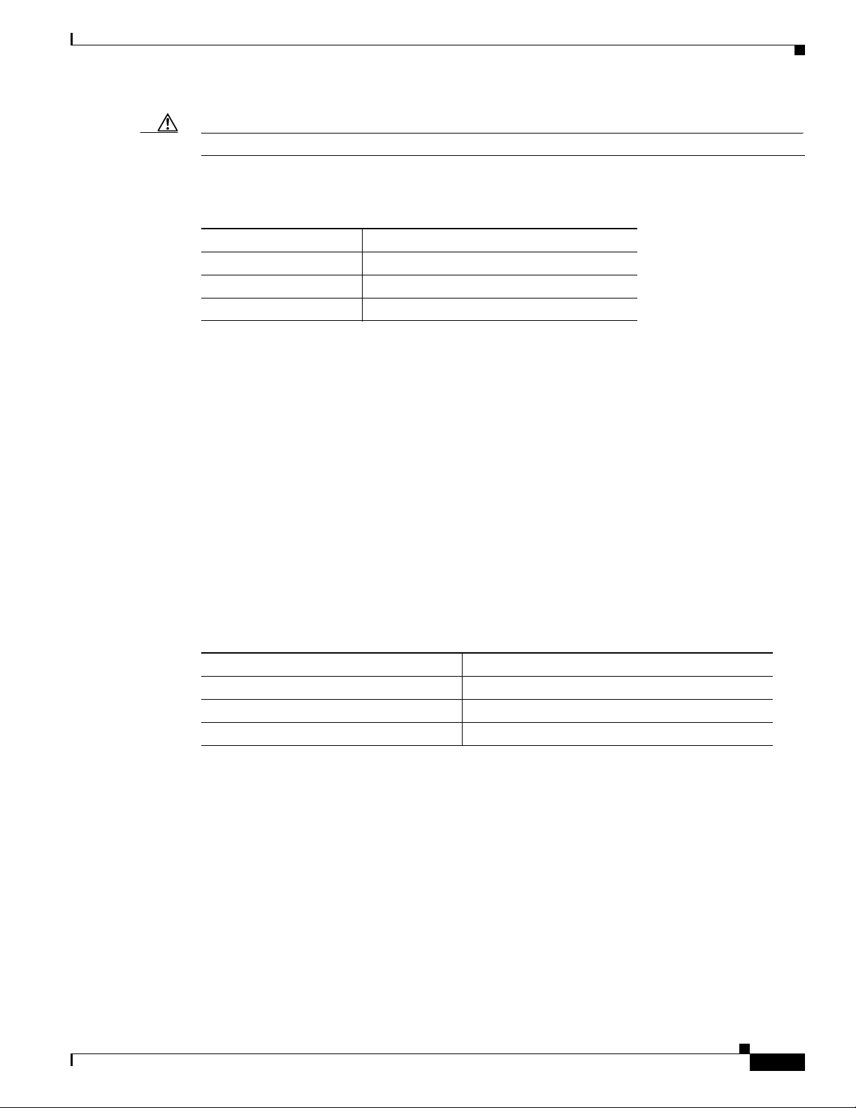
Figure 4-1 Mounting Kit Contents
Chapter 4 Mounting the Router
Item Description Qty.
1 Mounting bracket 1
2 Split lock washer (M8) 4
3 Nut (M8) 4
4 Mounting stud (M8) 1
Prepare to Mount the Router
Read the topics in this section before mounting the router:
• Materials and Tools You Supply, page 4-3
• Router Orientation When Mounting, page 4-3
• General Safety Information for Mounting, page 4-3
Cisco 1120 Connected Grid Router Hardware Installation Guide
4-2
OL-26438-01
Page 43

Chapter 4 Mounting the Router
Materials and Tools You Supply
You must supply some or all of these items to mount the router on a pole. The items you supply depend
on the installation procedure that you use.
Item Required for These Procedures
#2 Phillips screwdriver Attach the Mounting Bracket to the Router
Ground the Router
Crimping tool or pliers Ground the Router
Router Orientation When Mounting
When mounting the router on a DIN rail or wall, ensure that the router is oriented with the chassis
cabling openings pointing down so the router cable hangs down.
Prepare to Mount the Router
Caution Mounting the router with the cable panel at the top (facing up) can cause stress on the cables and
potentially impact network and other connections. Cisco discourages mounting the router with the cable
panel at the top.
General Safety Information for Mounting
Before performing any of the tasks in this chapter, read the safety warnings in this section and in the
Installation Safety and Site Preparation chapter.
One person is required to properly and safely mount the router.
Caution All mounting methods at any location are subject to the acceptance of local jurisdiction.
Caution Personnel mounting the router must understand grounding methods.
Warning
Do not locate the antenna near overhead power lines or other electric light or power circuits, or
where it can come into contact with such circuits. When installing the antenna, take extreme care
not to come into contact with such circuits, as they may cause serious injury or death. For proper
installation and grounding of the antenna, please refer to national and local codes (for example,
U.S.:NFPA 70, National Electrical Code, Article 810, Canada: Canadian Electrical Code, Section 54).
Statement 1052
OL-26438-01
Cisco 1120 Connected Grid Router Hardware Installation Guide
4-3
Page 44

Mounting Instructions
302212
Module Panel
Cable Panel
1 1
Mounting Instructions
This section includes all the steps required to mount the router on a wall or DIN rail. There are two main
procedures for mounting the router:
1. Attach the Mounting Bracket to the Router, page 4-4
2. Mount the Router on a DIN Rail, page 4-6
In some environments, you might want to mount the router on a wall instead of DIN rail. The wall
mounting procedure is described in Mount the Router on a Wall, page 4-7.
Attach the Mounting Bracket to the Router
Before you begin, disconnect the router from power and any network connections.
Step 1 Place the router on a stable surface, with the base of the router facing up and the module panel at the top,
as shown in Figure 4-2.
Step 2 Use the #2 Phillips screwdriver to remove the four large screws (Item 1, Figure 4-2) from the chassis
base. Keep the screws. You will replace them at the end of this procedure to mount the bracket on the
chassis.
Step 3 Remove only the screws indicated in Figure 4-2. Do not remove the smaller screws, which secure the
router bottom panel to the chassis.
Chapter 4 Mounting the Router
Figure 4-2 Remove the Four Large Screws (1) from the Router Base
4-4
Cisco 1120 Connected Grid Router Hardware Installation Guide
OL-26438-01
Page 45

Chapter 4 Mounting the Router
302211
1
2
3
Step 4 Place the mounting bracket onto the back of the router, following these guidelines, shown in Figure 4-3:
• The bracket handle (Item 3, Figure 4-3 ) should be facing the router cable panel.
• Align the bracket mounting holes (Item 2, Figure 4-3) with the router bracket connectors (Item 1,
Figure 4-3 Align the Bracket Mounting Holes (2) over the Router Bracket Connectors (3)
Mounting Instructions
Figure 4-3). (The screws were removed from the bracket connectors in Step 2.)
Step 5
Step 6 Evenly hand-tighten the screws (Item 1 in Figure 4-4), then tighten with the Phillips #2 screwdriver.
Replace the screws you removed in Step 2 to secure the mounting bracket to the chassis.
Cisco 1120 Connected Grid Router Hardware Installation Guide
OL-26438-01
4-5
Page 46

Mounting Instructions
302212
1
Chapter 4 Mounting the Router
Figure 4-4 Replace and Tighten Screws to Secure Bracket to Router
Mount the Router on a DIN Rail
The steps in this section assume that your substation or utility box already has a DIN rail installed and
ready to support equipment. If your environment does not use DIN rails, you can Mount the Router on
a Wall, page 4-7.
To mount the router on a DIN rail:
Step 1 Tilt the chassis-bracket assembly about 10 to 30 degrees and the bracket handle facing down. Do not
mount the router with the bracket handle facing up.
Step 2 Place the top lip of the bracket (Item 2 in Figure 4-5) over the top of the DIN rail (Item 3 in
Figure 4-5).
Step 3 Firmly pull the bracket handle (Item 1 in Figure 4-5) down and rotate the unit until it is parallel to the
wall or DIN rail.
Caution Use caution when pulling the bracket handle: The handle is spring-loaded and will snap shut when
released quickly.
Step 4 Slowly release the bracket handle so that the bottom lip of bracket is secured over the top of the DIN rail.
4-6
Cisco 1120 Connected Grid Router Hardware Installation Guide
OL-26438-01
Page 47

Chapter 4 Mounting the Router
Figure 4-5 Router Mounted on DIN Rail (3)
Mounting Instructions
3
2
Mount the Router on a Wall
The mounting bracket has wall-mount holes that you can use to mount the router directly on a wall.
To mount the router on a wall, you must provide the hardware that can be used with the wall material in
the installation environment.
Caution The wall material and hardware that you use to mount the router must be able to support the weight of
the router with two modules installed: 8.0 pounds (3.6 Kg).
Wall-Mount Orientation
See Router Orientation When Mounting, page 4-3.
OL-26438-01
1
302215
Cisco 1120 Connected Grid Router Hardware Installation Guide
4-7
Page 48

Ground the Router
302217
7.30 inches
(185.4 mm)
y
1
Chapter 4 Mounting the Router
Wall-Mount Location
Identify an area on a wall that meets the safety, space, and environmental requirements described in the
chapter Installation Safety and Site Preparation.
Wall-Mount Height
The router should be mounted at a height at which you are able to view the top of the module-side panel
and at which the cables are able to be managed without adding stress to the router ports.
Wall-Mount Hardware Distance
The hardware you provide should be mounted the correct distance apart so that the router wall mount
holes (Item 1, Figure 4-6) can be hung on the hardware 7.30 inches (185.4 mm).
Figure 4-6 Distance for Wall-Mounting Hardware
Ground the Router
You must ground the router with the grounding lug on the chassis exterior as described in this section.
Warning
This equipment must be grounded. Never defeat the ground conductor or operate the equipment in the
absence of a suitably installed ground conductor. Contact the appropriate electrical inspection
authority or an electrician if you are uncertain that suitable grounding is available.
Cisco 1120 Connected Grid Router Hardware Installation Guide
4-8
Statement 1024
OL-26438-01
Page 49

Chapter 4 Mounting the Router
302213
Figure 4-7 Router Grounding Lug Location
Ground the Router
To ground the router, follow these steps:
Step 1 Use the appropriate crimping tool or pliers to crimp a 6-gauge ground that will attach to the grounding
lug on the router exterior. You must provide the wire.
Figure 4-6 shows the grounding lug location.
Step 2 Connect the other end of the wire to the router grounding connectors, using the supplied grounding
screws. Tighten the grounding screws to 10 to 12 foot-pounds of torque. Do not overtighten!
Step 3 If necessary, strip the other end of the ground wire and connect it to a reliable earth ground, such as a
grounding rod or an appropriate grounding point on substation equipment that is grounded.
OL-26438-01
Cisco 1120 Connected Grid Router Hardware Installation Guide
4-9
Page 50

Ground the Router
Chapter 4 Mounting the Router
4-10
Cisco 1120 Connected Grid Router Hardware Installation Guide
OL-26438-01
Page 51

Connecting the Router to Power
This chapter describes how to connect the Cisco 1120 Connected Grid Router to AC and DC power
source, and includes the following sections:
• Before You Begin, page 5-1
• AC Power Connection Information, page 5-4
• Connect to AC Power, page 5-7
• Connect to DC Power (Optional), page 5-9
• Power Cycling the Router, page 5-10
Before You Begin
Before you connect power to the router, read the following topics in this section:
CHA PTER
5
• Verify Router Hardware Readiness, page 5-1
• Tools and Materials You Supply, page 5-2
• EMC Class A Notices and Warnings (US and Canada), page 5-2
• Safety Information, page 5-3
Verify Router Hardware Readiness
Before connecting the router to power, verify the following:
• The unit is grounded as described in the chapter Mounting the Router
• The SD flash memory module is installed correctly as described in the chapter Using the SD Flash
Memory Module
OL-26438-01
Cisco 1120 Connected Grid Router Hardware Installation Guide
5-1
Page 52

Before You Begin
Tools and Materials You Supply
You must provide the following tools and materials to connect the router to AC power or optional DC
power:
• Wire-stripping tool
• Flat-blade screwdriver
• AC power cable that meets the following requirements:
–
Wiring compatible with the power supply used at your site: single-phase or three-phase, rated
10A minimum
–
Plug that is compatible with the power source used at your site: single-phase or three-phase.
–
Correct length for your installation
• DC power cable that meets the following requirements:
–
The length and gauge of the DC power cable must be selected such that the voltage supplied to
the terminals of the router does not drop below 10.6VDC, which is the minimum recommended
operating voltage. See the Power Specifications section in the Router Hardware Description
chapter.
–
The maximum input current at 9VDC input will be less than 7A and the wire size must be
selected by considering the installation DC operating voltage. DC input on the router
accommodates a 12AWG to 18AWG wire size.
Chapter 5 Connecting the Router to Power
–
Please consult your Cisco reseller, partner, or sales representative for unusual installation
requirements of greater than 30 feet of cabling.
EMC Class A Notices and Warnings (US and Canada)
Tip For a complete listing of all EMC Class A Notices and Warnings, refer to following document:
Regulatory Compliance and Safety Information for the Cisco 1000 Series Connected Grid Routers
Class A Notice for FCC
Modifying the equipment without Cisco's authorization may result in the equipment no longer
complying with FCC requirements for Class A digital devices. In that event, your right to use the
equipment may be limited by FCC regulations, and you may be required to correct any interference to
radio or television communications at your own expense.
This equipment has been tested and found to comply with the limits for a Class A digital device, pursuant
to Part 15 of the FCC Rules. These limits are designed to provide reasonable protection against harmful
interference when the equipment is operated in a commercial environment. This equipment generates,
uses, and can radiate radio frequency energy and, if not installed and used in accordance with the
instruction manual, may cause harmful interference to radio communications. Operation of this
equipment in a residential area is likely to cause harmful interference in which case users will be
required to correct the interference at their own expense.
5-2
Changes or modifications not expressly approved by the party responsible for compliance could void the
user's authority to operate the equipment.
Cisco 1120 Connected Grid Router Hardware Installation Guide
OL-26438-01
Page 53

Chapter 5 Connecting the Router to Power
Class A Notice for Canada
This Class A digital apparatus complies with Canadian ICES-003.
Cet appareil numérique de la classe A est conforme à la norme NMB-003 du Canada.
This device complies with Industry Canada (IC) license-exempt RSS standard(s). Operation is subject
to the following two conditions: (1) this device may not cause interference, and (2) this device must
accept any interference, including interference that may cause undesired operation of the device.
Safety Information
When connecting the router to AC power, you must ensure that the following conditions are met:
• AC power is available at the installation location.
• AC power can be readily and conveniently removed from the router. The power should not be
removed by disconnecting the AC power connector on the unit.
Before You Begin
Warning
Warning
Warning
Caution Before connecting or disconnecting the power cord, you must remove AC power from the power cord
The plug-socket combination must be accessible at all times, because it serves as the main
disconnecting device.
Only trained and qualified personnel should be allowed to install, replace, or service this equipment.
Statement 1030
Installation of the equipment must comply with local and national electrical codes.
Statement 1019
Statement 1074
using a suitable service disconnect.
• When you install the unit outdoors, or in a wet or damp location, the AC branch circuit that powers
the unit should have ground fault protection (GFCI), as required by Article 210 of the NEC.
• Ensure that the user-supplied AC power plug is certified for outdoor use and has a minimum IP67
rating, such as Interpower 84131251 or Hubbell HBL316P6W (IEC/EN60309 pin-and-sleeve type
connectors).
• If the power cord goes through a metal cover, a bushing should be installed to prevent fraying of the
cord. When using a strain relief bushing, you should follow these recommendations:
–
Use properly sized parts that are suitable for outdoor installation
OL-26438-01
–
Use bushings that are safety certified
Cisco 1120 Connected Grid Router Hardware Installation Guide
5-3
Page 54

AC Power Connection Information
302222
1 2
AC Power Connection Information
This section provides information you need to connect the router to AC power and includes the following
topics:
• Router Power Source Input Terminals, page 5-4
• Electrical Wire Color Codes, page 5-5
• Terminal Blocks and Mating Connectors for Power Input Wiring, page 5-6
Router Power Source Input Terminals
The Cisco CGR 1120 Router has two sets of terminals for power input (see Figure 5-1):
• A set of five terminals for AC-input power source wires
• A set of two terminals for DC-input power source wires
Figure 5-1 Router Power Source Input Terminals
Chapter 5 Connecting the Router to Power
5-4
Figure 5-1 shows the label for each terminal.
Cisco 1120 Connected Grid Router Hardware Installation Guide
OL-26438-01
Page 55

Chapter 5 Connecting the Router to Power
Table 5-1 Power Input Terminals
Item Terminal Type Description
1 AC-Input Power Source Terminals
N
L3
L2
L1
2 DC-Input Power Source Terminals
–
+
AC Power Connection Information
Ground terminal
To provide a protected earth
ground, terminate either a
green/yellow or green wire
(region-specific) from the AC
power cable on the external screw
on the left side of the router.
See Tab le 5-2 for details on wiring
colors by region
Neutral wire terminal
Line terminal
Line terminal
Line terminal
Negative
Positive
Electrical Wire Color Codes
This section provides general information about the standard wire coloring used for AC and DC power
connections. Use these colors as a guide when wiring the terminal block as part of the AC power and DC
power connection procedure.
Caution You should verify power wire color information for your installation site with a qualified electrician
before making any power connections to the router.
Table 5-2 AC Power Electrical Wiring Colors by Region
Region or Country Standard
European Union
United States
Canada
Ground
(Protective Earth) Neutral Line (Phases)
IEC 60446 Green-and-yellow Blue Black, brown, gray
– Green White 120/208/240V: Black, red, blue
277/480V: Brown, orange, yellow
– Green White 120/208/240V: Red, black
Single-phase isolated systems:
orange, brown
Three-phase isolated systems:
orange, brown, yellow
OL-26438-01
Cisco 1120 Connected Grid Router Hardware Installation Guide
5-5
Page 56

Chapter 5 Connecting the Router to Power
302218
1
2
3
AC Power Connection Information
Table 5-3 DC Power Electrical Wiring Colors
Color Description
Black
Red
Negative
Positive
Terminal Blocks and Mating Connectors for Power Input Wiring
The router ships with two power terminal blocks that are used to connect power input wires to the power
input mating connectors on the router.
• Figure 5-2 shows the AC-input terminal block.
• Figure 5-3 show the DC-input terminal block.
.
Figure 5-2 AC-Input Terminal Block
Item Description Quantity
1
Captive screws, for connecting terminal block to mating connector on the router 2
2
Terminal openings for inserting AC-input source wires 5
3
Screws for tightening wires into terminal openings 5
Cisco 1120 Connected Grid Router Hardware Installation Guide
5-6
OL-26438-01
Page 57

Chapter 5 Connecting the Router to Power
302219
1 2
3
302221
Figure 5-3 DC-Input Terminal Block
Connect to AC Power
Item Description Quantity
1
Terminal openings for inserting DC-input source wires 2
2
Captive screws, for connecting terminal block to mating connector on the router 2
3
Screws for tightening wires into terminal openings 2
Figure 5-4 Terminal Block Mating Connectors on Router Chassis
Connect to AC Power
This section describes how to make two the following types of AC power connections to the router:
• Single-phase AC
• Three-phase AC
OL-26438-01
Cisco 1120 Connected Grid Router Hardware Installation Guide
5-7
Page 58

Connect to AC Power
3-Phase AC Power
Single-Phase AC Power
302223
1
2 3
1
2 34
5
Note The router will power on as soon as it is connected to an AC power source. You are not required to press
Caution When connecting the router AC power connector, always connect the router end of the cable first. When
Step 1 Turn off power to the AC power source at the designated circuits.
Step 2 Use a wire-stripping tool to strip each of the wires from the AC-input power source. Expose the wire to
Chapter 5 Connecting the Router to Power
To connect the router to AC power, follow these steps:
a power button to power on the router.
removing the AC power connector, always disconnect the router end of the cable last.
the appropriate length for the terminal block, about 0.25 inches.
Step 3 Insert the wires into the terminal block openings that correspond to the labeled AC terminals shown in
Figure 5-1 and described in Tabl e 5- 1 .
Insert wires that correspond to your installation (three-phase or single-phase), as shown here:
Step 4 After the wires are inserted in the terminal block, use the screwdriver to tighten the terminal block wire
screws to keep the wires in place. The screws are shown in Figure 5-2.
Step 5 Taking care not to place strain on the wires, insert the terminal block into the mating connector on the
router. The mating connector is shown in Figure 5-4.
Step 6 Use the screwdriver to tighten the two captive screws on the terminal block to the mating connector. The
terminal screws are shown in Figure 5-2. Torque the terminal block screws to 11 lbf-in.
Step 7 Turn on AC power by plugging in an AC power cord to the power source, or enabling power at the
designated circuit. The router will power on and run a series of bootup tests, indicated by blinking LEDs.
5-8
Cisco 1120 Connected Grid Router Hardware Installation Guide
OL-26438-01
Page 59

Chapter 5 Connecting the Router to Power
Verify AC Power Connection
After you connect the router to AC power, verify that the power is being supplied to the router by
checking the status of the SYS (System) LED. As the router starts up, the SYS LED will show these
states:
Sequence State Description
1 Yellow System is receiving power.
2 Green blinking The system is starting up or power cycling, and loading system
software, including BIOS and operating system.
3 Green solid The system is functioning normally.
For the SYS LED location, see Figure 10-1 in the chapter Router LED Locations and States.
Connect to DC Power (Optional)
Connect to DC Power (Optional)
You can connect the router to a DC power source that provides backup power to the router in cases when
AC power is disrupted or fails. You must provide the DC power source and ensure that it is compliant
with the installation site requirements.
To connect a DC-input power source to the router, follow these steps:
Step 1 Turn off power to the DC power source at the designated circuits.
Step 2 Using a wire-stripping tool to strip both of the wires from the DC-input power source. Expose the wire
to the appropriate length for the terminal block, about 0.25 inches.
Step 3 Insert the wires into the terminal block openings that correspond to the labeled DC terminals shown in
Figure 5-1 and described in Tabl e 5- 1 .
Make sure to match the polarity (negative-to-negative and positive-to-positive) when you connect the
wires to the terminal block openings:
OL-26438-01
Cisco 1120 Connected Grid Router Hardware Installation Guide
5-9
Page 60

Power Cycling the Router
302220
Chapter 5 Connecting the Router to Power
Step 4 After the wires are inserted in the terminal block, use the screwdriver to tighten the terminal block wire
screws to keep the wires in place. The screws are shown in Figure 5-2.
Step 5 Taking care not to place strain on the wires, insert the terminal block into the mating connector on the
router. The mating connector is shown in Figure 5-4.
Step 6 Use the screwdriver to tighten the two captive screws on the terminal block to the mating connector. The
terminal screws are shown in Figure 5-2. Torque the terminal block screws to 11 lbf-in.
Step 7 Enable DC power by plugging in the DC power supply cord to the power source, or by enabling power
at the designated circuit.
Power Cycling the Router
There are two reset buttons on the router cable panel, which can be used to power cycle the router and
to reset the router system software to the default configuration. Use the reset buttons as described in this
section.
Caution When you use the CONFIG Reset button to restore the router to the factory default software
configuration, the current software configuration is permanently deleted from the router.
Accessing the Buttons
You must provide a pin, paper clip, or other thin metal tool to access and press these buttons.
Cisco 1120 Connected Grid Router Hardware Installation Guide
5-10
OL-26438-01
Page 61

Chapter 5 Connecting the Router to Power
RESET
SPD
EN
SFP 0/1
SPD
EN
SFP 0/0
GE 0/1
GE 0/0
FE 0/5
FE 0/4
FE 0/3
FE 0/2
FE 0/1
FE 0/0
ALARM
OUT 1
IN 4
IN 3
IN 2
IN 1
GPS
WIFI
ACT
SYS
ALARM
CONSOLE
POWER
PE N L3 L2 L1
+
-
1 2
Figure 5-5 Router Power and Reset Buttons
Power Cycling the Router
Item Button Description
1 CONFIG Reset Press the CONFIG Reset button for at least 5 seconds to return the router
software configuration to the factory default, and power cycle the router.
Power cycling the router turns the router off, then immediately back on. The
router will temporarily stop operating on the network during the power
cycle, then resume operating when the power cycle process is complete.
2 PWR RESET Press the PWR RESET button for at least 5 seconds to power cycle the
router. Power cycling the router turns the router off, then immediately back
on. The router will temporarily stop operating on the network during the
power cycle, then resume operating when power cycle process is complete.
OL-26438-01
Cisco 1120 Connected Grid Router Hardware Installation Guide
5-11
Page 62

Power Cycling the Router
Chapter 5 Connecting the Router to Power
5-12
Cisco 1120 Connected Grid Router Hardware Installation Guide
OL-26438-01
Page 63

CHA PTER
6
Making Network Connections
This chapter describes how to connect network and other connections when installing the Cisco 1120
Connected Grid Router, and includes the procedures for basic router network connections and for
optional installation steps. The procedures you follow depend on your network environment and
requirements. This chapter contains the following sections:
• Before Installing, page 6-1
• Basic Network Connections, page 6-2
• Additional Router Connections, page 6-7
• Installing Modules and Antennas, page 6-13
Note This chapter describes router installation procedures. For detailed, technical information about the router
hardware, including hardware specifications and connector and cable descriptions, see the Router
Hardware Description chapter and the Connector and Cable Specifications appendix.
Before Installing
Before following any installation procedures in this chapter, read the following topics in this section:
• Installation Site Preparation, page 6-1
• Installation Safety Information, page 6-2
• Connecting the Router to Power, page 6-2
• Preventing Electrostatic Discharge Damage, page 6-2
• Cabling Guidelines, page 6-2
Installation Site Preparation
The procedures in this chapter assume that you have prepared the installation site according to the
information in the Installation Safety and Site Preparation chapter.
OL-26438-01
Cisco 1120 Connected Grid Router Hardware Installation Guide
6-1
Page 64

Basic Network Connections
Installation Safety Information
Before performing any of the tasks in this chapter, read the safety warnings in this section and in the
Installation Safety and Site Preparation chapter.
Connecting the Router to Power
Before you make network connections, your router should be connected to the AC power source and
powered on as described in the chapter, Connecting the Router to Power.
Preventing Electrostatic Discharge Damage
Many of the components discussed in this chapter are sensitive to electrostatic discharge (ESD) damage,
which can occur when electronic cards or components are handled improperly, which can result in
complete or intermittent failures.
To prevent ESD damage, follow these guidelines:
Chapter 6 Making Network Connections
• Always use an ESD wrist or ankle strap and ensure that it makes good skin contact.
• Connect the equipment end of the strap to an unfinished chassis surface.
• Place a removed memory card on an antistatic surface or in a static shielding bag. If the card will be
returned to the factory, immediately place it in a static shielding bag.
• Avoid contact between the card and clothing. The wrist strap protects the card from ESD voltages
on the body only; ESD voltages on clothing can still cause damage.
• Do not remove the wrist strap until the installation is complete.
Cabling Guidelines
Follow these guidelines for using cables with the router:
• Follow the recommended Router Orientation When Mounting, page 4-3, to prevent cable strain.
• Position cables so that they do not place strain on the router connectors.
• Organize cables into bundles when necessary to avoid intertwining.
• Inspect cables to ensure adequate routing and bend radius.
• Install cable ties that comply with your site requirements.
Basic Network Connections
6-2
This section describes basic router installation steps. These are the minimum installation steps required
for the router to begin operating within the field area network.
Cisco 1120 Connected Grid Router Hardware Installation Guide
OL-26438-01
Page 65

Chapter 6 Making Network Connections
1
302337
Connect to the Ethernet Network
The steps in this section require that an Ethernet network connection is available at the installation
location.
There are two options for connecting to the Ethernet network:
1. Connecting the Ethernet Ports, page 6-3
2. Connecting the SFP Ports, page 6-4
Connecting the Ethernet Ports
The router features four Fast Ethernet (FE) ports and two Gigabit Ethernet (GE) ports for connecting the
router to an Ethernet network through a hub or switch.
• See Figure 6-1 for the Ethernet port locations.
• One or two Ethernet cables are typically provided with the router. Additional cables and transceivers
can be ordered from Cisco. For ordering information, contact your reseller or Cisco customer
service.
• The GE ports (ETH 2/1 and ETH 2/2) have identical labels to the SFP ports because the SFP ports
share physical ports with the GE ports. For detailed information about how to use these ports (called
combo ports), see Combo Ports, page 3-15, in the chapter Router Hardware Description.
Basic Network Connections
Warning
Do not work on the system or connect or disconnect cables during periods of lightning activity.
Statement 1001
Figure 6-1 Ethernet Ports (Item 1)
OL-26438-01
Cisco 1120 Connected Grid Router Hardware Installation Guide
6-3
Page 66

Basic Network Connections
Item Description
1 4–Fast Ethernet ports
2 2–Gigabit Ethernet port (combo ports)
Connecting the SFP Ports
Small Form-Factor Pluggable (SFP) modules are devices that plug into the router SFP connectors shown
in Figure 6-2. The transceiver connects the electrical circuitry of the module with the optical or copper
network.
The SFP module used on each port must match the wavelength specifications on the other end of the
cable, and the cable must not exceed the stipulated cable length for reliable communications.
Chapter 6 Making Network Connections
• ETH 2/3
• ETH 2/4
• ETH 2/5
• ETH 2/6
• ETH 2/1
• ETH 2/2
Use only Cisco SFP transceiver modules with the router. Each SFP transceiver module supports the
Cisco Quality Identification (ID) feature which allows a Cisco switch or router to identify and validate
that the transceiver module is certified and tested by Cisco.
Warning
Caution Do not remove the dust plugs from the fiber-optic SFP module port or the rubber caps from the
Class 1 laser product.
fiber-optic cable until you are ready to connect the cable. The plugs and caps protect the SFP module
ports and cables from contamination and ambient light.
Caution Cisco recommends that you not install or remove the SFP module while the fiber-optic cable is attached
to it because of the potential damage to the cables, to the cable connector, or to the optical interfaces in
the SFP module. Disconnect the cable before you remove or install an SFP module.
Materials and Tools You Supply
You must provide these tools and materials to install the SFP transceiver module:
• Wrist strap or other personal grounding device to prevent ESD occurrences.
• Antistatic mat or antistatic foam to set the transceiver on.
Statement 1008
6-4
• Fiber-optic end-face cleaning tools and inspection equipment. For complete information on
inspecting and cleaning fiber-optic connections, see the white-paper document at this URL:
http://www.cisco.com/en/US/tech/tk482/tk876/technologies_white_paper09186a0080254eba.shtml
Cisco 1120 Connected Grid Router Hardware Installation Guide
OL-26438-01
Page 67

Chapter 6 Making Network Connections
Connecting
This section describes how to install SFP modules. SFP modules are inserted into the SFP ports shown
in Figure 6-2.
You can connect SFP modules to these ports while the router is operating normally. The SFP ports are
labeled ETH 1/2 and ETH 2/2.
When installing or removing SFP modules, observe these guidelines:
• Removing and installing an SFP module can shorten its useful life. Do not remove and insert any
module more often than is absolutely necessary.
• To prevent ESD damage, follow your normal board and component handling procedures when
connecting cables to the switch and other devices.
To install SFP modules, follow these steps:
Step 1 Attach an ESD-preventive wrist strap to your wrist and to a bare metal surface.
Step 2 For fiber-optic SFP modules, remove the dust plugs and store them in a clean location for reuse.
Step 3 Position the SFP transceiver module in front of the socket opening, and insert the SFP into the socket
until you feel the connector latch into place.
Basic Network Connections
Step 4 Remove the dust plugs from the network interface cable LC connectors.
Step 5 Inspect and clean the LC connector's fiber-optic end-faces.
Step 6 Remove the dust plugs from the SFP transceiver module optical bores.
Step 7 Attach the network interface cable connector to the SFP transceiver module.
Related Information
• For supported SFP modules, see the chapter Router Hardware Description.
• For detailed information on connecting the SFP module cables to the network, see Cisco.com for the
documentation for your SFP module.
OL-26438-01
Cisco 1120 Connected Grid Router Hardware Installation Guide
6-5
Page 68

Basic Network Connections
Figure 6-2 SFP Ports (Item 1)
Chapter 6 Making Network Connections
1
302340
Verify Ethernet Connection with System Software CLI
To verify that the router has been successfully installed and connected to the network, use the show
interface command to confirm that the router Ethernet interface is up.
CGR1120> show interface
Ethernet0 is up, line protocol is up
Hardware is Cisco, address is 0019.076c.1a78 (bia 0019.076c.1a78)
Internet address is 192.0.2.111/23
MTU 1500 bytes, BW 10000 Kbit, DLY 1000 usec, rely 255/255, load 1/255
Encapsulation ARPA, loopback not set, keepalive set (10 sec)
ARP type: ARPA, ARP Timeout 04:00:00
Last input 00:00:00, output 00:00:00, output hang never
Last clearing of "show interface" counters never
Queueing strategy: fifo
Output queue 0/40, 0 drops; input queue 5/75, 32 drops
5 minute input rate 10000 bits/sec, 27 packets/sec
5 minute output rate 10000 bits/sec, 26 packets/sec
16076431 packets input, 1280716531 bytes, 27 no buffer
Received 1809290 broadcasts, 0 runts, 0 giants
1105 input errors, 0 CRC, 0 frame, 0 overrun, 1105 ignored, 0 abort
0 input packets with dribble condition detected
16196175 packets output, 1011044938 bytes, 0 underruns
19 output errors, 184 collisions, 3 interface resets
0 babbles, 0 late collision, 1474 deferred
19 lost carrier, 0 no carrier
0 output buffer failures, 0 output buffers swapped out
Serial0 is administratively down, line protocol is down
Hardware is HD64570
MTU 1500 bytes, BW 1544 Kbit, DLY 20000 usec, rely 255/255, load 1/255
Encapsulation HDLC, loopback not set, keepalive set (10 sec)
Last input never, output never, output hang never
Last clearing of "show interface" counters never
Input queue: 0/75/0 (size/max/drops); Total output drops: 0
Queueing strategy: weighted fair
Output queue: 0/64/0 (size/threshold/drops)
Conversations 0/0 (active/max active)
Reserved Conversations 0/0 (allocated/max allocated)
6-6
Cisco 1120 Connected Grid Router Hardware Installation Guide
OL-26438-01
Page 69

Chapter 6 Making Network Connections
5 minute input rate 0 bits/sec, 0 packets/sec
5 minute output rate 0 bits/sec, 0 packets/sec
0 packets input, 0 bytes, 0 no buffer
Received 0 broadcasts, 0 runts, 0 giants
0 input errors, 0 CRC, 0 frame, 0 overrun, 0 ignored, 0 abort
0 packets output, 0 bytes, 0 underruns
0 output errors, 0 collisions, 1 interface resets
0 output buffer failures, 0 output buffers swapped out
0 carrier transitions
DCD=down DSR=down DTR=down RTS=down CTS=down
For more information about using the show interface command, see the Cisco 1000 Series Connected
Grid Routers Software Configuration Guide.
Additional Router Connections
This section provides information about making other, additional router cable connections. Follow the
procedures in this section based on your network configuration and requirements. This section contains
these procedures:
• Connecting the Console Port, page 6-8
• Connecting the Serial Port, page 6-9
Additional Router Connections
• Connecting the USB Port, page 6-10
• Connecting the Alarm Port, page 6-11
• Installing Modules and Antennas, page 6-13
OL-26438-01
Cisco 1120 Connected Grid Router Hardware Installation Guide
6-7
Page 70

Additional Router Connections
1
302336
Connecting the Console Port
About
To configure the router through the Cisco IOS command-line interface (CLI), you must establish a
connection between the router console port and either a terminal or a PC. The console port is located on
the router exterior (Figure 6-3) and is labeled CON.
Use this port to connect a PC terminal, enabling you to log directly into the router system software to
perform configuration or other commands.
Figure 6-3 Console Port (Item 1)
Chapter 6 Making Network Connections
Connecting
This section describes how to connect a PC terminal to the console port.
When a terminal is connected to the console port, you can connect directly to the router and configure
it. You can connect a PC terminal to this port while the router is operating normally.
To connect a PC terminal to the router, you must provide:
• RJ-45-to-RJ-45 rollover cable
• One of the following adapters, depending on the port type of the terminal device: RJ-45-to-DB-25
female DTE adapter or RJ-45-to-DB-9 female DTE adapter (labeled TERMINAL).
Follow these steps to connect a PC or PC terminal to the console port:
Step 1 Connect one end of the RJ-45-to-RJ-45 rollover cable to the console port on the router.
Step 2 Connect the adapter you provide to the other end of the RJ-45 cable.
Step 3 Connect the adapter end of the cable to the router.
6-8
Cisco 1120 Connected Grid Router Hardware Installation Guide
OL-26438-01
Page 71

Chapter 6 Making Network Connections
Related Information
• For information about starting a terminal session over the console port with Microsoft Windows,
Mac OS X, or Linux, see the appendix Starting a Router Terminal Session.
• For more information about this port, see the chapter Router Hardware Description.
Connecting the Serial Port
About
Before you connect a device to the router serial port (Figure 6-4), you need to know the following:
• Type of device, data terminal equipment (DTE) or data communications equipment (DCE), you are
connecting to the synchronous serial interface
• Type of connector, male or female, required to connect to the device
• Signaling standard required by the device
These are the most common devices connected to the router serial ports:
Additional Router Connections
Serial Device Network Options
Asynchronous modem Asynchronous
Channel service
unit/data service unit
(CSU/DSU)
Connecting
Related Information
Network Encapsulation
(Framing) Network Type
Point-to-Point (PPP) Remote location to data center
dial-up line
Synchronous
leased line
Frame Relay Frame Relay
X. 25 X. 25
• You must provide or purchase separately the correct serial cable. The cable does not ship with the
router. Contact your Cisco reseller to purchase the correct cable from Cisco.
• You can connect a device to this port while the router is operating normally.
• The serial ports are labeled SER 1/1 and SER 1/2.
High-Level Data Link
Control (HDLC) or
PPP
Remote location to data center
OL-26438-01
For more information about this port, including supported standards and signaling, see the chapter
Router Hardware Description.
Cisco 1120 Connected Grid Router Hardware Installation Guide
6-9
Page 72

Additional Router Connections
302339
1
Figure 6-4 Serial Ports (Item 1)
Chapter 6 Making Network Connections
Connecting the USB Port
About
You can connect an optional USB device to the router USB port (Figure 6-5), which will provide power
to the USB device. You can also connect USB devices that are powered by an external source, such as
an AC adapter or batteries.
Connecting
• You can connect devices to the USB port while the router is operating normally.
• The USB port is labeled with universal USB icon.
• Depending on the USB devices you connect to these ports, you might require a USB extension cable
to connect devices to these ports.
• To prevent connected USB devices from being stolen or accidently removed, secure any connected
USB device with a locking mechanism designed for this purpose.
Related Information
For detailed information about these ports, including supported USB standards and power output, see
the chapter Router Hardware Description.
6-10
Cisco 1120 Connected Grid Router Hardware Installation Guide
OL-26438-01
Page 73

Chapter 6 Making Network Connections
302341
1
Figure 6-5 USB Port (Item 1)
Additional Router Connections
Connecting the Alarm Port
About
The alarm port provides data about fatal or severe errors that can cause the system software to crash.
The alarm port is connected to a normally closed solid state relay. Cisco CG-OS writes to a hardware
port and the relay contact opens. If the system enters into a ROM monitor (ROMmon) or watchdog reset
state, the relay contacts close. The closing contacts alert the alarm annunciator or monitor that a
Cisco CG-OS crash has occurred.
If interfaces fail or other non-fatal errors occur, the alarm port does not respond. Continue to use SNMP
to manage these types of errors.
Connecting
• You can connect this port while the router is operating normally.
• If you use an alarm system on your network, connect the alarm port to an alarm system with an alarm
cable that you provide.
Related Information
Router Hardware Description includes detailed information about this port, including:
OL-26438-01
• Alarm input and output
• Location on the router
• Link to pinout information
Cisco 1120 Connected Grid Router Hardware Installation Guide
6-11
Page 74

Additional Router Connections
302335
1
302227
1
Figure 6-6 Alarm Port (Item 1)
SD Flash Memory Module Card
Chapter 6 Making Network Connections
For detailed information about the router SD Flash Memory Module card, including specifications,
supported SD cards, and installation procedures, see the chapter Using the SD Flash Memory Module.
For information about the antennas that ship with the router, see the chapter Using the SD Flash Memory
Module.
Figure 6-7 SD Card Slot (Item 1)
6-12
Cisco 1120 Connected Grid Router Hardware Installation Guide
OL-26438-01
Page 75

Chapter 6 Making Network Connections
Installing Modules and Antennas
The router supports up to two Cisco Connected Grid modules. Each module requires one or two
antennas, which are installed on the module or near the router.
Related Information
• For information about supported router antennas, see the chapter About Connected Grid Antennas.
• For information about supported modules, see the chapter About Connected Grid Modules.
• For detailed installation instructions for all Connected Grid modules and antennas, see the
documentation on Cisco.com at: www.cisco.com/go/cg-modules
Installing Modules and Antennas
OL-26438-01
Cisco 1120 Connected Grid Router Hardware Installation Guide
6-13
Page 76

Installing Modules and Antennas
Chapter 6 Making Network Connections
6-14
Cisco 1120 Connected Grid Router Hardware Installation Guide
OL-26438-01
Page 77

About Connected Grid Modules
This chapter describes how to find installation information for the Cisco Connected Grid modules that
support the Cisco 1120 Connected Grid Router, and contains the following sections:
• Installing or Replacing Modules, page 7-1
• Where to Find Additional Module Information, page 7-4
Installing or Replacing Modules
The router supports up to two Cisco Connected Grid modules to enable network connections from the
router to field devices, such as smart meters, and from the router to the utility or data management center.
Depending on the configuration, your router could arrive in the shipping container with all required
modules already installed. However, you might need to install a module when you:
• Add modules to your current installation.
CHA PTER
7
• Must replace a faulty module.
Installing Modules in the Router
This section provides general instructions for installing modules in the router. For information specific
to a particular module, refer to the module installation and configuration guides on Cisco.com, at:
www.cisco.com/go/cg-modules.
This section contains the following topics:
• Preparing to Install Modules, page 7-2
• Module Installation Locations, page 7-2
• Install Modules, page 7-3
• Remove Modules, page 7-4
OL-26438-01
Cisco 1120 Connected Grid Router Hardware Installation Guide
7-1
Page 78

Installing Modules in the Router
Preparing to Install Modules
Before installing modules in the router, verify the following guidelines have been met:
Caution You must power down the router to install or remove Connected Grid modules. The modules do not
support online insertion and removal (OIR).
• Verify that there is adequate airflow around the module slots and through the router vents. For more
information, see the chapter Installation Safety and Site Preparation.
• The ambient installation environment temperature must not exceed 140°F (60° C). If the module is
installed in a closed or multi-rack assembly, the temperature around it might be higher than normal
room temperature.
• The installation environment humidity must not exceed 95% (non-condensing).
• The installation site altitude must be no higher than 10,000 feet.
• After replacing or installing a module in the router, you must update the label (on the router exterior)
that lists the module types contained in the router. The label must list the FCC ID number and the
IC Certification number for each module installed in the router.
Chapter 7 About Connected Grid Modules
Installation Warning Statements
This section includes the installation warning statements. Translations of these warning statements
appear in the Regulatory Compliance and Safety Information for Cisco Connected Grid Router 1000
Series Routers documents on Cisco.com, at: www.cisco.com/go/cgr1000-docs.
Warning
Warning
Warning
Only trained and qualified personnel should be allowed to install, replace, or service this equipment.
Statement 1030
To prevent the system from overheating, do not operate it in an area that exceeds the maximum
recommended ambient temperature of:
140°F (60°C)
To prevent airflow restriction, allow clearance around the ventilation openings to be at least: 1.75 in.
(4.4 cm)
Statement 1047
Statement 1076
Module Installation Locations
Connected Grid modules can be installed in either module slot, regardless of module type. Empty
module slots must be covered with a blank faceplate.
7-2
Cisco 1120 Connected Grid Router Hardware Installation Guide
OL-26438-01
Page 79

Chapter 7 About Connected Grid Modules
3-Phase AC Power
Single-Phase AC Power
302223
1
2 3
1
2 34
5
Install Modules
Tip This section provides general module installation steps. For detailed steps for the module type that you
are installing, see the installation and configuration guide for your module at:
www.cisco.com/go/cgr1000-docs.
To install a module in an available router slot, follow these steps:
Step 1 Power down the router as described in the router hardware installation guide on Cisco.com, at:
www.cisco.com/go/cgr1000-docs.
Step 2 Insert the module in the slot as shown in Figure 7-1.
Step 3 Using a screwdriver, secure the module captive screws (two per module) into the connectors on the router
front panel.
Step 4 Power on the router as described in the router hardware installation guide on Cisco.com, at:
www.cisco.com/go/cgr1000-docs.
Installing Modules in the Router
Figure 7-1 Insert Modules into Router
OL-26438-01
Cisco 1120 Connected Grid Router Hardware Installation Guide
7-3
Page 80

Where to Find Additional Module Information
Item Description
1 Module captive screws, 2 per module
2 Router captive screw connectors (4)
Remove Modules
To remove a module from the router:
Step 1 Power down the router as described in the router hardware installation guide on Cisco.com, at:
www.cisco.com/go/cgr1000-docs.
Step 2 Insert the module in the slot as shown in Figure 7-1.
Step 3 Using a screwdriver to loosen the module captive screws (two per module) from the connectors on the
router front panel.
Step 4 Use your hands to gently pull the module from the router.
Chapter 7 About Connected Grid Modules
Step 5 If needed, power on the router as described in the router hardware installation guide on Cisco.com, at:
www.cisco.com/go/cgr1000-docs.
Where to Find Additional Module Information
For instructions on how to install, replace, and configure the modules, see these installation and
configuration guides on Cisco.com, at: www.cisco.com/go/cg-modules
Table 7-1 Connected Grid Modules for CGR 1000 Series Routers Documentation
Connected Grid Module Related Documentation
Cisco Connected Grid Modules for
CGR 1000 Series – WiMax
Cisco Connected Grid Modules for
CGR 1000 Series – Cellular 3G
Cisco Connected Grid Modules for
CGR 1000 Series – WPAN
Cisco Connected Grid WiMAX Module for CGR 1000
Series Installation and Configuration Guide
Cisco Connected Grid Cellular 3G Module for CGR 1000
Series Installation and Configuration Guide
Cisco Connected Grid WPAN Module for CGR1000 Series
Installation and Configuration Guide
7-4
Cisco 1120 Connected Grid Router Hardware Installation Guide
OL-26438-01
Page 81

About Connected Grid Antennas
This chapter describes the Cisco 1120 Connected Grid Router antennas, and describes how to find
product and installation information for all Cisco Connected Grid antennas. This chapter includes these
sections:
• Router Antennas Overview, page 8-1
• Installing or Replacing Module Antennas, page 8-5
• Antenna Specifications, page 8-6
Router Antennas Overview
This section describes the antennas used with the router.
Router Antennas
The router ships with two antennas that support router functionality:
• GPS Antenna, page 8-2
CHA PTER
8
OL-26438-01
• WiFi Antenna, page 8-4
Module Antennas
The router also supports Connected Grid Module Antennas, page 8-4.
Cisco 1120 Connected Grid Router Hardware Installation Guide
8-1
Page 82

Router Antennas Overview
302342
1 2
Figure 8-1 Router WiFi and GPS Antenna Locations
Table 8-1 Router WiFi and GPS Antenna Locations
Chapter 8 About Connected Grid Antennas
Item Feature
1 WiFi antenna port
2 GPS antenna port
GPS Antenna
The Connected Grid GPS Antenna kit (optional) includes the following items:
• GPS antenna with integrated 15-foot coaxial cable (see Figure 8-2)
• Male QMA connector adapter, to connect the cable to the router GPS antenna port
• Hardware required to mount the antenna, for example on the substation or utility cabinet exterior
This antenna provides connectivity to the GPS system, from which the router derives precise time and
location information while operating on the network.
GPS Antenna Information
Caution If the antenna is mounted outside, the antenna assembly must be grounded either at the bracket or at the
external building point where the cabling enters the building. This is critical because if it’s not grounded,
the CGR 1120 chassis would be isolated on the antenna card very close to AC isolation requirements.
Also see Statement 1052 below.
8-2
Cisco 1120 Connected Grid Router Hardware Installation Guide
OL-26438-01
Page 83

Chapter 8 About Connected Grid Antennas
302232
Router Antennas Overview
Warning
Do not locate the outdoor antenna near overhead power lines or other electric light or power circuits,
or where it can come into contact with such circuits. When installing the antenna, take extreme care
not to come into contact with such circuits, as they may cause serious injury or death. For proper
installation and grounding of the antenna, please refer to national and local codes (for example,
U.S.:NFPA 70, National Electrical Code, Article 810, Canada:Canadian Electrical Code, Section 54).
Statement 1052
• The GPS antenna is a field-replaceable component.
• For detailed technical information about the GPS antenna, see GPS Antenna Specifications,
page 8-6.
• For information about the GPS status LED, see the chapter Router LED Locations and States.
• For more information about the Internal GPS Module, see the chapter Router Hardware Description.
Figure 8-2 GPS Antenna with Mounting Hardware and Male QMA Adapter
OL-26438-01
Cisco 1120 Connected Grid Router Hardware Installation Guide
8-3
Page 84

Router Antennas Overview
WiFi Antenna
Chapter 8 About Connected Grid Antennas
The Connected Grid 4GE LTE WiFi antenna kit (optional) includes the following items:
• 4G LTE indoor swivel-mount antenna (see Figure 8-3)
• Male QMA connector adapter, to connect the antenna to the router WiFi antenna port
The WiFi antenna provides connectivity to the router internal short-range access point.
The short-range access point enables a WiFi link so users can connect to the router from anywhere within
WiFi range. For example, a technician can check the status of the router from outside the substation or
utility cabinet by connecting to the router over the WiFi link.
WiFi Antenna Information
• The Cisco order number of the WiFi antenna kit is: ANT-4G-DP-IN-TNC.
• The WiFi antenna is a field-replaceable component.
• For detailed technical information about the WiFi antenna, seeWiFi Antenna Specifications,
page 8-7.
• For information about the WiFi status LED, see the chapter Router LED Locations and States.
• For more information about the Short-Range Access Point, which provides the WiFi connection to
the router, see the chapter Router Hardware Description.
Figure 8-3 4G LTE WiFi Antenna and Male QMA Adapter
Connected Grid Module Antennas
In addition to the two fixed antennas (GPS and WiFi), the router supports additional antennas that
provide connectivity to the Connected Grid modules installed in the router.
The router supports up to two Cisco Connected Grid modules. Each module requires one antenna or two
antennas (one main antenna and one diversity antenna). The total number of antennas installed with the
router depends on:
• Number of modules installed in the router.
8-4
• Module types that are installed in the router
For detailed information about the Connected Grid module antennas, see the Connected Grid antennas
documentation, at: www.cisco.com/go/cg-modules
Cisco 1120 Connected Grid Router Hardware Installation Guide
OL-26438-01
Page 85

Chapter 8 About Connected Grid Antennas
Installing or Replacing Module Antennas
Depending on the configuration you specified, the router could arrive in the shipping container with all
required antennas already installed and connected to the corresponding Cisco Connected Grid modules,
also installed in the router.
However, you might need to install an antenna when:
• You purchase a module separately from the router. The antenna is included with the module, and
must be installed on the router to complete the module installation.
• You purchase an antenna separately to replace a faulty or damaged antenna.
• The antenna form factor prevents requires that it be installed after the router has shipped.
Where to Find Antenna Installation Information
For instructions on how to install or replace antennas on the router, see the Cisco Connected Grid
antenna documentation on Cisco.com, at: www.cisco.com/go/cg-modules
Installing or Replacing Module Antennas
Table 8-2 Connected Grid Modules for CGR 1000 Series Routers Documentation
Title Description
Cisco Connected Grid Antennas
Installation Guide
Cisco Connected Grid Antennas
Overview
Choosing Your Cisco Connected Grid
Antenna
Installation procedures and safety information for all models
of Cisco Connected Grid antennas.
An overview of antenna technology, antenna types, and
Cisco Connected Grid antennas and accessories.
A decision tree to help you choose the correct antennas for
your platform and physical environment.
OL-26438-01
Cisco 1120 Connected Grid Router Hardware Installation Guide
8-5
Page 86

Antenna Specifications
Antenna Specifications
This section contains specifications for the fixed antennas that ship with the router.
For all technical details and specification for these and other Cisco Connected Grid antennas, see the
Cisco Connected Grid antenna documentation on Cisco.com at: www.cisco.com/go/cg-modules
GPS Antenna Specifications
Specification Value
Dimensions Cable length: 15 feet (460.8 cm)
Connector (cable to router) TNC male
Frequency 1575.42 MHz +/-5MHz
Nominal Impedance 50 Ohms nominal
VSWR 2.0 Max. in band
Peak Gain 4.0 dBi min. @ zenith
Minimum Gain 1 dBi @ 10 degrees elevation
Pattern Type Hemispherical
Polarization Circular RHCP
LNA Gain 26 dB +/-2 dB
Out of Band Attenuation 20 dB min. at 1575+ / -50MHz
Max. Input Power 20 mA max @ 3.3VDC +/-.3VDC
Operating Temperature -40° C to +85° C
IP Code Rating IP67 (Outdoor use)
Wind Speed Rating 165 MPH
Compliance RoHS
Chapter 8 About Connected Grid Antennas
Diameter of antenna rodome: 1.97 inches (50 cm)
DC Voltage: 3–5VDC
8-6
Cisco 1120 Connected Grid Router Hardware Installation Guide
OL-26438-01
Page 87

Chapter 8 About Connected Grid Antennas
WiFi Antenna Specifications
Specification Value
Dimensions 9.0 x 1.2 x 0.6 inches (229 x 30.5 x 15 mm)
Weight 1.73 ounces (49 grams)
Connector TNC male
Frequency 698 to 806 MHz
Nominal Impedance 50 ohms
VSWR < 2.5:1
Peak Gain 0.5 dBi (698-960 MHz)
Average Efficiency 55% (698-960 MHz)
Polarization Linear
Max. Input Power 3W
Operating Temperature -35° C to +70° C
Compliance RoHS
Antenna Specifications
824 to 894 MHz
880 to 960 MHz
1710 to 1880 MHz
1850 to 1990 MHz
1920 to 2170MHz
2100 to 2500 MHz
2500 to 2690 MHz
2.2 dBi (1710-2700 MHz)
73% (1710- 2700 MHz)
OL-26438-01
Cisco 1120 Connected Grid Router Hardware Installation Guide
8-7
Page 88

Antenna Specifications
Chapter 8 About Connected Grid Antennas
8-8
Cisco 1120 Connected Grid Router Hardware Installation Guide
OL-26438-01
Page 89

Using the SD Flash Memory Module
This chapter describes the Secure Digital (SD) flash memory module (or SD card) that is used with the
Cisco 1120 Connected Grid Router, and includes instructions for installing and removing the SD card.
This chapter contains the following sections:
• SD Card Overview, page 9-1
• Supported SD Cards, page 9-2
• Inserting the SD Card, page 9-2
• SD Card Status, page 9-5
• Related Commands, page 9-6
SD Card Overview
CHA PTER
9
The router features an SD card connector, which supports a single Cisco SD card. The SD card stores
router data and software, including:
• Router operating software
• Running configurations
• Network management software configuration
• Network registration data
• Router firmware
• Billing data
• Outage data
• Event data
SD Card File System
The SD card uses a Linux-based EXT2/3 file system. The router configuration is stored in a binary file
in an invisible partition on the card.
Sharing SD Cards Across Systems
The card cannot be used to configure or operate any system other than the system with which is it
shipped.
OL-26438-01
Cisco 1120 Connected Grid Router Hardware Installation Guide
9-1
Page 90

Inserting the SD Card
302345
SD card slot
Supported SD Cards
Table 9-1 lists the SD cards that can be used with the router.
Table 9-1 Supported SD Flash Memory Modules
Size
2-GB
Note For detailed specifications about the SD flash memory module, refer to Router Hardware Description.
Accessing the SD Card
The SD card is accessed from the router exterior, though the router SD card port, shown in Figure 9-1.
Chapter 9 Using the SD Flash Memory Module
Caution Removing the SD card during normal router operation will cause the router to stop operating. Do not
remove the SD card while the router is operating.
Figure 9-1 SD Card Slot (with Cover) on Router Exterior
Inserting the SD Card
Depending on the configuration, the router could arrive in the shipping container with the SD card
already installed.
However, you might need to install an SD card in the router when:
• You are upgrading the router with software or firmware stored on the SD card.
Cisco 1120 Connected Grid Router Hardware Installation Guide
9-2
OL-26438-01
Page 91

Chapter 9 Using the SD Flash Memory Module
• The router requires an SD card with greater memory capacity.
• You must replace a faulty or damaged SD card.
Online Insertion and Removal (OIR)
The SD card can be installed and removed while the router is operating normally.
Caution Do not replace the SD card if the LED is blinking green. A blinking green state indicates that a data
transfer between the router and the SD card is in progress. Removing the card during a data transfer will
interrupt this process and could damage system data.
Safety Warnings
Before performing any of the tasks in this chapter, read the safety warnings in the Installation Safety and
Site Preparation chapter.
Inserting the SD Card
Preventing Electrostatic Discharge Damage
SD flash memory modules are sensitive to electrostatic discharge (ESD) damage, which can occur when
electronic cards or components are handled improperly, results in complete or intermittent failures.
To prevent ESD damage, follow these guidelines:
• Always use an ESD wrist or ankle strap and ensure that it makes good skin contact.
• Connect the equipment end of the strap to an unfinished chassis surface.
• Place a removed the memory card on an antistatic surface or in a static shielding bag. If the card will
be returned to the factory, immediately place it in a static shielding bag.
• Avoid contact between the card and clothing. The wrist strap protects the card from ESD voltages
on the body only; ESD voltages on clothing can still cause damage.
• Do not remove the wrist strap until the installation is complete.
Tools You Supply
You must provide a #2 Phillips screwdriver to remove the cover over the SD card slot.
Removing and Inserting the SD Card
To install or remove a SD card:
OL-26438-01
Step 1 Use a Phillips screwdriver to remove the cover over the SD card slot (Figure 9-1).
Step 2 Confirm that the SD card LED (Figure 9-2) displays one of the following states:
• Green—Installed SD card is operating normally.
• Amber blinking—An unsupported card is installed in the router SD card slot.
Cisco 1120 Connected Grid Router Hardware Installation Guide
9-3
Page 92

Inserting the SD Card
Caution Do not replace the SD card if the LED is blinking green. A blinking green state indicates that a data
Step 3 To remove an SD card from the router:
Step 4 To install an SD card in the router:
Step 5 Replace and tighten the cover you removed in Step 1, using the Phillips screwdriver.
Chapter 9 Using the SD Flash Memory Module
• Amber flashing—No SD card is installed in the router SD card slot.
transfer between the router and the SD card is in progress. Removing the card during a data transfer will
interrupt this process and could damage system data.
a. Press the SD card in slightly. The card moves outward so that it projects from the slot.
b. Pull the SD card out of the slot.
c. Place the SD card in an antistatic bag to protect it from static discharge.
a. Insert the SD card by sliding it into the SD card slot, with the connector first and the notched corner
facing up. The card is keyed so that you cannot insert it the wrong way.
b. Ensure that the card is seated in the slot connector and the edge of the card is flush with the edge of
the slot.
Caution You must replace the SD card slot cover when not using the card slot. If the card slot is not covered, the
router interior could be exposed to environmental elements that can damage the router.
9-4
Cisco 1120 Connected Grid Router Hardware Installation Guide
OL-26438-01
Page 93

Chapter 9 Using the SD Flash Memory Module
SD Card Status
You can check the SD card status by viewing the SD Card LED.
SD Card LED
The SD card LED is located next to the SD card slot (see Figure 9-2).
Figure 9-2 SD Card LED (Item 1)
SD Card Status
1
Figure 9-3 SD LED – SD Flash Memory Module LED States
Label
Description Color and State Description
SD0
SD flash card status
Green solid SD flash card is installed and operating normally.
Green blinking A data transfer between the router and the SD card is in
progress.
Amber solid
Amber blinking An unsupported SD card is installed in the slot.
Amber flashing No SD card is installed in the slot.
• An error occurred when the router accessed the SD
flash card.
• The router could not find a system software image.
302344
OL-26438-01
Cisco 1120 Connected Grid Router Hardware Installation Guide
9-5
Page 94

Related Commands
Related Commands
Use the copy running-config startup-config command to save the router current software configuration
to the SD card:
cgr1120# copy running-config startup-config
[########################################] 100%
Copy complete, now saving to disk (please wait)...
Chapter 9 Using the SD Flash Memory Module
9-6
Cisco 1120 Connected Grid Router Hardware Installation Guide
OL-26438-01
Page 95

CHA PTER
10
Router LED Locations and States
View the Cisco 1120 Connected Grid Router LEDs to determine the overall state of the system and to
verify the status of specific connections, ports, and system components.
In addition to viewing the LEDs on the router hardware, you can use the router command line interface
as described in the section Related Commands, page 10-6 to check the system status LED state from
remote locations.
This chapter includes the sections:
• Rear Panel LED Locations, page 10-2
• Power Supply LED, page 10-2
• SYS LED – System Status, page 10-3
• ACT LED – System Activity, page 10-3
• WIFI LED – WiFi Link Status, page 10-3
• GPS LED – GPS Link Status, page 10-3
• ALM LEDS – Alarm Port Status, page 10-4
• Ethernet LEDs – Network Links Status, page 10-4
• SD Card LED Location, page 10-6
• SD LED – SD Card Status, page 10-6
• Related Commands, page 10-6
OL-26438-01
Cisco 1120 Connected Grid Router Hardware Installation Guide
10-1
Page 96

Rear Panel LED Locations
302343
Power Supply LED
Rear Panel LED Locations
Most of the router LEDs are located on the router cable panel (rear panel) as shown in Figure 10-1.
The SD card status LED is located on the router module panel (front panel). See SD Card LED Location,
page 10-6.
Figure 10-1 Cable Panel (Rear Panel) LEDs
Chapter 10 Router LED Locations and States
Power Supply LED
The power supply LED indicates the operating state of the router.
LED Label Color Description Location Drvr
AC/DC
Power
Supply
Cisco 1120 Connected Grid Router Hardware Installation Guide
10-2
Green/Red Off: PSU no present
Green: DC output is OK
Red: DC output failed, but AC/DC input is good
PSU and wiring
side
HW
OL-26438-01
Page 97

Chapter 10 Router LED Locations and States
SYS LED – System Status
The power status LED indicates when the router has power.
System LED
LED Label Color and State Description
SYS Green Normal system operating status
Green blinking The system is starting up or power cycling, and loading system software,
Amber System receiving power but there is an error condition
Off System not receiving power
ACT LED – System Activity
The system activity (ACT) LED indicates the state of the router CPU.
SYS LED – System Status
including BIOS and operating system
Activity LED
LED Label Color and State Description
ACT Green blinking The router CPU is operating normally.
Green solid The router CPU is not operating, or is not operating normally.
Off The router CPU is not operating.
WIFI LED – WiFi Link Status
The WiFi link status (WIFI) LED indicates the state of the router short-range access point link.
WiFi LED
LED Label Color and State Description
WIFI Green WiFi link established
Green blinking WiFi link established and data transfer in progress
Yellow No WiFi link
GPS LED – GPS Link Status
OL-26438-01
The GPS link status (GPS) LED indicates the state of the link between the router and the GPS satellite.
Cisco 1120 Connected Grid Router Hardware Installation Guide
10-3
Page 98

CONSOLE LED – Console Port Status
GPS LED
LED Label Color and State Description
GPS Green GPS link established
Yellow blinking Establishing link with GPS (in progress)
Yellow solid No GPS link
CONSOLE LED – Console Port Status
CONSOLE LED
LED Label Color and State Description
CONSOLE Green Active console connection to the router
Off No console connection
Chapter 10 Router LED Locations and States
ALM LEDS – Alarm Port Status
The router has five alarm port LEDs.
Alarm LEDs
LED Label Color and State Description
IN x (1 to 4) Green/red Alarm input status
Off: Alarm not configured
Green: No alarm
Red: Alarm is present
OUT 1 Green/red Alarm output status
Off: Alarm not configured
Green: No alarm
Red: Alarm is present
Ethernet LEDs – Network Links Status
This section describes the router LEDs that indicate Ethernet network connection states and speeds, and
includes these topics:
• SFP LEDs – SFP Port States, page 10-5
10-4
• GE LEDs – Gigabit Ethernet Port States, page 10-5
• FE LEDs – Fast Ethernet Port States, page 10-5
Cisco 1120 Connected Grid Router Hardware Installation Guide
OL-26438-01
Page 99

Chapter 10 Router LED Locations and States
SFP LEDs – SFP Port States
The router has two SFP ports (labeled ETH 2/1 and ETH 2/2). Each SFP port has the following two
LEDs associated with it:
• SPD—Indicates SFP port link speed
• EN—Indicates SFP port status
SFP LEDs
LED Label Color and State Description
SPD Green, 2 blinks/pause 100 MB/s link speed on the corresponding SFP port
Green, 3 blink/pause 1000 MB/s link speed
Off No link established
EN Green SFP is installed in the port and the link is active
Amber SFP is installed but there is an error condition
Green blinking, then off SFP module can be removed from the router
Off No SFP installed in the port
Ethernet LEDs – Network Links Status
GE LEDs – Gigabit Ethernet Port States
The router has two GE ports (labeled ETH 2/1 and ETH 2/2). Each GE port has a corresponding LED
that indicates the GE link speed for the port.
GE LEDs
Color and State Description
Off No link established
Green, 3 blinks/pause 1000 MB/s link speed
Green, 2 blinks/pause 100 MB/s link speed
Green, 1 blink/pause 10 MB/s link speed
FE LEDs – Fast Ethernet Port States
The router has six FE ports (labeled ETH 2/3 through ETH 2/8). Each FE port has a corresponding LED
that indicates the FE link speed for the port.
Fast Ethernet LEDs
Color and State Description
Off No link established
Green, 2 blinks/pause 10 MB/s link speed
Green, 1 blink/pause 100 MB/s link speed
OL-26438-01
Cisco 1120 Connected Grid Router Hardware Installation Guide
10-5
Page 100

SD Card LED Location
SD Card LED Location
The SD card LED (item 1 in Figure 10-2) is located on the router module panel (front panel) and
indicates the state of the router SD card.
Figure 10-2 SD Card LED (Item 1)
Chapter 10 Router LED Locations and States
1
SD LED – SD Card Status
Label Color and State Description
SD0 Green SD flash card installed and operating normally
Green blinking SD flash card data transfer in process
Amber
Amber blinking Unsupported SD card installed in the slot
Amber flashing No SD card installed in slot
Related Commands
You can use router software command line interface (CLI) to view the status of System Status LED
described in the section SYS LED – System Status, page 10-3. During normal operation, the router can
be installed in a substation, utility box, or other hard-to-access location, and you might not be able to
view SYS LED. In this case, you can view the status of the LED from a remote location using the router
CLI.
302344
• Error when system accesses the SD flash card
• Router cannot locate a system software image
10-6
Cisco 1120 Connected Grid Router Hardware Installation Guide
OL-26438-01
 Loading...