

Page 1

CAB−232MT and CAB−232FC EIA/TIA−232 Serial
Cable Specifications
Document ID: 46800
Introduction
Prerequisites
Requirements
Components Used
Conventions
EIA/TIA−232 Speed and Distance Limitations
Serial Cable CAB−232MT
EIA/TIA−232 Serial Cable Assembly
EIA/TIA−232 DTE Cable Pinouts
Serial Cable CAB−232FC
EIA/TIA−232 DCE Cable Pinouts (DB−60 to DB−25)
Related Information
Introduction
This document provides the technical specifications for the EIA/TIA−232 serial cables.
Prerequisites
Requirements
There are no specific requirements for this document.
Components Used
This document is not restricted to specific software and hardware versions.
The information in this document was created from the devices in a specific lab environment. All of the
devices used in this document started with a cleared (default) configuration. If your network is live, make sure
that you understand the potential impact of any command.
Conventions
For more information on document conventions, see the Cisco Technical Tips Conventions.
EIA/TIA−232 Speed and Distance Limitations
As with all signaling systems, EIA/TIA−232 signals can travel a limited distance at any given bit rate;
generally, the slower the data rate, the greater the distance.
The table below gives the EIA/TIA−232 speed and distance limitations.
Data Rate (Baud)
Distance (Feet) Distance (Meters)
Page 2
2400
4800
9600
19200
38400
57600
115200
200 60
100 30
50 15
50 15
50 15
25 7.6
12 3.7
Serial Cable CAB−232MT
This section presents the cable assembly and pinouts for the CAB−232MT serial cable.
Note: The cable itself identifies the Cisco router as a data terminal equipment (DTE) or data communications
equipment (DCE) device to other devices in the network; for this reason, it is important to select the correct
product number from the table below.
The cable gender for this product (part number 72−0793−01) is Male − Male, mode − DTE.
The CAB−232MT cable is used in the Cisco 7000 family, Cisco 4000 series, Cisco 3600 series, Cisco 2500
series, Cisco 1600 series, Cisco access servers, and AccessPro PC cards. This cable has a male DB−60
connector on the Cisco end and a male DB−25 connector on the network end.
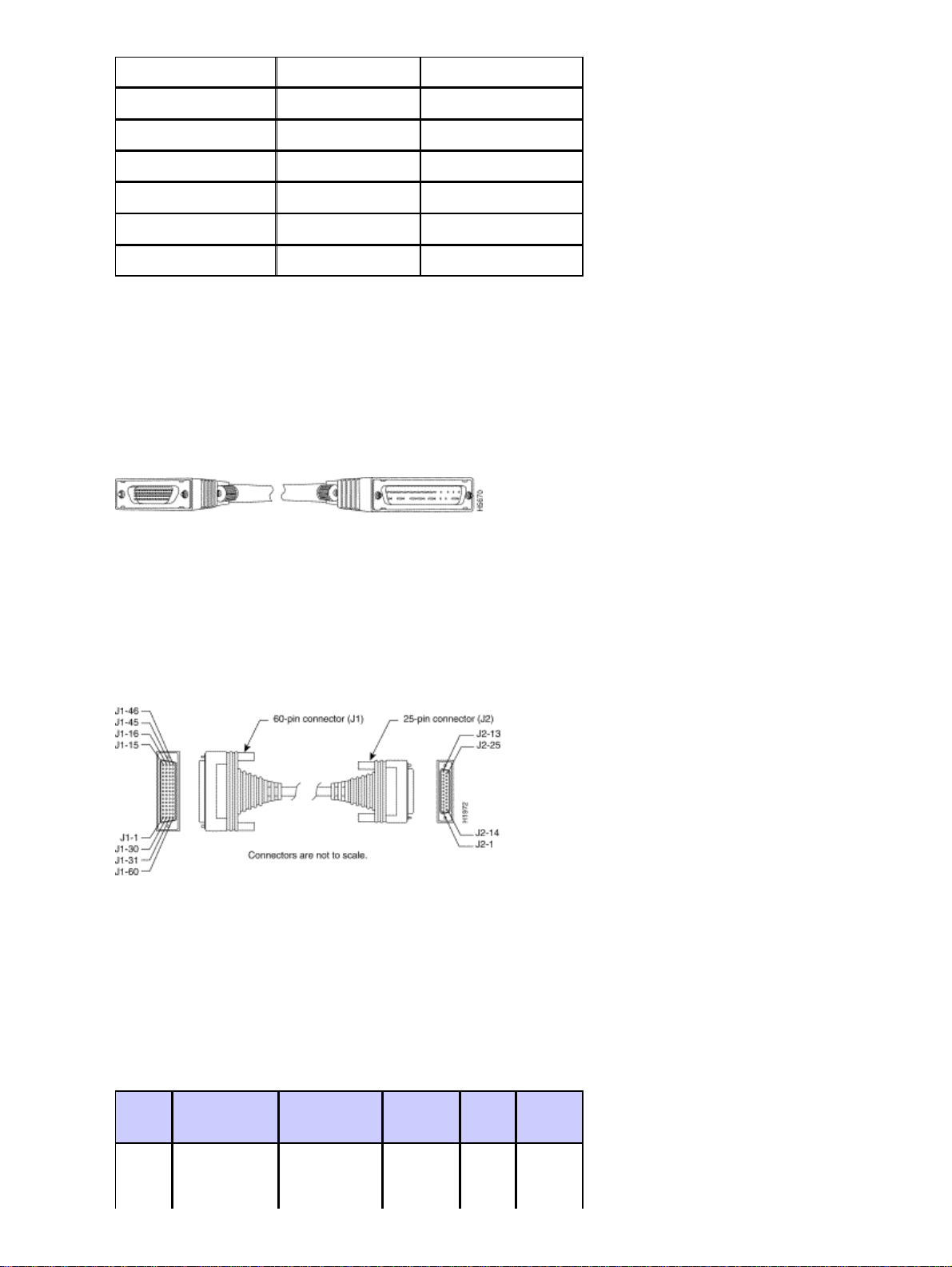
EIA/TIA−232 Serial Cable Assembly
EIA/TIA−232 DTE Cable Pinouts
The table below shows the EIA/TIA−232 DTE cable pinouts (DB−60 to DB−25).
Note: The arrows indicate signal direction:
−−−> indicates DTE to DCE•
<−−− indicates DCE to DTE•
60
1
Pin
J1−50 MODE_0 Shorting
Signal Description Direction 25 Pin Signal
group
− − −
Page 3

J1−51
GND
J1−52
J1−46
J1−41
Shield
J1−36
Shield
J1−42
Shield
J1−35
Shield
J1−34
Shield
J1−45
Shield
J1−33
MODE_DCE
Shield GND Single − J2−1
TxD/RxD
−
RxD/TxD
−
RTS/CTS
−
CTS/RTS
−
DSR/DTR
−
Circuit GND
−
Twisted pair
no. 5
Twisted pair
no. 9
Twisted pair
no. 4
Twisted pair
no. 10
Twisted pair
no. 11
Twisted pair
no. 1
−−−>
−
<−−−
−
−−−>
−
<−−−
−
<−−−
−
−
−
J2−2
Shield
J2−3
Shield
J2−4
Shield
J2−5
Shield
J2−6
Shield
J2−7
Shield
Shield
GND
TxD
−
RxD
−
RTS
−
CTS
−
DSR
−
Circuit
GND
−
Shield
J1−37
Shield
J1−38
Shield
J1−44
Shield
J1−43
Shield
J1−39
Shield
1
Any pin not referenced is not connected.
DCD/LL
−
TxC/NIL
−
RxC/TxCE
−
LL/DCD
−
DTR/DSR
−
TxCE/TxC
−
Twisted pair
no. 12
Twisted pair
no. 8
Twisted pair
no. 7
Twisted pair
no. 2
Twisted pair
no. 3
Twisted pair
no. 6
<−−−
−
<−−−
−
<−−−
−
−−−>
−
−−−>
−
−−−>
−
J2−8
Shield
J2−15
Shield
J2−17
Shield
J2−18
Shield
J2−20
Shield
J2−24
Shield
DCD
−
TxC
−
RxC
−
LTST
−
DTR
−
TxCE
−
Page 4

Serial Cable CAB−232FC
This section presents the cable assembly and pinouts for the CAB−232FC serial cable.
The cable gender for this product (part number 72−0794−01) is Male DB−60 to Female DB−25, mode −
DCE.
This cable is used in the following systems: the Cisco 7000 family, Cisco 4000 series, Cisco 3600 series,
Cisco 2500 series, Cisco 1600 series, Cisco access servers, and AccessPro PC cards. This cable has a male
DB−60 connector on the Cisco end and a female DB−25 connector on the network end.
EIA/TIA−232 DCE Cable Pinouts (DB−60 to DB−25)
The table below shows the EIA/TIA−232 DCE cable pinouts (DB−60 to DB−25).
Note: The arrows indicate signal direction:
−−−> indicates DTE to DCE•
<−−− indicates DCE to DTE•
60 Pin
J1−50
J1−51
J1−46 Shield
J1−36
Shield
J1−41
Shield
J1−35
Shield
J1−42
Shield
J1−43
Signal Description Direction 25 Pin Signal
MODE_0
GND
GND
RxD/TxD
−
TxD/RxD
−
CTS/RTS
−
RTS/CTS
−
Shorting
group
Single − J2−1
Twisted pair
no. 9
Twisted pair
no. 5
Twisted pair
no. 10
Twisted pair
no. 4
− − −
<−−−
−
−−−>
−
<−−−
−
−−−>
−
J2−2
Shield
J2−3
Shield
J2−4
Shield
J2−5
Shield
Shield
GND
TxD
−
RxD
−
RTS
−
CTS
−
Shield
J1−45
Shield
J1−44 LL/DCD −−−> J2−8 DCD
DTR/DSR
−
Circuit
GND
−
Twisted pair
no. 3
Twisted pair
no. 1
−−−>
−
−
−
J2−6
Shield
J2−7
Shield
DSR
−
Circuit
GND
Page 5

Shield − Twisted pair
no. 2
J1−39
− Shield −
Shield
J1−40
Shield
J1−33
Shield
J1−34
Shield
J1−38
Shield
TxCE/TxC
−
NIL/RxC
−
DCD/LL
−
DSR/DTR
−
RxC/TxCE
−
Twisted pair
no. 7
Twisted pair
no. 6
Twisted pair
no. 12
Twisted pair
no. 11
Twisted pair
no. 8
Related Information
Technical Support − Cisco Systems•
−−−>
−
−−−>
−
<−−−
−
<−−−
−
<−−−
−
J2−15
Shield
J2−17
Shield
J2−18
Shield
J2−20
Shield
J2−24
Shield
TxC
−
RxC
−
LTST
−
DTR
−
TxCE
−
All contents are Copyright © 2006−2007 Cisco Systems, Inc. All rights reserved. Important Notices and Privacy Statement.
Updated: Jan 30, 2006 Document ID: 46800
 Loading...