

Page 1

Cisco Catalyst 9600 Series Line Card Installation Note
First Published: 2019-04-15
Last Modified: 2019-12-20
Overview of Cisco Catalyst 9600 Series Line Cards
This document describes the features of a Cisco Catalyst 9600 Series line card. It also provides information
about how to correctly install or replace a line card in the chassis.
Table 1: Supported Line Cards
DescriptionProduct ID
Cisco Catalyst 9600 Series 48-port 25 G1or 10 G or 1 GC9600-LC-48YL
Cisco Catalyst 9600 Series 24-port 40 G/1 G or 12-port 100 GC9600-LC-24C
Cisco Catalyst 9600 Series 48-port 10 G, 5 G, 2.5 G, 1 G, 100 Mbps, or 10 MbpsC9600-LC-48TX
1
G stands for Gigabit Ethernet.
Features of Cisco Catalyst 9600 Series Line Cards
The following sections describe the major features available on the line cards that are supported on Cisco
Catalyst 9600 Series switches. The document also explains the front view of the line cards and the different
LEDs available.
Cisco Catalyst 9600 Series 24-Port 40 G/1 G/12-Port 100 G (C9600-LC-24C)
The following figure shows the front view of a Cisco Catalyst 9600 Series 24-port 40 G/1 G/12-port 100 G
(C9600-LC-24C) with major features identified.
Cisco Catalyst 9600 Series Line Card Installation Note
1
Page 2

Cisco Catalyst 9600 Series 24-Port 40 G/1 G/12-Port 100 G (C9600-LC-24C)
Figure 1: Cisco Catalyst 9600 Series 24-Port 40 G/1 G/12-Port 100 G (C9600-LC-24C)
Table 2: Front Panel Components
3
ports
4
lever
Ejector levers5Status LED1
6Locate (Blue beacon) LED2
Port Link LED for the port in the top
row
7100 G QSFP28 or 40 G/1 G QSFP+
Port Link LED for the port in the
bottom row
--RFID embedded on the left ejector
Cisco Catalyst 9600 Series Line Card Installation Note
2
Page 3

Cisco Catalyst 9600 Series 24-Port 40 G/1 G/12-Port 100 G (C9600-LC-24C)
Table 3: Features Supported on Cisco Catalyst 9600 Series 24-Port 40 G/1G/12-Port 100 G (C9600-LC-24C)
DescriptionFeature
Ports per module
Cisco QSFP to SFP or SFP+ Adapter
(QSA) adapter (CVR-QSFP-SFP10G)
support
• 24 ports of 40 G or 1 G and 12 ports of 100 G: Provides 24x1
G/40 G interfaces by default, which can be converted to 12x100
G ports.
• Supports a mix of 40 G/1 G and 100 G simultaneously.
• All the 24 ports are configured as 40 G/1 G by default. Only the
odd-numbered ports can be configured as 100 G, if required.
• 40 G/1 G: Two ports per port group. A port group constitutes
the top and bottom consecutive ports in a module.
Provides 10 G connectivity on QSFP ports by converting a 40 G/100
G QSFP port into an SFP/SFP+ port.
The line card supports the following configurations using a QSA
adapter in a port group:
• Configuring odd-numbered (top) and even-numbered (bottom)
ports with the QSA adapter.
• Configuring odd-numbered ports with the QSA adapter and
even-numbered ports with 40 G QSFP optics.
Note
If you configure an odd-numbered port with 40 G QSFP
optics and the even-numbered port with the QSA adapter,
the QSA adapter in the even-numbered port will not work.
Chassis slot restrictions
Hardware restrictions
Table 4: Port Mapping for C9600-LC-24C
C9606R: Slots 1, 2, 5, and 6 only. However, you can install a line
card in any of the supported slots.
Configurations with QSFP optics plugged into the top port and the
QSA adapter into the bottom port in a port group are not supported.
2.4 Tbps per slotBandwidth per slot
Port Numbering on the Line CardPort Type
1–2440 G/1 G native ports
25–48100 G native ports
Cisco Catalyst 9600 Series Line Card Installation Note
3
Page 4
Cisco Catalyst 9600 Series 48-Port 25 G/10 G/1 G (C9600-LC-48YL)
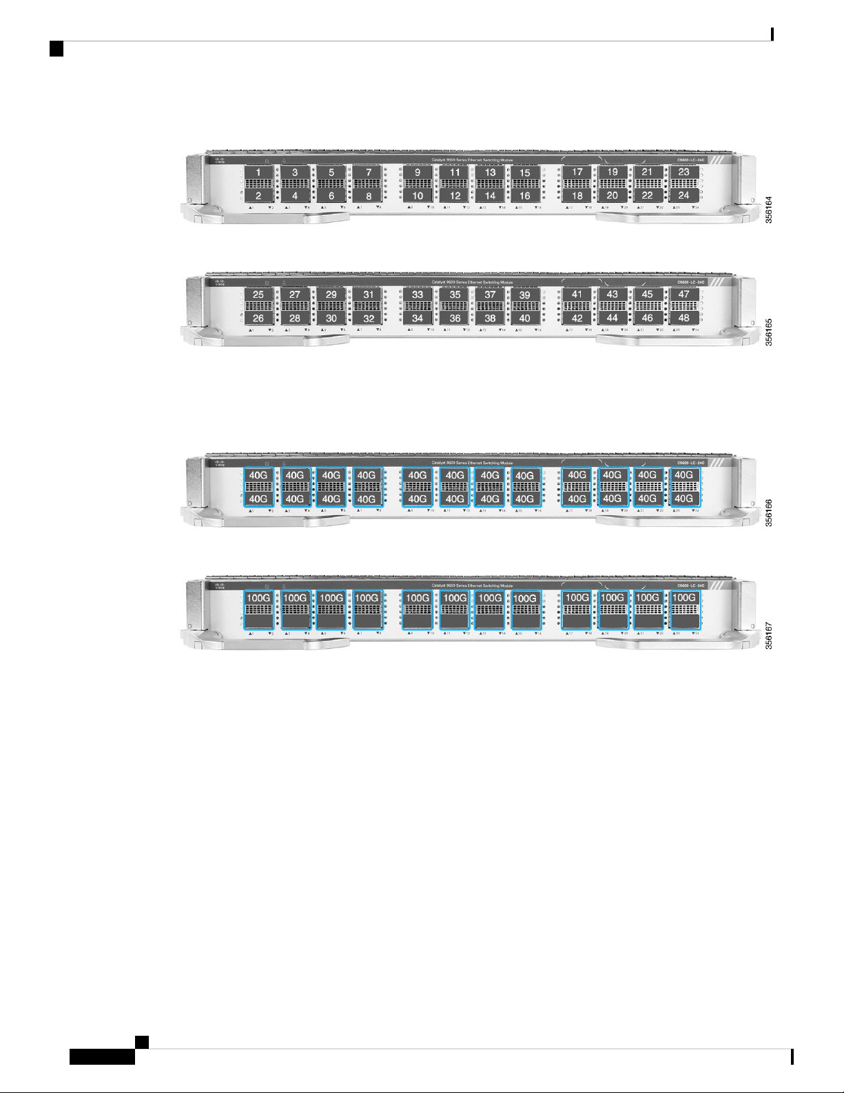
Figure 2: 40 G/1 G Port Numbering on C9600-LC-24C
Figure 3: 100 G Port Numbering on C9600-LC-24C
By default, all the interfaces on a C9600-LC-24C are 40 G/1 G enabled. The default 40 G/1 G interfaces can
be configured to function as 100 G ports using the CLI. However, from each port group, only the odd numbered
ports can be configured with 100 G speed; the even numbered ports in a port group are disabled.
Figure 4: 40 G/1 G (Default) Configuration on C9600-LC-24C
Figure 5: 100 G Configuration on C9600-LC-24C
Cisco Catalyst 9600 Series 48-Port 25 G/10 G/1 G (C9600-LC-48YL)
The following figure shows the front view of a 48-port 25 G/10 G/1 G (C9600-LC-48YL) with the major
features identified.
Cisco Catalyst 9600 Series Line Card Installation Note
4
Page 5

Cisco Catalyst 9600 Series 48-Port 25 G/10 G/1 G (C9600-LC-48YL)
Figure 6: Cisco Catalyst 9600 Series 48-Port 25 G/10 G/1 G (C9600-LC-48YL)
Table 5: Front Panel Components
RFID embedded on the left ejector lever5Status LED1
Ejector levers6Locate (Blue beacon) LED2
Port Link LED for the port in the top row7Sharp-edge hazard icon3
825 G/10 G/1 G SFP28/SFP+ ports4
Port Link LED for the port in the bottom
row
Table 6: Features Supported on Cisco Catalyst 9600 Series 48-Port 25 G/10 G/1 G (C9600-LC-48YL)
DescriptionFeature
Ports per module
• 48 SFP28/SFP+ ports of 25 G, 10 G, and 1 G: Provides 48 25
G, 10 G, or 1 G interfaces by default. These ports can be
interchangeably used as 25 G, 10 G, and 1 G ports.
• All the 48 ports support 25 G, 10 G, or 1 G speeds.
Cisco Catalyst 9600 Series Line Card Installation Note
5
Page 6

Cisco Catalyst 9600 Series 48-Port 10 G/5 G/2.5 G/1 G/100 Mbps/10 Mbps (C9600-LC-48TX)
DescriptionFeature
Chassis slot restrictions
C9606R: Slots 1, 2, 5, and 6 only. However, you can install a line
card in any of the supported slots.
2.4 Tbps per slotBandwidth per slot
Cisco Catalyst 9600 Series 48-Port 10 G/5 G/2.5 G/1 G/100 Mbps/10 Mbps (C9600-LC-48TX)
The following figure shows the front view of a 48-port 10 G/5 G/2.5 G/1 G/100 Mbps/10 Mbps
(C9600-LC-48TX) with the major features identified.
Figure 7: Cisco Catalyst 9600 Series 48-Port 10 G/5 G/2.5 G/1 G/100 Mbps/10 Mbps (C9600-LC-48TX)
Table 7: Front Panel Components
Ejector levers5Status LED1
Port Link LED for the port in the top row6Locate (Blue beacon) LED2
3
710 G/5 G/2.5 G/1 G/100 Mbps/10 Mbps
RJ45 copper ports
Port Link LED for the port in the bottom
row
--RFID embedded on the left ejector lever4
Cisco Catalyst 9600 Series Line Card Installation Note
6
Page 7

Line Card LEDs
Table 8: Features Supported on Cisco Catalyst 9600 Series 48-Port 10 G/5 G/2.5 G/1 G/100 Mbps/10 Mbps (C9600-LC-48TX)
DescriptionFeature
Line Card LEDs
Ports per module
Chassis slot restrictions
Table 9: Line Card LEDs
Blue Beacon
• 48 RJ45 copper ports of 10 G, 5 G, 2.5 G, 1 G, 100 Mbps and
10 Mbps: Provides 48 10 G, 5 G, 2.5 G, 1 G, 100 Mbps and 10
Mbps interfaces by default. These ports can be interchangeably
used as 10 G, 5 G, 2.5 G, 1 G, 100 Mbps and 10 Mbps ports.
• All the 48 ports support 10 G, 5 G, 2.5 G, 1 G, 100 Mbps and
10 Mbps speeds.
C9606R: Slots 1, 2, 5, and 6 only. However, you can install a line
card in any of the supported slots.
2.4 Tbps per slotBandwidth per slot
MeaningLED Position or ColourLED Type
Module is receiving beacon signal.Blue
Port link is up.Green
Port Link
Off
Preparing for Installation and Removal of a Line Card
Safety Warnings
Safety warnings appear throughout this publication in procedures that may harm you if you perform them
incorrectly. A warning symbol precedes each warning statement. The warnings below are general warnings
that are applicable to the entire publication.
Warning
An exposed wire lead from a DC-input power source can conduct harmful levels of electricity. Be sure that
no exposed portion of the DC-input power source wire extends from the connector(s) or terminal block(s).
Statement 122
Port link is disabled, that is, administratively down.Amber
No signal is detected, the link is down, or the port is
not connected.
Cisco Catalyst 9600 Series Line Card Installation Note
7
Page 8

Safety Warnings
Warning
Warning
Warning
Warning
Warning
AC connected units must have a permanent ground connection in addition to the power cable ground wire.
NEBS-compliant grounding satisfies this requirement. Statement 284
High leakage current—earth connection essential before connecting to system power supply. Statement 342
Power Cable and AC Adapter - When installing the product, please use the provided or designated connection
cables/power cables/AC adaptors.Using any other cables/adaptors could cause a malfunction or a fire. Electrical
Appliance and Material Safety Law prohibits the use of UL-certified cables (that have the "UL or CSA" shown
on the code) for any other electrical devices than products designated by CISCO. The use of cables that are
certified by Electrical Appliance and Material Safety Law (that have "PSE" shown on the code) is not limited
to CISCO-designated products. Statement 371
To reduce the risk of electric shock, the chassis of this equipment needs to be connected to permanent earth
ground during normal use. Statement 0445
Read the installation instructions before using, installing or connecting the system to the power source.
Statement 1004
Warning
Warning
Warning
Warning
Class 1 laser product. Statement 1008
There is the danger of explosion if the battery is replaced incorrectly. Replace the battery only with the same
or equivalent type recommended by the manufacturer. Dispose of used batteries according to the manufacturer’s
instructions. Statement 1015
This unit is intended for installation in restricted access areas. A restricted access area can be accessed only
through the use of a special tool, lock and key, or other means of security. Statement 1017
This equipment must be grounded. Never defeat the ground conductor or operate the equipment in the absence
of a suitably installed ground conductor. Contact the appropriate electrical inspection authority or an electrician
if you are uncertain that suitable grounding is available. Statement 1024
Cisco Catalyst 9600 Series Line Card Installation Note
8
Page 9

Safety Warnings
Warning
Warning
Warning
Warning
Warning
Class 1 LED product. Statement 1027
Blank faceplates and cover panels serve three important functions: they prevent exposure to hazardous voltages
and currents inside the chassis; they contain electromagnetic interference (EMI) that might disrupt other
equipment; and they direct the flow of cooling air through the chassis. Do not operate the system unless all
cards, faceplates, front covers, and rear covers are in place. Statement 1029
Only trained and qualified personnel should be allowed to install, replace, or service this equipment. Statement
1030
Hazardous voltage or energy is present on the backplane when the system is operating. Use caution when
servicing. Statement 1034
Ultimate disposal of this product should be handled according to all national laws and regulations. Statement
1040
Warning
Warning
Warning
Warning
Warning
To prevent the system from overheating, do not operate it in an area that exceeds the maximum recommended
ambient temperature of 104°F (40°C). Statement 1047
Stability hazard. The rack stabilizing mechanism must be in place, or the rack must be bolted to the floor
before you slide the unit out for servicing. Failure to stabilize the rack can cause the rack to tip over. Statement
1048
The chassis should be mounted on a rack that is permanently affixed to the building. Statement 1049
Invisible laser radiation may be emitted from disconnected fibers or connectors. Do not stare into beams or
view directly with optical instruments. Statement 1051
Class 1M laser radiation when open. Do not view directly with optical instruments. Statement 1053
Cisco Catalyst 9600 Series Line Card Installation Note
9
Page 10

Preventing ESD Damage
Warning
Warning
Warning
Class I (CDRH) and Class 1M (IEC) laser products. Statement 1055
Invisible laser radiation may be emitted from the end of the unterminated fiber cable or connector. Do not
view directly with optical instruments. Viewing the laser output with certain optical instruments (for example,
eye loupes, magnifiers, and microscopes) within a distance of 100 mm may pose an eye hazard. Statement
1056
IMPORTANT SAFETY INSTRUCTIONS
This warning symbol means danger. You are in a situation that could cause bodily injury. Before you
work on any equipment, be aware of the hazards involved with electrical circuitry and be familiar with
standard practices for preventing accidents. Use the statement number provided at the end of each
warning to locate its translation in the translated safety warnings that accompanied this device. Statement
1071
SAVE THESE INSTRUCTIONS
Warning
The covers are an integral part of the safety design of the product. Do not operate the unit without the covers
installed. Statement 1077
Preventing ESD Damage
ESD damage might occur when modules or other FRUs are improperly handled, resulting in intermittent or
complete failure of the modules or FRUs. Modules consist of printed circuit boards that are fixed in metal
carriers. EMI shielding and connectors are integral components of a carrier. Although the metal carrier helps
to protect the board from ESD, always use an ESD-grounding strap when handling modules. To prevent ESD
damage, follow these guidelines:
• Always use an ESD wrist or ankle strap and ensure that it makes good skin contact.
• Connect the equipment end of the strap to an unfinished chassis surface.
Cisco Catalyst 9600 Series Line Card Installation Note
10
Page 11

Tools Required
Tools Required
• When installing a component, use an available ejector lever to properly seat the bus connectors in the
backplane or midplane. These devices prevent accidental removal, provide proper grounding for the
system, and help to ensure that bus connectors are properly seated.
• When removing a component, use an available ejector lever to release the bus connectors from the
backplane or midplane.
• Handle carriers by available handles or edges only; avoid touching the printed circuit boards or connectors.
• Place a removed component board-side-up on an antistatic surface or in a static-shielding container. If
you plan to return the component to the factory, immediately place it in a static-shielding container.
• Avoid contact between the printed circuit boards and clothing. The wrist strap only protects components
from ESD voltages on the body; ESD voltages on clothing can still cause damage.
• Never attempt to remove the printed circuit board from the metal carrier.
You will need these tools to install or remove supervisor engines and line cards:
• Your own ESD-prevention equipment or the disposable grounding wrist strap included with all upgrade
kits, FRUs, and spares.
• Antistatic mat or antistatic bag
Installing and Removing Line Cards
Installing a Line Card
Warning
Caution
Hazardous voltage or energy is present on the backplane when the system is operating. Use caution when
servicing. Statement 1034
To prevent ESD damage, handle the line cards by the carrier edges only.
Before you begin
• Take the necessary precautions to prevent ESD damage. Wear a grounded ESD wrist strap while handling
the line cards.
• Ensure that you have enough clearance to accommodate any interface equipment that you will connect
directly to the ports.
Procedure
Step 1 Remove the slot blank cover (C9606-SLOT-BLANK=) if it is present, by squeezing the release handles
towards each other (with your thumb and index fingers) and sliding the cover out of the bay. Save it for future
use.
Cisco Catalyst 9600 Series Line Card Installation Note
11
Page 12

Installing a Line Card
Step 2 Remove the new line card from the shipping packaging, being careful to handle the module using only the
module’s metal tray or the front panel. Do not touch the printed circuit board or the connector pins.
Step 3 Pivot the left and the right ejector levers away from the front of the module and hold them while sliding the
line card into the slot.
Step 4 Hold the line card's front panel with one hand and place your other hand under the carrier to support the line
card.
Step 5 Position and carefully slide the line card into the slot. Make sure that you align the sides of the printed circuit
boards with the slot guides on each side of the chassis slot.
Figure 8: Positioning and Sliding the Line Card into the Slot
Step 6 Pivot both the ejector levers inward simultaneously.
Cisco Catalyst 9600 Series Line Card Installation Note
12
Page 13

Figure 9: Pivoting the Ejector Levers Inward
Installing a Line Card
Ejector levers1
Step 7 Install necessary transceivers, if any, into the module ports.
For installation instructions along with safety warnings for the various types of transceivers, see
https://www.cisco.com/en/US/products/hw/modules/ps5455/prod_installation_guides_list.html
Step 8 Attach the necessary network interface cables or other devices to the interface ports.
Step 9 Check the status of the line card:
a) Ensure that the status LED is green.
b) When the switch is online, enter the show module command. Verify that the system acknowledges the
new line card and that the line card status is OK.
c) If the line card is not operational, reseat it. If it is still not operational, contact your Cisco customer service
representative.
Cisco Catalyst 9600 Series Line Card Installation Note
13
Page 14

Removing a Line Card
Removing a Line Card
Warning
Hazardous voltage or energy is present on the backplane when the system is operating. Use caution when
servicing. Statement 1034
Warning
Invisible laser radiation may be emitted from disconnected fibers or connectors. Do not stare into beams or
view directly with optical instruments. Statement 1051
Caution
To prevent ESD damage, handle line cards by the carrier edges only.
Before you begin
• You will need a slot blank cover (C9606-SLOT-BLANK) if the slot is to remain empty.
• Take the necessary precautions to prevent ESD damage. Wear a grounded ESD wrist strap while handling
the modules.
Procedure
Step 1 Disconnect network interface cables, if any, that are attached to the line card ports.
Step 2 If the line card is equipped with removable optical transceivers, immediately install dust plugs into the
transceiver’s optical bores. This prevents possible dust contamination, which can affect port performance.
Step 3 Grasp the left and right ejector levers and slightly push the two ejector levers in and towards the faceplate.
Cisco Catalyst 9600 Series Line Card Installation Note
14
Page 15

Figure 10: Pushing the Ejector Levers Inward
Removing a Line Card
Warning
Make sure that you push the ejector levers slightly inward before you rotate the levers outward.
Failing to do so will deform the injector catch pins on the levers.
Step 4 Press the ejector buttons on the ejector levers of the line card to release the levers from the line card.
Step 5 Grasp the left and right ejector levers and simultaneously rotate the levers outward to disengage the line card
from the backplane connector.
Cisco Catalyst 9600 Series Line Card Installation Note
15
Page 16

Removing a Line Card
Figure 11: Pivoting the Ejector Levers
Ejector levers2Button on the ejector lever1
Step 6 Grasp the front panel of the line card with one hand and place your other hand under the carrier to support
and guide it out of the slot. Do not touch the printed circuit boards or connector pins.
Step 7 Carefully slide the line card straight out of the slot, keeping your other hand under the carrier to guide it.
Cisco Catalyst 9600 Series Line Card Installation Note
16
Page 17

Figure 12: Removing a Line Card from the Slot
Removing a Line Card
Step 8 Place the line card on an antistatic mat or in an antistatic bag.
Step 9 Install a replacement line card after a 15-second wait. Alternatively, if the chassis slot is to remain empty,
install a blank slot cover (C9606-SLOT-BLANK).
Remove slot blanks only when installing a line card. If a line card is removed, ensure that you replace it with
a slot blank immediately. Also, keep the line card in ESD-protective bags when they are not installed in a
chassis.
Caution
Blank faceplates and cover panels serve three important functions: they prevent exposure to hazardous
voltages and currents inside the chassis; they contain electromagnetic interference (EMI) that might
disrupt other equipment; and they direct the flow of cooling air through the chassis. Do not operate
the system unless all cards, faceplates, front covers, and rear covers are in place. Statement 1029
Cisco Catalyst 9600 Series Line Card Installation Note
17
Page 18

THE SPECIFICATIONS AND INFORMATION REGARDING THE PRODUCTS IN THIS MANUAL ARE SUBJECT TO CHANGE WITHOUT NOTICE. ALL STATEMENTS,
INFORMATION, AND RECOMMENDATIONS IN THIS MANUAL ARE BELIEVED TO BE ACCURATE BUT ARE PRESENTED WITHOUT WARRANTY OF ANY KIND,
EXPRESS OR IMPLIED. USERS MUST TAKE FULL RESPONSIBILITY FOR THEIR APPLICATION OF ANY PRODUCTS.
THE SOFTWARE LICENSE AND LIMITED WARRANTY FOR THE ACCOMPANYING PRODUCT ARE SET FORTH IN THE INFORMATION PACKET THAT SHIPPED WITH
THE PRODUCT AND ARE INCORPORATED HEREIN BY THIS REFERENCE. IF YOU ARE UNABLE TO LOCATE THE SOFTWARE LICENSE OR LIMITED WARRANTY,
CONTACT YOUR CISCO REPRESENTATIVE FOR A COPY.
The following information is for FCC compliance of Class A devices: This equipment has been tested and found to comply with the limits for a Class A digital device, pursuant to part 15
of the FCC rules. These limits are designed to provide reasonable protection against harmful interference when the equipment is operated in a commercial environment. This equipment
generates, uses, and can radiate radio-frequency energy and, if not installed and used in accordance with the instruction manual, may cause harmful interference to radio communications.
Operation of this equipment in a residential area is likely to cause harmful interference, in which case users will be required to correct the interference at their own expense.
The following information is for FCC compliance of Class B devices: This equipment has been tested and found to comply with the limits for a Class B digital device, pursuant to part 15 of
the FCC rules. These limits are designed to provide reasonable protection against harmful interference in a residential installation. This equipment generates, uses and can radiate radio
frequency energy and, if not installed and used in accordance with the instructions, may cause harmful interference to radio communications. However, there is no guarantee that interference
will not occur in a particular installation. If the equipment causes interference to radio or television reception, which can be determined by turning the equipment off and on, users are
encouraged to try to correct the interference by using one or more of the following measures:
• Reorient or relocate the receiving antenna.
• Increase the separation between the equipment and receiver.
• Connect the equipment into an outlet on a circuit different from that to which the receiver is connected.
• Consult the dealer or an experienced radio/TV technician for help.
Modifications to this product not authorized by Cisco could void the FCC approval and negate your authority to operate the product.
The Cisco implementation of TCP header compression is an adaptation of a program developed by the University of California, Berkeley (UCB) as part of UCB’s public domain version of
the UNIX operating system. All rights reserved. Copyright©1981, Regents of the University of California.
NOTWITHSTANDING ANY OTHER WARRANTY HEREIN, ALL DOCUMENT FILES AND SOFTWARE OF THESE SUPPLIERS ARE PROVIDED "AS IS" WITH ALL FAULTS.
CISCO AND THE ABOVE-NAMED SUPPLIERS DISCLAIM ALL WARRANTIES, EXPRESSED OR IMPLIED, INCLUDING, WITHOUT LIMITATION, THOSE OF
MERCHANTABILITY, FITNESS FOR A PARTICULAR PURPOSE AND NONINFRINGEMENT OR ARISING FROM A COURSE OF DEALING, USAGE, OR TRADE PRACTICE.
IN NO EVENT SHALL CISCO OR ITS SUPPLIERS BE LIABLE FOR ANY INDIRECT, SPECIAL, CONSEQUENTIAL, OR INCIDENTAL DAMAGES, INCLUDING, WITHOUT
LIMITATION, LOST PROFITS OR LOSS OR DAMAGE TO DATA ARISING OUT OF THE USE OR INABILITY TO USE THIS MANUAL, EVEN IF CISCO OR ITS SUPPLIERS
HAVE BEEN ADVISED OF THE POSSIBILITY OF SUCH DAMAGES.
Any Internet Protocol (IP) addresses and phone numbers used in this document are not intended to be actual addresses and phone numbers. Any examples, command display output, network
topology diagrams, and other figures included in the document are shown for illustrative purposes only. Any use of actual IP addresses or phone numbers in illustrative content is unintentional
and coincidental.
All printed copies and duplicate soft copies of this document are considered uncontrolled. See the current online version for the latest version.
Cisco has more than 200 offices worldwide. Addresses and phone numbers are listed on the Cisco website at www.cisco.com/go/offices.
Cisco and the Cisco logo are trademarks or registered trademarks of Cisco and/or its affiliates in the U.S. and other countries. To view a list of Cisco trademarks, go to this URL: www.cisco.com
go trademarks. Third-party trademarks mentioned are the property of their respective owners. The use of the word partner does not imply a partnership relationship between Cisco and any
other company. (1721R)
©
2019–2020 Cisco Systems, Inc. All rights reserved.
 Loading...