

Page 1
Cisco TelePresence System Codec C90 and Prole 65” Dual using C90 Administrator guide
Contents
Contact us
Introduction
Advanced conguration
Password protection
Web interface
Appendices
Software version TC4.1
FEBRUARY 2011
For Cisco TelePresence System Codec C90 and Prole 65” Dual using C90
D146 35 .05 Prole C90 and Codec C90 Administrator Guide TC4.1, February 2011.
Copyright © 2010-2011 Cisco Systems, Inc. All rights reserved.
Administrator guide
1
www.cisco.com
Page 2

Cisco TelePresence System Codec C90 and Prole 65” Dual using C90 Administrator guide
Contents
Contact us
Introduction
Advanced conguration
Password protection
Web interface
Appendices
Contents
TA - ToC -
Thank you for choosing Cisco!
Hidden text
anchor
Your Cisco product has been designed
to give you many years of safe, reliable
operation.
This part of the product documentation is
aimed at administrators working with the
setup of the Codec C90 and Proles using
Codec C90.
Our main objective with this Administrator
guide is to address your goals and needs.
Please let us know how well we succeeded!
May we recommend that you visit the Cisco
web site regularly for updated versions of this
guide.
The user documentation can be found on
http://www.cisco.com/go/telepresence/docs.
How to use this guide
The top menu bar and the entries in the Table
of Contents are all hyperlinks. Just click on
them to go to the topic.
Table of Contents
Introduction
Introduction ......................................................................... 5
User documentation ........................................................ 5
What’s new in this version .................................................. 6
Software release notes ................................................... 6
Software download ......................................................... 6
User documentation ........................................................ 6
New features and improvements .................................... 6
Cisco TelePresence Touch for C Series ...................... 6
The Advanced conguration menu ................................. 7
New settings ................................................................ 7
Settings that have changed ......................................... 7
Settings that have been removed................................ 7
Prole 65” Dual at a glance ................................................. 8
Codec C90 at a glance ....................................................... 9
Web interface
The web interface ..............................................................11
Connect to the codec.....................................................11
Password protection.......................................................11
Menu options......................................................................12
System information ............................................................13
Making calls from the web interface ..................................14
Making a snapshot ............................................................ 15
User management ............................................................. 16
User roles ...................................................................... 16
The default user account ............................................... 16
Security mode ............................................................... 16
About password and PIN-code ......................................17
Changing your password .................................................. 18
Custom wallpaper ............................................................. 19
File format and picture size ........................................... 19
Upload and activate the wallpaper ................................ 19
Adding a logon banner ...................................................... 20
Uploading certicates ....................................................... 21
Upload the SSL certicate ............................................ 21
Upload the Trusted CA certicates list .......................... 21
Certicates for secure logging .......................................... 22
About audit logging ....................................................... 22
Upload the Audit certicate list ..................................... 22
Enable secure audit logging .......................................... 22
Support log les ................................................................ 23
Historical log les .......................................................... 23
Current log les ............................................................. 23
Viewing XML les .............................................................. 24
Software upgrade ............................................................. 25
Advanced conguration .................................................... 26
Restarting the system ....................................................... 27
Advanced conguration settings
Advanced conguration overview ..................................... 29
The Audio settings ......................................................... 33
The Cameras settings ................................................... 37
The Conference settings ............................................... 39
The GPIO settings ......................................................... 42
The H323 settings ......................................................... 42
The Network settings .................................................... 44
The NetworkPort settings ............................................. 48
The NetworkServices settings ...................................... 49
The Phonebook settings ............................................... 52
The Provisioning settings .............................................. 52
The Security settings .................................................... 53
The SerialPort settings .................................................. 54
The SIP settings ............................................................ 55
The Standby settings..................................................... 56
The SystemUnit settings ............................................... 57
The Time settings .......................................................... 58
The Video settings......................................................... 59
The Experimental settings ............................................. 66
D146 35 .05 Prole C90 and Codec C90 Administrator Guide TC4.1, February 2011.
Copyright © 2010-2011 Cisco Systems, Inc. All rights reserved.
2
www.cisco.com
Page 3

Cisco TelePresence System Codec C90 and Prole 65” Dual using C90 Administrator guide
Contents
Contact us
Introduction
Advanced conguration
Password protection
Web interface
Appendices
Contents
Password protection
Password protection ......................................................... 71
Set the Administrator settings menu password ............ 71
Change your codec password ...................................... 71
Change the user passwords ......................................... 72
Set a root password ...................................................... 72
Appendices
Connecting the Cisco TelePresence Touch controller to
CodecC Series ..................................................................74
About monitors when you have a Codec C90 .................. 75
The main monitor ........................................................... 75
Connecting to HDMI 1 ............................................... 75
Connecting to DVI-I 2, DVI-I 4, HDMI 3 ..................... 75
Moving the OSD using the remote control ................ 75
Moving the OSD using the web interface .................. 75
Moving the OSD using API commands ...................... 75
Dual monitors ................................................................ 75
Dual monitor conguration ......................................... 75
TC console ........................................................................ 76
Video compositor .......................................................... 76
Audio console ................................................................ 76
Optimal denition proles ................................................. 77
ClearPath — Packet loss resilience .................................... 78
Requirement for speaker systems connected to a Cisco
TelePresence C Series codec .......................................... 79
The video input matrix ....................................................... 80
About the matrix ............................................................ 80
Congure the video inputs ............................................ 80
Default congurations .................................................... 80
DNAM for Prole 65” ......................................................... 81
The DNAM Loudspeaker ............................................... 81
The DNAM Amplier ...................................................... 81
Technical specications .................................................... 82
Prole 65” Dual .............................................................. 82
Codec C90 .................................................................... 84
D146 35 .05 Prole C90 and Codec C90 Administrator Guide TC4.1, February 2011.
Copyright © 2010-2011 Cisco Systems, Inc. All rights reserved.
3
www.cisco.com
Page 4

Cisco TelePresence System Codec C90 and Prole 65” Dual using C90 Administrator guide
Contents
Contact us
Introduction
Advanced conguration
Password protection
Web interface
Appendices
Introduction
Chapter 1
Introduction
D146 35 .05 Prole C90 and Codec C90 Administrator Guide TC4.1, February 2011.
Copyright © 2010-2011 Cisco Systems, Inc. All rights reserved.
4
www.cisco.com
Page 5

Cisco TelePresence System Codec C90 and Prole 65” Dual using C90 Administrator guide
Contents
Contact us
Introduction
Advanced conguration
Password protection
Web interface
Appendices
Introduction
Introduction
This document provides you with the information
required to administrate your product at an advanced
level.
Products covered in this guide:
• Prole 65” Dual using C90
• Codec C90
User documentation
The user documentation for the Cisco TelePresence systems,
running the TC software, has several guides suitable for
various user groups.
• Video conference room primer
• Video conference room acoustics guidelines
• Installation guides for the TelePresence systems
• Software release notes for the TC software
• Getting started guide for the TelePresence systems
• User guide for the TelePresence systems
• When using the Touch controller, ref. TC4.1
version of the user guide
• When using the Remote Control, ref. TC4.0
version of the user guide
• Quick reference guides for the TelePresence systems
• Administrator guides for the TelePresence systems
• Camera user guide for the PrecisionHD cameras
• API reference guides for the Codec C Series
• TC Console user guide for the Codec C Series
• Physical interfaces guides for the Codec C Series
• Regulatory compliance and safety information guides
• Legal & license information for products using TC software
Download the user documentation
Go to:
in the right pane, select:
http://www.cisco.com/go/telepresence/docs,
• TelePresence Multipurpose Endpoints for the Prole Series.
• TelePresence Peripherals for the PrecisionHD cameras,
microphones, Touch unit, and remote controls.
• TelePresence Solutions Platform for the Codec C Series
and Quick Set C20.
D146 35 .05 Prole C90 and Codec C90 Administrator Guide TC4.1, February 2011.
Copyright © 2010-2011 Cisco Systems, Inc. All rights reserved.
5
www.cisco.com
Page 6
Cisco TelePresence System Codec C90 and Prole 65” Dual using C90 Administrator guide
Contents
Contact us
Introduction
Advanced conguration
Password protection
Web interface
Appendices
Introduction
What’s new in this version
This section provides an overview of the new and changed API
commands and new features in the TC4.1.0 software version.
Software release notes
For a complete overview of the news and changes, we
recommend reading the Software Release Notes (TC4).
Go to:
tsd_products_support_series_home.html
Software download
For software download go to: http://www.cisco.com/cisco/
software/navigator.html
User documentation
Go to: http://www.cisco.com/go/telepresence/docs,
in the right pane, select:
• TelePresence Multipurpose Endpoints for the Prole Series.
• TelePresence Peripherals for the PrecisionHD cameras,
• TelePresence Solutions Platform for the Codec C Series
http://www.cisco.com/en/US/products/ps11422/
microphones, Touch unit, and remote controls.
and Quick Set C20.
New features and improvements
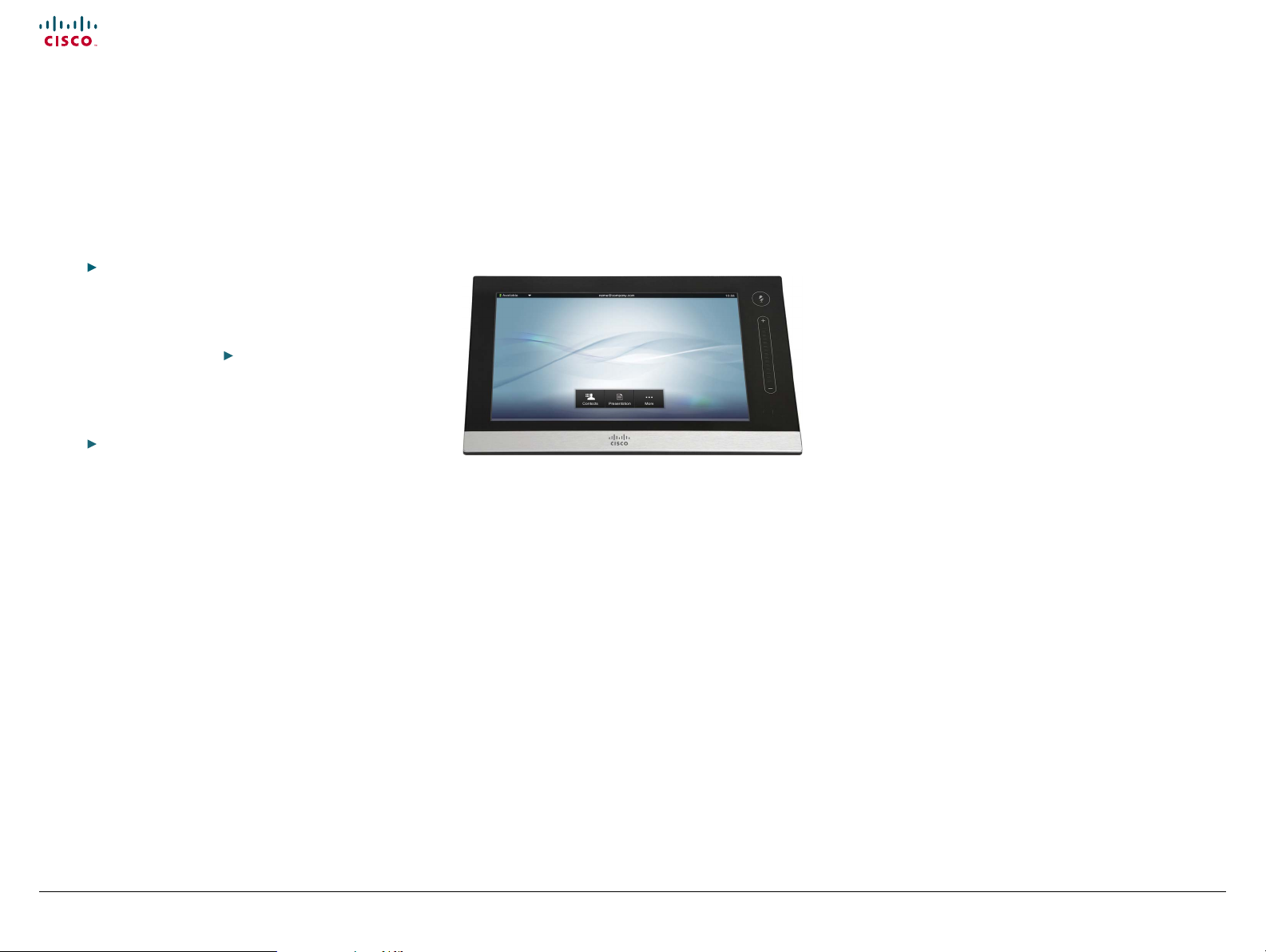
Cisco TelePresence Touch for C Series
The Cisco TelePresence Touch is a touch based user interface
that supports Cisco’s vision for a natural user experience.
You can make video calls, share content, and access some
advanced features - all with a simple tap of the nger.
The Cisco TelePresence Touch is now available for:
• Cisco TelePresence System Codec C Series (C40, C60, C90)
• Cisco TelePresence System Prole Series using Codec C Series
• Cisco TelePresence System Quick Set C20
NOTE: Cisco TelePresence Touch for C Series requires
software version TC4.1.0 or later.
Supported features:
• Calling
• Call control
• Conferencing
• Presenting
• Presentation source selection
• Layout handling
• Directory handling
• Favorites list
• Call history management
• Basic system conguration
• Basic presence control
• Camera control
• Limited to one camera
• Excluding camera presets
• Far end camera control on MultiSite (MultiSite is not
supported on Quick Set C20)
• Volume control
• Microphone mute control
• EMC resilience mode
• All in one “search and dial” mechanism
• Provisioning of system settings and phonebook is
supported. Provisioning of software upgrade is not
supported in this release
• Password protection of the Administrator Settings
The Administrator Settings menu on the Touch controller
can be password protected. This is done from a command
line interface with an API (Application Programmer Inter face)
command. The password protection options are described in
the C Series administrator guides.
D146 35 .05 Prole C90 and Codec C90 Administrator Guide TC4.1, February 2011.
Copyright © 2010-2011 Cisco Systems, Inc. All rights reserved.
NOTE: When using the touch controller most of the system
conguration is done from the web interface. The web
interface is described in the C Series administrator guides.
The Cisco TelePresence Touch for C Series can be connected
to the codec over LAN or directly through network port 2.
Direct connection applies to Codec C40, C60 and C90.
6
www.cisco.com
Page 7

Cisco TelePresence System Codec C90 and Prole 65” Dual using C90 Administrator guide
Contents
Contact us
Introduction
Advanced conguration
Password protection
Web interface
Appendices
Introduction
The Advanced conguration menu
New settings
NetworkPort [2] Mode
Video Input Source [1..5] Type
Settings that have changed
Provisioning Mode
• Added argument “VCS”
Video SelfviewPosition
• Added argument “CenterRight”
Settings that have been removed
SystemUnit Type
Experimental settings
The Experimental settings are beta settings. These settings
can be used ‘as is’, and are not fully documented.
NOTE: The Experimental settings are likely to change.
New settings:
Experimental NetworkServices UPnP Mode
Experimental NetworkServices UPnP Timeout
Experimental SystemUnit MenuType
D146 35 .05 Prole C90 and Codec C90 Administrator Guide TC4.1, February 2011.
Copyright © 2010-2011 Cisco Systems, Inc. All rights reserved.
7
www.cisco.com
Page 8
Cisco TelePresence System Codec C90 and Prole 65” Dual using C90 Administrator guide
Contents
Contact us
Introduction
Advanced conguration
Password protection
Web interface
Appendices
Introduction
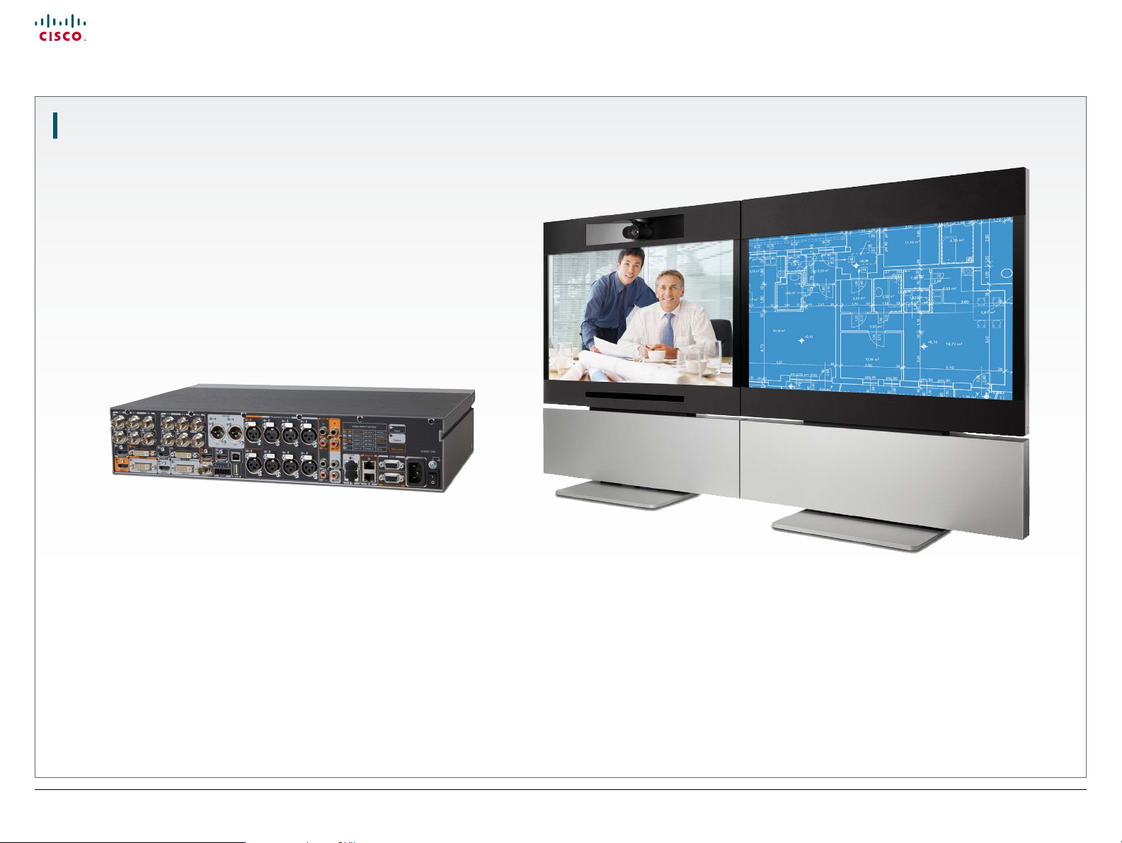
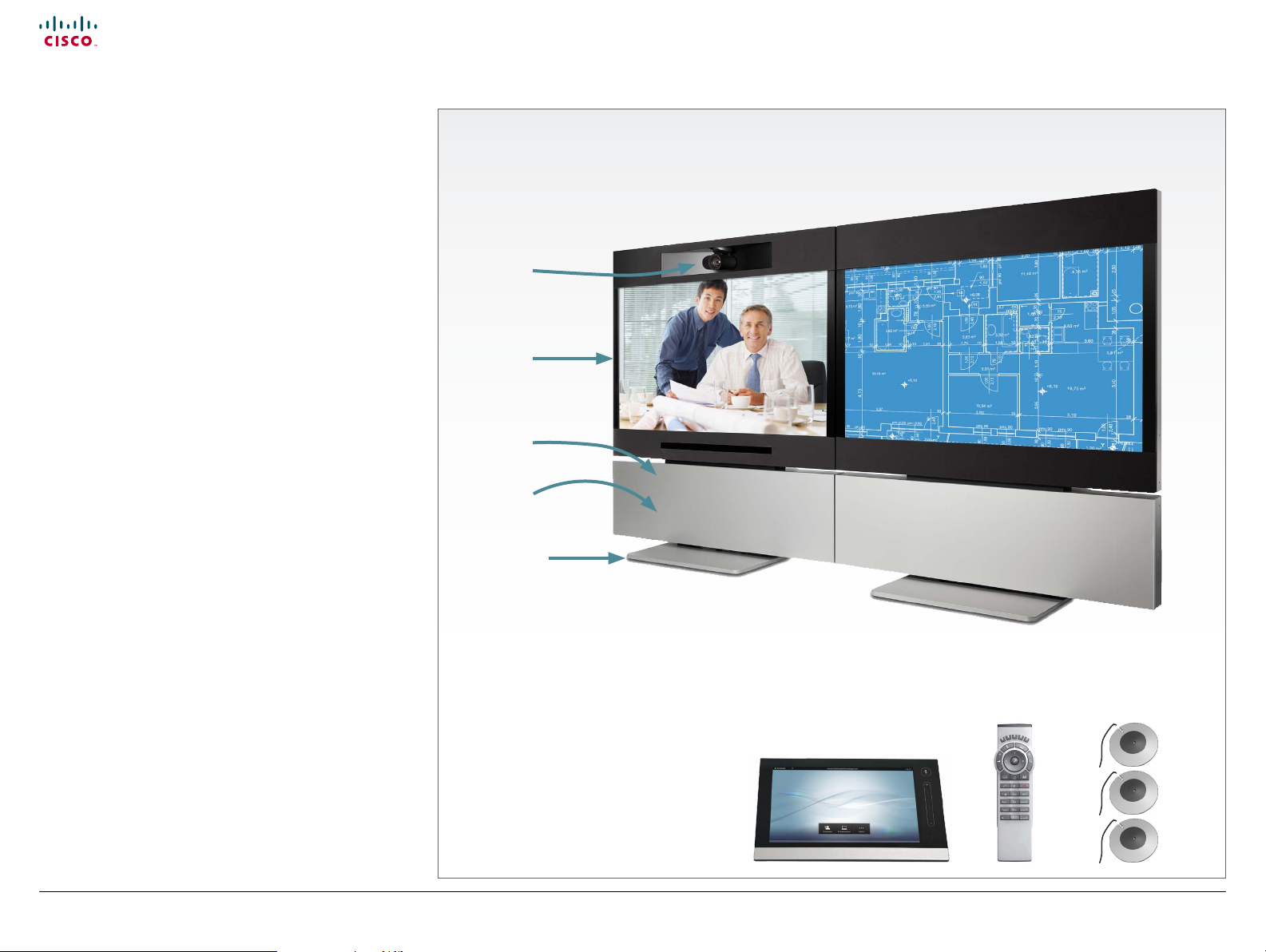
Prole 65” Dual at a glance
Codec C90
• Full HD video.
• High resolution data sharing.
• Full HD Multisite.
• Rich I/O capabilities.
PrecisionHD 1080p
Full HD Camera designed for visual communication with:
• 12 × optical zoom.
• Fast and precise pan, tilt and zoom.
Dual monitor 65”
Full HD LCD Display.
Audio module
Wide band audio module supporting:
• 20 kHz AAC-LD.
• Full echo canceling.
• Stereo.
Audio amplier
Optimized DNAM for the Prole system, providing crystal clear
and natural audio.
The Prole 65” Dual is delivered with:
Presentation unit
Main system
PrecisionHD
1080p camera
2 × Monitor 65’’
Audio amplier
(DNAM)
Codec C90
Foot stand
Microphones
3 × Microphones with cables.
Operating devices
Touch controller for C Series.
Remote control with 4 × AAA batteries.
Foot stand
Floor standing foot plate.
D146 35 .05 Prole C90 and Codec C90 Administrator Guide TC4.1, February 2011.
Copyright © 2010-2011 Cisco Systems, Inc. All rights reserved.
Remote control
Touch controller
8
3 × Microphones
www.cisco.com
Page 9
Cisco TelePresence System Codec C90 and Prole 65” Dual using C90 Administrator guide
Contents
Contact us
Introduction
Advanced conguration
Password protection
Web interface
Appendices
Introduction
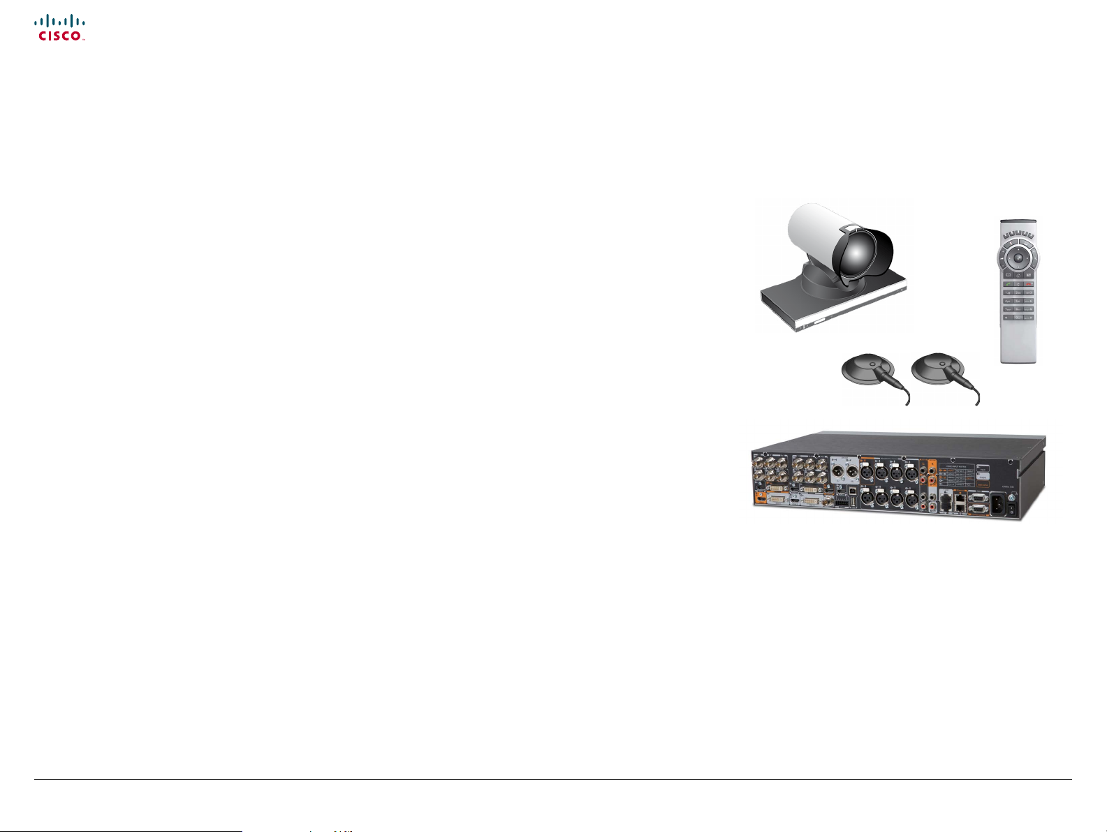
Codec C90 at a glance
The Codec C90 is used in telepresence and collaboration
projects, having the ultimate collaboration engine with HD
video and audio, tremendous power and the highest level of
exibility for any project.
Design features
• The best, most powerful codec available with the ultimate
video and audio quality.
• 2U high, rack mountable, with special rack mounting
solution included.
• Professional grade connectors.
• Unmatched quality and exibility.
• Standards-compliant 1080p solution-compatible with
standards-based video without losing features.
Application features
• 1080p30 HD Individual Transcoding embedded Multisite.
• Collaborate on virtually anything with 5 simultaneous video
inputs.
• HD Collaboration with 1080p30 or UXGA (UXGA ready and
available with future software).
• Limitless integration possibilities.
• Ideal for telepresence and collaboration studios,
boardrooms, auditoriums, education and tele-medicine
applications.
Performance features
• Optimal Denition up to 1080p.
• H.323/SIP up to 6 Mbps point-to-point up to 10 Mbps total
MultiSite bandwidth.
• Connect up to 12 HD sources and 8 microphones directly
into the interface.
• Full Duplex Audio with High Quality Stereo Sound.
• Full APIs, see the API Guide for Codec C90.
Integrator package
The integrator package of the Codec C90 comes with the
PrecisionHD 1080p camera, two microphones, cables and
remote control.
D146 35 .05 Prole C90 and Codec C90 Administrator Guide TC4.1, February 2011.
Copyright © 2010-2011 Cisco Systems, Inc. All rights reserved.
9
www.cisco.com
Page 10

Cisco TelePresence System Codec C90 and Prole 65” Dual using C90 Administrator guide
Contents
Contact us
Introduction
Advanced conguration
Password protection
Web interface
Appendices
Web interface
Chapter 2
Web interface
D146 35 .05 Prole C90 and Codec C90 Administrator Guide TC4.1, February 2011.
Copyright © 2010-2011 Cisco Systems, Inc. All rights reserved.
10
www.cisco.com
Page 11
Cisco TelePresence System Codec C90 and Prole 65” Dual using C90 Administrator guide
Contents
Contact us
Introduction
Advanced conguration
Password protection
Web interface
Appendices
Web interface
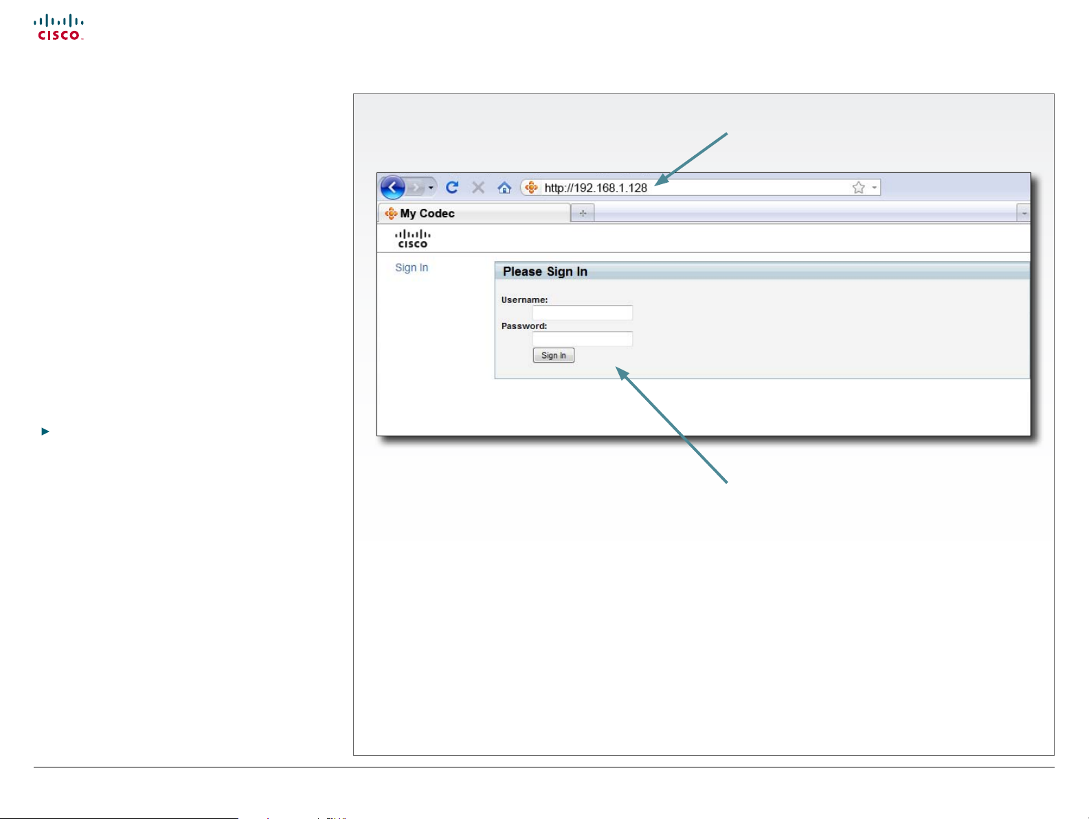
The web interface
The web interface allows for remote administration of the
system.
Connect to the codec
Open a web browser and enter the IP address of the
codec.
How to nd the IP address:
To nd the IP address, open the System Information page
using the remote control. Navigate to Home > Settings >
System Information.
Password protection
In order to access the web interface you must sign in. The
username and password are the same as dened for the
codec. The default username is admin with no password
set.
Read more about password protecting your codec in the
Password protection chapter.
Signing in
1. Enter the IP address
of the codec.
2. Enter the username
and password and
press Sign In.
D146 35 .05 Prole C90 and Codec C90 Administrator Guide TC4.1, February 2011.
Copyright © 2010-2011 Cisco Systems, Inc. All rights reserved.
11
www.cisco.com
Page 12
Cisco TelePresence System Codec C90 and Prole 65” Dual using C90 Administrator guide
Contents
Contact us
Introduction
Advanced conguration
Password protection
Web interface
Appendices
Web interface
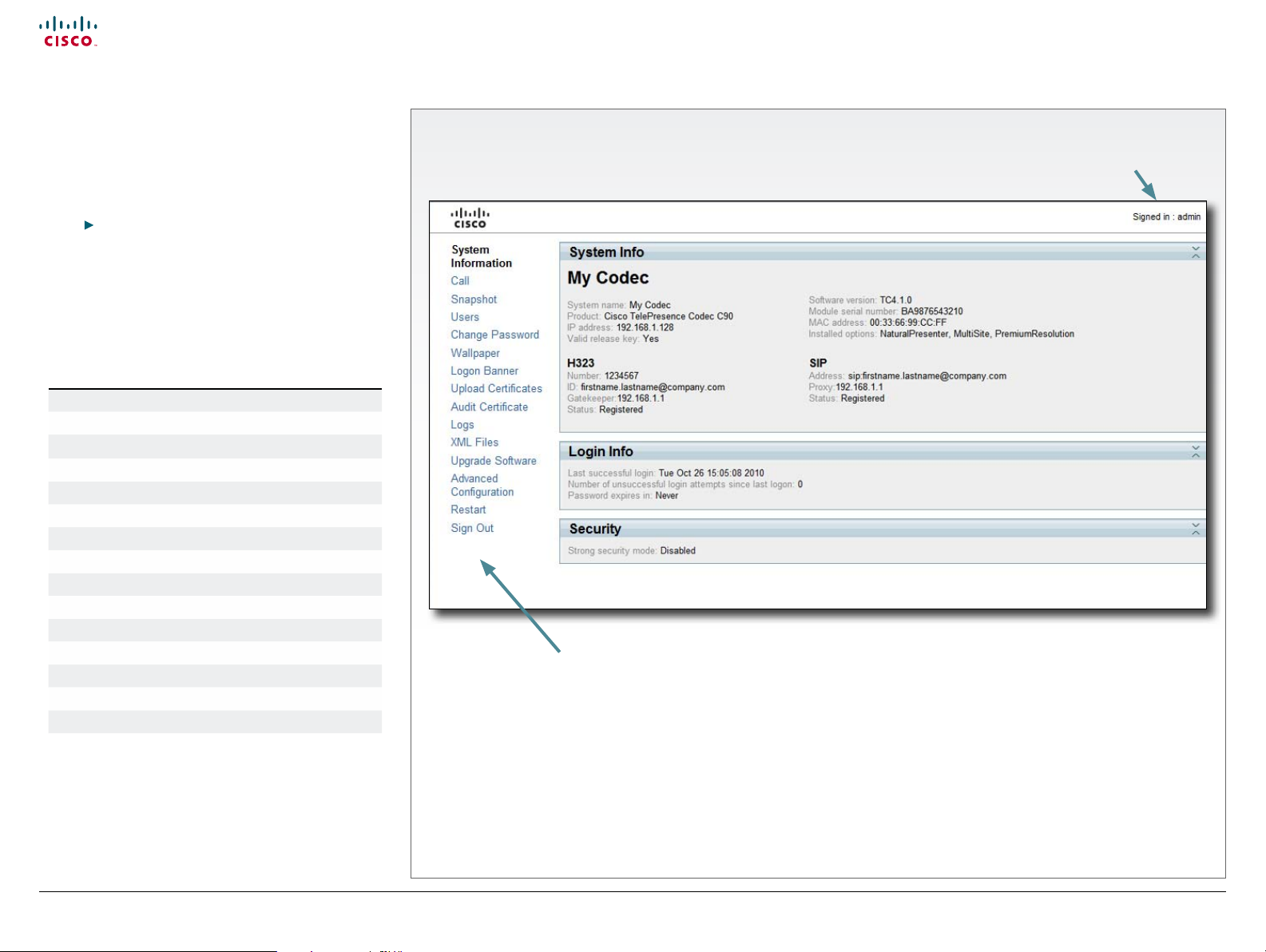
Menu options
You will nd the interactive menus on the left hand side
of the web interface. When you click a menu option, a
corresponding web page will open.
The role of the logged in user determines which menu
options are available. You can read more about user roles
in the
User management section.
The user name of the signed in user is always displayed in
the upper right corner.
The table below shows which menu options are available
for users having ADMIN, AUDIT or USER roles. Note that
the default admin user holds all three roles.
ADMIN AUDIT USER
System Information
Call
Snapshot
Users
Change Password
Wallpaper
Logon Banner
Upload Certicates
Audit Certicate
Logs
XML Files
Upgrade Software
Advanced Conguration
Restart
Sign Out
The interactive menus
Current signed in user
Interactive menus
Click on the menu options to access
the pages. Which menu options are
available depends on the role of the
logged in user.
D146 35 .05 Prole C90 and Codec C90 Administrator Guide TC4.1, February 2011.
Copyright © 2010-2011 Cisco Systems, Inc. All rights reserved.
12
www.cisco.com
Page 13
Cisco TelePresence System Codec C90 and Prole 65” Dual using C90 Administrator guide
Contents
Contact us
Introduction
Advanced conguration
Password protection
Web interface
Appendices
Web interface
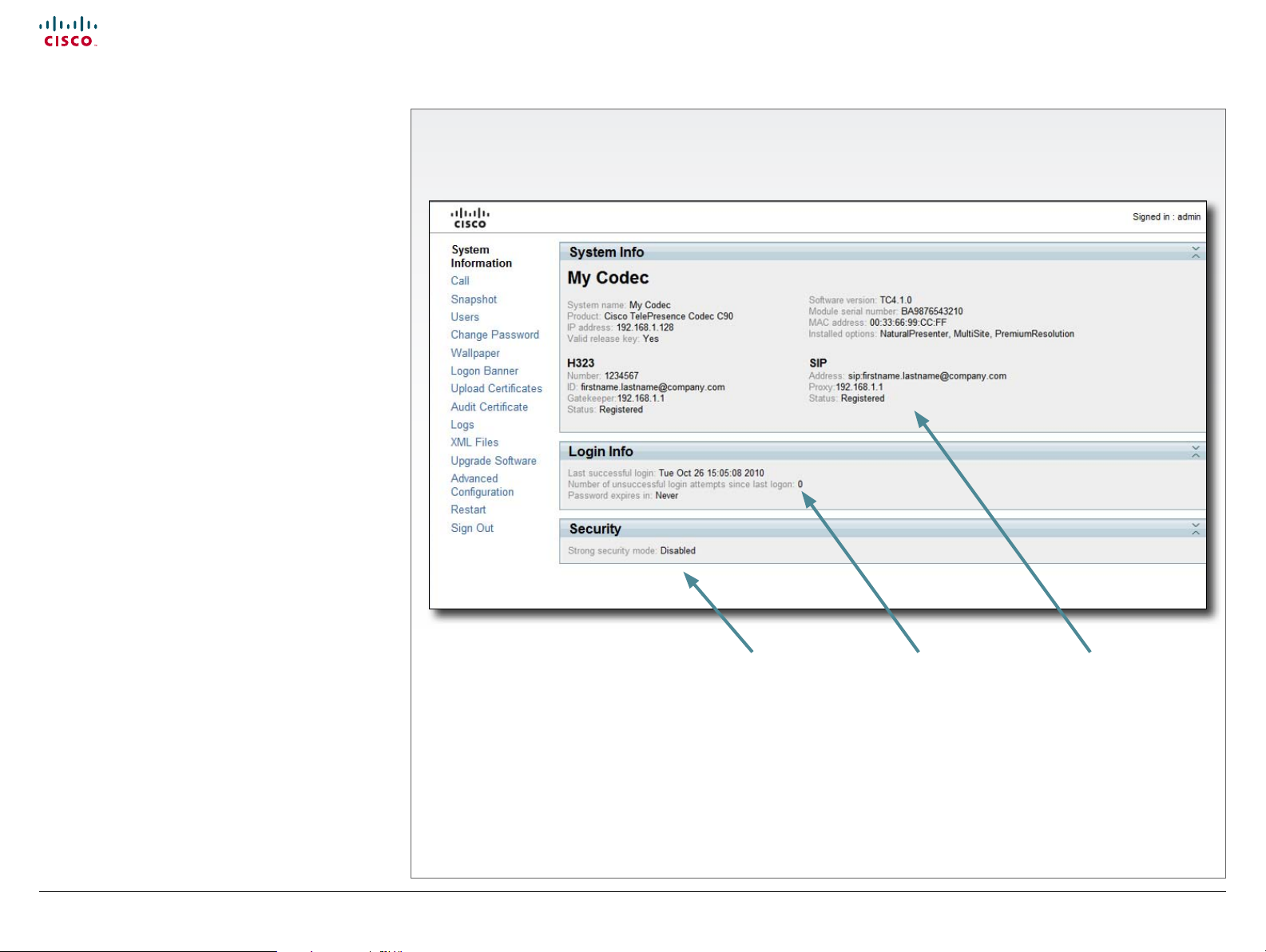
System information
You can nd an overview of your video system set-up on
the System Information page.
The System Information page
D146 35 .05 Prole C90 and Codec C90 Administrator Guide TC4.1, February 2011.
Copyright © 2010-2011 Cisco Systems, Inc. All rights reserved.
Security information
Information about the
current security mode
(strong security mode
available for JTIC labeled
devices).
13
Login information
Information about recent
login attempts and
password expiry.
System information
Information about system
name, product type,
software version, IP
address, etc.
www.cisco.com
Page 14
Cisco TelePresence System Codec C90 and Prole 65” Dual using C90 Administrator guide
Contents
Contact us
Introduction
Advanced conguration
Password protection
Web interface
Appendices
Web interface
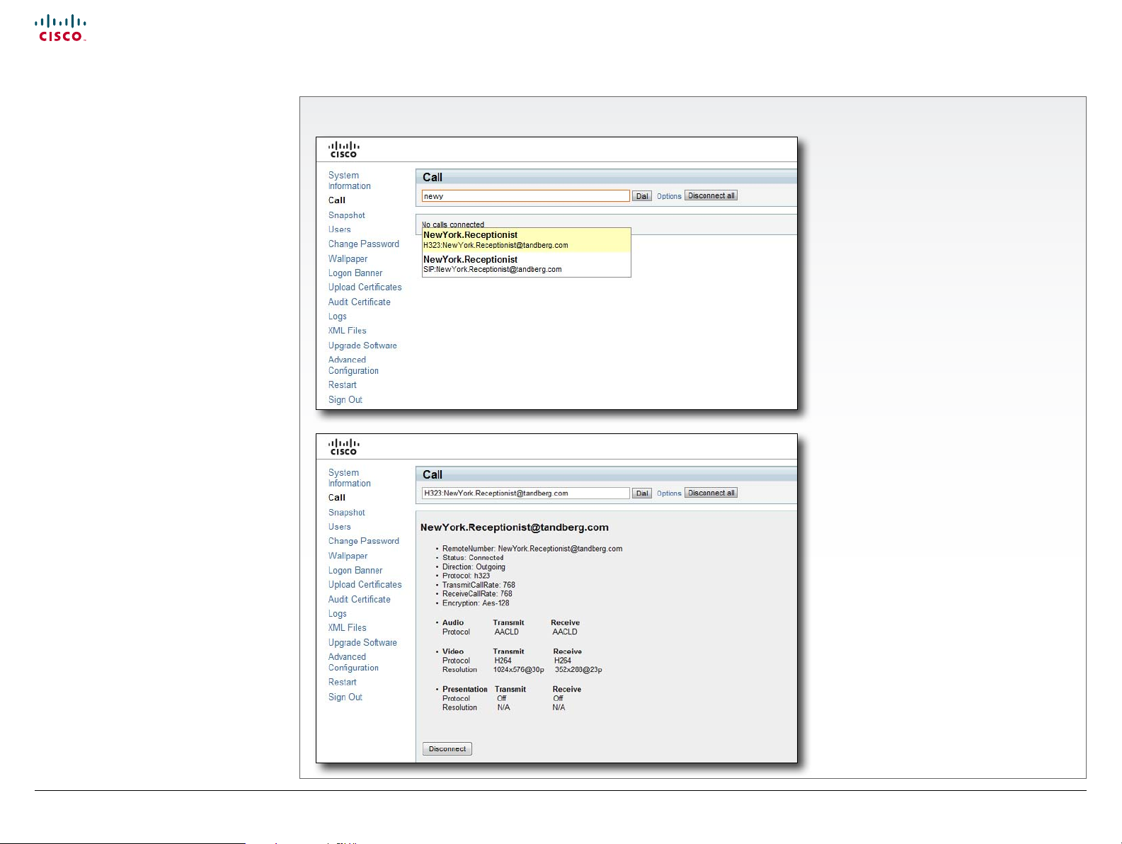
Making calls from the web interface
Sometimes, e.g. when you are conguring
the system from a remote location, it is
convenient to be able to make calls from the
video system to ensure everything works as
expected.
The Call page
Make a call
Input eld: Enter one or more characters
in the input eld, until the name you want
to call appears in the dynamic search list
or, enter the complete name or number.
Dial: Press Dial to initiate the call.
Disconnect all: Press Disconnect all to
end all calls.
Options: Click Options to change the bit
rate for this call. Select the Call rate in the
drop down list.
The call status page
The call status page appear when
you make a call. Please allow for
approximately 30 seconds after the call is
up before checking call details.
You will nd the following information on
the call status page:
• Remote number
• Status: Connected
• Direction: Incoming/Outgoing
• Protocol: H323/SIP
• Transmit and receive call rates
• Encryption
• Audio: Transmit and receive protocols
• Video: Transmit and receive protocols
and resolutions
• Presentation: Transmit and receive
protocols and resolutions
D146 35 .05 Prole C90 and Codec C90 Administrator Guide TC4.1, February 2011.
Copyright © 2010-2011 Cisco Systems, Inc. All rights reserved.
14
www.cisco.com
Page 15
Cisco TelePresence System Codec C90 and Prole 65” Dual using C90 Administrator guide
Contents
Contact us
Introduction
Advanced conguration
Password protection
Web interface
Appendices
Web interface
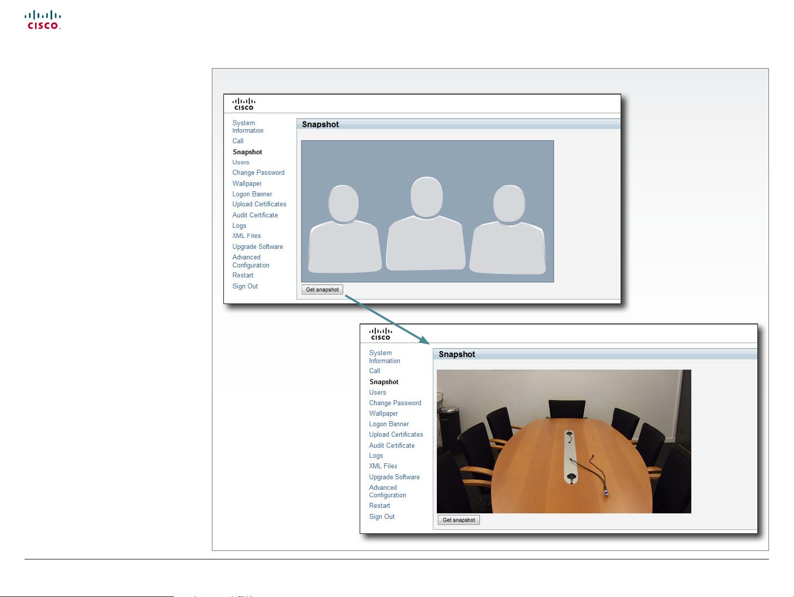
Making a snapshot
When administering the video system from
a remote location, you can use the web
interface snapshot feature to check the view
of the main video input source.
This feature is disabled by default. The feature
can be enabled only when you have direct
access to the codec, i.e. from the on screen
menu or by using the command line interface
via the codec serial data port.
Using the on screen menu
From the Advanced conguration menu,
navigate to Video > AllowWebSnapshots and
select On to enable the snapshot feature.
Using the command line interface
Enter the following command to enable the
snapshot feature:
Video AllowWebSnapshots <Off/On>.
The Snapshot page
Make a snapshot
1. Press Get snapshot. The
snapshot will be displayed on
the web interface.
D146 35 .05 Prole C90 and Codec C90 Administrator Guide TC4.1, February 2011.
Copyright © 2010-2011 Cisco Systems, Inc. All rights reserved.
15
www.cisco.com
Page 16
Cisco TelePresence System Codec C90 and Prole 65” Dual using C90 Administrator guide
Contents
Contact us
Introduction
Advanced conguration
Password protection
Web interface
Appendices
Web interface
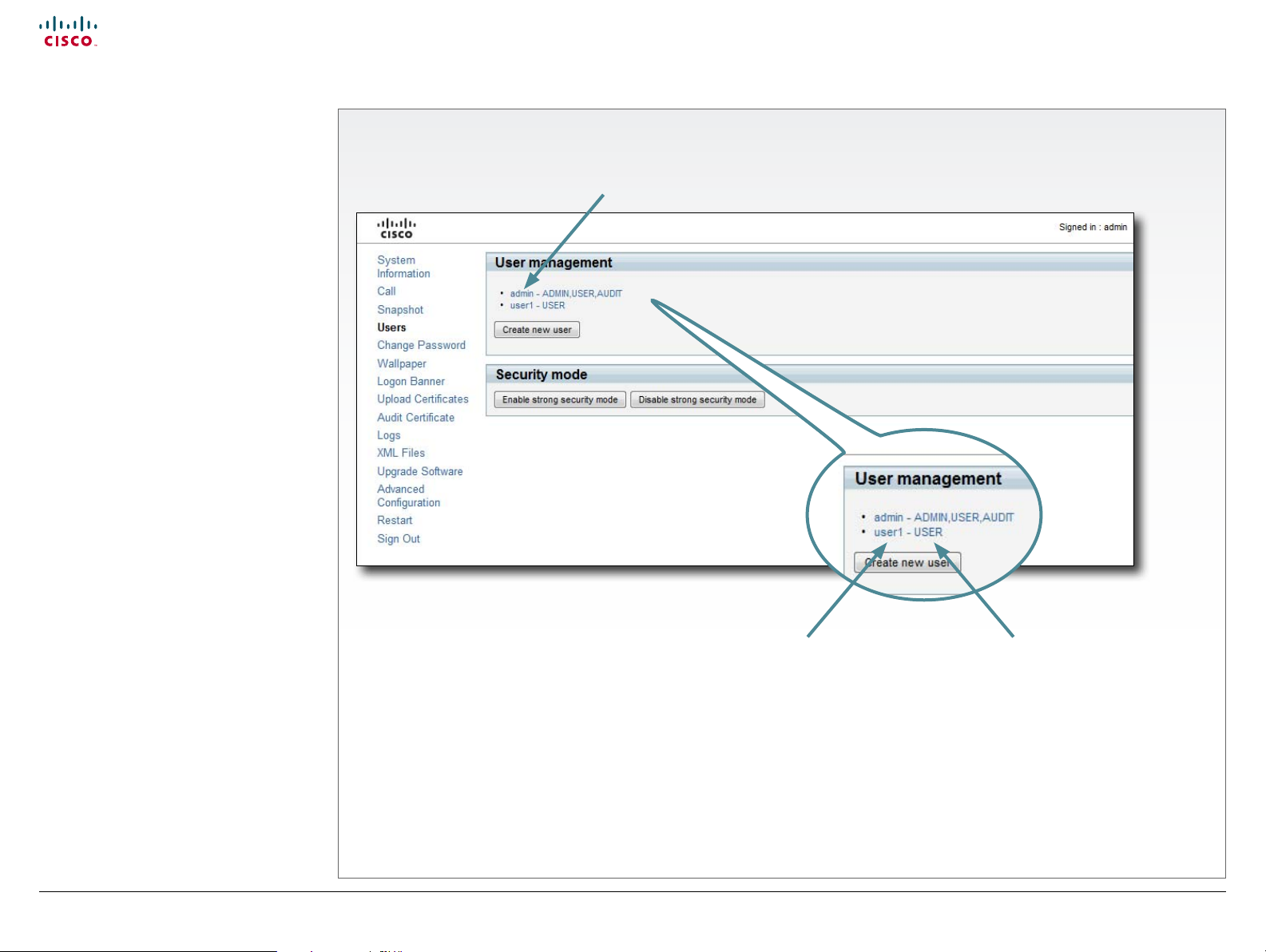
User management
From this page you can manage the user
accounts of your video system. You can
create a new user, edit the details of an
existing user, and delete a user.
User roles
You must assign one or more user roles
to a user account. Three user roles, which
possess dierent system rights, are dened:
• ADMIN: A user with ADMIN rights can
create a new user and change all settings,
except the security audit congurations.
This user cannot upload audit certicates.
• USER: A user with USER rights can make
calls and search the phonebook.
• AUDIT: A user with AUDIT rights can
change the security audit congurations
and upload audit certicates.
The roles ADMIN, USER and AUDIT have nonoverlapping rights, but a user can be created
with one or more roles to combine the rights
of more than one role.
NOTE: It is very important that at least one
user has ADMIN rights at all times.
The default user account
The system comes with a default user
account. The user name is admin with no
password set. The admin user has USER,
ADMIN and AUDIT roles.
It is highly recommended to set a password
for this user.
Security mode
If you have a JTIC labeled system, you can
enable/disable the strong security mode from
this page. Strong security mode sets very
strict password requirements, and requires all
users to change their password on next login.
The Users page
The system comes with admin as default
user account. The admin user possesses
USER, ADMIN and AUDIT roles.
User name
You can create as many
user accounts as you
like on your system.
User role(s)
Each user must have
one or more roles.
D146 35 .05 Prole C90 and Codec C90 Administrator Guide TC4.1, February 2011.
Copyright © 2010-2011 Cisco Systems, Inc. All rights reserved.
16
www.cisco.com
Page 17
Cisco TelePresence System Codec C90 and Prole 65” Dual using C90 Administrator guide
Contents
Contact us
Introduction
Advanced conguration
Password protection
Web interface
Appendices
Web interface
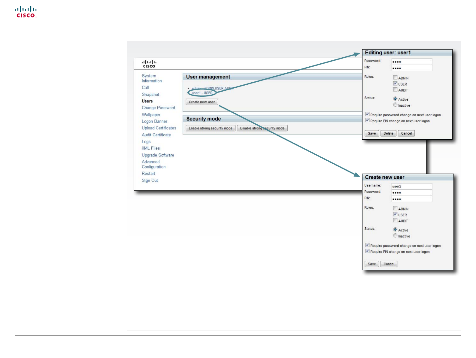
User management,
continued...
If you have ADMIN rights you can manage
users as described on this page.
About password and PIN-code
The password is used to access the web
interface and the command line interfaces
(SSH, Telnet and serial port), while the PIN is
used to access the on screen menus.
The Users page
Create a new user account
1. Press Create new user.
2. Fill in the Username, Password and PIN
code, and select the user role(s) for this
user account. As a default the user have
to change the password and PIN code
when signing in for the rst time.
3. Set the Status to Active to activate the
us er.
4. Press Save to save the changes.
Edit user details
1. Select the name of an existing user to
open the Editing user window.
2. Edit the details.
3. Press Save to save the changes or
Cancel to go back one step without
storing the information.
Deactivate a user account
1. Select the name of an existing user to
open the Editing user window.
2. Set the Status to Inactive.
3. Press Save to save the changes.
Delete a user account
1. Select the name of the user to open the
Editing user window.
2. Press Delete.
CAUTION: Do never delete all users with
ADMIN rights.
D146 35 .05 Prole C90 and Codec C90 Administrator Guide TC4.1, February 2011.
Copyright © 2010-2011 Cisco Systems, Inc. All rights reserved.
17
www.cisco.com
Page 18
Cisco TelePresence System Codec C90 and Prole 65” Dual using C90 Administrator guide
Contents
Contact us
Introduction
Advanced conguration
Password protection
Web interface
Appendices
Web interface
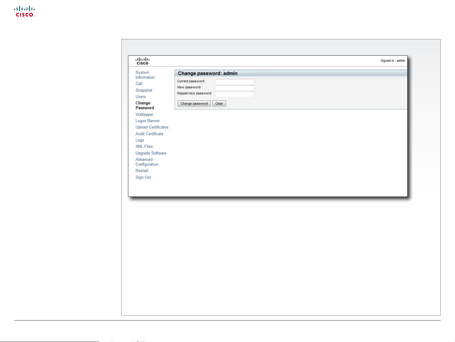
Changing your password
When you are signed in, you can change your
own password. In the example to the right, the
admin user is signed in.
NOTE: It is highly recommended to set a
password for all users with ADMIN rights.
The password is a string with 0–255
characters.
The Change Password page
Change your password
1. Enter your current password, your
2. Press Change password to change the
D146 35 .05 Prole C90 and Codec C90 Administrator Guide TC4.1, February 2011.
Copyright © 2010-2011 Cisco Systems, Inc. All rights reserved.
new password, and repeat the new
password in the input elds.
If no password is set, leave the current
password input eld empty.
If you want to remove a password, leave
the new password input elds empty.
password.
18
www.cisco.com
Page 19
Cisco TelePresence System Codec C90 and Prole 65” Dual using C90 Administrator guide
Contents
Contact us
Introduction
Advanced conguration
Password protection
Web interface
Appendices
Web interface
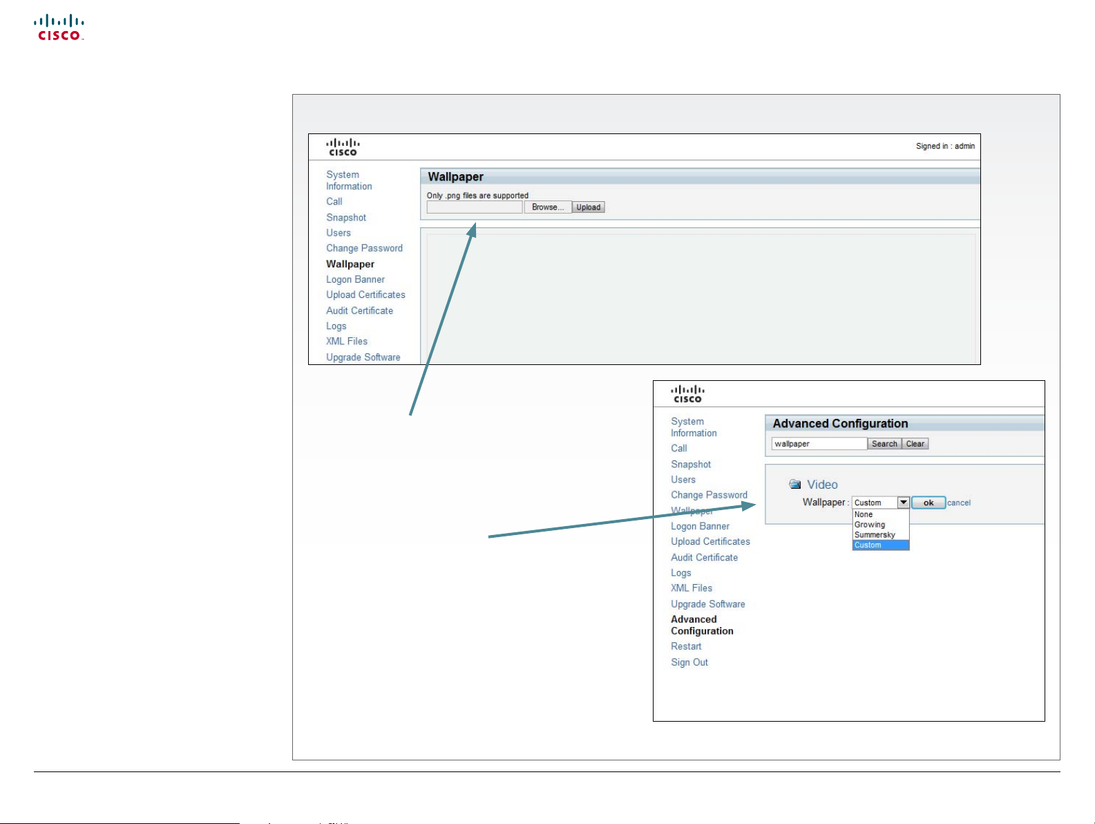
Custom wallpaper
If you want the company logo or a custom
picture to be displayed on screen, you may
very well use a custom wallpaper.
NOTE: If your video system has a touch
screen controller, please note that the custom
wall paper applies to the main screen only and
will not appear on the touch screen controller.
When you choose a new predened
wallpaper on the touch screen, it will appear
on both screens and replace your custom wall
pa per.
File format and picture size
The picture le format for the custom
wallpaper is PNG. The maximum size is
1920x1200pixels.
Upload and activate the wallpaper
First you have to upload the wallpaper le
to the codec, then you must activate the
wallpaper.
The Wallpaper page
Upload the custom wallpaper le
1. Press Browse... and locate the wallpaper le (.PNG).
2. Press Upload to save the le to the codec.
3. Refresh the web page to see the wallpaper you just
uploaded.
Activate the new wallpaper
1. Move to the Advanced conguration page and
2. If the new wallpaper does not show on screen, you may
D146 35 .05 Prole C90 and Codec C90 Administrator Guide TC4.1, February 2011.
Copyright © 2010-2011 Cisco Systems, Inc. All rights reserved.
enter wallpaper in the search eld. From the drop
down list, select Custom. The new wallpaper will be
displayed on screen.
have to toggle once between Wallpaper: None and
Custom to make the change take eect.
19
www.cisco.com
Page 20
Cisco TelePresence System Codec C90 and Prole 65” Dual using C90 Administrator guide
Contents
Contact us
Introduction
Advanced conguration
Password protection
Web interface
Appendices
Web interface
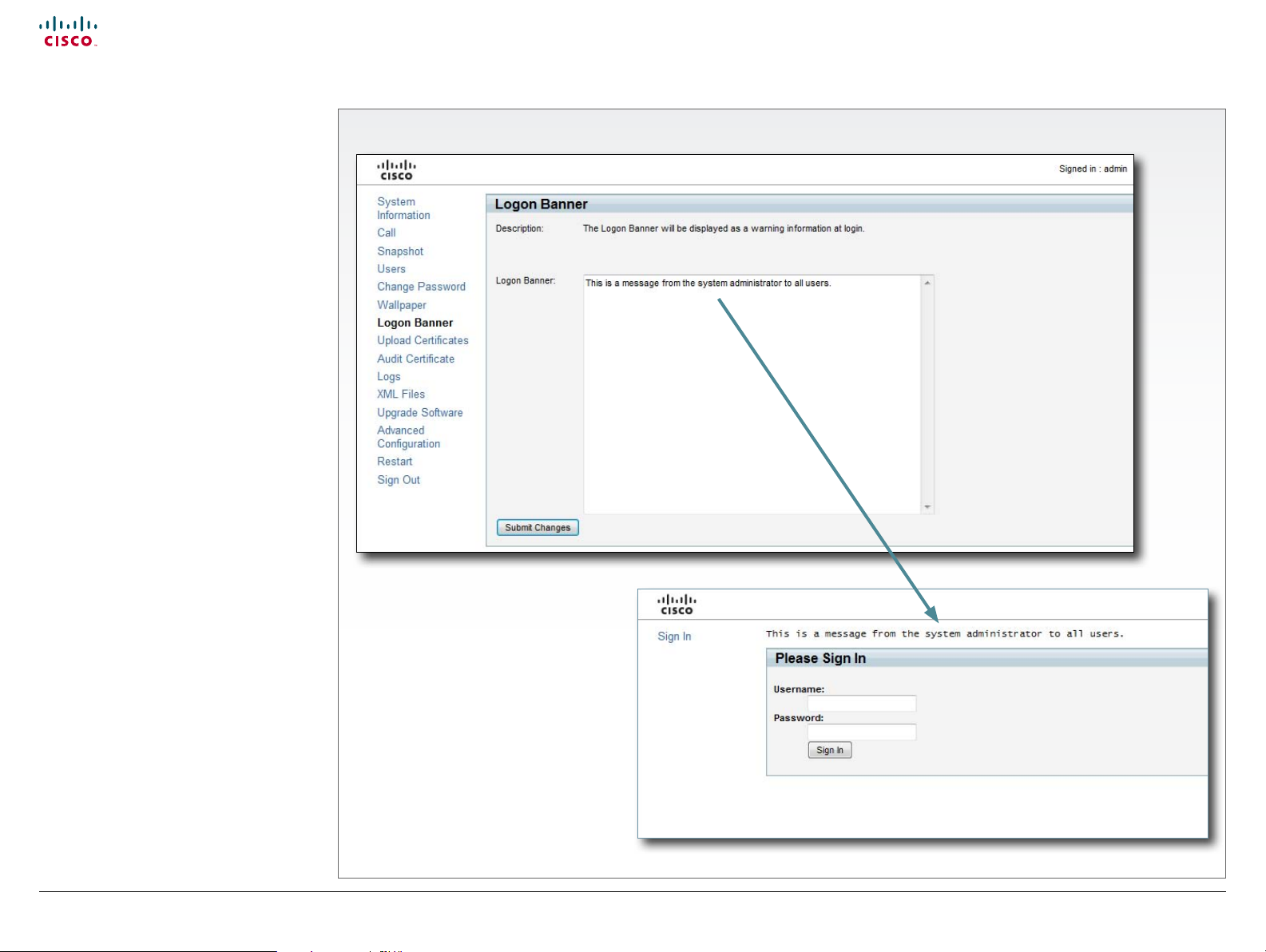
Adding a logon banner
If the system administrator wants to provide
initial information to all users, he can create a
logon banner. A logon banner is a message
that is displayed to the user before signing in.
The message will be shown, whether the
user signs in using the menu system, the web
interface or the command line interface.
The Logon Banner page
Add a logon banner
1. Enter the text message, which you want
2. Press Submit Changes to activate the
D146 35 .05 Prole C90 and Codec C90 Administrator Guide TC4.1, February 2011.
Copyright © 2010-2011 Cisco Systems, Inc. All rights reserved.
to present to the user prior to signing in,
in the Logon Banner text area.
message.
20
www.cisco.com
Page 21
Cisco TelePresence System Codec C90 and Prole 65” Dual using C90 Administrator guide
Contents
Contact us
Introduction
Advanced conguration
Password protection
Web interface
Appendices
Web interface
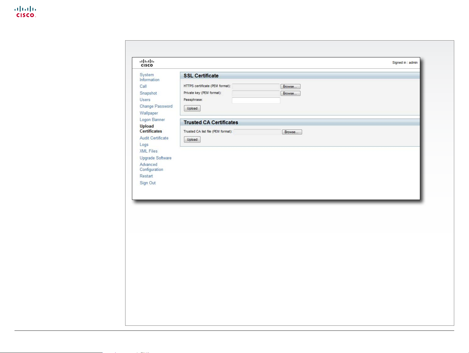
Uploading certicates
The SSL certicate is a text le which veries
the authenticity of your codec. The certicate
may be issued by a certicate authority (CA).
Other parties can check this certicate before
setting up communication with you.
The list of trusted CA certicates is a list
containing the SSL certicates of all parties
that you want your codec to trust.
The Upload Certicates page
Upload the SSL certicate
To install the SSL certicate, you will need the following:
• HTTPS certicate ( .PEM format)
• Private key ( .PEM format)
• Passphrase (optional)
Contact your system administrator to obtain the required les.
• Press Browse... and locate the HTTPS certicate le (.PEM
• Press Browse... and locate the Private key le (.PEM format)
• Enter the Passphrase (optional).
• Press Upload to upload the certicate to the codec.
D146 35 .05 Prole C90 and Codec C90 Administrator Guide TC4.1, February 2011.
Copyright © 2010-2011 Cisco Systems, Inc. All rights reserved.
format).
Upload the Trusted CA certicates list
To install the trusted CA certicates list, you will need the
following:
• Trusted CA list le ( .PEM format).
Contact your system administrator to obtain the required le.
• Press Browse... and locate the le with the Trusted CA list
(.PEM format).
• Press Upload to upload the certicate to the codec.
21
www.cisco.com
Page 22
Cisco TelePresence System Codec C90 and Prole 65” Dual using C90 Administrator guide
Contents
Contact us
Introduction
Advanced conguration
Password protection
Web interface
Appendices
Web interface
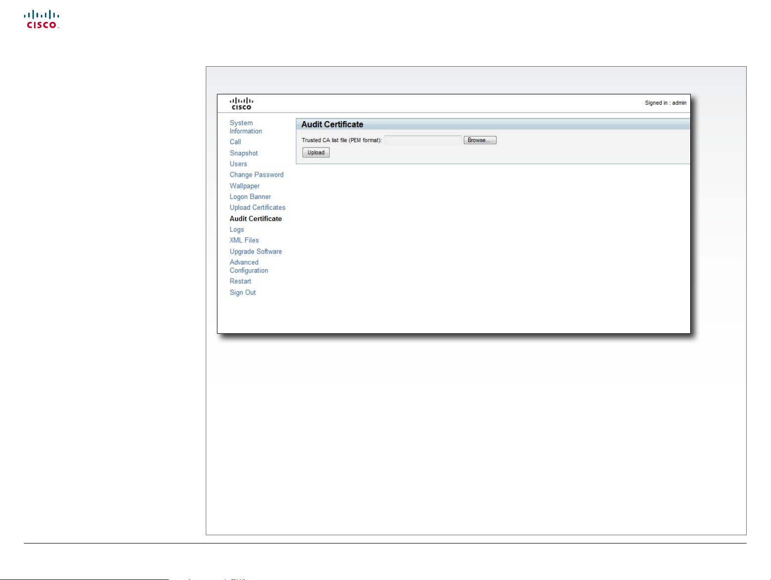
Certicates for secure
logging
If you want to use the ExternalSecure audit
logging mode, you must upload a list of
trusted audit certicates to the codec. This list
covers all audit servers that your codec shall
trust.
In the ExternalSecure audit logging mode
audit logging information will only be sent to
entities holding a valid audit certicate.
NOTE: You should always upload the audit
certicate list before enabling secure audit
logging.
About audit logging
Audit logging records all login activity and
conguration changes on the codec.
Audit logging is disabled by default, and must
be enabled using the on screen menu, the
web interface or the command line interface.
There are three audit logging modes: Internal,
External and ExternalSecure.
The Audit Certicate page
Upload the Audit certicate list
To install the audit certicate, you will
need:
• Audit list le ( .PEM format)
Contact your system administrator to
obtain the required le.
• Press Browse... and locate the le with
• Press Upload to upload the certicate
D146 35 .05 Prole C90 and Codec C90 Administrator Guide TC4.1, February 2011.
Copyright © 2010-2011 Cisco Systems, Inc. All rights reserved.
the audit list le (.PEM format).
to the codec.
Enable secure audit logging
To enable secure audit logging using the
web interface or on screen menu, go to
Advanced Conguration and perform the
following steps:
1. Navigate to Security > Audit > Server
and enter the IP address of the audit
server.
2. Navigate to Security > Audit > Logging
> Mode and set it to ExternalSecure.
22
To enable secure audit logging using
the command line interface, log in to the
codec using SSH or Telnet and enter the
following commands:
1. Security Audit Server Address
<ip add ress>
2. Security Audit Logging Mode
ExternalSecure
www.cisco.com
Page 23
Cisco TelePresence System Codec C90 and Prole 65” Dual using C90 Administrator guide
Contents
Contact us
Introduction
Advanced conguration
Password protection
Web interface
Appendices
Web interface
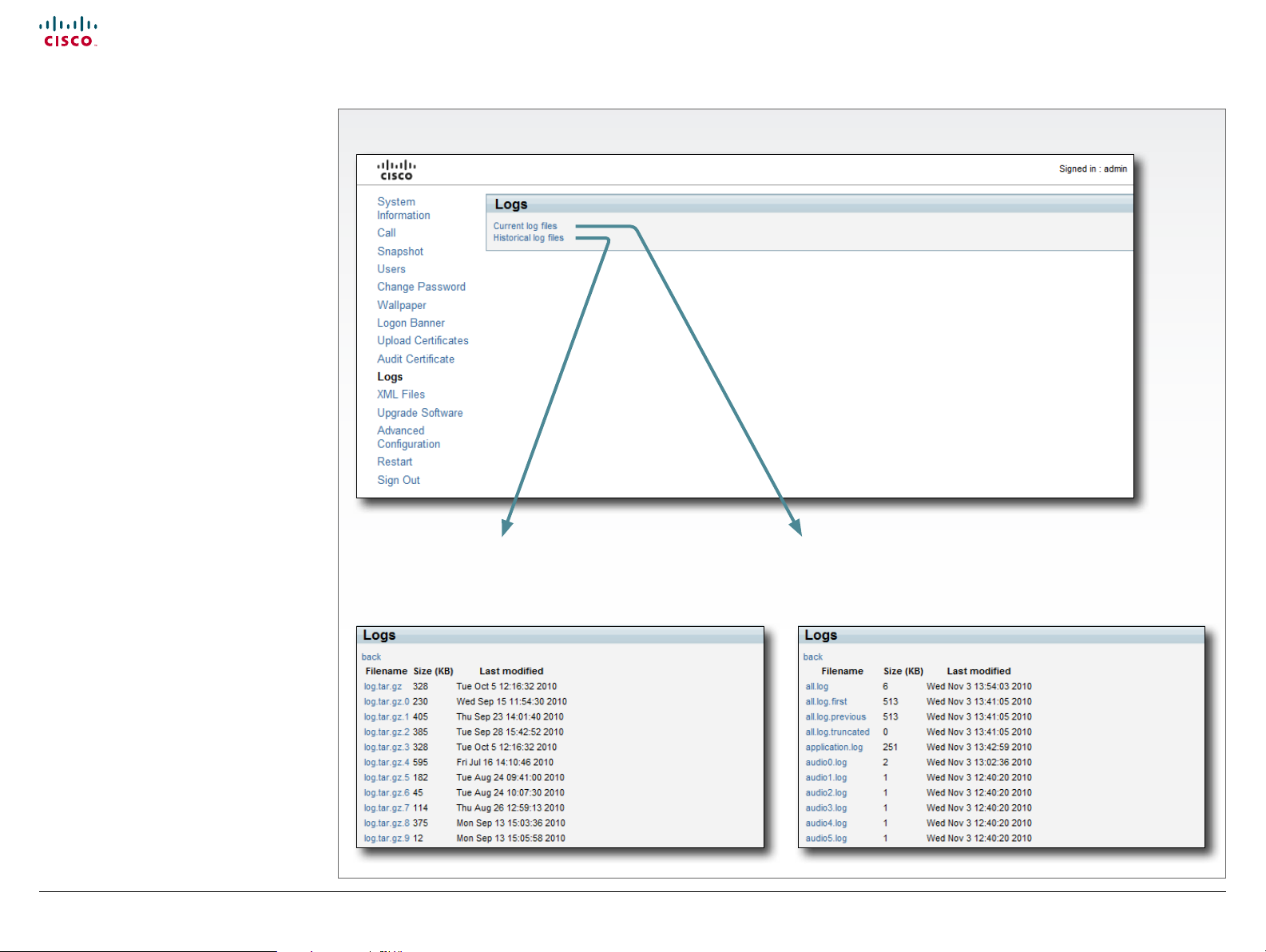
Support log les
The log les are Cisco specic debug les
which may be requested by the Cisco support
organization if you need technical support.
The Logs page
Historical log les
Time stamped historical log les. Select Historical log les,
click on a le and follow the instructions in the dialog box to
save the le.
Current log les
Time stamped event log les. Select Current log les and click
on a text le to view the le. Right click on a le and follow the
instructions in the dialog box to save the le.
D146 35 .05 Prole C90 and Codec C90 Administrator Guide TC4.1, February 2011.
Copyright © 2010-2011 Cisco Systems, Inc. All rights reserved.
23
www.cisco.com
Page 24
Cisco TelePresence System Codec C90 and Prole 65” Dual using C90 Administrator guide
Contents
Contact us
Introduction
Advanced conguration
Password protection
Web interface
Appendices
Web interface
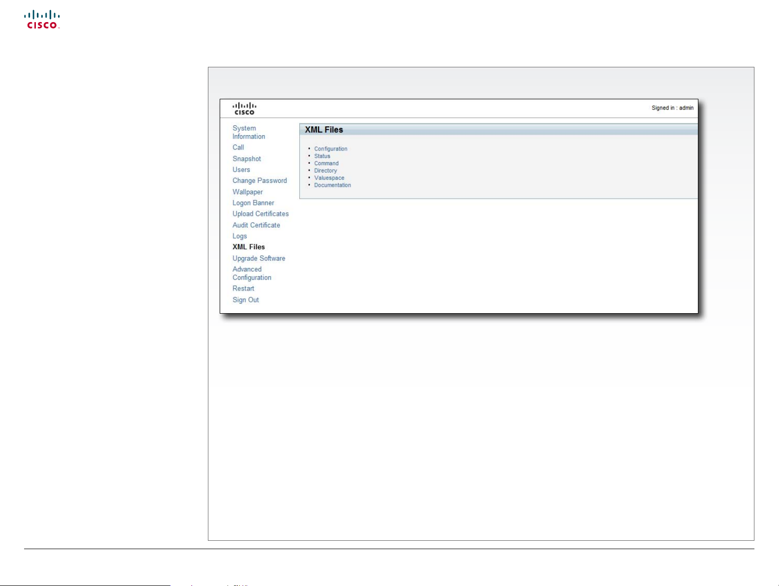
Viewing XML les
The XML les are structured in a hierarchy
building up a database of information about
the codec.
The XML Files page
Conguration
Select Conguration to see an overview of the system
settings, which are controlled from the Advanced conguration
menu, or from the API (Application Programmer Interface).
Status
The Status information is constantly updated by the system to
reect system and process changes. The status information is
normally monitored from the API.
Directory
The Directory le will be described later.
Valuespace
Select Valuespace to see an overview of the value spaces.
Documentation
The Documentation le will be described later.
Command
Select Command to see an overview of the commands
available to instruct the system to perform an action. The
commands are issued from the API.
D146 35 .05 Prole C90 and Codec C90 Administrator Guide TC4.1, February 2011.
Copyright © 2010-2011 Cisco Systems, Inc. All rights reserved.
24
www.cisco.com
Page 25
Cisco TelePresence System Codec C90 and Prole 65” Dual using C90 Administrator guide
Contents
Contact us
Introduction
Advanced conguration
Password protection
Web interface
Appendices
Web interface
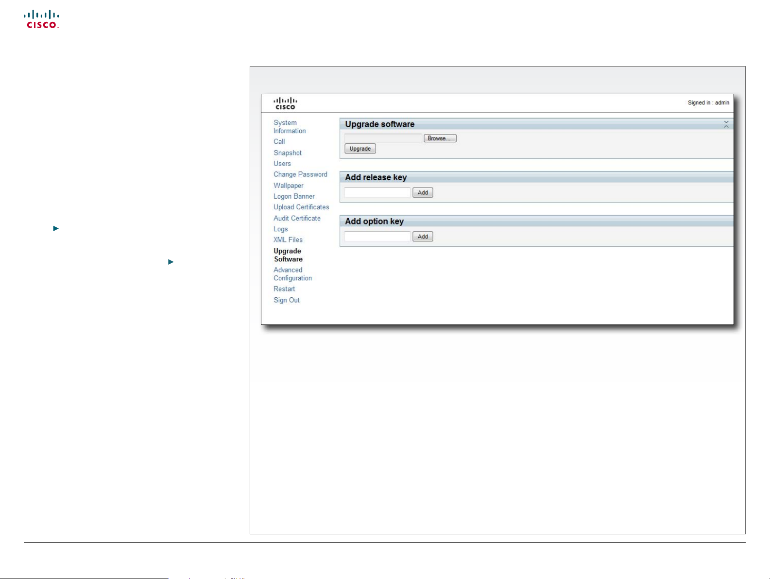
Software upgrade
From this page you can do software upgrades and add a
release key and option keys.
Software versions
The C series codecs are using the TC software.
NOTE: Contact your system administrator if you have
questions about the software version.
Software release notes and upgrade les
Cisco recommends reading the software release notes
before upgrading the software.
Go to:
tsd_products_support_series_home.html
For upgrade software download go to:
com/cisco/software/navigator.html?a=a&i=rpm
Release key
The release key is required to be able to use any of the
released software.
Contact your Cisco representative to obtain the release
key.
Option key
An option key is required to activate any optional
functionality, and you may have several option keys in your
system. The options available are:
• Natural presenter
• Premium resolution
• Multisite
Contact your Cisco representative to obtain the option
key(s).
http://www.cisco.com/en/US/products/ps11422/
http://www.cisco.
The Upgrade Software page
Add the release and option keys
Contact your Cisco representative to obtain the required
key(s). If you will add both a release key and one or more
option keys, the valid procedure will be:
1. Enter the release key and press Add.
The key format: “1TC001-1-0C22E348” (each system will
have a unique key).
2. Enter the option key and press Add.
The key format: “1N000-1-AA7A4A09” (each system will
have a unique key).
3. If you have more than one option key, add the remaining
keys.
Upgrade the software on the codec
4. Before you can start the upgrade you must download the
software upgrade le. The le format: “s52000tc4_0_0.
pkg” (each software version has a unique le name).
5. Press Browse... and select the .PKG le.
6. Press the Upgrade button to start the installation.
7. Leave the system to allow the installation process to
complete. You can follow the progress on this page.
When the upgrade is successfully completed a message
will appear. The installation process may take up to 30
minutes.
D146 35 .05 Prole C90 and Codec C90 Administrator Guide TC4.1, February 2011.
Copyright © 2010-2011 Cisco Systems, Inc. All rights reserved.
25
www.cisco.com
Page 26
Cisco TelePresence System Codec C90 and Prole 65” Dual using C90 Administrator guide
Contents
Contact us
Introduction
Advanced conguration
Password protection
Web interface
Appendices
Web interface
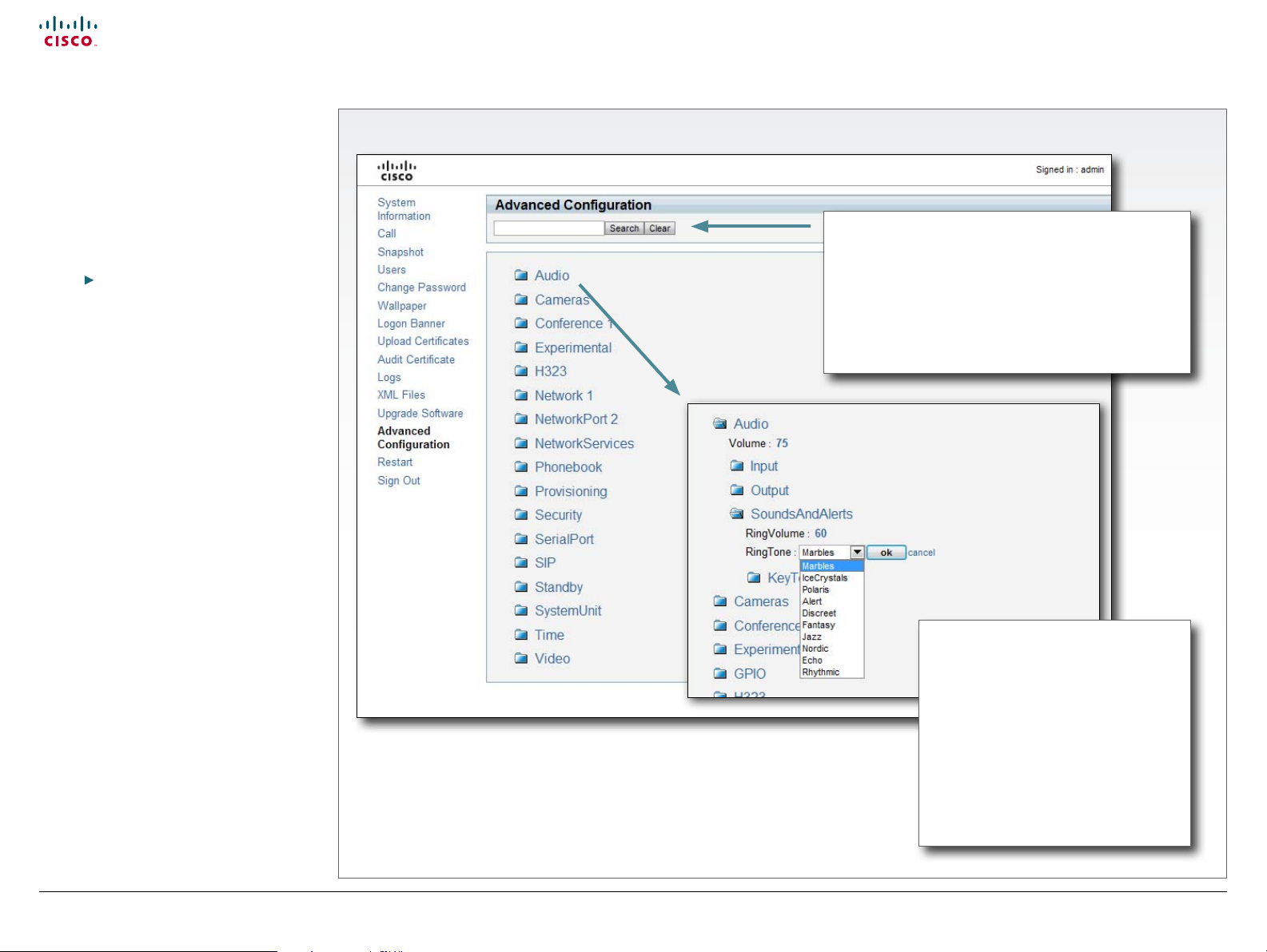
Advanced conguration
The web interface allows for remote
administration of the system.
The Advanced conguration denes the
system settings and are structured in a
hierarchy, making up a database of system
settings.
The system settings are further explained
in the Advanced conguration settings
ch apter.
The Advanced Conguration page
Select a menu item to
see the system settings.
The search functionality
When searching for words such as H323 or SIP, all
settings beginning with these characters, including all
settings below in the hierarchy, will show in the list.
Search: Enter as many characters as needed to get the
desired result and press Search to initiate the search.
Clear: Press Clear to return to the main view.
D146 35 .05 Prole C90 and Codec C90 Administrator Guide TC4.1, February 2011.
Copyright © 2010-2011 Cisco Systems, Inc. All rights reserved.
26
Change the system settings
Edit: To change a value, click on the
value to see the expanded view.
Value space: The value space is
specied, either as a drop down list or
as text, when you edit a value.
OK: Press ok to save the new value.
Cancel: Select cancel to leave without
saving.
www.cisco.com
Page 27

Cisco TelePresence System Codec C90 and Prole 65” Dual using C90 Administrator guide
Contents
Contact us
Introduction
Advanced conguration
Password protection
Web interface
Appendices
Web interface
Restarting the system
Restarting the system takes a few minutes.
The Restart page
Restart the system
Press Restart now.
D146 35 .05 Prole C90 and Codec C90 Administrator Guide TC4.1, February 2011.
Copyright © 2010-2011 Cisco Systems, Inc. All rights reserved.
27
www.cisco.com
Page 28

Cisco TelePresence System Codec C90 and Prole 65” Dual using C90 Administrator guide
Contents
Contact us
Introduction
Advanced conguration
Password protection
Web interface
Appendices
Advanced conguration
Chapter 3
Advanced conguration settings
D146 35 .05 Prole C90 and Codec C90 Administrator Guide TC4.1, February 2011.
Copyright © 2010-2011 Cisco Systems, Inc. All rights reserved.
28
www.cisco.com
Page 29

Cisco TelePresence System Codec C90 and Prole 65” Dual using C90 Administrator guide
Contents
Contact us
Introduction
Advanced conguration
Password protection
Web interface
Appendices
Advanced conguration
Advanced conguration overview
In the following pages you will nd a complete list of the system settings which are congured
from the Advanced Conguration page on the web interface or from the Advanced conguration
menu on screen - open the Home menu and go to: Settings > Administrator settings >
Advanced conguration. The examples show either the default value or an example of a value.
The Audio settings ............................................................................................................. 33
Audio Input HDMI [3, 4] Level ............................................................................................ 33
Audio Input HDMI [3, 4] Mode ............................................................................................ 33
Audio Input HDMI [3..4] VideoAssociation MuteOnInactiveVideo ...................................... 33
Audio Input HDMI [3..4] VideoAssociation VideoInputSource ........................................... 33
Audio Input Line [1..4] Channel ...........................................................................................34
Audio Input Line [1..4] Equalizer ID ..................................................................................... 33
Audio Input Line [1..4] Equalizer Mode ............................................................................... 33
Audio Input Line [1..4] Level ................................................................................................34
Audio Input Line [1..4] LoopSuppression ............................................................................34
Audio Input Line [1..4] Mode ...............................................................................................34
Audio Input Line [1..4] VideoAssociation MuteOnInactiveVideo ........................................ 33
Audio Input Line [1..4] VideoAssociation VideoInputSource .............................................. 33
Audio Input Microphone [1..8] EchoControl Dereverberation .............................................34
Audio Input Microphone [1..8] EchoControl Mode ..............................................................34
Audio Input Microphone [1..8] EchoControl NoiseReduction ..............................................34
Audio Input Microphone [1..8] Equalizer ID .........................................................................34
Audio Input Microphone [1..8] Equalizer Mode .................................................................. 35
Audio Input Microphone [1..8] Level .................................................................................. 35
Audio Input Microphone [1..8] Mode .................................................................................. 35
Audio Input Microphone [1..8] Type ................................................................................... 35
Audio Input Microphone [1..8] VideoAssociation MuteOnInactiveVideo ............................ 35
Audio Input Microphone [1..8] VideoAssociation VideoInputSource ................................. 35
Audio Output HDMI [1, 3] Level .......................................................................................... 35
Audio Output HDMI [1, 3] Mode ......................................................................................... 35
Audio Output Line [1, 3] Type ............................................................................................ 36
Audio Output Line [1..6] Channel ....................................................................................... 36
Audio Output Line [1..6] Equalizer ID .................................................................................. 36
Audio Output Line [1..6] Equalizer Mode ............................................................................ 36
Audio Output Line [1..6] Level ............................................................................................ 36
Audio Output Line [1..6] Mode ........................................................................................... 36
Audio Output Line [2, 4, 5, 6] Type .................................................................................... 36
Audio SoundsAndAlerts KeyTones Mode .......................................................................... 36
Audio SoundsAndAlerts RingTone .....................................................................................37
Audio SoundsAndAlerts RingVolume .................................................................................37
Audio Volume .....................................................................................................................37
The Cameras settings.........................................................................................................37
Cameras Camera [1..7] Backlight ........................................................................................37
Cameras Camera [1..7] Brightness Level ............................................................................37
Cameras Camera [1..7] Brightness Mode ...........................................................................37
Cameras Camera [1..7] DHCP ............................................................................................39
Cameras Camera [1..7] Flip ................................................................................................ 38
Cameras Camera [1..7] Focus Mode ................................................................................. 38
Cameras Camera [1..7] Gamma Level ............................................................................... 38
Cameras Camera [1..7] Gamma Mode .............................................................................. 38
Cameras Camera [1..7] IrSensor ........................................................................................ 38
Cameras Camera [1..7] Mirror ............................................................................................ 38
Cameras Camera [1..7] Whitebalance Level .......................................................................39
Cameras Camera [1..7] Whitebalance Mode ..................................................................... 38
Cameras PowerLine Frequency .........................................................................................37
The Conference settings ....................................................................................................39
Conference [1..1] AutoAnswer Delay ..................................................................................39
Conference [1..1] AutoAnswer Mode ..................................................................................39
Conference [1..1] AutoAnswer Mute ...................................................................................39
Conference [1..1] DefaultCall Protocol ............................................................................... 40
Conference [1..1] DefaultCall Rate ..................................................................................... 40
Conference [1..1] DoNotDisturb Mode ............................................................................... 40
Conference [1..1] Encryption Mode .................................................................................... 40
Conference [1..1] FarEndControl Mode .............................................................................. 40
Conference [1..1] FarEndControl SignalCapability ............................................................. 40
Conference [1..1] IncomingMultisiteCall Mode ....................................................................39
Conference [1..1] MaxReceiveCallRate ...............................................................................41
Conference [1..1] MaxTransmitCallRate ............................................................................. 40
Conference [1..1] MicUnmuteOnDisconnect ...................................................................... 40
Conference [1..1] PacketLossResilience Mode ................................................................... 41
Conference [1..1] VideoBandwidth MainChannel Weight ...................................................41
Conference [1..1] VideoBandwidth Mode ...........................................................................41
Conference [1..1] VideoBandwidth PresentationChannel Weight .......................................41
The GPIO settings............................................................................................................... 42
GPIO Pin [1..4] Mode ...........................................................................................................42
D146 35 .05 Prole C90 and Codec C90 Administrator Guide TC4.1, February 2011.
Copyright © 2010-2011 Cisco Systems, Inc. All rights reserved.
29
www.cisco.com
Page 30

Cisco TelePresence System Codec C90 and Prole 65” Dual using C90 Administrator guide
Contents
Contact us
Introduction
Advanced conguration
Password protection
Web interface
Appendices
Advanced conguration
The H323 settings .............................................................................................................. 42
H323 NAT Address .............................................................................................................42
H323 NAT Mode .................................................................................................................42
H323 Prole [1..1] Authentication LoginName ................................................................... 43
H323 Prole [1..1] Authentication Mode .............................................................................42
H323 Prole [1..1] Authentication Password ...................................................................... 43
H323 Prole [1..1] CallSetup Mode .................................................................................... 43
H323 Prole [1..1] Gatekeeper Address ............................................................................. 43
H323 Prole [1..1] Gatekeeper Discovery .......................................................................... 43
H323 Prole [1..1] H323Alias E164 .................................................................................... 43
H323 Prole [1..1] H323Alias ID ......................................................................................... 43
H323 Prole [1..1] PortAllocation ....................................................................................... 44
The Network settings .........................................................................................................44
Network [1..1] Assignment ................................................................................................. 44
Network [1..1] DNS Domain Name ..................................................................................... 44
Network [1..1] DNS Server [1..5] Address .......................................................................... 44
Network [1..1] IEEE8021X AnonymousIdentity ....................................................................47
Network [1..1] IEEE8021X Eap Md5 .....................................................................................47
Network [1..1] IEEE8021X Eap Peap ....................................................................................47
Network [1..1] IEEE8021X Eap TTLS ....................................................................................47
Network [1..1] IEEE8021X Identity ...................................................................................... 46
Network [1..1] IEEE8021X Mode ......................................................................................... 46
Network [1..1] IEEE8021X Password .................................................................................. 46
Network [1..1] IPStack ........................................................................................................ 44
Network [1..1] IPv4 Address ............................................................................................... 45
Network [1..1] IPv4 Gateway .............................................................................................. 45
Network [1..1] IPv4 SubnetMask ........................................................................................ 45
Network [1..1] IPv6 Address ............................................................................................... 45
Network [1..1] IPv6 Assignment ......................................................................................... 45
Network [1..1] IPv6 DHCPOtions ........................................................................................ 45
Network [1..1] IPv6 Gateway .............................................................................................. 45
Network [1..1] MTU ..............................................................................................................47
Network [1..1] QoS Diserv Audio ..................................................................................... 46
Network [1..1] QoS Diserv Data ....................................................................................... 46
Network [1..1] QoS Diserv Signalling ............................................................................... 46
Network [1..1] QoS Diserv Video ..................................................................................... 46
Network [1..1] QoS Mode ................................................................................................... 45
Network [1..1] RemoteAccess Allow ...................................................................................47
Network [1..1] Speed ...........................................................................................................47
Network [1..1] TracControl Mode .....................................................................................47
Network [1..1] VLAN Voice Mode ....................................................................................... 48
Network [1..1] VLAN Voice Priority ..................................................................................... 48
Network [1..1] VLAN Voice VlanId ...................................................................................... 48
D146 35 .05 Prole C90 and Codec C90 Administrator Guide TC4.1, February 2011.
Copyright © 2010-2011 Cisco Systems, Inc. All rights reserved.
The NetworkPort settings ................................................................................................... 48
NetworkPort [2] Mode ....................................................................................................... 48
30
www.cisco.com
Page 31

Cisco TelePresence System Codec C90 and Prole 65” Dual using C90 Administrator guide
Contents
Contact us
Introduction
Advanced conguration
Password protection
Web interface
Appendices
Advanced conguration
The NetworkServices settings ............................................................................................49
NetworkServices H323 Mode ........................................................................................... 49
NetworkServices HTTP Mode ........................................................................................... 49
NetworkServices HTTPS Mode ........................................................................................ 49
NetworkServices HTTPS VerifyClientCerticate .............................................................. 49
NetworkServices HTTPS VerifyServerCerticate ............................................................. 49
NetworkServices Multiway Address .................................................................................. 49
NetworkServices Multiway Protocol .................................................................................. 49
NetworkServices NTP Address ......................................................................................... 50
NetworkServices NTP Mode ............................................................................................. 50
NetworkServices SIP Mode .............................................................................................. 50
NetworkServices SNMP CommunityName ....................................................................... 50
NetworkServices SNMP Host [1..3] Address ..................................................................... 50
NetworkServices SNMP Mode .......................................................................................... 50
NetworkServices SNMP SystemContact ........................................................................... 51
NetworkServices SNMP SystemLocation .......................................................................... 51
NetworkServices SSH AllowPublicKey...............................................................................51
NetworkServices SSH Mode ..............................................................................................51
NetworkServices Telnet Mode ...........................................................................................51
The Phonebook settings ..................................................................................................... 52
Phonebook Server [1..1] ID .................................................................................................52
Phonebook Server [1..1] Type .............................................................................................52
Phonebook Server [1..1] URL ..............................................................................................52
The Provisioning settings ...................................................................................................52
Provisioning ExternalManager Address ............................................................................. 53
Provisioning ExternalManager Domain .............................................................................. 53
Provisioning ExternalManager Path ................................................................................... 53
Provisioning ExternalManager Protocol ............................................................................. 53
Provisioning HttpMethod ....................................................................................................52
Provisioning LoginName .....................................................................................................52
Provisioning Mode ..............................................................................................................52
Provisioning Password .......................................................................................................52
The SerialPort settings ....................................................................................................... 54
SerialPort BaudRate .......................................................................................................... 54
SerialPort LoginRequired ................................................................................................... 54
SerialPort Mode ................................................................................................................. 54
The SIP settings ................................................................................................................. 55
SIP Prole [1..1] Authentication [1..1] LoginName ............................................................... 55
SIP Prole [1..1] Authentication [1..1] Password ................................................................. 55
SIP Prole [1..1] DefaultTransport ....................................................................................... 55
SIP Prole [1..1] Outbound ................................................................................................. 55
SIP Prole [1..1] Proxy [1..4] Address ................................................................................. 55
SIP Prole [1..1] Proxy [1..4] Discovery ............................................................................... 55
SIP Prole [1..1] TlsVerify ................................................................................................... 55
SIP Prole [1..1] Type ......................................................................................................... 56
SIP Prole [1..1] URI............................................................................................................ 56
The Standby settings .......................................................................................................... 56
Standby BootAction........................................................................................................... 56
Standby Control ................................................................................................................. 56
Standby Delay ................................................................................................................... 56
Standby StandbyAction ......................................................................................................57
Standby WakeupAction ......................................................................................................57
The SystemUnit settings ..................................................................................................... 57
SystemUnit CallLogging Mode .......................................................................................... 58
SystemUnit ContactInfo Type .............................................................................................57
SystemUnit IrSensor Mode ............................................................................................... 58
SystemUnit MenuLanguage ...............................................................................................57
SystemUnit Name ...............................................................................................................57
The Time settings ............................................................................................................... 58
Time DateFormat ............................................................................................................... 58
Time TimeFormat .............................................................................................................. 58
Time Zone ..........................................................................................................................59
The Security settings .......................................................................................................... 53
Security Audit Logging Mode ............................................................................................ 54
Security Audit OnError Action ........................................................................................... 53
Security Audit Server Address .......................................................................................... 53
Security Audit Server Port ................................................................................................. 53
Security Session InactivityTimeout .................................................................................... 54
D146 35 .05 Prole C90 and Codec C90 Administrator Guide TC4.1, February 2011.
Copyright © 2010-2011 Cisco Systems, Inc. All rights reserved.
31
www.cisco.com
Page 32

Cisco TelePresence System Codec C90 and Prole 65” Dual using C90 Administrator guide
Contents
Contact us
Introduction
Advanced conguration
Password protection
Web interface
Appendices
Advanced conguration
The Video settings ..............................................................................................................59
Video AllowWebSnapshots ............................................................................................... 64
Video DefaultPresentationSource ......................................................................................59
Video Input DVI [3, 5] Type .................................................................................................59
Video Input Source [1..5] CameraControl CameraId ......................................................... 60
Video Input Source [1..5] CameraControl Mode ................................................................ 60
Video Input Source [1..5] Name ..........................................................................................59
Video Input Source [1..5] OptimalDenition Prole .............................................................61
Video Input Source [1..5] OptimalDenition Threshold60fps ..............................................61
Video Input Source [1..5] Quality ........................................................................................61
Video Input Source [1..5] Type ........................................................................................... 60
Video Input Source [1] Connector ..................................................................................... 60
Video Input Source [2] Connector ..................................................................................... 60
Video Input Source [3] Connector ..................................................................................... 60
Video Input Source [4] Connector ..................................................................................... 60
Video Input Source [5] Connector ..................................................................................... 60
Video Layout LocalLayoutFamily ........................................................................................62
Video Layout RemoteLayoutFamily ....................................................................................62
Video Layout ScaleToFrame ...............................................................................................62
Video Layout ScaleToFrameThreshold ...............................................................................62
Video Layout Scaling .......................................................................................................... 61
Video MainVideoSource .....................................................................................................62
Video Monitors .................................................................................................................. 63
Video OSD InputMethod Cyrillic ........................................................................................ 63
Video OSD InputMethod InputLanguage ........................................................................... 63
Video OSD LoginRequired ................................................................................................. 64
Video OSD Mode ............................................................................................................... 63
Video OSD MyContactsExpanded .................................................................................... 63
Video OSD Output ............................................................................................................. 63
Video OSD TodaysBookings .............................................................................................. 63
Video Output Composite [5] MonitorRole .......................................................................... 65
Video Output Composite [5] OverscanLevel ..................................................................... 65
Video Output Composite [5] Resolution ............................................................................ 65
Video Output DVI [2, 4] MonitorRole .................................................................................. 64
Video Output DVI [2, 4] OverscanLevel ............................................................................. 65
Video Output DVI [2, 4] Resolution .................................................................................... 65
Video Output HDMI [1, 3] MonitorRole ............................................................................... 64
Video Output HDMI [1, 3] OverscanLevel .......................................................................... 64
Video Output HDMI [1, 3] Resolution ................................................................................. 64
Video Selfview ................................................................................................................... 65
Video SelfviewPosition .......................................................................................................62
Video WallPaper ................................................................................................................ 66
The Experimental settings .................................................................................................. 66
Experimental Audio Input Microphone [1..8] Channel ........................................................ 68
Experimental Audio Input Microphone [1..8] EchoControl HighPassFilter ......................... 68
Experimental Audio MicrophoneReinforcement AGC ....................................................... 68
Experimental Audio MicrophoneReinforcement Gain ........................................................ 68
Experimental Audio MicrophoneReinforcement Input Microphone [1..8] Mode ................ 68
Experimental Audio MicrophoneReinforcement Output Line [1..6] Mode...........................69
Experimental Audio Panning MaxAngle .............................................................................69
Experimental Audio Panning Mode ....................................................................................69
Experimental Audio Panning MonitorLeft ...........................................................................69
Experimental Audio Panning MonitorRight .........................................................................69
Experimental AudioTracking Camera [1..7] Mode .............................................................. 66
Experimental BrightnessGradient Camera [1..7] Level ...................................................... 66
Experimental BrightnessGradient Camera [1..7] Mode ...................................................... 66
Experimental CapsetFilter ..................................................................................................67
Experimental Conference [1..1] PacketLossResilience ForwardErrorCorrection ................67
Experimental Conference [1..1] PacketLossResilience RateAdaption.................................67
Experimental CustomSoftbuttons State [1..2] Softbutton [1..5] Type ..................................67
Experimental CustomSoftbuttons State [1..2] Softbutton [1..5] Value ................................67
Experimental NetworkServices UPnP Mode ..................................................................... 68
Experimental NetworkServices UPnP Timeout ................................................................. 68
Experimental SoftwareUpgrade Mode ...............................................................................67
Experimental SoftwareUpgrade ServerAddress ................................................................67
Experimental SystemUnit Controller Address ....................................................................67
Experimental SystemUnit MenuType ..................................................................................69
D146 35 .05 Prole C90 and Codec C90 Administrator Guide TC4.1, February 2011.
Copyright © 2010-2011 Cisco Systems, Inc. All rights reserved.
32
www.cisco.com
Page 33

Cisco TelePresence System Codec C90 and Prole 65” Dual using C90 Administrator guide
Contents
Contact us
Introduction
Advanced conguration
Password protection
Web interface
Appendices
Advanced conguration
The Audio settings
Audio Input HDMI [3, 4] Mode
Determine if the audio channels on the HDMI input shall be enabled. The HDMI input 3 and 4 has two
audio channels.
Requires user role: ADMIN
Value space: <On/Off>
On: Enable the audio channels on the HDMI input.
O: Disable the audio channels on the HDMI input.
Ex a mple: Audio Input HDMI 3 Mode: On
Audio Input HDMI [3, 4] Level
Dene the audio level of the HDMI input connector, in steps of 1dB.
See the Audio Level tables in the Physical Interfaces Guide for the codec for a complete overview of
the menu values represented in dB.
Requires user role: ADMIN
Value space: <-24..0>
Range: Select a value from -24 to 0dB.
Ex a mple: Audio Input HDMI 3 Level: 0
Audio Input HDMI [3..4] VideoAssociation MuteOnInactiveVideo
Enable association of a video source to a HDMI audio input.
Requires user role: ADMIN
Value space: <On/Off>
On: A video source is associated, and the audio will be muted if the associated video source is not
displayed.
O: No video source is associated.
Ex a mple: Audio Input HDMI 3 VideoAssociation MuteOnInactiveVideo: Off
Audio Input HDMI [3..4] VideoAssociation VideoInputSource
Select the associated video input source.
Requires user role: ADMIN
Value space: <1/2/ 3/4/5>
Range: Select one of the ve video input sources.
Ex a mple: Audio Input HDMI 3 VideoAssociation VideoInputSource: 1
Audio Input Line [1..4] Equalizer ID
Select the audio input line equalizer ID.
Requires user role: ADMIN
Value space: <1..8>
Range: Select EqualizerID 1 to 8.
Ex a mple: Audio Input Line 1 Eq ualizer ID: 1
Audio Input Line [1..4] Equalizer Mode
Set the audio input line equalizer mode.
Requires user role: ADMIN
Value space: <On/Off>
On: Enable the equalizer for the audio input line.
O: No equalizer.
Ex a mple: Audio Input Line 1 Eq ualizer Mode: Off
Audio Input Line [1..4] VideoAssociation MuteOnInactiveVideo
Enable association of a video source to a Line audio input.
Requires user role: ADMIN
Value space: <On/Off>
On: A video source is associated, and the audio will be muted if the associated video source is not
displayed.
O: No video source is associated.
Ex a mple: Audio Input Line 1 VideoAssociation MuteOnInactiveVideo: Off
Audio Input Line [1..4] VideoAssociation VideoInputSource
Select the associated video input source.
Requires user role: ADMIN
Value space: <1/2/ 3/4/5>
Range: Select one of the ve video input sources.
Ex a mple: Audio Input Line 1 VideoAssociation VideoInputSource: 1
D146 35 .05 Prole C90 and Codec C90 Administrator Guide TC4.1, February 2011.
Copyright © 2010-2011 Cisco Systems, Inc. All rights reserved.
33
www.cisco.com
Page 34

Cisco TelePresence System Codec C90 and Prole 65” Dual using C90 Administrator guide
Contents
Contact us
Introduction
Advanced conguration
Password protection
Web interface
Appendices
Advanced conguration
Audio Input Line [1..4] Channel
Dene whether the Audio Line input is a mono signal or part of a multichannel signal.
Requires user role: ADMIN
Value space: <Left/Right/Mo no>
Left: The Audio Line input signal is the left channel of a stereo signal.
Right: The Audio Line input signal is the right channel of a stereo signal.
Mono: The Audio Line input signal is a mono signal.
Ex a mple: Audio Input 1 Channel: Left
Audio Input Line [1..4] Level
Dene the audio level of the Line input connector, in steps of 1dB.
See the Audio Level tables in the Physical Interfaces Guide for the codec for a complete overview of
the menu values represented in dB.
Requires user role: ADMIN
Value space: <0..24>
Range: Select a value from 0 to 24dB.
Ex a mple: Audio Input Line 1 Level: 10
Audio Input Line [1..4] LoopSuppression
The loop suppression functionality detects whether a delayed signal loop is present from an audio
Line output to an audio Line input on the codec. If a loop is detected the unwanted feedback is
suppressed.
NOTE: Only loops between line output 3 and line input 3, and between line output 4 and line input 4
are suppressible.
Requires user role: ADMIN
Value space: <On/Off>
On: Activate Loop Suppression.
O: Deactivate Loop Suppression.
Ex a mple: Audio Input Line 3 LoopSuppression: On
Audio Input Microphone [1..8] EchoControl Mode
The echo canceller continuously adjusts itself to the audio characteristics of the room and
compensate for any changes it detects in the audio environment. If the changes in the audio
conditions are very signicant the echo canceller may take a second or two to re-adjust.
Requires user role: ADMIN
Value space: <On/Off>
On: Echo Control is normally set to On to prevent the far end from hearing their own audio. Once
selected, echo cancellation is active at all times.
O: Echo Control should be switched O if external echo cancellation or playback equipment is
used.
Ex a mple: Audio Input Microphone 1 EchoControl Mode: On
Audio Input Microphone [1..8] EchoControl NoiseReduction
The system has a built-in noise reduction which reduces constant background noise (e.g. noise from
air-conditioning systems, cooling fans etc.). In addition, a high pass lter (Humlter) reduces very low
frequency noise. NOTE: Requires the Echo Control Mode to be enabled for the microphone.
Requires user role: ADMIN
Value space: <On/Off>
On: The Noise Reduction should be enabled in the presence of low frequency noise.
O: Turn o the Noise Reduction.
Ex a mple: Audio Input Microphone 1 EchoControl NoiseReduction: On
Audio Input Microphone [1..8] EchoControl Dereverberation
The system has built-in signal processing to reduce the eect of room reverberation. NOTE: Requires
the Echo Control Mode to be enabled for the microphone.
Requires user role: ADMIN
Value space: <On/Off>
On: Turn on the dereverberation.
O: Turn o the dereverberation.
Ex a mple: Audio Input Microphone 1 EchoControl Dereverberation: On
Audio Input Line [1..4] Mode
Set the audio input line mode.
Requires user role: ADMIN
Value space: <On/Off>
On: Enable the Audio Line input.
O: Disable the Audio Line input.
Ex a mple: Audio Input Line 1 Mode: On
D146 35 .05 Prole C90 and Codec C90 Administrator Guide TC4.1, February 2011.
Copyright © 2010-2011 Cisco Systems, Inc. All rights reserved.
Audio Input Microphone [1..8] Equalizer ID
Select the audio input microphone equalizer ID.
Requires user role: ADMIN
Value space: <1..14>
Range: Select Equalizer ID 1 to 14.
Ex a mple: Audio Input Microphone 1 Equalizer ID: 1
34
www.cisco.com
Page 35

Cisco TelePresence System Codec C90 and Prole 65” Dual using C90 Administrator guide
Contents
Contact us
Introduction
Advanced conguration
Password protection
Web interface
Appendices
Advanced conguration
Audio Input Microphone [1..8] Equalizer Mode
Set the audio input microphone equalizer mode.
Requires user role: ADMIN
Value space: <On/Off>
On: Enable the equalizer for the audio input microphone.
O: No equalizer.
Ex a mple: Audio Input Microphone 1 Equalizer Mode: Off
Audio Input Microphone [1..8] VideoAssociation MuteOnInactiveVideo
Enable association of a video source to a microphone audio input.
Requires user role: ADMIN
Value space: <On/Off>
On: A video source is associated, and the audio will be muted if the associated video source is not
displayed.
O: No video source is associated.
Ex a mple: Audio Input Microphone 1 VideoAssociation MuteOnInactiveVideo: On
Audio Input Microphone [1..8] VideoAssociation VideoInputSource
Select the associated video input source.
Requires user role: ADMIN
Value space: <1/2/ 3/4/5>
Range: Select one of the ve video input sources.
Ex a mple: Audio Input Microphone 1 VideoAssociation VideoInputSource: 1
Audio Input Microphone [1..8] Level
Dene the audio level of the Microphone input connector, in steps of 1dB.
See the Audio Level tables in the Physical Interfaces Guide for the codec for a complete overview of
the menu values represented in dB.
Requires user role: ADMIN
Value space: <0..24>
Range: Select a value from 0 to 24dB.
Ex a mple: Audio Input Microphone 1 Level: 15
Audio Input Microphone [1..8] Mode
Set the audio input microphone mode.
Requires user role: ADMIN
Value space: <On/Off>
On: Enable the microphone connector.
O: Disable the microphone connector.
Ex a mple: Audio Input Microphone 1 Mode: On
Audio Input Microphone [1..8] Type
The microphone connectors are intended for electret type microphones. The microphone connector
can be set to line or microphone mode.
Requires user role: ADMIN
Value space: <Microphone/Line>
Microphone: Select Microphone when you have 48 V Phantom voltage and the pre-amplication
is On.
Line: Select Line when you have a standard balanced line input. The phantom voltage and preamplication is O.
Ex a mple: Audio Input Microphone 1 Type: Line
Audio Output HDMI [1, 3] Level
Dene the output level of the HDMI output connector, in steps of 1dB.
See the Audio Level tables in the Physical Interfaces Guide for the codec for a complete overview of
the menu values represented in dB.
Requires user role: ADMIN
Value space: <-24..0>
Range: Select a value from -24 to 0dB.
Ex a mple: Audio Output HDMI 1 Level: 0
Audio Output HDMI [1, 3] Mode
Determine if the audio channel on the HDMI output connector shall be enabled.
Requires user role: ADMIN
Value space: <On/Off>
On: Enable the audio channel on the HDMI output.
O: Disable the audio channel on the HDMI output.
Ex a mple: Audio Output HDMI 1 Mode: On
D146 35 .05 Prole C90 and Codec C90 Administrator Guide TC4.1, February 2011.
Copyright © 2010-2011 Cisco Systems, Inc. All rights reserved.
35
www.cisco.com
Page 36

Cisco TelePresence System Codec C90 and Prole 65” Dual using C90 Administrator guide
Contents
Contact us
Introduction
Advanced conguration
Password protection
Web interface
Appendices
Advanced conguration
Audio Output Line [1..6] Channel
Dene whether the Audio Line output is a mono signal or part of a multichannel signal.
Requires user role: ADMIN
Value space: <Left/Right/Mo no>
Left: The Audio Line output signal is the left channel of a stereo signal.
Right: The Audio Line output signal is the right channel of a stereo signal.
Mono: The Audio Line output signal is a mono signal.
Ex a mple: Audio Output Line 1 Channel: left
Audio Output Line [1..6] Equalizer ID
Select the audio output line equalizer ID.
Requires user role: ADMIN
Value space: <1..8>
Range: Select EqualizerID 1 to 8.
Ex a mple: Audio Output Line 1 Equalizer ID: 1
Audio Output Line [1..6] Equalizer Mode
Set the audio output line equalizer mode.
Requires user role: ADMIN
Value space: <On/Off>
On: Enable the equalizer for the audio output line.
O: No equalizer.
Ex a mple: Audio Output Line 1 Equalizer Mode: Off
Audio Output Line [1..6] Mode
Set the audio output line mode.
Requires user role: ADMIN
Value space: <On/Off>
On: Enable the Audio Line output.
O: Disable the Audio Line output.
Ex a mple: Audio Output Line 1 Mode: On
Audio Output Line [1, 3] Type
Determine if the Audio Line output will be analog or digital type output. The digital output on the Cisco
TelePresence Prole systems are identied as DNAM (Digital Natural Audio Modeule).
Requires user role: ADMIN
Value space: <Auto/SPDIF>
Auto: If a Digital NAM is detected then SPDIF mode will be selected, otherwise analog mode will
be selected.
SPDIF: Set to SPDIF when you want the line output to be in digital mode.
Ex a mple: Audio Output Line 1 Type: Auto
Audio Output Line [2, 4, 5, 6] Type
Line output 2, 4, 5, 6 are dedicated analog outputs, hence type can be set to analog only.
Requires user role: ADMIN
Value space: <Analog>
Analog: Can be set to analog only.
Ex a mple: Audio Output Line 2 Type: Analog
Audio Output Line [1..6] Level
Dene the output level of the Audio Output Line connector, in steps of 1dB.
See the Audio Level tables in the Physical Interfaces Guide for the codec for a complete overview of
the menu values represented in dB.
Requires user role: ADMIN
Value space: <-24..0>
Range: Select a value from -24 to 0dB.
Ex a mple: Audio Output Line 1 Level: -10
D146 35 .05 Prole C90 and Codec C90 Administrator Guide TC4.1, February 2011.
Copyright © 2010-2011 Cisco Systems, Inc. All rights reserved.
Audio SoundsAndAlerts KeyTones Mode
The system can produce a sound every time a key on the remote control is pressed.
Requires user role: USER
Value space: <On/Off>
On: There will be a sound indicator when pressing keys on the remote control.
O: The remote control Key Tones is switched o.
Ex a mple: Audio SoundsAndAlerts KeyTones Mode: Off
36
www.cisco.com
Page 37

Cisco TelePresence System Codec C90 and Prole 65” Dual using C90 Administrator guide
Contents
Contact us
Introduction
Advanced conguration
Password protection
Web interface
Appendices
Advanced conguration
Audio SoundsAndAlerts RingTone
Select the ring tone for incoming calls.
Requires user role: USER
Value space: <Marbles/IceCrystals/Polaris/Alert/Discrete/Fantasy/Jazz/Nordic/
Ec ho/R hy th m ic>
Range: Select a tone from the list of ring tones.
Ex a mple: Audio SoundsAndAlerts RingTone: Jazz
Audio SoundsAndAlerts RingVolume
Set the ring tone volume for an incoming call. The value goes in steps of 5 from 0 to 100 (from
-34.5dB to 15dB). Volume 0 = O.
Requires user role: USER
Value space: <0..100>
Range: Select a value from 0 to 100.
Ex a mple: Audio SoundsAndAlerts RingVolume: 50
Audio Volume
Set the volume on the loudspeaker. The value goes in steps of 5 from 0 to 100 (from -34.5dB to
15dB). Volume 0 = O.
Requires user role: USER
Value space: <0..100>
Range: Select a value from 0 to 100.
Ex a mple: Audio Volume: 70
The Cameras settings
Cameras PowerLine Frequency
Applies to cameras supporting PowerLine frequency anti-ickering, i.e PrecisionHD 1080p cameras.
Requires user role: ADMIN
Value space: <Auto/50Hz/60Hz>
Auto: Set to Auto to enable power frequency auto detection in the camera.
50Hz/60Hz: Set to 50Hz or 60Hz.
Ex a mple: Cameras PowerLine Frequency: Auto
Cameras Camera [1..7] Backlight
The backlight functionality compensates for lights shining directly at the camera (usually the sun
entering the window) to avoid a too dark image from the room.
Requires user role: ADMIN
Value space: <On/Off>
On: Turn on the camera backlight.
O: Turn o the camera backlight.
Ex a mple: Cameras Camera 1 Backlight: Off
Cameras Camera [1..7] Brightness Mode
Set the camera brightness mode.
Requires user role: ADMIN
Value space: <Auto/Manual>
Auto: The camera brightness is automatically set by the system.
Manual: Enable manual control of the camera brightness, e.g. the level of the brightness level
setting will be used for the camera.
Ex a mple: Cameras Camera 1 Brightness Mode: Auto
D146 35 .05 Prole C90 and Codec C90 Administrator Guide TC4.1, February 2011.
Copyright © 2010-2011 Cisco Systems, Inc. All rights reserved.
Cameras Camera [1..7] Brightness Level
Set the brightness level. NOTE: Requires the Brightness Mode to be set to Manual.
Requires user role: ADMIN
Value space: <1..31>
Range: Select a value from 1 to 31.
Ex a mple: Cameras Camera 1 Brightness Level: 1
37
www.cisco.com
Page 38

Cisco TelePresence System Codec C90 and Prole 65” Dual using C90 Administrator guide
Contents
Contact us
Introduction
Advanced conguration
Password protection
Web interface
Appendices
Advanced conguration
Cameras Camera [1..7] Flip
With Flip mode (vertical ip) you can ip the image upside down.
Requires user role: ADMIN
Value space: <Au to/O n/O ff>
Auto: When the camera is placed upside down the image is automatically ipped upside down.
Use this setting with cameras that can be mounted upside down, and that can auto detect that the
camera is mounted upside down.
On: When enabled the video on screen is ipped. This setting is used with cameras that can be
mounted upside down, but cannot auto detect that the camera is mounted upside down.
O: Display the video on screen the normal way.
Ex a mple: Cameras Camera 1 Flip: Off
Cameras Camera [1..7] Focus Mode
Set the camera focus mode.
Requires user role: ADMIN
Value space: <Auto/Manual>
Auto: When set to Auto the focus will be updated throughout the call. When moving the camera,
the system will use auto focus for a few seconds to set the right focus of the new camera position.
After a few seconds auto focus is turned o to prevent continuous focus adjustments of the
camera.
Manual: Turn the autofocus o and adjust the camera focus manually.
Ex a mple: Cameras Camera 1 Focus Mode: Auto
Cameras Camera [1..7] Gamma Mode
Applies to cameras which supports gamma mode. The Gamma Mode setting enables for gamma
corrections. Gamma describes the nonlinear relationship between image pixels and monitor
brightness. The Cisco TelePresence PrecisionHD 720p camera suppor ts gamma mode. The
PrecisionHD 1080p camera does not support gamma mode.
Requires user role: ADMIN
Value space: <Auto/Manual>
Auto: Auto is the default and the recommended setting.
Manual: In severe light conditions, you may switch mode to manual and specify explicitly which
gamma table to use by setting the Gamma Level.
Ex a mple: Cameras Camera 1 Gamma Mode: Auto
Cameras Camera [1..7] Gamma Level
By setting the Gamma Level you can select which gamma correction table to use. This setting may
be useful in dicult lighting conditions, where changes to the brightness setting does not provide
satisfactory results. NOTE: Requires the Gamma Mode to be set to Manual.
Requires user role: ADMIN
Value space: <0..7>
Range: Select a value from 0 to 7.
Ex a mple: Cameras Camera 1 Gamma Level: 0
Cameras Camera [1..7] IrSensor
The IR sensor LED is located in the front of the camera and ickers when the IR sensor is activated
from the remote control. Both the Codec C Series and PrecisionHD camera have IR sensors, and only
one of them needs to be enabled at the time.
Requires user role: ADMIN
Value space: <On/Off>
On: Enable the IR sensor on the camera.
O: Disable the IR sensor on the camera.
Ex a mple: Cameras Camera 1 IrSensor: On
Cameras Camera [1..7] Mirror
With Mirror mode (horizontal ip) you can mirror the image on screen.
Requires user role: ADMIN
Value space: <Au to/O n/O ff>
Auto: When the camera is placed upside down the image is automatically mirrored. Use this
setting with cameras that can be mounted upside down, and that can auto detect that the camera
is mounted upside down.
On: See the selfview in mirror mode, e.g. the selfview is reversed and the experience of selfview
is as seeing yourself in a mirror.
O: See the selfview in normal mode, e.g. the experience of selfview is as seeing yourself as
other people see you.
Ex a mple: Cameras Camera 1 Mirror: Off
Cameras Camera [1..7] Whitebalance Mode
Set the camera whitebalance mode.
Requires user role: ADMIN
Value space: <Auto/Manual>
Auto: The camera will continuously adjust the whitebalance depending on the camera view.
Manual: Enable manual control of the camera whitebalance, e.g. the level of the whitebalance level
setting will be used for the camera.
Ex a mple: Cameras Camera 1 Whitebalance Mode: auto
D146 35 .05 Prole C90 and Codec C90 Administrator Guide TC4.1, February 2011.
Copyright © 2010-2011 Cisco Systems, Inc. All rights reserved.
38
www.cisco.com
Page 39

Cisco TelePresence System Codec C90 and Prole 65” Dual using C90 Administrator guide
Contents
Contact us
Introduction
Advanced conguration
Password protection
Web interface
Appendices
Advanced conguration
Cameras Camera [1..7] Whitebalance Level
Set the whitebalance level. NOTE: Requires the Camera Whitebalance Mode to be set to manual.
Requires user role: ADMIN
Value space: <1..16>
Range: 1-16
Ex a mple: Cameras Camera 1 Whitebalance Level: 1
Cameras Camera [1..7] DHCP
Applies to cameras which supports DHCP. The Cisco TelePresence PrecsisionHD 1080p camera
suppor ts DHCP. The camera must be connected to a LAN. When set, the command enables support
for SW upgrade of daisy chained cameras. It will enable the camera's DHCP function and force
start of MAC and IP address retrieval. Remember to reset the DHCP when the camera is no longer
connected to a LAN.
Requires user role: ADMIN
Value space: <On/Off>
On: Enable DHCP in the camera. The camera is automatically re-booted. After re-boot the DHCP
is started and the IP address will be retrieved. Run the commnand "xStatus Camera" for result.
O: Disable DHCP in the camera. NOTE: Set to O when the camera is not connected to a LAN.
Ex a mple: Cameras Camera 1 DHCP: Off
The Conference settings
Conference [1..1] IncomingMultisiteCall Mode
Set the incoming Multisite call mode.
Requires user role: ADMIN
Value space: <Allow/Deny>
Allow: Accept incoming calls to an already active call/conference. The incoming call will be added
to the MCU conference.
Deny: The system will not accept incoming calls when you are in a call. The calling side will
receive a busy signal.
Ex a mple: Conference 1 Incom ingMultisiteCall Mode: Allow
Conference [1..1] AutoAnswer Mode
Set the AutoAnswer mode.
Requires user role: ADMIN
Value space: <On/Off>
On: Enable AutoAnswer to let the system automatically answer all incoming calls.
O: The incoming calls must be answered manually by pressing the OK key or the green Call key
on the remote control.
Ex a mple: Conference 1 AutoAnswer Mode: Off
Conference [1..1] AutoAnswer Mute
Determine if the microphone shall be muted when an incoming call is automatically answered. NOTE:
Requires the AutoAnswer Mode to be enabled.
Requires user role: ADMIN
Value space: <On/Off>
On: The incoming call will be muted when automatically answered.
O: The incoming call will not be muted.
Ex a mple: Conference 1 AutoAnswer Mute: Off
D146 35 .05 Prole C90 and Codec C90 Administrator Guide TC4.1, February 2011.
Copyright © 2010-2011 Cisco Systems, Inc. All rights reserved.
Conference [1..1] AutoAnswer Delay
Dene how long (in seconds) an incoming call has to wait before it is answered automatically by the
system. NOTE: Requires the AutoAnswer Mode to be enabled.
Requires user role: ADMIN
Value space: <0..50>
Range: Select a value from 0 to 50 seconds.
Ex a mple: Conference 1 AutoAnswer Delay: 0
39
www.cisco.com
Page 40

Cisco TelePresence System Codec C90 and Prole 65” Dual using C90 Administrator guide
Contents
Contact us
Introduction
Advanced conguration
Password protection
Web interface
Appendices
Advanced conguration
Conference [1..1] MicUnmuteOnDisconnect
Determine if the microphones shall be unmuted automatically when all calls are disconnected. In a
meeting room or other shared resource this could be done to prepare the system for the next user.
Requires user role: ADMIN
Value space: <On/Off>
On: Un-mute the microphones after the call is disconnected.
O: If muted, let the microphones remain muted after the call is disconnected.
Ex a mple: Conference 1 MicUnmuteOnDisconnect: On
Conference [1..1] DoNotDisturb Mode
Determine if there should be an alert on incoming calls.
Requires user role: USER
Value space: <On/Off>
On: On: All incoming calls will be rejected, with no alert. The calling side will receive a busy
signal when trying to call the codec. A message will display on screen, telling that Do not disturb
is turned on, together with an option to turn o the Do not disturb. When turning o the Do not
disturb mode you will see a list of the calls that have been rejected.
O: The incoming calls will be alerted.
Ex a mple: DoNotDisturb Mode: Off
Conference [1..1] FarEndControl Mode
Lets you decide if the remote side (far end) should be allowed to select your video sources and
control your local camera (pan, tilt, zoom).
Requires user role: ADMIN
Value space: <On/Off>
On: Allows the far end to be able to select your video sources and control your local camera (pan,
tilt, zoom). You will still be able to control your camera and select your video sources as normal.
O: Do not allow the far end to select your video sources or to control your local camera (pan, tilt,
zoo m).
Ex a mple: Conference 1 FarEndControl Mode: On
Conference [1..1] FarEndControl SignalCapability
Set the far end control (H.224) signal capability mode.
Requires user role: ADMIN
Value space: <On/Off>
On: Enable the far end control signal capability.
O: Disable the far end control signal capability.
Ex a mple: Conference 1 FarEndControl Sig nalCapability: On
Conference [1..1] Encryption Mode
Set the conference encryption mode. A padlock with the text "Encryption On" or "Encr yption O"
displays on screen, for a few seconds, when the conference starts.
Requires user role: ADMIN
Value space: <Be st Effor t/O n/Off>
BestEort: The system will use encryption whenever possible.
> In Point to point calls: If the far end system supports encryption (AES-128), the call will be
encrypted. If not, the call will proceed without encryption.
> In MultiSite calls: In order to have encrypted MultiSite conferences, all sites must support
encryption. If not, the conference will be unencrypted.
On: The system will only allow calls that are encrypted.
O: The system will not use encryption.
Ex a mple: Conference 1 Encry ption Mode: BestEffort
Conference [1..1] DefaultCall Protocol
Set the Default Call Protocol to be used when placing calls from the system.
Requires user role: ADMIN
Value space: <H323/SIP >
H.323: Select H.323 to ensure that calls are set up as H.323 calls.
SIP: Select SIP to ensure that calls are set up as SIP calls.
Ex a mple: Conference 1 DefaultCall Protocol: H323
Conference [1..1] DefaultCall Rate
Set the Default Call Rate to be used when placing calls from the system.
Requires user role: ADMIN
Value space: <64..6000>
Range: 64-6000kbps
Ex a mple: Conference 1 DefaultCall Rate: 768
Conference [1..1] MaxTransmitCallRate
Specify the maximum transmit call rate to be used when placing or receiving calls.
Requires user role: ADMIN
Value space: <64..6000>
Range: Select a value from 64 to 6000 kbps.
Ex a mple: Conference 1 MaxTransmitCa llRate: 6000
D146 35 .05 Prole C90 and Codec C90 Administrator Guide TC4.1, February 2011.
Copyright © 2010-2011 Cisco Systems, Inc. All rights reserved.
40
www.cisco.com
Page 41

Cisco TelePresence System Codec C90 and Prole 65” Dual using C90 Administrator guide
Contents
Contact us
Introduction
Advanced conguration
Password protection
Web interface
Appendices
Advanced conguration
Conference [1..1] MaxReceiveCallRate
Specify the maximum receive call rate to be used when placing or receiving calls.
Requires user role: ADMIN
Value space: <64..6000>
Range: Select a value from 64 to 6000 kbps.
Ex a mple: Conference 1 MaxReceiveCallRate: 6000
Conference [1..1] VideoBandwidth Mode
Set the conference video bandwidth mode.
Requires user role: ADMIN
Value space: <Dyna mic/Static>
Dynamic: The available transmit bandwidth for the video channels are distributed among the
currently active channels. If there is no presentation, the main video channels will use the
bandwidth of the presentation channel.
Static: The available transmit bandwidth is assigned to each video channel, even if it is not active.
Ex a mple: Conference 1 VideoBandwidth Mode: Dynamic
Conference [1..1] VideoBandwidth MainChannel Weight
The available transmit video bandwidth is distributed on the main channel and presentation channel
according to "MainChannel Weight" and "PresentationChannel Weight". If the main channel weight is
2 and the presentation channel weight is 1, then the main channel will use twice as much bandwidth
as the presentation channel.
Requires user role: ADMIN
Value space: <1..10>
Range: 1 to 10.
Ex a mple: Conference 1 VideoBandwidth MainChannel Weight: 5
Conference [1..1] PacketLossResilience Mode
Set the packetloss resilience mode. This conguration will only take eect for calls initiated after the
conguration is set.
Requires user role: ADMIN
Value space: <On/Off>
On: Enable the packetloss resilience.
O: Disable the packetloss resilience.
Ex a mple: Conference 1 PacketLossResilience Mode: On
Conference [1..1] VideoBandwidth PresentationChannel Weight
The available transmit video bandwidth is distributed on the main channel and presentation channel
according to "MainChannel Weight" and "PresentationChannel Weight". If the main channel weight is
2 and the presentation channel weight is 1, then the main channel will use twice as much bandwidth
as the presentation channel.
Requires user role: ADMIN
Value space: <1..10>
Range: 1 to 10.
Ex a mple: Conference 1 VideoBandwidth PresentationChannel Weight: 5
D146 35 .05 Prole C90 and Codec C90 Administrator Guide TC4.1, February 2011.
Copyright © 2010-2011 Cisco Systems, Inc. All rights reserved.
41
www.cisco.com
Page 42

Cisco TelePresence System Codec C90 and Prole 65” Dual using C90 Administrator guide
Contents
Contact us
Introduction
Advanced conguration
Password protection
Web interface
Appendices
Advanced conguration
The GPIO settings
GPIO Pin [1..4] Mode
NOTE: This command is not supported on Codec C40.
The four GPIO pins are congured individually. The state can be retrieved by "xStatus GPIO Pin [1..4]
State". The default pin state is High (+12V). When activated as output, they are set to 0V. To activate
them as input, they must be pulled down to 0V.
Requires user role: ADMIN
Value space: <InputNoAction/OutputManualState/OutputInCall/
OutputMicrophonesMuted/OutputPresentationOn/OutputAllCallsEncrypted/
OutputStandbyActive/InputMuteMicrophones>
InputNoAction: The pin state can be set, but no operation is performed.
OutputManualState: The pin state can be set by "xCommand GPIO ManualState Set PinX: <High/
Low>" (to +12V or 0V, respectively).
OutputInCall: The pin is activated when in call, deactivated when not in call.
OutputMicrophonesMuted: The pin is activated when microphones are muted, deactivated when
not muted.
OutputPresentationOn: The pin is activated when presentation is active, deactivated when
presentation is not active.
OutputAllCallsEncrypted: The pin is activated when all calls are encrypted, deactivated when one
or more calls are not encrypted.
OutputStandbyActive: The pin is activated when the system is in standby mode, deactivated
when no longer in standby.
InputMuteMicrophones: When the pin is activated (0V), the microphones will be muted. When
deactivated (+ 12V), the microphones are unmuted.
Ex a mple: GPIO Pin 1 Mode: InputNoAction
The H323 settings
H323 NAT Mode
The rewall traversal technology creates a secure path through the rewall barrier, and enables
proper exchange of audio/video data when connected to an external video conferencing system
(when the IP trac goes through a NAT router). NOTE: NAT does not work in conjunction with
gatekeepers.
Requires user role: ADMIN
Value space: <Au to/O n/O ff>
Auto: The system will determine if the "NAT Address" or the real IP-address should be used
within signalling. This is done to make it possible to place calls to endpoints on the LAN as well as
endpoints on the WAN.
On: The system will signal the congured "NAT Address" in place of its own IP-address within
Q.931 and H.245. The NAT Server Address will be shown in the startup-menu as: "My IP Address:
10.0.2.1".
O: The system will signal the real IP Address.
Ex a mple: H323 NAT Mode: Off
H323 NAT Address
Enter the external/global IP-address to the router with NAT support. Packets sent to the router will
then be routed to the system.
In the router, the following ports must be routed to the system's IP-address:
* Port 1720
* Port 5555-5574
* Port 2326-2485
Requires user role: ADMIN
Value space: <S: 0, 64>
Format: String with a maximum of 64 characters.
Ex a mple: H323 NAT Address: ""
D146 35 .05 Prole C90 and Codec C90 Administrator Guide TC4.1, February 2011.
Copyright © 2010-2011 Cisco Systems, Inc. All rights reserved.
H323 Prole [1..1] Authentication Mode
Set the authenticatin mode for the H.323 prole.
Requires user role: ADMIN
Value space: <On/Off>
On: If the H.323 Gatekeeper Authentication Mode is set to On and a H.323 Gatekeeper indicates
that it requires authentication, the system will try to authenticate itself to the gatekeeper. NOTE:
Requires the Authentication LoginName and Authentication Password to be dened on both the
codec and the Gatekeeper.
O: If the H.323 Gatekeeper Authentication Mode is set to O the system will not tr y to
authenticate itself to a H.323 Gatekeeper, but will still try a normal registration.
Ex a mple: H323 Prole 1 Authentication Mode: Off
42
www.cisco.com
Page 43

Cisco TelePresence System Codec C90 and Prole 65” Dual using C90 Administrator guide
Contents
Contact us
Introduction
Advanced conguration
Password protection
Web interface
Appendices
Advanced conguration
H323 Prole [1..1] Authentication LoginName
The system sends the Authentication Login Name and the Authentication Password to a H.323
Gatekeeper for authentication. The authentication is a one way authentication from the codec to
the H.323 Gatekeeper, i.e. the system is authenticated to the gatekeeper. If the H.323 Gatekeeper
indicates that no authentication is required, the system will still try to register. NOTE: Requires the
H.323 Gatekeeper Authentication Mode to be enabled.
Requires user role: ADMIN
Value space: <S: 0, 50>
Format: String with a maximum of 50 characters.
Ex a mple: H323 Prole 1 Authentication LoginName: ""
H323 Prole [1..1] Authentication Password
The system sends the Authentication Login Name and the Authentication Password to a H.323
Gatekeeper for authentication. The authentication is a one way authentication from the codec to
the H.323 Gatekeeper, i.e. the system is authenticated to the gatekeeper. If the H.323 Gatekeeper
indicates that no authentication is required, the system will still try to register. NOTE: Requires the
H.323 Gatekeeper Authentication Mode to be enabled.
Requires user role: ADMIN
Value space: <S: 0, 50>
Format: String with a maximum of 50 characters.
Ex a mple: H323 Prole 1 Authentication Password:
H323 Prole [1..1] CallSetup Mode
The H.323 Call Setup Mode denes whether to use a Gatekeeper or Direct calling when establishing
H323 calls.
NOTE: Direct H.323 calls can be made even though the H.323 Call Setup Mode is set to Gatekeeper.
Requires user role: ADMIN
Value space: <Direct/Gatekeeper>
Direct: An IP-address must be used when dialling in order to make the H323 call.
Gatekeeper: The system will use a Gatekeeper to make a H.323 call. When selecting this option
the H323 Prole Gatekeeper Address and H323 Prole Gatekeeper Discovery settings must also
be congured.
Ex a mple: H323 Prole 1 CallSetup Mode: Gatekeeper
H323 Prole [1..1] Gatekeeper Discovery
Determine how the system shall register to a H.323 Gatekeeper.
Requires user role: ADMIN
Value space: <Manual/Auto>
Manual: The system will use a specic Gatekeeper identied by the Gatekeeper's IP-address.
Auto: The system will automatically try to register to any available Gatekeeper. If a Gatekeeper
responds to the request sent from the codec within 30 seconds this specic Gatekeeper will
be used. This requires that the Gatekeeper is in auto discover y mode as well. If no Gatekeeper
responds, the system will not use a Gatekeeper for making H.323 calls and hence an IP-address
must be specied manually.
Ex a mple: H323 Prole 1 Gatekeeper Discovery: Manual
H323 Prole [1..1] Gatekeeper Address
Enter the IP address of the Gatekeeper. NOTE: Requires the H.323 Call Setup Mode to be set to
Gatekeeper and the Gatekeeper Discovery to be set to Manual.
Requires user role: ADMIN
Value space: <S: 0, 255>
Format: Only the valid IP address format is accepted. An IP address that contains letters
(192.a.2.0) or unvalid IP addresses (192.0.1234.0) will be rejected.
Ex a mple: H323 Prole 1 Gatekeeper Address: "192.0.2.0"
H323 Prole [1..1] H323Alias E164
The H.323 Alias E.164 denes the address of the system, according to the numbering plan
implemented in the H.323 Gatekeeper. The E.164 alias is equivalent to a telephone number,
sometimes combined with access codes.
Requires user role: ADMIN
Value space: <S: 0, 30>
Format: Compact string with a maximum of 30 characters. Valid characters are 0-9, * and #.
Ex a mple: H323 Prole 1 H323Alias E164: "90550092"
H323 Prole [1..1] H323Alias ID
Lets you specify the H.323 Alias ID which is used to address the system on a H.323 Gatekeeper and
will be displayed in the call lists. Example: "rstname.surname@company.com", "My H.323 Alias ID"
Requires user role: ADMIN
Value space: <S: 0, 49>
Format: String with a maximum of 49 characters
Ex a mple: H323 Prole 1 H323Alias ID: "rstname.surname@com pany.com"
D146 35 .05 Prole C90 and Codec C90 Administrator Guide TC4.1, February 2011.
Copyright © 2010-2011 Cisco Systems, Inc. All rights reserved.
43
www.cisco.com
Page 44

Cisco TelePresence System Codec C90 and Prole 65” Dual using C90 Administrator guide
Contents
Contact us
Introduction
Advanced conguration
Password protection
Web interface
Appendices
Advanced conguration
H323 Prole [1..1] PortAllocation
The H.323 Port Allocation setting aects the H.245 port numbers used for H.323 call signalling.
Requires user role: ADMIN
Value space: <Dyna mic/Static>
Dynamic: The system will allocate which ports to use when opening a TCP connection. The
reason for doing this is to avoid using the same ports for subsequent calls, as some rewalls
consider this as a sign of attack. When Dynamic is selected, the H.323 ports used are from 11000
to 20999. Once 20999 is reached they restart again at 11000. For RTP and RTCP media data, the
system is using UDP ports in the range 2326 to 2487. Each media channel is using two adjacent
ports, ie 2330 and 2331 for RTP and RTCP respectively. The ports are automatically selected by
the system within the given range. Firewall administrators should not try to deduce which ports are
used when, as the allocation schema within the mentioned range may change without any further
notice.
Static: When set to Static the ports are given within a static predened range [5555-6555].
Ex a mple: H323 Prole 1 PortAllocation: Dynamic
The Network settings
Network [1..1] Assignment
Dene whether to use DHCP or Static IPv4 assignment.
Requires user role: ADMIN
Value space: <Static/DHCP>
Static: Set the network assignment to Static and congure the static IPv4 settings (IP Address,
SubnetMask and Gateway).
DHCP: The system addresses are automatically assigned by the DHCP server.
Ex a mple: Network 1 Assignment: DHCP
Network [1..1] DNS Domain Name
DNS Domain Name is the default domain name sux which is added to unqualied names.
Example: If the DNS Domain Name is "company.com" and the name to lookup is "MyVideoSystem",
this will result in the DNS lookup "MyVideoSystem.company.com".
Requires user role: ADMIN
Value space: <S: 0, 64>
Format: String with a maximum of 64 characters.
Ex a mple: Network 1 DNS Domain Na me: ""
Network [1..1] DNS Server [1..5] Address
Dene the network addresses for DNS servers. Up to 5 addresses may be specied. If the network
addresses are unknown, contact your administrator or Internet Ser vice Provider.
Requires user role: ADMIN
Value space: <S: 0, 64>
Format: String with a maximum of 64 characters.
Ex a mple: Network 1 DNS Server 1 Address: ""
D146 35 .05 Prole C90 and Codec C90 Administrator Guide TC4.1, February 2011.
Copyright © 2010-2011 Cisco Systems, Inc. All rights reserved.
Network [1..1] IPStack
Select which internet protocols the system will support.
Requires user role: ADMIN
Value space: <IPv4/IPv6>
IPv4: IP version 4 is supported.
IPv6: IP version 6 is supported. The IPv4 settings (IP Address, IP Subnet Mask and Gateway) will
be disabled.
Ex a mple: Network 1 IPStack: IPv4
44
www.cisco.com
Page 45

Cisco TelePresence System Codec C90 and Prole 65” Dual using C90 Administrator guide
Contents
Contact us
Introduction
Advanced conguration
Password protection
Web interface
Appendices
Advanced conguration
Network [1..1] IPv4 Address
Enter the static IPv4 network address for the system. Only applicable if the Network Assignment is
set to Static.
Requires user role: ADMIN
Value space: <S: 0, 64>
Format: Only the valid IP address format is accepted. An IP address that contains letters
(192.a.2.0) or unvalid IP addresses (192.0.1234.0) will be rejected.
Ex a mple: Network 1 IPv4 Address: "192.0.2.0"
Network [1..1] IPv4 Gateway
Dene the IPv4 network gateway. Only applicable if the Network Assignment is set to Static.
Requires user role: ADMIN
Value space: <S: 0, 64>
Format: Compact string with a maximum of 64 characters.
Ex a mple: Network 1 IPv4 Gateway: "192.0.2.0"
Network [1..1] IPv4 SubnetMask
Dene the IPv4 network subnet mask. Only applicable if the Network Assignment is set to Static.
Requires user role: ADMIN
Value space: <S: 0, 64>
Format: Compact string with a maximum of 64 characters.
Ex a mple: Network 1 IPv4 SubnetMask: "255.255.255.0"
Network [1..1] IPv6 Address
Enter the static IPv6 network address for the system. Only applicable if the Network IPv6 Assignment
is set to Static.
Requires user role: ADMIN
Value space: <S: 0, 64>
Format: The IPv6 address of host name.
Ex a mple: Network 1 IPv6 Address: "ffff:ffff:ffff:ffff:ffff:ffff:ffff:ffff"
Network [1..1] IPv6 Assignment
Dene whether to use Autoconf or Static IPv6 assignment.
Requires user role: ADMIN
Value space: <Static/Autoconf>
Static: Set the network assignment to Static and congure the static IPv6 settings (IP Address and
Gateway).
Autoconf: Enable IPv6 stateless autoconguration of the IPv6 network inter face. See RFC4862 for
a detailed description.
Ex a mple: Network 1 IPv6 Assign ment: Autoconf
Network [1..1] IPv6 DHCPOtions
Retrieves a set of DHCP options from a DHCPv6 server.
Requires user role: ADMIN
Value space: <On/Off>
On: Enable the retrieval of a selected set of DHCP options from a DHCPv6 server.
O: Set to O when IPv6 Assignment is set to Static.
Ex a mple: Network 1 IPv6 Gateway: On
Network [1..1] QoS Mode
The QoS (Quality of Service) is a method which handles the priority of audio, video and data in
the network. The QoS settings must be supported by the infrastructure. Diserv (Dierentiated
Services) is a computer networking architecture that species a simple, scalable and coarse-grained
mechanism for classifying, managing network trac and providing QoS priorities on modern IP
networks.
Requires user role: ADMIN
Value space: <Off/Diffserv>
O: No QoS method is used.
Diserv: When you set the QoS Mode to Diserv you must congure the Diserv sub menu
settings (Audio, Data, Signalling and Video).
Ex a mple: Network 1 QoS Mode: diffserv
Network [1..1] IPv6 Gateway
Dene the IPv6 network gateway address. Only applicable if the Network IPv6 Assignment is set to
Static.
Requires user role: ADMIN
Value space: <S: 0, 64>
Format: The IPv6 address of host name.
Ex a mple: Network 1 IPv6 Gateway: "ffff:ffff:ffff:ffff:ffff:ffff:ffff:ffff"
D146 35 .05 Prole C90 and Codec C90 Administrator Guide TC4.1, February 2011.
Copyright © 2010-2011 Cisco Systems, Inc. All rights reserved.
45
www.cisco.com
Page 46

Cisco TelePresence System Codec C90 and Prole 65” Dual using C90 Administrator guide
Contents
Contact us
Introduction
Advanced conguration
Password protection
Web interface
Appendices
Advanced conguration
Network [1..1] QoS Diserv Audio
The Diserv Audio denes which priority Audio packets should have in an IP network. Enter a priority,
which ranges from 0 to 63 for the packets. The higher the number, the higher the priority. These
priorities might be overridden when packets are leaving the network controlled by the local network
administrator. NOTE: Requires the Network QoS Mode to be set to Diserv.
Requires user role: ADMIN
Value space: <0..6 3>
Audio: A recommended value is Diserv Code Point (DSCP) AF41, which equals the value 34. If in
doubt, contact your network administrator.
Range: Select a value from 0 to 63.
Ex a mple: Network 1 QoS Diffserv Audio: 0
Network [1..1] QoS Diserv Data
The Diserv Data denes which priority Data packets should have in an IP network. Enter a priority,
which ranges from 0 to 63 for the packets. The higher the number, the higher the priority. These
priorities might be overridden when packets are leaving the network controlled by the local network
administrator. NOTE: Requires the Network QoS Mode to be set to Diserv.
Requires user role: ADMIN
Value space: <0..6 3>
Data: A recommended value is Diserv Code Point (DSCP) AF23, which equals the value 22. If in
doubt, contact your network administrator.
Range: Select a value from 0 to 63.
Ex a mple: Network 1 QoS Diffserv Data: 0
Network [1..1] QoS Diserv Signalling
The Diserv Signalling denes which priority Signalling packets should have in an IP network. Enter
a priority, which ranges from 0 to 63 for the packets. The higher the number, the higher the priority.
These priorities might be overridden when packets are leaving the network controlled by the local
network administrator. NOTE: Requires the Network QoS Mode to be set to Diserv.
Requires user role: ADMIN
Value space: <0..6 3>
Signalling: A recommended value is Diserv Code Point (DSCP) AF31, which equals the value 26.
If in doubt, contact your network administrator.
Range: Select a value from 0 to 63.
Ex a mple: Network 1 QoS Diffserv Signalling: 0
Network [1..1] QoS Diserv Video
The Diserv Video denes which priority Video packets should have in an IP network. Enter a priority,
which ranges from 0 to 63 for the packets. The higher the number, the higher the priority. These
priorities might be overridden when packets are leaving the network controlled by the local network
administrator. NOTE: Requires the Network QoS Mode to be set to Diserv.
Requires user role: ADMIN
Value space: <0..6 3>
Video: A recommended value is Diserv Code Point (DSCP) AF41, which equals the value 34. If in
doubt, contact your network administrator.
Range: Select a value from 0 to 63.
Ex a mple: Network 1 QoS Diffserv Video: 0
Network [1..1] IEEE8021X Mode
The system can be connected to an IEEE 802.1X LAN network, with a port-based network access
control that is used to provide authenticated network access for Ethernet networks.
Requires user role: ADMIN
Value space: <On/Off>
On: The 802.1X authentication is enabled.
O: The 802.1X authentication is disabled (default).
Ex a mple: Network 1 IEEE8021X Mode: Off
Network [1..1] IEEE8021X Identity
The 802.1X Identity is the user name needed for 802.1X authentication.
Requires user role: ADMIN
Value space: <S: 0, 64>
Format: String with a maximum of 64 characters.
Ex a mple: Network 1 IEEE8021X Identity: ""
Network [1..1] IEEE8021X Password
The 802.1X Password is the password needed for 802.1X authentication.
Requires user role: ADMIN
Value space: <S: 0, 32>
Format: String with a maximum of 32 characters.
Ex a mple: Network 1 IEEE8021X Password: "***"
D146 35 .05 Prole C90 and Codec C90 Administrator Guide TC4.1, February 2011.
Copyright © 2010-2011 Cisco Systems, Inc. All rights reserved.
46
www.cisco.com
Page 47

Cisco TelePresence System Codec C90 and Prole 65” Dual using C90 Administrator guide
Contents
Contact us
Introduction
Advanced conguration
Password protection
Web interface
Appendices
Advanced conguration
Network [1..1] IEEE8021X AnonymousIdentity
The 802.1X Anonymous ID string is to be used as unencrypted identity with EAP (Extensible
Authentication Protocol) types that support dierent tunneled identity, like EAP-PEAP and EAP-TTLS.
If set, the anonymous ID will be used for the initial (unencrypted) EAP Identity Request.
Requires user role: ADMIN
Value space: <S: 0, 64>
Format: String with a maximum of 64 characters.
Ex a mple: Network 1 IEEE8021X Anony mousIdentity: ""
Network [1..1] IEEE8021X Eap Md5
Set the Md5 (Message-Digest Algorithm 5) mode. This is a Challenge Handshake Authentication
Protocol that relies on a shared secret. Md5 is a Weak security.
Requires user role: ADMIN
Value space: <On/Off>
On: The EAP-MD5 protocol is enabled (default).
O: The EAP-MD5 protocol is disabled.
Ex a mple: Network 1 IEEE8021X Eap Md5: On
Network [1..1] IEEE8021X Eap Peap
Set the Peap (Protected Extensible Authentication Protocol) mode. Authenticates LAN clients without
the need for client certicates. Developed by Microsoft, Cisco and RSA Security.
Requires user role: ADMIN
Value space: <On/Off>
On: The EAP-PEAP protocol is enabled (default).
O: The EAP-PEAP protocol is disabled.
Ex a mple: Network 1 IEEE8021X Eap Peap: On
Network [1..1] IEEE8021X Eap TTLS
Set the TTLS (Tunneled Transport Layer Security) mode. Authenticates LAN clients without the
need for client certicates. Developed by Funk Software and Certicom. Usually supported by Agere
Systems, Proxim and Avaya.
Requires user role: ADMIN
Value space: <On/Off>
On: The EAP-T TLS protocol is enabled (default).
O: The EAP-TTLS protocol is disabled.
Ex a mple: Network 1 IEEE8021X Eap TTLS: On
Network [1..1] MTU
Set the Ethernet MTU (Maximum Transmission Unit).
Requires user role: ADMIN
Value space: <400..1500>
Range: Select a value from 400 to 1500bytes.
Ex a mple: Network 1 MTU: 1500
Network [1..1] Speed
Set the Ethernet link speed.
Requires user role: ADMIN
Value space: <Au to/10half/10full/100ha lf/10 0full/1000fu ll >
Auto: Autonegotiate link speed.
10h alf: Force link to 10Mbps half-duplex.
10full: Force link to 10Mbps full-duplex.
100 half: Force link to 100Mbps half-duplex.
100full: Force link to 100Mbps full-duplex.
1000full: Force link to 1Gbps full-duplex.
Ex a mple: Network 1 Speed: Auto
Network [1..1] TracControl Mode
Set the network trac control mode to decide how to control the the video packets transmission
speed.
Requires user role: ADMIN
Value space: <On/Off>
On: Transmit video packets at maximum 20Mbps. Can be used to smooth out bursts in the
outgoing network trac.
O: Transmit video packets at link speed.
Ex a mple: Network 1 TrafcControl: On
Network [1..1] RemoteAccess Allow
Filter IP addresses for access to ssh/telnet/HTTP/HTTPS.
Requires user role: ADMIN
Value space: <S: 0, 255>
Format: String with a maximum of 255 characters, comma separated IP adresses or IP range.
Ex a mple: Network 1 RemoteAccess Allow: "192.168.1.231, 192.168.1.182"
D146 35 .05 Prole C90 and Codec C90 Administrator Guide TC4.1, February 2011.
Copyright © 2010-2011 Cisco Systems, Inc. All rights reserved.
47
www.cisco.com
Page 48

Cisco TelePresence System Codec C90 and Prole 65” Dual using C90 Administrator guide
Contents
Contact us
Introduction
Advanced conguration
Password protection
Web interface
Appendices
Advanced conguration
Network [1..1] VLAN Voice Mode
Set the VL AN voice mode.
Requires user role: ADMIN
Value space: <Tagged/Untagged>
Tagged: The voice packets in the VLAN network are tagged with VlanId and Priority.
Untagged: The voice packets in the VLAN network are untagged.
Ex a mple: Network 1 VLAN Voice Mode: Untagged
Network [1..1] VLAN Voice VlanId
Set the VL AN voice ID.
Requires user role: ADMIN
Value space: <0..4 09 6 >
Range: Select a value from 0 to 4096.
Ex a mple: Network 1 VLAN Voice VlanId: 0
Network [1..1] VLAN Voice Priority
Set the VL AN voice priority.
Requires user role: ADMIN
Value space: <0..7>
Range: Select a value from 0 to 7.
Ex a mple: Network 1 VLAN Voice Priority: 0
The NetworkPort settings
NetworkPort [2] Mode
Dene if the network port 2 shall be enabled for direct pairing with the Cisco TelePresence Touch for
C Series.
Requires user role: ADMIN
Value space: <Inactive/DirectPairing>
Inactive: Set the NetworkPort 2 to Inactive when no device is connected.
DirectPairing: Set the NetworkPort 2 to DirectPairing when you have a Cisco TelePresence Touch
unit connected to the por t. This will enable for direct pairing between the touch unit and the
codec.
Ex a mple: NetworkPort 2 Mode: Inactive
D146 35 .05 Prole C90 and Codec C90 Administrator Guide TC4.1, February 2011.
Copyright © 2010-2011 Cisco Systems, Inc. All rights reserved.
48
www.cisco.com
Page 49

Cisco TelePresence System Codec C90 and Prole 65” Dual using C90 Administrator guide
Contents
Contact us
Introduction
Advanced conguration
Password protection
Web interface
Appendices
Advanced conguration
The NetworkServices settings
NetworkServices Multiway Address
The Multiway address must be equal to the Conference Factory Alias, as congured on the Video
Communication Server. The Multiway™ conferencing enables video endpoint users to introduce a 3rd
party into an existing call.
Multiway™ can be used in the following situations:
1) When you want to add someone else in to your existing call.
2) When you are called by a 3rd party while already in a call and you want to include that person in
the call.
Requirements: Codec C90 must be running TC4.0 (or later), Video Communication Server (VCS)
version X5 (or later) and Codian MCU version 3.1 (or later). Endpoints invited to join the Multiway™
conference must support the H.323 routeToMC facility message if in an H.323 call, or SIP REFER
message if in a SIP call.
Requires user role: ADMIN
Value space: <S: 0, 255>
Format: String with a maximum of 255 characters.
Ex a mple: NetworkServices Multiway Address: "h323:multiway@company.com"
NetworkServices Multiway Protocol
Determine the protocol to be used for Multiway calls. NOTE: Requires a restar t of the codec.
Requires user role: ADMIN
Value space: <Auto/H3 23/SIP>
Auto: The system will select the protocol for Multiway calls.
H323: The H323 protocol will be used for Multiway calls.
SIP: The SIP protocol will be used for Multiway calls.
Ex a mple: NetworkServices Multiway Protocol: Auto
NetworkServices H323 Mode
Determine if the system should be able to place and receive H.323 calls. NOTE: Requires a restart of
the codec.
Requires user role: ADMIN
Value space: <On/Off>
On: Enable the possibility to place and receive H.323 calls (default).
O: Disable the possibility to place and receive H.323 calls.
Ex a mple: NetworkServices H323 Mode: On
NetworkServices HTTP Mode
Set the HT TP mode to enable/disable access to the system through a web browser. The web
interface is used for system management, call management such as call transfer, diagnostics and
software uploads.
Requires user role: ADMIN
Value space: <On/Off>
On: The HTTP protocol is enabled.
O: The HT TP protocol is disabled.
Ex a mple: NetworkServices HTTP Mode: On
NetworkServices HTTPS Mode
HTTPS is a web protocol that encrypts and decrypts user page requests as well as the pages that are
returned by the web server.
Requires user role: ADMIN
Value space: <On/Off>
On: The HTTPS protocol is enabled.
O: The HT TPS protocol is disabled.
Ex a mple: NetworkServices HTTPS Mode: On
NetworkServices HTTPS VerifyServerCerticate
When the system connects to an external HTTPS server (like a phonebook server or an external
manager), this server will present a certicate to the system to identif y itself.
Requires user role: ADMIN
Value space: <On/Off>
On: Requires the system to verify that the server certicate is signed by a trusted Certicate
Authority (CA). This requires that list of trusted CA's are uploaded to the system in advance.
O: Do not verify server certicates.
Ex a mple: NetworkServices HTTPS VerifyServerCerticate: Off
NetworkServices HTTPS VerifyClientCerticate
When the system connects to a HTTPS client (like a web browser), the client can be asked to present
a certicate to the system to identify itself.
Requires user role: ADMIN
Value space: <On/Off>
On: Requires the client to present a certicate that is signed by a trusted Certicate Authority
(CA). This requires that list of trusted CA's are uploaded to the system in advance.
O: Do not verify client certicates.
Ex a mple: NetworkServices HTTPS VerifyClientCerticate: Off
D146 35 .05 Prole C90 and Codec C90 Administrator Guide TC4.1, February 2011.
Copyright © 2010-2011 Cisco Systems, Inc. All rights reserved.
49
www.cisco.com
Page 50

Cisco TelePresence System Codec C90 and Prole 65” Dual using C90 Administrator guide
Contents
Contact us
Introduction
Advanced conguration
Password protection
Web interface
Appendices
Advanced conguration
NetworkServices NTP Mode
The Network Time Protocol (NTP) is used to synchronize the time of the system to a reference time
server. The time server will subsequently be queried every 24th hour for time updates. The time
will be displayed on the top of the screen. The system will use the time to timestamp messages
transmitted to Gatekeepers or Border Controllers requiring H.235 authentication. The system will
use the time to timestamp messages transmitted to Gatekeepers or Border Controllers that requires
H.235 authentication. It is also used for timestamping Placed Calls, Missed Calls and Received Calls.
Requires user role: ADMIN
Value space: <Auto/Manual>
Auto: The system will use the NTP ser ver, by which address is supplied from the DHCP server in
the network. If no DHCP server is used, or the DHCP server does not provide the system with a
NTP server address, the system will use the static dened NTP ser ver address specied by the
us er.
Manual: The system will always use the static dened NTP server address specied by the user.
Ex a mple: NetworkServices NTP Mode: Manual
NetworkServices NTP Address
Enter the NTP Address to dene the network time protocol server address. This address will be used
if NTP Mode is set to Manual, or if set to Auto and no address is supplied by a DHCP ser ver.
Requires user role: ADMIN
Value space: <S: 0, 64>
Format: String with a maximum of 64 characters.
Ex a mple: NetworkServices NTP Add ress: "1.tandberg.pool.ntp.org"
NetworkServices SIP Mode
Determine if the system should be able to place and receive SIP calls. NOTE: Requires a restart of the
codec.
Requires user role: ADMIN
Value space: <On/Off>
On: Enable the possibility to place and receive SIP calls (default).
O: Disable the possibility to place and receive SIP calls.
Ex a mple: NetworkServices SIP Mode: On
NetworkServices SNMP Mode
SNMP (Simple Network Management Protocol) is used in network management systems to monitor
network-attached devices (routers, servers, switches, projectors, etc) for conditions that warrant
administrative attention. SNMP exposes management data in the form of variables on the managed
systems, which describe the system conguration. These variables can then be queried (set to
ReadOnly) and sometimes set (set to ReadWrite) by managing applications.
Requires user role: ADMIN
Value space: <Off/ReadOnly/ReadWrite>
O: Disable the SNMP net work service.
ReadOnly: Enable the SNMP network service for queries only.
ReadWrite: Enable the SNMP network service for both queries and commands.
Ex a mple: NetworkServices SNMP Mode: ReadWrite
NetworkServices SNMP Host [1..3] Address
Enter the address of up to three SNMP Managers. All traps will then be sent to the hosts listed.
The system's SNMP Agent (in the codec) responds to requests from SNMP Managers (a PC program
etc.). SNMP Traps are generated by the SNMP Agent to inform the SNMP Manager about important
events. Can be used to send event created messages to the SNMP agent about dierent events like:
system reboot, system dialling, system disconnecting, MCU call, packet loss etc. Traps can be sent to
multiple SNMP Trap Hosts.
Requires user role: ADMIN
Value space: <S: 0, 64>
Format: String with a maximum of 64 characters.
Ex a mple: NetworkServices SNMP Host 1 Address: ""
NetworkServices SNMP CommunityName
Enter the name of the Network Services SNMP Community. SNMP Community names are used to
authenticate SNMP requests. SNMP requests must have a 'password' (case sensitive) in order to
receive a response from the SNMP Agent in the codec. The default password is "public". If you have
the Cisco TelePresence Management Suite (TMS) you must make sure the same SNMP Community is
congured there too. NOTE: The SNMP Community password is case sensitive.
Requires user role: ADMIN
Value space: <S: 0, 50>
Format: String with a maximum of 50 characters.
Ex a mple: NetworkServices SNMP CommunityName: "public"
D146 35 .05 Prole C90 and Codec C90 Administrator Guide TC4.1, February 2011.
Copyright © 2010-2011 Cisco Systems, Inc. All rights reserved.
50
www.cisco.com
Page 51

Cisco TelePresence System Codec C90 and Prole 65” Dual using C90 Administrator guide
Contents
Contact us
Introduction
Advanced conguration
Password protection
Web interface
Appendices
Advanced conguration
NetworkServices SNMP SystemContact
Enter the name of the Network Services SNMP System Contact.
Requires user role: ADMIN
Value space: <S: 0, 50>
Format: String with a maximum of 50 characters.
Ex a mple: NetworkServices SNMP SystemContact: ""
NetworkServices SNMP SystemLocation
Enter the name of the Network Services SNMP System Location.
Requires user role: ADMIN
Value space: <S: 0, 50>
Format: String with a maximum of 50 characters.
Ex a mple: NetworkServices SNMP SystemLocation: ""
NetworkServices SSH Mode
SSH (or Secure Shell) protocol can provide secure encrypted communication between the
codec and your local computer.
Requires user role: ADMIN
Value space: <On/Off>
On: The SSH protocol is enabled.
O: The SSH protocol is disabled.
Ex a mple: NetworkServices SSH Mode: On
NetworkServices Telnet Mode
Telnet is a network protocol used on the Internet or Local Area Network (LAN) connections.
Requires user role: ADMIN
Value space: <On/Off>
On: The Telnet protocol is enabled.
O: The Telnet protocol is disabled. This is the factory setting.
Ex a mple: NetworkServices Telnet Mode: Off
NetworkServices SSH AllowPublicKey
Secure Shell (SSH) public key authentication can be used to access the codec.
Requires user role: ADMIN
Value space: <On/Off>
On: The SSH public key is allowed.
O: The SSH public key is not allowed.
Ex a mple: NetworkServices SSH AllowPublicKey: On
D146 35 .05 Prole C90 and Codec C90 Administrator Guide TC4.1, February 2011.
Copyright © 2010-2011 Cisco Systems, Inc. All rights reserved.
51
www.cisco.com
Page 52

Cisco TelePresence System Codec C90 and Prole 65” Dual using C90 Administrator guide
Contents
Contact us
Introduction
Advanced conguration
Password protection
Web interface
Appendices
Advanced conguration
The Phonebook settings
Phonebook Server [1..1] ID
Enter a name for the external phonebook.
Requires user role: ADMIN
Value space: <S: 0, 64>
Format: String with a maximum of 64 characters.
Ex a mple: Phonebook Server 1 ID: ""
Phonebook Server [1..1] Type
Select the phonebook server type.
Requires user role: ADMIN
Value space: <VCS/TM S/Ca llway >
VCS: Select VCS if the phonebook is located on the Cisco TelePresence Video Communication
Server.
TMS: Select TMS if the phonebook is located on the Cisco TelePresence Management Suite
server.
Callway: Select Callway if the phonebook is to be provided by the Callway subscription service.
Contact your Callway provider for more information.
Ex a mple: Phonebook Server 1 Type: TMS
Phonebook Server [1..1] URL
Enter the address (URL) to the external phonebook server.
Requires user role: ADMIN
Value space: <S: 0, 255>
Format: String with a maximum of 255 characters.
Ex a mple: Phonebook Server 1 URL: "http://tms.company.com/t ms/public/external/
phonebook/phonebook.asm x"
The Provisioning settings
Provisioning Mode
Provides the possibility of managing the codec (endpoint) by using an external manager/management
system.
Requires user role: ADMIN
Value space: <Off/TMS/VCS/Callway>
O: The system will not try to register to any management system.
TMS: If set to TMS (Cisco TelePresence Management System) the system will try to register with
a TMS server. Contact your Cisco representative for more information.
VCS: If set to VCS (Cisco TelePresence Video Communication Server) the system will try to
register with a VCS. Contact your Cisco representative for more information.
Callway: If set to Callway the system will try to register with the Callway subscription provider.
Contact your Callway provider for more information.
Ex a mple: Provisioning Mode: TMS
Provisioning LoginName
Enter the user id provided by the provisioning server. This is the user name par t of the credentials
used to authenticate towards the HTTP server when using HTTP provisioning.
Requires user role: ADMIN
Value space: <S: 0, 80>
Format: String with a maximum of 80 characters.
Ex a mple: Provisioning LoginName: ""
Provisioning Password
Enter the password provided by the provisioning server. This is the password par t of the credentials
used to authenticate towards the HTTP server when using HTTP provisioning.
Requires user role: ADMIN
Value space: <S: 0, 64>
Format: String with a maximum of 64 characters.
Ex a mple: Provisioning Password: ""
D146 35 .05 Prole C90 and Codec C90 Administrator Guide TC4.1, February 2011.
Copyright © 2010-2011 Cisco Systems, Inc. All rights reserved.
Provisioning HttpMethod
Select the HTTP method to be used for the provisioning.
Requires user role: ADMIN
Value space: <GET/POST>
GET: Select GET when the provisiong ser ver suppor ts GET.
POS T: Select POST when the provisiong server supports POST.
Ex a mple: Provisioning HttpMethod: POST
52
www.cisco.com
Page 53

Cisco TelePresence System Codec C90 and Prole 65” Dual using C90 Administrator guide
Contents
Contact us
Introduction
Advanced conguration
Password protection
Web interface
Appendices
Advanced conguration
Provisioning ExternalManager Address
Enter the IP Address to the External Manager/Management system. If an External Manager address
and a path is congured, the system will post an HTTP message to this address when starting up.
When receiving this HTTP posting the External Manager (typically a management system) can return
congurations/commands to the unit as a result. If the DHCP Option 242 is returned in the DHCP
response from the DHCP server the system will interpret this as the External Manager address to use.
Requires user role: ADMIN
Value space: <S: 0, 64>
Format: Only the valid IP address format is accepted. An IP address that contains letters
(192.a.2.0) or unvalid IP addresses (192.0.1234.0) will be rejected.
Ex a mple: Provisioning ExternalManager Address: ""
Provisioning ExternalManager Protocol
Determine whether or not to use secure management.
Requires user role: ADMIN
Value space: <HTTP/HTTPS>
HTTP: Set to HTTP to disable secure management. Requires HTTP to be enabled in the
NetworkServices HTTP Mode setting.
HTTPS: Set to HTTPS to enable secure management. Requires HTTPS to be enabled in the
NetworkServices HTTPS Mode setting.
Ex a mple: Provisioning ExternalManager Protocol: HTTP
Provisioning ExternalManager Path
Set the path to the External Manager/Management system. If an External Manager address and a
path is congured, the system will post an HTTP message to this address when starting up. When
receiving this HTTP posting the External Manager (typically a management system) can return
congurations/commands to the unit as a result. If the DHCP Option 242 is returned in the DHCP
response from the DHCP server the system will interpret this as the External Manager address to use.
Requires user role: ADMIN
Value space: <S: 0, 255>
Format: String with a maximum of 255 characters.
Ex a mple: Provisioning ExternalManager Path: "tms/public/external/management/
SystemManagementService.asmx"
The Security settings
Security Audit Server Address
Enter the external/global IP-address to the audit syslog server.
Requires user role: AUDIT
Value space: <S: 0, 64>
Format: String with a maximum of 64 characters.
Ex a mple: Security Audit Server Address: ""
Security Audit Server Port
Enter the port of the syslog server that the system shall send its audit logs to. A user with AUDIT
rights is required to change this setting.
Requires user role: AUDIT
Value space: <0..65535>
Range: Select a value from 0 to 65535.
Ex a mple: Security Audit Server Port: 514
Security Audit OnError Action
Describes what actions will be taken if connection to the syslog server is lost. A user with AUDIT
rights is required to change this setting.
Requires user role: AUDIT
Value space: <Halt/Ignore>
Halt: If the connection to the syslog server is lost for more than a few seconds, the system will
reboot and try to establish connection. If connection is restored, the audit logs are respooled to
the syslog server, and the system starts up again.
Ignore: The system will continue its normal operation, and rotate internal logs when full. When
connection is restored it will again sends its audit logs to the syslog server.
Ex a mple: Security Audit OnError Action: Ignore
Provisioning ExternalManager Domain
Enter the SIP domain for the provisioning server.
Requires user role: ADMIN
Value space: <S: 0, 64>
Format: String with a maximum of 64 characters.
Ex a mple: Provisioning ExternalManager Domain: "any.domain.com"
D146 35 .05 Prole C90 and Codec C90 Administrator Guide TC4.1, February 2011.
Copyright © 2010-2011 Cisco Systems, Inc. All rights reserved.
53
www.cisco.com
Page 54

Cisco TelePresence System Codec C90 and Prole 65” Dual using C90 Administrator guide
Contents
Contact us
Introduction
Advanced conguration
Password protection
Web interface
Appendices
Advanced conguration
Security Audit Logging Mode
Describes where the audit logs are recorded or transmitted. A user with AUDIT rights is required to
change this setting.
Requires user role: AUDIT
Value space: <Off/Internal/External/ExternalSecure>
O: No audit logging is performed.
Internal: The system records the audit logs to internal logs, and rotates logs when they are full.
External: The system sends the audit logs to an external audit server.
ExternalSecure: The system sends the audit logs to an external audit server that is veried by the
Audit CA list.
Ex a mple: Security Audit Logging Mode: Off
Security Session InactivityTimeout
Determines how long the system will accept inactivity from the user before he is automatically logged
out.
Requires user role: AUDIT
Value space: <0..10000>
Range: Select a value from 0 to 10000 seconds. 0 means the that inactivity will not enforce
automatically logout.
Ex a mple: Security Session InactivityTimeout: 0
The SerialPort settings
SerialPort Mode
Set the COM 1 serial port to be enabled/disabled.
Requires user role: ADMIN
Value space: <On/Off>
On: Enable the COM 1 serial port.
O: Disable the COM 1 serial port.
Ex a mple: SerialPort Mode: On
SerialPort BaudRate
Specify the baud rate (data transmission rate, bits per second) for the COM 1 port on the codec. The
default value is 38400.
Connection parameters for the COM port: Data bits: 8; Parity: None; Stop bits: 1; Flow control: None.
Requires user role: ADMIN
Value space: <9600/19200/38400/57600/115200>
Range: Select a baud rate from the baud rates listed (bps).
Ex a mple: SerialPort BaudRate: 38400
SerialPort LoginRequired
Determine if login shall be required when connecting to the COM 1 port at the codec.
Requires user role: ADMIN
Value space: <On/Off>
On: Login is required when connecting to the codec through COM 1 port.
O: The user can access the codec through COM 1 port without any login.
Ex a mple: SerialPort LoginRequired: On
D146 35 .05 Prole C90 and Codec C90 Administrator Guide TC4.1, February 2011.
Copyright © 2010-2011 Cisco Systems, Inc. All rights reserved.
54
www.cisco.com
Page 55

Cisco TelePresence System Codec C90 and Prole 65” Dual using C90 Administrator guide
Contents
Contact us
Introduction
Advanced conguration
Password protection
Web interface
Appendices
Advanced conguration
The SIP settings
SIP Prole [1..1] Authentication [1..1] LoginName
This is the user name part of the credentials used to authenticate towards the SIP proxy.
Requires user role: ADMIN
Value space: <S: 0, 50>
Format: String with a maximum of 50 characters.
Ex a mple: SIP Prole 1 Authentication 1 LoginName: ""
SIP Prole [1..1] Authentication [1..1] Password
This is the password part of the credentials used to authenticate towards the SIP proxy.
Requires user role: ADMIN
Value space: <S: 0, 50>
Format: String with a maximum of 50 characters.
Ex a mple: SIP Prole 1 Authentication 1 Password:
SIP Prole [1..1] DefaultTransport
Select the transpor t protocol to be used over the LAN.
Requires user role: ADMIN
Value space: <U DP/ TC P/T L S/A uto >
UDP: The system will always use UDP as the default transport method.
TCP: The system will always use TCP as the default transpor t method.
TLS: The system will always use TLS as the default transpor t method. For TLS connections a SIP
CA-list can be uploaded using the web interface. If no such CA-list is available on the system then
anonymous Die Hellman will be used.
Auto: The system will try to connect using transport protocols in the following order: TLS, TCP,
U DP.
Ex a mple: SIP Prole 1 DefaultTransport: Auto
SIP Prole [1..1] Outbound
The client initiated connections mechanism for rewall traversal, connection reuse and redundancy.
The current version supports http://tools.ietf.org/html/draft-ietf-sip-outbound-20.
Requires user role: ADMIN
Value space: <On/Off>
On: Set up multiple outbound connections to servers in the Proxy Address list.
O: Connect to the single proxy congured rst in Proxy Address list.
Ex a mple: SIP Prole 1 Outbound: Off
SIP Prole [1..1] Proxy [1..4] Address
The Proxy Address is the manually congured address for the outbound proxy. It is possible to use a
fully qualied domain name, or an IP address. The default port is 5060 for TCP and UDP but another
one can be provided. If Outbound is enabled, multiple proxies can be addressed.
Requires user role: ADMIN
Value space: <S: 0, 255>
Format: Compact string with a maximum of 255 characters. An IP address that contains letters
(192.a.2.0) or unvalid IP addresses (192.0.1234.0) will be rejected.
Ex a mple: SIP Prole 1 Proxy 1 Add ress: ""
SIP Prole [1..1] Proxy [1..4] Discovery
Select if the SIP Proxy address is to be obtained manually or by using Dynamic Host Conguration
Protocol (DHCP).
Requires user role: ADMIN
Value space: <Auto/Manual>
Manual: When Manual is selected, the manually congured SIP Proxy address will be used.
Auto: When Auto is selected, the SIP Proxy address is obtained using Dynamic Host Conguration
Protocol (DHCP).
Ex a mple: SIP Prole 1 Proxy 1 Discovery: Manual
SIP Prole [1..1] TlsVerify
For TLS connections a SIP CA-list can be uploaded using the web interface.
Requires user role: ADMIN
Value space: <On/Off>
On: Set to On to verify TLS connections. Only TLS connections to servers, whom x.509 certicate
is validated against the CA-list, will be allowed.
O: Set to O to allow TLS connections without verifying them. The TLS connections are allowed
to be set up without verifying the x.509 certicate received from the server against the local CAlist. This should typically be selected if no SIP CA-list has been uploaded.
Ex a mple: SIP Prole 1 TlsVerify: Off
D146 35 .05 Prole C90 and Codec C90 Administrator Guide TC4.1, February 2011.
Copyright © 2010-2011 Cisco Systems, Inc. All rights reserved.
55
www.cisco.com
Page 56

Cisco TelePresence System Codec C90 and Prole 65” Dual using C90 Administrator guide
Contents
Contact us
Introduction
Advanced conguration
Password protection
Web interface
Appendices
Advanced conguration
SIP Prole [1..1] Type
Enables SIP extensions and special behaviour for a vendor or provider.
Requires user role: ADMIN
Value space: <Standard/Alcatel/Avaya/Cisco/Microsoft/Nortel/Experim ental/
Siem ens>
Standard: Should be used when registering to standard SIP proxy like OpenSer.
Alcatel: Must be used when registering to a Alcatel-Lucent OmniPCX Enterprise R7 or later.
Avaya: Must be used when registering to a Avaya Communication Manager.
Cisco: Must be used when registering to a Cisco CallManager version 5 or later.
Microsoft: Must be used when registering to a Microsoft LCS or OCS ser ver.
Nortel: Must be used when registering to a Nortel MCS 5100 or MCS 5200 PBX.
Experimental: Can be used if auto is not working. NOTE: This mode is for testing purposes only.
Ex a mple: SIP Prole 1 Type: Standard
SIP Prole [1..1] URI
The SIP URI or number is used to address the system. This is the URI that is registered and used
by the SIP services to route inbound calls to the system. A Uniform Resource Identier (URI) is a
compact string of characters used to identify or name a resource.
Requires user role: ADMIN
Value space: <S: 0, 255>
Format: Compact string with a maximum of 255 characters.
Ex a mple: SIP Prole 1 URI: "sip:rstname.lastname@company.com"
The Standby settings
Standby Control
Determine whether the system should go into standby mode or not.
Requires user role: ADMIN
Value space: <On/Off>
On: Enter standby mode when the Standby Delay has timed out. NOTE: Requires the Standby
Delay to be set to an appropriate value.
O: The system will not enter standby mode.
Ex a mple: Standby Control: On
Standby Delay
Dene how long (in minutes) the system shall be in idle mode before it goes into standby mode.
NOTE: Requires the Standby Control to be enabled.
Requires user role: ADMIN
Value space: <1..480>
Range: Select a value from 1 to 480 minutes.
Ex a mple: Standby Delay: 10
Standby BootAction
Dene the camera position after a restart of the codec.
Requires user role: ADMIN
Value space: <None/Preset1/Preset2/Preset3/Preset4/Preset5/Preset6/Preset7/
Preset8/Pres et9/Preset10/P res et11/Preset12/Pr eset13/Preset14/Pr eset15/
RestoreCameraPosition/DefaultCameraPosition>
None: No action.
Preset1 to Preset15: After a reboot the camera position will be set to the position dened by the
selected preset.
RestoreCameraPosition: After a reboot the camera position will be set to the position it had
before the last boot.
DefaultCameraPosition: After a reboot the camera position will be set to the factory default
position.
Ex a mple: Standby BootAction: DefaultCameraPosition
D146 35 .05 Prole C90 and Codec C90 Administrator Guide TC4.1, February 2011.
Copyright © 2010-2011 Cisco Systems, Inc. All rights reserved.
56
www.cisco.com
Page 57

Cisco TelePresence System Codec C90 and Prole 65” Dual using C90 Administrator guide
Contents
Contact us
Introduction
Advanced conguration
Password protection
Web interface
Appendices
Advanced conguration
Standby StandbyAction
Dene the camera position when going into standby mode.
Requires user role: ADMIN
Value space: <None/PrivacyPosition>
None: No action.
PrivacyPosition: Turns the camera to a sideways position for privacy.
Ex a mple: Standby StandbyAction: PrivacyPosition
Standby WakeupAction
Dene the camera position when leaving standby mode.
Requires user role: ADMIN
Value space: <None/Preset1/Preset2/Preset3/Preset4/Preset5/Preset6/Preset7/
Preset8/Pres et9/Preset10/P res et11/Preset12/Pr eset13/Preset14/Pr eset15/
RestoreCameraPosition/DefaultCameraPosition>
None: No action.
Preset1 to Preset15: When leaving standby the camera position will be set to the position dened
by the selected preset.
RestoreCameraPosition: When leaving standby the camera position will be set to the position it
had before entering standby.
DefaultCameraPosition: When leaving standby the camera position will be set to the factory
default position.
Ex a mple: Standby WakeupAction: RestoreCameraPosition
The SystemUnit settings
SystemUnit Name
Enter a System Name to dene a name of the system unit. If the H.323 Alias ID is congured on the
system then this ID will be used instead of the system name. The system name will be displayed:
1) When the codec is acting as an SNMP Agent.
2) Towards a DHCP server.
Requires user role: ADMIN
Value space: <S: 0, 50>
Format: String with a maximum of 50 characters.
Ex a mple: SystemUnit Name: "Meeting Room"
SystemUnit MenuLanguage
Select the language to be used in the menus on screen.
Requires user role: USER
Value space: <English/ChineseSimplied/ChineseTraditional/Danish/Dutch/Finnish/
French/German/Italian/Japanese/Korean/Norwegian/Polish/PortugueseBrazilian/
Russian/Spanish/SpanishLatin/Swedish/Turkish>
Ex a mple: SystemUnit MenuLanguage: English
SystemUnit ContactInfo Type
Describes what parameter to put in the status eld in the upper left corner on the screen display. The
information can also be read with the command xStatus SystemUnit ContactInfo.
Requires user role: ADMIN
Value space: <Auto/None/IPv4/IPv6/H323Id/E164Alias/SipUri/SystemName>
Auto: Shows the address which another system can dial to reach this system, depending on the
default call protocol and system registration.
None: Do not show any contact information.
IPv4: Shows the IPv4 address as the contact information.
IPv6: Shows the IPv6 address as the contact information.
H323Id: Shows the H323 ID as the contact information.
E164Alias: Shows the H323 E164 Alias as the contact information.
SipUri: Shows the SIP URI as the contact information.
SystemName: Shows the system name as the contact information.
Ex a mple: SystemUnit ContactInfo Type: Auto
D146 35 .05 Prole C90 and Codec C90 Administrator Guide TC4.1, February 2011.
Copyright © 2010-2011 Cisco Systems, Inc. All rights reserved.
57
www.cisco.com
Page 58

Cisco TelePresence System Codec C90 and Prole 65” Dual using C90 Administrator guide
Contents
Contact us
Introduction
Advanced conguration
Password protection
Web interface
Appendices
Advanced conguration
SystemUnit CallLogging Mode
Set the call logging mode for calls that are received or placed by the system. The call logs may then
be viewed via the menus on screen or using the xHistory command.
Requires user role: ADMIN
Value space: <On/Off>
On: Enable logging.
O: Disable logging.
Ex a mple: SystemUnit CallLogging Mode: On
SystemUnit IrSensor Mode
Both the Codec C Series and PrecisionHD camera have IR sensors, and only one of them needs to
be enabled at the time. The IR sensor LED is located on the front of the codec and the camera and
ickers when an IR signal is received from the remote control.
Requires user role: ADMIN
Value space: <On/Off/Auto>
On: Enable the IR sensor on the codec.
O: Disable the IR sensor on the codec.
Auto: The system will automatically disable the IR sensor on the codec if the IR sensor at camera
is enabled. Otherwise, the IR sensor on the codec will be enabled.
Ex a mple: SystemUnit IrSensor Mode: Auto
The Time settings
Time DateFormat
Set the date format.
Requires user role: USER
Value space: <DD _ MM _ YY/MM _ DD _ YY/YY _ MM _ DD>
DD _M M_YY: The date January 30th 2010 will be displayed: 30.01.10
MM _DD_YY: The date January 30th 2010 will be displayed: 01.30.10
YY_MM_DD: The date January 30th 2010 will be displayed: 10.01.30
Ex a mple: Time DateFormat: DD _ M M _ YY
Time TimeFormat
Set the time format.
Requires user role: USER
Value space: <24H/12H>
24H: Set the time format to 24 hours.
12H : Set the time format to 12 hours (AM/PM).
Ex a mple: Time Ti meFor mat: 24H
D146 35 .05 Prole C90 and Codec C90 Administrator Guide TC4.1, February 2011.
Copyright © 2010-2011 Cisco Systems, Inc. All rights reserved.
58
www.cisco.com
Page 59

Cisco TelePresence System Codec C90 and Prole 65” Dual using C90 Administrator guide
Contents
Contact us
Introduction
Advanced conguration
Password protection
Web interface
Appendices
Advanced conguration
Time Zone
Set the time zone where the system is located, using Windows time zone description format.
Requires user role: USER
Value space: <GMT-12:00 (International Date Line West)/GMT-11:00 (Midway Island,
Samoa)/GMT-10:00 (Hawaii)/GMT-09:00 (Alaska)/GMT-08:00 (Pacic Time (US &
Canada); Tijuana)/GMT-07:00 (Arizona)/GMT-07:00 (Mountain Time (US & Canad a))/
GMT-07:00 (Chihuahua, La Paz, Mazatlan)/GMT-06:00 (Central America)/GMT06:00 (Saskatchewan)/GMT-06:00 (Guadalajara, Mexico City, Monterrey)/GMT-06:00
(Central Time (US & Canada))/GMT-05:00 (Indiana (East))/GMT-05:00 (Bogota,
Lima, Quito)/GMT-05:00 (Eastern Time (US & Canada))/GMT-04:30 (Caracas)/GMT-
04:00 (La Paz)/GMT-04:00 (Santiago)/GMT-04:00 (Atlantic Time (Canada))/GMT-03:30
(Newfoundland)/GMT-03:00 (Buenos Aires, Georgetown)/GMT-03:00 (Greenland)/
GMT-03:00 (Brasilia)/GMT-02:00 (Mid-Atlantic)/GMT-01:00 (Cape Verde Is.)/GMT01:00 (Azores)/GMT (Casablanca, Monrovia)/GMT (Coordinated Universal Time)/
GMT (Greenwich Mean Time : Dublin, Edinburgh, Lisbon, London)/GMT+01:00
(West Central Africa)/GMT+01:00 (Amsterda m, Berlin, Bern, Rome, Stockholm,
Vienna)/GMT+01:00 (Brussels, Copenhagen, Madrid, Paris)/GMT+01:00 (Sarajevo,
Skopje, Warsaw, Zagreb)/GMT+01:00 (Belgrade, Bratislava, Budapest, Ljubljana,
Prague)/GMT+02:00 (Harare, Pretoria)/GMT+02:00 (Jerusalem)/GMT+02:00 (Athens,
Istanbul, Minsk)/GMT+02:00 (Helsinki, Kyiv, Riga, Soa, Tallinn, Vilnius)/
GMT+02:00 (Cairo)/GMT+02:00 (Bucharest)/GMT+03:00 (Nairobi)/GMT+03:00 (Kuwait,
Riyadh)/GMT+03:00 (Moscow, St. Petersburg, Volgograd)/GMT+03:00 (Baghdad)/
GMT+03:30 (Tehran)/GMT+04:00 (A bu Dhabi, Muscat)/GMT+04:00 (Baku, Tbilisi,
Yerevan)/GMT+04:30 (Kabul)/GMT+05:00 (Islamabad, Karachi, Tashkent)/GMT+05:00
(Ekaterinburg)/GMT+05:30 (Chennai, Kolkata, Mum bai, New Delhi)/GMT+05:45
(Kathmandu)/G MT+06:00 (Sri Jay awar denepura)/GM T+06:00 (Astana, Dhaka)/GM T+06:00
(Almaty, Novosibirsk)/GMT+06:30 (Rangoon)/GMT+07:00 (Bangkok, Hanoi, Jakarta)/
GMT+07:00 (Krasnoyarsk)/GMT+08:00 (Perth)/GMT+08:00 (Taipei)/GMT+08:00 (Kuala
Lumpur, Singapore)/GMT+08:00 (Beijing, Chongqing, Hong Kong, Urumqi)/GMT+08:00
(Irkutsk, Ulaan Bataar)/GMT+09:00 (Osaka, Sapporo, Tokyo)/GMT+09:00 (Seoul)/
GMT+09:00 (Yakutsk)/GMT+09:30 (Darwin)/GMT+09:30 (Adelaide)/GMT+10:00 (Guam,
Po rt M or esb y)/GM T+10:00 (Br isb a ne)/G M T+10:0 0 ( Vl adivo st ok )/G MT +10:00 (H ob a rt)/
GMT+10:00 (Canberra, Melbourne, Sydney)/GMT+11:00 (Magadan, Solomon Is., New
Caledonia)/GMT+12:00 (Fiji, Kamchatka, Marshall Is.)/GMT+12:00 (Auckland,
Wellingt on)/G MT+13:00 (Nu ku alofa)>
Range: Select a time zone from the list time zones. If using a command line interface; watch up for
typos.
Ex a mple: Time Zone: "GMT (Greenwich Mean Time : Dublin, Edinburgh, Lisbon,
London)"
The Video settings
Video DefaultPresentationSource
Dene which video input source shall be used as the default presentation source (e.g. when you
press the Presentation key on the remote control). The input source is congured to a video input
connector. See the Video Input Matrix table at the back of the codec and the description of the Video
Input Matrix in the Interfaces section.
Requires user role: USER
Value space: <1..5>
Range: Select the video source to be used as the presentation source.
Ex a mple: Video DefaultPresentationSource: 3
Video Input DVI [3, 5] Type
The ocial DVI standard supports both digital and analog signals. In most cases the default
AutoDetect setting can detect whether the signal is analog RGB or digital. However, in some rare
cases when DVI-I cables are used (these cables can carry both the analog and digital signals) the
auto detection fails. This setting makes it possible to override the AutoDetect and select the correct
DVI video input. This set ting should also be used if the video input is an analog component (YPbPr)
type signal. This is used by some cameras (Sony EVI-HD1) and DVD/Blu-ray players. Since it is not
possible to auto detect the dierence between AnalogRGB and AnalogYPbPr, the AnalogYPbPr
setting must be selected.
Requires user role: ADMIN
Value space: <AutoDetect/Digital/AnalogRGB/AnalogYPbPr>
AutoDetect: Set to AutoDetect to automatically detect if the signal is analog RGB or digital.
Digital: Set to Digital to force the DVI video input to Digital when using DVI-I cables with both
analog and digital pins and AutoDetect fails.
AnalogRGB: Set to AnalogRGB to force the DVI video input to AnalogRGB when using DVI-I cables
with both analog and digital pins and AutoDetect fails.
AnalogYPbPr: Set to AnalogYPbPr to force the DVI video input to AnalogYPbPr, as the component
(YPbPr) signal cannot be auto detected.
Ex a mple: Video Input DVI 3 Type: AutoDetect
Video Input Source [1..5] Name
Enter a name for the video input source 1 to 5.
Requires user role: ADMIN
Value space: <S: 0, 50>
Format: String with a maximum of 50 characters.
Ex a mple: Video Input Source 1 Na me: ""
D146 35 .05 Prole C90 and Codec C90 Administrator Guide TC4.1, February 2011.
Copyright © 2010-2011 Cisco Systems, Inc. All rights reserved.
59
www.cisco.com
Page 60

Cisco TelePresence System Codec C90 and Prole 65” Dual using C90 Administrator guide
Contents
Contact us
Introduction
Advanced conguration
Password protection
Web interface
Appendices
Advanced conguration
Video Input Source [1] Connector
Select which video input connector to be active on video input source 1.
Requires user role: ADMIN
Value space: <HDMI/HD SDI/YPbPr>
HDMI: Select HDMI when you want to use the HDMI 1 as input source 1.
HDSDI: Select HD-SDI when you want to use the HD-SDI 1 as input source 1.
YPbPr: Select YPbPr when you want to use the YPbPr 1 (Component) as input source 1. Connect
to the rst row of Y, Pb and Pr connectors.
Ex a mple: Video Input Source 1 Connector: HDMI
Video Input Source [2] Connector
Select which video input connector to be active on video input source 2.
Requires user role: ADMIN
Value space: <HDMI/HD SDI/YPbPr>
HDMI: Select HDMI when you want to use the HDMI 2 as input source 2.
HDSDI: Select HD-SDI when you want to use the HD-SDI 2 as input source 2.
YPbPr: Select YPbPr when you want to use the YPbPr 2 (Component) as input source 2. Connect
to the second row of Y, Pb and Pr connectors.
Ex a mple: Video Input Source 2 Connector: HDMI
Video Input Source [3] Connector
Select which video input connector to be active on video input source 3.
Requires user role: ADMIN
Value space: <HDMI/HD SDI/DV I>
DVI: Select DVI-I when you want to use the DVI-I 3 as input source 3.
HDMI: Select HDMI when you want to use the HDMI 3 as input source 3.
HDSDI: Select HD-SDI when you want to use the HD-SDI 3 as input source 3.
Ex a mple: Video Input Source 3 Connector: DVI
Video Input Source [4] Connector
Select which video input connector to be active on video input source 4.
Requires user role: ADMIN
Value space: <HDMI/HDSDI>
HDMI: Select HDMI when you want to use the HDMI 4 as input source 4.
HDSDI: Select HD-SDI when you want to use the HD-SDI 4 as input source 4.
Ex a mple: Video Input Source 4 Connector: HDMI
Video Input Source [5] Connector
Select which video input connector to be active on video input source 5.
Requires user role: ADMIN
Value space: <DVI/Comp osite/YC>
DVI: Select DVI-I when you want to use the DVI-I 5 as input source 5.
Composite: Select Composite when you want to use Composite as input source 5.
YC: Select YC when you want to use the S-Video (YC) as input source 5. Connect to the two
connectors marked Y/Comp and C.
Ex a mple: Video Input Source 5 Connector: DVI
Video Input Source [1..5] Type
Set which type of input source is connected to the video input.
Requires user role: ADMIN
Value space: <camera/PC/DVD/document _ c amera/other>
Camera: Select Camera when you have a camera connected to the selected video input.
PC: Select PC when you have a PC connected to the selected video input.
DVD: Select DVD when you have a DVD player connected to the selected video input.
Document_Camera: Select Document_Camera when you have a document camera connected to
the selected video input.
Other: Select Other when other equipment is connected to the selected video input.
Ex a mple: Video Input Source 1 Ty pe: Camera
Video Input Source [1..5] CameraControl Mode
Set the camera control mode for the camera associated with the video source 1 to 5.
Requires user role: ADMIN
Value space: <On/Off>
On: Enable camera control.
O: Disable camera control.
Ex a mple: Video Input Source 1 Ca meraControl Mode: On
Video Input Source [1..5] CameraControl CameraId
Select the ID of the camera in the Visca chain that is connected to this camera source. The CameraId
setting represents the camera's position in the Visca chain.
Requires user role: ADMIN
Value space: <1..5>
Range: Select the ID of the camera in the Visca chain.
Ex a mple: Video Input Source 1 Ca meraControl CameraId: 1
D146 35 .05 Prole C90 and Codec C90 Administrator Guide TC4.1, February 2011.
Copyright © 2010-2011 Cisco Systems, Inc. All rights reserved.
60
www.cisco.com
Page 61

Cisco TelePresence System Codec C90 and Prole 65” Dual using C90 Administrator guide
Contents
Contact us
Introduction
Advanced conguration
Password protection
Web interface
Appendices
Advanced conguration
Video Input Source [1..5] OptimalDenition Prole
Adjust how rapidly the system will increase the transmitted resolution when increasing the bandwidth.
NOTE: Requires that the Video Input Source Quality is set to Motion.
Normal: Use this setting for normal to poorly lit environment. If the source is a camera with
1920x1080p60, the system will transmit 1920x720p60 at about 2.2Mb/sec and above with this
setting set to normal.
Medium: Requires better than normal and consistent lighting and good quality video inputs. If the
source is a camera with 1920x1080p60, the system will transmit 1920x720p60 at about 1.4Mb/sec
and above with this setting set to medium.
High: Requires good lighting conditions for a good overall experience and good quality video inputs.
If the source is a camera with 1920x1080p60, the system will transmit 1920x720p60 at about 1.1Mb/
sec and above with this setting set to high.
Requires user role: ADMIN
Value space: <Norm al/Medium/High>
Ref: Table 1 and Table 2.
Ex a mple: Video Input Source 1 OptimalDenition Prole: Normal
Table1:Optimaldenition,forsystemssupporting1080p
w288p30 w448p30 w576p3 0 720p30 1080p30
Normal 256 kbit/s 512 kbit/s 768 kbit/s 1152 kbit/s 2560 kbit/s
Medium 128 kbit/s 384 kbit/s 512 kbit/s 1152 kbit/s 1920 kbit/s
High 128 kbit/s 256 kbit/s 512 kbit/s 768 kbit/s 1472 kbit/s
Table2:Optimaldenition,forsystemssupporting720p60
w14 4p60 w288p60 w448p60 w576p60 720p60
Normal 128 kbit/s 512 kbit/s 1152 kbit/s 1472 kbit/s 2240 kbit/s
Medium 128 kbit/s 384 kbit/s 768 kbit/s 1152 kbit/s 1920 kbit/s
High 128 kbit/s 256 kbit/s 512 kbit/s 768 kbit/s 1152 kbit/s
.
Video Input Source [1..5] OptimalDenition Threshold60fps
For each video input, this setting tells the system the lowest resolution where it should transmit 60fps.
So for all resolutions lower than this, the maximum transmitted framerate would be 30fps, while
above this resolution 60fps would also be possible, if the available bandwidth is adequate.
Requires user role: ADMIN
Value space: <512 _ 288/768 _ 448/1024 _ 576/1280 _ 720/N ever>
512_288: Set the threshold to 512x288.
768 _448: Set the threshold to 768x448.
1024 _576: Set the threshold to 1024x576.
128 0_ 720: Set the threshold to 1280x720.
Never: Do not set a threshold for transmitting 60fps.
Ex a mple: Video Input Source 1 OptimalDenition Threshold60fps: 1280 _ 720
Video Input Source [1..5] Quality
When encoding and transmitting video there will be a tradeo between high resolution and high
framerate. For some video sources it is more important to transmit high framerate than high resolution
and vice versa. The Quality setting species whether to give priority to high frame rate or to high
resolution for a given source.
Requires user role: ADMIN
Value space: <Motion/Sharpness>
Motion: Gives the highest possible framerate. Used when there is a need for higher frame rates,
typically when a large number of par ticipants are present or when there is a lot of motion in the
picture.
Sharpness: Gives the highest possible resolution. Used when you want the highest quality of
detailed images and graphics.
Ex a mple: Video Input Source 1 Quality: Motion
Video Layout Scaling
Dene how the system shall adjust the aspect ratio for images or frames when there is a dierence
between the image and the frame it is to be placed in.
Requires user role: ADMIN
Value space: <On/Off>
On: Let the system automatically adjust aspect ratio.
O: No adjustment of the aspect ratio.
Ex a mple: Video Layout Scaling: On
D146 35 .05 Prole C90 and Codec C90 Administrator Guide TC4.1, February 2011.
Copyright © 2010-2011 Cisco Systems, Inc. All rights reserved.
61
www.cisco.com
Page 62

Cisco TelePresence System Codec C90 and Prole 65” Dual using C90 Administrator guide
Contents
Contact us
Introduction
Advanced conguration
Password protection
Web interface
Appendices
Advanced conguration
Video Layout ScaleToFrame
Dene what to do if the aspect ratio of a video input source doesn't match the aspect ratio of the
corresponding image frame in a composition. For example if you have a 4:3 input source (like XGA) to
be displayed on a 16:9 output (like HD720).
Requires user role: ADMIN
Value space: <Manual/MaintainAspectRatio/StretchToFit>
Manual: If the dierence in aspect ratio between the video input source and the target image
frame is less than the ScaleToFrameThreshold conguration (in percent), the image is stretched to
t. If not, the system will maintain the original aspect ratio.
MaintainAspectRatio: Will maintain the aspect ratio of the input source, and ll in black in the rest
of the frame (letter boxing or pillar boxing).
StretchToFit: Will stretch (horizontally or vertically) the input source to t into the image frame.
NOTE: The general limitation is that you cannot upscale in one direction and at the same time
downscale in the other direction. In such situations the codec will apply letterboxing.
Ex a mple: Video Layout ScaleToFrame: MaintainAspectRatio
Video Layout ScaleToFrameThreshold
Only applicable if the ScaleToFrame conguration is set to manual. If the dierence in aspect ratio
between the video input source and the target image frame is less than the ScaleToFrameThreshold
conguration (in percent), the image is stretched to t. If not, the system will maintain the original
aspect ratio.
Requires user role: ADMIN
Value space: <0..100>
Range: Select a value from 0 to 100 percent.
Ex a mple: Video Layout ScaleToFrameThreshold: 5
Video SelfviewPosition
Select where the small selfview PiP (Picture-in-Picture) will appear on screen.
Requires user role: ADMIN
Value space: <UpperLeft/UpperRight/LowerLeft/LowerRight/CenterRight>
UpperLeft: The selfview PiP will appear in the upper left corner of the screen.
UpperRight: The selfview PiP will appear in the upper right corner of the screen.
LowerLeft: The selfview PiP will appear in the lower left corner of the screen.
LowerRight: The selfview PiP will appear in the lower right corner of the screen.
CenterRight: The selfview PiP will appear in to the right side of the screen, in center.
Ex a mple: Video SelfviewPosition: LowerRight
Video Layout LocalLayoutFamily
Select which video layout family to be used locally.
Requires user role: ADMIN
Value space: <Auto/FullScreen/Eq ual/PresentationSmallSpeaker/
PresentationLargeSpeaker>
Auto: The default layout family, as given by the layout database, will be used as the local layout.
For more information about the layout database, see the command: xCommand Video Layout
LoadDb.
FullScreen: The FullScreen layout family will be used as the local layout.
Equal: The Equal layout family will be used as the local layout.
PresentationSmallSpeaker: The PresentationSmallSpeaker layout family will be used as the local
layout.
PresentationLargeSpeaker: The PresentationLargeSpeaker layout family will be used as the local
layout.
Ex a mple: Video Layout LocalLayoutFamily: Auto
Video Layout RemoteLayoutFamily
Select which video layout family to be used for the remote participants.
Requires user role: ADMIN
Value space: <Auto/FullScreen/Eq ual/PresentationSmallSpeaker/
PresentationLargeSpeaker>
Auto: The default layout family, as given by the local layout database, will be used as the remote
layout. For more information about the layout database, see the command: xCommand Video
Layout LoadDb.
FullScreen: The FullScreen layout family will be used as the remote layout.
Equal: The Equal layout family will be used as the remote layout.
PresentationSmallSpeaker: The PresentationSmallSpeaker layout family will be used as the
remote layout.
PresentationLargeSpeaker: The PresentationLargeSpeaker layout family will be used as the
remote layout.
Ex a mple: Video Layout RemoteLayoutFam ily: Auto
Video MainVideoSource
Dene which video input source shall be used as the main video source.
Requires user role: USER
Value space: <1..5>
Range: Select the source to be used as the main video source.
Ex a mple: Video MainVideoSource: 1
D146 35 .05 Prole C90 and Codec C90 Administrator Guide TC4.1, February 2011.
Copyright © 2010-2011 Cisco Systems, Inc. All rights reserved.
62
www.cisco.com
Page 63

Cisco TelePresence System Codec C90 and Prole 65” Dual using C90 Administrator guide
Contents
Contact us
Introduction
Advanced conguration
Password protection
Web interface
Appendices
Advanced conguration
Video Monitors
Set the monitor layout mode.
Requires user role: ADMIN
Value space: <Single/Dual/DualPresentationOnly/Quad ruple>
Single: The same layout is shown on all monitors.
Dual: The layout is distributed on two monitors.
DualPresentationOnly: All participants in the call will be shown on the rst monitr, while the
presentation (if any) will be shown on the second monitor.
Quadruple: The layout is distributed on four monitors, so that each remote participant and the
presentation will be shown on separate monitors
Ex a mple: Video Monitors: Single
Video OSD Mode
The Video OSD (On Screen Display) Mode lets you dene if information and icons should be
displayed on screen.
Requires user role: ADMIN
Value space: <On/Off>
On: Display the on screen menus, icons and indicators.
O: Hide the on screen menus, icons and indicators.
Ex a mple: Video OSD Mode: On
Video OSD TodaysBookings
This setting can be used to display the systems bookings for today on the main OSD menu. This
requires that the system is bookable by an external booking system, like Cisco TelePresence
Management Suite (TMS).
Requires user role: ADMIN
Value space: <On/Off>
On: Displays information about this systems bookings on screen.
O: Do not display todays bookings.
Ex a mple: Video OSD TodaysBookings: Off
Video OSD MyContactsExpanded
Set how the local contacts will be displayed in the phone book dialog in the OSD (On Screen Display).
Requires user role: ADMIN
Value space: <On/Off>
On: The local contacts in the phone book will be shown in the top level of the phonebook dialog.
O: The local contacts will be placed in a separate folder called MyContacts in the phonebook
dialog.
Ex a mple: Video OSD MyContactsExpanded: Off
Video OSD Output
The Video OSD (On Screen Display) Output lets you dene which monitor should display the on
screen menus, information and icons. By default the OSD is sent to the monitor connected to the
Video OSD Output 1. If you cannot see the OSD on screen, then you must re-congure the OSD
Output. You can do this by entering a key sequence on the remote control, from the web interface, or
by a command line interface.
Using the remote control: Press the Disconnect key followed by: * # * # 0 x # (where x is output 1 to
4).
Using the web interface: Open a web browser and enter the IP address of the codec. Open the
Advanced Conguration menu and navigate to Video OSD Output and select the video output.
Using a command line inter face: Open a command line inter face and connect to the codec (if in doubt
of how to do this, see the API Guide for the codec). Enter the command: xConguration Video OSD
Output [1..4] (select the OSD Output)
Requires user role: ADMIN
Value space: <1..4 >
Range: Select 1 for HDMI 1 output, select 2 for DVI-I 2 output, select 3 for HDMI 3 output, or
select 4 for DVI-I 4 output.
Ex a mple: Video OSD Output: 1
Video OSD InputMethod InputLanguage
The codec can be enabled for Cyrillic input characters in the menus on screen. NOTE: Requires that
Video OSD inputMethod Cyrillic is set to On.
Requires user role: ADMIN
Value space: <Latin/Cyrillic>
Latin: Latin characters can be entered when using the remote control (default).
Cyrillic: Cyrillic characters can be entered using the remote control. NOTE: Requires a Cisco
TelePresence Remote Control with Cyrillic fonts.
Ex a mple: Video OSD InputMethod InputLanguage: Latin
Video OSD InputMethod Cyrillic
Set the Cyrillic mode for the menu input language in the menus on screen.
Requires user role: ADMIN
Value space: <On/Off>
On: Cyrillic mode is available as a menu input language in the menus on screen. This will enable
the setting Video OSD InputMethod InputLanguage.
O: Cyrillic mode is NOT available as a menu input language in the menus on screen.
Ex a mple: Video OSD InputMethod Cyrillic: Off
D146 35 .05 Prole C90 and Codec C90 Administrator Guide TC4.1, February 2011.
Copyright © 2010-2011 Cisco Systems, Inc. All rights reserved.
63
www.cisco.com
Page 64

Cisco TelePresence System Codec C90 and Prole 65” Dual using C90 Administrator guide
Contents
Contact us
Introduction
Advanced conguration
Password protection
Web interface
Appendices
Advanced conguration
Video OSD LoginRequired
Determine if the system should require the user to login before accessing the On Screen Display
(OSD). If enabled, the user must enter his username and his PIN. After the user has logged in he can
only execute to the congurations changes and commands allowed by his Role.
Requires user role: ADMIN
Value space: <On/Off>
On: The user must log in to access the On Screen Display (OSD).
O: No login to the OSD is required.
Ex a mple: Video OSD LoginReq uired: Off
Video AllowWebSnapshots
Set if the system shall be allowed to generate a web snapshot of the video input main source. To
generate and view the snapshot you must open a web browser, enter the IP address of the codec,
login to the Web interface, select Snapshot from the left menu, and press the button "Get snapshot".
NOTE: This is a local setting which is available only from the On Screen Display (OSD) and when
connected directly to the serial port (COM 1 port) on the codec.
Requires user role: ADMIN
Value space: <On/Off>
On: If set to on, a web snapshot can be generated and displayed on the web page under
"Snapshot".
O: The generation of web snapshots is not allowed.
Ex a mple: Video AllowWebSnapshots: Off
Video Output HDMI [1, 3] MonitorRole
The HDMI monitor role describes what video stream will be shown on the monitor connected to the
video output HDMI connector. Applicable only if the monitor conguration is set to dual or quadruple.
Requires user role: ADMIN
Value space: <First/Second/PresentationOnly/Third/Fourth>
First: Show main video stream.
Second: Show presentation video stream if active, or other participants.
PresentationOnly: Show presentation video stream if active, and nothing else.
Third: Use for remote par ticipants (only for quadruple monitor setup).
Four th: Use for remote participants (only for quadruple monitor setup).
Ex a mple: Video Output HDMI 1 MonitorRole: First
Video Output HDMI [1, 3] OverscanLevel
Some TVs or other monitors may not display the whole image sent out on the systems video output,
but cuts the outer parts of the image. In this case this setting can be used to let the system not use
the outer parts of video resolution. Both the video and the OSD menu will be scaled in this case.
Requires user role: ADMIN
Value space: <Medium/High/None>
Medium: The system will not use the outer 3% of the output resolution.
High: The system will not use the outer 6% of the output resolution
None: The system will use all of the output resolution.
Ex a mple: Video Output HDMI 1 OverscanLevel: None
Video Output HDMI [1, 3] Resolution
Select the preferred resolution for the monitor connected to the video output HDMI connector. This
will force the resolution on the monitor.
Requires user role: ADMIN
Value space: <Auto/640 _ 480 _ 60/800 _ 600 _ 60/1024 _ 768 _ 60/1280 _ 1024 _ 60/1280 _ 72
0 _ 60/1920 _ 1080 _ 60/1280 _ 768 _ 60/1360 _ 768 _ 60/1366 _ 768 _ 60/1600 _ 1200 _ 60/192
0_1200_60>
Auto: The system will automatically try to set the optimal resolution based on negotiation with the
connected monitor.
Range: 640x480@60p, 800x600@60p, 1024x768@60p, 1280x1024@60p, 1280x720@60p,
1920x1080@60p, 1280x768@60p, 1360x768@60p, 1366x768@60p, 1600x1200@60p,
1920x1200@60p
Ex a mple: Video Output HDMI 1 Resolution: 1920 _ 1080 _ 60
Video Output DVI [2, 4] MonitorRole
The DVI monitor role describes what video stream will be shown on the monitor connected to the
video output DVI-I connector. Applicable only if the monitor conguration is set to dual or quadruple.
Requires user role: ADMIN
Value space: <First/Second/PresentationOnly/Third/Fourth>
First: Show main video stream.
Second: Show presentation video stream if active, or other participants.
PresentationOnly: Show presentation video stream if active, and nothing else.
Third: Use for remote par ticipants (only for quadruple monitor setup).
Four th: Use for remote participants (only for quadruple monitor setup).
Ex a mple: Video Output DVI 4 MonitorRole: First
D146 35 .05 Prole C90 and Codec C90 Administrator Guide TC4.1, February 2011.
Copyright © 2010-2011 Cisco Systems, Inc. All rights reserved.
64
www.cisco.com
Page 65

Cisco TelePresence System Codec C90 and Prole 65” Dual using C90 Administrator guide
Contents
Contact us
Introduction
Advanced conguration
Password protection
Web interface
Appendices
Advanced conguration
Video Output DVI [2, 4] OverscanLevel
Some TVs or other monitors may not display the whole image sent out on the systems video output,
but cuts the outer parts of the image. In this case this setting can be used to let the system not use
the outer parts of video resolution. Both the video and the OSD menu will be scaled in this case.
Requires user role: ADMIN
Value space: <Medium/High/None>
Medium: The system will not use the outer 3% of the output resolution.
High: The system will not use the outer 6% of the output resolution
None: The system will use all of the output resolution.
Ex a mple: Video Output DVI 2 OverscanLevel: None
Video Output DVI [2, 4] Resolution
Select the preferred resolution for the monitor connected to the video output DVI-I connector. This
will force the resolution on the monitor.
Requires user role: ADMIN
Value space: <Auto/640 _ 480 _ 60/800 _ 600 _ 60/1024 _ 768 _ 60/1280 _ 1024 _ 60/1280 _ 72
0 _ 60/1920 _ 1080 _ 60/1280 _ 768 _ 60/1360 _ 768 _ 60/1366 _ 768 _ 60/1600 _ 1200 _ 60/192
0_1200_60>
Auto: The system will automatically try to set the optimal resolution based on negotiation with the
connected monitor.
Range: 640x480@60p, 800x600@60p, 1024x768@60p, 1280x1024@60p, 1280x720@60p,
1920x1080@60p, 1280x768@60p, 1360x768@60p, 1366x768@60p, 1600x1200@60p,
1920x1200@60p
Ex a mple: Video Output DVI 2 Resolution: 1920 _ 1080 _ 60
Video Output Composite [5] MonitorRole
The Composite monitor role describes what video stream will be shown on the monitor connected to
the video output Composite connector. Applicable only if the monitor conguration is set to dual or
quadruple.
Requires user role: ADMIN
Value space: <First/Second/PresentationOnly/Third/Fourth>
First: Show main video stream.
Second: Show presentation video stream if active, or other participants.
PresentationOnly: Show presentation video stream if active, and nothing else.
Third: Use for remote participants (only for quadruple monitor setup).
Four th: Use for remote participants (only for quadruple monitor setup).
Ex a mple: Video Output Com posite 5 MonitorRole: First
Video Output Composite [5] OverscanLevel
Some TVs or other monitors may not display the whole image sent out on the systems video output,
but cuts the outer parts of the image. In this case this setting can be used to let the system not use
the outer parts of video resolution. Both the video and the OSD menu will be scaled in this case.
Requires user role: ADMIN
Value space: <Medium/High/None>
Medium: The system will not use the outer 3% of the output resolution.
High: The system will not use the outer 6% of the output resolution
None: The system will use all of the output resolution.
Ex a mple: Video Output Com posite 5 OverscanLevel: None
Video Output Composite [5] Resolution
Select the preferred resolution for the monitor connected to the video output Composite connector.
This will force the resolution on the monitor.
Requires user role: ADMIN
Value space: <PAL/NTSC>
Range: PAL, NTSC
Ex a mple: Video Output Com posite 5 Resolution: NTSC
Video Selfview
Determine if the main video source (selfview) should be displayed on screen.
Requires user role: USER
Value space: <On/Off>
On: Display self view on screen.
O: Hide self view on screen.
Ex a mple: Video Selfview: On
D146 35 .05 Prole C90 and Codec C90 Administrator Guide TC4.1, February 2011.
Copyright © 2010-2011 Cisco Systems, Inc. All rights reserved.
65
www.cisco.com
Page 66

Cisco TelePresence System Codec C90 and Prole 65” Dual using C90 Administrator guide
Contents
Contact us
Introduction
Advanced conguration
Password protection
Web interface
Appendices
Advanced conguration
Video WallPaper
Determine if a background picture should be displayed on screen when idle.
Requires user role: USER
Value space: <None/Gro wi ng/Su m m ersky/C us to m >
None: No wallpaper will be displayed on screen.
Summersky, Growing: Select one of the predened wallpapers to be displayed on screen.
Custom: Custom: The custom wallpaper must be uploaded to the codec from the web inter face.
1) On the video system: Find the IP address of the codec. Open the menu on screen and go to
Home > Settings > System information to nd the IP Address.
2) On your computer: Open a web browser and enter the IP address of the codec. Select
"Wallpaper" from the menu, browse for the le, and press the "Upload" button.
3) On the video system: Open the menu on screen and go to Home > Settings > Wallpaper >
Custom. Give it a few seconds to display the new picture. If the picture does not show, toggle
once between "None" and "Custom" wallpaper to make the change take eect.
Ex a mple: Video Wallpaper: Su mmersky
The Experimental settings
The Experimental settings are beta preview features and can be used 'as is'. They are not fully
documented.
NOTE: The Experimental settings are likely to change without further notice.
Experimental AudioTracking Camera [1..7] Mode
NOTE: This Experimental command can be used 'as is' and will not be further documented. The
Experimental settings WILL change.
Requires user role: ADMIN
Value space: <On/Off>
Ex a mple: Experim ental AudioTracking Camera 1 Mode: Off
Experimental BrightnessGradient Camera [1..7] Mode
NOTE: Applies to Cisco TelePresence T1/T3. The Experimental settings can be used 'as is' and will
not be fur ther documented. NOTE: The Experimental settings WILL change.
This settings can be congured from the command line interface, and not from the menu.
Requires user role: ADMIN
Value space: <On/Off>
On: Enable row dependent digital gain.
O: Disable row dependent digital gain.
Ex a mple: Experim ental BrightnessGradient Ca mera 1 Mode: Off
Experimental BrightnessGradient Camera [1..7] Level
The Experimental settings can be used 'as is' and will not be further documented. NOTE: The
Experimental settings WILL change.
NOTE: Applies to Cisco TelePresence T1/T3. This settings can be congured from the command
line interface, and not from the menu. Set the camera brightness gradient level to control the row
dependent digital gain for the top row of the image. The gain gradient is applied so that intermediate
rows have gains that are determined by linear interpolation of the top row gain and the gain for the
bottom row. A gain of 1.0x is always applied to the bottom row of the image.
Requires user role: ADMIN
Value space: <10..39>
Range: The range 10 to 39 corresponds to gains in the range 1.0x to 3.9x.
Ex a mple: Experim ental BrightnessGradient Ca mera 1 Level: 10
D146 35 .05 Prole C90 and Codec C90 Administrator Guide TC4.1, February 2011.
Copyright © 2010-2011 Cisco Systems, Inc. All rights reserved.
66
www.cisco.com
Page 67

Cisco TelePresence System Codec C90 and Prole 65” Dual using C90 Administrator guide
Contents
Contact us
Introduction
Advanced conguration
Password protection
Web interface
Appendices
Advanced conguration
Experimental CustomSoftbuttons State [1..2] Softbutton [1..5] Type
NOTE: This Experimental command can be used 'as is' and will not be further documented. The
Experimental settings WILL change.
Requires user role: ADMIN
Value space: <NotSet/MainSource/PresentationSource/CameraPreset/Actions/
SpeedDial>
Ex a mple: Experim ental CustomSoftbuttons State 1 Softbutton 1 Ty pe: NotSet
Experimental CustomSoftbuttons State [1..2] Softbutton [1..5] Value
NOTE: This Experimental command can be used 'as is' and will not be further documented. The
Experimental settings WILL change.
Requires user role: ADMIN
Value space: <S: 0, 255>
Ex a mple: Experim ental CustomSoftbuttons State 1 Softbutton 1 Value: ""
Experimental SystemUnit Controller Address
NOTE: This Experimental command can be used 'as is' and will not be further documented. The
Experimental settings WILL change.
Requires user role: ADMIN
Value space: <S: 0, 255>
Ex a mple: Experim ental SystemUnit Controller Address: ""
Experimental Conference [1..1] PacketLossResilience ForwardErrorCorrection
NOTE: This Experimental command can be used 'as is' and will not be further documented. The
Experimental settings WILL change.
Will enable ForwardErrorCorrection (RFC5109) mechanism as part of the PacketLossResilience
mechanism. Default value is On.
On: Forward error correction will be used as part of the PacketLossResilience mechanism.
O: Forward error correction will NOT be used as part of the PacketLossResilience mechanism.
Requires user role: ADMIN
Value space: <On/Off>
Ex a mple: Experimental Conference 1 PacketLossResilience
ForwardErrorCorrection: On
Experimental Conference [1..1] PacketLossResilience RateAdaption
NOTE: This Experimental command can be used 'as is' and will not be further documented. The
Experimental settings WILL change.
Will use the a RateAdaption algorithm adapted to the PacketLossResilience mechanism. Default value
is On.
On: RateAdaption will be used as part of the PacketLossResilience mechanism.
O: RateAdaption will NOT be used as part of the PacketLossResilience mechanism.
Requires user role: ADMIN
Value space: <On/Off>
Ex a mple: Experim ental Conference 1 PacketLossResilience RateAdaption: On
Experimental SoftwareUpgrade Mode
NOTE: This Experimental command can be used 'as is' and will not be further documented. The
Experimental settings WILL change.
Requires user role: ADMIN
Value space: <Auto/Manual>
Ex a mple: Experim ental SoftwareUpgrade Mode: Auto
Experimental SoftwareUpgrade ServerAddress
NOTE: This Experimental command can be used 'as is' and will not be further documented. The
Experimental settings WILL change.
Requires user role: ADMIN
Value space: <S: 0, 255>
Ex a mple: Experim ental SoftwareUpgrade ServerAddress: "http://csupd ate.
tand berg.com/getswlist.py"
Experimental CapsetFilter
NOTE: This Experimental command can be used 'as is' and will not be further documented. The
Experimental settings WILL change.
Requires user role: ADMIN
Value space: <S: 0, 100>
Ex a mple: Experim ental CapsetFilter: ""
D146 35 .05 Prole C90 and Codec C90 Administrator Guide TC4.1, February 2011.
Copyright © 2010-2011 Cisco Systems, Inc. All rights reserved.
67
www.cisco.com
Page 68

Cisco TelePresence System Codec C90 and Prole 65” Dual using C90 Administrator guide
Contents
Contact us
Introduction
Advanced conguration
Password protection
Web interface
Appendices
Advanced conguration
Experimental NetworkServices UPnP Mode
NOTE: This Experimental command can be used 'as is' and will not be further documented. The
Experimental settings WILL change.
Requires user role: ADMIN
Value space: <On/Off>
Ex a mple: Experim ental NetworkServices UPnP Mode: Off
Experimental NetworkServices UPnP Timeout
NOTE: This Experimental command can be used 'as is' and will not be further documented. The
Experimental settings WILL change.
Requires user role: ADMIN
Value space: <0..3600>
Ex a mple: Experim ental NetworkServices UPnP Timeout: 0
Experimental Audio Input Microphone [1..8] EchoControl HighPassFilter
NOTE: This Experimental command can be used 'as is' and will not be further documented. The
Experimental settings WILL change.
Requires user role: ADMIN
Value space: <On/Off>
Ex a mple: Experim ental Audio Input Microphone 1 EchoControl HighPassFilter:
Off
Experimental Audio Input Microphone [1..8] Channel
NOTE: This Experimental command can be used 'as is' and will not be further documented. The
Experimental settings WILL change.
Dene whether the microphone connector is a mono signal or part of a multichannel signal.
Requires user role: ADMIN
Value space: <Left/Right/Mo no>
Left: The microphone signal is the left channel of a stereo signal.
Right: The microphone signal is the right channel of a stereo signal.
Mono: The microphone signal is a mono signal.
Ex a mple: Experim ental Audio Input Microphone 1 Channel: Mono
Experimental Audio MicrophoneReinforcement Gain
NOTE: This Experimental command can be used 'as is' and will not be further documented. The
Experimental settings WILL change.
Microphone reinforcement is local amplication of one or several input connectors, directly to one or
several output connectors, with minimum delay.
For software version TC4.0: Microphone reinforcement should not be enabled on a codec that is also
congured using the Audio Console application.
This setting congures the gain of this path, from -53 dB to +15 dB. The value -54 corresponds to
mute.
Requires user role: ADMIN
Value space: <-5 4..1 5>
Ex a mple: Experim ental Audio MicrophoneReinforcem ent Gain: -19
Experimental Audio MicrophoneReinforcement AGC
NOTE: This Experimental command can be used 'as is' and will not be further documented. The
Experimental settings WILL change.
Microphone reinforcement is local amplication of one or several input connectors, directly to one or
several output connectors, with minimum delay.
For software version TC4.0: Microphone reinforcement should not be enabled on a codec that is also
congured using the Audio Console application.
This setting controls an AGC on the mix of all input connectors attached to the Microphone
reinforcement.
Requires user role: ADMIN
Value space: <On/Off>
Ex a mple: Experim ental Audio MicrophoneReinforcem ent AGC: Off
Experimental Audio MicrophoneReinforcement Input Microphone [1..8] Mode
NOTE: This Experimental command can be used 'as is' and will not be further documented. The
Experimental settings WILL change.
Microphone reinforcement is local amplication of one or several input connectors, directly to one or
several output connectors, with minimum delay.
For software version TC4.0: Microphone reinforcement should not be enabled on a codec that is also
congured using the Audio Console application.
Conguring this setting to On for a microphone, means to attach it to the microphone reinforcement
for local amplication. This is done in parallel to the microphone's existing connections, and will not
aect any of these.
Requires user role: ADMIN
Value space: <On/Off>
Ex a mple: Experim ental Audio MicrophoneReinforcem ent Input Microphone 1 Mode:
On
D146 35 .05 Prole C90 and Codec C90 Administrator Guide TC4.1, February 2011.
Copyright © 2010-2011 Cisco Systems, Inc. All rights reserved.
68
www.cisco.com
Page 69

Cisco TelePresence System Codec C90 and Prole 65” Dual using C90 Administrator guide
Contents
Contact us
Introduction
Advanced conguration
Password protection
Web interface
Appendices
Advanced conguration
Experimental Audio MicrophoneReinforcement Output Line [1..6] Mode
NOTE: This Experimental command can be used 'as is' and will not be further documented. The
Experimental settings WILL change.
Microphone reinforcement is local amplication of one or several input connectors, directly to one or
several output connectors, with minimum delay.
For software version TC4.0: Microphone reinforcement should not be enabled on a codec that is also
congured using the Audio Console application.
Conguring this setting to On for an output line, means to attach that output connector to the
microphone reinforcement for local amplication. If the output connector already is attached
to a Local Output, it will rst be detached from that before being attached to the Microphone
reinforcement. When this setting is On, the output connector cannot be attached to any Local Output.
Requires user role: ADMIN
Value space: <On/Off>
Ex a mple: Experim ental Audio MicrophoneReinforcem ent Output Line 1 Mode: On
Experimental Audio Panning Mode
NOTE: This Experimental command can be used 'as is' and will not be further documented. The
Experimental settings WILL change.
Requires user role: ADMIN
Value space: <Off/Au to>
Ex a mple: Experim ental Audio Panning Mode: Off
Experimental Audio Panning MaxAngle
NOTE: This Experimental command can be used 'as is' and will not be further documented. The
Experimental settings WILL change.
Requires user role: ADMIN
Value space: <0..90>
Ex a mple: Experim ental Audio Panning MaxAngle: 0
Experimental Audio Panning MonitorRight
NOTE: This Experimental command can be used 'as is' and will not be further documented. The
Experimental settings WILL change.
Requires user role: ADMIN
Value space: <1/2/ 3/4/5>
Ex a mple: Experim ental Audio Panning MonitorRight: 1
Experimental SystemUnit MenuType
NOTE: This Experimental command can be used 'as is' and will not be further documented. The
Experimental settings WILL change.
Requires user role: ADMIN
Value space: <Indicators/Full>
Ex a mple: Experim ental SystemUnit MenuType: Full
Experimental Audio Panning MonitorLeft
NOTE: This Experimental command can be used 'as is' and will not be further documented. The
Experimental settings WILL change.
Requires user role: ADMIN
Value space: <1/2/ 3/4/5>
Ex a mple: Experim ental Audio Panning MonitorLeft: 1
D146 35 .05 Prole C90 and Codec C90 Administrator Guide TC4.1, February 2011.
Copyright © 2010-2011 Cisco Systems, Inc. All rights reserved.
69
www.cisco.com
Page 70

Cisco TelePresence System Codec C90 and Prole 65” Dual using C90 Administrator guide
Contents
Contact us
Introduction
Advanced conguration
Password protection
Web interface
Appendices
Password protection
Chapter 4
Password protection
D146 35 .05 Prole C90 and Codec C90 Administrator Guide TC4.1, February 2011.
Copyright © 2010-2011 Cisco Systems, Inc. All rights reserved.
70
www.cisco.com
Page 71

Cisco TelePresence System Codec C90 and Prole 65” Dual using C90 Administrator guide
Contents
Contact us
Introduction
Advanced conguration
Password protection
Web interface
Appendices
Password protection
Password protection
The system is password protected in the following ways:
• The Administrator settings menu can be password
protected with a menu password.
• The Codec is password protected. You always need to
enter a username to log in.
The same username and password is used for the web and
command line interfaces.
You can also congure the codec to prompt for a PIN-code
before accessing all the on screen menus.
» The default username is admin with no password set.
NOTE: We recommend that you set a password for the
admin user - see how to Change your codec password
to the right.
» New user accounts with username and password/PIN-
code can be created using the web interface.
Read more about user rights and how to add, edit
and delete a user account in the
section.
• You can protect the File system of the codec by setting a
password for the root user. The root user is disabled by
default.
NOTE: When a new administrator password has been dened
make sure you keep a copy of the password in a safe place.
Contact your Cisco representative if you have forgotten the
password.
User management
Set the Administrator settings menu password
When you set a password for the Administrator settings menu,
all users must enter the password to get access to this menu,
either on screen when using a remote control, or on the touch
screen if you are using a Touch controller.
The menu password can be set from the on-screen menu,
using a remote control or from a command line interface.
Set the menu password using the remote control
Perform the following steps to dene a password for the
Administrator settings menu:
1. In the on screen menu, go to Home > Settings >
Administrator settings> Set menu password.
The password format is a string with 0–255 characters.
2. Enter the new password in the Set password menu.
3. Press Save.
Perform the following steps to change the password for the
Administrator settings menu:
1. To change the password, go to Home > Settings >
Administrator settings > Set menu password.
2. Enter the new password in the Set password menu.
3. Press Save.
Perform the following steps to deactivate the password for the
Administrator settings menu:
1. To deactivate the password, go to Home > Settings >
Administrator settings > Set menu password.
2. Leave the input eld empty in the Set password menu.
3. Press Save to save the blank password. This will deactivate
the Administrator settings menu password.
Change your codec password
A user, including the default admin user, can change his
codec password using the web interface or the command line
interface.
If a password is not currently set, use the procedure below
with a blank current password.
Change the password using the web interface
Perform the following steps to change the codec password:
1. Log in to the web interface with your username and current
password.
2. Go to the Change password page.
3. Enter the current password, the new password, and repeat
the new password in the appropriate input elds.
The password format is a string with 0–255 characters.
4. Click Save.
Change the password using the command line interface
Perform the following steps to change the codec password:
1. Connect to the codec through the network or the serial data
port, using a command line interface (SSH or Telnet).
2. Log in to the codec with your username and current
password.
3. Run the following API command and when prompted enter
the current password, the new password, and conrm the
new password:
systemtools passwd
The password format is a string with 0–255 characters.
D146 35 .05 Prole C90 and Codec C90 Administrator Guide TC4.1, February 2011.
Copyright © 2010-2011 Cisco Systems, Inc. All rights reserved.
Set the menu password from a command line interface
Open a command line interface, for example PuTTY, and run
the following command:
xCom mand SystemUnit MenuPassword Set
Password: <password >
71
www.cisco.com
Page 72

Cisco TelePresence System Codec C90 and Prole 65” Dual using C90 Administrator guide
Contents
Contact us
Introduction
Advanced conguration
Password protection
Web interface
Appendices
Password protection
Change the user passwords
All users can change their own codec password as described
on the previous page.
If you have ADMIN rights, you can change all users’ passwords
by performing the following steps:
1. Log in to the web interface with username and password.
2. Go to the Users page.
3. Select the appropriate user from the list.
4. Enter a new password and PIN code.
5. Click Save.
Set a root password
If you log in to the command line interface as root, you can
access the codec’s le system.
The root user is disabled by default.
Perform the following steps to activate the root user and set a
password:
1. Connect to the codec through the network or the serial data
port, using a command line interface (SSH or Telnet).
2. Log in to the codec with the username (admin) and
password. You need ADMIN rights.
3. Run the following API command:
systemtools rootsettings on <password>
NOTE: The root password is not the same as the administrator
password.
D146 35 .05 Prole C90 and Codec C90 Administrator Guide TC4.1, February 2011.
Copyright © 2010-2011 Cisco Systems, Inc. All rights reserved.
72
www.cisco.com
Page 73

Cisco TelePresence System Codec C90 and Prole 65” Dual using C90 Administrator guide
Contents
Contact us
Introduction
Advanced conguration
Password protection
Web interface
Appendices
Appendices
Chapter 5
Appendices
D146 35 .05 Prole C90 and Codec C90 Administrator Guide TC4.1, February 2011.
Copyright © 2010-2011 Cisco Systems, Inc. All rights reserved.
73
www.cisco.com
Page 74

Cisco TelePresence System Codec C90 and Prole 65” Dual using C90 Administrator guide
Contents
Contact us
Introduction
Advanced conguration
Password protection
Web interface
Appendices
Appendices
Connecting the Cisco TelePresence
Touch controller to CodecC Series
A C Series codec running software version TC4.1 or later can
be controlled using the Cisco TelePresence Touch controller
(instead of using the remote control).
Connect the Touch controller
The Touch controller can be connected to the codec in two
dierent ways:
1. Connect the Touch controller to the codec via LAN.
The process of associating the Touch controller to the
codec is called paring.
NOTE: The codec is signalling that it is available for pairing
for 30 minutes after it is switched on.
2. Connect the Touch controller directly to the codec’s second
Ethernet connector.
NOTE: To use this mode of operation set Direct connection
to On on the codec. Go to Administrator settings > Pairing
> Direct connection using the web interface or the remote
control.
Codec address
Touch controller set-up
Once the Touch controller is connected to power, the set-up
procedure begins. Follow the instructions on screen.
If you have connected the unit to the codec via LAN, you
have to select which codec to pair with. If your codec is
not in the list of available codecs displayed on the Touch
screen, you can select a codec manually by entering its IP
address.
If the Touch controller needs software upgrade, new software
will be downloaded from the codec and installed on the unit
automatically as part of the set-up procedure. The Touch
controller restarts after the upgrade.
You can verify that the Touch controller is successfully paired
to your codec by checking that the codec address is displayed
in the top banner.
If you want more details on Touch installation, please read
the Cisco TelePresence Touch for C Series Installation Guide,
which you will nd on the Cisco web site.
D146 35 .05 Prole C90 and Codec C90 Administrator Guide TC4.1, February 2011.
Copyright © 2010-2011 Cisco Systems, Inc. All rights reserved.
74
www.cisco.com
Page 75

Cisco TelePresence System Codec C90 and Prole 65” Dual using C90 Administrator guide
Contents
Contact us
Introduction
Advanced conguration
Password protection
Web interface
Appendices
Appendices
About monitors when you have a Codec C90
The main monitor
The main monitor can be connected to any of the video
outputs HDMI 1 (the default connector for the main monitor)
HDMI 3 (the default connector for the dual monitor), DVI-I 2 or
DVI-I 4.
Connecting to HDMI 1
The HDMI 1 output is, by default, dened as the main monitor
connector. When you connect the main monitor to this output
the menu and icons (OSD - on screen display) will show on this
monitor.
Connecting to DVI-I 2, DVI-I 4, HDMI 3
When connecting the main monitor to the DVI–I 2, DVI–I 4 or
HDMI 3 output, you must move the OSD to this output.
If you cannot see any menu on screen you must run a key
sequence on the remote control. The menu on screen, icons
and other information (OSD - on screen display) will be moved
to the selected output. At the same time, the resolution will be
set to the default value, which is 1024x768@60Hz for DVI and
1280x720@60Hz for HDMI.
The video outputs at Codec C90
DVI-I 4
HDMI 3
(the default connector
for the dual monitor)
DVI-I 2
HDMI 1
(the default connector
for the main monitor)
Moving the OSD using the remote control
If the main monitor is connected to DVI-I 2 video output you
must run the following shortcut or key sequence on the remote
control.
• Disconnect * # * # 0 x # x=1 (HDMI 1) x=2 (DVI–I 2)
x=3 (HDMI 3) x=4 (DVI–I 4)
Example: Set DVI-I 2 as the OSD output.
– * – # – * – # – 0 – 2 – #
D146 35 .05 Prole C90 and Codec C90 Administrator Guide TC4.1, February 2011.
Copyright © 2010-2011 Cisco Systems, Inc. All rights reserved.
Moving the OSD using the web interface
Go to the Advanced Conguration page and navigate to
Video > OSD > Output and select the video output connector
for the main mointor.
Moving the OSD using API commands
You can also set the resolution and the OSD output by setting
up a serial port connection and run API commands. See the
API Guide for the codec for information about API commands.
75
Dual monitors
When you want to run a dual monitor setup, connect the
second monitor to video output HDMI 3 on the codec.
Dual monitor conguration
Go to Advanced conguration (menu on screen or web
interface) to set the monitor to dual:
1. Navigate to Video > Output > Monitor and set the Monitor
to Dual.
www.cisco.com
Page 76

Cisco TelePresence System Codec C90 and Prole 65” Dual using C90 Administrator guide
Contents
Contact us
Introduction
Advanced conguration
Password protection
Web interface
Appendices
Appendices
TC console
The term ‘layouts’ can be used to describe the various
ways a video conversation appear on screen. Dierent
types of meetings would require dierent layouts.
The TC Console tool lets you customize dierent parts
of the Codecs C90, C60 and C40 by use of simple
drag and drop technique.
It will let you create setup proles that can be applied
to the codec at a later time or you can congure the
system in real time without having to program the
codec.
Read more about the TC Console functionality in the
TCConsole user guide.
Video compositor Audio console
The Video compositor allows you to modify the default
video compositing behavior of the codec without the need
for any programming.
You can add new layouts, change the automatically
selected layouts and control what will be shown to the
users depending on the state of the codec. A layout is a
composition of one or more frames, typically diering in
size.
The Audio console helps you congure the audio system
of the codec. It will allow you to change the default mixing,
routing and equalization as well as allow you to set various
input and output connector properties.
D146 35 .05 Prole C90 and Codec C90 Administrator Guide TC4.1, February 2011.
Copyright © 2010-2011 Cisco Systems, Inc. All rights reserved.
76
www.cisco.com
Page 77

Cisco TelePresence System Codec C90 and Prole 65” Dual using C90 Administrator guide
Contents
Contact us
Introduction
Advanced conguration
Password protection
Web interface
Appendices
Appendices
Optimal denition proles
Under ideal lighting conditions the bandwidth requirements can
be substantially reduced with the optimal denitions proles.
Generally, we recommend the Optimal Denition set at Normal.
If lighting conditions are good we recommend that you test
the endpoint on the various Optimal Denition settings before
deciding on a prole.
Go to Advanced conguration (menu on screen or web
interface) to set the optimal denition prole:
• Navigate to Video > Input > Source [1..n] >
OptimalDenition > Prole and select a prole.
You can set a resolution threshold below which the maximum
frame rate will be 30 fps.
Go to Advanced conguration (menu on screen or web
interface) to set the threshold:
• Navigate to Video > Input > Source [1..n] >
OptimalDenition > Threshold60fps and select a threshold.
The video input quality settings must be set to Motion to
ensure the Optimal Denition to work. With the video input
quality set to Sharpness, the endpoint will transmit the highest
resolution possible, regardless of frame rate.
Go to Advanced conguration (menu on screen or web
interface) to set the input quality:
• Navigate to Video > Input > Source [1..n] > Quality and set
the video quality parameter.
High (720p60)
Typically used in dedicated video
conferencing rooms. Requires good
lighting conditions for a good overall
experience.
Under ideal conditions the bandwidth
requirements can be reduced by up to
50%.
Optimaldenitionprolesforsystemssupporting1080p
w288p30 w448p30 w576p30 720p30 1080p30
Normal 256 kbit/s 512 kbit/s 768 kbit/s 1152 kbit/s 2560 kbit/s
Medium 128 kbit/s 384 kbit/s 512 kbit/s 1152 kbit/s 1920 kbit/s
High 128 kbit/s 256 kbit/s 512 kbit/s 768 kbit/s 1472 kbit/s
Medium (w576p60)
Typically used in rooms with better
than normal, and consistent lighting.
The bandwidth requirements can be
reduced by up to 25%.
Normal (w448p60)
This setting is typically used in oce
environments where the environment is
normal to poorly lit.
Generally, we recommend the Optimal
Denition set at Normal.
You can read more about the video settings in the Advanced
conguration settings chapter. Go to:
D146 35 .05 Prole C90 and Codec C90 Administrator Guide TC4.1, February 2011.
Copyright © 2010-2011 Cisco Systems, Inc. All rights reserved.
Advanced conguration
Optimaldenitionprolesforsystemssupporting720p60
w144p 60 w288p60 w448p60 w576p60 720p60
Normal 128 kbit/s 512 kbit/s 1152 kbit/s 1472 kbit/s 2240 kbit/s
Medium 128 kbit/s 384 kbit/s 768 kbit/s 1152 kbit/s 1920 kbit/s
High 128 kbit/s 256 kbit/s 512 kbit/s 768 kbit/s 1152 kbit/s
77
www.cisco.com
Page 78

Cisco TelePresence System Codec C90 and Prole 65” Dual using C90 Administrator guide
Contents
Contact us
Introduction
Advanced conguration
Password protection
Web interface
Appendices
Appendices
ClearPath — Packet loss resilience
ClearPath introduces advanced packet loss resilience
mechanisms that increase the experienced quality when you
use your video system in an error prone environment.
We recommend that you enable ClearPath on your video
system.
Go to Advanced conguration (menu on screen or web
interface) to switch on ClearPath:
• Navigate to Conference 1 > PacketLossResilience > Mode
and select On.
D146 35 .05 Prole C90 and Codec C90 Administrator Guide TC4.1, February 2011.
Copyright © 2010-2011 Cisco Systems, Inc. All rights reserved.
78
www.cisco.com
Page 79

Cisco TelePresence System Codec C90 and Prole 65” Dual using C90 Administrator guide
Contents
Contact us
Introduction
Advanced conguration
Password protection
Web interface
Appendices
Appendices
Requirement for speaker systems connected to a Cisco TelePresence C Series codec
Cisco has put in a lot of eort to minimize the camera to screen
delay on our TelePresence endpoints.
New consumer TVs are usually equipped with “Motion Flow”
or similar technology to insert new video frames between
standard frames to create smoother images. This processing
takes time and to maintain lip synchronization, the TV will delay
the audio so that the audio and video arrives at the same time.
The echo canceller in the Cisco endpoints can handle such
delay up to 30 ms. Many consumer TVs are not made for real
time video communication and may introduce more than 30 ms
of delay.
If you use such a TV together with a C Series codec it is
recommended that you turn o “Motion Flow”, “Natural Motion”
or any other video processing that introduces additional delay.
Some consumer TVs also support advanced audio processing
like “Virtual Surround” eects and “Dynamic Compression” to
improve the T V experience. Such processing will make any
acoustic echo canceller malfunction and should hence be
sw itche d o.
Some monitors are equipped with a setting called ‘Game
Mode’. This mode is specically designed to help reduce the
response time and will usually help to reduce the delay.
D146 35 .05 Prole C90 and Codec C90 Administrator Guide TC4.1, February 2011.
Copyright © 2010-2011 Cisco Systems, Inc. All rights reserved.
79
www.cisco.com
Page 80

Cisco TelePresence System Codec C90 and Prole 65” Dual using C90 Administrator guide
Contents
Contact us
Introduction
Advanced conguration
Password protection
Web interface
Appendices
Appendices
The video input matrix
The video input matrix is found at the rear side of the codec
and illustrates the combinations in which the video inputs can
be connected.
About the matrix
Only one video input source from each row can be active at
any time. The basic setup connectors are marked in bold.
The numbers in the left column represents the Video Input
Sources 1–5. The main connectors, which are used in basic
setup, are marked in orange color.
The Comp. 5 and S-Video (YC) 5 inputs uses the same
physical connectors and can not be connected at the same
time.
Congure the video inputs
Go to Advanced conguration (menu on screen or web
interface) to congure the video inputs.
Navigate to Advanced conguration > Video > Input > Source
[1– 5] and congure the ve video input sources.
• Name: ““ (enter a name, and save)
• Connector: <HDMI/HDSDI/DVI/YC/Composite/YPbPr> (each
input source’s value space is a subset of this)
• Quality: <Motion/Sharpness>
Navigate to Advanced conguration > Video. Congure the
main video source and the default presentation source for the
system. The values <1..5> represents the video input sources
[1– 5] .
• MainVideoSource: <1..5>
• DefaultPresentationSource: <1..5>
Videoinputmatrix
InputSources ConnectorName
1
1st Camer a HDMI 1 HD-SDI 1 YPrPb 1
2
2nd Camera HDMI 2 HD-SDI 2 YPrPb 2
3
PC HDMI 3 HD-SDI 3 DVI-I 3
4
5
HDMI 4 HD-SDI 4 –
DVI-I 5 Comp. 5 YC 5
Default congurations
• Video Input Source 1 Name: “Main Camera“
• Video Input Source 2 Name: “Secondary Camera“
• Video Input Source 3 Name: “PC“
• Video Input Source 4 Name: “DVD“
• Video Input Source 5 Name: “Document Camera“
• Video Input Source 1 Connector: HDMI
• Video Input Source 2 Connector: HDMI
• Video Input Source 3 Connector: DVI
• Video Input Source 4 Connector: HDMI
• Video Input Source 5 Connector: DVI
• Video Input Source 1 Quality: Motion
• Video Input Source 2 Quality: Motion
• Video Input Source 3 Quality: Sharpness
• Video Input Source 4 Quality: Motion
• Video Input Source 5 Quality: Sharpness
• Video MainVideoSource: 1 (which is the main camera)
• Video DefaultPresentationSource: 3 (which is the PC)
Only one video input source from
each row can be active at any time.
D146 35 .05 Prole C90 and Codec C90 Administrator Guide TC4.1, February 2011.
Copyright © 2010-2011 Cisco Systems, Inc. All rights reserved.
80
www.cisco.com
Page 81

Cisco TelePresence System Codec C90 and Prole 65” Dual using C90 Administrator guide
Contents
Contact us
Introduction
Advanced conguration
Password protection
Web interface
Appendices
Appendices
DNAM for Prole 65”
The DNAM (Digital Natural Audio Module)
used in Prole 65”, is built on two specially
designed and separate modules, which is the
amplier and the loudspeaker cabinet.
The DNAM Loudspeaker
• 3-way Center Speaker system.
• Frequency range 50 Hz - 20 kHz.
• 2 × 100 mm low- and midrange
loudspeakers, 8 ohms nominal, reference
quality (SEAS Excel series).
• 1 × 25 mm dome tweeter, 6 ohms nominal,
excellent quality.
• Crossover ltered audio signals received
from DNAM amplier.
• Long time max power 70 Watt on all
loudspeakers.
• Enclosed MDF speaker cabinet.
Integrated Stereo Speaker
2-way Stereo Speaker System, each side has:
• 1 × 100 mm low- and midrange
loudspeaker, 8 ohms nominal, reference
quality (SEAS Excel series).
• 1 × 25 mm dome tweeter, 6 ohms nominal,
excellent quality.
• Passive crossover lter.
• Frequency range 70 Hz - 20 kHz.
• Long time max power 70 Watt.
• Enclosed MDF speaker cabinet.
DNAM Loudspeaker
DNAM Amplier
RCA (audio in)
RCA (loop out)
XLR–female
XLR–male
15 pin D-SUB
(for loudspeakers)
Power socket
Fuses
The DNAM Amplier
• 3 × 50 W continuous average Center
Output Power (load specied by DNAM
Center Speakers).
• 2 × 50 W continuous average Stereo
Output Power (load specied by the
Loudspeaker Stereo Kit).
• Full dynamic range for audio (high delity
range) or Integrated stereo speakers.
• Digital Signal Processing and Filtering on
all channels for best audio detail clarity.
• Digital Crossover Filtering on center
channels.
• In/out:
Audio In - SPDIF (stereo) or Analog
(mono), using the same connector.
Dierential In - (female XLR pinout: 1 GND, 2 – Signal (+), 3 – Signal (-)).
Loop Out - line out directly from the
input, always analog even with SPDIF in.
Stereo Out - (male XLR, common GND
conguration).
• Fuse 2 A 250 V Slow, 5 × 20 mm, Littelfuse
type 215002.
D146 35 .05 Prole C90 and Codec C90 Administrator Guide TC4.1, February 2011.
Copyright © 2010-2011 Cisco Systems, Inc. All rights reserved.
81
www.cisco.com
Page 82

Cisco TelePresence System Codec C90 and Prole 65” Dual using C90 Administrator guide
Contents
Contact us
Introduction
Advanced conguration
Password protection
Web interface
Appendices
Appendices
Technical specications
Prole 65” Dual
UNITDELIVEREDCOMPLETEWITH:
Full HD LCD Display, Codec C90, PrecisionH D Camera
(1080p), Touch screen U I, remote control, microphones,
Digital Audio Module, integrated speakers and cabling
MONITOR
Two 65” Full HD LCD, 16:9, 1080 × 1920 resolution
BASE
Floor standing footplate
Wall mount on pedestal
BANDWIDTH
H.323/SIP up to 6 Mbps point-to-point
Up to 10 Mbps total MultiSite bandwidth
FIREWALLTRAVERSAL
Cisco TelePresence Expressway technology
H.460.18, H.460.19 Firewall Traversal
VIDEOSTANDARDS
H.261, H.263, H.263+, H.264
VIDEOFEATURES
Native 16:9 Wide screen
Advanced Screen Layouts
Intelligent Video Management
Local Auto Layout
9 embedded individual video compositor s — 1 for every
output and 1 for every encoder
VIDEOINPUTS(13INPUTS)
4 x HDMI inputs, supported formats:
1920 x 1080@60, 59.94 Hz (1080p60)
1920 x 1080@50 Hz (1080p50)
1920 x 1080@30, 29.97 Hz (1080p30)
1920 x 1080@25 Hz (1080p25)
1920 x 1080@24, 23.97 Hz (1080p24)
1280 x 720@60, 59.94 Hz (720p60)
1280 x 720@50 Hz (720p50)
720 x 480@60, 59.94 Hz (480p60)
640 x 480@60 Hz (480p60)
1600 x 1200@50, 60 Hz (UXGA)
1280 x 1024@60, 75 Hz (SXGA)
1024 x 768@60, 70, 75, 85 Hz (XGA)
800 x 600@56, 60, 72, 75, 85 Hz (SVGA)
1920 x 1200@50, 60 Hz (WUXGA)
1680 x 1050@60 Hz (WSXGA+)
1440 X 900@60 Hz (WXGA+)
1280 x 768@60 Hz (WXGA)
4 x HD-SDI inputs, suppor ted formats:
1920 x 1080@30 Hz (1080p30)
1920 x 1080@25 Hz (1080p25)
1280 x 720@60 Hz (720p60)
1280 x 720@50 Hz (720p50)
1280 x 720@30 Hz (720p30)
1280 x 720@25 Hz (720p25)
2 x DVI-I inputs, supported formats:
Analog (VGA):
1920 x 1080@60 Hz (1080p60)
1280 x 720@60 Hz (720p60)
1600 x 1200@60 Hz (UXGA)
1280 x 1024@60, 75 Hz (SXGA)
1280 x 960@60 Hz
1024 x 768@60, 70, 75, 85 Hz (XGA)
1920 x 1200@50 Hz (WUXGA)
1680 x 1050@60 Hz (WSXGA+)
1440 x 900@60 Hz (WXGA+)
1280 x 800@60 Hz (W XGA)
1280 x 768@60 Hz (WXG A)
Analog (YPbPr):
1920 x 1080@60 Hz (1080p60)
1920 x 1080@50 Hz (1080p50)
1920 x 1080@30 Hz (1080p30)
1920 x 1080@25 Hz (1080p25)
1280 x 720@60 Hz (720p60)
1280 x 720@50 Hz (720p50)
1280 x 720@30 Hz (720p30)
720 x 576@50 Hz (576p50)
720 x 480@60 Hz (w480p60)
Digital (DVI-D):
Same as HDMI, ref. above.
2 x YPbPr inputs (BNC connectors), supported formats:
Same as DVI-I, Analog (YPbPr), ref. above.
1 x S-Video/Composite input (BNC connector):
PAL/NTS C
Extended Display Identication Data (EDID)
VIDEOOUTPUTS(5OUTPUTS)
2 x HDMI outputs, 2 x DVI-I outputs, supported
formats:
1920 x 1080@60 Hz (1080p60)
1280 x 720@60 Hz (720p60)
1600 x 1200@60 Hz (UXGA)
1280 x 1024@60 Hz (SXGA)
1024 x 768@60 Hz (XGA)
800 x 600@60 Hz (SVGA)
640 x 480@60 Hz (VGA)
1920 x 1200@60Hz (WUXGA)
1360 x 768@60 Hz
1366 x 768@60 Hz
1280 x 768@60 Hz (WXGA)
1 x Composite output (BNC connector), supported
formats:
PAL/NTS C
VESA Monitor Power Management
Extended Display Identication Data (EDID)
LIVEVIDEORESOLUTIONS(ENCODE/DECODE)
176 x 144@30 fps (QCIF)
352 x 288@30 fps (CIF)
512 x 288@30 fps (w288p)
576 x 448@30 fps (448p)
768 x 448@30 fps (w448p)
704 x 576@30 fps (4CIF)
1024 x 576@30 fps (w576p)
1280 x 720@30 fps (720p30)
1920 x 1080@30 fps (1080p30)*
640 x 480@30 fps (VGA)
800 x 600@30 fps (SVGA)
1024 x 768@30 fps (XGA)
1280 x 1024@30 fps (SXGA)
1280 x 768@30 fps (WXG A)
1440 x 900@30 fps (WXGA+)*
1680 x 1050@30 fps (WSXGA+)*
1600 x 1200@30 fps (UXGA)*
1920x1200@25fps (WUXGA)*
512 x 288@60 fps (w288p60)*
768 x 448@60 fps (w448p60)*
1024 x 576@60 fps (w576p60)*
1280 x 720@60 fps (720p60)*
720p30 from 768kbps
720p60 from 1152kbps*
1080p30 from 1472 kbps*
AUDIOSTANDARDS
G.711, G.722, G.722.1, 64 kbps & 128 kbps MPEG4
AAC-LD, AAC-LD Stereo
AUDIOFEATURES
CD-Quality 20 KHz Mono and Stereo
Eight separate acoustic echo cancellers
8-port Audio mixer
Automatic Gain Control (AGC)
Automatic Noise Reduction
Active lip synchronization
AUDIOINPUTS(14IN PUTS)
8 x microphone, 48 V phantom powered, XLR connector
each with separate echo cancellers and noise reduction,
all microphones can be set for balanced line level
2 x RCA/Phono, Line Level: Stereo PC input
2 x RCA/Phono, Line Level: Stereo auxiliary/DVD input
2 x HDMI, digital: Stereo PC/DVD inputs
AUDIOOUTPUTS(8OUTPUTS)
2 x XLR, balanced line level, stereo main audio
2 x RCA/Phono, line level, stereo main audio,
congurable to S/PDIF
2 x RCA/Phono, line level, stereo to recording device
1 x HDMI, digital, stereo main audio
1 x HDMI, digital, stereo to recording device
DUALSTREAM
H.239 (H.323) dual stream
BFCP (SIP) dual stream
Available in MultiSite from any site
Support for resolutions up to 1080p30/WUXGA
independent of main stream resolution
D146 35 .05 Prole C90 and Codec C90 Administrator Guide TC4.1, February 2011.
Copyright © 2010-2011 Cisco Systems, Inc. All rights reserved.
82
www.cisco.com
Page 83

Cisco TelePresence System Codec C90 and Prole 65” Dual using C90 Administrator guide
Contents
Contact us
Introduction
Advanced conguration
Password protection
Web interface
Appendices
Appendices
Prole 65” Dual, continued...
MULTISITEFEATURES*
4-way 1080p30 High Denition SIP/H.323 MultiSite
Full Individual audio and video transcoding
Individual layouts in MultiSite CP (Takes out Self View)
H.323/SIP/VoIP in the same conference
Support for Presentation (H.239/BFCP) from any
participant at resolutions up to 1080p30/WUXGA
Best Impression (Automatic CP Layouts)
H.264, Encr yption, Dual Stream from any site
IP Downspeeding
Dial in/Dial out
Additional telephone call (no license required)
Conference rates up to 10 Mbps
PROTOCOLS
H.323
SIP
EMBEDDEDENCRYPTION
H.323/SIP point-to-point and multipoint calls
Standards-based: H.235 v2 & v3 and AES
Automatic key generation and exchange
Supported in Dual Stream & MultiSite
IPNETWORKFEATURES
DNS lookup for service conguration
Dierentiated Services (QoS)
IP adaptive bandwidth management (including ow
control)
Auto gatekeeper discovery
Dynamic playout and lip-sync buering
H.245 DTMF tones in H.323
Date and Time suppor t via NTP
Packet Loss based Downspeeding
URI Dialing
TCP/IP
DHCP
802.1x Network authentication
ClearPath
IPV6NETWORKSUPPORT
Single call stack support for both H323 and SIP
Dual-stack IPv4 and IPv6 for DHCP, SSH, HT TP, HTTPS,
DNS, DiServ
Support for both Static and Autocong (stateless
address auto conguration)
SECU RITYFEATURES
Management via HT TPS and SSH
IP Administration Password
Menu Administration Password
Disable IP services
Network Settings protection
NETWORKINTERFACES
1 x LAN/Ethernet (RJ-45) 10/100/1000 Mbit
1 x LAN/Ethernet (RJ-45) inter face to be used for the
touch user interface device only
OTHERINTERFACES
USB host for future usage
USB device for future usage
GPIO – General purpose Input/Output
PRECISIONHD1080PCAMERA
1/3 ” CMOS
12 x zoom
+15°/-25° tilt, +/- 90° pan
43.5° vertical eld of view
72° horizontal eld of view
Focus distance 0.3 m–innity
1920 x 1080 pixels progressive @ 60fps
Other formats supported (congurable through Dipswi tch):
1920 x 1080@60 Hz (HDMI only)
1920 x 1080@50 Hz (HDMI only)
1920 x 1080@30 Hz
1920 x 1080@25 Hz
1280 x 720@60 Hz
1280 x 720@50 Hz
1280 x 720@30 Hz
1280 x 720@25 Hz
Automatic or manual focus/brightness/whitebalance
Far-end camera control
Daisy-chain support (Visca protocol camera)
Dual HDMI and HD-SDI output
Upside-down mounting with automatic ipping of
picture
SYSTEMMANAGEMENT
Support for the Cisco TelePresence Management Suite
Total management via embedded SNMP, Telnet, SSH,
XML, SOAP
Remote software upload: via web server, SCP, HTTP,
HTTPS
1 x RS-232 local control and diagnostics
Remote control and on-screen menu system
Cisco TelePresence touch screen - touch user interface
device
DIRECTORYSERVICES
Support for Local directories (My Contacts)
Corporate Directory
Unlimited entries using Server directory supporting
LDAP and H.350
Unlimited number for Corporate directory (through
Cisco TelePresence Management Suite)
Received Calls with Date and Time
Placed Calls with Date and Time
Missed Calls with Date and Time
POWER
Auto-sensing power supply
100-120/200-240 VAC, 60/50 Hz
Maximum power rating complete system, 1400 Watts
Normal operation power consumption, 1100 Watts
Standby power consumption, 160 Watts
OPERATINGTEMPER ATUREANDHUMIDITY
0° C to 35° C (32° F to 95° F) ambient temperature
10% to 90% Relative Humidit y (RH)
STORAGEANDTRANSPORTTEMPERATURE
-20° C to 60° C (-4° F to 140° F) at RH 10–90% (noncondensing)
DIMENSIONS
Height: 65 in/165 cm
Width: 120 in/300 c m
Depth: 5.9 in /15 cm
Weight: 660 l bs/300 kg
APPROVALS
EU/EEC
Directive 2006/95/EC (Low Voltage Directive)
– Standard EN 60950-1
Directive 2004/108/EC (EMC Directive)
– Standard EN 55022, Class A
– Standard EN 55024
– Standard EN 61000-3-2/-3-3
Warning: This is a class A product. In a domestic
environment this product may cause radio inter ference
in which case the user may be required to take
adequate measures.
USA
Approved according to UL 60950-1
Complies with FCC15B Class A
Canada
Approved according to CAN/ CSA-C22.2 No. 60950-1
This Class A digital apparatus complies with Canadian
ICES-003.
Cet appareil numérique de la classe A est conforme à la
norme NMB-003 du Canada.
All specications subject to change without notice,
system specics may vary.
All images in these materials are for representational
purposes only, actual products may dier.
Cisco and the Cisco Logo are trademarks of Cisco
Systems, Inc. and/or its aliates in the U.S. and
other countries. A listing of Cisco’s trademarks can
be found at www.cisco.com/go/trademarks. Third
part y trademarks mentioned are the property of their
respective owners. The use of the word partner does
not imply a partnership relationship bet ween Cisco and
any other company.
MTBFPRODUCTRELIABILITY/MTBF
The predicted reliability is expressed in the expected
random Mean Time Between Failures (MTBF) for the
electronic components for Codec C90 and PrecisionHD
1080p camera based on the Power On Hours:
Power On Hours (POH) > 69 000 hours
Useful Life Cycle > 6 year s
ISO 9001 cer ticate is available upon request
February 2011
* Requires option
D146 35 .05 Prole C90 and Codec C90 Administrator Guide TC4.1, February 2011.
Copyright © 2010-2011 Cisco Systems, Inc. All rights reserved.
83
www.cisco.com
Page 84

Cisco TelePresence System Codec C90 and Prole 65” Dual using C90 Administrator guide
Contents
Contact us
Introduction
Advanced conguration
Password protection
Web interface
Appendices
Appendices
Technical specications
Codec C90
UNITDELIVEREDCOMPLETEWITH:
Video conferencing codec, wireless remote control,
rack mounting rails, LAN cable, power cable
BANDWIDTH
H.323/SIP up to 6 Mbps point-to-point
Up to 10 Mbps total MultiSite bandwidth
FIREWALLTRAVERSAL
Cisco TelePresence Expressway technology
H.460.18, H.460.19 Firewall Traversal
VIDEOSTANDARDS
H.261, H.263, H.263+, H.264
VIDEOFEATURES
Native 16:9 Widescreen
Advanced Screen Layouts
Intelligent Video Management
Local Auto Layout
9 embedded individual video compositor s — 1 for every
output and 1 for every encoder
VIDEOINPUTS(13INPUTS)
4 x HDMI inputs, supported formats:
1920 x 1080@60, 59.94 Hz (1080p60)
1920 x 1080@50 Hz (1080p50)
1920 x 1080@30, 29.97 Hz (1080p30)
1920 x 1080@25 Hz (1080p25)
1920 x 1080@24, 23.97 Hz (1080p24)
1280 x 720@60, 59.94 Hz (720p60)
1280 x 720@50 Hz (720p50)
720 x 480@60, 59.94 Hz (480p60)
640 x 480@60 Hz (480p60)
1600 x 1200@50, 60 Hz (UXGA)
1280 x 1024@60, 75 Hz (SXGA)
1024 x 768@60, 70, 75, 85 Hz (XGA)
800 x 600@56, 60, 72, 75, 85 Hz (SVGA)
1920 x 1200@50, 60 Hz (WUXGA)
1680 x 1050@60 Hz (WSXGA+)
1440 X 900@60 Hz (WXGA+)
1280 x 768@60 Hz (WXGA)
4 x HD-SDI inputs, suppor ted formats:
1920 x 1080@30 Hz (1080p30)
1920 x 1080@25 Hz (1080p25)
1280 x 720@60 Hz (720p60)
1280 x 720@50 Hz (720p50)
1280 x 720@30 Hz (720p30)
1280 x 720@25 Hz (720p25)
2 x DVI-I inputs, supported formats:
Analog (VGA):
1920 x 1080@60 Hz (1080p60)
1280 x 720@60 Hz (720p60)
1600 x 1200@60 Hz (UXGA)
1280 x 1024@60, 75 Hz (SXGA)
1280 x 960@60 Hz
1024 x 768@60, 70, 75, 85 Hz (XGA)
1920 x 1200@50 Hz (WUXGA)
1680 x 1050@60 Hz (WSXGA+)
1440 x 900@60 Hz (WXGA+)
1280 x 800@60 Hz (W XGA)
1280 x 768@60 Hz (WXG A)
Analog (YPbPr):
1920 x 1080@60 Hz (1080p60)
1920 x 1080@50 Hz (1080p50)
1920 x 1080@30 Hz (1080p30)
1920 x 1080@25 Hz (1080p25)
1280 x 720@60 Hz (720p60)
1280 x 720@50 Hz (720p50)
1280 x 720@30 Hz (720p30)
720 x 576@50 Hz (576p50)
720 x 480@60 Hz (w480p60)
Digital (DVI-D):
Same as HDMI, ref. above.
2 x YPbPr inputs (BNC connectors), supported formats:
Same as DVI-I, Analog (YPbPr), ref. above.
1 x S-Video/Composite input (BNC connector):
PAL/NTS C
Extended Display Identication Data (EDID)
VIDEOOUTPUTS(5OUTPUTS)
2 x HDMI outputs, 2 x DVI-I outputs, supported
formats:
1920 x 1080@60 Hz (1080p60)
1280 x 720@60 Hz (720p60)
1600 x 1200@60 Hz (UXGA)
1280 x 1024@60 Hz (SXGA)
1024 x 768@60 Hz (XGA)
800 x 600@60 Hz (SVGA)
640 x 480@60 Hz (VGA)
1920 x 1200@60Hz (WUXGA)
1360 x 768@60 Hz
1366 x 768@60 Hz
1280 x 768@60 Hz (WXGA)
1 x Composite output (BNC connector), supported
formats:
PAL/NTS C
VESA Monitor Power Management
Extended Display Identication Data (EDID)
LIVEVIDEORESOLUTIONS(ENCODE/DECODE)
176 x 144@30 fps (QCIF)
352 x 288@30 fps (CIF)
512 x 288@30 fps (w288p)
576 x 448@30 fps (448p)
768 x 448@30 fps (w448p)
704 x 576@30 fps (4CIF)
1024 x 576@30 fps (w576p)
1280 x 720@30 fps (720p30)
1920 x 1080@30 fps (1080p30)*
640 x 480@30 fps (VGA)
800 x 600@30 fps (SVGA)
1024 x 768@30 fps (XGA)
1280 x 1024@30 fps (SXGA)
1280 x 768@30 fps (WXG A)
1440 x 900@30 fps (WXGA+)*
1680 x 1050@30 fps (WSXGA+)*
1600 x 1200@30 fps (UXGA)*
1920x1200@25fps (WUXGA)*
512 x 288@60 fps (w288p60)*
768 x 448@60 fps (w448p60)*
1024 x 576@60 fps (w576p60)*
1280 x 720@60 fps (720p60)*
720p30 from 768kbps
720p60 from 1152kbps*
1080p30 from 1472 kbps*
AUDIOSTANDARDS
G.711, G.722, G.722.1, 64 kbps & 128 kbps MPEG4
AAC-LD, AAC-LD Stereo
AUDIOFEATURES
CD-Quality 20 KHz Mono and Stereo
Eight separate acoustic echo cancellers
8-port Audio mixer
Automatic Gain Control (AGC)
Automatic Noise Reduction
Active lip synchronization
AUDIOINPUTS(14IN PUTS)
8 x microphone, 48 V phantom powered, XLR connector
each with separate echo cancellers and noise reduction,
all microphones can be set for balanced line level
2 x RCA/Phono, Line Level: Stereo PC input
2 x RCA/Phono, Line Level: Stereo auxiliary/DVD input
2 x HDMI, digital: Stereo PC/DVD inputs
AUDIOOUTPUTS(8OUTPUTS)
2 x XLR, balanced line level, stereo main audio
2 x RCA/Phono, line level, stereo main audio,
congurable to S/PDIF
2 x RCA/Phono, line level, stereo to recording device
1 x HDMI, digital, stereo main audio
1 x HDMI, digital, stereo to recording device
DUALSTREAM
H.239 (H.323) dual stream
BFCP (SIP) dual stream
Available in MultiSite from any site
Support for resolutions up to 1080p30/WUXGA
independent of main stream resolution
MULTISITEFEATURES*
4-way 1080p30 High Denition SIP/H.323 MultiSite
Full Individual audio and video transcoding
Individual layouts in MultiSite CP (Takes out Self View)
H.323/SIP/VoIP in the same conference
Support for Presentation (H.239/BFCP) from any
participant at resolutions up to 1080p30/WUXGA
Best Impression (Automatic CP Layouts)
H.264, Encr yption, Dual Stream from any site
IP Downspeeding
Dial in/Dial out
Additional telephone call (no license required)
Conference rates up to 10 Mbps
D146 35 .05 Prole C90 and Codec C90 Administrator Guide TC4.1, February 2011.
Copyright © 2010-2011 Cisco Systems, Inc. All rights reserved.
84
www.cisco.com
Page 85

Cisco TelePresence System Codec C90 and Prole 65” Dual using C90 Administrator guide
Contents
Contact us
Introduction
Advanced conguration
Password protection
Web interface
Appendices
Appendices
Codec C90, continued...
PROTOCOLS
H.323
SIP
EMBEDDEDENCRYPTION
H.323/SIP point-to-point and multipoint calls
Standards-based: H.235 v2 & v3 and AES
Automatic key generation and exchange
Supported in Dual Stream & MultiSite
IPNETWORKFEATURES
DNS lookup for service conguration
Dierentiated Services (QoS)
IP adaptive bandwidth management (including ow
control)
Auto gatekeeper discovery
Dynamic playout and lip-sync buering
H.245 DTMF tones in H.323
Date and Time suppor t via NTP
Packet Loss based Downspeeding
URI Dialing
TCP/IP
DHCP
802.1x Network authentication
ClearPath
IPV6NETWORKSUPPORT
Single call stack support for both H323 and SIP
Dual-stack IPv4 and IPv6 for DHCP, SSH, HT TP, HTTPS,
DNS, DiServ
Support for both Static and Autocong (stateless
address auto conguration)
SECU RITYFEATURES
Management via HT TPS and SSH
IP Administration Password
Menu Administration Password
Disable IP services
Network Settings protection
NETWORKINTERFACES
1 x LAN/Ethernet (RJ-45) 10/100/1000 Mbit
1 x LAN/Ethernet (RJ-45) inter face to be used for the
touch user interface device only
OTHERINTERFACES
USB host for future usage
USB device for future usage
GPIO – General purpose Input/Output
PRECISIONHDCAMERA(1080P)
1/3 ” CMOS
12 x zoom
+15°/-25° tilt, +/- 90° pan
43.5° vertical eld of view
72° horizontal eld of view
Focus distance 0.3 m–innity
1920 x 1080 pixels progressive @ 60fps
Other formats supported (congurable through Dipswi tch):
1920 x 1080@60 Hz (HDMI only)
1920 x 1080@50 Hz (HDMI only)
1920 x 1080@30 Hz
1920 x 1080@25 Hz
1280 x 720@60 Hz
1280 x 720@50 Hz
1280 x 720@30 Hz
1280 x 720@25 Hz
Automatic or manual focus/brightness/whitebalance
Far-end camera control
Daisy-chain support (Visca protocol camera)
Dual HDMI and HD-SDI output
Upside-down mounting with automatic ipping of
picture
SYSTEMMANAGEMENT
Support for the Cisco TelePresence Management Suite
Total management via embedded SNMP, Telnet, SSH,
XML, SOAP
Remote software upload: via web server, SCP, HTTP,
HTTPS
1 x RS-232 local control and diagnostics
Remote control and on-screen menu system
DIRECTORYSERVICES
Support for Local directories (My Contacts)
Corporate Directory
Unlimited entries using Server directory supporting
LDAP and H.350
Unlimited number for Corporate directory (through
Cisco TelePresence Management Suite)
Received Calls with Date and Time
Placed Calls with Date and Time
Missed Calls with Date and Time
POWER
Auto-sensing power supply
100-120/200-240 VAC, 60/50 Hz
175 watts max. for codec and main camera
OPERATINGTEMPER ATUREANDHUMIDITY
0° C to 35° C (32° F to 95° F) ambient temperature
10% to 90% Relative Humidit y (RH)
STORAGEANDTRANSPORTTEMPERATURE
-20° C to 60° C (-4° F to 140° F) at RH 10–90% (noncondensing)
DIMENSIONS
Length: 17.36 in/44.1 cm
Height: 3.67 in/9.3 cm
Depth: 11.8 in/30 cm
Weight: 11.22 lbs/5.1 kg
APPROVALS
EU/EEC
Directive 2006/95/EC (Low Voltage Directive)
– Standard EN 60950-1
Directive 2004/108/EC (EMC Directive)
– Standard EN 55022, Class B
– Standard EN 55024
– Standard EN 61000-3-2/-3-3
USA
Approved according to UL 60950-1
Complies with FCC15B Class B.
Canada
Approved according to CAN/CSA C22.2 No. 60950-1
This Class B digital apparatus complies with Canadian
ICES-003.
Cet appareil numérique de la classe B est conforme à la
norme NMB-003 du Canada.
All specications are subject to change without notice,
system specics may vary.
All images in these materials are for representational
purposes only, actual products may dier.
Cisco and the Cisco Logo are trademarks of Cisco
Systems, Inc. and/or its aliates in the U.S. and
other countries. A listing of Cisco’s trademarks can
be found at www.cisco.com/go/trademarks. Third
part y trademarks mentioned are the property of their
respective owners. The use of the word partner does
not imply a partnership relationship bet ween Cisco and
any other company.
MTBFPRODUCTRELIABILITY/MTBF
The predicted reliability is expressed in the expected
random Mean Time Between Failures (MTBF) for the
electronic components based on the Power On Hours:
Power On Hours (POH) > 69 000 hours
Useful Life Cycle > 6 year s
ISO 9001 cer ticate is available upon request
February 2011
D146 35 .05 Prole C90 and Codec C90 Administrator Guide TC4.1, February 2011.
Copyright © 2010-2011 Cisco Systems, Inc. All rights reserved.
85
* Requires option
www.cisco.com
Page 86

Cisco TelePresence System Codec C90 and Prole 65” Dual using C90 Administrator guide
Contents
Contact us
Introduction
Advanced conguration
Password protection
Web interface
Appendices
Contact us
On our web site you will nd an overview of the worldwide Cisco contacts.
Go to: http://www.cisco.com/web/siteassets/contacts
Corporate Headquarters
Cisco Systems, Inc.
170 West Tasman Dr.
San Jose, CA 95134 USA
Disclaimer
THE SPECIFICATIONS AND INFORMATION REGARDING THE PRODUCTS IN THIS MANUAL ARE SUBJECT TO CHANGE WITHOUT NOTICE. ALL STATEMENTS, INFORMATION, AND
RECOMMENDATIONS IN THIS MANUAL ARE BELIEVED TO BE ACCURATE BUT ARE PRESENTED WITHOUT WARR ANTY OF ANY KIND, EXPRESS OR IMPLIED. USERS MUST TAKE FULL
RESPONSIBILITY FOR THEIR APPLICATION OF ANY PRODUCTS.
THE SOFTWARE LICENSE AND LIMITED WARRANTY FOR THE ACCOMPANYING PRODUCT ARE SET FORTH IN THE INFORMATION PACKET THAT SHIPPED WITH THE PRODUCT AND ARE
INCORPORATED HEREIN BY THIS REFERENCE. IF YOU ARE UNABLE TO LOCATE THE SOFTWARE LICENSE OR LIMITED WARRANTY, CONTACT YOUR CISCO REPRESENTATIVE FOR A COPY.
The Cisco implementation of TCP header compression is an adaptation of a program developed by the University of California, Berkeley (UCB) as part of UCB’s public domain version of the UNIX
operating system. All rights reserved. Copyright © 1981, Regents of the University of California.
NOTWITHSTANDING ANY OTHER WARRANTY HEREIN, ALL DOCUMENT FILES AND SOFTWARE OF THESE SUPPLIERS ARE PROVIDED “AS IS” WITH ALL FAULTS. CISCO AND THE ABOVE-
NAMED SUPPLIERS DISCLAIM ALL WARRANTIES, EXPRESSED OR IMPLIED, INCLUDING, WITHOUT LIMITATION, THOSE OF MERCHANTABILITY, FITNESS FOR A PARTICULAR PURPOSE AND
NONINFRINGEMENT OR ARISING FROM A COURSE OF DEALING, USAGE, OR TRADE PRACTICE.
IN NO EVENT SHALL CISCO OR ITS SUPPLIERS BE LIABLE FOR ANY INDIRECT, SPECIAL, CONSEQUENTIAL, OR INCIDENTAL DAMAGES, INCLUDING, WITHOUT LIMITATION, LOST PROFITS OR
LOSS OR DAMAGE TO DATA ARISING OUT OF THE USE OR INABILITY TO USE THIS MANUAL, EVEN IF CISCO OR ITS SUPPLIERS HAVE BEEN ADVISED OF THE POSSIBILITY OF SUCH DAMAGES.
Cisco and the Cisco Logo are trademarks of Cisco Systems, Inc. and/or its aliates in the U.S. and other countries. A listing of Cisco's trademarks can be found at www.cisco.com/go/trademarks.
Third party trademarks mentioned are the proper ty of their respective owners. The use of the word partner does not imply a partnership relationship between Cisco and any other company. (1005R)
Any Internet Protocol (IP) addresses and phone numbers used in this document are not intended to be actual addresses and phone numbers. Any examples, command display output, network
topology diagrams, and other gures included in the document are shown for illustrative purposes only. Any use of actual IP addresses or phone numbers in illustrative content is unintentional and
coincidental.
TANDBERG is now a part of Cisco. TANDBERG® is a registered trademark belonging to Tandberg ASA.
D146 35 .05 Prole C90 and Codec C90 Administrator Guide TC4.1, February 2011.
Copyright © 2010-2011 Cisco Systems, Inc. All rights reserved.
86
www.cisco.com
 Loading...