

Page 1

Cisco 800 Series Integrated Services
Router Hardware Installation Guide
July 31, 2016
Cisco Systems, Inc.
www.cisco.com
Cisco has more than 200 offices worldwide.
Addresses, phone numbers, and fax numbers
are listed on the Cisco website at
www.cisco.com/go/offices.
Page 2

THE SPECIFICATIONS AND INFORMATION REGA RDING THE P RODUCTS IN THIS MANUAL ARE SUBJECT TO CHANGE W ITH OUT NOT ICE. A LL
STATEMENTS, INFORMATION, AND RECOMMENDATIONS IN THIS MANUAL ARE BELIEVED TO BE ACCURATE BUT ARE PRESENTED WITHOUT
WARRANTY OF ANY KIND, EXPRESS OR IMPLIED. USERS MUST TAKE FULL RESPONSIBILIT Y FOR THEIR APPLICATION OF ANY PRODUCTS.
THE SOFTWARE LICENSE AND LIMITED WARRA NTY FO R THE A CCOMPA NYING PRODUCT A RE SET FORTH IN T HE INFORM ATION P ACKET THAT
SHIPPED WITH THE PRODUCT AND ARE INCORPORATED HEREIN BY THIS REFERENCE. IF YOU ARE UNABLE TO LOCATE THE SOFTWARE LICENSE
OR LIMITED WARRANTY, CONTACT YOUR CISCO REPRESENTATIVE FOR A COPY.
The following information is for FCC compliance of Class A devices: This equipment has been tested and found to comply with the limits for a Class A digital device, pursuant
to part 15 of the FCC rules. These limits are designed to provide reasonable protection against harmful interference when the equipment is operated in a commercial
environment. This equipment generates, uses, and can radiate radio-frequency energy and, if not installed and used in accordance with the instruction manual, may cause
harmful interference to radio communications. Operation of this equipment in a residential area is likely to cause harmful interference, in which case users will be required
to correct the interference at their own expense.
The following information is for FCC compliance of Class B devices: This equipment has been tested and found to comply with the limits for a Class B digital device, pursuant
to part 15 of the FCC rules. These limits are designed to provide reasonable protection against harmful interference in a residential installation. This equipment generates,
uses and can radiate radio frequency energy and, if not installed and used in accordance with the instructions, may cause harmful interference to radio communications.
However, there is no guarantee that interference will not occur in a particular installation. If the equipment causes interference to radio or television reception, which can be
determined by turning the equipment off and on, users are encouraged to try to correct the interference by using one or more of the following measures:
• Reorient or relocate the receiving antenna.
• Increase the separation between the equipment and receiver.
• Connect the equipment into an outlet on a circuit different from that to which the receiver is connected.
• Consult the dealer or an experienced radio/TV tech nician for help.
Modifications to this product not authorized by Cisco could void the FCC approval and negate your authority to operate the product.
The Cisco implementation of TCP header compression is an adaptation of a program developed by the University of California, Berkeley (UCB) as part of UCB’s public
domain version of the UNIX operating system. All rights reserved. Copyright © 1981, Regents of the University of California.
NOTWITHSTANDING ANY OTHER WARRANTY HEREIN, ALL DO CUMENT FILES AND SOFTW ARE OF THESE SUPPL IERS ARE PROVIDED “AS IS” WITH
ALL FAULTS. CISCO AND THE ABOVE-NAMED SUPPLIERS DISCLAI M ALL WARRANTIE S, EXPRESSED OR IMPLIED, INCLUDING, WITHOUT
LIMITATION, THOSE OF MERCHANTABILITY, FITNESS FOR A PARTICUL AR PURPOS E AND NONINFRINGE MENT OR ARISING FROM A COURSE OF
DEALING, USAGE, OR TRADE PRACTICE.
IN NO EVENT SHALL CISCO OR ITS SUPPLIERS BE LIABLE FOR ANY INDIRECT, SPECIAL, CONSEQUENTIAL, OR INCIDENTAL DAMAGES, INCLUDING,
WITHOUT LIMITATION, LOS T PROFITS OR LOSS OR DAMAGE TO DATA ARISIN G OUT OF THE US E OR INABILI TY TO USE THIS MA NUAL, EVEN I F CISCO
OR ITS SUPPLIERS HAVE BEEN ADVISED OF THE POSSIBILITY OF SU CH DAMA GES.
Cisco and the Cisco logo are trademarks or registered trademarks of Cisco and/or its affiliates in the U.S. and other countries. To view a list of Cisco trademarks, go to this
URL: www.cisco.com/go/trademarks. Third-party trademarks men tioned are th e property o f their respective owners. The use of the wo rd partner does not imply a partnership
relationship between Cisco and any other company. (1721R)
Any Internet Protocol (IP) addresses and phone numbers us ed in th is do cumen t are not in tended to be actual addres ses and phone numbers. Any ex ampl es, co mmand di sp lay
output, network topology diagrams, and other figures included in the document are shown for illustrative purposes only. Any use of actual IP addresses or phone numbers in
illustrative content is unintentional and coincidental.
Cisco 800 Series Integrated Services Router Hardware Installation Guide
© 2016 Cisco Systems, Inc. All rights reserved.
Page 3

CONTENTS
Preface vii
Objective vii
Audience vii
Organization viii
Conventions viii
Related Documentation xvi
Searching Cisco Documents xvi
Obtaining Documentation and Submitting a Service Request xvi
Product Overview 1-1
Cisco 810 Series 1-1
Cisco 812 Series 1-1
General Description 1-1
Hardware Features 1-4
SKU Information 1-9
Cisco 819 Series 1-10
General Description 1-10
SKU Information 1-14
Hardware Features 1-23
Cisco 860, 880, 890 Series 1-38
General Description 1-39
Cisco 860 Series ISRs 1-39
Cisco 860VAE Series ISRs 1-41
Interfaces 1-41
IOS Images 1-41
Cisco 860VAE-W-A-K9, Cisco 860VAE-W-E-K9, and
Cisco 860VAE-POE-W-A-K9 ISRs
Model-Specific Features 1-43
Common Features 1-44
Cisco 880 Series ISRs 1-47
Cisco 880 Series Data Routers 1-48
Cisco 880 Series Voice and Data Routers 1-51
Cisco 880 Series with Embedded WLAN Antennas 1-57
C881G-B/S/V-K9 ISRs 1-59
C881GW-S/V-A-K9 ISRs 1-59
1-43
Cisco Integrated Services Router Hardware Installation Guide
1
Page 4

Contents
C881G-U-K9 ISRs 1-60
HSPA+ Versions of the Fixed-Platform ISRs 1-60
Cisco C881, C886, and C887 Series ISRs 1-60
Cisco C881 Router 1-61
Cisco C886VA Router 1-62
Cisco C886VAJ Router 1-63
Cisco C887VA Router 1-64
Cisco C887VAM Router 1-65
Cisco C888 Integrated Services Router 1-67
Cisco C880 Series and Cisco C890 Series 4G LTE Integrated Services Routers 1-70
Cisco C881G-4G Integrated Services Router 1-79
Cisco C886VAG-LTE 1-82
Cisco C887VAG-4G Integrated Services Router 1-85
Cisco C896VAG-LTE Integrated Services Router 1-88
Cisco C897VAG-LTE Integrated Service Router 1-92
Cisco C898EAG-LTE Integrated Service Router 1-95
Cisco C899G-LTE Integrated Service Router 1-99
Cisco 890 Series Integrated Service Routers 1-104
Cisco 891, Cisco 892, and Cisco 892F 1-104
Cisco C897VAB-K9 1-114
Cisco C891 Series ISRs 1-117
Cisco C891F Router 1-117
Cisco C891FW Router 1-119
Cisco C891-24X/K9 Integrated Services Router 1-121
Hardware Features 1-122
Kensington Lock 1-123
Reset Button 1-123
LEDs 1-125
Memory 1-131
USB Port 1-132
Fan 1-133
Power Supply 1-133
Power over Ethernet Module 1-133
3G Cellular Data WAN Connectivity 1-134
Small Form-Factor Pluggable Port 1-136
Feature Summary 1-136
Installing the Router 2-1
Installing the Cisco 810 ISR 2-1
Installing the Cisco 812 ISR 2-1
Cisco Integrated Services Router Hardware Installation Guide
2
Page 5

Items Shipped with your Router 2-2
Items Shipped with your PoE+ Splitter 2-2
Installing the Cisco PoE+ Splitter 2-2
Grounding the Cisco 812 ISR 2-18
Installing the Cisco 819 ISR 2-19
Installing the Router 2-22
Mounting the DC Power Supply 2-39
Installing the Cisco 860, 880, 890 ISR 2-40
Equipment, Tools, and Connections 2-41
Items Shipped with your Router 2-41
Additional Items 2-41
Connections 2-42
Ethernet Devices 2-42
Installing the Cisco 860, 880, and 890 Series Routers 2-42
Warnings 2-42
Installing on a Table 2-43
Mounting on a Wall 2-43
Installing the Router Ground Connection 2-46
Installing the FIPS Cover 2-46
Installing Antennas for Cisco 890 Series 2-50
Installing Cisco 890 Series in a Rack 2-54
Installing the C881G-B/S/V-K9 ISR 2-56
Installing Antennas 2-56
Installing the C881GW-S/V-A-K9 ISR 2-56
Installing Antennas 2-56
Installing the C881G-U-K9 ISR 2-56
Installing the Cisco 880G for 3.7G (HSPA+)/3.5G (HSPA) ISRs 2-58
Contents
Connecting the Router 3-1
Cisco 810 Series 3-1
Cisco 819 Series 3-1
Preparing to Connect the Router 3-1
Connecting a PC, Server, or Workstation 3-2
Connecting an External Ethernet Switch 3-3
Connecting a Terminal or PC to the Console Port 3-4
Connecting a Modem to the Console Port 3-5
Connecting the AC Adapter 3-5
Connecting the DC Adapter 3-6
Verifying Connections 3-7
Cisco 860, 880, 890 Series 3-8
Cisco Integrated Services Router Hardware Installation Guide
3
Page 6

Contents
Safety Warnings 3-9
Preparing to Connect the Router 3-10
Preventing Damage to the Router 3-11
Connecting a PC, Server, or Workstation 3-12
Connecting a Phone 3-13
Connecting an External Ethernet Switch 3-14
Connecting the V.92 modem Port 3-15
Connecting a Terminal or PC to the Console Port 3-16
Terminal Emulator Settings 3-16
Connecting a Modem to the Auxiliary Port 3-17
Connecting the 3G Card 3-18
Installing the 3G Adapter for Extended Cable/Antenna 3-24
Connecting a Data BRI Port 3-28
Connecting an FE Line to an FE WAN Port 3-30
Connecting a GE Line to an GE WAN Port 3-31
Connecting an xDSL Line 3-31
Connecting Power over Ethernet 3-34
Connecting the AC Adapter 3-35
Connecting an FXS Line 3-39
Connecting an FXO Line 3-40
Connecting a Voice ISDN BRI Line 3-42
Verifying Connections 3-45
Initial Configuration 4-1
Cisco 810 Series 4-1
Cisco 819 Series 4-1
Cisco IOS CLI 4-1
Setup Command Facility 4-1
Verifying the Initial Configuration 4-2
Cisco 860, 880, 890 Series 4-2
Cisco Configuration Professional Express 4-2
Cisco IOS CLI 4-2
Setup Command Facility 4-4
Verifying the Initial Configuration 4-6
Initial Configuration of the Wireless Access Point 4-7
Technical Specifications A-1
Cisco 810 Series A-1
Cisco 812 Series A-1
Router Specifications A-1
Cisco Integrated Services Router Hardware Installation Guide
4
Page 7

Mean Time Between Failure Ground Benign Environment A-4
Cisco 819 Series A-4
Router Specifications A-4
Mean Time Between Failure Ground Benign Environment A-8
Supported Power Adapters A-9
Cisco 860, 880, 890 Series A-11
Router Specifications A-12
All Models Except Cisco 860VAE Series A-12
Cisco 860VAE Series A-14
Cisco 860VAE-W-A-K9, Cisco 860VAE-W-E-K9, and Cisco 860VAE-POE-W-A-K9 Series A-15
Cisco 870 Series A-16
Cisco 880 Series A-17
Cisco 880G Series 3G Wireless Integrated Services Router A-19
Cisco 880VA Series A-19
Cisco 890 Series A-21
Power Supply A-22
Wireless Access Point A-22
FE and GE Port Pinouts A-23
Console and Auxiliary Port Connector Pinouts A-24
FXS and FXO Port Connector Pinouts A-24
VDSL2 Port Connector Pinouts A-24
ADSL2+ Port Connector Pinouts A-25
V.92 Port Connector Pinouts A-25
G.SHDSL Port Connector Pinouts A-25
Data BRI Port Connector Pinouts A-26
Voice ISDN BRI Interface Pin Numbers and Functions A-27
SFP Port Connector Pinouts A-27
Cable Specifications A-28
Ethernet Cable Specifications A-28
Maximum Cable Length A-28
Contents
Cisco Integrated Services Router Hardware Installation Guide
5
Page 8

Contents
Cisco Integrated Services Router Hardware Installation Guide
6
Page 9

Preface
This preface describes the objectives, audience, organization, and conventions of this guide and
describes related documents that have additional information. It contains the following sections:
• Objective, page vii
• Audience, page vii
Objective
Audience
• Organization, page viii
• Conventions, page viii
• Related Documentation, page xvi
• Searching Cisco Documents, page xvi
• Obtaining Documentation and Submitting a Service Request, page xvii
This guide provides an overview and explains how to install, connect, and perform initial configuration
for the following series:
• Cisco 810 series ISRs that include both Cisco 812 series and 819 series ISRs
• Wireless and non-wireless Cisco 860 series, Cisco 880 series, and Cisco 890 Integrated Services
Routers (ISRs)
This guide is intended for Cisco equipment providers who are technically knowledgeable and familiar
with Cisco routers and Cisco IOS software and features.
Cisco Integrated Services Router Hardware Installation Guide
vii
Page 10
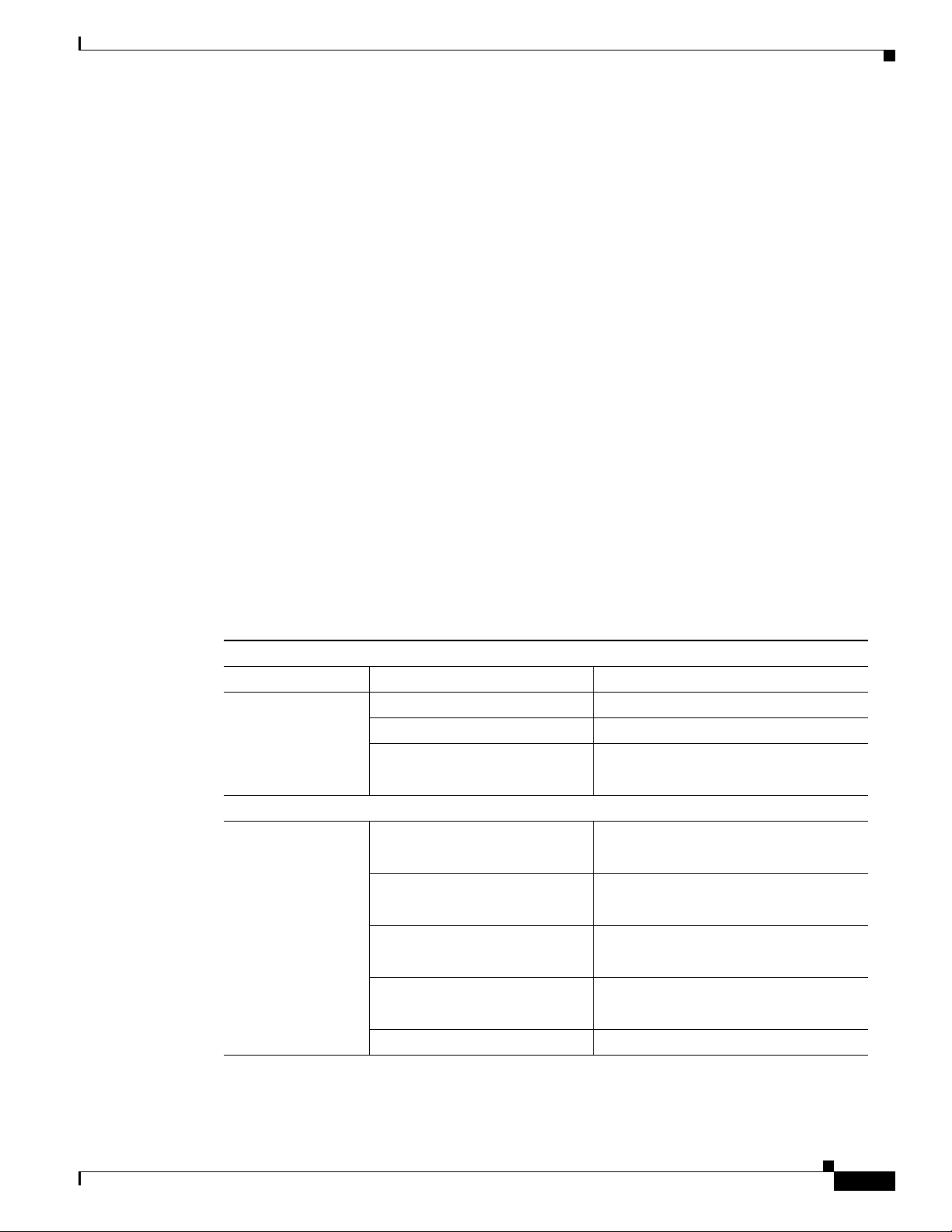
Organization
This guide is organized into the following chapters and appendix.
Chapter Name Description
Chapter 1 Chapter 1, “Product Overview” Describes the router models and the
Chapter 2 Chapter 2, “Installing the Router” Lists the items shipped with the router, the
Chapter 3 Chapter 3, “Connecting the Router” Describes typical connections for the
Chapter 4 Chapter 4, “Initial Configuration” Provides the procedures for initially
Appendix A Appendix A, “Technical Specifications” Provides the router, port, and cabling
hardware features available.
equipment and tools necessary for
installing the router, the safety warnings
and guidelines, and the procedures for
installing the router.
router, procedures for connecting the
router to various devices, and how to
verify the connections.
configuring the router settings.
specifications.
Conventions
This section describes the conventions used in this guide.
Note Means reader take note. Notes contain helpful suggestions or references to additional information and
material.
Caution This symbol means reader be careful. In this situation, you might do something that could result in
equipment damage or loss of data.
Tip Means the following information will help you solve a problem. The tip information might not be
troubleshooting or even an action, but could be useful information.
viii
Cisco Integrated Services Router Hardware Installation Guide
Page 11

Warning
Waarschuwing
Varoitus
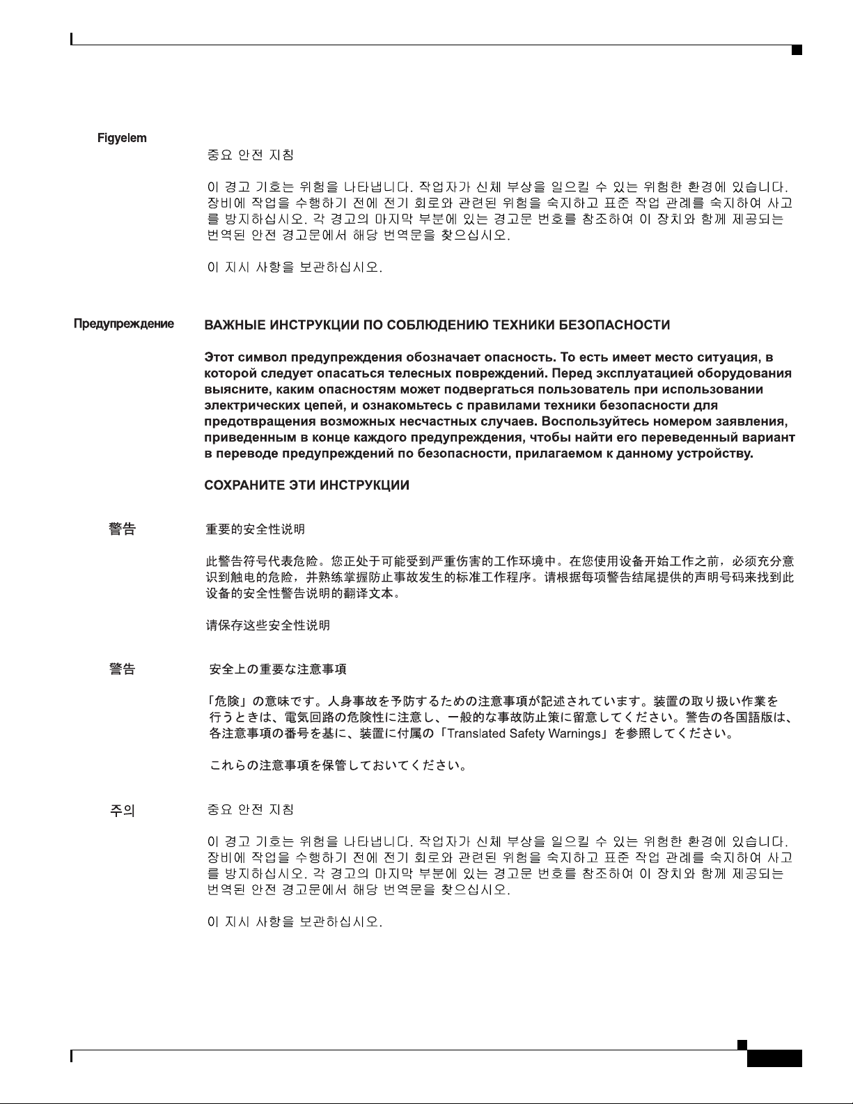
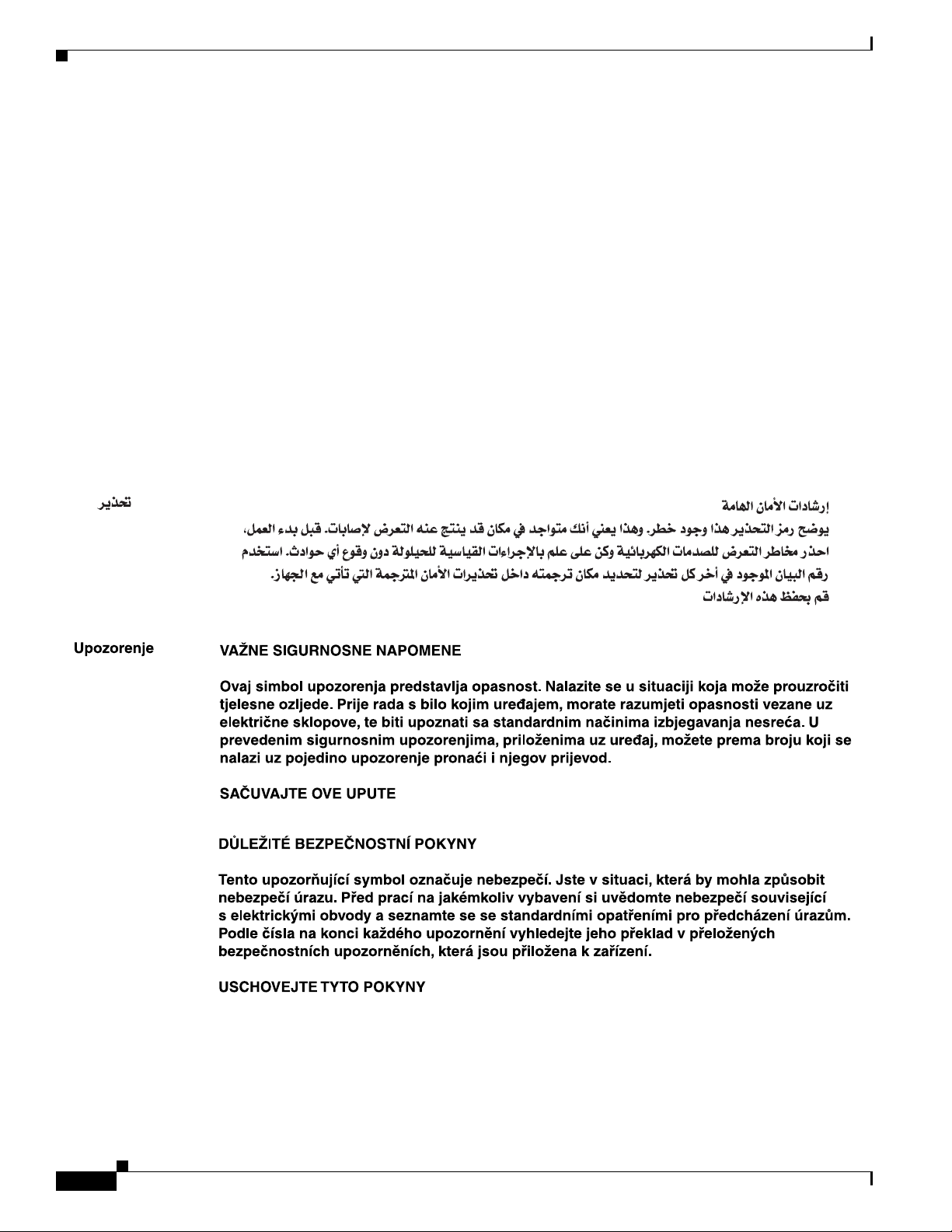
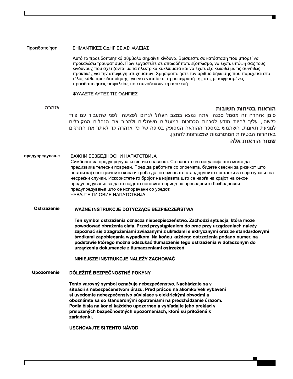
IMPORTANT SAFETY INSTRUCTIONS
This warning symbol means danger. You are in a situation that could cau se bodily inju ry. Before you
work on any equipment, be aware of the hazards involved with electrical circuitry and be familiar
with standard practices for preventing accidents. Use the statement number provided at the end of
each warning to locate its translation in the translated safety warnings that accompanied this
device.
Statement 1071
SAVE THESE INSTRUCTIONS
BELANGRIJKE VEILIGHEIDSINSTRUCTIES
Dit waarschuwingssymbool betekent gevaar. U verkeert in een situatie die lichamelijk letsel kan
veroorzaken. Voordat u aan enige apparatuur gaat werken, dient u zich bewust te zijn van de bij
elektrische schakelingen betrokken risico's en dient u op de hoogte te zijn van de standaard
praktijken om ongelukken te voorkomen. Gebruik het nummer van de verklaring onderaan de
waarschuwing als u een vertaling van de waarschuwing die bij het apparaat wordt geleverd, wilt
raadplegen.
BEWAAR DEZE INSTRUCTIES
TÄRKEITÄ TURVALLISUUSOHJEITA
Tämä varoitusmerkki merkitsee vaaraa. Tilanne voi aiheuttaa ruumiillisia vammoja. Ennen kuin
käsittelet laitteistoa, huomioi sähköpiirien käsittelemiseen liittyvät riskit ja tutustu
onnettomuuksien yleisiin ehkäisytapoihin. Turvallisuusvaroitusten käännökset löytyvät laitteen
mukana toimitettujen käännettyjen turvallisuusvaroitusten joukosta varoitusten lopussa näkyvien
lausuntonumeroiden avulla.
Attention
Warnung
SÄILYTÄ NÄMÄ OHJEET
IMPORTANTES INFORMATIONS DE SÉCURITÉ
Ce symbole d'avertissement indique un danger. Vous vous trouvez dans une situation pouvant
entraîner des blessures ou des dommages corporels. Avant de travailler sur un équipement, soyez
conscient des dangers liés aux circuits électriques et familiarisez-vous avec les procédures
couramment utilisées pour éviter les accidents. Pour prendre connaissance des traductions des
avertissements figurant dans les consignes de sécurité traduites qui accompagnent cet appareil,
référez-vous au numéro de l'instruction situé à la fin de chaque avertissement.
CONSERVEZ CES INFORMATIONS
WICHTIGE SICHERHEITSHINWEISE
Dieses Warnsymbol bedeutet Gefahr . Sie be finden sich in einer Situation, die zu V erletzungen führen
kann. Machen Sie sich vor der Arbeit mit Geräten mit den Gefahren elektrischer Schaltungen und
den üblichen Verfahren zur Vorbeugung vor Unfällen vertraut. Suchen Sie mit der am Ende jeder
Warnung angegebenen Anweisungsnummer nach der jeweiligen Übersetzung in den übersetzten
Sicherheitshinweisen, die zusammen mit diesem Gerät ausgeliefert wurden.
BEWAHREN SIE DIESE HINWEISE GUT AUF.
Cisco Integrated Services Router Hardware Installation Guide
ix
Page 12

Avvertenza
Advarsel
Aviso
IMPORTANTI ISTRUZIONI SULLA SICUREZZA
Questo simbolo di avvertenza indica un pericolo. La situazione potrebbe causare infortuni alle
persone. Prima di intervenire su qualsiasi apparecchiatura, occorre essere al corrente dei pericoli
relativi ai circuiti elettrici e conoscere le procedure standard per la prevenzione di incidenti.
Utilizzare il numero di istruzione presente alla fine di ciascuna avvertenza per individuare le
traduzioni delle avvertenze riportate in questo documento.
CONSERVARE QUESTE ISTRUZIONI
VIKTIGE SIKKERHETSINSTRUKSJONER
Dette advarselssymbolet betyr fare. Du er i en situasjon som kan føre til skade på person. Før du
begynner å arbeide med noe av utstyret, må du være oppmerksom på farene forbundet med
elektriske kretser , og kjenn e til standardprosedyrer for å forhindre u lykker. Bruk nummeret i slutten
av hver advarsel for å finne oversettelsen i de oversatte sikkerhetsadvarslene som fulgte med denne
enheten.
TA VARE PÅ DISSE INSTRUKSJONENE
INSTRUÇÕES IMPORTANTES DE SEGURANÇA
Este símbolo de aviso significa perigo. Você está em uma situação que poderá ser causadora de
lesões corporais. Antes de iniciar a utilização de qualquer equipamento, tenha conhecimento dos
perigos envolvidos no manuseio de circuitos elétricos e familiarize-se com as práticas habituais de
prevenção de acidentes. Utilize o número da instrução fornecido ao final de cada aviso para
localizar sua tradução nos avisos de segurança traduzidos que acompanham este dispositivo.
¡Advertencia!
Varning!
GUARDE ESTAS INSTRUÇÕES
INSTRUCCIONES IMPORTANTES DE SEGURIDAD
Este símbolo de aviso indica peligro. Existe riesgo para su integridad física. Antes de manipular
cualquier equipo, considere los riesgos de la corriente eléctrica y familiarícese con los
procedimientos estándar de prevención de accidentes. Al final de cada advertencia encontrará el
número que le ayudará a encontrar el texto traducido en el apartado de traducciones que acompaña
a este dispositivo.
GUARDE ESTAS INSTRUCCIONES
VIKTIGA SÄKERHETSANVISNINGAR
Denna varningssignal signalerar fara. Du befinner dig i en situation som kan leda till personskada.
Innan du utför arbete på någon utrustning måste du vara medveten om farorna med elkretsar och
känna till vanliga förfaranden för att förebygga olyckor. Använd det nummer som finns i slutet av
varje varning för att hitta dess översättning i de översatta säkerhetsvarningar som medföljer denna
anordning.
SPARA DESSA ANVISNINGAR
Cisco Integrated Services Router Hardware Installation Guide
x
Page 13
Cisco Integrated Services Router Hardware Installation Guide
xi
Page 14
Aviso
Advarsel
INSTRUÇÕES IMPORTANTES DE SEGURANÇA
Este símbolo de aviso significa perigo. Você se encontra em uma situação em que há risco de lesões
corporais. Antes de trabalhar com qualquer equipamento, esteja ciente dos riscos que envolvem os
circuitos elétricos e familiarize-se com as práticas padrão de prevenção de acidentes. Use o
número da declaração fornecido ao final de cada aviso para localizar sua tradução nos avisos de
segurança traduzidos que acompanham o dispositivo.
GUARDE ESTAS INSTRUÇÕES
VIGTIGE SIKKERHEDSANVISNINGER
Dette advarselssymbol betyder fare. Du befinder dig i en situation med risiko for
legemesbeskadigelse. Før du begynder arbejde på udstyr, skal du være opmærksom på de
involverede risici, der er ved elektriske kredsløb, og du skal sætte dig ind i standardprocedurer til
undgåelse af ulykker. Brug erklæringsnummeret efter hver advarsel for at finde oversættelsen i de
oversatte advarsler, der fulgte med denne enhed.
GEM DISSE ANVISNINGER
xii
Cisco Integrated Services Router Hardware Installation Guide
Page 15
Cisco Integrated Services Router Hardware Installation Guide
xiii
Page 16
Warning
Warning
Warning
Warning
When installing the product, please use the provided or designated connection cables/power
cables/AC adaptors. Using any other cables/adaptors could cause a malfunction or a fire. Electrical
Appliance and Material Safety Law prohibits the use of UL-certified cables (that have the “UL” shown
on the code) for any other electrical devices than products designated by CISCO. The use of cables
that are certified by Electrical Appliance and Material Safety Law (that have “PSE” shown on the
code) is not limited to CISCO-designated products.
Statement 371
Read the wall-mounting instructions carefully before beginning installation. Failure to use the
correct hardware or to follow the correct procedures could result in a hazardous situation to people
and damage to the system.
Statement 378
There is the danger of explosion if the battery is replaced incorrectly. Replace the battery only with
the same or equivalent type recommended by the manufacturer. Dispose of used batteries according
to the manufacturer’s instructions
. Statement 1015
T o avoid electric shock, do not connect safety extra-low voltage (SELV) circuits to telephone-network
voltage (TNV) circuits. LAN ports contain SELV circuits, and WAN ports contain TNV circuits. Some
LAN and WAN ports both use RJ-45 connectors. Use caution when connecting cables.
Statement 1021
xiv
Warning
This equipment must be grounded. Never defeat the ground conductor or operate the equipment in the
absence of a suitably installed ground conductor. Contact the appropriate electrical inspection
authority or an electrician if you are uncertain that suitable grounding is available
Cisco Integrated Services Router Hardware Installation Guide
. Statement 1024
Page 17

Warning
Warning
Warning
Warning
Warning
Warning
If the symbol of suitability with an overlaid cross appears above a port, you must no t connect the port
to a public network that follows the European Union standards. Connecting the port to this type of
public network can cause severe personal injury or can damage the unit.
Statement 1031
Connect the unit only to DC power source that complies with the safety extra-low voltage (SELV)
requirements in IEC 60950 based safety standards.
Statement 1033
Do not use this product near water; for example, near a bath tub, wash bowl, kitchen sink or laundry
tub, in a wet basement, or near a swimming pool.
Statement 1035
Never install telephone jacks in wet locations unless the jack is specifically designed for wet
locations.
Statement 1036
Never touch uninsulated telephone wires or terminals unless the telephone line has been
disconnected at the network interface.
Statement 1037
Avoid using a telephone (other than a cordless type) during an electrical storm. There may be a remote
risk of electric shock from lightning.
Statement 1038
Warning
Warning
Warning
Warning
Warning
When installing or replacing the unit, the ground connection must always be made first and
disconnected last.
Statement 1046
Do not locate the antenna near overhead power lines or other electric light or power circuits, or
where it can come into contact with such circuits. When installing the antenna, take extreme care
not to come into contact with such circuits, because they may cause serious injury or death. For
proper installation and grounding of the antenna, please refer to national and local codes (for
example, U.S.:NFPA 70, National Electrical Code, Article 810, Canada: Canadian Electrical Code,
Section 54).
No user-serviceable parts inside. Do not open.
Installation of the equipment must comply with local and national electrical codes.
Statement 1052
Statement 1073
Statement 1074
Only trained and qualified personnel should be allowed to install, replace, or service this equipment.
Statement 1030
Cisco Integrated Services Router Hardware Installation Guide
xv
Page 18

Warning
Warning
Warning
Warning
Warning
Read the installation instructions before connecting the system to the power source.
Ultimate disposal of this product should be handled according to all national laws and regulations.
Statement 1040
The covers are an integral part of the safety design of the product. Do not operate the unit without the
covers installed.
Hot surface.
The equipment is suitable for installation in the following locations:
Network Telecommunications Facilities
Location where the NEC applies
OSP
Statement 1077
Statement 1079
Related Documentation
Statement 1004
• Regulatory Compliance and Safety Information for Cisco 800 Series Routers
• Cisco IOS Software Releases 12.4 Special and Early Deployments
• Cisco IOS Quality of Service Solutions Command Reference, Release 12.4T
• Cisco IOS Security Configuration Guide, Release 12.4T
• Cisco IOS Security Command Reference, Release 12.4T
• Cisco CP Express User’s Guide
Searching Cisco Documents
T o search an HTML document using a web bro wser, press Ctrl-F (W indows) or Cmd-F (Apple). In most
browsers, the option to search whole words only , in voke case sensiti vity , or search forward and backward
is also available.
To search a PDF document in Adobe Reader, use the basic Find toolbar (Ctrl-F) or the Full Reader
Search window (Shift-Ctrl-F). Use the Find toolbar to f ind words or phrases within a specific document.
Use the Full Reader Search window to search multiple PDF files simultaneously and to change case
sensitivity and other options. A dobe Reader’ s online help has mor e information about ho w to search PDF
documents.
xvi
Cisco Integrated Services Router Hardware Installation Guide
Page 19

Obtaining Documentation and Submitting a Service Request
For information on obtaining documentation, submitting a service request, and gathering additional
information, see the monthly What’ s New in Cisco Product Documentation, which also lists all new and
revised Cisco technical documentation, at:
http://www.cisco.com/en/US/docs/general/whatsnew/whatsnew.html
Subscribe to the What’s New in Cisco Product Documentation as a Really Simple Syndication (RSS) feed
and set content to be delivered directly to your desktop using a reader application. The RSS feeds are a free
service and Cisco currently supports RSS Version 2.0.
Cisco Integrated Services Router Hardware Installation Guide
xvii
Page 20

xviii
Cisco Integrated Services Router Hardware Installation Guide
Page 21

Product Overview
This chapter provides an overview of the features available for the Cisco 812, Cisco 819, Cisco 860, 880,
890 Integrated Services Router (ISR) and contains the following sections:
• Cisco 810 Series, page 1-1
• Cisco 860, 880, 890 Series, page 1-42
Note For compliance and safety information, see Regulatory Compliance and Safety Information for Cisco
800 Series Routers.
Cisco 810 Series
This section contains the following:
• Cisco 812 Series, page 1-1
• Cisco 819 Series, page 1-10
CHA PTER
1
Cisco 812 Series
This section provides an overvie w of the features a vailable for the Cisco 812 Integrated Services Router
(ISR) and contains the following sections:
• General Description, page 1-1
• Hardware Features, page 1-4
• SKU Information, page 1-9
Note For compliance and safety information, see Regulatory Compliance and Safety Information for Cisco
800 Series and SOHO Series Routers.
General Description
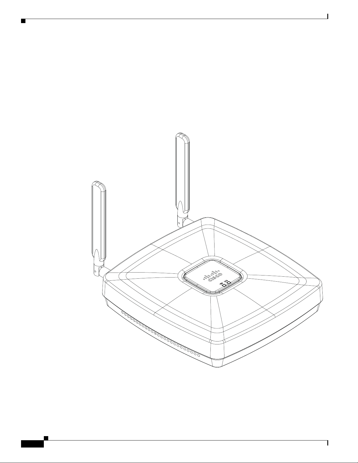
The Cisco 812 ISR is a new router that looks like an Access Point with 3G, WLAN, and routing
capabilities.
Cisco Integrated Services Router Hardware Installation Guide
1-1
Page 22
Cisco 810 Series
344399
Chapter 1 Product Overview
The 3rd Generation (3G) is a generation of standards for mobile technology that facilitates growth,
increased in bandwidth, and supports more diverse applications.
The Cisco 812 ISR can be powered by an (included) external AC adapter or by a PoE+ capable Ethernet
source using an optional Cisco PoE splitter C810-POE-SPL.
A Wireless Local Area Network (WLAN) implements a flexible data communication system frequently
augmenting rather than replacing a wired LAN within a b uilding or campus. WLANs use radio freq uency
to transmit and receive data over the air, minimizing the need for wired connections. Figure 1-1 shows
the Cisco 812 ISR.
Figure 1-1 Cisco 812 ISR
1-2
Cisco Integrated Services Router Hardware Installation Guide
Page 23
Chapter 1 Product Overview
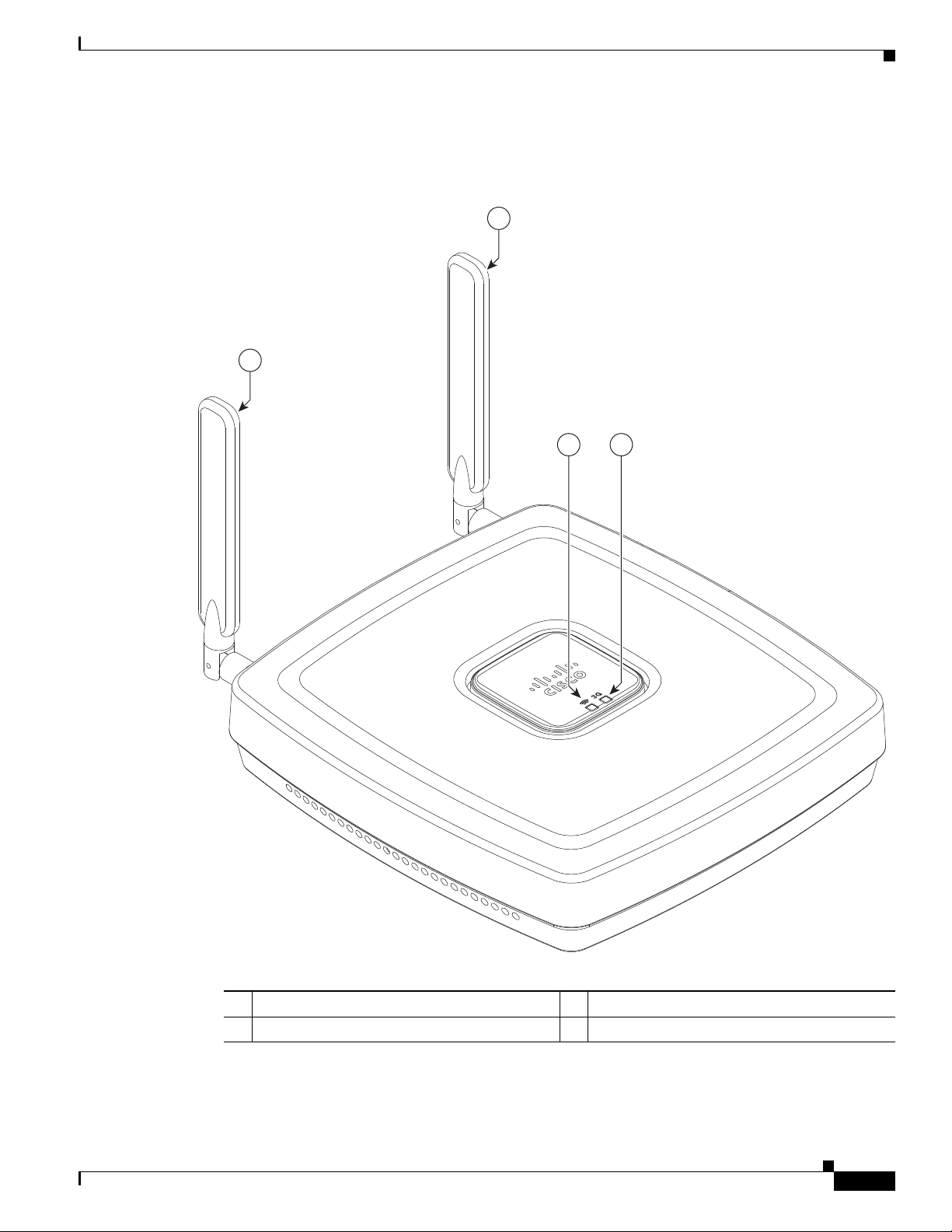
Figure 1-2 shows the 3G antenna and LEDs display.
Figure 1-2 Cisco 812 ISR 3G and LEDs Display
Cisco 810 Series
2
1
43
344400
1 3G diversity antenna 3 WiF i LED
2 3G main antenna 4 3G LED
Cisco Integrated Services Router Hardware Installation Guide
1-3
Page 24
Cisco 810 Series
MAIN
C812G
GE WAN
S L
CON/
AUX
5VDC 4.0A
DIV/GPS
3 421
Chapter 1 Product Overview
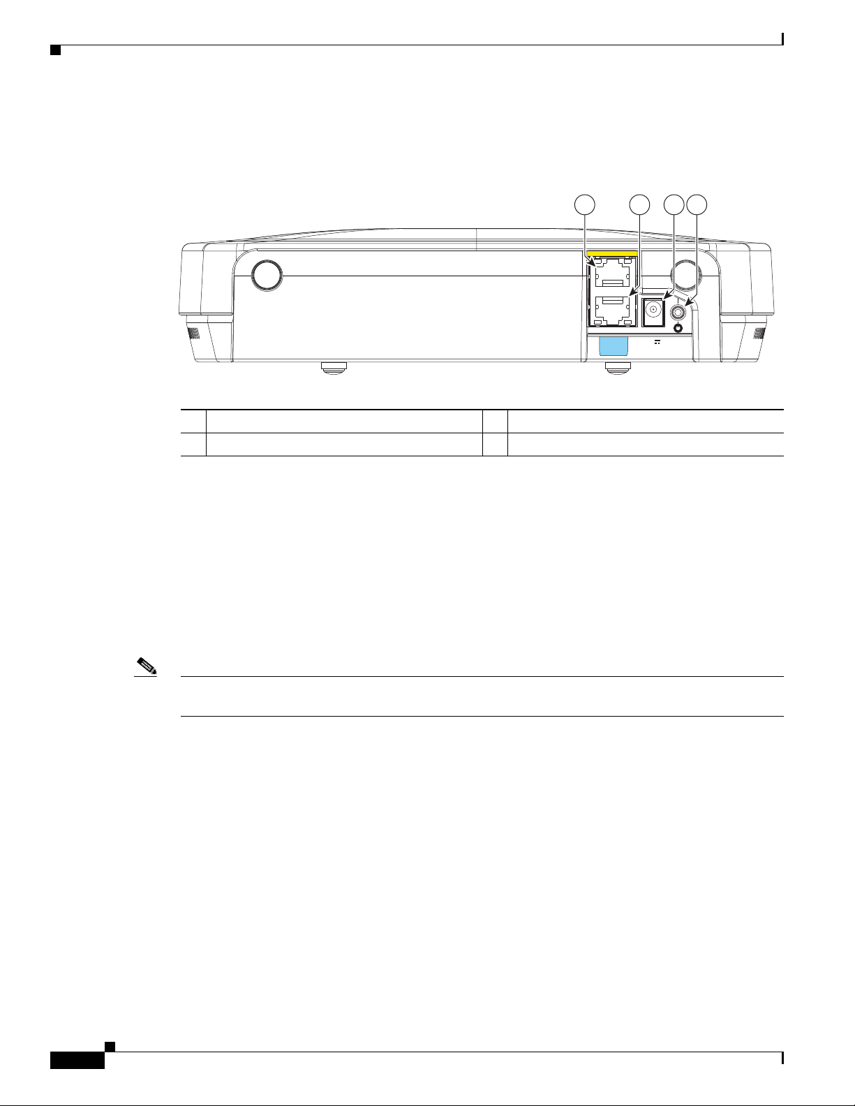
Figure 1-3 shows the I/O side of the Cisco 812 ISR.
Figure 1-3 Cisco 812 ISR I/O Side
1 GE WAN port 3 Power connection port
2 Console/Aux port 4 Power switch
Hardware Features
The Cisco 812 ISR supports the following hardware features:
Note The WAAS Express feature is not supported. This feature will be supported for 3G and 4G interfaces
with later IOS releases.
Platform Features
The Cisco 812 ISR has the following platform features:
• Platform Features, page 1-4
• Antenna, page 1-5
• LEDs, page 1-5
• Memory, page 1-8
• Power Supply, page 1-8
• 1x GE Enabled WAN (1000/100/10 Base T)
• 2 TNC connectors for 3G main and diversity antenna (diversity antenna multiplexed with GPS)
• 512 MB Compact Flash Memory
• 512 MB DRAM
• AC Power Brick (100–264 V and max 0.5 A)
• Optional PoE+ (802.3at Class 4) Power Splitter
• Built-in Grounding
1-4
Cisco Integrated Services Router Hardware Installation Guide
Page 25
Chapter 1 Product Overview
Antenna
LEDs
Cisco 810 Series
• Ceiling and Wall Mounting Option
• LED indicators for the platform
The Cisco 812 ISR supports 3G external antenna and WiFi embedded antenna.
3G External Antenna
The Cisco 812 ISR provides two standard p anel-mount TNC connectors to support 3G. Th e main antenna
is used for the primary 3G antenna. The second can be used as a diversity recei v e only 3G antenna or an
amplified GPS antenna. See Figure 1-2 for the location of the antennas.
WiFi Embedded Antenna
The Cisco 812 ISR supports Dual ports WiFi radios (802.11 a/b/g/n) with embedded 2x3 MIMO.
For compliance and safety information, see the Regulatory Compliance and Safety Information for the
Cisco 800 Series and SOHO Series Routers.
The Cisco 812 ISR has two LEDs located on the top side of the router. The 3G LED is located on the
lower right side with respect to the Cisco logo. 3G LED supports multip le functions and colors. The W iFi
LED is located on lower left sid e with respect to the Cisco logo. Table 1-1 describes the 3G LED for the
Cisco 812 ISR.
Table 1-1 Cisco 812 3G LED Descriptions
ROMMON Mode
3G LED LED Color Description
System Yellow FPGA download is complete.
Green (four blinks) ROMMON is running.
Off No power.
Incomplete FPGA download.
IOS 3G Mode
3G Service Type White MC8700—2G (GPRS/EDGE)
MC5728—1xRTT
Green MC8700—3G (UMTS)
MC5728—EVDO Rev 0
Light Blue MC8700—3.5G (HSPA)
MC5728—EVDO Rev A
Blue MC8700—3.7G (HSPA+)
MC5728—N/A
Off (solid) No service.
Cisco Integrated Services Router Hardware Installation Guide
1-5
Page 26

Cisco 810 Series
Chapter 1 Product Overview
Table 1-1 Cisco 812 3G LED Descriptions (continued)
ROMMON Mode
3G LED LED Color Description
1
RSSI
Fault / Alarm Amber (solid) Fault detected.
1. The LED colors of RSSI can be any of the four colors (White, Green, Light Blue, or Blue) listed under 3G service type.
White, Green, Light Blue, or
Blue (solid)
White, Green, Light Blue, or
Blue (three blinks and then a
long pause)
White, Green, Light Blue, or
Blue (two blinks and then a long
pause)
White, Green, Light Blue, or
Blue (one blink and then a long
pause)
Signal > –60 dBm
Very strong signal
Signal <= –60 to 74 dBm
Strong signal.
Signal <= –75 to –89 dBm
Fair signal.
Signal <= –90 to –109 dBm
Marginal signal.
Off Signal <= –110 dBm
Unusable signal.
Red (four blinks) Temperature alert.
Red (solid) Software failure.
Power cycle.
1-6
Cisco Integrated Services Router Hardware Installation Guide
Page 27
Chapter 1 Product Overview
Table 1-2 describes the WiFi LED for the Cisco 812 ISR.
Table 1-2 Cisco 812 ISR WiFi LED Descriptions
Message Type Color Description
Boot loader status sequence Blinking Green DRAM memory test in progress.
Association status Green Normal operating condition with no
Operating status Blinking Blue Software upgrade in progress.
Boot loader warnings Blinking Blue Configuration recovery in progress.
Cisco 810 Series
DRAM memory test is OK.
Board initialization in progress.
Initializing FLASH file system.
Initializing Ethernet.
Ethernet is OK.
Starting Cisco IOS.
Initialization successful.
wireless client associated.
Blue Normal operating condition with at least
one wireless client associated.
Rapidly cycling through
Blue, Green, Red, and
White
Blinking Red Ethernet link not operational.
Yellow Router is powered up.
Blinking Green LED blinks four times when ROMMON is
Access point location command invoked.
FPGA download is complete.
up.
(MODE button pushed for 2 to 3 seconds)
Red Ethernet failure.
Blinking Green Image recovery in progress (MODE button
released).
Boot loader errors Red DRAM memory test failure.
Blinking Red and Blue FLASH file system failure.
Blinking Red and Off Environment variable failure.
Bad MAC address.
Ethernet failure during image recovery.
Boot environment failure.
No Cisco image file.
Boot failure.
Cisco Integrated Services Router Hardware Installation Guide
1-7
Page 28

Cisco 810 Series
Memory
Chapter 1 Product Overview
Table 1-2 Cisco 812 ISR WiFi LED Descriptions (continued)
Message Type Color Description
Cisco IOS errors Red Software failure. Try to disconnect and
reconnect the unit power.
Cycling through Blue,
Green, Red, and Off
The Cisco 812 ISR supports 512 MB DRAM and 512 MB compact flash memory. The Host router
software runs on the first core. The second core runs the WLAN Access Point software.
If WLAN is not supported in an SKU, all 512 MB DRAM memory is allocated to the first core. For the
SKUs that support WLAN, 128 MB out of the 512 MB main memory is allocated to the second core.
If WLAN is not supported in an SKU, all 512 MB DRAM compact flash memory is allocated to the first
core. For the SKUs that support WLAN, 64 MB out of the 512 MB main memory is allocated to the
second core.
General warning.
Power Supply
The following are power adapters supported in the Cisco 812 ISR:
• AC Power Adapter, page 1-8
• PoE+ Splitter, page 1-8
AC Power Adapter
The default configuration is AC adapter that supports up to 4 A of 5 VDC current. The supported AC
power adapter is PWR2-20W-AC that has a nominal input voltage of 100 to 240 VAC.
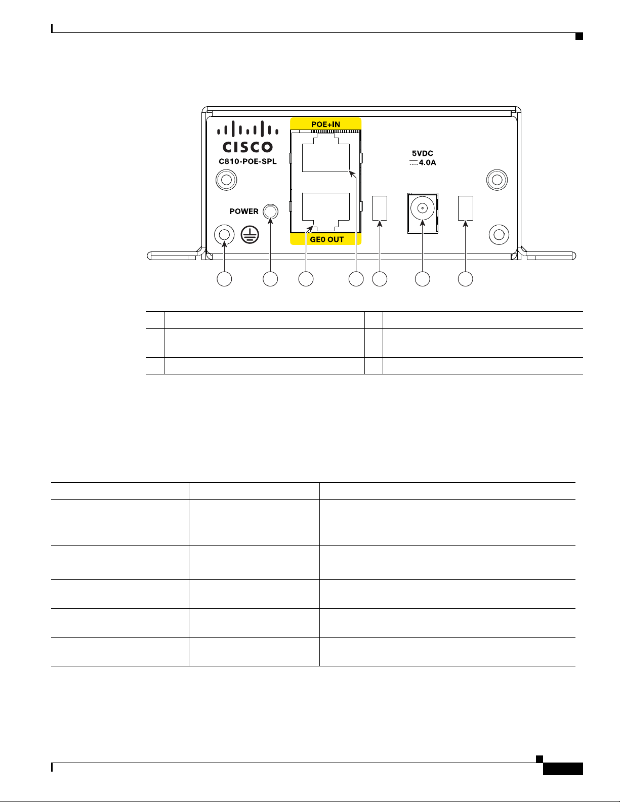
PoE+ Splitter
The Cisco PoE+ splitter (C810-POE-SPL) splits PoE+ into power and GE. It has connectors built into
the power supply at both input and output so cables can be used at desired length as an option. Figure 1-4
shows the I/O side of the PoE+ splitter.
1-8
Cisco Integrated Services Router Hardware Installation Guide
Page 29
Chapter 1 Product Overview
OUTPUT
OUTPUT
65 521
3 4
345067
Figure 1-4 PoE+ Splitter I/O Side
1 Grounding location 4 PoE+ input
2 Power status LED 5 Openings for power cord latch to lock into
3 GE0 output 6 Input power connection
Cisco 810 Series
enclosure
SKU Information
Table 1-3 lists the different SKUs available fo r the Cisco 812 ISR. The AP802-A GN-X-K9 (WLAN PID)
is integrated as part of the router for the SKUs that support WLAN and is not orderable separately.
Table 1-3 Supported SKUs
SKU ID WLAN PID Description
C812G+7-K9 — C812 Secure Router Standalone Unit (non-US) 3.7G HSPA
+ Release 7 with SMS/GPS
WLAN is not supported.
C812G-CIFI+7-E-K9 AP802-AGN-E-K9 C812 Secure Router (non-US) 3.7G HSPA + Release 7 with
SMS/GPS and Dual WiFi Radio with ETSI
C812G-CIFI+7-N-K9 AP802-AGN-N-K9 C812 Secure Router (non-US) 3.7G HSP A + Release 7 with
SMS/GPS and Dual WiFi Radio with ANZ
C812G-CIFI-V-A-K9 AP802-AGN-A-K9 C812 Secure Router for Verizon EV-DO Rev A with
SMS/GPS and Dual WiFi Radio with FCC
C812G-CIFI-S-A-K9 AP802-AGN-A-K9 C812 Secure Router for Sprint EV-DO Rev A with
SMS/GPS and Dual WiFi Radio with FCC
Cisco Integrated Services Router Hardware Installation Guide
1-9
Page 30

Cisco 810 Series
Cisco 819 Series
This section provides an overview of the features available for the Cisco 819 and Cisco 819H Inte grated
Services Routers (ISRs) and contains the following sections:
• General Description, page 1-10
• SKU Information, page 1-14
• Hardware Features, page 1-27
Note Cisco 819 is used to refer to Cisco 819HG, Cisco 819G, Cisco 819H, Cisco 819GW, Cisco 819HGW,
Cisco 819HWD, Cisco 819HG-4G, and Cisco 819G-4G ISRs unless specifically called out otherwise.
Note This product is a Class 1 Outside Plant (OSP) as per Telcordia GR-3108.
Note For compliance and safety information, see Regulatory Compliance and Safety Information Roadmap
that ships with the router and Regulatory Compliance and Safety Information for Cisco 800 Series and
SOHO Series Routers.
Chapter 1 Product Overview
General Description
The Cisco 819 Integrated Services Router, part of the Cisco Integrated Services Routers Generation 2
(ISR G2) Family designed in compact hardened and non-hardened form factors, is the smallest Cisco
IOS Software router with support for integrated fourth-generation (4G LTE) and third-generation (3G)
wireless WAN (mobile broadband backhaul). The Cisco 819GW now supports Dual 802.11 a/b/g/n
radios WiFi. The Cisco 819 ISR machine-to-machine gateway provides a rapidly deployable, highly
available, reliable, and secure solution into machine-to-machine applications for financial, telemetry,
utility, retail, industrial automation, and transportation with comprehensive management capability.
Transparently integrated into Cisco IOS Softw are as an enterprise-class feature, the Cisco 819 Hardened
ISR provides highly secure data, voice, and video communications to stationary and mobile network
nodes across wired and wireless links.
Available in both non-hardened (Cisco 819G) and hardened (Cisco 819HG) versions, the Cisco 819
supporting 4G LTE and 3G wireless WAN (WWAN) speeds offers a cost-effective, rapidly deployable,
reliable, and secure primary or backup solution. With support for industrial-grade components, the
hardened Cisco 819HG extends the ISR machine-to-machine gateway footprint and provides the
flexibility for deployment in many different stationary and mobile environments where space, heat
dissipation, exposure to extreme temperatures, harsher environments, and low power consumption are
critical factors. For mobile applications, Mobile IP deli vers transparent roaming across multipl e wireless
networks capable of covering wide geographic areas.
The Cisco 819 ISR is a standard form factor with a commercial operating range. The 3G Cisco 819 ISRs
support the 3G speeds (High-Speed PacketAccess Plus [HSP A+] enabling up to 4G speeds and Evolut ion
Data Optimized [EVDO Rev A]). They are backward-compatible with High-Speed Packet Access
(HSPA), Universal Mobile Telecommunications Service (UMTS), Enhanced Data Rates for Globa l
Evolution (EDGE), General Packet Radio Service (GPRS), and EVDO Rev 0/1xRTT.
1-10
Cisco Integrated Services Router Hardware Installation Guide
Page 31

Chapter 1 Product Overview
The 4G LTE C819 supports the latest Third-Generation Partnership Project (3GPP) Release 8 LTE
standards. The Cisco 4G multimode L TE WWAN C819 provides persistent and reliable L TE connecti vity
with fallback and transparent handof f to earlier tech nologies. The Cisco 819HG-4G and Cisco 819G- 4G
support multimode 4G LTE and have embedded Sierra Wireless multimode modem.
The Cisco 819 ISR is a desktop form factor with built-i n wall-mou nt features, floor mount , and DIN rail
mount features in selected SKUs. These routers are powered by an external AC power or optional DC
adapter. Figure 1-5 shows the Cisco 819HG ISR.
The Cisco 819GW ISRs support WiFi radios with a higher memory density and a new barrel-type power
connector. A Wireless Local Area Network (WLAN) implements a flexible data communication system
frequently augmenting rather than replacing a wired LAN within a building or campus. WLANs use
radio frequency to transmit and receive data over the air, minimizing the need for wired connections.
Figure 1-6 shows the Cisco 819HGW ISR.
The Cisco 819GW ISRs have the following additional features:
• Dual 802.11 a/b/g/n radios
• External WiFi antenna
• WLAN LED
Cisco 810 Series
Figure 1-5 Cisco 819HG Integrated Services Router
283010
Cisco Integrated Services Router Hardware Installation Guide
1-11
Page 32

Cisco 810 Series
285479
245547
1 43 6 7 9 10 11 12
5 8
2
Chapter 1 Product Overview
Figure 1-6 Cisco 819HGW Integrated Services Router
Figure 1-7 shows the front panel details of the Cisco 819HG ISR.
Figure 1-7 Cisco 819HG ISR Front Panel
1 3G main antenna 7 FE ports
2 LEDs 8 GE WAN port
3 Reset button 9 Console/Aux port
Cisco Integrated Services Router Hardware Installation Guide
1-12
Page 33

Chapter 1 Product Overview
344077
21 43 6 7 9 10 11 12
5 8
4 3G mini-USB diagnostic port 10 5 VDC molex power input
5 Diversity/GPS antenna 11 Power switch
6 12-in-1 serial port 12 Ground
Figure 1-8 shows the front panel details of the Cisco 819HGW ISR.
Figure 1-8 Cisco 819HGW ISR Front Panel
Cisco 810 Series
1 3G main antenna 7 FE ports
2 LEDs 8 GE WAN port
3 Reset button 9 Console/Aux port
4 3G mini-USB diagnostic port 10 5 VDC barrel-type power input
5 Diversity/GPS antenna 11 Power switch
6 12-in-1 serial port 12 Ground
Cisco Integrated Services Router Hardware Installation Guide
1-13
Page 34

Cisco 810 Series
285447
1 43 6 7 9 10 11 13
5 128
2
Chapter 1 Product Overview
Figure 1-9 shows the front panel details of the Cisco 819 4G LTE ISR.
Figure 1-9 Cisco 819 4G LTE ISR Front Panel
1 4G antenna connector—M0/MAIN 8 GE WAN port
2 LEDs 9 Console/Aux port
3 Reset button 10 Power input
4 4G/3G port 11 Power switch
5 4G antenna connector—M1/DIV 12 Active GPS antenna connector
6 Serial port 13 Ground
7 FE ports
SKU Information
Note WLAN is not supported.
Table 1-4 lists the different 3G SKUs available for the Cisco 819HG and Cisco 819G ISRs. All SKUs
support external antenna.
Table 1-4 Supported 3G SKUs for Cisco 819HG and Cisco 819G ISRs
SKU ID Description
C819HG+7-K9 Compact Hardened 3G IOS Router with Global HSPA + Release 7 based on
MC8705
C819HG-U-K9 Compact Hardened 3G IOS Router with GLOB AL HSPA Release 6 based on
MC8795V
C819HG-V-K9 Compact Hardened 3G IOS Router with Verizon EVDO Rev A based on
MC5728V
C819HG-S-K9 Compact Hardened 3G IOS Router with Sprint EVDO Rev A based on
MC5728V
Cisco Integrated Services Router Hardware Installation Guide
1-14
Page 35

Chapter 1 Product Overview
Table 1-4 Supported 3G SKUs for Cisco 819HG and Cisco 819G ISRs (continued)
SKU ID Description
C819HG-B-K9 Compact Hardened 3G IOS Router with Bharat generic EVDO Re v A based
C819G+7-K9 Compact Non-hardened 3G IOS Router with Global HSP A + Release 7 based
C819G-U-K9 Compact Non-hardened 3G IOS Router with GLOBAL HSPA Release 6
C819G-V-K9 Compact Non-hardened 3G IOS Router with Verizon EVDO Rev A based on
C819G-S-K9 Compact Non-hardened 3G IOS Router with Sprint EVDO Rev A based on
C819G-B-K9 Compact Non-hardened 3G IOS Router with Bharat generic EVDO Rev A
Cisco 810 Series
on MC5728V
on MC8705
based on MC8795V
MC5728V
MC5728V
based on MC5728V
Cisco Integrated Services Router Hardware Installation Guide
1-15
Page 36

Chapter 1 Product Overview
Cisco 810 Series
Table 1-5 lists the different SKUs available for the Cisco 819HGW, Cisco 819H, and Cisco 819HWD
ISRs.
Table 1-5 Supported SKUs for Cisco 819HGW, Cisco 819H, and Cisco 819HWD ISRs
WiFi External Antenna
SKU ID WLAN ID
C819HGW+7-E-K9 AP802H-AGN-E-K9 Yes Cisco 819 Secure Hardened M2M
C819HGW+7-N-K9 AP802H-AGN-N-K9 Yes Cisco 819 Secure Hardened M2M
C819HGW+7-A-A-K9 AP802H-AGN-A-K9 Yes Cisco 819 Secure Hardened M2M
C819HGW-V-A-K9 AP802H-AGN-A-K9 Yes Cisco 819 Secure Hardened Router
C819HGW-S-A-K9 AP802H-AGN-A-K9 Yes Cisco 819 Secure Hardened Router
C819H-K9 — — Cisco 819 Secure Hardened Router
C819HWD-E-K9 AP802H-AGN-E-K9 Yes Cisco 819 Secure Hardened Router
Support Description
GW (non-US) 3.7G HSPA + Release
7 with SMS/GPS and Dual WiFi
Radio with ETSI
GW (non-US) 3.7G HSPA + Release
7 with SMS/GPS and Dual WiFi
Radio with ANZ
GW (North America) 3.7G HSPA +
Release 7 with SMS/GPS and Dual
WiFi Radio with FCC for ATT
for Verizon EV-DO Rev A with
SMS/GPS and Dual WiFi Radio with
FCC
for Sprint EV-DO Rev A with
SMS/GPS and Dual WiFi Radio with
FCC
with Serial
WLAN and 3G are not supported
and Dual WiFi Radio with ETSI
3G is not supported
C819HWD-A-K9 AP802H-AGN-A-K9 Yes Cisco 819 Secure Hardened Router
and Dual WiFi Radio with FCC
3G is not supported
Cisco Integrated Services Router Hardware Installation Guide
1-16
Page 37

Chapter 1 Product Overview
Table 1-6 lists the different 4G LTE SKUs available for the Cisco 819HG and Cisco 819G ISRs.
Table 1-6 Supported 4G LTE SKUs for Cisco 819HG-4G and Cisco 819G-4G ISRs
SKU ID Mode Operating Regions Frequency Band Description
C819HG-4G-V-K9 LTE—DOrA North America 700 MHz (band 13) or LTE
800/1900 MHz for CDMA
1xRTT, 1xEVDO Rev A
C819G-4G-V-K9 LTE—DOrA North America 700 MHz (band 13) for LTE
800/1900 MHz for CDMA
1xRTT, 1xEVDO Rev A
C819HG-4G-A-K9 LTE—HSPA+/
HSPA/UMTS/
EDGE/GPRS
North America 700 MHz (band 17)/AWS (band
4)/2100MHz (band 1) for LTE
800/850/1900/2100 MHz for
UMTS/ HSPA+/HSPA
850/900/1800/1900 MHz for
GSM/EDGE/GPRS
C819G-4G-A-K9 LTE—HSPA+/
HSPA/UMTS/
EDGE/GPRS
North America 700 MH z(band 17)/AWS(band
4)/2100MHz(band 1) for LTE
800/850/1900/2100 MHz for
UMTS/ HSPA+/HSPA
850/900/1800/1900 MHz for
GSM/EDGE/GPRS
C819HG-4G-G-K9 LTE—HSPA+/
HSPA/UMTS/
EDGE/GPRS
Global 800 MHz (band 20)/900 MHz
(band 8)/1800 MHz (band
3)/2100 MHz (band 1)/2600
MHz (band 7) for LTE
900/2100 MHz for UMTS/
HSPA+/HSPA
900/1800/1900 MHz for
GSM/EDGE/GPRS
Compact Hardened Cisco
819 router with multi
mode LTE feature
dedicated to Verizon
Wireless networks. This
comes with a Sierra
Wireless MC7750
modem.
Compact Non-hardened
Cisco 819 router with
multi mode LTE feature
dedicated to Verizon
Wireless networks. This
comes with a Sierra
Wireless MC7750
modem.
Compact Hardened Cisco
819 router with multi
mode LTE feature
dedicated to AT&T
Wireless networks. This
comes with a Sierra
Wireless MC7700
modem.
Compact Non-hardened
Cisco 819 router with
multi mode LTE feature
dedicated to AT&T
Wireless networks. This
comes with a Sierra
Wireless MC7700
modem.
Hardened Cisco 819
router with multi-mode
LTE feature for global
wireless networks. This
comes with a Sierra
Wireless MC7710
modem.
Cisco 810 Series
Cisco Integrated Services Router Hardware Installation Guide
1-17
Page 38

Chapter 1 Product Overview
Cisco 810 Series
Table 1-6 Supported 4G LTE SKUs for Cisco 819HG-4G and Cisco 819G-4G ISRs (continued)
SKU ID Mode Operating Regions Frequency Band Description
C819G-4G-GA-K9 LTE—HSPA+/
HSPA/UMTS/
EDGE/GPRS
C819G-4G-NA-K9
• LTE
• HSPA+
• HSPA
• UMTS
• EDGE
• GPRS
Global (Europe,
Australia and New
Zealand)
North America
(AT&T,
Bell-Canada,
Roger, Telus, and
other GSM/LTE
operators in USA
and Canada)
LTE—800 MHz (band 20)/900
MHz (band 8)/1800 MHz (band
3)/2100 MHz (band 1)/2600
MHz (band 7)
3G—800 MHz (band 6)/850
MHz (band 5)/900 MHz (band 8)
/1900 MHz (band 2) 2100 MHz
(band 1) for UMTS/
HSPA+/HSPA
2G—850/900/1800/1900 MHz
for GSM/EDGE/GPRS
LTE:
• AWS (band 4)
• 700 MHz (band 5)
• 850 MHz (band 17)
• 1900 MHz (band 2)
• 2600 MHz (band 7)
UMTS, HSPA+, HSPA:
• 1900 MHz (band 2)
Non-hardened Cisco 819
router with multi-mode
LTE feature for global
wireless networks. This
comes with a Sierra
Wireless MC7304
modem.
Non-hardened Cisco 819
router with multi-mode
LTE feature for AT & T
wireless networks. This
comes with a Sierra
Wireless MC7354 modem
• AWS (band 4)
• 850 (band 5)
GSM, EDGE, GPRS:
• 850 MHz
• 900 MHz
• 1800 MHz
• 1900 MHz
1-18
Cisco Integrated Services Router Hardware Installation Guide
Page 39

Chapter 1 Product Overview
Table 1-6 Supported 4G LTE SKUs for Cisco 819HG-4G and Cisco 819G-4G ISRs (continued)
SKU ID Mode Operating Regions Frequency Band Description
C819G-4G-ST-K9 • LTE
• EVDO Rev-A
• 1xRTT
C819G-4G-VZ-K9
• LTE
• EVDO Rev-A
• 1xRTT
North America
(Sprint)
North America
(Verizon)
LTE:
• AWS (band 4)
• 700 MHz (band 13)
• PCS 1900 MHz (band 25)
3G:
• 800 MHz (band class 0)
• 1900 MHz (band class 1)
• 800 MHz (band class 10)
2G:
• 800 MHz (band class 0)
• 1900 MHz (band class 1)
• 800 MHz (band class 10)
LTE:
• AWS (band 4)
• 700 MHz (band 13)
• PCS 1900 MHz (band 25)
3G:
• 800 MHz (band class 0)
• 1900 MHz (band class 1)
• 800 MHz (band class 10)
Non-hardened Cisco 819
router with multi-mode
LTE feature for Sprint
wireless networks. This
comes with a Sierra
Wireless MC7350
modem.
Non-hardened Cisco 819
router with multi-mode
LTE feature for Verizon
wireless networks. This
comes with a Sierra
Wireless MC7350
modem.
Cisco 810 Series
2G:
• 800 MHz (band class 0)
• 1900 MHz (band class 1)
• 800 MHz (band class 10)
Cisco Integrated Services Router Hardware Installation Guide
1-19
Page 40

Chapter 1 Product Overview
Cisco 810 Series
Table 1-6 Supported 4G LTE SKUs for Cisco 819HG-4G and Cisco 819G-4G ISRs (continued)
SKU ID Mode Operating Regions Frequency Band Description
C819GW-LTE-MN
A-AK9
• LTE
• HSPA+
• EVDO
Revision A
(DOrA)
• CDMA
• EDGE/GPRS/G
SM
North America For LTE:
• 700 MHz (Band 13)
• 700 MHz (Band 17)
• 800 MHz (Band 5)
• 1900 MHz (Band 2)
• 1900 MHz (Band 25)
• AWS 1700/2100 MHz
(Band 4)
For HS PA+:
• 850 MHz (Band 5)
• 900 MHz (Band 8)
• 1900 MHz (Band 2)
• 2100 MHz (Band 1)
• AWS 1700/2100 MHz
(Band 4)
For CDMA and EVDO Revision
A:
• 800 MHz (Band Class 0)
• 1900 MHz (Band Class 1)
• 800 MHz (Band Class 10)
For EDGE/GPRS/GSM:
• 850 MHz
• 900 MHz
• 1800 MHz
• 1900 MHz
C819GW-LTE-MNA-AK
9 is a dedicated
Multimode LTE SKU for
North American wireless
networks and comes with
a Sierra Wireless
MC7354MNA modem.
C819GW-LTE-MNA-AK
9 is a non-hardened Cisco
819 Series Router.
For 3GPP compliance, the
extended temperature
range for this SKU is -15
to 50C. For non-3GPP
compliance, it is -15 to
55C.
Dual SIMs in this SKU
provide high reliability
and cellular multihoming
support for LTE and
HSPA-based networks
using the common FW
technology within the
same region. Dual SIMs
in the North American
SKUs provide switchove r
with different FW
technology.
Note This is a 4G+
WiFi SKU. This
SKU supports all
North American
carriers like
Verizon, ATT,
Sprint, and
Canada using
MC7354MNA
modems.
1-20
Cisco Integrated Services Router Hardware Installation Guide
Page 41

Chapter 1 Product Overview
Table 1-6 Supported 4G LTE SKUs for Cisco 819HG-4G and Cisco 819G-4G ISRs (continued)
SKU ID Mode Operating Regions Frequency Band Description
C819G-LTE-MNAK9
• LTE
• HSPA+
• EDGE/GPRS/G
SM
• CDMA
• EVDO
North America LTE:
• 850MHz(band 19)
• 1500MHz(band 21)
• 2100MHz(band 1)
3G(UMTS,HSPA+,HSPA):
• 800MHz(band 6)
• 850MHz(band 5)
• 850MHz(band 19)
• 2100MHz(band 1)
2G(GSM,EDGE,GPRS):
• 850MHz
• 900MHz
• 1800MHz
• 1900MHz
C819G-LTE-MNA-K9 is
a dedicated Multimode
LTE SKU for global
wireless network and
comes with a Sierra
Wireless MC7354-MNA
modem.
C819G-LTE-MNA-K9 is
a non-hardened Cisco 819
Series Router.
For 3GPP compliance, the
extended temperature
range for this SKU is -15
to 50C. For non-3GPP
compliance, it is -15 to
55C.
Dual SIMs in this SKU
provide high reliability
and cellular multihoming
support for LTE and
HSPA-based networks
using the common FW
technology within the
same region. Dual SIMs
provide switchover with
different FW technology.
Cisco 810 Series
Note This SKU does
not have a WiFi
module.
Cisco Integrated Services Router Hardware Installation Guide
1-21
Page 42

Chapter 1 Product Overview
Cisco 810 Series
Table 1-6 Supported 4G LTE SKUs for Cisco 819HG-4G and Cisco 819G-4G ISRs (continued)
SKU ID Mode Operating Regions Frequency Band Description
C819HG-LTE-MNA
-K9
• LTE
• HSPA+
• EDGE/GPRS/G
SM
• CDMA
• EVDO
North America LTE:
• AWS (band 4)
• 850MHz(band 19)
• 1500MHz(band 21)
• 2100MHz(band 1)
3G(UMTS,HSPA+,HSPA):
• 800MHz(band 6)
• 850MHz(band 5)
• 850MHz(band 19)
• 2100MHz(band 1)
2G(GSM,EDGE,GPRS):
• 850MHz
• 900MHz
• 1800MHz
• 1900MHz
C819HG-LTE-MNA-K9
is a dedicated Multimode
LTE SKU for North
American wireless
networks and comes with
a Sierra Wireless
MC7354-MNA modem.
C819G-LTE-MNA-K9 is
a hardened Cisco 819
Series Router.
For 3GPP compliance, the
extended temperature
range for this SKU is -15
to 50C. For non-3GPP
compliance, it is -15 to
55C.
Dual SIMs in this SKU
provide high reliability
and cellular multihoming
support for LTE and
HSPA-based networks
using the common FW
technology within the
same region. Dual SIMs
provide switchover with
different FW technology.
Note This SKU does
not have a WiFi
module.
1-22
Cisco Integrated Services Router Hardware Installation Guide
Page 43

Chapter 1 Product Overview
Table 1-6 Supported 4G LTE SKUs for Cisco 819HG-4G and Cisco 819G-4G ISRs (continued)
SKU ID Mode Operating Regions Frequency Band Description
C819G-LTE-LA-K9 • LTE
• HSPA+
• HSPA
• UMTS
Latin
America/APAC
For FDD LTE:
• 700 MHz (band 28)
• 850 MHz (band 5)
• 800 MHz (band 19)
• 800 MHz (band 18)
• 900 MHz (band 8)
• 1800 MHz (band 3)
• 2100 MHz (band 1)
• 2600 MHz (band 7)
For TDD LTE:
• 1900 MHz (Band 39)
• 2300 MHz (Band 40)
• 2500 MHz (Band 41)
C819G-LTE-LA-K9 is a
dedicated Multimode L TE
SKU for Latin American
wireless networks and
comes with a Sierra
Wireless MC7430
modem.
Cisco 810 Series
• 2600 MHz (Band 38)
For UMTS, HSPA+, HSPA:
• 800 MHz (band 6)
• 800 MHz (band 19)
• 850 MHz (band 5)
• 900 MHz (band 8)
• 1700 MHz (band 9)
• 2100 MHz (band 1)
Cisco Integrated Services Router Hardware Installation Guide
1-23
Page 44

Chapter 1 Product Overview
Cisco 810 Series
Table 1-6 Supported 4G LTE SKUs for Cisco 819HG-4G and Cisco 819G-4G ISRs (continued)
SKU ID Mode Operating Regions Frequency Band Description
C819GW-LTE-LACK9
• LTE
• HSPA+
• HSPA
• UMTS
Latin
America/APAC
For FDD LTE:
• 700 MHz (band 28)
• 850 MHz (band 5)
• 800 MHz (band 19)
• 800 MHz (band 18)
• 900 MHz (band 8)
• 1800 MHz (band 3)
• 2100 MHz (band 1)
• 2600 MHz (band 7)
For TDD LTE:
• 1900 MHz (Band 39)
• 2300 MHz (Band 40)
• 2500 MHz (Band 41)
C819G-L TE-LA-CK9 is a
dedicated Multimode L TE
SKU for Latin American/
APAC wireless networks
and comes with a Sierra
Wireless MC7430
modem.
C819GW-LTE-LA-CK9
comes with WiFi-C
802.11n dual radio.
• 2600 MHz (Band 38)
For UMTS, HSPA+, HSPA:
• 800 MHz (band 6)
• 800 MHz (band 19)
• 850 MHz (band 5)
• 900 MHz (band 8)
• 1700 MHz (band 9)
• 2100 MHz (band 1)
1-24
Cisco Integrated Services Router Hardware Installation Guide
Page 45

Chapter 1 Product Overview
Table 1-6 Supported 4G LTE SKUs for Cisco 819HG-4G and Cisco 819G-4G ISRs (continued)
SKU ID Mode Operating Regions Frequency Band Description
C819GW-LTE-LAQK9
• LTE
• HSPA+
• HSPA
• UMTS
Latin
America/APAC
For FDD LTE:
• 700 MHz (band 28)
• 850 MHz (band 5)
• 800 MHz (band 19)
• 800 MHz (band 18)
• 900 MHz (band 8)
• 1800 MHz (band 3)
• 2100 MHz (band 1)
• 2600 MHz (band 7)
For TDD LTE:
• 1900 MHz (Band 39)
• 2300 MHz (Band 40)
• 2500 MHz (Band 41)
C819GW-LTE-LA-QK9
is a dedicated Multimode
LTE SKU for Latin
American / APAC
wireless networks and
comes with a Sierra
Wireless MC7430
modem.
C819GW-LTE-LA-QK9
comes with WiFi-Q
802.11n dual radio.
Cisco 810 Series
• 2600 MHz (Band 38)
For UMTS, HSPA+, HSPA:
• 800 MHz (band 6)
• 800 MHz (band 19)
• 850 MHz (band 5)
• 900 MHz (band 8)
• 1700 MHz (band 9)
• 2100 MHz (band 1)
Cisco Integrated Services Router Hardware Installation Guide
1-25
Page 46

Chapter 1 Product Overview
Cisco 810 Series
Table 1-6 Supported 4G LTE SKUs for Cisco 819HG-4G and Cisco 819G-4G ISRs (continued)
SKU ID Mode Operating Regions Frequency Band Description
C819GW-LTE-LANK9
• LTE
• HSPA+
• HSPA
• UMTS
Latin America /
APAC
For FDD LTE:
• 700 MHz (band 28)
• 850 MHz (band 5)
• 800 MHz (band 19)
• 800 MHz (band 18)
• 900 MHz (band 8)
• 1800 MHz (band 3)
• 2100 MHz (band 1)
• 2600 MHz (band 7)
For TDD LTE:
• 1900 MHz (Band 39)
• 2300 MHz (Band 40)
• 2500 MHz (Band 41)
C819GW-LTE-LA-NK9
is a dedicated Multimode
LTE SKU for Latin
American / APAC
wireless networks and
comes with a Sierra
Wireless MC7430
modem.
C819GW-LTE-LA-NK9
comes with WiFi-N
802.11n dual radio.
Re-branding of C8xx-B and EHWIC-3G-EVDO-B
The C881G-B-K9, C819G-B-K9, and EHWIC-EVDO-B (Bharat) SKUs are introduced as an umbrella
SKU to cover BSNL, Tata, and Reliance service providers in India.
Software based mechanism is introduced to identify specific carrier.
Carrier ID and name are displayed under "show cellular <unit> hardware".
The software mechanism is backward compatible with other existing CDMA SKUs such as
HWIC-3G-CDMA(-S,-V) and PCEX-3G-CDMA(-S,-V).
Cisco IOS Requirement
15.3(2)T , 15.3(3)M or l ater. New MIB objects for carrier ID and name will be introduced in later release.
Sample CLI Output
Router#show cellular 0/0/0 hardware
Modem Firmware Version = p2813301
Modem Firmware built = 06-24-10
Hardware Version = MC5728V Rev 1.0
• 2600 MHz (Band 38)
For UMTS, HSPA+, HSPA:
• 800 MHz (band 6)
• 800 MHz (band 19)
• 850 MHz (band 5)
• 900 MHz (band 8)
• 1700 MHz (band 9)
• 2100 MHz (band 1)
1-26
Cisco Integrated Services Router Hardware Installation Guide
Page 47

Chapter 1 Product Overview
Electronic Serial Number (ESN) = 0x60E62C87 [09615084679] Preferred Roaming List (PRL)
Version = 10 PRI SKU ID = 535479 Carrier ID = 19 Carrier Name = Reliance Current Modem
Temperature = 30 degrees Celsius Endpoint Port Map = 75
Router#
Router#show cellular 0/1/0 hardware
Modem Firmware Version = p2813301
Modem Firmware built = 06-24-10
Hardware Version = MC5728V Rev 1.0
Electronic Serial Number (ESN) = 0x60E62431 [09615082545] Preferred Roaming List (PRL)
Version = 10 PRI SKU ID = 535479 Carrier ID = 29 Carrier Name = Tata Current Modem
Temperature = 30 degrees Celsius Endpoint Port Map = 75
Router#
Hardware Features
This section provides an overview of the following hardware features for the Cisco 819 ISR.
Cisco 810 Series
• Platform Features for Cisco 819 ISRs, page 1-27
• Antennas, page 1-29
• Power Switch, page 1-29
• Reset Button, page 1-30
• LEDs, page 1-30
• Memory, page 1-34
• Embedded 3G Modem, page 1-34
• Embedded 4G LTE Modem, page 1-34
• SIM Card, page 1-34
• Supported Cisco Antennas and Cables, page 1-35
• Serial Port, page 1-40
• Power Supply, page 1-41
• Accessories, page 1-42
Note The WAAS Express feature is not supported. This feature will be supported for 3G and 4G interfaces
with later IOS releases.
Platform Features for Cisco 819 ISRs
Table 1-7 lists the platform features comparison for the Cisco 819 ISRs.
Cisco Integrated Services Router Hardware Installation Guide
1-27
Page 48

Cisco 810 Series
Table 1-7 Cisco 819 ISRs Platform Features
Chapter 1 Product Overview
Cisco 819GW
(with 4G LTE and WiFi)
Platform Features
Cisco 819HG
Cisco 819G
(with 3G)
Cisco 819HGW
Cisco 819HWD
(with 3G and WiFi)
Cisco 819HG-4G
Cisco 819G-4G
(with 4G LTE)
512 MB DRAM Yes — — —
1 GB DRAM — Yes Yes Yes
1 Gigabit Ethernet
Yes Yes Yes Yes
WAN port
12-in-1 serial
Yes Yes Yes Yes
interface
256 KB of NVRAM
Yes Yes Yes Yes
storage
256 Compact Flash
Yes — — —
support in IDE mode
(internal)
1 GB Compact Flash
—YesYesYes
support in IDE mode
(internal)
Cisco EnergyWise Yes Yes — Yes
Dual 802.11 a/b/g/n
—Yes— Yes
Radios with Cisco
DFS, CleanAir, and
Client Link support
Embedded 3G
Yes Yes — —
modem
Embedded 4G LTE
—— YesYes
modem
Environmental
Yes Yes — Yes
monitoring and
temperature logging
Four por ts F E
Yes Yes Yes Yes
interconnect switch
support
LED indicators for
Yes Yes Yes Yes
the platform
Onboard crypto
Yes Yes Yes Yes
acceleration
Power cord retention
—YesYesYes
lock
Power switch lock — Yes Cisco 819HG-4G ISRs
Yes
only
Reset button Yes Yes Yes Yes
1-28
Cisco Integrated Services Router Hardware Installation Guide
Page 49

Chapter 1 Product Overview
Table 1-7 Cisco 819 ISRs Platform Features (continued)
Cisco 810 Series
Platform Features
Real Time Clock
1
(RTC)
Cisco 819HG
Cisco 819G
(with 3G)
Yes Yes Yes Yes
Cisco 819HGW
Cisco 819HWD
(with 3G and WiFi)
Cisco 819HG-4G
Cisco 819G-4G
(with 4G LTE)
Cisco 819GW
(with 4G LTE and WiFi)
ScanSafe Yes Yes — Yes
Single console/AUX
Yes Yes Yes Yes
port
SNMP Yes Yes — Yes
TFTP support with
— Yes — Yes
Ethernet WAN
interface
Warm reload Yes Yes — Yes
1. A real-time clock (RTC) with battery backup provides date and time when the system is powered on. The RTC is used to verify the validity of the
Certification Authority stored on the router.
Antennas
The Cisco 819 3G routers provide two standard panel-moun t TNC connectors to support t he 3G antenn a
and the diversity and GPS external antenna. The main antenna is used for the primary 3G antenna. The
second can be used as a diversity receive only 3G antenna or GPS antenna that does not require power
supply from the router.
The Cisco 819 4G routers provide two standard panel-mount TNC connectors on the router front panel
for the main and dive rsity antennas. The main antenna connector is used for the primary 4G antenna. The
second antenna connector can be used as a diversity receive only 4G antenna. An SMA connector for
active GPS antenna is also available on the front panel of the router.
Power Switch
The Cisco 819HGW and Cisco 819HWD ISRs also support Cisco WiFi external antennas. See the
“Supported Cisco Antennas and Cables” section on page 1-35 for more information.
WiFi External Antenna
The external WiFi antenna is used to support better WiFi coverage. All external antenna supports the
following:
• Dual 802.11 a/b/g/n radios
• 2x3 MIMO
• Omnidirectional
The power switch shuts down the router. A power switch lock is available to prevent accidental turning
off of the router in the hardened SKUs.
Cisco Integrated Services Router Hardware Installation Guide
1-29
Page 50

Cisco 810 Series
Reset Button
LEDs
Chapter 1 Product Overview
The Reset button resets the router conf iguration to the def ault conf iguration set by the factory. To restore
the router configuration to the default configuration set by the factory, use a standard size #1 paper clip
with wire gauge 0.033 inch or smaller and simultaneously press the reset button while applying power
to the router.
The LEDs are located on the front panel of the router. Table 1-8 describes the 3G LEDs for the Cisco
819 ISR.
Table 1-8 3G LED Descriptions
LED Color Description
SYS Yellow FPGA download is complete.
Green (blinking) ROMMON is operational.
Green (solid) IOS is operational.
Green (four blinks
during bootup)
Off After powering up, when FPGA is being downloaded (in
ACT Green (blinking) Network activity on FE Switch ports, GE WAN port, 3G
Off No network activity.
WWAN Green Module is powered on and connected but not transmitt ing
Green (slow blinking) Module is powered on and searching for connection.
Green (fast blinking) Mod ule is transmitting or receiving.
Off Module is not powered.
GPS Green (solid) Standalone GPS.
Green (slow blinking) GPS is acquiring.
Yellow (solid) Assisted GPS.
Yellow (slow blinking) Assisted GPS is acquiring.
Off GPS is not configured.
Reset button has been pushed during the bootup.
ROMMON).
cellular interface, and serial interfaces.
or receiving.
1-30
Cisco Integrated Services Router Hardware Installation Guide
Page 51

Chapter 1 Product Overview
Table 1-8 3G LED Descriptions (continued)
LED Color Description
RSSI Green (solid) Signal > –60 dBm
SIM
3G Green (one blink and
1. Not applicable to Verizon and Sprint EVDO modems.
2. There is only one LED to indicate the status of two SIMs. A one-blink pattern represents the status of the SIM in slot 0,
Green (three blinks and
then a long pause)
Green (two blinks and
then a long pause)
Green (one blink and
then a long pause)
Off Signal <= –110 dBm
1,2
followed by a two-blink pattern for the SIM in slot 1.
Green / Yellow (one
green blink followed by
two yellow blinks)
Yellow / Green (one
yellow blink followed
by two green blinks)
Off / Green (two green
blinks and then a pause)
Green / Off (Slow sing le
green blink and then a
pause
Off / Off No SIM present in either slots.
then a pause)
Green (two blinks and
then a pause)
Green (three blinks and
then a pause)
Green (solid) For HSPA PLUS.
Off No Service.
Cisco 810 Series
Very strong signa l
Signal <= –60 to 74 dBm
Strong signal
Signal <= –75 to –89 dBm
Fair sign a
Signal <= –90 to –109 dBm
Marginal signal
Unusable signal
SIM in slot 0 active, SIM in slot 1 is not.
SIM in slot 1 active, SIM in slot 0 is not.
No SIM in slot 0, SIM present in slot 1.
SIM present in slot0, no SIM in slot 1.
For 1xRTT, EGPRS, or GPRS service.
For EVDO, EVDO/1xRTT, or UMTS.
For EVDO/1xRTT RevA, HSPA, or HSUPA/HSDPA.
Table 1-9 describes the WLAN LEDs for the Cisco 819HGW and Cisco 819HWD ISRs.
Cisco Integrated Services Router Hardware Installation Guide
1-31
Page 52

Cisco 810 Series
Chapter 1 Product Overview
Table 1-9 WLAN LED Descriptions
WLAN LED Color Description
Boot loader status
sequence
Association status Green Normal operating condition with no
Operating status Blinking Blue Software upgrade in progress.
Boot loader errors Blinking Red and Blue FLASH file system failure.
Cisco IOS errors Red Software failure. Try to disconnect and
Blinking Green Board in itializa tion in p rogress.
Initializing FLASH file system.
Initializing Ethernet.
Ethernet is OK.
Starting Cisco IOS.
Initialization is successful.
wireless client associated.
Blue Normal operating condition with at least
one wireless client associated.
Rapidly cycling through
Access point location command invoked.
Green, Red, and White
Blinking Red Ethernet link is not operational.
Blinking Red and Off Environment variable failure.
Bad MAC address.
Ethernet failure during the image recovery.
Boot environment failure.
No Cisco image file.
Boot failure.
reconnect the unit power.
1-32
Table 1-10 describes the 4G LTE LEDs for the Cisco 819 ISR.
Table 1-10 4G LTE LED Descriptions
LED Color Description
SYS Yellow FPGA download is complete.
Green (blinking) ROMMON is operational.
Green (solid) IOS is operational.
Green (four blinks
during bootup)
Off After powering up, when FPGA is being d ownlo aded (in
Cisco Integrated Services Router Hardware Installation Guide
Reset button has been pushed during the bootup.
ROMMON).
Page 53

Chapter 1 Product Overview
Table 1-10 4G LTE LED Descriptions (continued)
LED Color Description
ACT Green (blinking) Network activity on FE Switch ports, GE WAN port, 3G
WWAN Green Module is powered on and connected but not
GPS Green (solid) Standalone GPS.
RSSI Green (solid) Signal > –60 dBm
Cisco 810 Series
cellular interface, and serial interfaces.
Off No network connectivity.
transmitting or receiving.
Green (slow blinking) Module is powered on and searching for connection.
Green (fast blinking) Module is transmitting or receiving.
Off Module is not powered.
Green (slow blinking) GPS is acquiring.
Yellow (solid) Assisted GPS.
Yellow (slow blinking) Assisted GPS is acquiring.
Off GPS is not configured.
Green (three blinks and
then a long pause)
Green (two blinks and
then a long pause)
Green (one blink and
then a long pause)
Off Signal <= –110 dBm
SIM Green / Yellow (one
green blink followed by
two yellow blinks)
Yellow / Green (one
yellow blink followed
by two green blinks)
Off / Green (two green
blinks and then a pause)
Green / Off (Slo w single
green blink and then a
pause)
Off / Off No SIM present in either slots.
Very strong signal
Signal <= –60 to 74 dBm
Strong signal
Signal <= –75 to –89 dBm
Fair s i gn a l
Signal <= –90 to –109 dBm
Marginal signal
Unusable signal
SIM in slot 0 is active, SIM in slot 1 is not.
SIM in slot 1 is active, SIM in slot 0 is not.
No SIM in slot 0, SIM present in slot 1.
SIM present in slot 0, no SIM in slot 1.
Cisco Integrated Services Router Hardware Installation Guide
1-33
Page 54

Cisco 810 Series
Memory
Chapter 1 Product Overview
Table 1-10 4G LTE LED Descriptions (continued)
LED Color Description
3G/4G Green (one blink and
then a pause)
Green (two blinks and
then a pause)
Green (three blinks and
then a pause)
Green (four blinks and
then a pause)
Green (Solid) For 4G/LTE service.
Off No Service.
The Cisco 819HG and Cisco 819G ISRs uses non-upgradable flash memory and main memory. The
onboard flash memory contains the Cisco IOS software image and the boot flash contains the R OMMON
boot code. Table 1-11 lists the memory requirements for Cisco 819 ISRs.
For 1xRTT, EGPRS, or GPRS service.
For EVDO, EVDO/1xRTT, or UMTS service.
For EVDO/1xRTT RevA, HSPA, or HSUPA/HSDPA
service.
For HSPA+ service.
Table 1-11 Memory Requirements for Cisco 819 ISRs
Memory Requirements
256 Compact Flash support in
IDE mode (internal)
1 GB Compact Flash support in
IDE mode (internal)
512 MB DRAM Yes — —
1 GB DRAM — Yes Yes
Embedded 3G Modem
The 3G cellular interface is the primary WAN data link, but it can also be used as a backup data link.
The 3G technology is third-generation wide-area cellular technology that is used in broadband wireless
data in a mobile environment.
Embedded 4G LTE Modem
The Cisco 819HG-4G and Cisco 819G-4G routers have an embedded 4G L TE modem provided by Sierra
Wireless. The Verizon SKUs come with an MC7750 modem, the AT&T SKUs come with an MC7700
modem, and the Global SKUs come with an MC7710 modem.
Cisco 819HG
Cisco 819G
(with 3G)
Cisco 819HGW
Cisco 819HWD
(with WiFi)
Cisco 819HG-4G
Cisco 819G-4G
(with 4G LTE)
Yes — —
—YesYes
SIM Card
1-34
Table 1-12 lists the SIM Card slots available for Cisco the 819 ISRs.
Cisco Integrated Services Router Hardware Installation Guide
Page 55

Chapter 1 Product Overview
Table 1-12 SIM Card Slot
T wo Internal SIM Card Slots One Internal SIM Card Slot No SIM Card Slot
C819G-U-K9 C819HG-4G-V-K9 C819HG-V-K9
C819G+7-K9 C819G-4G-V-K9 C819HG-S-K9
C819HG-U-K9 C819HG-4G-A-K9 C819G-V-K9
C819HG+7-K9 C819G-4G-A-K9 C819G-S-K9
C819HGW+7-A-A-K9 C819G-4G-VZ-K9 C819HGW-V-A-K9
C819HGW+7-E-K9 C819G-4G-ST-K9 C819HGW-S-A-K9
C819HGW+7-N-K9 C819G-4G-NA-K9 C819HG-B-K9
C819HG-4G-G-K9 C819G-B-K9
C819G-4G-G-K9
C819GW-LTE-MNA-AK9
C819GW-LTE-GA-EK9
C819G-LTE-LA-K9
C819G-4G-GA-K9
C819G-LTE-MNA-K9
C819HG-LTE-MNA-K9
C819GW-LTE-LA-CK9
C819GW-LTE-LA-QK9
C819GW-LTE-LA-NK9
Cisco 810 Series
Supported Cisco Antennas and Cables
The Cisco 819 ISR provides two standard panel-mount TNC connectors to support the 3G antenna and
the diversity and GPS external antenna. The main antenna is used for the primary 3G antenna. The
second can be used as a diversity receive only 3G antenna or GPS antenna that does not require power
supply from the router.
Note A Lightning Arrestor must be used when you install antenna outdoor. Note that the center conductor is
not protected under 200V (sparkover voltage nominal value).
Cisco Integrated Services Router Hardware Installation Guide
1-35
Page 56

Cisco 810 Series
Table 1-13 lists the Cisco 3G antennas that are supported for use on Cisco 819 ISRs.
Table 1-13 Supported Cisco 3G Antennas
Maximum Gain and
Cisco Part Number Antenna Type
3G-ANTM1919D Dipole
omnidirectional
Frequency Range Description
0 dBi
(806–960 MHz)
0 dBi
(1710–2170 MHz)
3G-ANTM1916-CM High-gain
ceiling-mount
omnidirectional
1.5 dBi
(806–960 MHz)
2.5 dBi
(1710–2170 MHz)
3G-AE015-R
Extension base 0.8–6.0 GHz This antenna extension is a base with a 15-foot cable
(Antenna Extension)
3G-ANTM-OUT-OM Outd oor
Omnidirectional
+2 dBi
800/900 MHz
+4 dBi
1800/1900/2100
MHz
3G-ANTM-OUT-LP Low Profile Stick
Antenna
–1.5 dBi
850, 900 MHz
–2.5 dBi
1800, 1900, 2100
MHz
3G-ACC-OUT-LA
Lightning Arrestor 800–2200 MHz This is a quarter-wave lightning protector with
(Lightning Arrestor)
Chapter 1 Product Overview
This is the default antenna with dual faceplate mount.
Multiband faceplate-mounted dipole antenna. For more
information, see Cisco Multiband Swivel Mount Dipole
Antenna (3G-ANTM1919D).
Multiband ceiling-mounted omnidirectional antenna.
For more information, see Cisco Multiband
Omnidirectional Ceiling Mount Antenna
(3G-ANTM1916-CM).
included for use with a dipole omnidirectional antenna.
For more information, see Cisco Single-Port Antenna
Stand for Multiband TNC Male-Terminated Portable
Antenna (3G-AE015-R).
This is an outdoor low-profile omindirectional mast
antenna. For more information, see Cisco 3G
Omnidirectional Outdoor Antenna
(3G-ANTM-OUT-OM).
This is an omindirectional stick antenna. For more
information, see Cisco 3G Low Pr ofile Outdoor Antenna
(3G-ANTM-OUT-LP).
integrated high-pass filter. For more information, see
Cisco 3G Lightning Arrestor (3G-ACC-OUT-LA).
.
1-36
Cisco Integrated Services Router Hardware Installation Guide
Page 57

Chapter 1 Product Overview
Table 1-14 lists the supported Cisco WiFi antenna for Cisco 819HGW and Cisco 819HWD ISRs.
Table 1-14 Supported Cisco WiFi Antenna
Cisco 810 Series
Frequency
Antenna
band(s)
AIR-ANTM2050D-R 2.4–2.5 GHz
4.9–5.9 GHz
Mounting
Mechanical IP Rating
Faceplate
IP 41 1.4 4.5 This is the default antenna. For
Dipole
Peak Gain
2.4 GHz (dBi)
Peak Gain
5 GHz (dBi) Description
more information, see Cisco
Multiband Swivel-Mount
Dipole Antenna
(AIR-ANTM2050D-R).
AIR-ANT2430V-R 2.4 GHz Ceiling IP 41 3 — For more information, see
Cisco Aironet 3-dBi
Omnidirectional Antenna
(AIR-ANT2430V-R).
AIR-ANT5140V-R 5 GHz Ceiling IP 41 — 4 For more information, see
Cisco Aironet 4-dBi
Omnidirectional Antenna
(AIR-ANT5140V-R).
AIR-ANT2440NV-R 2.4 GHz Multi-mount
(Wall/Ceiling
/Mast)
IP 54 4 — For more information, see
Cisco Aironet 2.4-GHz MIMO
Wall-Mounted
Omnidirectional Antenna
(AIR-ANT2440NV-R).
AIR-ANT5140NV-R 5 GHz Multi-mount
(Wall/Ceiling
/Mast)
IP 54 — 4 For more information, see
Cisco Aironet 5-GHz MIMO
Wall Mount Omnidirectional
Antenna
(AIR-ANT5140NV-R).
Cisco Integrated Services Router Hardware Installation Guide
1-37
Page 58

Cisco 810 Series
Table 1-15 lists the Cisco 4G LTE antennas that are supported for use on Cisco 819 ISRs.
Table 1-15 Supported 4G LTE Antennas
Cisco Part Number Description
4G-LTE-ANTM-D Indoor 4G dipole
omnidirectional antenna
4G-ANTM-OM-CM Indoor ceiling-mount
omnidirectional antenna
ANT-4G-OMNI-OUT-N Multiband outdoor
omnidirectional stick
antenna
Chapter 1 Product Overview
Maximum Gain and
Frequency Ranges Description
• 2 dBi
–
698 to 806 MHz
–
824 to 894 MHz
–
925 to 960 MHz
–
1710 to 1885 MHz
–
1920 to 1980 MHz
–
2110 to 2170 MHz
–
2500 to 2690 MHz
698 to 2690 MHz Multiband omnidirectional
• 1.5 dBi
–
698 to 960 MHz
• 3.5 dBi
–
1710 to 2710 MHz
Multiband dipole antenna. For more
information, see Cisco 4G/3G
Omnidirectional Dipole Antenna
(4G-LTE-ANTM-D).
ceiling-mount antenna. For more
information, see Cisco 4G Indoor
Ceiling-Mount Omnidirectional
Antenna (4G-ANTM-OM-CM).
Multiband outdoor omnidirectional
stick antenna. For more information,
see Cisco Outdoor Omnidirectional
Antenna for 2G/3G/4G Cellular
(ANT-4G-OMNI-OUT-N).
–
2300 to 2700 MHz
ANT-4G-SR-OUT-TNC Multiband outdoor
omnidirectional saucer
antenna
• 1.5 dBi (peak gain with
10-foot cable) or 0.8 dBi
(peak gain with 15-foot
cable)
–
698 to 960 MHz
• 3.7 dBi (peak gain with
Low-profile outdoor saucer antenna.
For more information, see Cisco
Integrated 4G Low-Profile Outdoor
Saucer Antenna
(ANT-4G-SR-OUT-TNC).
10-foot cable) or 0.2 dBi
(peak gain with 15-foot
cable)
–
1710 to 2700 MHz
CGR-LA-NF-NF Lighning Arrestor 800 to 2200 MHz 4G lightning arrestor kit for use on
Cisco 4G wireless devices. For more
information, see Lightning Arrestor for
the Cisco 1240 Connected Grid Router .
4G-ACC-OUT-LA Lightning Arrestor 800 to 2200 MHz 4G lightning arrestor kit for use on
Cisco 4G wireless devices. For more
information, see Cisco 4G Lightning
Arrestor (4G-ACC-OUT-LA).
1-38
Cisco Integrated Services Router Hardware Installation Guide
Page 59

Chapter 1 Product Overview
Table 1-16 to Table 1-18 list the extension cables for use with 3G, WiFi, and 4G LTE antennas. The
tables include the insertion loss information for the ultra-low-loss (ULL) LMR 400 extension cables.
Table 1-16 Cisco Extension Cables for Use with 3G Antennas
Cisco Product Number Cable Length Insertion Loss Frequency (MHz)
3G-CAB-ULL-20 20 ft (6 m) 1.50 dB max 2100
3G-CAB-ULL-50 50 ft (15 m) 3.50 dB max 2100
3G-CAB-LMR240-25 25 ft (7.5 m) 3.50 dB max 2200
3G-CAB-LMR240-50 50 ft (15 m) 6.90 dB max 2200
3G-CAB-LMR240-75 75 ft (23 m) 10.5 dB max 2200
Table 1-17 Cisco Extension Cables for Use with WiFi Antennas
Cisco Product Number Cable Length Insertion Loss Frequency (MHz)
AIR-CAB005LL-R 5 ft (1.524 m)
Cisco 810 Series
0.5 dB
2400
(one RP-TNC plug, one
RP-TNC jack)
AIR-CAB020LL-R 20 ft (6 m)
(one RP-TNC plug, one
RP-TNC jack)
AIR-CAB050LL-R 50 ft (15.24 m)
(one RP-TNC plug, one
RP-TNC jack)
Table 1-18 Cisco Extension Cables for Use with 4G LTE Antennas
Maximum Insertion
Cisco Product Number Cable Length
4G-AE010-R 10 ft (3 m) 1.4 dB at 700 MHz
Loss Frequency (MHz) Color Plenum Rated?
700 to 2600 MHz Black No
2.0 dB at 1.9 GHz
2.1 dB at 2.1 GHz
2.3 dB at 2.5 GHz
4G-AE015-R 15 ft (4.6 m) 2.3 dB at 700 MHz
700 to 2600 MHz Black No
3.3 dB at 1.9 GHz
0.8 dB
1.3 dB
2.5 dB
3.4 dB
5.75 dB
5800
2400
5800
2400
5800
1
3.7 dB at 2.1 GHz
4.0 dB at 2.5 GHz
4G-CAB-LMR240-25 25 ft (7.6 m) 2.1 dB at 700 MHz
4.0 dB at 2.6 GHz
700 to 1000 MHz
Black Yes
1700 to 2600 MHz
Cisco Integrated Services Router Hardware Installation Guide
1-39
Page 60

Cisco 810 Series
Table 1-18 Cisco Extension Cables for Use with 4G LTE Antennas (continued)
Chapter 1 Product Overview
Maximum Insertion
Cisco Product Number Cable Length
4G-CAB-LMR240-50 50 ft (15 m) 4.1 dB at 700 MHz
4G-CAB-LMR240-75 75 ft (23 m) 6.1 dB at 700 MHz
4G-CAB-LMR240-25N 25 ft (7.6 m) 2.1 dB at 700 MHz
Loss Frequency (MHz) Color Plenum Rated?
7.4 dB at 2.6 GHz
11.0 dB at 2.6 GHz
4.0 dB at 2600 MHz
700 to 1000 MHz
1700 to 2600 MHz
700 to 1000 MHz
1700 to 2600 MHz
700 to 1000 MHz
1700 to 2600 MHz
Black Yes
Black Yes
Black No
4G-CAB-ULL-20 20 ft (6 m) 1.8 dB 700 to 2600 MHz Black Yes
4G-CAB-ULL-50 50 ft (15 m) 4.2 dB 700 to 2600 MHz Black Yes
CAB-L400-20-TNC-N 20 ft (6 m) 1.75 dB 700 to 2600 MHz Black No
CAB-L400-50-TNC-N 50 ft (15 m) 4.0 dB 700 to 2600 MHz Black No
CAB-L400-20-N-N 20 ft (6 m) 2.75 dB 700 to 2600 MHz Black No
1. Cable can be routed within building plenum spaces.
Serial Port
The Cisco standard High Speed Smart Serial 12-in-1 connector allows the highest flexibility of
connections to various DTE/DCE devices. The 12-in-1 serial interface pins connect to the FPGA. The
FPGA configures the pin directions based on the cable t ype used. Figure 1-10 shows the magnified view
of the 12-in-1 serial port. For more information, see About Serial Connections.
1
1-40
Cisco Integrated Services Router Hardware Installation Guide
Page 61

Chapter 1 Product Overview
Figure 1-10 12-in-1 Serial Port
Cisco 810 Series
Power Supply
344749
All SKUs require a 5 VDC po wer sourc e. Cisco 819HG and Cisco 819G ISRs h av e a self-locking Molex
mini-fit connector. Cisco 819HGW and Cisco 819HWD ISRs use a 5.5 mm barrel-type connector with
separate locking clip. An external A C power adapter is supported by default. The optional external power
adapters are available to support a variety of DC power sources, suitable for fixed, vehicle, or railway
installations. The 5 VDC power input of the router is protected from over-voltage up to 20 VDC. The
router will not power up if excessive voltage (for example, a 12 VDC adapter) is connected.
AC Power Adapter
The default configuration includes an external AC adapter that supplies up to 20 W of power. The AC
power connection is a two-pin IEC 320 C8 receptacle. A mating AC power cord is supplied. The AC
adapter does not provide chassis grounding to the router. A 1.3-meter long output cable connects to the
router.
DC Power Adapters
The optional external DC power adapters are available for 12 VDC and 24 VDC nominal vehicle power.
• 12 VDC vehicle adapter has a 10 VDC to 36 VDC operating range
• 24 VDC vehicle adapter has an 18 VDC to 75 VDC operating range
• 48 VDC vehicle adapter has an 20 VDC to 60 VDC operating range
Cisco Integrated Services Router Hardware Installation Guide
1-41
Page 62

Cisco 860, 880, 890 Series
Accessories
Chapter 1 Product Overview
•
The vehicle power adapters may be used for fixed or mobile installat ions. The y do not p rovi de electrical
isolation; the input negative is connected to the output negative (chassis ground). Input cable is 3 50
millimeter long with stripped and tinned bar e wire connections. The input positi ve co nnection is a white
wire and the input negative is a black wire.
Railway Power Adapters
The optional external power adapters meeting Railway Standards are available from a third-party
supplier, Martek Power. Contact Martek Power directly to order and for detailed specifications. The use
of Martek Power adapters listed in the “Supported Power Adapters” section on page A-9 will maintain
Cisco warranty and support of the router; the power adapter itself is covered by Martek warranty. Input
connection to the railway adapters is by a 350 millimeter long wire with stripped and tinned bare wire
connection. A 1.3-meter long output cable connects to the router.
Table 1-19 lists the accessories available for the Cisco 819 ISRs. For a complete list of SKUs that suppor t
these accessories, see the “Platform Features for Cisco 819 ISRs” section on page 1-27.
Table 1-19 Cisco 819 ISR Accessories
Cisco Part Number Accessory
69-2453-01 Power cord retention lock
69-2454-01 Power switch lock cover
Cisco 860, 880, 890 Series
This section provides an overview of the features available for the Cisco 860 series, Cisco 880 series,
and Cisco 890 series Integrated Services Routers (ISRs), and contains the following sections:
• General Description, page 1-43
• Cisco 860 Series ISRs, page 1-43
• Cisco 860VAE Series ISRs, page 1-45
• Cisco 860VAE-W-A-K9, Cisco 860VAE-W-E-K9, and Cisco 860VAE-POE-W-A-K9 ISRs,
page 1-50
• Cisco 880 Series ISRs, page 1-53
• Cisco C881, C886, and C887 Series ISRs, page 1-66
• Cisco C880 Series and Cisco C890 Series 4G LTE Integrated Services Routers, page 1-76
• Cisco 890 Series Integrated Service Routers, page 1-114
• Cisco C891 Series ISRs, page 1-127
1-42
• Hardware Features, page 1-132
Note For compliance and safety information, see Regulatory Compliance and Safety Information Roadmap
that ships with the router and Regulatory Compliance and Safety Information for Cisco 800 Series.
Cisco Integrated Services Router Hardware Installation Guide
Page 63

Chapter 1 Product Overview
Note Some illustrations in this document show a wireless router. Both wireless and nonwireless models are
available in the Cisco 860 series, Cisco 880 series, and Cisco 890 series ISRs. Port and feature locations
are similar for both wireless and nonwireless routers.
Note Throughout this document the term VDSL r efers to support for VDSL2 (ITU G.9 93.2) an d ADSL refers
to support for ADSL, ADSL2, & ADSL2+ (ITU G.992.1, G.992.3, & G.992.5).
General Description
The Cisco 860 series, Cisco 880 series, and Cisco 890 series ISRs provide data, voice, Wi-Fi
CERTIFIED™ wireless access point (AP), integrated Virtual Private Network (VPN), and backup
capabilities to corporate teleworkers and to remote and small offices with fewer than 20 users. These
routers are capable of bridging and multiprotocol routing between LAN and WAN ports. The routers
provide advanced features, such as high speed DSL (G.SHDSL, ADSL, or VDSL), 802.11n, quality of
service (QoS), firewall , antivirus protection, and Secure Sock et Layer (SSL). The Cisco 860VAE, 886VA
and 887VA series routers have the additional capabi lity of DSL Mult i-mode (VDSL/ ADSL).
The Cisco 860 series, Cisco 880 series, and Cisco 8 90 series ISRs have a desktop form factor with
built-in wall-mount features. The Cisco 890 series ISRs also have optional rack-mount features. These
ISRs are powered by an external power supply adapter. The various models differ in the WAN interface
and features that they support.
Cisco 860, 880, 890 Series
Cisco 860 Series ISRs
The Cisco 860 series ISRs are fixed-configuration data routers that support the following features:
• An integrated 4-port 10/100 Ethernet switch for connecting to the LAN
• A10/100 Fast Ethernet (FE) port for connecting to the WAN.
• Optional, embedded Wi-Fi CERTIFIED™, 802.11b/g/n-compliant wireless AP
Cisco Integrated Services Router Hardware Installation Guide
1-43
Page 64

Cisco 860, 880, 890 Series
232181
31 4 6 7 852
WAN
FE 4
Cisco 861W
Figure 1-7 shows the front panel details of the Cisco 860 wireless router.
Figure 1-11 Front Panel of the Cisco 860 Series Wireless ISR
Chapter 1 Product Overview
231969
1
1 LEDs
Figure 1-12 shows the back panel details of the Cisco 861 wireless (861W) ISR. Nonwireless routers do
not have antennas on the back panel. However, the feature locations are similar for all Cisco 860 series
routers.
Figure 1-12 Back Panel of the Cisco 861W ISR
1 Primary WAN port—10/100 5 Reset button
2 Antenna—captive omnidirectional dipole
6 Power connector
WLAN antenna (wireless models only)
3 4-port 10/100 Ethernet switch 7 Earth ground connection
4 Serial port—console or auxiliary 8 Kensington security slot
1-44
Cisco Integrated Services Router Hardware Installation Guide
Page 65

Chapter 1 Product Overview
Cisco 860VAE Series ISRs
The Cisco 860VAE series ISR s are fixed-configuration data routers. This section describes the features
of the products in this series.
Interfaces
Table 1-20 describes the interfaces of the Cisco 860VAE series routers.
Table 1-20 Interfaces of the Cisco 860VAE Series ISRs
Interfaces
1
4 FE
switch ports
2
1 GE
switch port
1 GE WAN port x x x x
1 VDSL/ADSL over POTS port — x — x
1 VDSL/ADSL over ISDN port x — x —
1. FE = Fas t E t h erne t
2. GE = Gigabit Ethernet
Cisco 860, 880, 890 Series
Model
Cisco
866VAE
xx x x
—— x x
Cisco
867VAE
Cisco
866VAE-K9
Cisco
867VAE-K9
Note The Cisco 866VAE, 867VAE, 866V AE-K9, and 86 7VAE-K9 routers each have two WAN ports. Only one
of the two ports can be active at any given time.
Table 1-21 describes the interfaces of the C860VA E series routers.
Table 1-21 Interfaces of the C860VAE Series ISRs
Model
Interfaces
1
3 FE
switch ports
2
2 GE
switch port
C867VAE C866VAE-K9 C867VAE-K9
xx x
xx x
1 GE WAN port x x x
1 VDSL/ADSL over POTS port x — x
1 VDSL/ADSL over ISDN port — x —
1. FE = Fas t E t h erne t
2. GE = Gigabit Ethernet
Cisco Integrated Services Router Hardware Installation Guide
1-45
Page 66

Cisco 860, 880, 890 Series
246199
Cisco 860 Series
1
IOS Images
Chapter 1 Product Overview
Table 1-22 describes the IOS images included in Cisco 860VAE series routers.
Table 1-22 IOS Images of the Cisco 860VAE Series ISRs
Model
Cisco
IOS Image
866VAE
c860vae-ipbasek9-mz x x — —
c860vae-advsecurityk9-mz — — x x
c860vae-advsecurityk9_npe-mz — — x x
Table 1-23 describes the IOS images included in C860VAE series routers.
Table 1-23 IOS Images of the C860VAE Series ISRs
IOS Image
c860vae-ipbasek9-mz x — —
c860vae-advsecurityk9-mz — x x
c860vae-advsecurityk9_npe-mz — x x
Cisco
867VAE
Cisco
866VAE-K9
Cisco
867VAE-K9
Model
C867VAE C866VAE-K9 C867VAE-K9
Figure 1-13 shows the front panel details of the Cisco 866VAE, Cisco 867VAE, Cisco 866VAE-K9, and
Cisco 867VAE-K9 integrated services routers (ISRs).
Figure 1-13 Front Panel of the Cisco 860VAE series ISR
1 LEDs
1-46
Cisco Integrated Services Router Hardware Installation Guide
Page 67

Chapter 1 Product Overview
246199
Cisco 860 Series
1
246200
CONSOLE
AUX
FE 2 FE 1 FE 0FE 3OVER ISDN
LAN
WAN
GE0
VDSL/ADSL
12V 2.5A
RESET
Cisco 866VAE
1 2 3 4 7 8 95 6
Figure 1-14 shows the front panel details of the C867VAE, C866VAE-K9, and C867VAE-K9 integrated
services routers (ISRs).
Figure 1-14 Front Panel of the C860VAE series ISR
1 LEDs
Cisco 860, 880, 890 Series
Figure 1-15 shows the back panel details of the Cisco 866VAE ISR.
Figure 1-15 Back Panel of the Cisco 866VAE ISR
1 xDSL port1
6 On/Off switch
2 GE WAN interface 7 Power connector
3 Ethernet LAN FE interfaces (FE0 through
8 Reset button
FE3 interfaces)
4 USB port 9 Kensington security slot
5 Serial port—console or auxiliary
1. Using RJ-11.
Cisco Integrated Services Router Hardware Installation Guide
1-47
Page 68

Cisco 860, 880, 890 Series
CONSOLE
AUX
OVER POTS
WAN LAN
GE2 GE1 GE0 FE2 FE1 FE0
VDSL/ADSL
12V 2.5A
RESET
Cisco 867VAE
1 2 3 4 7 8 95 6
385262
284558
CONSOLE
AUX
OVER POTS
WAN LAN
GE1 GE0 FE3 FE2 FE1 FE0
VDSL/ADSL
12V 2.5A
RESET
Cisco 867VAE-K9
1 2 3 4 7 8 95 6
Figure 1-16 shows the back panel details of the C867VAE ISR.
Figure 1-16 Back Panel of the C867VAE ISR
Chapter 1 Product Overview
1 xDSL port1
6 On/Off switch
2 GE WAN interface 7 Power connector
3 Ethernet LAN GE and FE interfaces (GE0,
8 Reset button
GE1 interfaces and FE0 throug h FE2
interfaces)
4 USB port 9 Kensington security slot
5 Serial port—console or auxiliary
1. Using RJ-11.
Figure 1-17 shows the back panel details of the Cisco 867VAE-K9.
Figure 1-17 Back Panel of the Cisco 867VAE-K9 ISR
1 xDSL port 6 On/Off switch
2 GE WAN interface 7 Power connector
3 Ethernet LAN GE and FE interfaces (GE0
interface and FE0 through FE3 interfaces)
4 USB port 9 Kensington security slot
5 Serial port—console or auxiliary
Cisco Integrated Services Router Hardware Installation Guide
1-48
8 Reset button
Page 69

Chapter 1 Product Overview
CONSOLE
AUX
OVER ISDN
WAN LAN
GE2 GE1 GE0 FE2 FE1 FE0
VDSL/ADSL
12V 2.5A
RESET
Cisco 866VAE-K9
1 2 3 4 7 8 95 6
385263
CONSOLE
AUX
OVER POTS
WAN LAN
GE2 GE1 GE0 FE2 FE1 FE0
VDSL/ADSL
12V 2.5A
RESET
Cisco 867VAE-K9
1 2 3 4 7 8 95 6
385261
Figure 1-18 shows the back panel details of the C866VAE-K9.
Figure 1-18 Back Panel of the C866VAE-K9 ISR
1 xDSL port 6 On/Off switch
2 GE WAN interface 7 Power connector
3 Ethernet LAN GE and FE interfaces (GE0,
4 USB port 9 Kensington security slot
5 Serial port—console or auxiliary
Cisco 860, 880, 890 Series
8 Reset button
GE1 interfaces and FE0 throug h FE2
interfaces)
Figure 1-19 shows the back panel details of the C867VAE-K9.
Figure 1-19 Back Panel of the C867VAE-K9 ISR
1 xDSL port 6 On/Off switch
2 GE WAN interface 7 Power connector
3 Ethernet LAN GE and FE interfaces (GE0,
8 Reset button
GE1 interfaces and FE0 throug h FE2
interfaces)
4 USB port 9 Kensington security slot
5 Serial port—console or auxiliary
Cisco Integrated Services Router Hardware Installation Guide
1-49
Page 70

Cisco 860, 880, 890 Series
Cisco 860VAE-W-A-K9, Cisco 860VAE-W-E-K9, and Cisco 860VAE-POE-W-A-K9 ISRs
This section provides a hardware overview of the following Cisco 860VAE Series Integrated Services
Routers (ISRs):
• C866VAE-W-E-K9
• C867VAE-W-A-K9
• C867VAE-W-E-K9
• C867VAE-POE-W-A-K9
Model-Specific Features
Table 1-24 describes the features specific to each of these router models:
Table 1-24 Model-Specific Router Features
C866VAE-W-E-K9C867VAE-W-A-K9C867VAE-W-E-K9C867VAE-POE-
Feature
WAN interface and mode One GE port,
DSL over
ISDN,
Europe WiFi
Power-over-Ethernet (PoE)NoNoNoYes
One GE port,
DSL ove r
POTS,
America WiFi
Chapter 1 Product Overview
One GE port,
DSL ove r
POTS,
Europe WiFi
W-A-K9
One GE port,
DSL ove r
POTS,
America WiFi
Common Features
External Interfaces
The following key features are common to each of these router models:
• Dual WAN interface (Gigabit Ethernet [GE] and dual-mode ADSL2+ /VDSL2)
• 2.4 GHz wireless LAN (WLAN) interface
• Five Layer 2 LAN switches: two Gigabit Ethernet and three Fast Ethernet
• One USB 2.0 port in high-speed host mod e
• One RJ-45 console port (RS-232 interface)
• Support for up to 512 MB DRAM using DDR in 16-bit mode
• Support for 8 MB Serial Peripheral Interface Bus (SPI) flash memory for boot and 128 MB NAND
flash memory for storing IOS
• Reset/Recovery switch
• Silent convection cooling—no fan
Figure 1-20 shows the back I/O panel of the Cisco 867VAE-POE-W-A-K9 series router.
1-50
Cisco Integrated Services Router Hardware Installation Guide
Page 71

Chapter 1 Product Overview
VDSL/ADSL
WAN
GE2
LAN
GE1OVER POTS
CONSOLE
12V
RESET
2.5A
AUX
GE0 FE2 FE1
Cisco 867VAE-POE-W-A-K9
FE0(POE)
360426
Figure 1-20 Back I/O Panel
Table 1-25 describes the external interfaces included with these router models.
Table 1-25 External Interfaces
Interface Connector Quantity Port
FE LAN port RJ-45 3 FE LAN PORT 0 FE0
GE LAN port RJ-45 2 GE LAN PORT 0 GE0
GE WAN port (10/100/ 1000 Base-T) RJ-45 1 GE WAN PORT GE2
ADSL2+/VDSL2 WAN port RJ-11 1 — —
Host USB port USB 2.0 1 — —
Console port RJ-45 1 — —
1. Provides Power-over-Ethernet (PoE) for the Cisco C867VAE-POE-W-A-K9.
Cisco 860, 880, 890 Series
Port
Label
1
FE LAN PORT 1 FE1
FE LAN PORT 2 FE2
GE LAN PORT 1 GE1
USB Interface
Note For the Cisco C867VAE-POE-W-A-K9, Power-over-Ethernet (PoE) is available using port FE0, with a
60-W power supply.
The USB 2.0 interface enables:
• Transferring data using a USB flash token (USB memory stick) for system recovery and other tasks.
• Cisco IOS software boot from USB.
Use only the following Cisco USB 2.0 flash tokens:
• MEMUSB-128FT (128 MB)
• MEMUSB-256FT (256 MB)
• MEMUSB-1024FT (1 GB)
Note The USB 2.0 port cannot be used for connecting external devices or as a console for devices other than
those specified in the USB eToken Device and USB Flash Features Support Data Sheet, available at:
http://www.cisco.com/en/US/prod/collateral/modules/ps6247/product_data_sheet0900aecd80232473.h
tml
Cisco Integrated Services Router Hardware Installation Guide
1-51
Page 72

Cisco 860, 880, 890 Series
346497
Cisco 860 Series
WLAN
1
LED Indicators
Chapter 1 Product Overview
These router models include LED indicators on the back panel for each LAN port, and a dditional LED
indicators on the front panel of the unit.
LED Indicators for LAN Ports
On the back panel of the unit, each LAN port includes an LED indicator. Table 1-26 describes the LED
indicators.
Table 1-26 Back Panel LED Indicators for LAN Ports
Port LED Color Description
FE Ports
FE LAN 0 Green Off—No link.
Faster flashing indicates heavier traffic.
FE LAN 1 Green Off—No link.
Faster flashing indicates heavier traffic.
FE LAN 2 Green Off—No link.
Faster flashing indicates heavier traffic.
GE Ports
GE LAN 0 Green Off—No link.
Faster flashing indicates heavier traffic.
GE LAN 1 Green Off—No link.
Faster flashing indicates heavier traffic.
LED Indicators on Front Panel
The front panel includes several LED indicators. Figure 1-21 shows the location of the LED indicators.
Figure 1-21 Front Panel LED Indicators
1 LED indicators
1-52
Cisco Integrated Services Router Hardware Installation Guide
Page 73

Chapter 1 Product Overview
Table 1-27 describes the LED indicators.
Table 1-27 Front Panel LED Indicators
LED LED Color LED Activity Description
Left Side
DSL ACT Green Flashing DSL WAN activity. Faster flashing indicates heavier
DSL LINK Green Solid DSL WAN mode is selected and DSL training is complete.
GE ACT Green Flashing GE WAN activity (traffic in either direction). Faster
Cisco 860, 880, 890 Series
traffic.
Off — Device is powered off.
or
No DSL WAN activity.
Flashing DSL WAN mode is selected but DSL LinkUp state is
incomplete, such as in-training (slow initially, fast when
almost connected).
Off — Device is powered off.
or
GE WAN mode is selected.
flashing indicates heavier traffic.
Off — Device is powered off.
GE MODE Green Solid GE WAN mode is selected.
Right Side
WLAN Green Solid WLAN enabled.
Power Green Solid On—The device is powered on.
Cisco 880 Series ISRs
or
No GE WAN activity.
or
No link.
Off — Device is powered off.
or
DSL WAN mode is selected.
Flashing Indicates WLAN activity (traffic in either direction).
Off — Device is powered off.
or
WLAN is disabled.
Off — Device is powered off.
The Cisco 880 series ISRs have data and voice capabilities. They have the following features:
Cisco Integrated Services Router Hardware Installation Guide
1-53
Page 74

Cisco 860, 880, 890 Series
The following features are located on the front panel:
This section contains the following topics:
Chapter 1 Product Overview
• Integrated 4-port 10/100 Ethernet switch for connecting to the LAN
• 10/100 FE, VDSLoPOTS, ADSL over POTS, ADSL over ISDN, DSL Multi-mode
(VDSL/ADSLoPOTS, VDSL/ADSLoISDN Cisco VA models only), or G.SHDSL port for
connecting to the WAN
• Optional embedded Wi-Fi CERTIFIED™, 802.11b/g/n-compliant wireless AP
• Optional 2-port Power over Ethernet (PoE)
Note The Cisco 880 series ISRs can include an optional PoE module that provides power to
802.3af-compliant devices connected to ethernet ports 0 and 1. If this feature was not
configured with the factory order, you must order and install it to enable the PoE function.
• DIMM expansion socket that can accept up to 512 MB of additional memory, for a total of 768 MB
system memory
• USB 1.1 port
• Express card slot for third-generation (3G) cellular data WAN connectivity, available only on the
Cisco 880G models
• Cisco 880 Series Data Routers, page 1-54
• Cisco 880 Series Voice and Data Routers, page 1-57
• Cisco 880 Series with Embedded WLAN Antennas, page 1-63
• C881G-B/S/V-K9 ISRs, page 1-65
• C881GW-S/V-A-K9 ISRs, page 1-65
• C881G-U-K9 ISRs, page 1-66
• HSPA+ Versions of the Fixed-Platform ISRs, page 1-66
Cisco 880 Series Data Routers
The Cisco 880 series data routers provide integrated VPN, embedded Wi-Fi CERTIFIED™,
802.11b/g/n-compliant wireless AP, 3G, and backup capabilities. Figure 1-22 through Figure 1-25 show
the features available on Cisco 880 series data routers. Some of the features shown may not be a vailable
on your router.
Depending on the router model, the primary WAN port can be G.SHDSL, VDSLoPOTS, VDSL/ADSL
over ISDN, VDSL/ADSL over POT S, or 10/100 FE. See the Cisco 880 Series Integrated Services
Routers data sheet for the WAN interface that is supported on your router.
Figure 1-22 shows the front panel details of the Cisco 880 wireless data router. The USB port and the
3G card slot are located on the front panel.
1-54
Cisco Integrated Services Router Hardware Installation Guide
Page 75

Chapter 1 Product Overview
231950
1 2 3
254090
1 3 4 5 7 8 962
Figure 1-22 Front Panel of the Cisco 880 Series Wireless Data Router
1 LEDs 3 USB port
2 3G express card slot—Supports third-party
1. Se e the Cisco 880 Ser ies Integrated Services Routers data sheet for s upported vendo rs.
3G card (Cisco 880G models only)
Cisco 860, 880, 890 Series
1
Figure 1-23 shows the back panel details of the Cisco 886VA data router.
Figure 1-23 Back Panel of the Cisco 886VA Router
1 Data BRI1 0 6 Reset button
2 Primary WAN port—VDSL/ADSL over
7 Power connector
ISDN
3 4-port 10/100 Ethernet switch
2
8 Earth ground connection
4 Serial port—console or auxiliary 9 Kensington security slot
5 PoE power connector—optional
1. BRI = Basic rate interface.
2. Ports 0 and 1 provide PoE with the optional PoE module installed.
The primary WAN port is designed for an RJ-45 connector only. Damage to the pri mar y WAN port may
occur if a non-RJ-45 connector is inserted.
Cisco Integrated Services Router Hardware Installation Guide
1-55
Page 76

Cisco 860, 880, 890 Series
254139
2 3 4 6 7 851
231951
1 4 5 6 8 9 1072 3
Figure 1-24 shows the back panel details of the Cisco 887VA and 886VA-M data router.
Figure 1-24 Back Panel of the Cisco 887VA and 887VA-M Router
Chapter 1 Product Overview
1 Primary WAN port—VDSL/ADSL over
2 4-port 10/100 Ethernet switch
POTS
1
2
5 Reset button
6 Power connector
3 Serial port—console or auxiliary 7 Earth ground connection
4 PoE power connector—optional 8 Kensington security slot
1. 887VA-M has Annex M support.
2. Ports 0 and 1 provide PoE with the optional PoE module installed.
For the Cisco 887VA, the primary WAN port is designed for an RJ-11 connector only. Damage to the
primary WAN port may occur if a non-RJ-11 connector is inserted.
Figure 1-25 shows the back panel details of the Cisco 888W data router . Nonwireless rout ers do not ha ve
antennas on the back panel. However, the feature locations are similar across all Cisco 880 series data
routers.
Figure 1-25 Back Panel of the Cisco 888W Data Router
Cisco Integrated Services Router Hardware Installation Guide
1-56
Page 77

Chapter 1 Product Overview
Cisco 860, 880, 890 Series
1 ISDN port—not available on 3G models 6 PoE power connector for optional PoE
2 Primary WAN port2—G.SHDSL,
VDSLoPOTS, ADSLoPOTS, ADSLoISDN,
or 10/100 FE
3 Antenna—captive omnidirectional dipole
WLAN antenna (wireless models only)
4 4-port 10/100 Ethernet switch 9 Earth ground connection
5 Serial port—console or auxiliary 10 Kensington security slot
1. The Cisco 880 series ISRs can include an optional PoE module that provides power to 802.3af-compliant devices connected
to ethernet ports 0 and 1. If this feature was not configured with the factory order, you must order and install it to enable the
PoE function.
2. Depending on the router model, the primary WAN port can be G.SHDSL, VDSLoPOTS, or 10/100 FE. The VDSLoPOTS
port is in the same location as the G.SHDSL port. The 10/100 FE WAN port is located at the bottom left corner. See
Figure 1-12 for the location of the 10/100 FE WAN port.
Cisco 880 Series Voice and Data Routers
The Cisco 880 series voice and data routers provide both voice and data ports. The voice ports managed
voice services that interface with Foreign Exchange Station (FXS), Foreign Exchange Office (FXO), or
BRI connections.
Cisco 881 SRST and Cisco 888 SRST
module
1
7 Reset button
8 Power connector
Figure 1-26, Figure 1-27, and Figure 1-28 show the features available on the Cisco 8 81 SRST and
Cisco 888 SRST routers. The features available vary , depending on the router model. Some features may
not be available on your router.
Depending on the router model, the primary WAN port can be either G.SHDSL or 10/100 FE. See the
Cisco 880 Series Integrated Services Routers data sheet for the WAN interface and voice ports that are
supported on your router.
Cisco Integrated Services Router Hardware Installation Guide
1-57
Page 78

Cisco 860, 880, 890 Series
270495
1 2
Figure 1-26 shows the front panel details of the Cisco 881 SRST and Cisco 888 SRST wireless voice
router.
Figure 1-26 Front Panel of the Cisco 881 SRST and Cisco 888 SRST Wireless Voice Router
Chapter 1 Product Overview
1 LEDs 2 USB port
1-58
Cisco Integrated Services Router Hardware Installation Guide
Page 79

Chapter 1 Product Overview
241904
31 4 7 98 1022 56
Figure 1-27 shows the back panel details of the Cisco 881SRST-W voice router.
Figure 1-27 Back Panel of the Cisco C881SRST-W Voice Router
Cisco 860, 880, 890 Series
1 Primary WAN port1—10/100 FE
6 Antenna—captive wireless omnidirectional
dipole WLAN antenna (wireless models only)
2 Voice ports—four FXS
4
FXO
port with TBP5 power fai l over
3 4-port 10/100 Ethernet switch
2
/DID3 ports, one
6
7 Reset button
8 Power connector
4 Serial port—console or auxiliary 9 Earth ground connection
5 PoE power connector for optional PoE
module
1. Depending on the router model, the primary WAN port can be either G.SHDL or 10/100 FE.
2. FXS = Foreign Exchange Station.
3. DID = Direct Inward Dialing.
4. FXO = Foreign Exchange Office.
5. TBP = trunk bypass.
6. Ports 0 and 1 provide PoE with the optional PoE module installed.
7. The Cisco 880 series ISRs can include an optional PoE module that provides power to 802.3af-compliant devices connected
to ethernet ports 0 and 1. If this feature was not configured with the factory order, you must order and ins tall the Field
Replaceable Unit (FRU) to enable the PoE function. For this you either need the FRU “800-IL-PM=2” or “800G2-POE-2”.
If your device has a separate PoE inlet, use the 800-IL-PM=2, if it has one combined inlet (a description saying “POE
OPTION REQUIRES 5A POWER ADAPTOR”), then use the 800G2-POE-2.
7
10 Kensington security slot
Cisco Integrated Services Router Hardware Installation Guide
1-59
Page 80

Cisco 860, 880, 890 Series
241905
32 2 4 7 9 1086 51
Figure 1-28 shows the back panel details of the Cisco 888SRST-W voice router.
Figure 1-28 Back Panel of the Cisco C888SRST-W Voice Router
Chapter 1 Product Overview
1 Primary WAN port
1
—G.SHDSL
2 Voice ports—four FXS/DIDports and one
voice BRI port
3 4-port 10/100 Ethernet switch
4 Serial port—console or auxiliary 9 Earth ground connection
5 PoE power connector for optional PoE
module
1. Depending on the router model, the primary WAN port can be either G.SHDL or 10/100 FE.
2. Ports 0 and 1 provide PoE with the optional PoE module installed.
3. The Cisco 880 series ISRs can include an optional PoE module that provides power to 802.3af-compliant devices connected
to ethernet ports 0 and 1. If this feature was not configured with the factory order, you must order and ins tall the Field
Replaceable Unit (FRU) to enable the PoE function. For this you either need the FRU “800-IL-PM=2” or “800G2-POE-2”.
If your device has a separate PoE inlet, use the 800-IL-PM=2, if it has one combined inlet (a description saying “POE
OPTION REQUIRES 5A POWER ADAPTOR”), then use the 800G2-POE-2.
3
The primary WAN port on all 888E models is designed for an RJ-45 connector only. Damage to the
primary WAN port may occur if a non-RJ-45 connector is inserted.
Cisco 881-V, Cisco 887VA-V, and Cisco 887VA-V-W
Figure 1-29, Figure 1-30, and Figure 1-31 show the features available on the Cisco 881-V and
Cisco 887VA-V routers. The features available vary, depending on the router model. Some features may
not be available on your router.
The Cisco 881-V and Cisco 887VA-V voice and data series gives you the flexibility to use either FXS
or BRI voice ports. Howe ver , the number of concurrent calls that can be supported by the router is limited
by the codec complexity setting on the router. Table 1-28 lists the maximum number of calls that is
supported when the codec complexity command is configured for Fle xible, Medium or High compl exity .
6 Antenna—captive wireless omnidirectional
dipole WLAN antenna (wireless models only)
7 Reset button
2
8 Power connector
10 Kensington security slot
1-60
Cisco Integrated Services Router Hardware Installation Guide
Page 81

Chapter 1 Product Overview
Note Configuring the codec comple xity setting t o support secure calls uses DSP resources, but does not af fect
the maximum number of supported calls.
Table 1-28 Maximum Number of Supported Calls
C881-V986
C887VA-V886
C887VA-V-W 8 8 6
Figure 1-29 shows the front panel details of the Cisco 881-V, Cisco 887VA-V, and Cisco 887VA-V-W.
Figure 1-29 Front Panel of the Cisco 881-V, Cisco 887VA-V, and Cisco 887VA-V-W Routers
Cisco 860, 880, 890 Series
Flexible Complexity Medium Complexity High Complexity
246861
1 2
1 LEDs 2 USB port
Cisco Integrated Services Router Hardware Installation Guide
1-61
Page 82

Cisco 860, 880, 890 Series
246864
overPOTS
VDSL/ADSL
C887VA-W VOICE
3
4
56
1 4 5 6 8 9 107
32
11
246866
C881 VOICE
3
4
56
7
1 4 5 6 8 9 10732
Figure 1-30 shows the back panel for the Cisco 887VA-V-W router. The Cisco 887VA-V (non-wireless)
router does not have the antennas on the back panel.
Figure 1-30 Back Panel of the Cisco 887 VA-V Router
Chapter 1 Product Overview
1 Data BRI 7 Reset Button
2 Voice BRI 8 Power connector
3 Voice ports—four FXS/DID ports 9 Earth ground connection
4 Fast Ethernet LAN—four ports 10 Kensington security slot
5 Console Port 11 Primary WAN port—VDSL/ADSL over
POTS
6 PoE power connector (optional)
Figure 1-31 shows the back panel for the Cisco 881-V router.
Figure 1-31 Back Panel of the Cisco 881-V Router
Cisco Integrated Services Router Hardware Installation Guide
1-62
Page 83

Chapter 1 Product Overview
284983
OK
PPP
WLAN
POE
0
1
LINK 2.4GHz 5GHz
Cisco 800 Series
FE LAN
VPN
0123
xDSL
CD DATA
1 Fast Ethernet WAN port 6 PoE power connector (optional)
2 Voice BRI ports 7 Reset button
3 Voice ports—four FXS/DID ports and one
FXO port.
4 Fast Ethernet LAN—four ports 9 Earth ground connection
5 Console Port 10 Kensington security slot
Cisco 880 Series with Embedded WLAN Antennas
Some Cisco 880W, 880WD, and 880-WD ISRs have three embedded WLAN antennas.
These ISRs are fixed-platform routers that:
• Provide integrated VPN, embedded Wi-Fi CERTI F IED™, 802.1 1b /g/n-compliant wireless AP, and
backup capabilities.
• Use single-band (2.4 GHz) WLAN cards or dual-band (2.4 GHz and 5 GHz) WLAN cards.
• Require a single external power supply: a 30-W power supply for non-POE-enabled routers or a
60-W power supply for POE-enabled routers.
• Have a fixed 512 MB of system memory.
Cisco 860, 880, 890 Series
8 Power connector
Cisco 887VA-WD
For information on configuring the Cisco 880 series ISRs, see Cisco 880 Series Integrated Services
Router Software Configuration Guide.
Figure 1-32 shows the front panel details of the C887VA-WD-A-K9 and C887VA-WD-E-K9 ISRs. The
front panel has LEDs only. All the ports are in the back panel.
Figure 1-32 Front Panel of the C887VA-WD-A-K9 and C887VA-WD-E-K9 ISRs
Cisco Integrated Services Router Hardware Installation Guide
1-63
Page 84

Cisco 860, 880, 890 Series
284988
Cisco 887VA-WD
AUX
CONSOLE
FE LAN
POE OPTION
REQUIRES 5A
POWER
ADAPTOR
3 210
RESET
12VDC 5A
0
O
overPOTS
89
1 2 3 4 5 6 7
284988
Cisco 887VA-WD
AUX
CONSOLE
FE LAN
POE OPTION
REQUIRES 5A
POWER
ADAPTOR
3 210
RESET
12VDC 5A
0
O
overPOTS
89
1 2 3 4 5 6 7
284982
OK
PPP
FE4
WAN
WLAN
POE
0
1
LINK 2.4GHz 5GHz
Cisco 800 Series
FE LAN
VPN
0123
Figure 1-33 shows the back panel details of the C887VA-WD-A-K9 and C887VA-WD-E-K9 ISRs.
Figure 1-33 Back Panel of the C887VA-WD-A-K9 and C887VA-WD-E-K9 ISRs
Chapter 1 Product Overview
1 USB port 6 Power connector
2 4-port 10/100 Ethernet switch 7 Kensington security slot
3 Serial port—console or auxiliary 8 Power switch
4
Note No separate PoE power supply is
required for routers with embedded
WLAN antennas. For information on
system power supply requirements
when PoE is enabled, see the “Power
over Ethernet Module” section on
page 1-143.
5 Reset button
9 VDSL/ADSL port
C881WD
1-64
Figure 1-34 shows the front panel details of the C881WD-A-K9 and C881WD-E-K9 ISRs. The front
panel has LEDs only. All the ports are in the back panel.
Figure 1-34 Front Panel of the C881WD-A -K9 and C881WD-E-K9 ISRs
Cisco Integrated Services Router Hardware Installation Guide
Page 85

Chapter 1 Product Overview
284987
Cisco 881WD
AUX
CONSOLE
FE LAN
POE OPTION
REQUIRES 5A
POWER
ADAPTOR
3 210
RESET
12VDC 5A
0
O
FE WAN
4
9
21 3 4 5 6 7 8
Figure 1-35 shows the back panel details of the C881W D-A-K9 and C8 81WD-E-K9 ISRs.
Figure 1-35 Back Panel of the C881WD-A-K9 and C881WD-E-K9 ISRs
1 Primary WAN port—10/100 FE 6 Reset button
2 USB port 7 Power connector
3 4-port 10/100 Ethernet switch 8 Kensington security slot
4 Serial port—console or auxiliary 9 Power switch
5
Cisco 860, 880, 890 Series
Note No separate PoE power supply is
required for routers with embedded
WLAN antennas. For information on
system power supply requirements
when PoE is enabled, see the “Power
over Ethernet Module” section on
page 1-143.
C881G-B/S/V-K9 ISRs
C881GW-S/V-A-K9 ISRs
The C881G-B-K9, C881G-S-K9, and C881G-V-K9 ISRs are members of the Cisco 880 series data
routers. These routers provide integrated Virtual Private Network (VPN), 802.11b/g/n-compliant
wireless Access Point (AP), 3G, and backup capabilities.
For information on configuring Cisco 88 0 Series ISRs, see Cisco 880 Series Integrated Services Router
Software Configuration Guide.
The C881GW-S-A-K9 and C881GW-V-A-K9 ISRs are members of the Cisco 880G series data routers.
These routers provide integrat ed VPN, embedded W i-Fi CER TIFIED™, 802.11b/g/n-compliant wireless
AP, 3G, and backup capabilities.
For information on configuring Cisco 88 0 Series ISRs, see Cisco 880 Series Integrated Services Router
Software Configuration Guide.
Cisco Integrated Services Router Hardware Installation Guide
1-65
Page 86

Cisco 860, 880, 890 Series
C881G-U-K9 ISRs
The C881G-U-K9 ISR is a member of the Cisco 880 series data routers. These routers provide integrated
Virtual Private Network (VPN), embedded Wi-Fi CERTIFIED™, 802.11b/g/n-compliant wireless
Access Point (AP), 3G, and backup capabilities.
For information on configuring Cisco 88 0 Series ISRs, see Cisco 880 Series Integrated Services Router
Software Configuration Guide.
HSPA+ Versions of the Fixed-Platform ISRs
The C881G+7-K9, C886VAG+7-K9, C887VAG+7-K9, C887VAMG+7-K9, C888EG+7-K9,
C881GW+7-A-K9, C881GW+7-E-K9, C887VAGW+7-A-K9, and C887VAGW+7-E-K9 ISRs are
members of the Cisco 880G series data routers. These routers provide integrated VPN, embedded Wi-Fi
CERTIFIED™, 802.11b/g/n-compliant wireless AP, 3G, and backup capabilities.
For information on configuring Cisco 88 0 Series ISRs, see Cisco 880 Series Integrated Services Router
Software Configuration Guide.
Chapter 1 Product Overview
Cisco C881, C886, and C887 Series ISRs
Cisco C881, C886, and C887 Series ISRs offer broadband speed and simplified management to small
businesses, small enterprise branches, and teleworkers. The Cisco C881, C886, and C887 Series ISR
models have a lead-free, fanless chassis and are updated versions of the previous Cisco 881, 886, and
887 series (excluding 3G and wireless models).
Information provided in this section is applicable for the following models:
• Cisco C881
• Cisco C886VA, Cisco C886VAJ (Annex J)
• Cisco C887VA, Cisco C887VA M (Annex M)
Table 1-29 provides information about important hardware specifications pertaining to Cisco C881,
C886, and C887 Series Routers.
Table 1-29 Hardware Specifications of Cisco C881, C886, and C887 Series
Hardware Description
Flash Memory 256 MB
Main Memory 1 GB DDR RAM; fixed and not extendable
USB port A USB 2.0-compliant port located at the back
FAN Fanless chassis
PoE Two internal PoE ports
WAN
Routers
panel
• C881— FE
• C886—VDSL/ADSL over ISDN with ISDN
back up
1-66
• C887—VDSL/ADSL over POTS
Cisco Integrated Services Router Hardware Installation Guide
Page 87

Chapter 1 Product Overview
CiscoCisco
800
Series
OKOK
POEOE
PPPPPP
FEFE4
WAN
0 1
VPN
0 1 2
3
FE
FE LAN
361124
1
Cisco C881 Router
Cisco 860, 880, 890 Series
Hardware Description
Console or auxiliary port RJ-45
LAN switch 4-port 10/100BASE-T
For detailed hardware specifications, see t he Cisco 880 Series hardware data sheet at:
http://www.cisco.com/en/US/prod/collateral/routers/ps380/data_sheet_c78_459542_ps380_Products_
Data_Sheet.html
Figure 1-36 shows the front panel of the Cisco C881 Router.
Figure 1-36 Front Panel of the Cisco C881 Router
1 LEDs
For detailed description about the LEDs on the Cisco C880 Series R outers, see the “LEDs” section on
page 1-30.
Cisco Integrated Services Router Hardware Installation Guide
1-67
Page 88

Cisco 860, 880, 890 Series
0
Cisco 881
FE LAN
3210
CONSOLE
AUX
FE WAN
4
12VDC 2.5-5A
(POE)
RESET
361125
1 2 3 4 5 7 8 9
6
361126
CiscoCisco
800
Series
OKOK
POEOE
PPPPPP
FE FE LAN
VPN
0 1 2
3
0 1
CD
CD DATA
xDSL
xDSL
ISDNISDN
LINKLINK
B1B1
B2B2
1
Figure 1-37 shows the back panel of the Cisco C88 1 Router.
Figure 1-37 Back Panel of the Cisco C881 Router
Chapter 1 Product Overview
1 Primary WAN port—FE 6 Reset button
2 USB port 7 Power connector
3 4-port 10/100 Ethernet switch 8 Earth ground connection
4 Serial port—Console or auxiliary 9 Kensington security slot
5 On/Off switch
For information on installing the Cisco C880 Series Routers, see :
http://www.cisco.com/en/US/docs/routers/access/800/860-880-890/hardware/installation/guide/2Instal
l880-860.html
Cisco C886VA Router
Figure 1-38 shows the front panel of the Cisco C886VA Router.
Figure 1-38 Front Panel of the Cisco C886VA Router
1 LEDs
For detailed description about the LEDs on the Cisco C880 Series R outers, see the “LEDs” section on
page 1-30.
1-68
Cisco Integrated Services Router Hardware Installation Guide
Page 89

Chapter 1 Product Overview
VDSL/ADSL
over ISDN
0
0
ISDN
FE LAN
CONSOLE
AUX
3 2 1 0
12VDC
2.5
-5A
(POE)
RESET
361128
CiscoCisco
800
Series
OKOK
POEOE
PPPPPP
FE FE LAN
VPN
0 1 2
3
0 1
CD
CD DATA
xDSL
xDSL
ISDNISDN
LINKLINK
B1B1
B2B2
1
Figure 1-39 shows the back panel of the Cisco C88 6VA Router.
Figure 1-39 Back Panel of the Cisco C886VA Router
Cisco 860, 880, 890 Series
VDSL/ADSL
over ISDN
ISDN
FE LAN
CONSOLE
(POE)
AUX
RESET
2.
-5A
361127
21 3 4 5 6 8 9 10
7
1 Primary WAN port—VDSL/ADSL over
6 On/Off switch
ISDN
2 USB port 7 Reset button
3 ISDN 8 Power connector
4 4-port 10/100 Ethernet switch 9 Earth ground connection
5 Serial port—Console or auxiliary 10 Kensington security slot
For information on installing Cisco C880 Series Routers, see:
http://www.cisco.com/en/US/docs/routers/access/800/860-880-890/hardware/installation/guide/2Instal
l880-860.html
Cisco C886VAJ Router
Figure 1-40 shows the front panel of the Cisco C886VAJ Router.
Figure 1-40 Front Panel of the Cisco C886VAJ Router
1 LEDs
For detailed description about LEDs on the Cisco 880 Series Router, see the “LEDs” section on
page 1-30.
Cisco Integrated Services Router Hardware Installation Guide
1-69
Page 90

Cisco 860, 880, 890 Series
361129
VDSL/ADSLVDSL/ADSL
over ISDNover ISDN
0
0
ISDN
ISDN
FE LANFE LAN
CONSOLECONSOLE
AUXAUX
3 2 1 0
12VDC 2.
2.5-5A-5A
(POE)(POE)
RESETRESET
21 3 4 5 6 8 9 10
7
Cisco
800
Series
OK
POEOE
PPP
FE LAN
VPN
0
1 2
3
0 1
CD DATA
xDSL
Figure 1-41 shows the back panel of the Cisco C88 6VAJ Router.
Figure 1-41 Back Panel of the Cisco C886VAJ Router
Chapter 1 Product Overview
1 Primary WAN port—VDSL/ADSL over
2 USB port 7 Reset button
3 ISDN 8 Power connector
4 4-port 10/100 Ethernet switch 9 Earth ground connection
5 Serial port—Console or auxiliary 10 Kensington security slot
For information on installing Cisco C880 Series Routers, see:
http://www.cisco.com/en/US/docs/routers/access/800/860-880-890/hardware/installation/guide/2Instal
l880-860.html
Cisco C887VA Router
Figure 1-42 shows the front panel of the Cisco C887VA Router.
Figure 1-42 Front Panel of the Cisco C887VA Router
ISDN
6 On/Off switch
OK
PPP
CD
xDSL
FE
Cisco
361130
1-70
1
1 LEDs
For detailed description about the LEDs on Cisc o C880 Se ries Router, see the “LEDs” section on
page 1-30.
Cisco Integrated Services Router Hardware Installation Guide
Page 91

Chapter 1 Product Overview
0
Cisco
887VA
VDSL/ADSL
over POTS
FE LAN
3 2 1 0
CONSOLE
AUX
12VDC2.2.5
-5A
(POE)
RESET
361132
CiscoCisco
800
Series
OKOK
POEOE
PPPPPP
FE FE LAN
VPN
0
1 2
3
0 1
CD
CD DATA
xDSL
xDSL
1
Figure 1-43 shows the back panel of the Cisco C88 7VA Router.
Figure 1-43 Back Panel of the Cisco C887VA Router
VDSL/ADSL
over POTS
21 3 4 5 7 8 9
Cisco
FE LAN
Cisco 860, 880, 890 Series
887
CONSOLE
AUX
(POE)
RESET
-5A
361131
6
1 Primary WAN port—VDSL/ADSL over
POTS
2 USB port 7 Power connector
3 4-port 10/100 Ethernet switch 8 Earth ground connection
4 Serial port—console or auxiliary 9 Kensington security slot
5 On/Off switch
For information on installing Cisco C880 series routers, see the following link:
http://www.cisco.com/en/US/docs/routers/access/800/860-880-890/hardware/installation/guide/2Instal
l880-860.html
Cisco C887VAM Router
Figure 1-44 shows the front panel of the Cisco C887VAM router:
Figure 1-44 Front Panel of the Cisco C887VAM Router
6 Reset button
1 LEDs
For detailed description about LEDs on Cisco C8 80 series router, see “LEDs” section on page 1-30.
Cisco Integrated Services Router Hardware Installation Guide
1-71
Page 92

Cisco 860, 880, 890 Series
361133
0
CiscoCisco 887887VAMAM
VDSL/ADSLVDSL/ADSL
over POTSover POTS
FE LANFE LAN
3 2 1 0
CONSOLE
CONSOLE
AUXAUX
12VDC 2.2.5-5A-5A
(POE)(POE)
RESETRESET
21 3 4 5 7 8 9
6
Figure 1-45 shows the back panel of the Cisco C88 7VAM router.
Figure 1-45 Back Panel of the Cisco C887VAM Router
Chapter 1 Product Overview
1 Primary WAN port—VDSL/ADSL over
6 Reset button
POTS
2 USB port 7 Power connector
3 4-port 10/100 Ethernet switch 8 Earth ground connection
4 Serial port—Console or auxiliary 9 Kensington security slot
5 On/Off switch
For information on installing the Cisco C880 Series Routers, see:
http://www.cisco.com/en/US/docs/routers/access/800/860-880-890/hardware/installation/guide/2Instal
l880-860.html
1-72
Cisco Integrated Services Router Hardware Installation Guide
Page 93

Chapter 1 Product Overview
Cisco C888 Integrated Services Router
The Cisco C888 Integrated Services Router (ISR) offers broadband spe eds an d simp lified manageme nt
to small businesses, enterprise small branches, and teleworkers. The Cisco C888 ISR supports multi
mode G.SHDSL (EFM+ATM) WAN connectivity. The Cisco C888 ISR has a lead free, fanless chassis
and it is an updated version of the previous Cisco 888 (888 A and 888 EA) ISR models.
Table 1-30 provides information about important hardware specifications pertaining to the Cisco C888
ISR.
Table 1-30 Hardware Specifications for Cisco C888 ISR
Hardware Description
Flash Memory 256 MB
Main Memory 1-GB DDR RAM ; fixed, and not extendable
USB port A USB 2.0-compliant port located at the back
FAN Fanless chassis.
PoE Two internal PoE ports
WAN 4-pair multimode G.SHDSL (EFM+ATM) with
Console or auxiliary port RJ-45
LAN switch 4-port 10/100BASE-T
Cisco 860, 880, 890 Series
panel
ISDN backup.
Note If you change G.SHDSL mode from EFM to ATM or from ATM to EFM, you should reload the router.
Note EFM auto mode is supported only on the fir st pair . EFM manual mode can be supported on all the 4 pairs.
Note Cisco C888 ISR does not support Inverse Multiplexing over ATM (IMA) mode.
For detailed hardware specifications, see t he Cisco 880 Series hardware data sheet at:
http://www.cisco.com/en/US/prod/collateral/routers/ps380/data_sheet_c78_459542_ps380_Products_
Data_Sheet.html
Cisco Integrated Services Router Hardware Installation Guide
1-73
Page 94

Cisco 860, 880, 890 Series
361134
CiscoCi sco
800
Series
OKOK
POEOE
PPPPPP
FE FE LAN
VPN
0 1 2
3
0 1
CD
CD DATA
xDSL
xDSL
ISDNISDN
LINKLINK
B1B1
B2B2
EFMEFM
ATMATM
1
Figure 1-46 shows the front panel of the Cisco C888 Router:
Figure 1-46 Front Panel of the Cisco C888 Router
For detailed description about the LEDs on the Cisco 880 Series Routers, see informa tion available at:
http://www.cisco.com/en/US/docs/routers/access/800/860-880-890/hardware/installation/guide/1Overv
iew880-860.html#wp1147924
Chapter 1 Product Overview
1 LEDs
1-74
Cisco Integrated Services Router Hardware Installation Guide
Page 95

Chapter 1 Product Overview
361135
0
FE LAN
FE LAN
3 2 1 0
CiscoCisco 888888
SHDSLSHDSL
RJ45 ONJ45 ONLY
ISDN
ISDN
0
CONSOLE
CONSOLE
AUXAUXAUXAUX
12VDC 2.2.5-5A-5A
(POE)(POE)
RESETRESET
2 31 4 5 6 8 9 10
7
Figure 1-47 shows the back panel of the Cisco C88 8 Router.
Figure 1-47 Back Panel of the Cisco C888 Router
1 Primary WAN port—G.SHDSL 6 On/Off switch
2 USB port 7 Reset button
3 ISDN 8 Power connector
4 4-port 10/100 Ethernet switch 9 Earth ground connection
5 Serial port—console or auxiliary 10 Kensington security slot
Cisco 860, 880, 890 Series
For information on installing Cisco 800 Series Routers, see the information available at:
http://www.cisco.com/c/en/us/td/docs/routers/access/800/hardware/installation/guide/800HIG/installin
g.html#pgfId-1098019
Cisco Integrated Services Router Hardware Installation Guide
1-75
Page 96

Chapter 1 Product Overview
Cisco 860, 880, 890 Series
Cisco C880 Series and Cisco C890 Series 4G LTE Integrated Services Routers
Cisco C880 Series and Cisco C890 Series 4G LTE Integrated Services Routers (ISRs) extend 4G LTE
support to the existing Cisco 880 Series and Cisco 890 Series ISRs. The Cisco C880 Series and Cisco
C890 Series 4G LTE ISRs are based on the Sierra Wireless MC7304 modem and Cisco C880 Series and
Cisco C890 4G LTE Series ISRs can support higher data rates compared to 3G in both up link and down
link directions with 4G LTE support.
This section provides information about the following models:
• Cisco C881G-4G ISR
• Cisco C887VAG-4G ISR
• Cisco C896VAG-LTE ISR
• Cisco C897VAG-LTE ISR
• Cisco C898EAG-LTE ISR
• Cisco C899G-LTE ISR
Table 1-31 provides information about important hardware specifications pertaining to Cisco C880 4G
LTE Series ISRs.
Table 1-31 Hardware Specifications for Cisco C880 4G LTE Series ISRs
Hardware Description
Flash Memory 1GB
Main Memory 1-GB DDR RAM
USB port A USB 2.0-compliant port located at the back
panel
PoE Two PoE ports
WAN
• C881G-4G— FE
• C887VAG-4G—VDSL or ADSL over POTS
Console or auxiliary port RJ-45
LAN switch 4-port 10/100BASE-T
Table 1-32 provides information about important hardware specifications pertaining to Cisco C890 4G
LTE Series ISRs.
Table 1-32 Hardware Specifications for Cisco C890 4G LTE Series ISRs
Hardware Description
Flash Memory 1 GB
Main Memory 1-GB DRAM
USB port A USB 2.0-compliant port located at the back
panel.
PoE Four PoE ports
1-76
Cisco Integrated Services Router Hardware Installation Guide
Page 97

Chapter 1 Product Overview
Table 1-32 Hardware Specifications for Cisco C890 4G LTE Series ISRs
Hardware Description
WAN • C896VAG-LTE—VDSL or ADSL over
Console or auxiliary port RJ-45
LAN switch 8-port 10/100/1000 BASE-T
Cisco 860, 880, 890 Series
ISDN, GE
• C897VAG-LTE—VDSL or ADSL over
POTS, GE
• C898EAG-LTE—G.SHDSL over POTS, GE
• C899G-LTE—GE, SFP
Cisco Integrated Services Router Hardware Installation Guide
1-77
Page 98

Cisco 860, 880, 890 Series
Table 1-33 lists the different 4G LTE SKUs available for the Cisco 880 and Cisco 890 series ISRs.
Chapter 1 Product Overview
1-78
Cisco Integrated Services Router Hardware Installation Guide
Page 99

Chapter 1 Product Overview
Table 1-33 Supported 4G LT E SKUs for the Cisco 880 and Cisco 890 Series ISRs
Operating
SKU ID Mode
C881G-4G-GA-K9
• LTE
• HSPA+
• HSPA
• UMTS
• EDGE
• GPRS
Region Frequency Band Description
Global (Europe,
New Zealand,
and Australia)
LTE:
• 800 MHz (band 20)
• 900 MHz (band 8)
• 1800 MHz (band 3)
• 2100 MHz (band 1)
• 2600 MHz (band 7)
3G (UMTS, HSPA+, HSPA):
• 800 MHz (band 6)
• 850 MHz (band 5)
• 900 MHz (band 8)
• 1900 MHz (band 2)
• 2100 MHz (band 1)
2G (GSM, EDGE, GPRS):
Cisco 860, 880, 890 Series
Cisco 880 Series ISR
Multimode LTE
feature for global
wireless networks.
C881G-4G-GA-K9
comes with a Sierra
Wireless MC7304
modem.
C886VAG-LTE-GAK9
• LTE
• HSPA+
• HSPA
• UMTS
• EDGE
• GPRS
Global (Europe,
New Zealand,
and Australia)
• 850 MHz
• 900 MHz
• 1800 MHz
• 1900 MHz
LTE:
• 800 MHz (band 20)
• 900 MHz (band 8)
• 1800 MHz (band 3)
• 2100 MHz (band 1)
• 2600 MHz (band 7)
3G (UMTS, HSPA+, HSPA):
• 800 MHz (band 6)
• 850 MHz (band 5)
• 900 MHz (band 8)
• 1900 MHz (band 2)
• 2100 MHz (band 1)
2G (GSM, EDGE, GPRS):
• 850 MHz
Cisco 880 series ISR
with Multimode LTE
feature for global
wireless networks.
C886VAG-LTE-GA-K
9 comes with a Sierra
Wireless MC7304
modem.
• 900 MHz
• 1800 MHz
• 1900 MHz
Cisco Integrated Services Router Hardware Installation Guide
1-79
Page 100

Cisco 860, 880, 890 Series
Table 1-33 Supported 4G LTE SKUs for the Cisco 880 and Cisco 890 Series ISRs (continued)
Operating
SKU ID Mode
C887VAG-4G-GAK9
• LTE
• HSPA+
• HSPA
• UMTS
• EDGE
• GPRS
Region Frequency Band Description
Global (Europe,
New Zealand,
and Australia)
LTE:
• 800 MHz (band 20)
• 900 MHz (band 8)
• 1800 MHz (band 3)
• 2100 MHz (band 1)
• 2600 MHz (band 7)
3G (UMTS, HSPA+, HSPA):
• 800 MHz (band 6)
• 850 MHz (band 5)
• 900 MHz (band 8)
• 1900 MHz (band 2)
• 2100 MHz (band 1)
2G (GSM, EDGE, GPRS):
Chapter 1 Product Overview
Cisco 880 series ISR
with Multimode LTE
feature for global
wireless networks.
C887VAG-4G-GA-K9
comes with a Sierra
Wireless MC7304
modem.
C896VAG-LTE-GAK9
• LTE
• HSPA+
• HSPA
• UMTS
• EDGE
• GPRS
Global (Europe,
New Zealand,
and Australia)
• 850 MHz
• 900 MHz
• 1800 MHz
• 1900 MHz
LTE:
• 800 MHz (band 20)
• 900 MHz (band 8)
• 1800 MHz (band 3)
• 2100 MHz (band 1)
• 2600 MHz (band 7)
3G (UMTS, HSPA+, HSPA):
• 800 MHz (band 6)
• 850 MHz (band 5)
• 900 MHz (band 8)
• 1900 MHz (band 2)
• 2100 MHz (band 1)
2G (GSM, EDGE, GPRS):
• 850 MHz
Cisco 890 series ISR
with Multimode LTE
feature for global
wireless networks.
C896VAG-LTE-GA-K
9 comes with a Sierra
Wireless MC7304
modem.
1-80
• 900 MHz
• 1800 MHz
• 1900 MHz
Cisco Integrated Services Router Hardware Installation Guide
 Loading...