

Page 1

Cisco 819 Series Integrated Services
Routers Software Configuration Guide
Americas Headquarters
Cisco Systems, Inc.
170 West Tasman Drive
San Jose, CA 95134-1706
USA
http://www.cisco.com
Tel: 408 526-4000
800 553-NETS (6387)
Fax: 408 527-0883
Text Part Number: OL-23590-02
September 2, 2013
Page 2

THE SPECIFICATIONS AND INFORMATION REGARDING THE PRODUCTS IN THIS MANUAL ARE SUBJECT TO CHANGE WITHOUT NOTICE. ALL
STATEMENTS, INFORMATION, AND RECOMMENDATIONS IN THIS MANUAL ARE BELIEVED TO BE ACCURATE BUT ARE PRESENTED WITHOUT
WARRANTY OF ANY KIND, EXPRESS OR IMPLIED. USERS MUST TAKE FULL RESPONSIBILITY FOR THEIR APPLICATION OF ANY PRODUCTS.
THE SOFTWARE LICENSE AND LIMITED WARRANTY FOR THE ACCOMPANYING PRODUCT ARE SET FORTH IN THE INFORMATION PACKET THAT
SHIPPED WITH THE PRODUCT AND ARE INCORPORATED HEREIN BY THIS REFERENCE. IF YOU ARE UNABLE TO LOCATE THE SOFTWARE LICENSE
OR LIMITED WARRANTY, CONTACT YOUR CISCO REPRESENTATIVE FOR A COPY.
The Cisco implementation of TCP header compression is an adaptation of a program developed by the University of California, Berkeley (UCB) as part of UCB’s public
domain version of the UNIX operating system. All rights reserved. Copyright © 1981, Regents of the University of California.
NOTWITHSTANDING ANY OTHER WARRANTY HEREIN, ALL DOCUMENT FILES AND SOFTWARE OF THESE SUPPLIERS ARE PROVIDED “AS IS” WITH
ALL FAULTS. CISCO AND THE ABOVE-NAMED SUPPLIERS DISCLAIM ALL WARRANTIES, EXPRESSED OR
LIMITATION, THOSE OF MERCHANTABILITY, FITNESS FOR A PARTICULAR PURPOSE AND NONINFRINGEMENT OR ARISING FROM A COURSE OF
DEALING, USAGE, OR TRADE PRACTICE.
IN NO EVENT SHALL CISCO OR ITS SUPPLIERS BE LIABLE FOR ANY INDIRECT, SPECIAL, CONSEQUENTIAL, OR INCIDENTAL DAMAGES, INCLUDING,
WITHOUT LIMITATION, LOST PROFITS OR LOSS OR DAMAGE TO DATA ARISING OUT OF THE USE OR INABILITY TO USE THIS MANUAL, EVEN IF CISCO
OR ITS SUPPLIERS HAVE BEEN ADVISED OF THE POSSIBILITY OF SUCH DAMAGES.
Cisco and the Cisco logo are trademarks or registered trademarks of Cisco and/or its affiliates in the U.S. and other countries. To view a list of Cisco trademarks, go to this
URL:
www.cisco.com/go/trademarks. Third-party trademarks mentioned are the property of their respective owners. The use of the word partner does not imply a partnership
relationship between Cisco and any other company. (1110R)
Any Internet Protocol (IP) addresses and phone numbers used in this document are not intended to be actual addresses and phone numbers. Any examples, command display
output, network topology diagrams, and other figures included in the document are shown for illustrative purposes only. Any use of actual IP addresses or phone numbers in
illustrative content is unintentional and coincidental.
Cisco 819 Series Integrated Services Routers Software Configuration Guide
© 2013 Cisco Systems, Inc. All rights reserved.
IMPLIED, INCLUDING, WITHOUT
Page 3

CONTENTS
CHAPTER
CHAPTER
CHAPTER
1 Product Overview 1-1
General Description 1-1
SKU Information 1-3
New Features 1-3
3G Features 1-3
WLAN Features 1-4
4G LTE Features 1-4
Platform Features 1-4
Security Features 1-4
2 Wireless Device Overview 2-1
ScanSafe 2-1
TFTP support with Ethernet WAN interface 2-2
LEDs 2-2
3 Wireless Local Area Network 3-1
WLAN Features 3-1
Dual-Radio 3-1
Images Supported 3-2
CleanAir Technology 3-2
Dynamic Frequency Selection 3-2
LEDs 3-2
3-3
CHAPTER
CHAPTER
OL-23590-02
4 4G LTE Wireless WAN 4-1
5 Basic Router Configuration 5-1
Interface Ports 5-2
Default Configuration 5-2
Information Needed for Configuration 5-3
Configuring Command-Line Access 5-5
Example 5-7
Configuring Global Parameters 5-8
Cisco 819 Series Integrated Services Routers Software Configuration Guide
1
Page 4

Contents
Configuring WAN Interfaces 5-9
Configuring a Gigabit Ethernet WAN Interface 5-9
Configuring the Cellular Wireless WAN Interface 5-10
Prerequisites for Configuring the 3G Wireless Interface 5-11
Restrictions for Configuring the Cellular Wireless Interface 5-11
Data Account Provisioning 5-12
Configuring a Cellular Interface 5-16
Configuring DDR 5-17
Examples for Configuring Cellular Wireless Interfaces 5-20
Configuring Dual SIM for Cellular Networks 5-22
Configuring Router for Image and Config Recovery Using Push Button 5-23
Output When Button Is Not Pushed: Example 5-24
Output When Button Is Pushed: Example 5-24
Push Button in WLAN AP 5-25
Configuring the Fast Ethernet LAN Interfaces 5-25
CHAPTER
Configuring a Loopback Interface 5-25
Example 5-26
Verifying Configuration 5-26
Configuring Static Routes 5-27
Example 5-28
Verifying Configuration 5-28
Configuring Dynamic Routes 5-28
Configuring Routing Information Protocol 5-29
Example 5-30
Verifying Configuration 5-30
Configuring Enhanced Interior Gateway Routing Protocol 5-30
Example 5-31
Verifying Configuration 5-31
6 Configuring Backup Data Lines and Remote Management 6-1
Configuring Backup Interfaces 6-1
Configuring Cellular Dial-on-Demand Routing Backup 6-3
Configuring DDR Backup Using Dialer Watch 6-3
Configuring DDR Backup Using Floating Static Route 6-5
Cellular Wireless Modem as Backup with NAT and IPsec Configuration 6-5
Configuring Dial Backup and Remote Management Through the Console Port 6-8
Example 6-13
Cisco 819 Series Integrated Services Routers Software Configuration Guide
2
OL-23590-02
Page 5

Contents
CHAPTER
CHAPTER
7 Environmental and Power Management 7-1
Cisco EnergyWise Support 7-2
8 Configuring the Serial Interface 8-1
Legacy Protocol Transport 8-2
Configuring Serial Interfaces 8-2
Information About Configuring Serial Interfaces 8-3
Cisco HDLC Encapsulation 8-3
PPP Encapsulation 8-3
Multilink PPP 8-4
Keepalive Timer 8-4
Frame Relay Encapsulation 8-5
LMI on Frame Relay Interfaces 8-6
How to Configure Serial Interfaces 8-6
Configuring a Synchronous Serial Interface 8-6
Specifying a Synchronous Serial Interface 8-7
Specifying Synchronous Serial Encapsulation 8-7
Configuring PPP 8-8
Configuring Half-Duplex and Bisync for Synchronous Serial Port Adapters on Cisco 819
ISRs 8-8
Configuring Compression of HDLC Data 8-9
Using the NRZI Line-Coding Format 8-9
Enabling the Internal Clock 8-10
Inverting the Transmit Clock Signal 8-10
Setting Transmit Delay 8-11
Configuring DTR Signal Pulsing 8-11
Ignoring DCD and Monitoring DSR as Line Up/Down Indicator 8-11
Specifying the Serial Network Interface Module Timing 8-12
Configuring Low-Speed Serial Interfaces 8-14
Understanding Half-Duplex DTE and DCE State Machines 8-14
Changing Between Synchronous and Asynchronous Modes 8-18
CHAPTER
OL-23590-02
Configuration Examples 8-19
Interface Enablement Configuration: Examples 8-19
Low-Speed Serial Interface: Examples 8-20
Synchronous or Asynchronous Mode: Examples 8-20
Half-Duplex Timers: Example 8-20
9 Configuring Security Features 9-1
Authentication, Authorization, and Accounting 9-1
Cisco 819 Series Integrated Services Routers Software Configuration Guide
3
Page 6

Contents
Configuring AutoSecure 9-2
Configuring Access Lists 9-2
Access Groups 9-3
Configuring Cisco IOS Firewall 9-3
Configuring Cisco IOS IPS 9-4
URL Filtering 9-4
Configuring VPN 9-4
Remote Access VPN 9-5
Site-to-Site VPN 9-6
Configuration Examples 9-7
Configure a VPN over an IPSec Tunnel 9-7
Configure the IKE Policy 9-7
Configure Group Policy Information 9-9
Apply Mode Configuration to the Crypto Map 9-10
Enable Policy Lookup 9-11
Configure IPSec Transforms and Protocols 9-12
Configure the IPSec Crypto Method and Parameters 9-12
Apply the Crypto Map to the Physical Interface 9-14
Where to Go Next 9-14
Create a Cisco Easy VPN Remote Configuration 9-15
Configuration Example 9-16
Configure a Site-to-Site GRE Tunnel 9-17
Configuration Example 9-19
CHAPTER
4
10 Configuring the Ethernet Switches 10-1
Switch Port Numbering and Naming 10-1
Restrictions for the FE Switch 10-1
Information About Ethernet Switches 10-2
VLANs and VLAN Trunk Protocol 10-2
Layer 2 Ethernet Switching 10-2
802.1x Authentication 10-2
Spanning Tree Protocol 10-2
Cisco Discovery Protocol 10-2
Switched Port Analyzer 10-3
IGMP Snooping 10-3
Storm Control 10-3
Fallback Bridging 10-3
Overview of SNMP MIBs 10-3
BRIDGE-MIB for Layer 2 Ethernet Switching 10-4
Cisco 819 Series Integrated Services Routers Software Configuration Guide
OL-23590-02
Page 7

MAC Address Notification 10-5
How to Configure Ethernet Switches 10-6
Configuring VLANs 10-6
VLANs on the FE Ports 10-6
VLANs on the GE Port 10-7
Configuring Layer 2 Interfaces 10-7
Configuring 802.1x Authentication 10-8
Configuring Spanning Tree Protocol 10-8
Configuring MAC Table Manipulation 10-9
Configuring Cisco Discovery Protocol 10-9
Configuring the Switched Port Analyzer 10-10
Configuring IP Multicast Layer 3 Switching 10-10
Configuring IGMP Snooping 10-10
Configuring Per-Port Storm Control 10-10
Configuring Fallback Bridging 10-11
Managing the Switch 10-12
Contents
CHAPTER
CHAPTER
11 Configuring PPP over Ethernet with NAT 11-1
PPPoE 11-2
NAT 11-2
Configuration Tasks 11-2
Configure the Virtual Private Dialup Network Group Number 11-2
Configure the Fast Ethernet WAN Interfaces 11-3
Configure the Dialer Interface 11-4
Configure Network Address Translation 11-6
Configuration Example 11-9
Verifying Your Configuration 11-11
12 Configuring a LAN with DHCP and VLANs 12-1
DHCP 12-1
VLANs 12-2
Configuration Tasks 12-2
Configure DHCP 12-2
Configuration Example 12-4
Verify Your DHCP Configuration 12-4
Configure VLANs 12-5
Assign a Switch Port to a VLAN 12-6
Verify Your VLAN Configuration 12-7
OL-23590-02
Cisco 819 Series Integrated Services Routers Software Configuration Guide
5
Page 8

Contents
CHAPTER
APPENDIX
13 Configuring a VPN Using Easy VPN and an IPSec Tunnel 13-1
Cisco Easy VPN 13-2
Configuration Tasks 13-3
Configure the IKE Policy 13-3
Configure Group Policy Information 13-5
Apply Mode Configuration to the Crypto Map 13-6
Enable Policy Lookup 13-7
Configure IPSec Transforms and Protocols 13-8
Configure the IPSec Crypto Method and Parameters 13-8
Apply the Crypto Map to the Physical Interface 13-10
Create an Easy VPN Remote Configuration 13-10
Verifying Your Easy VPN Configuration 13-12
Configuration Example 13-12
A Cisco IOS Software Basic Skills A-1
Configuring the Router from a PC A-1
Understanding Command Modes A-2
Getting Help A-4
APPENDIX
Enable Secret Passwords and Enable Passwords A-5
Entering Global Configuration Mode A-5
Using Commands A-6
Abbreviating Commands A-6
Undoing Commands A-6
Command-Line Error Messages A-6
Saving Configuration Changes A-7
Summary A-7
Where to Go Next A-7
B Concepts B-1
Network Protocols B-1
IP B-1
Routing Protocol Options B-2
RIP B-2
Enhanced IGRP B-3
PPP Authentication Protocols B-3
PAP B-3
CHAP B-4
Cisco 819 Series Integrated Services Routers Software Configuration Guide
6
OL-23590-02
Page 9

TACACS+ B-4
Ethernet B-4
Dial Backup B-5
Backup Interface B-5
Floating Static Routes B-5
Dialer Watch B-5
NAT B-6
Easy IP (Phase 1) B-6
Easy IP (Phase 2) B-7
QoS B-7
IP Precedence B-8
PPP Fragmentation and Interleaving B-8
CBWFQ B-8
RSVP B-8
Low Latency Queuing B-9
Contents
APPENDIX
Access Lists B-9
C ROM Monitor C-1
Entering the ROM Monitor C-1
ROM Monitor Commands C-2
Command Descriptions C-3
Disaster Recovery with TFTP Download C-3
TFTP Download Command Variables C-4
Required Variables C-4
Optional Variables C-5
Using the TFTP Download Command C-5
Examples C-6
Configuration Register C-10
Changing the Configuration Register Manually C-11
Changing the Configuration Register Using Prompts C-11
Console Download C-12
Command Description C-12
Error Reporting C-13
APPENDIX
OL-23590-02
Debug Commands C-13
Exiting the ROM Monitor C-14
D Common Port Assignments D-1
Cisco 819 Series Integrated Services Routers Software Configuration Guide
7
Page 10

Contents
Cisco 819 Series Integrated Services Routers Software Configuration Guide
8
OL-23590-02
Page 11

Product Overview
This chapter provides an overview of the features available for the Cisco 819 Integrated Services Routers
(ISRs) and contains the following sections:
• General Description, page 1-1
• SKU Information, page 1-3
• New Features, page 1-3
General Description
The Cisco 819 ISRs provide Internet, VPN, data, and backup capability to corporate teleworkers and
remote and small offices of fewer than 20 users. These routers are capable of bridging and multiprotocol
routing between LAN and WAN ports and provide advanced features such as antivirus protection.
The Cisco 819 ISRs are fixed-configuration data routers that provide four 10/100 Fast Ethernet (FE), 1
Gigabit Ethernet (GE), and WAN connections over Serial and Cellular (3G) interface.
CHAP T ER
1
The Cisco 819HGW and Cisco 819HWD ISRs support WiFi radios (AP802H-AGN). A Wireless Local
Area Network (WLAN) implements a flexible data communication system frequently augmenting rather
than replacing a wired LAN within a building or campus. WLANs use radio frequency to transmit and
receive data over the air, minimizing the need for wired connections.
The Cisco 819HG-4G and Cisco 819G-4G support multimode 4G LTE and have embedded Sierra
Wireless multimode modem.
Note Cisco 819 ISR is used to refer to Cisco 819G , Cisco 819HG, Cisco 819H, Cisco 819HWD, Cisco
819HGW, Cisco 819HG-4G, and Cisco 819G-4G ISRs unless specifically called out otherwise.
OL-23590-02
Cisco 819 Series Integrated Services Routers Software Configuration Guide
1-1
Page 12
General Description
283010
Chapter 1 Product Overview
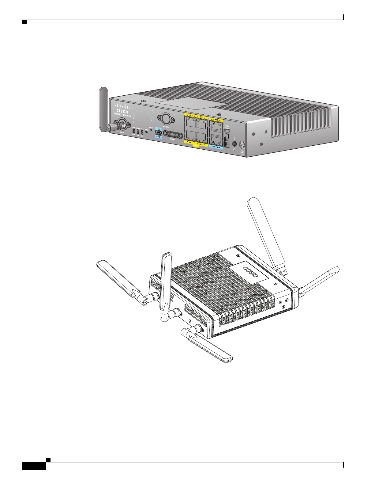
Figure 1-1 shows the Cisco 819HG ISR.
Figure 1-1 Cisco 819HG Integrated Services Router
Figure 1-2 shows the Cisco 819HGW ISR.
Figure 1-2 Cisco 819HGW Integrated Services Router
1-2
285479
Cisco 819 Series Integrated Services Routers Software Configuration Guide
OL-23590-02
Page 13

Chapter 1 Product Overview
SKU Information
For the complete list of SKUs available in Cisco 819 ISRs, see SKU Information.
New Features
This section lists the software, platform, and security features supported by the Cisco 819 ISRs.
• 3G Features, page 1-3
• WLAN Features, page 1-4
• 4G LTE Features, page 1-4
• Platform Features, page 1-4
• Security Features, page 1-4
Note The WAAS Express feature is not supported. This feature will be supported for 3G and 4G interfaces
with later IOS releases.
SKU Information
3G Features
• Modem control and management
• Asynchronous transport (AT) command set
• Wireless Host Interface Protocol (WHIP)
• Control and Status (CNS) for out-of-band modem control and status
• Diagnostic Monitor (DM) logging
• Account provisioning
• Modem firmware upgrade
• SIM locking and unlocking
• MEP unlocking
• OMA-DM activation
• Dual SIM card slots
• Link persistence
• SMS Services
• Global Positioning System (GPS) Services
• 3G MIB
OL-23590-02
Cisco 819 Series Integrated Services Routers Software Configuration Guide
1-3
Page 14

New Features
WLAN Features
• Dual Radio
• CleanAir Technology
• Dynamic Frequency Selection
4G LTE Features
• IPv4 bearer
• MIPv4, NEMOv4, RFC 3025
• IPv4 subnet behind LTE UE interface
• Evolved High-Rate Packet Data (EHRPD), which allows seamless handoff between 4G LTE and 3G
• Seamless hand-off between LTE and EHRPD network (C819(H)G-4G-V-K9 only)
• Support for UMTS service as a fallback option from LTE service (C819(H)G-4G-A-K9 and
• Seamless handoff between LTE and UMTS service (C819(H)G-4G-A-K9 and C819(H)G-4G-G-K9
• Remote access to Qualcomm diagnostic monitor port
Chapter 1 Product Overview
services (C819(H)G-4G-V-K9 only)
C819(H)G-4G-G-K9 only)
only)
• OTA-DM including wireless configuration FOTA (C819(HG-4G-V-K9 only)
• Mini USB type 2 connector for modem provisioning
Platform Features
For the complete list of Cisco 819 ISR platform features, see Platform Features for Cisco 819 ISRs.
Security Features
The Cisco 819 ISRs provide the following security features:
• Intrusion Prevention System (IPS)
• Dynamic Multipoint VPN (DMVPN)
• IPsec
• Quality of service (QoS)
• Firewall
• URL filtering
1-4
Cisco 819 Series Integrated Services Routers Software Configuration Guide
OL-23590-02
Page 15

CHAP T ER
2
Wireless Device Overview
The Cisco 819 ISRs provide Internet, VPN, data, and backup capability to corporate teleworkers and
remote and small offices of fewer than 20 users. These fixed routers are capable of bridging and
multiprotocol routing between LAN and WAN ports and provide advanced features such as antivirus
protection.
The fixed 3G routers can be used as the primary WAN connectivity and as a backup for critical
applications and can also be used as the primary WAN connection.
Note There are two SIM card slots in the Cisco 819 ISRs. For information on how to install the SIM cards,
see Cisco 819 Integrated Services Router Hardware Installation Guide.
• ScanSafe, page 2-1
• TFTP support with Ethernet WAN interface, page 2-2
• LEDs, page 2-2
ScanSafe
OL-23590-02
The Cisco Integrated Services Router G2 (ISR G2) family delivers numerous security services, including
firewall, intrusion prevention, and VPN. These security capabilities have been extended with Cisco ISR
Web Security with Cisco ScanSafe for a web security and web filtering solution that requires no
additional hardware or client software.
Cisco ISR Web Security with Cisco ScanSafe enables branch offices to intelligently redirect web traffic
to the cloud to enforce granular security and acceptable use policies over user web traffic. With this
solution, you can deploy market-leading web security quickly and can easily protect branch office users
from web-based threats, such as viruses, while saving bandwidth, money, and resources.
For more information, see Cisco ISR Web Security with Cisco ScanSafe Solution Guide.
Cisco 819 Series Integrated Services Routers Software Configuration Guide
2-1
Page 16

TFTP support with Ethernet WAN interface
TFTP support with Ethernet WAN interface
Trivial File Transfer Protocol (TFTP) is a file transfer protocol notable for its simplicity. It is generally
used for automated transfer of configuration or boot files between machines in a local environment.
The Cisco 819H ISR supports TFTP with Ethernet WAN interface that supports data transfer rate of 10
Mbps.
For more information, see the “Using the TFTP Download Command” section on page C-5.
Note This feature is supported in all Cisco 819 ISRs that have ROMMON version 15.2(2r)T and above.
Note TFTP download using switch port is supported in Cisco 819HGW SKUs only.
LEDs
Chapter 2 Wireless Device Overview
The LED is located on the front panel of the router. Table 2-1 describes the 3G LED for the Cisco 819
ISR.
Ta b l e 2-1 3G LED Descriptions
LED Color Description
SYS Yellow FPGA download is complete.
Green (blinking) ROMMON is operational.
Green (solid) IOS is operational.
Green (four blinks
during bootup)
Off After powering up, when FPGA is being downloaded (in
ACT Green Network activity on FE Switch ports, GE WAN port, 3G
Off No network activity.
WWAN Green Module is powered on and connected but not transmitting
Green (slow blinking) Module is powered on and searching for connection.
Green (fast blinking) Module is transmitting or receiving.
Off Module is not powered.
GPS Green (solid) Standalone GPS.
Green (slow blinking) GPS is acquiring.
Yellow (solid) Assisted GPS.
Yellow (slow blinking) Assisted GPS is acquiring.
Off GPS is not configured.
Reset button has been pushed during the bootup.
ROMMON).
cellular interface, and serial interfaces.
or receiving.
2-2
Cisco 819 Series Integrated Services Routers Software Configuration Guide
OL-23590-02
Page 17

Chapter 2 Wireless Device Overview
Table 2-1 3G LED Descriptions (continued)
LED Color Description
RSSI Green (solid) Signal > –60
1,2
SIM
3G One blink green and
1. Not applicable to Verizon and Sprint EVDO modems.
2. There is only one LED to indicate the status two SIMs. A one-blink pattern represents the status of the SIM in slot 0, followed
by a two-blink pattern for the SIM in slot 1.
Very strong signal
Green (four blinks and
then a long pause)
Green (two blinks and
then a long pause)
Green (one blink and
then a long pause)
Signal <= –60 to 74
Strong signal
Signal <= –75 to –89
Fair signal
Signal <= –90 to –109
Marginal signal
Off Signal <= –110
Unusable signal
Green / Yellow (one
SIM in slot 0 active, SIM in slot 1 is not.
green blink followed by
two yellow blinks)
Yellow / Green (one
SIM in slot 1 active, SIM in slot 0 is not.
yellow blink followed
by two greenblinks)
Off / Green (two green
No SIM in slot 0, SIM present in slot 1.
blinks and then pause)
Green / Off (Slow single
SIM present in slot0, no SIM in slot 1.
green blink and then
pause)
Off / Off No SIM present in either slots.
For 1xRTT, EGPRS, GPRS service.
then pause
Two blink green and
For EVDO, EVDO/1xRTT, UMTS.
then pause
Three blink green and
For EVDO/1xRTT RevA, HSPA, HSUPA/HSDPA.
then pause
Green (solid) For HSPA PLUS.
LEDs
OL-23590-02
Use the following show commands to check the LED status for your router:
• show platform led (for all LEDs)
• show controller cellular 0 (for 3G LEDs)
The following is a sample output from the show platform led command and shows the LED status:
router# show platform led
Cisco 819 Series Integrated Services Routers Software Configuration Guide
2-3
Page 18

LEDs
Chapter 2 Wireless Device Overview
LED STATUS:
==========
LEDS : SYSTEM WWAN RSSI GPS
STATUS: GREEN GREEN GREEN(2 BLINK) OFF
LEDS : ACTIVITY SIM(slot0 / slot1) 3G
STATUS: OFF GREEN / YELLOW GREEN
LAN PORTS : FE0 FE1 FE2 FE3
LINK/ENABLE LED : OFF OFF OFF OFF
SPEED LED : Unknown Unknown Unknown Unknown
PORT : GE-WAN0
LINK/ENABLE LED : OFF
SPEED LED : Unknown
The following is a sample output from the show controllers cellular command showing the 3G LED
status:
router# show controllers cellular 0
Interface Cellular0
3G Modem-QuadBand HSPA+R7/HSPA/UMTS QuadBand EDGE/GPRS Global and GPS,
Cellular modem configuration:
--------------------------GSM-Carrier Type : Cellular GSM Global.
SKU (PRI) Value: 9900198 .
Modem is recognized as valid
manufacture id: 0x00001199 product id: 0x000068A3
Sierra Wireless Mini Card MC8705 HSPA+R7 modem.
Cellular Dual SIM details:
---------------------------
SIM 0 is present
SIM 0 is active SIM
Modem Management Statistics
--------------------------Modem resets = 2
Last known modem state = 'application' mode
Packets sent = 2508, Packets received = 44621, Packets pending = 0
DIP MDM link status retry count = 0 pdp context = 0
DIP MDM link up pending = 0 pdp context = 0
IDB Cellular0: DIP profile id = 255
RSSI LED : 3-blink Green <<<<<<<<<<<<<<<<<<<<<<<<<<<<<<<<<<<<<
Service LED : 3-blink Green <<<<<<<<<<<<<<<<<<<<<<<<<<<<<<<<<<<<<
SIM LED : Slot0 - Green; Slot1 - Off <<<<<<<<<<<<<<<<<<<<<<<
GPS LED : Off <<<<<<<<<<<<<<<<<<<<<<<<<<<<<<<<<<<<<
GPS NMEA port = Disabled (Stream OFF)
DM port = Disabled
:
:
:
B
2-4
Cisco 819 Series Integrated Services Routers Software Configuration Guide
OL-23590-02
Page 19

CHAP T ER
3
Wireless Local Area Network
A Wireless Local Area Network (WLAN) implements a flexible data communication system frequently
augmenting rather than replacing a wired LAN within a building or campus. WLANs use radio frequency
to transmit and receive data over the air, minimizing the need for wired connections.
The Cisco 819HGW and Cisco 819HWD ISRs have a Host router software running on the first core. The
second core runs the WLAN Access Point software.
If WLAN is not supported in an SKU, all 1 GB DRAM memory is allocated to the first core. For the
SKUs that support WLAN, 128 MB out of the 1 GB main memory is allocated to the second core.
If WLAN is not supported in an SKU, all 1 GB compact flash memory is allocated to the first core. For
the SKUs that support WLAN, 64 MB out of the 1 GB main memory is allocated to the second core.
Note WLAN is only supported on Cisco 819HGW and Cisco 819HWD ISRs introduced in IOS release
15.2(4)M1.
WLAN Features
The Cisco 819HGW and Cisco 819HWD ISRs support the following features:
• Dual-Radio, page 3-1
• Images Supported, page 3-2
• CleanAir Technology, page 3-2
• Dynamic Frequency Selection, page 3-2
• LEDs, page 3-2
Dual-Radio
This release supports Cisco 802 Access Points (AP802). The AP802 is an integrated access point on the
Next Generation of Cisco 819HGW Cisco 819HWD ISRs.
The access point is a wireless LAN transceiver that acts as the connection point between wireless and
wired networks or as the center point of a standalone wireless network. In large installations, the roaming
functionality provided by multiple access points enables wireless users to move freely throughout the
facility while maintaining uninterrupted access to the network.
OL-23590-02
Cisco 819 Series Integrated Services Routers Software Configuration Guide
3-1
Page 20

WLAN Features
AP802 Dual Radio contains two different types of wireless radio that can support connections on both
2.4 GHz used by 802.11b, 802.11g, and 802.11n and 5 GHz used by 802.11a and 802.11n.
With the dual-radio/dual-band IEEE 802.11n access point, the Cisco 819HGW and Cisco 819HWD ISRs
offer a secure, integrated access point in a single device. The ISRs support both autonomous and unified
modes and are backward compatible with 802.11a/b/g.
The routers support IEEE 802.11n draft 2.0 and use multiple-input, multiple-output (MIMO) technology
that provides increased throughput, reliability, and predictability.
For complete information on how to configure wireless device and radio settings, see Basic Wireless
Device Configuration and Configuring Radio Settings.
Images Supported
For the images supported in the AP802 Dual radio, see Minimum software version needed to support
AP802.
CleanAir Technology
Chapter 3 Wireless Local Area Network
The CleanAir is a new wireless technology that intelligently avoids Radio Frequency (RF) to protect
802.11n performance. For more information, see
in all SKUs.
Dynamic Frequency Selection
The Dynamic Frequency Selection (DFS) is the process of detecting radar signals that must be protected
against 802.11a interference and upon detection switching the 802.11a operating frequency to one that
is not interfering with the radar systems. Transmit Power Control (TPC) is used to adapt the transmission
power based on regulatory requirements and range information.
Note The DFS functionality is disabled for FCC SKUs pending FCC certification. For more information, see
Dynamic Frequency Selection and IEEE 802.11h Transmit Power Control.
LEDs
The WLAN LED is located at the front panel of the router. Tab le 3-1 describes the WLAN LED for the
Cisco 819HGW and Cisco 819HWD ISRs.
Cisco CleanAir Technology. This feature is supported
3-2
Cisco 819 Series Integrated Services Routers Software Configuration Guide
OL-23590-02
Page 21

Chapter 3 Wireless Local Area Network
Ta b l e 3-1 WLAN LED Descriptions
WLAN LED Color Description
Boot loader
status sequence
Association
status
Operating status Blinking Blue Software upgrade in progress.
Boot loader
errors
Cisco IOS errors Red Software failure. Try to disconnect and reconnect the unit
WLAN Features
Blinking Green Board initialization in progress.
Initializing FLASH file system.
Initializing Ethernet.
Ethernet is OK.
Starting Cisco IOS.
Initialization successful.
Green Normal operating condition with no wireless client
associated.
Blue Normal operating condition with at least one wireless
client associated.
Rapidly cycling through
Access point location command invoked.
Blue, Green, Red, and
White
Blinking Red Ethernet link not operational.
Blinking Red and Blue FLASH file system failure.
Blinking Red and Off Environment variable failure.
Bad MAC address.
Ethernet failure during image recovery.
Boot environment failure.
No Cisco image file.
Boot failure.
power.
OL-23590-02
Cisco 819 Series Integrated Services Routers Software Configuration Guide
3-3
Page 22

WLAN Features
Chapter 3 Wireless Local Area Network
3-4
Cisco 819 Series Integrated Services Routers Software Configuration Guide
OL-23590-02
Page 23

CHAP T ER
4
4G LTE Wireless WAN
The Cisco 819HG-4G and Cisco 819G-4G LTE ISRs support 4G LTE and 3G cellular networks.
For instructions on how to configure the 4G LTE features on your Cisco 819 ISR, see the Cisco 4G LTE
Software Installation Guide.
OL-23590-02
Cisco 819 Series Integrated Services Routers Software Configuration Guide
4-1
Page 24

Chapter 4 4G LTE Wireless WAN
4-2
Cisco 819 Series Integrated Services Routers Software Configuration Guide
OL-23590-02
Page 25

CHAP T ER
5
Basic Router Configuration
This chapter provides procedures for configuring the basic parameters of your Cisco router, including
global parameter settings, routing protocols, interfaces, and command-line access. It also describes the
default configuration on startup.
• Interface Ports, page 5-2
• Default Configuration, page 5-2
• Information Needed for Configuration, page 5-3
• Configuring Command-Line Access, page 5-5
• Configuring Global Parameters, page 5-8
• Configuring WAN Interfaces, page 5-9
• Configuring a Loopback Interface, page 5-25
• Configuring Static Routes, page 5-27
• Configuring Dynamic Routes, page 5-28
OL-23590-02
Note Individual router models may not support every feature described in this guide. Features that are not
supported by a particular router are indicated whenever possible.
Note For instructions on how to configure the 4G LTE features on your Cisco 819 ISR, see the Cisco 4G LTE
Software Installation Guide.
This chapter includes configuration examples and verification steps, as available.
For complete information on how to access global configuration mode, see the “Entering Global
Configuration Mode” section on page A-5.
Cisco 819 Series Integrated Services Router Software Configuration Guide
5-1
Page 26

Interface Ports
Interface Ports
Table 5-1 lists the interfaces that are supported for each router and their associated port labels on the
equipment.
Ta b l e 5-1 Supported Interfaces and Associated Port Labels by Cisco Router
Router Interface Port Label
Cisco 819 Router 4-port Fast Ethernet LAN LAN, FE0–FE3
Gigabit Ethernet WAN GE WAN 0
Serial Serial
Mini USB for 3G port
3G RSVD
Provisioning
Console/Aux port CON/AUX
Chapter 5 Basic Router Configuration
Note There are two labels for the associated antennas with the labels: Main and DIV/GPS.
Default Configuration
When you first boot up your Cisco router, some basic configuration has already been performed. All of
the LAN and WAN interfaces have been created, console and vty ports are configured, and the inside
interface for Network Address Translation (NAT) has been assigned. Use the show
command to view the initial configuration, as shown in the following example for a Cisco 819 ISR:
Router# show running
Building configuration...
Current configuration : 977 bytes
!
version 15.1
service timestamps debug datetime msec
service timestamps log datetime msec
no service password-encryption
!
hostname Router
!
boot-start-marker
boot-end-marker
no aaa new-model
ip source-route
ip cef
no ipv6 cef
license udi pid CISCO819G-G-K9 sn FHK1429768Q
controller Cellular 0
interface Cellular0
no ip address
encapsulation ppp
interface Ethernet-wan0
no ip address
shutdown
duplex auto
running-config
5-2
Cisco 819 Series Integrated Services Router Software Configuration Guide
OL-23590-02
Page 27

Chapter 5 Basic Router Configuration
speed auto
interface FastEthernet0
interface FastEthernet1
interface FastEthernet2
interface FastEthernet3
interface Serial0
no ip address
shutdown
no fair-queue
clock rate 2000000
!
interface Vlan1
no ip address
!
ip forward-protocol nd
no ip http server
no ip http secure-server
logging esm config
control-plane
line con 0
no modem enable
line aux 0
line 3
no exec
line 7
stopbits 1
speed 115200
line vty 0 4
login
transport input all
!
scheduler allocate 20000 1000
end
Information Needed for Configuration
Information Needed for Configuration
You need to gather some or all of the following information, depending on your planned network
scenario, before configuring your network:
• If you are setting up an Internet connection, gather the following information:
–
PPP client name that is assigned as your login name
–
PPP authentication type: Challenge Handshake Authentication Protocol (CHAP) or Password
Authentication Protocol (PAP)
–
PPP password to access your Internet service provider (ISP) account
–
DNS server IP address and default gateways
• If you are setting up a connection to a corporate network, you and the network administrator must
generate and share the following information for the WAN interfaces of the routers:
–
PPP authentication type: CHAP or PAP
–
PPP client name to access the router
–
PPP password to access the router
Cisco 819 Series Integrated Services Router Software Configuration Guide
OL-23590-02
5-3
Page 28

Information Needed for Configuration
• If you are setting up IP routing:
–
Generate the addressing scheme for your IP network.
• If you are setting up the serial interface:
–
Mode of operation (sync, async, bisync)
–
Clock rate depending on the mode
–
IP address depending on the mode
• If you are setting up 3G:
–
You must have service availability on the Cisco 819 ISR from a carrier, and you must have
network coverage where your router will be physically placed. For a complete list of supported
carriers, see the data sheet at
–
You must subscribe to a service plan with a wireless service provider and obtain a SIM card.
–
You must install the SIM card before configuring the 3G Cisco 819 ISR. For instructions on how
to install the SIM card, see
3.7G (HSPA+)/3.5G (HSPA).
• You must install the required antennas before you configure the 3G for Cisco 819 ISR. See the
following URLs for instructions on how to install the antennas:
Chapter 5 Basic Router Configuration
Cisco 3G Wireless Connectivity Solutions.
Cisco 800 Series RoutersConfiguring Cisco EHWIC and 880G for
–
3G-ANTM1919D—See Cisco Multiband Swivel-Mount Dipole Antenna (3G-ANTM1919D).
–
3G-ANTM1916-CM—See Cisco Multiband Omnidirectional Ceiling Mount Antenna
(3G-ANTM1916-CM).
–
3G-AE015-R (Antenna Extension)—See Cisco Single-Port Antenna Stand for Multiband TNC
Male-Terminated Portable Antenna (Cisco 3G-AE015-R).
–
3G-AE010-R (Antenna Extension)—See Cisco Single-Port Antenna Stand for Multiband TNC
Male-Terminated Portable Antenna (Cisco 3G-AE015-R). This document applies to both
3G-AE015-R and 3G-AE010-R. The only difference between these two products is the length
of the cable.
–
3G-ANTM-OUT-OM—See Cisco 3G Omnidirectional Outdoor Antenna
(3G-ANTM-OUT-OM).
–
3G-ANTM-OUT-LP—See Cisco Multiband Omnidirectional Panel-Mount Antenna
(3G-ANTM-OUT-LP).
–
3G-ACC-OUT-LA—See Cisco 3G Lightning Arrestor (3G-ACC-OUT-LA).
–
4G-ANTM-OM-CM—See Cisco 4G Indoor Ceiling-Mount Omnidirectional Antenna
(4G-ANTM-OM-CM).
• You must check your LEDs for signal reception as described in Tab le 2-1.
• You should be familiar with the Cisco IOS software. See the Cisco IOS documentation beginning
with Release 12.4(15)T or later for Cisco 3G support.
• To configure your 3G data profile, you will need the username, password, and access point name
(APN) from your service provider:
5-4
After you have collected the appropriate information, you can perform a full configuration on your
router, beginning with the tasks in the
“Configuring Command-Line Access” section on page 5-5.
To obtain or change software licenses:
• See Software Activation on Cisco Integrated Services Routers and Cisco Integrated Service Routers
G2.
Cisco 819 Series Integrated Services Router Software Configuration Guide
OL-23590-02
Page 29

Chapter 5 Basic Router Configuration
Configuring Command-Line Access
To configure parameters to control access to the router, perform the following steps, beginning in global
configuration mode:
SUMMARY STEPS
1. line [aux | console | tty | vty] line-number
2. password password
3. login
4. exec-timeout minutes [seconds]
5. line [aux | console | tty | vty] line-number
6. password password
7. login
8. end
Configuring Command-Line Access
OL-23590-02
Cisco 819 Series Integrated Services Router Software Configuration Guide
5-5
Page 30

Configuring Command-Line Access
DETAILED STEPS
Step 1
Command Purpose
line [aux | console | tty | vty]
line-number
Example:
Router(config)# line console 0
Router(config-line)#
Enters line configuration mode and specifies the
type of line.
This example specifies a console terminal for
access.
Chapter 5 Basic Router Configuration
Step 2
Step 3
Step 4
Step 5
password password
Example:
Router(config)# password 5dr4Hepw3
Router(config-line)#
login
Example:
Router(config-line)# login
Router(config-line)#
exec-timeout minutes [seconds]
Example:
Router(config-line)# exec-timeout 5 30
Router(config-line)#
line [aux | console | tty | vty]
line-number
Example:
Router(config-line)# line vty 0 4
Router(config-line)#
Specifies a unique password for the console
terminal line.
Enables password checking at terminal session
login.
Sets the interval that the EXEC command
interpreter waits until user input is detected. The
default is 10 minutes. Optionally, add seconds to
the interval value.
This example shows a timeout of 5 minutes and
30
seconds. Entering a timeout of 0 0 specifies
never to time out.
Specifies a virtual terminal for remote console
access.
5-6
Step 6
password password
Example:
Router(config-line)# password aldf2ad1
Router(config-line)#
Cisco 819 Series Integrated Services Router Software Configuration Guide
Specifies a unique password for the virtual
terminal line.
OL-23590-02
Page 31

Chapter 5 Basic Router Configuration
Command Purpose
Step 7
login
Example:
Router(config-line)# login
Router(config-line)#
Configuring Command-Line Access
Enables password checking at the virtual terminal
session login.
Example
Step 8
end
Exits line configuration mode and returns to
privileged EXEC mode.
Example:
Router(config-line)# end
Router#
The following configuration shows the command-line access commands.
You do not need to input the commands marked “default.” These commands appear automatically in the
configuration file generated when you use the show running-config command.
!
line con 0
exec-timeout 10 0
password 4youreyesonly
login
transport input none (default)
stopbits 1 (default)
line vty 0 4
password secret
login
!
OL-23590-02
Cisco 819 Series Integrated Services Router Software Configuration Guide
5-7
Page 32

Configuring Global Parameters
Configuring Global Parameters
To configure selected global parameters for your router, perform these steps:
SUMMARY STEPS
1. configure terminal
2. hostname name
3. enable secret password
4. no ip domain-lookup
DETAILED STEPS
Command Purpose
Step 1
configure terminal
Example:
Router> enable
Router# configure terminal
Router(config)#
Chapter 5 Basic Router Configuration
Enters global configuration mode when using the
console port.
If you are connecting to the router using a remote
terminal, use the following:
telnet router name or address
Login: login id
Password: *********
Router> enable
Step 2
Step 3
Step 4
hostname name
Example:
Router(config)# hostname Router
Router(config)#
enable secret password
Example:
Router(config)# enable secret cr1ny5ho
Router(config)#
no ip domain-lookup
Example:
Router(config)# no ip domain-lookup
Router(config)#
Specifies the name for the router.
Specifies an encrypted password to prevent
unauthorized access to the router.
Disables the router from translating unfamiliar
words (typos) into IP addresses.
5-8
Cisco 819 Series Integrated Services Router Software Configuration Guide
OL-23590-02
Page 33

Chapter 5 Basic Router Configuration
Configuring WAN Interfaces
Configure the WAN interface for your router using one of the following as appropriate:
• Configuring a Gigabit Ethernet WAN Interface, page 5-9
• Configuring the Cellular Wireless WAN Interface, page 5-10
• Configuring Dual SIM for Cellular Networks, page 5-22
• Configuring Router for Image and Config Recovery Using Push Button, page 5-23
• Configuring Router for Image and Config Recovery Using Push Button, page 5-23
Configuring a Gigabit Ethernet WAN Interface
To configure the Ethernet interface on a Cisco 819 ISR, perform these steps, beginning in global
configuration mode:
SUMMARY STEPS
Configuring WAN Interfaces
1. interface type number
2. ip address ip-address mask
3. no shutdown
4. exit
OL-23590-02
Cisco 819 Series Integrated Services Router Software Configuration Guide
5-9
Page 34

Configuring WAN Interfaces
DETAILED STEPS
Step 1
Command Purpose
interface type number
Enters the configuration mode for a Gigabit
Ethernet WAN interface on the router.
Example:
Router(config)# interface gigabitethernet 0
Router(config-if)#
Chapter 5 Basic Router Configuration
Step 2
ip address ip-address mask
Example:
Router(config-if)# ip address 192.168.12.2
255.255.255.0
Router(config-if)#
Step 3
no shutdown
Example:
Router(config-if)# no shutdown
Router(config-if)#
Step 4
exit
Example:
Router(config-if)# exit
Router(config)#
Configuring the Cellular Wireless WAN Interface
The Cisco 819 ISRs provide a Third-Generation (3G) wireless interface for use over Global System for
Mobile Communications (GSM) and code division multiple access (CDMA) networks. The interface is
a 34-millimetre embedded mini express card.
Sets the IP address and subnet mask for the
specified Gigabit Ethernet interface.
Enables the Ethernet interface, changing its
state from administratively down to
administratively up.
Exits configuration mode for the Gigabit
Ethernet interface and returns to global
configuration mode.
5-10
Its primary application is WAN connectivity as a backup data link for critical data applications. However,
the 3G wireless interface can also function as the router’s primary WAN connection.
To configure the 3G cellular wireless interface, follow these guidelines and procedures:
• Prerequisites for Configuring the 3G Wireless Interface, page 5-11
• Restrictions for Configuring the Cellular Wireless Interface, page 5-11
• Data Account Provisioning, page 5-12
• Configuring a Cellular Interface, page 5-16
• Configuring DDR, page 5-17
• Examples for Configuring Cellular Wireless Interfaces, page 5-20
• Configuring Dual SIM for Cellular Networks, page 5-22
Cisco 819 Series Integrated Services Router Software Configuration Guide
OL-23590-02
Page 35

Chapter 5 Basic Router Configuration
Prerequisites for Configuring the 3G Wireless Interface
The following are prerequisites to configuring the 3G wireless interface:
• You must have wireless service from a carrier, and you must have network coverage where your
router will be physically placed. For a complete list of supported carriers, see the data sheet at:
www.cisco.com/go/m2m
• You must subscribe to a service plan with a wireless service provider and obtain a SIM card (GSM
modem only) from the service provider.
• You must check your LEDs for signal strength, as described in Tab le 2-1.
• You should be familiar with the Cisco IOS software. See Cisco IOS documentation beginning with
Cisco IOS Release 12.4(15)XZ or later for Cisco 3G Wireless support.
• To configure your GSM data profile, you need the following information from your service provider:
–
Username
–
Password
–
Access point name (APN)
• To configure your CDMA (CDMA only) data profile for manual activation, you need the following
information from your service provider:
–
Master Subsidy Lock (MSL) number
–
Mobile Directory number (MDN)
Configuring WAN Interfaces
–
Mobile Station Identifier (MSID)
–
Electronic Serial Number (ESN)
• Check the LED located on the front panel of the router for signal strength and other indications.
Table 2-1 describes the 3G LEDs for the Cisco 819 ISR.
Restrictions for Configuring the Cellular Wireless Interface
The following restrictions apply to configuring the Cisco 3G wireless interface:
• A data connection can be originated only by the 3G wireless interface. Remote dial-in is not
supported.
• Because of the shared nature of wireless communications, the experienced throughput varies
depending on the number of active users or the amount of congestion in a given network.
• Cellular networks have higher latency than wired networks. Latency rates depend on the technology
and carrier. Latency may be higher when there is network congestion.
• VoIP is currently not supported.
• Any restrictions that are part of the terms of service from your carrier also apply to the Cisco 3G
wireless interface.
• Inserting a different type of modem from what was previously removed requires configuration
changes and you must reload the system.
OL-23590-02
Cisco 819 Series Integrated Services Router Software Configuration Guide
5-11
Page 36

Configuring WAN Interfaces
Data Account Provisioning
Note To provision your modem, you must have an active wireless account with a service provider. A SIM card
must be installed in a GSM 3G wireless card.
To provision your data account, follow these procedures:
• Verifying Signal Strength and Service Availability, page 5-12
• Configuring a GSM Modem Data Profile, page 5-13
• CDMA Modem Activation and Provisioning, page 5-14
Verifying Signal Strength and Service Availability
To verify the signal strength and service availability on your modem, use the following commands in
privileged EXEC mode.
SUMMARY STEPS
Chapter 5 Basic Router Configuration
DETAILED STEPS
Command or Action Purpose
Step 1
show cellular 0 network
Example:
Router# show cellular 0 network
Step 2
show cellular 0 hardware
1. show cellular 0 network
2. show cellular 0 hardware
3. show cellular 0 connection
4. show cellular 0 gps
5. show cellular 0 radio
6. show cellular 0 profile
7. show cellular 0 security
8. show cellular 0 sms
9. show cellular 0 all
Displays information about the carrier network, cell
site, and available service.
Displays the cellular modem hardware information.
Step 3
5-12
Example:
Router# show cellular 0 hardware
show cellular 0 connection
Example:
Router# show cellular 0 connection
Cisco 819 Series Integrated Services Router Software Configuration Guide
Displays the current active connection state and data
statistics.
OL-23590-02
Page 37

Chapter 5 Basic Router Configuration
Command or Action Purpose
Step 4
show cellular 0 gps
Example:
Router# show cellular 0 gps
Step 5
show cellular 0 radio
Example:
Router# show cellular 0 radio
Step 6
show cellular 0 profile
Example:
Router# show cellular 0 profile
Step 7
show cellular 0 security
Example:
Router# show cellular 0 security
Step 8
show cellular 0 sms
Configuring WAN Interfaces
Displays the cellular gps information.
Shows the radio signal strength.
Note The RSSI should be better than –90 dBm for
steady and reliable connection.
Shows information about the modem data profiles
created.
Shows the security information for the modem, such
as SIM and modem lock status.
Displays the cellular sms information.
Example:
Router# show cellular 0 sms
Step 9
show cellular 0 all
Example:
Router# show cellular 0 all
Configuring a GSM Modem Data Profile
To configure or create a new modem data profile, enter the following command in privileged EXEC
mode.
SUMMARY STEPS
1. cellular 0 gsm profile create <profile number> <apn> <authentication> <username>
<password> ipv4
DETAILED STEPS
Command or Action Purpose
Step 1
cellular 0 gsm profile create <profile number> <apn>
<authentication> <username> <password> ipv4
Shows consolidated information about the modem,
such as the profiles that were created, the radio
signal strength, the network security, and so on.
Creates a new modem data profile. See Table 5-2 for
details about the command parameters.
Example:
Router# gsm profile create 2 <apn-name> chap
username password ipv4
OL-23590-02
Cisco 819 Series Integrated Services Router Software Configuration Guide
5-13
Page 38

Configuring WAN Interfaces
Table 5-2 lists the modem data profile parameters.
Ta b l e 5-2 Modem Data Profile Parameters
profile number Number for the profile that you are creating. You can create up to 16
apn Access point name. You must get this information from the service provider.
authentication Type of authentication, for example, CHAP, PAP.
Username Username provided by your service provider.
Password Password provided by your service provider.
CDMA Modem Activation and Provisioning
Activation procedures may differ, depending upon your carrier. Consult your carrier and perform one of
the following procedures as appropriate:
• Manual activation
• Activating using over-the-air service provisioning
The following table lists the activation and provisioning processes supported by different wireless
carriers.
Chapter 5 Basic Router Configuration
profiles.
Ta b l e 5-3
Activation and Provisioning Process Carrier
Manual Activation using MDN, MSID, MSL Sprint
OTASP1 Activation
IOTA2 for Data Profile refresh
1. OTASP = Over the Air Service Provisioning.
2. IOTA = Internet Over the Air.
Verizon Wireless
Sprint
Manual Activation
Note You must have valid mobile directory number (MDN), mobile subsidy lock (MSL), and mobile station
identifier (MSID) information from your carrier before you start this procedure.
To configure a modem profile manually, use the following command, beginning in EXEC mode:
cellular unit cdma activate manual mdn msid msl
Besides being activated, the modem data profile is provisioned through the Internet Over the Air (IOTA)
process. The IOTA process is initiated automatically when you use the cellular unit cdma activate
manual mdn msid msl command.
The following is a sample output from this command:
router# cellular 0 cdma activate manual 1234567890 1234567890 12345
NAM 0 will be configured and will become Active
Modem will be activated with following Parameters
MDN :1234567890; MSID :1234567890; SID :1234; NID 12:
Checking Current Activation Status
Modem activation status: Not Activated
Begin Activation
5-14
Cisco 819 Series Integrated Services Router Software Configuration Guide
OL-23590-02
Page 39

Chapter 5 Basic Router Configuration
Account activation - Step 1 of 5
Account activation - Step 2 of 5
Account activation - Step 3 of 5
Account activation - Step 4 of 5
Account activation - Step 5 of 5
Secure Commit Result: Succeed
Done Configuring - Resetting the modem
The activation of the account is Complete
Waiting for modem to be ready to start IOTA
Beginning IOTA
router#
*Feb 6 23:29:08.459: IOTA Status Message Received. Event: IOTA Start, Result: SUCCESS
*Feb 6 23:29:08.459: Please wait till IOTA END message is received
*Feb 6 23:29:08.459: It can take up to 5 minutes
*Feb 6 23:29:27.951: OTA State = SPL unlock, Result = Success
*Feb 6 23:29:32.319: OTA State = Parameters committed to NVRAM, Result = Success
*Feb 6 23:29:40.999: Over the air provisioning complete; Result:Success
*Feb 6 23:29:41.679: IOTA Status Message Received. Event: IOTA End, Result: SUCCESS
The IOTA start and end must have “success” as the resulting output. If you receive an error message, you
can run IOTA independently by using the cellular cdma activate iota command.
Your carrier may require periodic refreshes of the data profile. Use the following command to refresh
the data profile:
cellular cdma activate iota
Configuring WAN Interfaces
Activating with Over-the-Air Service Provisioning
To provision and activate your modem using Over-the-Air Service Provisioning (OTASP), use the
following command, beginning in EXEC mode.
router # cellular 0 cdma activate otasp phone_number
Note You need to obtain the phone number for use with this command from your carrier. The standard OTASP
calling number is *22899.
The following is a sample output from this command:
router# cellular 0 cdma activate otasp *22899
Beginning OTASP activation
OTASP number is *22899
819H#
OTA State = SPL unlock, Result = Success
router#
OTA State = PRL downloaded, Result = Success
OTA State = Profile downloaded, Result = Success
OTA State = MDN downloaded, Result = Success
OTA State = Parameters committed to NVRAM, Result = Success
Over the air provisioning complete; Result:Success
OL-23590-02
Cisco 819 Series Integrated Services Router Software Configuration Guide
5-15
Page 40

Configuring WAN Interfaces
Configuring a Cellular Interface
To configure the cellular interface, enter the following commands, beginning in privileged EXEC mode.
SUMMARY STEPS
1. configure terminal
2. interface cellular 0
3. encapsulation ppp
4. ppp chap hostname hostname
5. ppp chap password 0 password
6. asynchronous mode interactive
7. ip address negotiated
Note The PPP Challenge Handshake Authentication Protocol (CHAP) authentication parameters that you use
in this procedure must be the same as the username and password provided by your carrier and
configured only under the GSM profile. CDMA does not require a username or password.
Chapter 5 Basic Router Configuration
DETAILED STEPS
Command or Action Purpose
Step 1
configure terminal
Example:
Router# configure terminal
Step 2
interface cellular 0
Example:
Router (config)# interface cellular 0
Step 3
encapsulation ppp
Example:
Router (config-if)# encapsulation ppp
Step 4
ppp chap hostname hostname
Example:
Router (config-if)# ppp chap hostname cisco@wwan.ccs
Step 5
ppp chap password 0 password
Enters global configuration mode from the terminal.
Specifies the cellular interface.
Specifies PPP encapsulation for an interface
configured for dedicated asynchronous mode or
dial-on-demand routing (DDR).
Defines an interface-specific Challenge Handshake
Authentication Protocol (CHAP) hostname. This
must match the username given by the carrier.
Applies to GSM only.
Defines an interface-specific CHAP password. This
must match the password given by the carrier.
5-16
Example:
Router (config-if)# ppp chap password 0 cisco
Cisco 819 Series Integrated Services Router Software Configuration Guide
OL-23590-02
Page 41

Chapter 5 Basic Router Configuration
Command or Action Purpose
Step 6
asynchronous mode interactive
Example:
Router (config-if)# asynchronous mode interactive
Step 7
ip address negotiated
Example:
Router (config-if)# ip address negotiated
Note When the cellular interface requires a static IP address, the address may be configured as ip address
negotiated. Through IP Control Protocol (IPCP), the network ensures that the correct static IP address
is allocated to the device. If a tunnel interface is configured with the ip address unnumbered <cellular
interface> command, the actual static IP address must be configured under the cellular interface, in place
of ip address negotiated. For a sample cellular interface configuration, see the
Configuration” section on page 5-20.
Configuring WAN Interfaces
Returns a line from dedicated asynchronous network
mode to interactive mode, enabling the slip and ppp
commands in privileged EXEC mode.
Specifies that the IP address for a particular
interface is obtained via PPP and IPCP address
negotiation.
“Basic Cellular Interface
Configuring DDR
SUMMARY STEPS
Perform these steps to configure dial-on-demand routing (DDR) for the cellular interface.
1. configure terminal
2. interface cellular 0
3. dialer in-band
4. dialer idle-timeout seconds
5. dialer string string
6. dialer group number
7. exit
8. dialer-list dialer-group protocol protocol-name {permit | deny | list access-list-number |
access-group}
9. ip access-list <access list number> permit <ip source address>
10. line 3
11. script dialer <regexp>
12. exit
13. chat-script <script name> ”” “ATDT*99*<profile number>#” TIMEOUT <timeout value>
CONNECT
or
chat-script <script name> "" "ATDT*777*<profile number>#" TIMEOUT <timeout value>
CONNECT
OL-23590-02
14. interface cellular 0
15. dialer string <string>
Cisco 819 Series Integrated Services Router Software Configuration Guide
5-17
Page 42

Configuring WAN Interfaces
DETAILED STEPS
Command or Action Purpose
Step 1
configure terminal
Example:
Router# configure terminal
Step 2
interface cellular 0
Example:
Router (config)# interface cellular 0
Step 3
dialer in-band
Example:
Router (config-if)# dialer in-band
Step 4
dialer idle-timeout seconds
Chapter 5 Basic Router Configuration
Enters global configuration mode.
Specifies the cellular interface.
Enables DDR and configures the specified serial
interface for in-band dialing.
Specifies the duration of idle time, in seconds, after
which a line is disconnected.
Step 5
Step 6
Step 7
Step 8
Step 9
Example:
Router (config-if)# dialer idle-timeout 30
dialer string string
Example:
Router (config-if)# dialer string gsm
dialer-group number
Example:
Router (config-if)# dialer-group 1
exit
Example:
Router (config-if)# exit
dialer-list dialer-group protocol protocol-name
{permit | deny | list access-list-number |
access-group}
Example:
Router (config)# dialer-list 1 protocol ip list 1
ip access-list <access list number> permit <ip
source address>
Specifies the number or string to dial. Use the name
of the chat script here.
Specifies the number of the dialer access group to
which a specific interface belongs.
Enters the global configuration mode.
Creates a dialer list for traffic of interest and permits
access to an entire protocol.
Defines traffic of interest.
5-18
Example:
Router (config)# ip access list 1 permit any
Cisco 819 Series Integrated Services Router Software Configuration Guide
OL-23590-02
Page 43

Chapter 5 Basic Router Configuration
Command or Action Purpose
Step 10
line 3
Example:
Router (config-line)# line 3
Step 11
script dialer <regexp>
Example:
Router (config-line)# script-dialer gsm
Step 12
exit
Example:
Router (config-line)# exit
Step 13
For GSM:
chat-script <script name> ”” “ATDT*99*<profile
number>#” TIMEOUT <timeout value> CONNECT
For CDMA:
chat-script <script name> "" "ATDT*777*<profile
number>#" TIMEOUT <timeout value> CONNECT
Configuring WAN Interfaces
Specifies the line configuration mode. It is always 3.
Specifies a default modem chat script.
Exits line configuration mode.
Configures this line for GSM.
Configures this line for CDMA.
Step 14
Step 15
Example:
Router (config)# chat-script gsm "" "ATDT*98*2#"
TIMEOUT 60 "CONNECT“
interface cellular 0
Example:
Router (config)# interface cellular 0
dialer string string
Example:
Router (config)# dialer string gsm
Defines the Attention Dial Tone (ATDT) commands
when the dialer is initiated.
Specifies the cellular interface.
Specifies the dialer script (defined using the chat
script command).
OL-23590-02
Cisco 819 Series Integrated Services Router Software Configuration Guide
5-19
Page 44

Configuring WAN Interfaces
Examples for Configuring Cellular Wireless Interfaces
This section provides the following configuration examples:
• Basic Cellular Interface Configuration, page 5-20
• Tunnel over Cellular Interface Configuration, page 5-21
• Configuration for 8705 modem, page 5-21
Basic Cellular Interface Configuration
The following example shows how to configure a gsm cellular interface to be used as a primary WAN
connection. It is configured as the default route.
chat-script gsm "" "ATDT*98*2#" TIMEOUT 60 "CONNECT“
!
interface Cellular0
ip address negotiated
encapsulation ppp
dialer in-band
dialer string gsm
dialer-group 1
async mode interactive
ppp chap hostname cisco@wwan.ccs
ppp chap password 0 cisco
ppp ipcp dns request
!
Chapter 5 Basic Router Configuration
ip route 0.0.0.0 0.0.0.0 Cellular0
!
!
access-list 1 permit any
dialer-list 1 protocol ip list 1
!
line 3
exec-timeout 0 0
script dialer gsm
login
modem InOut
The following example shows how to configure a cdma cellular interface to be used as a primary WAN
connection. It is configured as the default route.
chat-script cdma "" "ATDT#777" TIMEOUT 60 "CONNECT“
!
interface Cellular0
ip address negotiated
encapsulation ppp
dialer in-band
dialer string cdma
dialer-group 1
async mode interactive
ppp chap password 0 cisco
!
ip route 0.0.0.0 0.0.0.0 Cellular0
!
!
access-list 1 permit any
dialer-list 1 protocol ip list 1
!
5-20
Cisco 819 Series Integrated Services Router Software Configuration Guide
OL-23590-02
Page 45

Chapter 5 Basic Router Configuration
line 3
exec-timeout 0 0
script dialer cdma
login
modem InOut
Tunnel over Cellular Interface Configuration
The following example shows how to configure the static IP address when a tunnel interface is
configured with the ip address unnumbered <cellular interface> command:
interface Tunnel2
ip unnumbered Cellular0
tunnel source Cellular0
tunnel destination 128.107.248.254
interface Cellular0
bandwidth receive 1400000
ip address 23.23.0.1 255.255.0.0
ip nat outside
ip virtual-reassembly
encapsulation ppp
no ip mroute-cache
dialer in-band
dialer idle-timeout 0
dialer string dial<carrier>
dialer-group 1
async mode interactive
no ppp lcp fast-start
ppp chap hostname <hostname> *** gsm only ***
ppp chap password 0 <password>
ppp ipcp dns request
! traffic of interest through the tunnel/cellular interface
ip route 10.10.0.0 255.255.0.0 Tunnel2
Configuring WAN Interfaces
Configuration for 8705 modem
The following shows how to configure an HSPA+ modem:
chat-script hspa "" "AT!SCACT=1,1" TIMEOUT 60 "OK"
interface Cellular0
ip address negotiated
encapsulation slip
dialer in-band
dialer pool-member 1
dialer-group 1
async mode interactive
interface Dialer1
ip address negotiated
ip nat outside
ip virtual-reassembly in
encapsulation slip
dialer pool 1
dialer string hspa
dialer-group 1
ip nat inside source list 1 interface Dialer1 overload
ip route 0.0.0.0 0.0.0.0 Dialer1
access-list 1 permit any
dialer-list 1 protocol ip permit
OL-23590-02
Cisco 819 Series Integrated Services Router Software Configuration Guide
5-21
Page 46

Chapter 5 Basic Router Configuration
Configuring WAN Interfaces
line 3
script dialer hspa+
modem InOut
no exec
transport input all
Configuring Dual SIM for Cellular Networks
The Dual SIM feature implements auto-switch and failover between two cellular networks on a Cisco
819 ISR. This feature is enabled by default with SIM slot 0 being the primary slot and slot 1 being the
secondary (failover) slot.
Note For instructions on how to configure the Dual SIM feature for 4G LTE cellular networks, see the Cisco
4G LTE Software Installation Guide.
You can configure the Dual SIM feature using the following commands:
Command Syntax Description
gsm failovertimer
gsm sim authenticate
gsm sim max-retry
gsm sim primary slot
gsm sim profile
gsm failovertimer <1-7>
gsm sim authenticate <0,7> <pin> slot <0-1>
gsm sim max-retry <0-65535>
gsm sim primary slot <0-1>
gsm sim profile <1-16> slot <0-1>
Sets the failover timer in minutes.
Verifies the SIM CHV1 code.
Specifies the maximum number of
failover retries. The default value is 10.
Modifies the primary slot assignment.
Configures the SIM profile.
Note the following:
• For auto-switch and failover to work, configure the SIM profile for slots 0 and 1 using the gsm sim
profile command.
• For auto-switch and failover to work, configure the chat script without a specific profile number.
• If no SIM profile is configured, profile #1 is used by default.
• If no GSM failover timer is configured, the default failover timeout is 2 minutes.
• If no GSM SIM primary slot is configured, the default primary SIM is slot 0.
The following example shows you how to set the SIM switchover timeout period to 3 minutes:
router(config-controller)# gsm failovertimer 3
The following example shows you how to authenticate using an unencrypted pin:
router(config-controller)# gsm sim authenticate 0 1234 slot 0
The following example shows you how to set the maximum number of SIM switchover retries to 20:
router(config-controller)# gsm sim max-retry 20
The following example shows you how to set SIM slot 1 as the primary slot:
router(config-controller)# gsm sim primary slot 1
5-22
Cisco 819 Series Integrated Services Router Software Configuration Guide
OL-23590-02
Page 47

Chapter 5 Basic Router Configuration
The following example shows you how to configure the SIM card in slot 0 to use profile 10:
router(config-controller)# gsm sim profile 10 slot 0
Perform the following commands to manually switch the SIM:
Command Syntax Description
cellular GSM SIM
gsm sim
gsm sim unblock
gsm sim change-pin
gsm sim activate slot
cellular GSM SIM {lock | unlock}
cellular <unit> gsm sim [lock | unlock] <pin>
cellular <unit> gsm sim unblock <puk> <newpin>
cellular <unit> gsm sim change-pin <oldpin>
<newpin>
cellular <unit> gsm sim activate slot <slot_no>
Locks or unlocks the SIM.
Locks or unlocks the gsm SIM.
Unblocks the gsm SIM.
Changes the PIN of the SIM.
Activates the GSM SIM.
The following command forces the modem to connect to SIM1:
Router# cellular 0 gsm sim activate slot 1
Configuring WAN Interfaces
Configuring Router for Image and Config Recovery Using Push Button
A push button feature is available on the Cisco 819 ISR. The reset button on the front panel of the router
enables this feature.
Perform the following steps to use this feature:
Step 1 Unplug power.
Step 2 Press the reset button on the front panel of the router.
Step 3 Power up the sytem while holding down the reset button.
The system LED blinks four times indicating that the router has accepted the button push.
Using this button takes effect only during ROMMON initialization. During a warm reboot, pressing this
button has no impact on performance.
pushed during ROMMON initialization.
Table 5-4 shows the high level functionality when the button is
OL-23590-02
Cisco 819 Series Integrated Services Router Software Configuration Guide
5-23
Page 48

Configuring WAN Interfaces
Ta b l e 5-4 Push Button Functionality during ROMMON Initialization
ROMMON Behavior IOS Behavior
• Boots using default baud rate.
• Performs auto-boot.
• Loads the *.default image if available on
Note If no *.default image is available, the
Examples of names for default images:
c800-universalk9-mz.SPA.default,
c-800-universalk9_npe-mz.151T.default,
image.default
Note You can only have one configuration file
compact flash
ROMMON will boot up with the first
Cisco IOS image on flash.
with *.cfg option. Having more than one
file will result in uncertain operational
behavior.
Chapter 5 Basic Router Configuration
If the configuration named *.cfg is available in
nvram storage or flash storage, IOS will perform a
backup of the original configuration and will boot
up using this configuration.
Note You can only have one configuration file
with *.cfg option. Having more than one
file will result in uncertain operational
behavior.
Use the show platform command to display the current bootup mode for the router. The following
sections show sample outputs when the button is not pushed and when the button is pushed.
Output When Button Is Not Pushed: Example
router# show platform boot-record
Platform Config Boot Record :
============================
Configuration Register at boot time : 0x0
Reset Button Status at Boot Time : Not Pressed
Startup-config Backup Status at Boot: No Status
Startup-config(backup file)location : No Backup
Golden config file at location : No Recovery Detected
Config Recovery Status : No Status
Output When Button Is Pushed: Example
router# show platform boot-record
Platform Config Boot Record :
============================
Configuration Register at boot time : 0x0
Reset Button Status at Boot Time : Pressed
Startup-config Backup Status at Boot: Ok
Startup-config(backup file)location : flash:/startup.backup.19000716-225840-UTC
Golden config file at location : flash:/golden.cfg
Config Recovery Status : Ok
5-24
Cisco 819 Series Integrated Services Router Software Configuration Guide
OL-23590-02
Page 49

Chapter 5 Basic Router Configuration
Push Button in WLAN AP
When the push button on the front panel is pressed, WLAN AP will perform both image and
configuration recovery.
To perform image recovery, WLAN will go into the boot loader so that the user can download the image
from the bootloader prompt.
To perform configuration recovery, WLAN AP will overwrite the contents of flash:/config.txt with the
contents of flash:/cpconfig-ap802.cfg file if available in flash drive. Otherwise, flash:/config.txt will
be deleted.
Configuring the Fast Ethernet LAN Interfaces
The Fast Ethernet LAN interfaces on your router are automatically configured as part of the default
VLAN and are not configured with individual addresses. Access is provided through the VLAN. You
may assign the interfaces to other VLANs if you want. For more information about creating VLANs, see
the
“Configuring the Ethernet Switches” section on page 10-1.
Configuring a Loopback Interface
Configuring a Loopback Interface
The loopback interface acts as a placeholder for the static IP address and provides default routing
information.
Perform these steps to configure a loopback interface, beginning in global configuration mode:
SUMMARY STEPS
1. interface type number
2. ip address ip-address mask
3. exit
OL-23590-02
Cisco 819 Series Integrated Services Router Software Configuration Guide
5-25
Page 50

Configuring a Loopback Interface
DETAILED STEPS
Step 1
Command Purpose
interface type number
Enters configuration mode for the loopback
interface.
Example:
Router(config)# interface Loopback 0
Router(config-if)#
Chapter 5 Basic Router Configuration
Example
Step 2
Step 3
ip address ip-address mask
Sets the IP address and subnet mask for the
loopback interface.
Example:
Router(config-if)# ip address 10.108.1.1
255.255.255.0
Router(config-if)#
exit
Exits configuration mode for the loopback
interface and returns to global configuration
Example:
Router(config-if)# exit
Router(config)#
mode.
The loopback interface in this sample configuration is used to support Network Address Translation
(NAT) on the virtual-template interface. This configuration example shows the loopback interface
configured on the Fast Ethernet interface with an IP address of 200.200.100.1/24, which acts as a static
IP address. The loopback interface points back to virtual-template1, which has a negotiated IP address.
!
interface loopback 0
ip address 200.200.100.1 255.255.255.0 (static IP address)
ip nat outside
!
interface Virtual-Template1
ip unnumbered loopback0
no ip directed-broadcast
ip nat outside
!
Verifying Configuration
To verify that you have properly configured the loopback interface, enter the show interface loopback
command. You should see a verification output similar to the following example:
Router# show interface loopback 0
Loopback0 is up, line protocol is up
Hardware is Loopback
Internet address is 200.200.100.1/24
MTU 1514 bytes, BW 8000000 Kbit, DLY 5000 usec,
reliability 255/255, txload 1/255, rxload 1/255
Encapsulation LOOPBACK, loopback not set
Last input never, output never, output hang never
Last clearing of "show interface" counters never
Queueing strategy: fifo
Cisco 819 Series Integrated Services Router Software Configuration Guide
5-26
OL-23590-02
Page 51

Chapter 5 Basic Router Configuration
Output queue 0/0, 0 drops; input queue 0/75, 0 drops
5 minute input rate 0 bits/sec, 0 packets/sec
5 minute output rate 0 bits/sec, 0 packets/sec
0 packets input, 0 bytes, 0 no buffer
Received 0 broadcasts, 0 runts, 0 giants, 0 throttles
0 input errors, 0 CRC, 0 frame, 0 overrun, 0 ignored, 0 abort
0 packets output, 0 bytes, 0 underruns
0 output errors, 0 collisions, 0 interface resets
0 output buffer failures, 0 output buffers swapped out
Another way to verify the loopback interface is to ping it:
Router# ping 200.200.100.1
Type escape sequence to abort.
Sending 5, 100-byte ICMP Echos to 200.200.100.1, timeout is 2 seconds:
!!!!!
Success rate is 100 percent (5/5), round-trip min/avg/max = 1/2/4 ms
Configuring Static Routes
Configuring Static Routes
SUMMARY STEPS
DETAILED STEPS
Step 1
Step 2
Static routes provide fixed routing paths through the network. They are manually configured on the
router. If the network topology changes, the static route must be updated with a new route. Static routes
are private routes unless they are redistributed by a routing protocol.
Follow these steps to configure static routes, beginning in global configuration mode.
1. ip route prefix mask {ip-address | interface-type interface-number [ip-address]}
2. end
Command Purpose
ip route prefix mask {ip-address |
interface-type interface-number
[ip-address]}
Example:
Router(config)# ip route 192.168.1.0
255.255.0.0 10.10.10.2
Router(config)#
end
Specifies the static route for the IP packets.
For details about this command and about
additional parameters that can be set, see
Cisco
IOS IP Routing: Protocol-Independent Command
Reference.
Exits router configuration mode and enters
privileged EXEC mode.
Example:
Router(config)# end
Router#
OL-23590-02
For general information on static routing, see the “Floating Static Routes” section on page B-5.
Cisco 819 Series Integrated Services Router Software Configuration Guide
5-27
Page 52

Configuring Dynamic Routes
Example
In the following configuration example, the static route sends out all IP packets with a destination IP
address of 192.168.1.0 and a subnet mask of 255.255.255.0 on the Fast Ethernet interface to another
device with an IP address of 10.10.10.2. Specifically, the packets are sent to the configured PVC.
You do not need to enter the command marked “(default).” This command appears automatically in the
configuration file generated when you use the show running-config command.
!
ip classless (default)
ip route 192.168.1.0 255.255.255.0 10.10.10.2!
Verifying Configuration
To verify that you have properly configured static routing, enter the show ip route command and look
for static routes signified by the “S.”
You should see a verification output similar to the following:
Router# show ip route
Codes: C - connected, S - static, R - RIP, M - mobile, B - BGP
D - EIGRP, EX - EIGRP external, O - OSPF, IA - OSPF inter area
N1 - OSPF NSSA external type 1, N2 - OSPF NSSA external type 2
E1 - OSPF external type 1, E2 - OSPF external type 2
i - IS-IS, su - IS-IS summary, L1 - IS-IS level-1, L2 - IS-IS level-2
ia - IS-IS inter area, * - candidate default, U - per-user static route
o - ODR, P - periodic downloaded static route
Chapter 5 Basic Router Configuration
Gateway of last resort is not set
10.0.0.0/24 is subnetted, 1 subnets
C 10.108.1.0 is directly connected, Loopback0
S* 0.0.0.0/0 is directly connected, FastEthernet0
Configuring Dynamic Routes
In dynamic routing, the network protocol adjusts the path automatically, based on network traffic or
topology. Changes in dynamic routes are shared with other routers in the network.
The Cisco routers can use IP routing protocols, such as Routing Information Protocol (RIP) or Enhanced
Interior Gateway Routing Protocol (EIGRP), to learn routes dynamically. You can configure either of
these routing protocols on your router.
• Configuring Routing Information Protocol, page 5-29
• Configuring Enhanced Interior Gateway Routing Protocol, page 5-30
5-28
Cisco 819 Series Integrated Services Router Software Configuration Guide
OL-23590-02
Page 53

Chapter 5 Basic Router Configuration
Configuring Routing Information Protocol
To configure the RIP routing protocol on the router, perform these steps, beginning in global
configuration mode:
SUMMARY STEPS
1. router rip
2. version {1 | 2}
3. network ip-address
4. no auto-summary
5. end
DETAILED STEPS
Command Task
Step 1
Step 2
router rip
Example:
Router> configure terminal
Router(config)# router rip
Router(config-router)#
version {1 | 2}
Configuring Dynamic Routes
Enters router configuration mode and enables RIP
on the router.
Specifies use of RIP version 1 or 2.
Step 3
Step 4
Step 5
Example:
Router(config-router)# version 2
Router(config-router)#
network ip-address
Specifies a list of networks on which RIP is to be
applied, using the address of the network of each
Example:
Router(config-router)# network 192.168.1.1
Router(config-router)# network 10.10.7.1
Router(config-router)#
no auto-summary
directly connected network.
Disables automatic summarization of subnet routes
into network-level routes. This allows subprefix
Example:
Router(config-router)# no auto-summary
Router(config-router)#
end
routing information to pass across classfull
network boundaries.
Exits router configuration mode and enters
privileged EXEC mode.
Example:
Router(config-router)# end
Router#
For general information on RIP, see the “RIP” section on page B-2.
OL-23590-02
Cisco 819 Series Integrated Services Router Software Configuration Guide
5-29
Page 54

Configuring Dynamic Routes
Example
The following configuration example shows RIP version 2 enabled in IP network 10.0.0.0 and
192.168.1.0.
To see this configuration, use the show running-config command from privileged EXEC mode.
!
Router# show running-config
router rip
version 2
network 10.0.0.0
network 192.168.1.0
no auto-summary
!
Verifying Configuration
To verify that you have properly configured RIP, enter the show ip route command and look for RIP
routes signified by “R.” You should see a verification output like the following example:
Router# show ip route
Codes: C - connected, S - static, R - RIP, M - mobile, B - BGP
D - EIGRP, EX - EIGRP external, O - OSPF, IA - OSPF inter area
N1 - OSPF NSSA external type 1, N2 - OSPF NSSA external type 2
E1 - OSPF external type 1, E2 - OSPF external type 2
i - IS-IS, su - IS-IS summary, L1 - IS-IS level-1, L2 - IS-IS level-2
ia - IS-IS inter area, * - candidate default, U - per-user static route
o - ODR, P - periodic downloaded static route
Chapter 5 Basic Router Configuration
Gateway of last resort is not set
10.0.0.0/24 is subnetted, 1 subnets
C 10.108.1.0 is directly connected, Loopback0
R 3.0.0.0/8 [120/1] via 2.2.2.1, 00:00:02, Ethernet0/0
Configuring Enhanced Interior Gateway Routing Protocol
To configure Enhanced Interior Gateway Routing Protocol (EIGRP), perform these steps, beginning in
global configuration mode:
SUMMARY STEPS
1. router eigrp as-number
2. network ip-address
3. end
5-30
Cisco 819 Series Integrated Services Router Software Configuration Guide
OL-23590-02
Page 55

Chapter 5 Basic Router Configuration
DETAILED STEPS
Command Purpose
Step 1
router eigrp as-number
Example:
Router(config)# router eigrp 109
Router(config)#
Configuring Dynamic Routes
Enters router configuration mode and enables
EIGRP on the router. The autonomous-system
number identifies the route to other EIGRP routers
and is used to tag the EIGRP information.
Example
Step 2
Step 3
network ip-address
Specifies a list of networks on which EIGRP is to
be applied, using the IP address of the network of
Example:
Router(config)# network 192.145.1.0
Router(config)# network 10.10.12.115
Router(config)#
end
directly connected networks.
Exits router configuration mode and enters
privileged EXEC mode.
Example:
Router(config-router)# end
Router#
For general information on EIGRP concept, see the “Enhanced IGRP” section on page B-3.
The following configuration example shows the EIGRP routing protocol enabled in IP networks
192.145.1.0 and 10.10.12.115. The EIGRP autonomous system number is 109.
To see this configuration, use the show running-config command, beginning in privileged EXEC mode.
!
router eigrp 109
network 192.145.1.0
network 10.10.12.115
!
Verifying Configuration
To verify that you have properly configured IP EIGRP, enter the show ip route command and look for
EIGRP routes indicated by “D.” You should see a verification output similar to the following:
Router# show ip route
Codes: C - connected, S - static, R - RIP, M - mobile, B - BGP
D - EIGRP, EX - EIGRP external, O - OSPF, IA - OSPF inter area
N1 - OSPF NSSA external type 1, N2 - OSPF NSSA external type 2
E1 - OSPF external type 1, E2 - OSPF external type 2
i - IS-IS, su - IS-IS summary, L1 - IS-IS level-1, L2 - IS-IS level-2
ia - IS-IS inter area, * - candidate default, U - per-user static route
o - ODR, P - periodic downloaded static route
Gateway of last resort is not set
10.0.0.0/24 is subnetted, 1 subnets
C 10.108.1.0 is directly connected, Loopback0
D 3.0.0.0/8 [90/409600] via 2.2.2.1, 00:00:02, Ethernet0/0
OL-23590-02
Cisco 819 Series Integrated Services Router Software Configuration Guide
5-31
Page 56

Configuring Dynamic Routes
Chapter 5 Basic Router Configuration
5-32
Cisco 819 Series Integrated Services Router Software Configuration Guide
OL-23590-02
Page 57

CHAP T ER
6
Configuring Backup Data Lines and Remote
Management
This chapter describes configuring backup data lines and remote management in the following sections:
• Configuring Backup Interfaces, page 6-1
• Configuring Cellular Dial-on-Demand Routing Backup, page 6-3
• Configuring Dial Backup and Remote Management Through the Console Port, page 6-8.
The Cisco 819 Integrated Services Router (ISR) supports backup data connectivity with a backup data
line that enables them to mitigate WAN downtime.
Cisco 819 ISRs also support remote management functions through the auxiliary port on any Cisco 819
series ISRs.
Note On the Cisco 819 ISRs, the console port and the auxiliary port are on the same physical RJ-45 port.
Therefore, the two ports cannot be activated simultaneously. You must use the command-line interface
(CLI) to enable the desired function.
Configuring Backup Interfaces
When the router receives an indication that the primary interface is down, the backup interface becomes
enabled. After the primary connection has been restored for a specified period, the backup interface is
disabled.
Even if the backup interface comes out of standby mode, the router does not enable the backup interface
unless the router receives the traffic specified for that backup interface.
Table 6-1 shows the backup interfaces available for each Cisco 819 ISR, along with their port
designations. Basic configurations for these interfaces are given in the “Configuring WAN Interfaces”
section on page 5-9.
Ta b l e 6-1 Model Number and Data Line Backup Capabilities
Router Model Number 3G
819 Yes
Cisco 819 Series Integrated Services Routers Software Configuration Guide
OL-23590-02
6-1
Page 58

Configuring Backup Interfaces
SUMMARY STEPS
DETAILED STEPS
Step 1
Chapter 6 Configuring Backup Data Lines and Remote Management
To configure your router with a backup interface, perform these steps, beginning in global configuration
mode:
1. interface type number
2. backup interface interface-type interface-number
3. exit
Command Purpose
interface type number
Enters interface configuration mode for the
interface for which you want to configure backup.
Example:
Router(config)# interface xxx 0
Router(config-if)#
This can be a serial interface, ISDN interface, or
asynchronous interface.
Step 2
Step 3
backup interface interface-type
interface-number
Example:
Router(config-if)# backup interface serial
0
Router(config-if)#
exit
Example:
Router(config-if)# exit
Router(config)#
Assigns an interface as the secondary or backup
interface.
This can be a serial interface or asynchronous
interface. For example, a serial 1 interface could
be configured to back up a serial 0 interface.
The example shows a serial interface configured
as the backup interface for the ATM 0 interface.
Exits the configuration interface mode.
6-2
Cisco 819 Series Integrated Services Routers Software Configuration Guide
OL-23590-02
Page 59

Chapter 6 Configuring Backup Data Lines and Remote Management
Configuring Cellular Dial-on-Demand Routing Backup
Configuring Cellular Dial-on-Demand Routing Backup
To monitor the primary connection and initiate the backup connection over the cellular interface when
needed, the router can use one of the following methods:
• Backup Interface—The backup interface that stays in standby mode until the primary interface line
protocol is detected as down and then is brought up. See the
section on page 6-1.
• Dialer Watch—Dialer watch is a backup feature that integrates dial backup with routing capabilities.
See the
• Floating Static Route—The route through the backup interface has an administrative distance that
“Configuring DDR Backup Using Dialer Watch” section on page 6-3.
is greater than the administrative distance of the primary connection route and therefore would not
be in the routing table until the primary interface goes down. When the primary interaface goes
down, the floating static route is used. See the
“Configuring DDR Backup Using Floating Static
Route” section on page 6-5
Note You cannot configure a backup interface for the cellular interface and any other asynchronous serial
interface.
“Configuring Backup Interfaces”
Configuring DDR Backup Using Dialer Watch
To initiate dialer watch, you must configure the interface to perform dial-on-demand routing (DDR) and
backup. Use traditional DDR configuration commands, such as dialer maps, for DDR capabilities. To
enable dialer watch on the backup interface and create a dialer list, use the following commands in
interface configuration mode.
SUMMARY STEPS
1. configure terminal
2. interface type number
3. dialer watch group group-number
4. dialer watch-list group-number ip ip-address address-mask
5. dialer-list <dialer-group> protocol <protocol name> {permit | deny | list <access list number> |
access-group}
6. ip access-list <access list number> permit <ip source address>
7. interface cellular 0
8. dialer string <string>
OL-23590-02
Cisco 819 Series Integrated Services Routers Software Configuration Guide
6-3
Page 60

Configuring Cellular Dial-on-Demand Routing Backup
DETAILED STEPS
Command or Action Purpose
Step 1
configure terminal
Example:
Router# configure terminal
Step 2
interface type number
Example:
Router (config)# interface 0
Step 3
dialer watch-group
group-number
Example:
Router(config-if)# dialer watch-group 2
Step 4
dialer watch-list group-number ip ip-address
address-mask
Chapter 6 Configuring Backup Data Lines and Remote Management
Enters global configuration mode.
Specifies the interface.
Enables dialer watch on the backup interface.
Defines a list of all IP addresses to be watched.
Step 5
Step 6
Step 7
Step 8
Example:
Router(config-if)# dialer watch-list 2 ip 10.4.0.254
255.255.0.0
dialer-list <dialer-group> protocol <protocol-name>
{permit | deny | list <access-list-number> |
access-group}
Example:
Router(config)# dialer-list 2 protocol ip permit
ip access-list <access list number> permit <ip
source address>
Example:
Router(config)# access list 2 permit 10.4.0.0
interface cellular 0
Example:
Router (config)# interface cellular 0
dialer string <string>
or
dialer group <dialer group number>
Creates a dialer list for traffic of interest and permits
access to an entire protocol.
Defines traffic of interest.
Do not use the access list permit all command to
avoid sending traffic to the IP network. This may
result in call termination.
Specifies the cellular interface.
CDMA only. Specifies the dialer script (defined
using the chat script command).
GSM only. Maps a dialer list to the dialer interface.
Example:
Router (config-if)# dialer string cdma *** cdma ***
or
Router (config-if)# dialer group 2 *** gsm ***
Cisco 819 Series Integrated Services Routers Software Configuration Guide
6-4
OL-23590-02
Page 61

Chapter 6 Configuring Backup Data Lines and Remote Management
Configuring Cellular Dial-on-Demand Routing Backup
Configuring DDR Backup Using Floating Static Route
To configure a floating static default route on the secondary interface, use the following commands,
beginning in the global configuration mode.
Note Make sure you have ip classless enabled on your router.
SUMMARY STEPS
1. configure terminal
2. ip route network-number network-mask {ip address | interface} [administrative distance] [name
name]
DETAILED STEPS
Command or Action Purpose
Step 1
configure terminal
Enters global configuration mode from the terminal.
Example:
Router# configure terminal
Step 2
ip route network-number network-mask
{ip-address | interface} [administrative distance]
[name name]
Establishes a floating static route with the
configured administrative distance through the
specified interface.
A higher administrative distance should be
Example:
Router (config)# ip route 0.0.0.0 Dialer 2 track 234
configured for the route through the backup
interface, so that the backup interface is used only
when the primary interface is down.
Cellular Wireless Modem as Backup with NAT and IPsec Configuration
The following example shows how to configure the 3G wireless modem as backup with NAT and IPsec
on either GSM or CDMA networks.
Note The receive and transmit speeds cannot be configured. The actual throughput depends on the cellular
network service.
Current configuration : 3433 bytes
!
version 12.4
no service pad
service timestamps debug datetime msec
service timestamps log datetime msec
no service password-encryption
!
hostname Router
!
boot-start-marker
boot-end-marker
OL-23590-02
Cisco 819 Series Integrated Services Routers Software Configuration Guide
6-5
Page 62

Configuring Cellular Dial-on-Demand Routing Backup
!
!
no aaa new-model
!
!
!
!
crypto isakmp policy 1
encr 3des
authentication pre-share
crypto isakmp key gsm address 128.107.241.234
!
!
crypto ipsec transform-set gsm ah-sha-hmac esp-3des
!
crypto map gsm1 10 ipsec-isakmp
set peer 128.107.241.234
set transform-set gsm
match address 103
!
!
!
no ip dhcp use vrf connected
ip dhcp excluded-address 10.4.0.254
!
ip dhcp pool gsmpool
network 10.4.0.0 255.255.0.0
dns-server 66.209.10.201 66.102.163.231
default-router 10.4.0.254
!
!
ip cef
!
no ipv6 cef
multilink bundle-name authenticated
chat-script gsm "" "atdt*98*1#" TIMEOUT 30 "CONNECT"
!
!
archive
log config
hidekeys
!
!
interface 0
no ip address
ip virtual-reassembly
load-interval 30
no ilmi-keepalive
!
interface 0.1 point-to-point
backup interface Cellular0
ip nat outside
ip virtual-reassembly
pvc 0/35
pppoe-client dial-pool-number 2
!
!
interface FastEthernet0
!
interface FastEthernet1
!
interface FastEthernet2
!
interface FastEthernet3
Chapter 6 Configuring Backup Data Lines and Remote Management
6-6
Cisco 819 Series Integrated Services Routers Software Configuration Guide
OL-23590-02
Page 63

Chapter 6 Configuring Backup Data Lines and Remote Management
!
interface Cellular0
ip address negotiated
ip nat outside
ip virtual-reassembly
encapsulation ppp
no ip mroute-cache
dialer in-band
dialer idle-timeout 0
dialer string gsm
dialer-group 1
async mode interactive
no ppp lcp fast-start
ppp chap hostname chunahayev@wwan.ccs
ppp chap password 0 B7uhestacr
ppp ipcp dns request
crypto map gsm1
!
interface Vlan1
description used as default gateway address for DHCP clients
ip address 10.4.0.254 255.255.0.0
ip nat inside
ip virtual-reassembly
!
interface Dialer2
ip address negotiated
ip mtu 1492
ip nat outside
ip virtual-reassembly
encapsulation ppp
load-interval 30
dialer pool 2
dialer-group 2
ppp authentication chap callin
ppp chap password 0 cisco
ppp ipcp dns request
crypto map gsm1
!
ip local policy route-map track-primary-if
ip forward-protocol nd
ip route 0.0.0.0 0.0.0.0 Dialer2 track 234
ip route 0.0.0.0 0.0.0.0 Cellular0 254
no ip http server
no ip http secure-server
!
!
ip nat inside source route-map nat2cell interface Cellular0 overload
!
ip sla 1
icmp-echo 209.131.36.158 source-interface Dialer2
timeout 1000
frequency 2
ip sla schedule 1 life forever start-time now
access-list 1 permit any
access-list 2 permit 10.4.0.0 0.0.255.255
access-list 3 permit any
access-list 101 permit ip 10.4.0.0 0.0.255.255 any
access-list 102 permit icmp any host 209.131.36.158
access-list 103 permit ip host 166.136.225.89 128.107.0.0 0.0.255.255
access-list 103 permit ip host 75.40.113.246 128.107.0.0 0.0.255.255
dialer-list 1 protocol ip list 1
dialer-list 2 protocol ip permit
!
!
Configuring Cellular Dial-on-Demand Routing Backup
OL-23590-02
Cisco 819 Series Integrated Services Routers Software Configuration Guide
6-7
Page 64

Configuring Dial Backup and Remote Management Through the Console Port
!
route-map track-primary-if permit 10
match ip address 102
set interface Dialer2
!
route-map nat2cell permit 10
match ip address 101
match interface Cellular0
!
!
control-plane
!
!
line con 0
no modem enable
line aux 0
line 3
exec-timeout 0 0
script dialer gsm
login
modem InOut
no exec
line vty 0 4
login
!
scheduler max-task-time 5000
!
webvpn cef
end
Chapter 6 Configuring Backup Data Lines and Remote Management
Configuring Dial Backup and Remote Management Through the
Console Port
When customer premises equipment, such as a Cisco 819 ISR, is connected to an ISP, an IP address is
dynamically assigned to the router or the IP address may be assigned by the router peer through the
centrally managed function. The dial backup feature can be added to provide a failover route in case the
primary line fails. The Cisco 819 ISRs can use the auxiliary port for dial backup and remote
management.
6-8
Cisco 819 Series Integrated Services Routers Software Configuration Guide
OL-23590-02
Page 65

Chapter 6 Configuring Backup Data Lines and Remote Management
82269
A1
3
2
2
C
B
BC
2
Internet
PSTN
Figure 6-1 shows the network configuration used for remote management access and for providing
backup to the primary WAN line.
Figure 6-1 Dial Backup and Remote Management Through the Auxiliary Port
Configuring Dial Backup and Remote Management Through the Console Port
1 Cisco 819 router A Main WAN link; primary connection to Internet service provider
2 Modem B Dial backup; serves as a failover link for Cisco 819 routers when
primary line goes down
3 PC C Remote management; serves as dial-in access to allow changes or
updates to Cisco IOS configurations
Cisco 819 Series Integrated Services Routers Software Configuration Guide
OL-23590-02
6-9
Page 66

Configuring Dial Backup and Remote Management Through the Console Port
To configure dial backup and remote management for these routers, perform these steps, beginning in
global configuration mode:
SUMMARY STEPS
1. ip name-server server-address
2. ip dhcp pool name
3. exit
4. chat-script script-name expect-send
5. interface type number
6. exit
7. interface type number
8. dialer watch-group group-number
9. exit
10. ip nat inside source {list access-list-number}{interface type number | pool name} [overload]
11. ip route prefix mask {ip-address | interface-type interface-number [ip-address]}
12. access-list access-list-number {deny | permit} source [source-wildcard]
Chapter 6 Configuring Backup Data Lines and Remote Management
13. dialerwatch-list group-number {ip ip-address address-mask | delay route-check initial seconds}
14. line [aux | console | tty | vty] line-number [ending-line-number]
15. modem enable
16. exit
17. line [aux | console | tty | vty] line-number [ending-line-number]
18. flowcontrol {none | software [lock] [in | out] | hardware [in | out]}
6-10
Cisco 819 Series Integrated Services Routers Software Configuration Guide
OL-23590-02
Page 67

Chapter 6 Configuring Backup Data Lines and Remote Management
DETAILED STEPS
Command Purpose
Step 1
ip name-server server-address
Example:
Router(config)#ip name-server 192.168.28.12
Router(config)#
Configuring Dial Backup and Remote Management Through the Console Port
Enters your ISP DNS IP address.
Tip You may add multiple server addresses if
available.
Step 2
Step 3
Step 4
Step 5
Step 6
ip dhcp pool name
Example:
Router(config)#ip dhcp pool 1
Router(config-dhcp)#
exit
Example:
Router(config-dhcp)#exit
Router(config)#
chat-script script-name expect-send
Example:
Router(config)# chat-script Dialout ABORT
ERROR ABORT BUSY ““ “AT” OK “ATDT 5555102
T” TIMEOUT 45 CONNECT \c
Router(config)#
interface type number
Example:
Router(config)# interface Async 1
Router(config-if)#
exit
Creates a DHCP address pool on the router and
enters DHCP pool configuration mode. The name
argument can be a string or an integer.
• Configure the DHCP address pool. For
sample commands that you can use in DHCP
pool configuration mode, see the
“Example”
section on page 6-13.
Exits config-dhcp mode and enters global
configuration mode.
Configures a chat script used in dial-on-demand
routing (DDR) to give commands for dialing a
modem and for logging in to remote systems. The
defined script is used to place a call over a modem
connected to the PSTN.
Creates and enters configuration mode for the
asynchronous interface.
Configure the asynchronous interface. For sample
commands that you can use in asynchronous
interface configuration mode, see the
“Example”
section on page 6-13.
Enters global configuration mode.
OL-23590-02
Step 7
Example:
Router(config-if)# exit
Router(config)#
interface type number
Example:
Router(config)# interface Dialer 3
Router(config-if)#
Cisco 819 Series Integrated Services Routers Software Configuration Guide
Creates and enters configuration mode for the
dialer interface.
6-11
Page 68

Configuring Dial Backup and Remote Management Through the Console Port
Command Purpose
Step 8
dialer watch-group group-number
Example:
Router(config-if)# dialer watch-group 1
Router(config-if)#
Chapter 6 Configuring Backup Data Lines and Remote Management
Specifies the group number for the watch list.
Step 9
Step 10
Step 11
Step 12
exit
Example:
Router(config-if)# exit
Router(config)#
ip nat inside source {list
access-list-number} {interface type number
| pool name} [overload]
Example:
Router(config)# ip nat inside source list
101 interface Dialer 3 overload
ip route prefix mask {ip-address |
interface-type interface-number
[ip-address]}
Example:
Router(config)# ip route 0.0.0.0 0.0.0.0
22.0.0.2
Router(config)#
access-list access-list-number {deny |
permit} source [source-wildcard]
Exits the interface configuration mode.
Enables dynamic translation of addresses on the
inside interface.
Sets the IP route to point to the dialer interface as
a default gateway.
Defines an extended access list that indicates
which addresses need translation.
6-12
Example:
Router(config)# access-list 1 permit
192.168.0.0 0.0.255.255 any
Step 13
dialerwatch-list group-number {ip
ip-address address-mask | delay route-check
initial seconds}
Example:
Router(config)# dialer watch-list 1 ip
22.0.0.2 255.255.255.255
Router(config)#
Step 14
line [aux | console | tty | vty]
line-number [ending-line-number]
Example:
Router(config)# line console 0
Router(config-line)#
Cisco 819 Series Integrated Services Routers Software Configuration Guide
Evaluates the status of the primary link, based on
the existence of routes to the peer. The address
22.0.0.2 is the peer IP address of the ISP.
Enters configuration mode for the line interface.
OL-23590-02
Page 69

Chapter 6 Configuring Backup Data Lines and Remote Management
Command Purpose
Step 15
modem enable
Example:
Router(config-line)# modem enable
Router(config-line)#
Configuring Dial Backup and Remote Management Through the Console Port
Switches the port from console to auxiliary port
function.
Example
Step 16
Step 17
Step 18
exit
Exits the configure interface mode.
Example:
Router(config-line)# exit
Router(config)#
line [aux | console | tty | vty]
line-number [ending-line-number]
Enters configuration mode for the auxiliary
interface.
Example:
Router(config)# line aux 0
Router(config)#
flowcontrol {none | software [lock] [in |
out] | hardware [in | out]}
Enables hardware signal flow control.
Example:
Router(config)# flowcontrol hardware
Router(config)#
The following configuration example specifies an IP address for the interface through PPP and IPCP
address negotiation and dial backup over the console port:
!
ip name-server 192.168.28.12
ip dhcp excluded-address 192.168.1.1
!
ip dhcp pool 1
import all
network 192.168.1.0 255.255.255.0
default-router 192.168.1.1
!
! Need to use your own correct ISP phone number.
modemcap entry MY-USER_MODEM:MSC=&F1S0=1
chat-script Dialout ABORT ERROR ABORT BUSY ““ “AT” OK “ATDT 5555102\T”
TIMEOUT 45 CONNECT \c
!
!
!
!
interface vlan 1
ip address 192.168.1.1 255.255.255.0
ip nat inside
ip tcp adjust-mss 1452
hold-queue 100 out
!
OL-23590-02
Cisco 819 Series Integrated Services Routers Software Configuration Guide
6-13
Page 70

Configuring Dial Backup and Remote Management Through the Console Port
! Dial backup and remote management physical interface.
interface Async1
no ip address
encapsulation ppp
dialer in-band
dialer pool-member 3
async default routing
async dynamic routing
async mode dedicated
ppp authentication pap callin
!
interface ATM0
mtu 1492
no ip address
no atm ilmi-keepalive
pvc 0/35
pppoe-client dial-pool-number 1
!
! Primary WAN link.
interface Dialer1
ip address negotiated
ip nat outside
encapsulation ppp
dialer pool 1
ppp authentication pap callin
ppp pap sent-username account password 7 pass
ppp ipcp dns request
ppp ipcp wins request
ppp ipcp mask request
!
! Dialer backup logical interface.
interface Dialer3
ip address negotiated
ip nat outside
encapsulation ppp
no ip route-cache
no ip mroute-cache
dialer pool 3
dialer idle-timeout 60
dialer string 5555102 modem-script Dialout
dialer watch-group 1
!
! Remote management PC IP address.
peer default ip address 192.168.2.2
no cdp enable
!
! Need to use your own ISP account and password.
ppp pap sent-username account password 7 pass
ppp ipcp dns request
ppp ipcp wins request
ppp ipcp mask request
!
! IP NAT over Dialer interface using route-map.
ip nat inside source route-map main interface Dialer1 overload
ip nat inside source route-map secondary interface Dialer3 overload
ip classless
!
! When primary link is up again, distance 50 will override 80 if dial backup
! has not timed out. Use multiple routes because peer IP addresses are alternated
! among them when the CPE is connected.
ip route 0.0.0.0 0.0.0.0 64.161.31.254 50
ip route 0.0.0.0 0.0.0.0 66.125.91.254 50
ip route 0.0.0.0 0.0.0.0 64.174.91.254 50
ip route 0.0.0.0 0.0.0.0 63.203.35.136 80
Chapter 6 Configuring Backup Data Lines and Remote Management
6-14
Cisco 819 Series Integrated Services Routers Software Configuration Guide
OL-23590-02
Page 71

Chapter 6 Configuring Backup Data Lines and Remote Management
ip route 0.0.0.0 0.0.0.0 63.203.35.137 80
ip route 0.0.0.0 0.0.0.0 63.203.35.138 80
ip route 0.0.0.0 0.0.0.0 63.203.35.139 80
ip route 0.0.0.0 0.0.0.0 63.203.35.140 80
ip route 0.0.0.0 0.0.0.0 63.203.35.141 80
ip route 0.0.0.0 0.0.0.0 Dialer1 150
no ip http server
ip pim bidir-enable
!
! PC IP address behind CPE.
access-list 101 permit ip 192.168.0.0 0.0.255.255 any
access-list 103 permit ip 192.168.0.0 0.0.255.255 any
!
! Watch multiple IP addresses because peers are alternated
! among them when the CPE is connected.
dialer watch-list 1 ip 64.161.31.254 255.255.255.255
dialer watch-list 1 ip 64.174.91.254 255.255.255.255
dialer watch-list 1 ip 64.125.91.254 255.255.255.255
!
! Dial backup will kick in if primary link is not available
! 5 minutes after CPE starts up.
dialer watch-list 1 delay route-check initial 300
dialer-list 1 protocol ip permit
!
! Direct traffic to an interface only if the dialer is assigned an IP address.
route-map main permit 10
match ip address 101
match interface Dialer1
!
route-map secondary permit 10
match ip address 103
match interface Dialer3
!
! Change console to aux function.
line con 0
exec-timedout 0 0
modem enable
stopbits 1
line aux 0
exec-timeout 0 0
! To enable and communicate with the external modem properly.
script dialer Dialout
modem InOut
modem autoconfigure discovery
transport input all
stopbits 1
speed 115200
flowcontrol hardware
line vty 0 4
exec-timeout 0 0
password cisco
login
!
scheduler max-task-time 5000
end
Configuring Dial Backup and Remote Management Through the Console Port
OL-23590-02
Cisco 819 Series Integrated Services Routers Software Configuration Guide
6-15
Page 72

Configuring Dial Backup and Remote Management Through the Console Port
Chapter 6 Configuring Backup Data Lines and Remote Management
6-16
Cisco 819 Series Integrated Services Routers Software Configuration Guide
OL-23590-02
Page 73

CHAP T ER
7
Environmental and Power Management
The Cisco 819 integrated services routers are equipped with sensors in the router body for monitoring
the environment temperature and logging the temperature every 30 seconds.There are four sensors
located on the four corners of the router chassis. There is an additonal System Ambient sensor and a 3G
sensor.
The corner sensors display the following message:
• Error message on the console—When the temperature ranges are outside the set temperature
thresholds, the monitor displays an error message. Different temperature ranges are set for different
SKUs of the router:
–
Cisco 819G (non-hardened): 0 to 60 degrees celcius
–
Cisco 819HG (hardened): –25 to 75 degrees celcius
• SNMP Traps—syslog messages are created when the temperature is outside the specified range.
• Server “call home” feature—The server callhome feature is already enabled to call Cisco TAC in th e
event of very high or low temperatures.
In addition to the corner sensors, the System Ambient and 3G sensors also log the temperature every 30
seconds onto bootflash memory.
Any time the temperature is above the high threshold, or lower than the low threshold, the temperature
information will be saved in non-volatile memory region and is also displayed as part of this output.
OL-23590-02
Use the show environment command to check the temperature of the router. You can also use this
command to display the power usage and the power consumption of the unit at the end.
The following is a sample output for the show environment command:
router# show environment
SYSTEM WATTAGE
===============
Board Power consumption is: 4.851 W
Power Supply Loss: 1.149 W
Total System Power consumption is: 6.000 W
REAL TIME CLOCK BATTERY STATUS
==============================
Battery OK (checked at power up)
TEMPERATURE STATUS
==================
Sensor Current High/Low
Name Temperature Status Threshold
--------------------- -------------- -------------- ---------
Cisco 819 Series Integrated Services Routers Software Configuration Guide
7-1
Page 74

Cisco EnergyWise Support
Sensor 1 36 Normal 60/0
Sensor 2 34 Normal 60/0
Sensor 3 40 Normal 60/0
Sensor 4 38 Normal 60/0
System Ambient Sensor 35 Normal 60/0
3G Modem Sensor 33 Normal 85/0
Environmental information last updated 00:00:26 ago
Note If the modem temperature goes up to 85 degrees for non-hardened or 90 degrees for hardened version, a
warning message appears. The router automatically shuts down if the temperature goes higher than 108
degrees.
Cisco EnergyWise Support
The Cisco 819 ISRs have hardware and software features for reducing power consumption. The
hardware features include high-efficiency AC power supplies and electrical components with built-in
power saving features, such as RAM select and clock gating. For more information, see
Integrated Services Router Hardware Installation Guide.
Chapter 7 Environmental and Power Management
Cisco 819
The software features include Cisco EnergyWise, a power efficiency management feature that powers
down unused modules and disable unused clocks to the modules and peripherals on the router.
The Cisco 819 ISRs must be running Cisco IOS Release 15.0(1)M or later to support EnergyWise.
Detailed configuration procedures are included in Cisco EnergyWise Configuration Guide, EnergyWise
Phase 1 and Cisco EnergyWise Configuration Guide, EnergyWise Phase 2.
7-2
Cisco 819 Series Integrated Services Routers Software Configuration Guide
OL-23590-02
Page 75

CHAP T ER
8
Configuring the Serial Interface
This chapter describes configuring serial interface management in the following sections:
• Legacy Protocol Transport, page 8-2
• Configuring Serial Interfaces, page 8-2
• Information About Configuring Serial Interfaces, page 8-3
• How to Configure Serial Interfaces, page 8-6
• Configuration Examples, page 8-19
The Cisco 819 Integrated Services Router (ISR) supports synchronous by default and asynchronous
serial interface protocols.
Configuring the serial interface in the Cisco 819 ISR allows you to enable applications such as WAN
access, legacy protocol transport, console server, and dial access server. It also allows remote network
management, external dial-modem access, low-density WAN aggregation, legacy protocol transport, and
high port-density support.
Serial interfaces enables the following features:
• WAN access and aggregation
• Legacy protocol transport
• Dial access server
Serial interfaces can be used to provide WAN access for remote sites. With support for serial speeds up
to 8 Mbps, it is ideal for low- and medium-density WAN aggregation.
Figure 8-1 WAN Concentration
OL-23590-02
Cisco 819 Series Integrated Services Routers Software Configuration Guide
8-1
Page 76

Legacy Protocol Transport
Legacy Protocol Transport
Serial and synchronous/asynchronous ports are ideally suited to transport legacy traffic across a TCP/IP
network, facilitating network convergence. Legacy protocols supported by Cisco IOSR Software
include:
• Synchronous Data Link Control (SDLC) Protocol
• Binary Synchronous Communications Protocol (Bisync)
• X.25 Protocol
Figure 8-2 Network Convergence
Chapter 8 Configuring the Serial Interface
The Cisco 819 ISRs use Cisco Smart Serial connectors. The supported cables are noted in Tab le 8-1.
Ta b l e 8-1 Smart Serial Cabling for Cisco 819 ISRs
Product Number Cable Type Length Connector Type
CAB-SS-V35MT V.35 DTE 10 ft (3m) Male
CAB-SS-V35FC 10 ft (3m) Female V.35 DCE 10 ft (3m) Female
CAB-SS-232MT EIA/TIA-232 DTE 10 ft (3m) Male
CAB-SS-232FC EIA/TIA-232 DTE 10 ft (3m) Female
CAB-SS-449MT EIA/TIA-449 DTE 10 ft (3m) Male
CAB-SS-449FC EIA/TIA-449 DTE 10 ft (3m) Female
CAB-SS-X21MT X.21 DTE 10 ft (3m) Male
CAB-SS-X21FC X.21 DTE 10 ft (3m) Female
CAB-SS-530MT EIA/TIA-530 DTE 10 ft (3m) Male
CAB-SS-530AMT EIA/TIA-232 DTE 10 ft (3m) Male
Configuring Serial Interfaces
When the router receives an indication that the primary interface is down, the backup interface becomes
enabled. After the primary connection has been restored for a specified period, the backup interface is
disabled.
Even if the backup interface comes out of standby mode, the router does not enable the backup interface
unless the router receives the traffic specified for that backup interface.
8-2
Cisco 819 Series Integrated Services Routers Software Configuration Guide
OL-23590-02
Page 77

Chapter 8 Configuring the Serial Interface
Information About Configuring Serial Interfaces
Information About Configuring Serial Interfaces
To configure serial interfaces, you must understand the following concept:
• Cisco HDLC Encapsulation, page 8-3
• PPP Encapsulation, page 8-3
• Keepalive Timer, page 8-4
• Frame Relay Encapsulation, page 8-5
Cisco HDLC Encapsulation
Cisco High-Level Data Link Controller (HDLC) is the Cisco proprietary protocol for sending data over
synchronous serial links using HDLC. Cisco HDLC also provides a simple control protocol called Serial
Line Address Resolution Protocol (SLARP) to maintain serial link keepalives. Cisco HDLC is the
default for data encapsulation at Layer 2 (data link) of the Open System Interconnection (OSI) stack for
efficient packet delineation and error control.
Note Cisco HDLC is the default encapsulation type for the serial interfaces.
When the encapsulation on a serial interface is changed from HDLC to any other encapsulation type, the
configured serial subinterfaces on the main interface inherit the newly changed encapsulation and they
do not get deleted.
Cisco HDLC uses keepalives to monitor the link state, as described in the “Keepalive Timer” section on
page 8-4.
PPP Encapsulation
PPP is a standard protocol used to send data over synchronous serial links. PPP also provides a Link
Control Protocol (LCP) for negotiating properties of the link. LCP uses echo requests and responses to
monitor the continuing availability of the link.
Note When an interface is configured with PPP encapsulation, a link is declared down and full LCP
negotiation is re-initiated after five echo request (ECHOREQ) packets are sent without receiving an echo
response (ECHOREP).
PPP provides the following Network Control Protocols (NCPs) for negotiating properties of data
protocols that will run on the link:
• IP Control Protocol (IPCP) to negotiate IP properties
OL-23590-02
• Multiprotocol Label Switching control processor (MPLSCP) to negotiate MPLS properties
• Cisco Discovery Protocol control processor (CDPCP) to negotiate CDP properties
• IPv6CP to negotiate IP Version 6 (IPv6) properties
• Open Systems Interconnection control processor (OSICP) to negotiate OSI properties
Cisco 819 Series Integrated Services Routers Software Configuration Guide
8-3
Page 78

Information About Configuring Serial Interfaces
PPP uses keepalives to monitor the link state, as described in the “Keepalive Timer” section on page 8-4.
PPP supports the following authentication protocols, which require a remote device to prove its identity
before allowing data traffic to flow over a connection:
• Challenge Handshake Authentication Protocol (CHAP)—CHAP authentication sends a challenge
message to the remote device. The remote device encrypts the challenge value with a shared secret
and returns the encrypted value and its name to the local router in a response message. The local
router attempts to match the remote device’s name with an associated secret stored in the local
username or remote security server database; it uses the stored secret to encrypt the original
challenge and verify that the encrypted values match.
• Microsoft Challenge Handshake Authentication Protocol (MS-CHAP)—MS-CHAP is the Microsoft
version of CHAP. Like the standard version of CHAP, MS-CHAP is used for PPP authentication; in
this case, authentication occurs between a personal computer using Microsoft Windows NT or
Microsoft Windows 95 and a Cisco router or access server acting as a network access server.
• Password Authentication Protocol (PAP)—PAP authentication requires the remote device to send a
name and a password, which are checked against a matching entry in the local username database
or in the remote security server database.
Use the ppp authentication command in interface configuration mode to enable CHAP, MS-CHAP, and
PAP on a serial interface.
Chapter 8 Configuring the Serial Interface
Note Enabling or disabling PPP authentication does not effect the local router’s willingness to authenticate
itself to the remote device.
Multilink PPP
Multilink Point-to-Point Protocol (MLPPP) is supported on the Cisco 819 ISR serial interface. MLPPP
provides a method for combining multiple physical links into one logical link. The implementation of
MLPPP combines multiple PPP serial interfaces into one multilink interface. MLPPP performs the
fragmenting, reassembling, and sequencing of datagrams across multiple PPP links.
MLPPP provides the same features that are supported on PPP Serial interfaces with the exception of
QoS. It also provides the following additional features:
• Fragment sizes of 128, 256, and 512 bytes
• Long sequence numbers (24-bit)
• Lost fragment detection timeout period of 80 ms
• Minimum-active-links configuration option
• LCP echo request/reply support over multilink interface
• Full T1 and E1 framed and unframed links
Keepalive Timer
8-4
Cisco keepalives are useful for monitoring the link state. Periodic keepalives are sent to and received
from the peer at a frequency determined by the value of the keepalive timer. If an acceptable keepalive
response is not received from the peer, the link makes the transition to the down state. As soon as an
acceptable keepalive response is obtained from the peer or if keepalives are disabled, the link makes the
transition to the up state.
Cisco 819 Series Integrated Services Routers Software Configuration Guide
OL-23590-02
Page 79

Chapter 8 Configuring the Serial Interface
Note The keepalive command applies to serial interfaces using HDLC or PPP encapsulation. It does not apply
to serial interfaces using Frame Relay encapsulation.
For each encapsulation type, a certain number of keepalives ignored by a peer triggers the serial interface
to transition to the down state. For HDLC encapsulation, three ignored keepalives causes the interface
to be brought down. For PPP encapsulation, five ignored keepalives causes the interface to be brought
down. ECHOREQ packets are sent out only when LCP negotiation is complete (for example, when LCP
is open).
Use the keepalive command in interface configuration mode to set the frequency at which LCP sends
ECHOREQ packets to its peer. To restore the system to the default keepalive interval of 10 seconds, use
the keepalive command with the no keyword. To disable keepalives, use the keepalive disable
command. For both PPP and Cisco HDLC, a keepalive of 0 disables keepalives and is reported in the
show running-config command output as keepalive disable.
When LCP is running on the peer and receives an ECHOREQ packet, it responds with an ECHOREP
packet, regardless of whether keepalives are enabled on the peer.
Keepalives are independent between the two peers. One peer end can have keepalives enabled; the other
end can have them disabled. Even if keepalives are disabled locally, LCP still responds with ECHOREP
packets to the ECHOREQ packets it receives. Similarly, LCP also works if the period of keepalives at
each end is different.
Information About Configuring Serial Interfaces
Frame Relay Encapsulation
When Frame Relay encapsulation is enabled on a serial interface, the interface configuration is
hierarchical and comprises the following elements:
• The serial main interface comprises the physical interface and port. If you are not using the serial
interface to support Cisco HDLC and PPP encapsulated connections, then you must configure
subinterfaces with permanent virtual circuits (PVCs) under the serial main interface. Frame Relay
connections are supported on PVCs only.
• Serial subinterfaces are configured under the serial main interface. A serial subinterface does not
actively carry traffic until you configure a PVC under the serial subinterface. Layer 3 configuration
typically takes place on the subinterface.
• When the encapsulation on a serial interface is changed from HDLC to any other encapsulation type,
the configured serial subinterfaces on the main interface inherit the newly changed encapsulation
and they do not get deleted.
• Point-to-point PVCs are configured under a serial subinterface. You cannot configure a PVC directly
under a main interface. A single point-to-point PVC is allowed per subinterface. PVCs use a
predefined circuit path and fail if the path is interrupted. PVCs remain active until the circuit is
removed from either configuration. Connections on the serial PVC support Frame Relay
encapsulation only.
Note The administrative state of a parent interface drives the state of the subinterface and its PVC. When the
administrative state of a parent interface or subinterface changes, so does the administrative state of any
child PVC configured under that parent interface or subinterface.
OL-23590-02
To configure Frame Relay encapsulation on serial interfaces, use the encapsulation (Frame Relay
VC-bundle) command.
Cisco 819 Series Integrated Services Routers Software Configuration Guide
8-5
Page 80

How to Configure Serial Interfaces
Frame Relay interfaces support two types of encapsulated frames:
• Cisco (default)
• IETF
Use the encap command in PVC configuration mode to configure Cisco or IETF encapsulation on a
PVC. If the encapsulation type is not configured explicitly for a PVC, then that PVC inherits the
encapsulation type from the main serial interface.
Note Cisco encapsulation is required on serial main interfaces that are configured for MPLS. IETF
encapsulation is not supported for MPLS.
Before you configure Frame Relay encapsulation on an interface, you must verify that all prior
Layer 3 configuration is removed from that interface. For example, you must ensure that there is no IP
address configured directly under the main interface; otherwise, any Frame Relay configuration done
under the main interface will not be viable.
LMI on Frame Relay Interfaces
Chapter 8 Configuring the Serial Interface
The Local Management Interface (LMI) protocol monitors the addition, deletion, and status of PVCs.
LMI also verifies the integrity of the link that forms a Frame Relay UNI interface. By default, cisco LMI
is enabled on all PVCs.
If the LMI type is cisco (the default LMI type), the maximum number of PVCs that can be supported
under a single interface is related to the MTU size of the main interface. Use the following formula to
calculate the maximum number of PVCs supported on a card or SPA:
(MTU - 13)/8 = maximum number of PVCs
Note The default setting of the mtu command for a serial interface is 1504 bytes. Therefore, the default
numbers of PVCs supported on a serial interface configured with cisco LMI is 186.
How to Configure Serial Interfaces
This section contains the following tasks:
• Configuring a Synchronous Serial Interface, page 8-6
• Configuring Low-Speed Serial Interfaces, page 8-14
Configuring a Synchronous Serial Interface
8-6
Synchronous serial interfaces are supported on various serial network interface cards or systems. This
interface supports full-duplex operation at T1 (1.544 Mbps) and E1 (2.048 Mbps) speeds.
To configure a synchronous serial interface, perform the tasks in the following sections. Each task in the
list is identified as either required or optional.
• Specifying a Synchronous Serial Interface, page 8-7 (Required)
• Specifying Synchronous Serial Encapsulation, page 8-7 (Optional)
• Configuring PPP, page 8-8 (Optional)
Cisco 819 Series Integrated Services Routers Software Configuration Guide
OL-23590-02
Page 81

Chapter 8 Configuring the Serial Interface
• Configuring Half-Duplex and Bisync for Synchronous Serial Port Adapters on Cisco 819 ISRs,
page 8-8 (Optional)
• Configuring Compression of HDLC Data, page 8-9 (Optional)
• Using the NRZI Line-Coding Format, page 8-9 (Optional)
• Enabling the Internal Clock, page 8-10 (Optional)
• Inverting the Transmit Clock Signal, page 8-10 (Optional)
• Setting Transmit Delay, page 8-11 (Optional)
• Configuring DTR Signal Pulsing, page 8-11 (Optional)
• Ignoring DCD and Monitoring DSR as Line Up/Down Indicator, page 8-11 (Optional)
• Specifying the Serial Network Interface Module Timing, page 8-12 (Optional)
See the “Configuration Examples” section on page 8-19 for examples of configuration tasks described
in this chapter.
Specifying a Synchronous Serial Interface
How to Configure Serial Interfaces
To specify a synchronous serial interface and enter interface configuration mode, use one of the
following commands in global configuration mode.
Command Purpose
Router(config)# interface serial 0
Enters interface configuration mode.
Specifying Synchronous Serial Encapsulation
By default, synchronous serial lines use the High-Level Data Link Control (HDLC) serial encapsulation
method, which provides the synchronous framing and error detection functions of HDLC without
windowing or retransmission. The synchronous serial interfaces support the following serial
encapsulation methods:
• HDLC
• Frame Relay
• PPP
• Synchronous Data Link Control (SDLC)
• SMDS
• Cisco Serial Tunnel (STUN)
• Cisco Bisync Serial Tunnel (BSTUN)
• X.25-based encapsulations
To define the encapsulation method, use the following command in interface configuration mode.
Command Purpose
Router(config-if)# encapsulation {hdlc | frame-relay
| ppp | sdlc-primary | sdlc-secondary | smds | stun
| x25 | bstun}
Cisco 819 Series Integrated Services Routers Software Configuration Guide
OL-23590-02
Configures synchronous serial encapsulation.
8-7
Page 82

How to Configure Serial Interfaces
Note You cannot use the physical-layer async command for frame-relay encapsulation.
Encapsulation methods are set according to the type of protocol or application you configure in the
Cisco
IOS software.
• PPP is described in Configuring Media-Independent PPP and Multilink PPP.
• The remaining encapsulation methods are defined in their respective books and chapters describing
the protocols or applications. Serial encapsulation methods are also discussed in the
Interface and Hardware Component Command Reference, under the encapsulation command.
By default, synchronous interfaces operate in full-duplex mode. To configure an SDLC interface for
half-duplex mode, use the following command in interface configuration mode.
Command Purpose
Router(config-if)# half-duplex
Configures an SDLC interface for half-duplex mode.
Binary synchronous communication (Bisync) is a half-duplex protocol. Each block of transmission is
acknowledged explicitly. To avoid the problem associated with simultaneous transmission, there is an
implicit role of primary and secondary stations. The primary sends the last block again if there is no
response from the secondary within the period of block receive timeout.
Chapter 8 Configuring the Serial Interface
Cisco IOS
To configure the serial interface for full-duplex mode, use the following command in interface
configuration mode.
Command Purpose
Router(config-if)# full-duplex
Specifies that the interface can run Bisync using switched RTS
signals.
Configuring PPP
To configure PPP, refer to the Configuring Media-Independent PPP and Multilink PPP.
Configuring Half-Duplex and Bisync for Synchronous Serial Port Adapters on Cisco 819 ISRs
The synchronous serial port adapters on Cisco 819 ISRs support half-duplex and Bisync. Bisync is a
character-oriented data-link layer protocol for half-duplex applications. In half-duplex mode, data is sent
one direction at a time. Direction is controlled by handshaking the Request to Send (RST) and Clear to
Configuring Bisync
Send (CTS) control lines. These are described in the
To configure the Bisync feature on the synchronous serial port adapters on Cisco 819 ISRs, refer to the
Block Serial Tunneling (BSTUN) Overview. All commands listed in this section apply to the synchronous
serial port adapters on Cisco 891 ISRs. Any command syntax that specifies an interface number supports
the Cisco
891 ISRs slot/port syntax.
“Configuring Bisync” section on page 8-8.
8-8
Cisco 819 Series Integrated Services Routers Software Configuration Guide
OL-23590-02
Page 83

Chapter 8 Configuring the Serial Interface
Configuring Compression of HDLC Data
You can configure point-to-point software compression on serial interfaces that use HDLC
encapsulation. Compression reduces the size of a HDLC frame via lossless data compression. The
compression algorithm used is a Stacker (LZS) algorithm.
Compression is performed in software and might significantly affect system performance. We
recommend that you disable compression if CPU load exceeds 65 percent. To display the CPU load, use
the show process cpu EXEC command.
If the majority of your traffic is already compressed files, you should not use compression.
To configure compression over HDLC, use the following commands in interface configuration mode.
SUMMARY STEPS
1. encapsulation hdlc
2. compress stac
DETAILED STEPS
How to Configure Serial Interfaces
Command or Action Purpose
Step 1
Step 2
encapsulation hdlc
Example:
Router(config-if)# encapsulation hdlc
compress stac
Example:
Router(config-if)# compress stac
Using the NRZI Line-Coding Format
The nonreturn-to-zero (NRZ) and nonreturn-to-zero inverted (NRZI) formats are supported on the
Cisco
819 serial ports.
NRZ and NRZI are line-coding formats that are required for serial connections in some environments.
NRZ encoding is most common. NRZI encoding is used primarily with EIA/TIA-232 connections in
IBM environments.
The default configuration for all serial interfaces is NRZ format. The default is no nrzi-encoding.
To enable NRZI format, use one of the following commands in interface configuration mode.
SUMMARY STEPS
Enables encapsulation of a single protocol on the
serial line.
Enables compression.
OL-23590-02
1. nrzi-encoding
Cisco 819 Series Integrated Services Routers Software Configuration Guide
8-9
Page 84

How to Configure Serial Interfaces
DETAILED STEPS
Command or Action Purpose
Step 1
nrzi-encoding
Chapter 8 Configuring the Serial Interface
Enables NRZI encoding format.
Example:
Router(config-if)# nrzi-encoding
or
Router(config-if)# nrzi-encoding [mark]
Enabling the Internal Clock
When a DTE does not return a transmit clock, use the following interface configuration command on the
router to enable the internally generated clock on a serial interface:
SUMMARY STEPS
1. transmit-clock-internal
DETAILED STEPS
Command or Action Purpose
Step 1
transmit-clock-internal
Example:
Router(config-if)# transmit-clock-internal
Enables NRZI encoding format for router.
Enables the internally generated clock on a serial
interface.
Inverting the Transmit Clock Signal
Systems that use long cables or cables that are not transmitting the TxC signal (transmit echoed clock
line, also known as TXCE or SCTE clock) can experience high error rates when operating at the higher
transmission speeds. For example, if the interface on the PA-8T and PA-4T+ synchronous serial port
adapters is reporting a high number of error packets, a phase shift might be the problem. Inverting the
clock signal can correct this shift. To invert the clock signal, use the following commands in interface
configuration mode.
SUMMARY STEPS
1. invert txclock
2. invert rxclock
Cisco 819 Series Integrated Services Routers Software Configuration Guide
8-10
OL-23590-02
Page 85

Chapter 8 Configuring the Serial Interface
DETAILED STEPS
Command or Action Purpose
Step 1
Step 2
invert txclock
Example:
Router(config-if)# invert txclock
invert rxclock
Example:
Router(config-if)# invert rxclock
Setting Transmit Delay
It is possible to send back-to-back data packets over serial interfaces faster than some hosts can receive
them. You can specify a minimum dead time after transmitting a packet to remove this condition. This
setting is available for serial interfaces on the MCI and SCI interface cards and for the HSSI or MIP. Use
one of the following commands, as appropriate for your system, in interface configuration mode.
How to Configure Serial Interfaces
Inverts the clock signal on an interface.
Inverts the phase of the RX clock on the UIO serial
interface, which does not use the T1/E1 interface.
Command Purpose
Router(config-if)# transmitter-delay
microseconds
Router(config-if)# transmitter-delay
hdlc-flags
Sets the transmit delay on the MCI and SCI synchronous serial interfaces.
Sets the transmit delay on the HSSI or MIP.
Configuring DTR Signal Pulsing
You can configure pulsing Data Terminal Ready (DTR) signals on all serial interfaces. When the serial
line protocol goes down (for example, because of loss of synchronization), the interface hardware is reset
and the DTR signal is held inactive for at least the specified interval. This function is useful for handling
encrypting or other similar devices that use the toggling of the DTR signal to reset synchronization. To
configure DTR signal pulsing, use the following command in interface configuration mode.
Command Purpose
Router(config-if)# pulse-time seconds
Configures DTR signal pulsing.
Ignoring DCD and Monitoring DSR as Line Up/Down Indicator
By default, when the serial interface is operating in DTE mode, it monitors the Data Carrier Detect
(DCD) signal as the line up/down indicator. By default, the attached DCE device sends the DCD signal.
When the DTE interface detects the DCD signal, it changes the state of the interface to up.
In some configurations, such as an SDLC multidrop environment, the DCE device sends the Data Set
Ready (DSR) signal instead of the DCD signal, which prevents the interface from coming up. To tell the
interface to monitor the DSR signal instead of the DCD signal as the line up/down indicator, use the
following command in interface configuration mode.
OL-23590-02
Cisco 819 Series Integrated Services Routers Software Configuration Guide
8-11
Page 86

How to Configure Serial Interfaces
SUMMARY STEPS
DETAILED STEPS
Command or Action Purpose
Step 1
ignore-dcd
Example:
Router(config-if)# ignore-dcd
Caution Unless you know for certain that you really need this feature, be very careful using this command. It will
Chapter 8 Configuring the Serial Interface
1. ignore-dcd
Configures the serial interface to monitor the DSR
signal as the line up/down indicator.
hide the real status of the interface. The interface could actually be down and you will not know just by
looking at show displays.
Specifying the Serial Network Interface Module Timing
On Cisco 819 ISRs, you can specify the serial Network Interface Module timing signal configuration.
When the board is operating as a DCE and the DTE provides terminal timing (SCTE or TT), you can
configure the DCE to use SCTE from the DTE. When running the line at high speeds and long distances,
this strategy prevents phase shifting of the data with respect to the clock.
To configure the DCE to use SCTE from the DTE, use the following command in interface configuration
mode.
SUMMARY STEPS
1. dce-terminal-timing enable
DETAILED STEPS
Command or Action Purpose
Step 1
dce-terminal-timing enable
Example:
Router(config-if)# dce-terminal-timing enable
When the board is operating as a DTE, you can invert the TXC clock signal it gets from the DCE that
the DTE uses to transmit data. Invert the clock signal if the DCE cannot receive SCTE from the DTE,
the data is running at high speeds, and the transmission line is long. Again, this prevents phase shifting
of the data with respect to the clock.
To configure the interface so that the router inverts the TXC clock signal, use the following command in
interface configuration mode.
Configures the DCE to use SCTE from the DTE.
8-12
Cisco 819 Series Integrated Services Routers Software Configuration Guide
OL-23590-02
Page 87

Chapter 8 Configuring the Serial Interface
SUMMARY STEPS
1. dte-invert-txc
DETAILED STEPS
Command or Action Purpose
Step 1
dte-invert-txc
Example:
Router(config-if)# dte-invert-txc
How to Configure Serial Interfaces
Specifies timing configuration to invert TXC clock
signal.
OL-23590-02
Cisco 819 Series Integrated Services Routers Software Configuration Guide
8-13
Page 88

How to Configure Serial Interfaces
Configuring Low-Speed Serial Interfaces
This section describes how to configure low-speed serial interfaces and contains the following sections:
• Understanding Half-Duplex DTE and DCE State Machines, page 8-14
• Changing Between Synchronous and Asynchronous Modes, page 8-18
For configuration examples, see the “Low-Speed Serial Interface: Examples” section on page 8-20.
Understanding Half-Duplex DTE and DCE State Machines
The following sections describe the communication between half-duplex DTE transmit and receive state
machines and half-duplex DCE transmit and receive state machines.
Half-Duplex DTE State Machines
As shown in Figure 3, the half-duplex DTE transmit state machine for low-speed interfaces remains in
the ready state when it is quiescent. When a frame is available for transmission, the state machine enters
the transmit delay state and waits for a time period, which is defined by the half-duplex timer
transmit-delay command. The default is 0 milliseconds. Transmission delays are used for debugging
half-duplex links and assisting lower-speed receivers that cannot process back-to-back frames.
Chapter 8 Configuring the Serial Interface
Figure 3 Half-Duplex DTE Transmit State Machine
8-14
After idling for a defined number of milliseconds (ms), the state machine asserts a request to send (RTS)
signal and changes to the wait-clear-to-send (CTS) state for the DCE to assert CTS. A timeout timer with
a value set by the half-duplex timer rts-timeout command starts. The default is 3 ms. If the timeout
timer expires before CTS is asserted, the state machine returns to the ready state and deasserts RTS. If
CTS is asserted before the timer expires, the state machine enters the transmit state and sends the frames.
Cisco 819 Series Integrated Services Routers Software Configuration Guide
OL-23590-02
Page 89

Chapter 8 Configuring the Serial Interface
Once there are no more frames to transmit, the state machine transitions to the wait transmit finish state.
The machine waits for the transmit FIFO in the serial controller to empty, starts a delay timer with a value
defined by the half-duplex timer rts-drop-delay interface command, and transitions to the wait RTS
drop delay state.
When the timer in the wait RTS drop delay state expires, the state machine deasserts RTS and transitions
to the wait CTS drop state. A timeout timer with a value set by the half-duplex timer cts-drop-timeout
interface command starts, and the state machine waits for the CTS to deassert. The default is 250
Once the CTS signal is deasserted or the timeout timer expires, the state machine transitions back to the
ready state. If the timer expires before CTS is deasserted, an error counter is incremented, which can be
displayed by issuing the show controllers command for the serial interface in question.
As shown in Figure 4, a half-duplex DTE receive state machine for low-speed interfaces idles and
receives frames in the ready state. A giant frame is any frame whose size exceeds the maximum
transmission unit (MTU). If the beginning of a giant frame is received, the state machine transitions to
the in giant state and discards frame fragments until it receives the end of the giant frame. At this point,
the state machine transitions back to the ready state and waits for the next frame to arrive.
Figure 4 Half-Duplex DTE Receive State Machine
How to Configure Serial Interfaces
ms.
An error counter is incremented upon receipt of the giant frames. To view the error counter, use the
show
interfaces command for the serial interface in question.
Half-Duplex DCE State Machines
As shown in Figure 5, for a low-speed serial interface in DCE mode, the half-duplex DCE transmit state
machine idles in the ready state when it is quiescent. When a frame is available for transmission on the
serial interface, such as when the output queues are no longer empty, the state machine starts a timer
(based on the value of the half-duplex timer transmit-delay command, in milliseconds) and transitions
to the transmit delay state. Similar to the DTE transmit state machine, the transmit delay state gives you
the option of setting a delay between the transmission of frames; for example, this feature lets you
compensate for a slow receiver that loses data when multiple frames are received in quick succession.
The default transmit-delay value is 0 ms; use the half-duplex timer transmit-delay interface
configuration command to specify a delay value not equal to 0.
OL-23590-02
Cisco 819 Series Integrated Services Routers Software Configuration Guide
8-15
Page 90

How to Configure Serial Interfaces
Figure 5 Half-Duplex DCE Transmit State Machine
Chapter 8 Configuring the Serial Interface
After the transmit delay state, the next state depends on whether the interface is in constant-carrier mode
(the default) or controlled-carrier mode.
If the interface is in constant-carrier mode, it passes through the following states:
1. The state machine passes to the transmit state when the transmit-delay timer expires. The state
machine stays in the transmit state until there are no more frames to transmit.
2. When there are no more frames to transmit, the state machine passes to the wait transmit finish state,
where it waits for the transmit FIFO to empty.
3. Once the FIFO empties, the DCE passes back to the ready state and waits for the next frame to
appear in the output queue.
If the interface is in controlled-carrier mode, the interface performs a handshake using the data carrier
detect (DCD) signal. In this mode, DCD is deasserted when the interface is idle and has nothing to
transmit. The transmit state machine transitions through the states as follows:
1. After the transmit-delay timer expires, the DCE asserts DCD and transitions to the DCD-txstart
delay state to ensure a time delay between the assertion of DCD and the start of transmission. A
timer is started based on the value specified using the dcd-txstart-delay command. (This timer has
a default value of 100 ms; use the half-duplex timer dcd-txstart-delay interface configuration
command to specify a delay value.)
2. When this delay timer expires, the state machine transitions to the transmit state and transmits
frames until there are no more frames to transmit.
3. After the DCE transmits the last frame, it transitions to the wait transmit finish state, where it waits
for transmit FIFO to empty and the last frame to transmit to the wire. Then DCE starts a delay timer
by specifying the value using the dcd-drop-delay command. (This timer has the default value of
100 ms; use the half-duplex timer dcd-drop-delay interface configuration command to specify a
delay value.)
8-16
Cisco 819 Series Integrated Services Routers Software Configuration Guide
OL-23590-02
Page 91

Chapter 8 Configuring the Serial Interface
4. The DCE transitions to the wait DCD drop delay state. This state causes a time delay between the
transmission of the last frame and the deassertion of DCD in the controlled-carrier mode for DCE
transmits.
5. When the timer expires, the DCE deasserts DCD and transitions back to the ready state and stays
there until there is a frame to transmit on that interface.
As shown in Figure 6, the half-duplex DCE receive state machine idles in the ready state when it is
quiescent. It transitions out of this state when the DTE asserts RTS. In response, the DCE starts a timer
based on the value specified using the cts-delay command. This timer delays the assertion of CTS
because some DTE interfaces expect this delay. (The default value of this timer is 0 ms; use the
half-duplex timer cts-delay interface configuration command to specify a delay value.)
Figure 6 Half-Duplex DCE Receive State Machine
How to Configure Serial Interfaces
When the timer expires, the DCE state machine asserts CTS and transitions to the receive state. It stays
in the receive state until there is a frame to receive. If the beginning of a giant frame is received, it
transitions to the in giant state and keeps discarding all the fragments of the giant frame and transitions
back to the receive state.
Transitions back to the ready state occur when RTS is deasserted by the DTE. The response of the DCE
to the deassertion of RTS is to deassert CTS and go back to the ready state.
Placing a Low-Speed Serial Interface in Constant-Carrier Mode
To return a low-speed serial interface to constant-carrier mode from controlled-carrier mode, use the
following command in interface configuration mode.
SUMMARY STEPS
1. no half-duplex controlled-carrier
DETAILED STEPS
Command or Action Purpose
Step 1
no half-duplex controlled-carrier
Example:
Router(config-if)# no half-duplex controlled-carrier
Places a low-speed serial interface in
constant-carrier mode.
OL-23590-02
Cisco 819 Series Integrated Services Routers Software Configuration Guide
8-17
Page 92

How to Configure Serial Interfaces
Tuning Half-Duplex Timers
To optimize the performance of half-duplex timers, use the following command in interface
configuration mode.
Command Purpose
Router(config-if)# half-duplex timer {cts-delay value |
cts-drop-timeout value |
dcd-drop-delay value | dcd-txstart-delay value |
rts-drop-delay value | rts-timeout value |
transmit-delay value}
Tunes half-duplex timers.
The timer tuning commands permit you to adjust the timing of the half-duplex state machines to suit the
particular needs of their half-duplex installation.
Note that the half-duplex timer command and its options replaces the following two timer tuning
commands that are available only on high-speed serial interfaces:
• sdlc cts-delay
• sdlc rts-timeout
Chapter 8 Configuring the Serial Interface
Changing Between Synchronous and Asynchronous Modes
To specify the mode of a low-speed serial interface as either synchronous or asynchronous, use the
following command in interface configuration mode.
SUMMARY STEPS
1. physical-layer {sync | async}
DETAILED STEPS
Command or Action Purpose
Step 1
physical-layer {sync | async}
Specifies the mode of a low-speed interface as either
synchronous or asynchronous.
Example:
Router(config-if)# physical-layer sync
This command applies only to low-speed serial interfaces available on Cisco 2520 through Cisco 2523
routers.
Note When you make a transition from asynchronous mode to synchronous mode in serial interfaces, the
interface state becomes down by default. You should then use the no shutdown option to bring the
interface up.
8-18
In synchronous mode, low-speed serial interfaces support all interface configuration commands
available for high-speed serial interfaces, except the following two commands:
• sdlc cts-delay
• sdlc rts-timeout
Cisco 819 Series Integrated Services Routers Software Configuration Guide
OL-23590-02
Page 93

Chapter 8 Configuring the Serial Interface
When placed in asynchronous mode, low-speed serial interfaces support all commands available for
standard asynchronous interfaces. The default is synchronous mode.
Note When you use this command, it does not appear in the output of the show running-config and show
startup-config commands because the command is a physical-layer command.
To return to the default mode (synchronous) of a low-speed serial interface on a Cisco 2520 through
Cisco
2523 router, use the following command in interface configuration mode.
SUMMARY STEPS
1. no physical-layer
DETAILED STEPS
Command or Action Purpose
Step 1
no physical-layer
Configuration Examples
Returns the interface to its default mode, which is
synchronous.
Example:
Router(config-if)# no physical-layer
Configuration Examples
Interface Enablement Configuration: Examples
The following example illustrates how to begin interface configuration on a serial interface. It assigns
PPP encapsulation to serial interface 0.
interface serial 0
encapsulation ppp
The same example on the router, assigning PPP encapsulation to port 0 in slot 1, requires the following
commands:
interface serial 1/0
encapsulation ppp
The following example shows how to configure the access server so that it will use the default address
pool on all interfaces except interface 7, on which it will use an address pool called lass:
ip address-pool local
ip local-pool lass 172.30.0.1
async interface
interface 7
peer default ip address lass
OL-23590-02
Cisco 819 Series Integrated Services Routers Software Configuration Guide
8-19
Page 94

Configuration Examples
Low-Speed Serial Interface: Examples
The section includes the following configuration examples for low-speed serial interfaces:
• Synchronous or Asynchronous Mode: Examples, page 8-20
• Half-Duplex Timers: Example, page 8-20
Synchronous or Asynchronous Mode: Examples
The following example shows how to change a low-speed serial interface from synchronous to
asynchronous mode:
interface serial 2
physical-layer async
The following examples show how to change a low-speed serial interface from asynchronous mode back
to its default synchronous mode:
interface serial 2
physical-layer sync
Chapter 8 Configuring the Serial Interface
or
interface serial 2
no physical-layer
The following example shows some typical asynchronous interface configuration commands:
interface serial 2
physical-layer async
ip address 10.0.0.2 255.0.0.0
async default ip address 10.0.0.1
async mode dedicated
async default routing
The following example shows some typical synchronous serial interface configuration commands
available when the interface is in synchronous mode:
interface serial 2
physical-layer sync
ip address 10.0.0.2 255.0.0.0
no keepalive
ignore-dcd
nrzi-encoding
no shutdown
Half-Duplex Timers: Example
The following example shows how to set the cts-delay timer to 1234 ms and the transmit-delay timer to
50
ms:
interface serial 2
half-duplex timer cts-delay 1234
half-duplex timer transmit-delay 50
8-20
Cisco 819 Series Integrated Services Routers Software Configuration Guide
OL-23590-02
Page 95

CHAP T ER
9
Configuring Security Features
This chapter provides an overview of authentication, authorization, and accounting (AAA), which is the
primary Cisco framework for implementing selected security features that can be configured on the
Cisco
819 Integrated Services Routers (ISRs).
This chapter contains the following sections:
• Authentication, Authorization, and Accounting, page 9-1
• Configuring AutoSecure, page 9-2
• Configuring Access Lists, page 9-2
• Configuring Cisco IOS Firewall, page 9-3
• Configuring Cisco IOS IPS, page 9-4
• URL Filtering, page 9-4
• Configuring VPN, page 9-4
Authentication, Authorization, and Accounting
AAA network security services provide the primary framework through which you set up access control
on your router. Authentication provides the method of identifying users, including login and password
dialog, challenge and response, messaging support, and, depending on the security protocol you choose,
encryption. Authorization provides the method for remote access control, including one-time
authorization or authorization for each service, per-user account list and profile, user group support, and
support of IP, Internetwork Packet Exchange (IPX), AppleTalk Remote Access (ARA), and Telnet.
Accounting provides the method for collecting and sending security server information used for billing,
auditing, and reporting, such as user identities, start and stop times, executed commands (such as PPP),
number of packets, and number of bytes.
AAA uses protocols such as RADIUS, TACACS+, or Kerberos to administer its security functions. If
your router is acting as a network access server, AAA is the means through which you establish
communication between your network access server and your RADIUS, TACACS+, or Kerberos security
server.
OL-23590-02
Cisco 819 Series Integrated Services Routers Software Configuration Guide
9-1
Page 96

Configuring AutoSecure
For information about configuring AAA services and supported security protocols, see Securing User
Services Configuration Guide Library, Cisco IOS Release 12.4T.
Configuring AutoSecure
The AutoSecure feature disables common IP services that can be exploited for network attacks and
enables IP services and features that can aid in the defense of a network when under attack. These IP
services are all disabled and enabled simultaneously with a single command, greatly simplifying security
configuration on your router. For a complete description of the AutoSecure feature, see the
feature document.
Configuring Access Lists
Access lists permit or deny network traffic over an interface based on source IP address, destination IP
address, or protocol. Access lists are configured as standard or extended. A standard access list either
permits or denies passage of packets from a designated source. An extended access list allows
designation of both the destination and the source, and it allows designation of individual protocols to
be permitted or denied passage.
For more complete information on creating access lists, see Security Configuration Guide: Access
Control Lists, Cisco IOS Release 12.4T.
An access list is a series of commands with a common tag to bind them together. The tag is either a
number or a name.
Table 9-1 lists the commands used to configure access lists.
Chapter 9 Configuring Security Features
AutoSecure
Ta b l e 9-1 Access List Configuration Commands
ACL Type Configuration Commands
Numbered
Standard access-list {1-99}{permit | deny} source-addr [source-mask]
Extended access-list {100-199}{permit | deny} protocol source-addr
[source-mask] destination-addr [destination-mask]
Named
Standard ip access-list standard name deny {source | source-wildcard | any}
Extended ip access-list extended name {permit | deny} protocol
{source-addr[source-mask] | any}{destination-addr
[destination-mask] | any}
9-2
Cisco 819 Series Integrated Services Routers Software Configuration Guide
OL-23590-02
Page 97

Chapter 9 Configuring Security Features
To create, refine, and manage access lists, see Security Configuration Guide: Access Control Lists, Cisco
IOS Release 12.4T.
Access Groups
An access group is a sequence of access list definitions bound together with a common name or number.
An access group is enabled for an interface during interface configuration. Use the following guidelines
when creating access groups.
• The order of access list definitions is significant. A packet is compared against the first access list
in the sequence. If there is no match (that is, if neither a permit nor a deny occurs), the packet is
compared with the next access list and so on.
• All parameters must match the access list before the packet is permitted or denied.
• There is an implicit “deny all” at the end of all sequences.
For information on configuring and managing access groups, see Securing the Data Plane Configuration
Guide Library, Cisco IOS Release 12.4.
Configuring Cisco IOS Firewall
Configuring Cisco IOS Firewall
The Cisco IOS Firewall lets you configure a stateful firewall where packets are inspected internally and
the state of network connections is monitored. Stateful firewall is superior to static access lists because
access lists can only permit or deny traffic based on individual packets, not based on streams of packets.
Also, because Cisco
by examining application layer data, which static access lists cannot examine.
To configure a Cisco IOS Firewall, specify which protocols to examine by using the following command
in interface configuration mode:
ip inspect name inspection-name protocol timeout seconds
When inspection detects that the specified protocol is passing through the firewall, a dynamic access list
is created to allow the passage of return traffic. The timeout parameter specifies the length of time the
dynamic access list remains active without return traffic passing through the router. When the timeout
value is reached, the dynamic access list is removed, and subsequent packets (possibly valid ones) are
not permitted.
Use the same inspection name in multiple statements to group them into one set of rules. This set of rules
can be activated elsewhere in the configuration by using the ip inspect inspection-name in | out
command when you configure an interface at the firewall.
For additional information about configuring a Cisco IOS Firewall, see Securing the Data Plane
Configuration Guide Library, Cisco IOS Release 12.4.
The Cisco IOS Firewall may also be configured to provide voice security in Session Initiated Protocol
(SIP) applications. SIP inspection provides basic inspect functionality (SIP packet inspection and
detection of pin-hole openings), as well as protocol conformance and application security. For more
information, see
IOS Firewall inspects the packets, decisions to permit or deny traffic can be made
Cisco IOS Firewall: SIP Enhancements: ALG and AIC.
OL-23590-02
Cisco 819 Series Integrated Services Routers Software Configuration Guide
9-3
Page 98

Configuring Cisco IOS IPS
Configuring Cisco IOS IPS
Cisco IOS Intrusion Prevention System (IPS) technology is available on Cisco 819 ISRs and enhances
perimeter firewall protection by taking appropriate action on packets and flows that violate the security
policy or represent malicious network activity.
Cisco IOS IPS identifies attacks using “signatures” to detect patterns of misuse in network traffic.
Cisco
IOS IPS acts as an in-line intrusion detection sensor, watching packets and sessions as they flow
through the router, scanning each to match known IPS signatures. When Cisco
suspicious activity, it responds before network security can be compromised, it logs the event, and,
depending on configuration, it does one of the following:
• Sends an alarm
• Drops suspicious packets
• Resets the connection
• Denies traffic from the source IP address of the attacker for a specified amount of time
• Denies traffic on the connection for which the signature was seen for a specified amount of time
For additional information about configuring Cisco IOS IPS, see Securing the Data Plane Configuration
Guide Library, Cisco IOS Release 12.4.
Chapter 9 Configuring Security Features
IOS IPS detects
URL Filtering
Cisco 819 ISRs provide category based URL filtering. The user provisions URL filtering on the ISR by
selecting categories of websites to be permitted or blocked. An external server, maintained by a third
party, will be used to check for URLs in each category. Permit and deny policies are maintained on the
ISR. The service is subscription based, and the URLs in each category are maintained by the third-party
vendor.
For additional information about configuring URL filtering, see Subscription-based Cisco IOS Content
Filtering.
Configuring VPN
A virtual private network (VPN) connection provides a secure connection between two networks over a
public network such as the Internet. Cisco 819 ISRs support two types of VPNs-site-to-site and remote
access. Site-to-site VPNs are used to connect branch offices to corporate offices, for example. Remote
access VPNs are used by remote clients to log in to a corporate network. Two examples are given in this
section: remote access VPN and site-to-site VPN.
• Remote Access VPN, page 9-5
• Site-to-Site VPN, page 9-6
• Configuration Examples, page 9-7
• Configure a VPN over an IPSec Tunnel, page 9-7
• Create a Cisco Easy VPN Remote Configuration, page 9-15
• Configure a Site-to-Site GRE Tunnel, page 9-17
9-4
Cisco 819 Series Integrated Services Routers Software Configuration Guide
OL-23590-02
Page 99

Chapter 9 Configuring Security Features
2
1
121782
Internet
3
4
5
6
Remote Access VPN
The configuration of a remote access VPN uses Cisco Easy VPN and an IP Security (IPSec) tunnel to
configure and secure the connection between the remote client and the corporate network.
shows a typical deployment scenario.
Figure 9-1 Remote Access VPN Using IPSec Tunnel
Configuring VPN
Figure 9-1
1 Remote networked users
2 VPN client—Cisco 819 access router
3 Router—Providing the corporate office network access
4 VPN server—Easy VPN server; for example, a Cisco VPN 3000 concentrator with outside
interface address 210.110.101.1
5 Corporate office with a network address of 10.1.1.1
6 IPSec tunnel
The Cisco Easy VPN client feature eliminates much of the tedious configuration work by implementing
the Cisco
Unity Client protocol. This protocol allows most VPN parameters, such as internal IP
addresses, internal subnet masks, DHCP server addresses, Windows Internet Naming Service (WINS)
server addresses, and split-tunneling flags, to be defined at a VPN server, such as a Cisco VPN 3000
concentrator that is acting as an IPSec server.
A Cisco Easy VPN server–enabled device can terminate VPN tunnels initiated by mobile and remote
workers who are running Cisco Easy VPN Remote software on PCs. Cisco
devices allow remote routers to act as Cisco
Easy VPN Remote nodes.
Easy VPN server-enabled
The Cisco Easy VPN client feature can be configured in one of two modes—client mode or network
access resources at the central site. Resources at the client site are unavailable to the central site.
Network extension mode allows users at the central site (where the VPN 3000 series concentrator is
extension mode. Client mode is the default configuration and allows only devices at the client site to
located) to access network resources on the client site.
Cisco 819 Series Integrated Services Routers Software Configuration Guide
OL-23590-02
9-5
Page 100

Configuring VPN
Internet
3
1
2 4 5 7
6
8
9
After the IPSec server has been configured, a VPN connection can be created with minimal configuration
on an IPSec client, such as a supported Cisco
connection, the IPSec server pushes the IPSec policies to the IPSec client and creates the corresponding
VPN tunnel connection.
Note The Cisco Easy VPN client feature supports configuration of only one destination peer. If your
application requires the creation of multiple VPN tunnels, you must manually configure the IPSec VPN
and Network Address Translation/Peer Address Translation (NAT/PAT) parameters on both the client
and the server.
Cisco 819 ISRs can be also configured to act as Cisco Easy VPN servers, letting authorized
Cisco
the configuration of Cisco
Site-to-Site VPN
The configuration of a site-to-site VPN uses IPSec and the generic routing encapsulation (GRE) protocol
to secure the connection between the branch office and the corporate network.
deployment scenario.
Chapter 9 Configuring Security Features
819 ISR. When the IPSec client initiates the VPN tunnel
Easy VPN clients establish dynamic VPN tunnels to the connected network. For information on
Easy VPN servers, see the Easy VPN Server feature document.
Figure 9-2 shows a typical
Figure 9-2 Site-to-Site VPN Using an IPSec Tunnel and GRE
1 Branch office containing multiple LANs and VLANs
2 Fast Ethernet LAN interface—With address 192.165.0.0/16 (also the inside interface for NAT)
3 VPN client—Cisco 819 ISR
4 Fast Ethernet —With address 200.1.1.1 (also the outside interface for NAT)
5 LAN interface—Connects to the Internet; with outside interface address of 210.110.101.1
6 VPN client—Another router, which controls access to the corporate network
7 LAN interface—Connects to the corporate network, with inside interface address of 10.1.1.1
8 Corporate office network
9 IPSec tunnel with GRE
For more information about IPSec and GRE configuration, see Secure Connectivity Configuration Guide
Library, Cisco IOS Release 12.4T.
Cisco 819 Series Integrated Services Routers Software Configuration Guide
9-6
OL-23590-02
 Loading...