

Page 1

Cisco ATA 190 Analog Telephone Adapter
Administration Guide for SIP
Version 1.0
Americas Headquarters
Cisco Systems, Inc.
170 West Tasman Drive
San Jose, CA 95134-1706
USA
http://www.cisco.com
Tel: 408 526-4000
800 553-NETS (6387)
Fax: 408 527-0883
Text Part Number: OL-31821-01 Text Part Number: OL-31821-01
Page 2

THE SPECIFICATIONS AND INFORMATION REGARDING THE PRODUCTS IN THIS MANUAL ARE SUBJECT TO CHANGE WITHOUT NOTICE. ALL
STATEMENTS, INFORMATION, AND RECOMMENDATIONS IN THIS MANUAL ARE BELIEVED TO BE ACCURATE BUT ARE PRESENTED WITHOUT
WARRANTY OF ANY KIND, EXPRESS OR IMPLIED. USERS MUST TAKE FULL RESPONSIBILITY FOR THEIR APPLICATION OF ANY PRODUCTS.
THE SOFTWARE LICENSE AND LIMITED WARRANTY FOR THE ACCOMPANYING PRODUCT ARE SET FORTH IN THE INFORMATION PACKET THAT
SHIPPED WITH THE PRODUCT AND ARE INCORPORATED HEREIN BY THIS REFERENCE. IF YOU ARE UNABLE TO LOCATE THE SOFTWARE LICENSE
OR LIMITED WARRANTY, CONTACT YOUR CISCO REPRESENTATIVE FOR A COPY.
The following information is for FCC compliance of Class A devices: This equipment has been tested and found to comply with the limits for a Class A digital device, pursuant
to part 15 of the FCC rules. These limits are designed to provide reasonable protection against harmful interference when the equipment is operated in a commercial
environment. This equipment generates, uses, and can radiate radio-frequency energy and, if not installed and used in accordance with the instruction manual, may cause
harmful interference to radio communications. Operation of this equipment in a residential area is likely to cause harmful interference, in which case users will be required
to correct the interference at their own expense.
The following information is for FCC compliance of Class B devices: The equipment described in this manual generates and may radiate radio-frequency energy. If it is not
installed in accordance with Cisco’s installation instructions, it may cause interference with radio and television reception. This equipment has been tested and found to
comply with the limits for a Class B digital device in accordance with the specifications in part 15 of the FCC rules. These specifications are designed to provide reasonable
protection against such interference in a residential installation. However, there is no guarantee that interference will not occur in a particular installation.
Modifying the equipment without Cisco’s written authorization may result in the equipment no longer complying with FCC requirements for Class A or Class B digital
devices. In that event, your right to use the equipment may be limited by FCC regulations, and you may be required to correct any interference to radio or television
communications at your own expense.
You can determine whether your equipment is causing interference by turning it off. If the interference stops, it was probably caused by the Cisco equipment or one of its
peripheral devices. If the equipment causes interference to radio or television reception, try to correct the interference by using one or more of the following measures:
• Turn the television or radio antenna until the interference stops.
• Move the equipment to one side or the other of the television or radio, or farther away from the television or radio.
• Plug the equipment into an outlet that is on a different circuit from the television or radio. (That is, make certain the equipment and the television or radio are on circuits
controlled by different circuit breakers or fuses.)
Modifications to this product not authorized by Cisco Systems, Inc. could void the FCC approval and negate your authority to operate the product.
The Cisco implementation of TCP header compression is an adaptation of a program developed by the University of California, Berkeley (UCB) as part of UCB’s public
domain version of the UNIX operating system. All rights reserved. Copyright © 1981, Regents of the University of California.
NOTWITHSTANDING ANY OTHER WARRANTY HEREIN, ALL DOCUMENT FILES AND SOFTWARE OF THESE SUPPLIERS ARE PROVIDED “AS IS” WITH
ALL FAULTS. CISCO AND THE ABOVE-NAMED SUPPLIERS DISCLAIM ALL WARRANTIES, EXPRESSED OR IMPLIED, INCLUDING, WITHOUT
LIMITATION, THOSE OF MERCHANTABILITY, FITNESS FOR A PARTICULAR PURPOSE AND NONINFRINGEMENT OR ARISING FROM A COURSE OF
DEALING, USAGE, OR TRADE PRACTICE.
IN NO EVENT SHALL CISCO OR ITS SUPPLIERS BE LIABLE FOR ANY INDIRECT, SPECIAL, CONSEQUENTIAL, OR INCIDENTAL DAMAGES, INCLUDING,
WITHOUT LIMITATION, LOST PROFITS OR LOSS OR DAMAGE TO DATA ARISING OUT OF THE USE OR INABILITY TO USE THIS MANUAL, EVEN IF CISCO
OR ITS SUPPLIERS HAVE BEEN ADVISED OF THE POSSIBILITY OF SUCH DAMAGES.
Cisco and the Cisco logo are trademarks or registered trademarks of Cisco and/or its affiliates in the U.S. and other countries. To view a list of Cisco trademarks, go to this
URL: www.cisco.com/go/trademarks. Third-party trademarks mentioned are the property of their respective owners. The use of the word partner does not imply a partnership
relationship between Cisco and any other company. (1110R)
The Java logo is a trademark or registered trademark of Sun Microsystems, Inc. in the U.S. or other countries.
Cisco ATA 190 Analog Telephone Adapter Administration Guide for SIP
© 2014 Cisco Systems, Inc. All rights reserved.
Page 3

CONTENTS
Preface vii
Cisco ATA 190 Analog Telephone Adapter Overview 1-1
Session Initiation Protocol Overview 1-2
SIP Capabilities 1-2
Components of SIP 1-2
SIP Clients 1-3
SIP Servers 1-3
Hardware Overview 1-4
Software Features 1-4
Secure Real-Time Transport Protocol 1-5
Name Signaling Event based passthrough 1-5
Transport Layer Security Protocol 1-5
T.38 Fax Relay 1-5
Voice Codecs Supported 1-5
Other Supported Protocols 1-6
ATA 190 SIP Services 1-6
Modem Standards 1-7
Fax Services 1-7
Methods Supported 1-7
Supplementary Services 1-8
Contents
Installation and Configuration Overview 1-8
Preparing to Install the ATA 190 on Your Network 2-1
Understanding Interactions with Other Cisco Unified IP Communications Products 2-1
Understanding How the ATA 190 Interacts with Cisco Unified Communications Manager 2-2
Providing Power to the ATA 190 2-2
Power Guidelines 2-2
Power Outage 2-2
Understanding Phone Configuration Files 2-3
Understanding the ATA 190 Startup Process 2-4
Adding the ATA 190 to the Cisco Unified Communications Manager Database 2-5
Adding the ATA 190 with Auto-Registration 2-6
Adding the ATA 190 with Cisco Unified Communications Manager Administration 2-6
Determining the MAC Address of an ATA 190 2-7
OL-31821-01
Cisco ATA 190 Analog Telephone Adaptor Administration Guide for SIP (Version 1.0)
iii
Page 4

Contents
Installing the ATA 190 3-1
Cisco ATA Rear Panel Connections 3-1
Network Requirements 3-1
Safety Recommendations 3-1
What the ATA 190 Package Includes 3-2
Installing the ATA 190 3-2
Attaching a Phone to the ATA 190 3-3
Verifying the ATA 190 Startup Process 3-3
Configuring Startup Network Settings 3-3
Configuring Security on the ATA 190 3-3
Configuring the ATA 190 4-1
Telephony Features Available for the ATA 190 4-1
Configuring Product Specific Configuration Parameters 4-4
Adding Users to Cisco Unified Communications Manager 4-6
Configuring Fax Services 5-1
Using Fax Mode 5-1
Fax Modem Standards 5-1
Fax Modem Speeds 5-2
Using SIP Supplementary Services 6-1
Common Supplementary Services 6-1
Attended Transfer 6-2
Call Pickup 6-2
Caller ID 6-2
Call-Waiting Caller ID 6-2
Call Hold 6-2
Group Call Pickup 6-3
Meet–Me Conference 6-3
Privacy 6-3
Shared Line 6-3
Speed Dial 6-4
Redial 6-4
Unattended Transfer 6-4
Semi-unattended Transfer 6-4
Fully Unattended Transfer (Blind Transfer) 6-4
Voice Mail Indication 6-5
iv
Cisco ATA 190 Analog Telephone Adaptor Administration Guide for SIP (Version 1.0)
OL-31821-01
Page 5

Voice-Messaging System 6-5
Making a Conference Call in the United States 6-5
Making a Conference Call in Sweden 6-5
Call Waiting in the United States 6-6
Call Waiting in Sweden 6-6
About Call Forwarding 6-6
Call Forwarding in the United States 6-6
Call Forwarding in Sweden 6-6
ATA 190 Specifications A-1
Physical Specifications A-1
Electrical Specifications A-2
Environmental Specifications A-2
Physical Interfaces A-3
Ringing Characteristics A-3
Contents
Software Specifications A-3
SIP Compliance Reference Information A-4
Voice Menu Codes B-1
Accessing the IVR and Configuring Your Phone Setting B-1
Recommended ATA 190 Tone Parameter Values by Country C-1
Troubleshooting and Maintenance D-1
Resolving Startup Problems D-1
Symptom: The ATA 190 Does Not Go Through its Normal Startup Process D-1
Symptom: The ATA 190 Does Not Register with Cisco Unified Communications Manager D-2
Checking Network Connectivity D-2
Verifying TFTP Server Settings D-2
Verifying DNS Settings D-3
Verifying Cisco Unified Communications Manager Settings D-3
Cisco Unified Communications Manager and TFTP Services Are Not Running D-3
Creating a New Configuration File D-3
Registering the Phone with Cisco Unified Communications Manager D-4
Symptom: ATA 190 Unable to Obtain IP Address D-4
OL-31821-01
ATA 190 Resets Unexpectedly D-5
Verifying Physical Connection D-5
Cisco ATA 190 Analog Telephone Adaptor Administration Guide for SIP (Version 1.0)
v
Page 6

Contents
G
LOSSARY
I
NDEX
Identifying Intermittent Network Outages D-5
Verifying DHCP Settings D-5
Checking Static IP Address Settings D-6
Verifying Voice VLAN Configuration D-6
Eliminating DNS or Other Connectivity Errors D-6
Troubleshooting ATA 190 Security D-7
General Troubleshooting Tips D-7
Where to Go for More Troubleshooting Information D-9
Cleaning the ATA 190 D-9
vi
Cisco ATA 190 Analog Telephone Adaptor Administration Guide for SIP (Version 1.0)
OL-31821-01
Page 7

Overview
Audience
Preface
The Cisco Analog Telephone Adapter 190 Administration Guide for SIP provides the information you
need to install, configure, and manage the Cisco ATA 190 Analog Telephone Adapter (ATA 190) on a
Session Initiation Protocol (SIP) network.
This guide is intended for service providers and network administrators who administer Voice over IP
(VoIP) services using the ATA 190. Most of the tasks described in this guide are not intended for end
users of the ATA 190. Many of these tasks impact the ability of the ATA 190 to function on the network,
and require an understanding of IP networking and telephony concepts.
Organization
This manual is organized as follows:
Chapter 1, “Cisco ATA 190 Analog Telephone
Adapter Overview”
Chapter 2, “Preparing to Install the ATA 190
on Your Network”
Chapter 3, “Installing the ATA 190” Provides information on how to connect the
Chapter 4, “Configuring the ATA 190 for SIP Provides information on how to configure the
Provides descriptions of hardware and
are features of the ATA 190 along with a
softw
brief overview of the Session Initiation
Protocol (SIP).
Provides information on the interactions
tween the ATA 190, Cisco Unified
be
Commu
It also describes options for powering the ATA
190.
A
firmware files.
A
Protocol (SIP).
nications Manager and other devices.
TA 190 hardware and load the QED and
TA 190 to operate with Session Initiation
OL-31821-01
Cisco ATA 190 Analog Telephone Adapter Administration Guide for SIP 1.0
vii
Page 8

Preface
Chapter 5, “Configuring and Debugging Fax
Servi
ces”
Chapter D, “Troubleshooting and
Maintenance”
Chapter 6, “Using SIP Supplementary
Services”
Chapter B, “Voice Menu Codes” Provides a quick-reference list of the voice
Appendix A, “ATA 190 Specifications” Provides physical specif
Appendix B, “SIP Call Flows” Provides ATA 190 call flows for SIP scenarios.
Appendix C, “Recommended ATA 190 Tone
arameter Values by Country”
P
Glossary Provides definitions of commonly used terms.
Index Provides reference information.
Related Documentation
For more information about the ATA 190 or Cisco Unified Communications Manager, refer to the
following publications:
Cisco ATA 190 Analog Telephone Adapter
• RFC 3261 (SIP: Session Initiation Protocol)
• RFC 2543 (SIP: Session Initiation Protocol)
Provides instructions for configuring both
ports of the ATA 190 to support fax
transmission.
Provides basic testing and troubleshooting
rocedures for the ATA 190.
p
Provides end-user information about pre-call
mid-call services.
and
nfiguration menu options for the ATA 190.
co
ications for the ATA
190.
Provides tone parameters for various
countries.
• Cisco ATA SIP Compliance Reference Information
http://www-vnt.cisco.com/SPUniv/SIP/documents/CiscoA
• RFC 768 (User Datagram Protocol)
• RFC 2198 (RTP Payload for Redundant Audio Data)
• RFC 2833 (RTP Payload for DTMF Digits, Telephony Phones and Telephony Signals)
• RFC 2327 (SDP: Session Description Protocol)
• RFC 4730 (A Session Initiation Protocol (SIP) Event Package for Key Press Stimulus (KPML))
• RFC 3515 (The Session Initiation Protocol (SIP) Refer Method)
• Read Me First - ATA Boot Load Information
• Cisco ATA 190 Analog Telephone Adapter At a Glance
• Regulatory Compliance and Safety Information for the Cisco ATA 190
• Cisco ATA 190 Analog Telephone Adapter Release Notes
Cisco Unified Communications Manager
TASIPComplianceRef.pdf
These publications are available at the following URL:
http://www.cisco.com/en/US/products/sw/voicesw/ps556/tsd_products_support_series_home.html
viii
Cisco ATA 190 Analog Telephone Adapter Administration Guide for SIP 1.0
OL-31821-01
Page 9

Preface
Cisco Unified Communications Manager Business Edition
These publications are available at the following URL:
http://www.cisco.com/en/US/products/ps7273/
tsd_products_support_series_home.html
Obtaining Documentation, Obtaining Support, and Security
Guidelines
For information on obtaining documentation, obtaining support, providing documentation feedback,
security guidelines, and also recommended aliases and general Cisco documents, see the monthly What’s
New in Cisco Product Documentation, which also lists all new and revised Cisco technical
documentation, at:
http://www.cisco.com/en/US/docs/general/whatsnew/whatsnew.html
Cisco Product Security Overview
This product contains cryptographic features and is subject to United States and local country laws
governing import, export, transfer and use. Delivery of Cisco cryptographic products does not imply
third-party authority to import, export, distribute or use encryption. Importers, exporters, distributors
and users are responsible for compliance with U.S. and local country laws. By using this product you
agree to comply with applicable laws and regulations. If you are unable to comply with U.S. and local
laws, return this product immediately.
Further information regarding U.S. exp
http://www.access.gpo.gov/bis/ear/ear_data.html.
Document Conventions
This document uses the following conventions:
Convention Description
boldface font Commands and keywords are in boldface.
ont Arguments for which you supply values are in italics.
italic f
[ ] Elements in square brackets are optional.
{ x | y | z } Alternative keywords are grouped in braces and separated by vertical bars.
[ x | y | z ] Optional alternative keywords are grouped in brackets and separated by vertical bars.
string A nonquoted set of characters. Do not use quotation marks around the string or the
ing will include the quotation marks.
str
screen font Terminal sessions and information the system displays are in screen font.
boldface
font
screen
italic screen
font
Information you must enter is in
Arguments for which you supply values are in it
ort regulations may be found at
boldface screen font.
alic screen font.
OL-31821-01
Cisco ATA 190 Analog Telephone Adapter Administration Guide for SIP 1.0
ix
Page 10

Preface
Convention Description
^ The symbol ^ represents the key labeled Control—for example, the key combination
^D in a screen display means hold down the Control key while you press the D key.
< > Nonprinting characters, such as passw
Note Means reader take note. Notes contain helpful suggestions or references to material not covered in the
publication.
Caution Means reader be careful. In this situation, you might do something that could result in equipment
damage or loss of data.
ords are in angle brackets.
Warning
Means danger. You are in a situation that could cause bodily injury. Before you work on any
equipment, be aware of the hazards involved with electrical circuitry and be familiar with standard
practices for preventing accidents.
Cisco ATA 190 Analog Telephone Adapter Administration Guide for SIP 1.0
x
OL-31821-01
Page 11
CHAPTER
1
Cisco ATA 190 Analog Telephone Adapter
Overview
This section describes the hardware and software features of the Cisco ATA 190 Analog Telephone
Adapter (ATA 190) and includes a brief overview of the Session Initiation Protocol (SIP).
The ATA 190 analog telephone adapters are handset-to
phones to operate on IP-based telephony networks. The ATA 190 supports two voice ports, each with an
independent phone number. The ATA 190 also has an RJ-45 10/100BASE-T data port.
This section covers these topics:
• Session Initiation Protocol Overview, page 1-2
• Hardware Overview, page 1-4
• Software Features, page 1-4
• Installation and Configuration Overview, page 1-8
-Ethernet adapters that allow regular analog
Figure 1-1 Cisco Analog Telephone Adapter
OL-31821-01
Cisco ATA 190 Analog Telephone Adaptor Administration Guide for SIP (Version 1.0)
1-1
Page 12

Session Initiation Protocol Overview
Session Initiation Protocol Overview
Session Initiation Protocol (SIP) is the Internet Engineering Task Force (IETF) standard for real-time
calls and conferencing over Internet Protocol (IP). SIP is an ASCII-based, application-layer control
protocol (defined in RFC3261) that can be used to establish, maintain, and terminate multimedia
sessions or calls between two or more endpoints.
Like other Voice over IP (VoIP) protocols, SIP is designed to address the functions of signaling and
on management within a packet telephony network. Signaling allows call information to be carried
sessi
across network boundaries. Session management provides the ability to control the attributes of an
end-to-end call.
Note SIP for the ATA 190 is compliant with RFC2543.
This section contains these topics:
• SIP Capabilities, page 1-2
• Components of SIP, page 1-2
Chapter 1 Cisco ATA 190 Analog Telephone Adapter Overview
SIP Capabilities
SIP provides these capabilities:
• Determines the availability of the target endpoint. If a call cannot be completed because the target
• Determines the location of the target endpoint. SIP supports address resolution, name mapping, and
• Determines the media capabilities of the target endpoint. Using the Session Description Protocol
• Establishes a session between the originating and target endpoint. If the call can be completed, SIP
• Handles the transfer and termination of calls. SIP supports the transfer of calls from one endpoint
endpoint is unavailable, SIP determines whether the called party is already on the phone or did not
answer in the allotted number of rings. SIP then returns a message indicating why the target endpoint
was unavailable.
call redirection.
(SDP), SIP determines the lowest level of common services between endpoints. Conferences are
established using only the media capabilities that are supported by all endpoints.
establishes a session between the endpoints. SIP also supports mid-call changes, such as adding
another endpoint to the conference or changing the media characteristic or codec.
to another. During a call transfer, SIP establishes a session between the transferee and a new
endpoint (specified by the transferring party) and terminates the session between the transferee and
the transferring party. At the end of a call, SIP terminates the sessions between all parties.
Conferences can consist of two or more users and can be established using multicast or multiple
unicast sessions.
Components of SIP
SIP is a peer-to-peer protocol. The peers in a session are called User Agents (UAs). A user agent can
function in one of these roles:
• User agent client (UAC)—A client application that initiates the SIP request.
Cisco ATA 190 Analog Telephone Adaptor Administration Guide for SIP (Version 1.0)
1-2
OL-31821-01
Page 13
Chapter 1 Cisco ATA 190 Analog Telephone Adapter Overview
SIP user agents
RTP
SIP
SIP proxy and
redirect servers
SIP gateway
PSTN
Legacy PBX
SIP SIP
72342
• User agent server (UAS)—A server application that contacts the user when a SIP request is received
and returns a response on behalf of the user.
Typically, a SIP endpoint is capable of functioning as both a UAC and a UAS, but functions only as one
r the other per transaction. Whether the endpoint functions as a UAC or a UAS depends on the UA that
o
initiated the request.
Session Initiation Protocol Overview
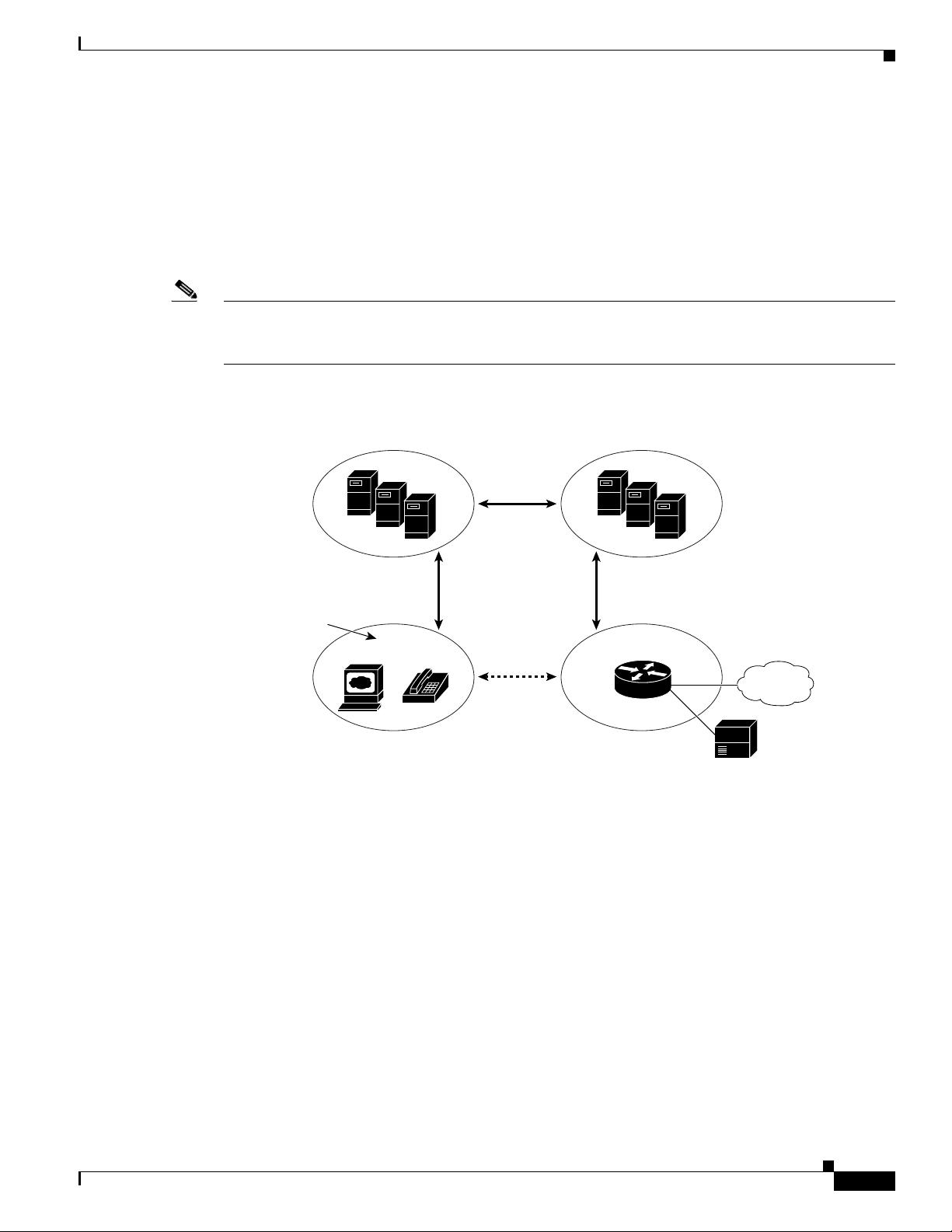
From an architectural standpoint, t
he physical components of a SIP network can also be grouped into
two categories—Clients and servers. Figure 1-2 illustrates the architecture of a SIP network.
Note SIP servers can interact with other application services, such as Lightweight Directory Access Protocol
(LDAP) servers, a database application, or an extensible markup language (XML) application. These
application services provide back-end services such as directory, authentication, and billable services.
Figure 1-2 SIP Architecture
SIP Clients
SIP Servers
OL-31821-01
SIP clients include:
• Gateways—Provide call control. Gateways provide many services, the most common being a
translation function between SIP conferencing endpoints and other terminal types. This function
includes translation between transmission formats and between communications procedures. In
addition, the gateway also translates between audio and video codecs and performs call setup and
clearing on both the LAN side and the switched-circuit network side.
• Phones—Can act as either a UAS or UAC. The ATA 190 can initiate SIP requests and respond to
requests.
SIP servers include:
Cisco ATA 190 Analog Telephone Adaptor Administration Guide for SIP (Version 1.0)
1-3
Page 14

Hardware Overview
• Proxy server—The proxy server is an intermediate device that receives SIP requests from a client
and then forwards the requests on the client’s behalf. Proxy servers receive SIP messages and
forward them to the next SIP server in the network. Proxy servers can provide functions such as
authentication, authorization, network access control, routing, reliable request retransmission, and
security.
• Redirect server—Receives SIP requests, strips out the address in the request, checks its address
tables for any other addresses that may be mapped to the address in the request, and then returns the
results of the address mapping to the client. Redirect servers provide the client with information
about the next hop or hops that a message should take, then the client contacts the next hop server
or UAS directly.
• Registrar server—Processes requests from UACs for registration of their current location. Registrar
servers are often co-located with a redirect or proxy server.
Hardware Overview
The ATA 190 is a compact, easy to install device. Figure 1-3 shows the rear panel of the ATA 190.
Chapter 1 Cisco ATA 190 Analog Telephone Adapter Overview
Figure 1-3 ATA 190—Rear View
390906
The unit provides these connectors and indicators:
• 5V power connector.
• Two RJ-11 FXS (Foreign Exchange Station) ports—The ATA 190 supports two independent RJ-11
phone ports that can connect to any standard analog phone device. Each port supports either voice
calls or fax sessions, and both ports can be used simultaneously.
• The ATA 190 has one network port—an RJ-45 10/100BASE-T data port to connect an
Ethernet-capable device, such as a computer, to the network.
Note The ATA 190 performs auto-negotiation for duplexity and speed and is capable of 10/100 Mbps,
full-duplex operation.
Software Features
The ATA 190 supports these protocols, services and methods:
• Secure Real-Time Transport Protocol, page 1-5
• Name Signaling Event based passthrough, page 1-5
• Transport Layer Security Protocol, page 1-5
• T.38 Fax Relay, page 1-5
Cisco ATA 190 Analog Telephone Adaptor Administration Guide for SIP (Version 1.0)
1-4
OL-31821-01
Page 15

Chapter 1 Cisco ATA 190 Analog Telephone Adapter Overview
• Voice Codecs Supported, page 1-5
• Other Supported Protocols, page 1-6
• ATA 190 SIP Services, page 1-6
• Modem Standards, page 1-7
• Fax Services, page 1-7
• Methods Supported, page 1-7
• Supplementary Services, page 1-8
Secure Real-Time Transport Protocol
SRTP (Secure Real-Time Transport Protocol) secures voice conversations on the network and provides
protection against replay attacks.
Note Currently ATA190 does not support secure conference call. A 2-way secure call is supported.
Software Features
Name Signaling Event based passthrough
Name Signaling Event (NSE)-based passthrough is simply the transport of fax or modem
communications using the G.711 codec.
The ATA 190 does not support NSE-based modem passthrough.
Transport Layer Security Protocol
Transport Layer Security (TLS) is a cryptographic protocol that secures data communications such as
e-mail on the Internet. TLS is functionally equivalent to Secure Sockets Layer (SSL).
T.38 Fax Relay
The T.38 fax relay feature enables devices to use fax machines to send files over the IP network. In
general, when a fax is received, it is converted to an image, sent to the T.38 fax device, and converted
back to an analog fax signal. T.38 fax relays configured with voice gateways decode or demodulate the
fax signals before they are transported over IP. With the SIP call control protocol, the T.38 fax relay is
indicated by Security Description (SDP) entries in the initial SIP INVITE message. After the initial SIP
INVITE message, the call is established to switch from voice mode to T.38 mode. Cisco Unified
Communications Administration allows you to configure a SIP profile that supports T.38 fax
communication.
Voice Codecs Supported
The ATA 190 supports these voice codecs (check your other network devices for the codecs they
support):
OL-31821-01
Cisco ATA 190 Analog Telephone Adaptor Administration Guide for SIP (Version 1.0)
1-5
Page 16

Software Features
• G.711µ-law
• G.711A-law
• G.729A
• G.729AB
Other Supported Protocols
The ATA 190 supports these additional protocols:
• 802.1Q VLAN tagging
• Cisco Discovery Protocol (CDP)
• Domain Name System (DNS)
• Dynamic Host Configuration Protocol (DHCP)
• Internet Control Message Protocol (ICMP)
• Internet Protocol (IP)
• Real-Time Transport Protocol (RTP)
Chapter 1 Cisco ATA 190 Analog Telephone Adapter Overview
• Transmission Control Protocol (TCP)
• Trivial File Transfer Protocol (TFTP)
• User Datagram Protocol (UDP)
ATA 190 SIP Services
These services include these features:
• IP address assignment—DHCP-provided or statically configured
• ATA 190 configuration by Cisco Unified Communications Manager configuration interface
• VLAN configuration
• Cisco Discovery Protocol (CDP)
• Low-bit-rate codec selection
• User authentication
• Configurable tones (dial tone, busy tone, alert tone, reorder tone, call waiting tone)
• Dial plans
• SIP proxy server redundancy
• Privacy features
• User-configurable, call waiting, permanent default setting
1-6
• Comfort noise during silent period when using G.711u/a and G.729ab
• Advanced audio mode
• Caller ID format
• Ring cadence format
• Silence suppression
Cisco ATA 190 Analog Telephone Adaptor Administration Guide for SIP (Version 1.0)
OL-31821-01
Page 17

Chapter 1 Cisco ATA 190 Analog Telephone Adapter Overview
• Hookflash detection timing configuration
• Configurable onhook delay
• Type of Service (ToS) configuration for audio and signaling ethernet packets
• Debugging and diagnostic tools
Modem Standards
The ATA 190 supports the following modem standards:
• V. 9 0
• V. 9 2
• V. 4 4
• K56Flex
• ITU-T V.34 Annex 12
• ITU-T V.34
• V.32bis
Software Features
Fax Services
Note Success of fax transmission depends on network conditions and fax modem response to these conditions.
• V. 3 2
• V. 2 1
• V. 2 2
• V. 2 3
The ATA 190 supports two modes of fax services, in which fax signals are transmitted using the G.711
codec:
• Fax pass-through mode—Receiver-side Called Station Identification (CED) tone detection with
automatic G.711A-law or G.711µ-law switching.
• T.38 Fax Relay mode: The T.38 fax relay feature enables devices to use fax machines to send files
over the IP network. In general, when a fax is received, it is converted to an image, sent to the T.38
fax device, and converted back to an analog fax signal. T.38 fax relays configured with voice
gateways decode or demodulate the fax signals before they are transported over IP.
The network must have reasonably low network jitter, network delay, and packet loss rate.
Methods Supported
The ATA 190 supports these methods. For more information, see RFC3261 (SIP: Session Initiation
Protocol).
• REGISTER
OL-31821-01
Cisco ATA 190 Analog Telephone Adaptor Administration Guide for SIP (Version 1.0)
1-7
Page 18

Installation and Configuration Overview
• REFER
• INVITE
• BYE
• CANCEL
• NOTIFY
• OPTIONS
• ACK
• SUBSCRIBE
Supplementary Services
SIP supplementary services are services that you can use to enhance your phone service. For information
on how to use these services, see Chapter 6, “Using SIP Supplementary Services”.
The ATA 190 supports these SIP supplementary services:
• Caller ID
• Call-waiting caller ID
Chapter 1 Cisco ATA 190 Analog Telephone Adapter Overview
• Voice mail indication
• Making a conference call
• Call waiting
• Call forwarding
• Calling-line identification
• Unattended transfer (blind transfer)
• Attended transfer
• Shared Line
• SpeedDial
• Conference (MeetMe)
• Pick Up
• Redial
Installation and Configuration Overview
Table 1-1 provides the basic steps required to install and configure the ATA 190 to make it operational
in a typical SIP environment where a large number of ATA 190s must be deployed.
1-8
Cisco ATA 190 Analog Telephone Adaptor Administration Guide for SIP (Version 1.0)
OL-31821-01
Page 19

Chapter 1 Cisco ATA 190 Analog Telephone Adapter Overview
Ta b l e 1-1 Overview of the Steps Required to Install and Configure the ATA 190 and Make it
Operational
Action Reference
1. Plan the network and ATA 190 configuration.
2. Install the Ethernet connection.
3. Install and configure the other network devices.
4. Install the ATA 190 but do not power up the
ATA 190 yet.
5. Power up the ATA 190.
Installation and Configuration Overview
Installing the ATA 190, page 3-2
OL-31821-01
Cisco ATA 190 Analog Telephone Adaptor Administration Guide for SIP (Version 1.0)
1-9
Page 20

Installation and Configuration Overview
Chapter 1 Cisco ATA 190 Analog Telephone Adapter Overview
1-10
Cisco ATA 190 Analog Telephone Adaptor Administration Guide for SIP (Version 1.0)
OL-31821-01
Page 21

CHAPTER
2
Preparing to Install the ATA 190 on Your Network
The ATA 190 enables you to communicate using voice over a data network. To provide this capability,
the ATA 190 depends upon and interacts with several other key Cisco Unified IP Telephony and network
onents, including Cisco Unified Communications Manager, DNS and DHCP s
comp
servers, media resources, and so on.
This chapter focuses on the interactions be
DNS and DHCP servers, TFTP servers, and switches. It also describes options for powering the
ATA 190.
For related information about voice and IP communications, see this URL:
http://www.cisco.com/en/US/products/sw/voicesw/index.html
This chapter provides an overview of the interaction between the ATA 190 and other key components of
oice over IP (VoIP) network. It includes these topics:
the V
• Understanding Interactions with Other Cisco Unified IP Communications Products, page 2-1
• Providing Power to the ATA 190, page 2-2
• Understanding Phone Configuration Files, page 2-3
• Understanding the ATA 190 Startup Process, page 2-4
tween the ATA 190, Cisco Unified Communications Manager,
ervers, TFTP
• Adding the ATA 190 to the Cisco Unified Communications Manager Database, page 2-5
• Determining the MAC Address of an ATA 190, page 2-7
Understanding Interactions with Other Cisco
Unified IP Communications Products
To function in the IP telephony network, the ATA 190 must be connected to a networking device, such
as a Cisco Catalyst switch. You must also register the ATA 190 with a Cisco Unified Communications
nager system before sending and receiving calls.
Ma
This section includes information on U
Unified Communications Manager, page 2-2.
Cisco ATA 190 Analog Telephone Adaptor Administration Guide for SIP (Version 1.0)
OL-31821-01
nderstanding How the ATA 190 Interacts with Cisco
2-1
Page 22

Chapter 2 Preparing to Install the ATA 190 on Your Network
Providing Power to the ATA 190
Understanding How the ATA 190 Interacts with Cisco Unified Communications
Manager
Cisco Unified Communications Manager is an open and industry-standard call processing system.
Cisco Unified Communications Manager software sets up and tears down calls between phones
nected to the ATA 190, integrating traditional PBX functionality with the corporate IP network.
con
Cisco Unified Communications Manager manages the component
phones, the access gateways, and the resources necessary for features such as call conferencing and route
planning. Cisco Unified Communications Manager also provides:
• Firmware for devices
• Authentication and encryption (if configured for the telephony system)
• Configuration and CTL files via the TFTP service
• Phone registration
• Call preservation, so that a media session continues if signaling is lost between the primary
Communications Manager and a phone
For information about configuring Cisco Unified Communications Manager to work with the IP devices
scribed in this chapter, see Cisco Unified Communications Manager Administration Guide, Cisco
de
nified Communications Manager System Guide, and Cisco Unified Communications Manager Security
U
Guide.
s of the IP telephony system—the
Providing Power to the ATA 190
The ATA 190 is powered with external power. External power is provided through a separate power
supply.
The following sections provide more information about powering a ATA 190:
• Power Guidelines, page 2-2
• Power Outage, page 2-2
• Understanding Phone Configuration Files, page 2-3
Power Guidelines
The following power type and guideline applies to external power for the ATA 190:
• Power Type—External power (Provided through the Universal AC external power supply.)
• Guidelines—The ATA 190 uses the Universal AC power supply 110/240V
Power Outage
Your accessibility to emergency service through the phone is dependent on the phone being powered. If
there is an interruption in the power supply, Service and Emergency Calling Service dialing will not
function until power is restored. In the case of a power failure or disruption, you may need to reset or
reconfigure equipment before using the Service or Emergency Calling Service dialing.
2-2
Cisco ATA 190 Analog Telephone Adaptor Administration Guide for SIP (Version 1.0)
OL-31821-01
Page 23

Chapter 2 Preparing to Install the ATA 190 on Your Network
Understanding Phone Configuration Files
Configuration files for a phone are stored on the TFTP server and define parameters for connecting to
Cisco Unified Communications Manager. In general, any time you make a change in Cisco
ied Communications Manager that requires the phone to be reset, a ch
Unif
to the phone’s configuration file. If the system needs to reset or restart, both ports must reset or restart
at the same time.
Configuration files also contain information about which imag
image load differs from the one that is currently loaded on a phone, the phone contacts the TFTP server
to request the required load files. (These files are digitally signed to ensure the authenticity of the file
source.)
In addition, if the device security mode in the configurat
on the phone has a valid certificate for Cisco Unified Communications Manager, th
a TLS connection to Cisco Unified Communications Manager. Otherwi
TCP/UDP connection. For SIP phones, a TLS connection requires that the transport protocol in the
phone configuration file be set to TLS, which corresponds to the transport type in the SIP Security
Profile in Cisco Unified Communications Manager.
ion file is set to Authenticated and the CTL file
Understanding Phone Configuration Files
ange is automatically made
e load the phone should be running. If this
e phone establishes
se, the phone establishes a
If you configure security-related settings in Cisco Unif
ied Communications Manager Administration,
the phone configuration file will contain sensitive information. To ensure the privacy of a configuration
file, you must configure it for encryption. For detailed information, see Configuring Encrypted Phone
Configuration Files in Ci
A phone accesses a default configuratio
sco Unified Communications Manager Security Guide.
n file named XMLDefault.cnf.xml only when the phone has not
received a valid Trust List file containing a certificate assigned to the Cisco Unified Communications
Manager and TFTP.
If auto registration is not enabled and you did not add the phone to the Cisco Unified Communications
ager database, the phone does not attempt to register with Cisco Unified Communications Manager.
Man
If the phone has registered before, the phone accesses th
e configuration file named
ATA <mac_address>.cnf.xml, where mac_address is the MAC address of the phone.
• Configuration Files:
–
For unsigned and unencrypted files—ATA<mac>.cnf.xml
–
For signed files—ATA<mac>.cnf.xml.sgn
–
For signed and encrypted files—ATA<mac>.cnf.xml.enc.sgn
• Dial Plan—<dialplan>.xml
–
Support “,” for second dial tone
–
No support > for configuring termination key
–
No support + dial pattern which contains + will be ignored
–
Maximum number of dial pattern is 10
OL-31821-01
–
Maximum length of each dial pattern is 30
The filenames are derived from the MAC Address and Description fields in the Phone Configuration
indow of Cisco Unified Communications Manager Administration. The MAC address uniquely
w
entifies the phone. For more information see the Cisco Unified Communications Manager
id
Administration Guide.
Cisco ATA 190 Analog Telephone Adaptor Administration Guide for SIP (Version 1.0)
2-3
Page 24

Chapter 2 Preparing to Install the ATA 190 on Your Network
Understanding the ATA 190 Startup Process
For more information about how the phone interacts with the TFTP server, see the Cisco Unified
Communications Manager System Guide, Cisco TFTP section.
Understanding the ATA 190 Startup Process
When connecting to the VoIP network, the ATA 190 goes through a standard startup process, as described
in Table 2-1. Depending on your specific network configuratio
on your ATA 190.
Ta b l e 2-1 ATA 190 Startup Process
Task Purpose Related Topics
1. Obtaining Power.
The ATA 190 uses external power.
2. Loading the Stored Image.
The ATA 190 has non-volatile flash memory in which it
tores firmware images and user-defined preferences. At
s
startup, the phone runs a bootstrap loader that loads a
phone image stored in flash memory. Using this image, the
phone initializes its software and hardware.
3. Obtaining an IP Address.
See Providing Power to the ATA 190, page 2-2.
n, not all of these process steps may occur
If the ATA 190 is using DHCP to obtain an IP address, the
vice queries the DHCP server to obtain one. If you are
de
not using DHCP in your network, you must assign static IP
addresses to each device locally.
4. Requesting the CTL file.
The TFTP server stores the CTL file. This file contains the
ificates necessary for establishing a secure connection
cert
between the device and Cisco Unified Communications
Manager
.
See the C
Security Guide, Configuring the Cisco CTL
Client.
isco Unified Communications Manager
2-4
Cisco ATA 190 Analog Telephone Adaptor Administration Guide for SIP (Version 1.0)
OL-31821-01
Page 25

Chapter 2 Preparing to Install the ATA 190 on Your Network
Adding the ATA 190 to the Cisco Unified Communications Manager Database
Table 2-1 ATA 190 Startup Process (continued)
Task Purpose Related Topics
5. Requesting the Configuration File.
The TFTP server has configuration files, which define
paramet
Communications Manager and other information for the
ATA 190.
6. Contacting Cisco Unified Communications Manager.
The configuration file defines how the ATA 190
co
Manager and
obtaining the file from the TFTP server, the device attempts
to make a connection to the highest priority Cisco
Unified Communications Manager on the list. If the
securi
signaling (encrypted or authenticated), and the Cisco
Unified Communications Manager is set to secure mode,
the device makes a TLS connection. Otherwise, it makes a
nonsecure TCP/UDP connection.
ers for connecting to Cisco Unified
mmunicates with Cisco Unified Communications
provides a device with its load ID. After
ty profile of the device is configured for secure
nderstanding Phone Configuration Files,
See U
page 2-3.
nderstanding Phone Configuration Files,
See U
page 2-3.
Adding the ATA 190 to the Cisco Unified Communications
Manager Database
Before installing the ATA 190, you must choose a method for adding the devices to the
Cisco Unified Communications Manager database. These sect
• Adding the ATA 190 with Auto-Registration, page 2-6
• Adding the ATA 190 with Cisco Unified Communications Manager Administration, page 2-6
Table 2-2
Cisco Unified Communications Manager database.
Ta b l e 2-2 Methods for Adding the ATA 190 to the Cisco Unified Communications Manager
Method
Auto-registration No
Using the Cisco Unified
ommunications
C
Manager Administration
provides an overview of these methods for adding the ATA 190 to the
Database
Requires MAC
Address? Notes
• Results in automatic assignment of directory
numbers.
• Not available when mixed mode is enabled.
Yes Requires phones to be added individually.
ions describe the methods:
OL-31821-01
Cisco ATA 190 Analog Telephone Adaptor Administration Guide for SIP (Version 1.0)
2-5
Page 26

Adding the ATA 190 to the Cisco Unified Communications Manager Database
Adding the ATA 190 with Auto-Registration
By enabling auto-registration before you begin installing the ATA 190, you can:
• Add devices without first gathering MAC addresses from the ATA 190.
• Automatically add a ATA 190 to the Cisco Unified Communications Manager database when you
physically connect the phone to your IP telephony network. During auto-registration, Cisco Unified
Commu
• Quickly enter devices into the Cisco Unified Communications Manager database and modify any
settings, such as the directory numbers, from Cisco Unified Communications Manager.
• Move auto-registered devices to new locations and assign them to different device pools without
affecting their directory numbers.
Auto-registration is disabled by default. In some cases, you
example, if you want to assign a specific directory number to the phone or if you plan to use secure
connection with Cisco Unified Communications Manager as described in Cisco Unified
Communications Manager Security Guide. For information about enabling auto-registration, see the
Enabling Auto-Registration in the Cisco Unified Communications Manager Administration Guide.
nications Manager assigns the next available sequential directory number to the phone.
Chapter 2 Preparing to Install the ATA 190 on Your Network
may not want to use auto-registration; for
Note When you configure the cluster for mixed mode through the Cisco CTL client, auto-registration is
automatically disabled. When you configure the cluster for nonsecure mode through the Cisco CTL
client, auto-registration is not automatically enabled.
Related Topics
Adding the ATA 190 with Cisco Unified Communications Manager Administration, page 2-6
Adding the ATA 190 with Cisco Unified Communications Manager
Administration
You can add the ATA 190 individually to the Cisco Unified Communications Manager database using
Cisco Unified Communications Manager Administration. To do so, you first need to obtain the MAC
s for each device.
addres
For information about determining a MAC address, see Determi
page 2-7.
After you have collected MAC addresses, in Cisco Unified Communications Manager Administration,
choose De
Note The first device used the MAC address and the second device uses the shifted MAC address (example,
AABBCCDDEEFF to BBCCDDEEFF01). You can add two devices from the Unified CM administration
page.
vice > Phone and click Add New to begin.
ning the MAC Address of an ATA 190,
2-6
For complete instructions and conceptual information about Cisco Unified Communications Manager,
see the Cisco Unified Communications Manager Administration Guide and the Cisco Un
Communications Manager System Guide.
Cisco ATA 190 Analog Telephone Adaptor Administration Guide for SIP (Version 1.0)
ified
OL-31821-01
Page 27

Chapter 2 Preparing to Install the ATA 190 on Your Network
Determining the MAC Address of an ATA 190
Related Topics
Adding the ATA 190 with Auto-Registration, page 2-6
Determining the MAC Address of an ATA 190
Several of the procedures that are described in this manual require you to determine the MAC address
of an ATA 190. You can determine the MAC address for a device in any of these ways:
• Look at the MAC label on the back of the device.
• Display the web page for the device and click the Device Information hyperlink.
OL-31821-01
Cisco ATA 190 Analog Telephone Adaptor Administration Guide for SIP (Version 1.0)
2-7
Page 28

Determining the MAC Address of an ATA 190
Chapter 2 Preparing to Install the ATA 190 on Your Network
2-8
Cisco ATA 190 Analog Telephone Adaptor Administration Guide for SIP (Version 1.0)
OL-31821-01
Page 29

Installing the ATA 190
This section describes how to connect the ATA 190 hardware and configure the ATA 190 by loading the
QED and firmware files. You must install the QED file first and then install the firmware file.
Cisco ATA Rear Panel Connections
Figure 3-1 Cisco ATA Rear Panel
CHAPTER
3
PHONE 1/PHONE 2—Connection to Analog telephones or fax.
NETWORK—Co
POWER—Co
nnection to IP network.
nnection to 5V power adapter.
Network Requirements
The ATA 190 acts as an endpoint on an IP telephony network. The following equipment is required:
• Call Control system
• Voice packet gateway—Required if you are connecting to the Public Switched Telephone Network
(PSTN). A gateway is not required if an analog key system is in effect.
• Ethernet connection
Safety Recommendations
To ensure general safety, follow these guidelines:
• Do not get this product wet or pour liquids into this device.
390906
OL-31821-01
Cisco ATA 190 Analog Telephone Adaptor Administration Guide for SIP (Version 1.0)
3-1
Page 30

What the ATA 190 Package Includes
• Do not open or disassemble this product.
• Do not perform any action that creates a potential hazard to people or makes the equipment unsafe.
• Use only the power supply that comes with the ATA 190.
Chapter 3 Installing the ATA 190
Warning
Warning
Warning
Warning
Ultimate disposal of this product should be handled according to all national laws and regulations.
Read the installation instructions before you connect the system to its power source.
The plug-socket combination must be accessible at all times because it serves as the main
disconnecting device.
Do not work on the system or connect or disconnect cables during periods of lightning activity.
For translated warnings, see the Regulatory Compliance and Safety Information for the Cisco ATA 190
manual.
What the ATA 190 Package Includes
The ATA 190 package contains the following items:
• ATA190 device
• Pointer Card
• 5V Power Adapter with appropriate Country Clip
• Ethernet Cable
Note The ATA 190 is intended for use only with the 5V DC power adapter that comes with the unit.
Installing the ATA 190
To install an ATA 190, follow these steps:
Procedure
Step 1 Connect the power supply to the Cisco DC Adapter port.
Step 2 Connect a straight-through Ethernet cable from the network to the 10/100 SW port on the ATA 190. Each
ATA 190 ships with one Ethernet cable in the box.
Cisco ATA 190 Analog Telephone Adaptor Administration Guide for SIP (Version 1.0)
3-2
OL-31821-01
Page 31

Chapter 3 Installing the ATA 190
Note You can use either Category 3/5/5e/6 cabling for 10 Mbps connections, but you must use Category 5/5e/6
for 100 Mbps connections.
Attaching a Phone to the ATA 190
You can attach one or two phones to an ATA 190 by connecting them to a line port of the ATA 190 with
a RJ11 cable. The line LED will blink when there is activity on that line.
Verifying the ATA 190 Startup Process
After the ATA 190 has power connected to it, the phone begins its startup process by cycling through
these steps:
1. The Power LED is on.
2. The Network LED is flashing (when there is data traffic on Network port connected to a WAN port.)
The ATA 190 is launching its application.
Attaching a Phone to the ATA 190
3. Network LED is on.
4. After the Phone1 and Phone2 resgister with CUCM successfully, the corresponding LEDs are on.
5. All of the LEDs are on.
If the ATA 190 flash memory is erased
it can restore the image by manual upgrading.
When you go offhook on the phone, you will see the line LED to begin flashing, and you will hear dial
one. The ATA 190 has completed the startup process.
t
or the load is corrupted, the ATA enters a recovery mode where
Configuring Startup Network Settings
It is recommended to use DHCP instead of Static IP. DHCP server provides ip, mask, gateway, tftp
server, etc.
Configuring Security on the ATA 190
The security features protect against several threats, including threats to the identity of the phone and to
data. These features establish and maintain authenticated communication streams between the phone and
the Cisco Unified Communications Manager server, and digitally sign files before they are delivered.
For more information about the sec
Security Guide.
urity features, see the Cisco Unified Communications Manager
OL-31821-01
You can initiate the installation of a Locally Signi
Configuration menu on the phone. This menu also lets you update or remove an LSC.
Before you begin, make sure that the appropriate Cisco Unified Communications Manager and the CAPF
urity configurations are complete:
sec
Cisco ATA 190 Analog Telephone Adaptor Administration Guide for SIP (Version 1.0)
ficant Certificate (LSC) from the Security
3-3
Page 32

Configuring Security on the ATA 190
• On Cisco Unified Communications Operating System Administration, verify that the CAPF
certificate has been installed
• The CAPF is running and configured
Chapter 3 Installing the ATA 190
See the Cisco Un
Note If you want to update LSC, you need to use reset to factory default from Chapter B, “Voice Menu
ified Communications Manager Security Guide for more information.
Codes”.
3-4
Cisco ATA 190 Analog Telephone Adaptor Administration Guide for SIP (Version 1.0)
OL-31821-01
Page 33

CHAPTER
4
Configuring the ATA 190
Yo u m us t u se C is co Unified Communications Manager Administration to configure telephony features
and assign users.
This chapter provides an overview of these configuration and setup procedures. Cisco Unified
Commu
Telephony Features Available for the ATA 190
Table 4-1 lists the supported telephony features, many of which you configure by using
Cisco Unified Communications Manager Administration.
Ta b l e 4-1 Telephony Features for the ATA 190
Feature Description Configuration Reference
Audible Message
aiting Indicator
W
cBarge Allows a user to join a non-pri
A stutter tone from the handset, headset, or speakerphone
indicates that a user has one or more new voice messages on
a line.
Note The stutter tone is line-specific. You hear it only
line. cBarge adds a user to a call and converts it into a
conference, allowing the user and other parties to access
conference features.
The phones support Barge on a shared confere
nications Manager documentation provides detailed instructions for these procedures.
For more information, refer to:
• Cisco Unified Communications
Manager Administration Guide,
Message Waiting Configuration.
when using the line with the waiting messages.
vate call on a shared phone
nce bridge.
• Cisco Unified Communications
Manager System Guide, Voice Mail
Connectivity to Cisco Unified
Communications Manager.
For more information, refer to:
• Cisco Unified Communications
Manager Administration Guide,
Cisco Unified IP Phone
Configuration.
• Cisco Unified Communications
Manager System Guide, Cisco
Unified IP Phones.
OL-31821-01
• Cisco Unified Communications
Manager Features and Services
Guide, Barge and Privacy.
Cisco ATA 190 Analog Telephone Adaptor Administration Guide for SIP (Version 1.0)
4-1
Page 34

Chapter 4 Configuring the ATA 190
Telephony Features Available for the ATA 190
Table 4-1 Telephony Features for the ATA 190 (continued)
Feature Description Configuration Reference
Call forward Allows users to redirect incoming calls to another number.
Call forward options include Call Forward All, Call
Forward Busy, and Call Forward No Answer.
For more information, refer to:
• Cisco Unified Communications
Manager Administration Guide,
Directory Number Configuration.
• Cisco Unified Communications
Manager System Guide, Cisco
Unified IP Phones.
Call pickup Allows users to redirect a call that is ringing on another
one within their pickup group to their phone.
ph
You can configure an audio and/or visual alert for the
mary line on the phone. This alert notifies the users that
pri
For more information, refer to the Cisco
fied Communications Manager
Uni
Features and Services Guide, Call
Pickup.
a call is ringing in their pickup group.
Call waiting Indicates (and allows users to
answer) an incoming call that
rings while on another call. Displays incoming call
information on the phone screen.
Caller ID Displays caller identification such as a phone number,
name, or o
ther descriptive text on the phone screen.
For more information, refer to the Cisco
Unified Communications System Guide,
Understanding Directory Numbers.
For more information, refer to:
• Cisco Unified Communications
Manager Administration Guide,
Cisco Unified IP Phone
Configurations.
• Cisco Unified Communications
Manager System Guide,
Understanding Route Plans.
• Cisco Unified Communications
Manager Features and Services
Guide, Call Display Restrictions.
Conference
4-2
• Allows a user to talk simultaneously with multiple
parties by calling each participant individually.
Conference features include Adhoc Conference,
cBarge, and Meet–Me.
• Allows a non-initiator in a standard (ad hoc) conference
to add or remove participants.
Cisco ATA 190 Analog Telephone Adaptor Administration Guide for SIP (Version 1.0)
• Cisco Unified Communications
Manager Administration Guide,
Directory Number Configuration.
For more information, refer to:
• Cisco Unified Communications
Manager System Guide,
Cisco Unified IP Phones.
• The service parameter, Advance
Adhoc Conference, (disabled by
default in Cisco Unified
Communications Manager
Administration) allows you to
enable these features.
Note Be sure to inform your users
whether these features are
activated.
OL-31821-01
Page 35

Chapter 4 Configuring the ATA 190
Telephony Features Available for the ATA 190
Table 4-1 Telephony Features for the ATA 190 (continued)
Feature Description Configuration Reference
Direct transfer Allows users to connect two calls to each other (without
remaining on the line).
For more information, refer to the Cisco
Unified Communications Manager
System Guide, Cisco Unified IP Phones.
Forced authorization
codes (F
AC)
Controls the types of calls that certain users can place.
Note If you are using this feature, you must disable
Enbloc dialing.
For more information, refer to the Cisco
U
nified Communications Manager
eatures and Services Guide, Client
F
Matter Codes and Forced Authorization
Codes.
Group call pickup Allows a user to answer a call that is ringing on a directory
mber in another group.
nu
For more information, refer to the Cisco
Unified Communications Manager
Features and Services Guide, Call
Pickup.
Hold/Resume Allows the user to move a connec
state and a held state.
Note No support for resuming a call from a shared line
party.
Meet–Me
onference
c
Allows a user to host a Meet-Me conference in which other
participants call a predetermined number at a scheduled
time.
ted call between an active
For more information, refer to:
Requires no configuration, unless you
ant to use music on hold. See Music on
w
hold in this table for information.
For more information refer to Cisco
Unified Communications Manager
Administration Guide, Meet-Me
Number/Pattern Configuration.
Message Waiting Defines directory numbers for message-waiting on and
message-w
aiting off indicator. A directly connected
voice-messaging system uses the specified directory
number to set or to clear a message-waiting indication for a
particular Cisco Unified IP Phone.
For more information refer to:
• Cisco Unified Communications
Manager Administration Guide,
Message Waiting Configuration.
• Cisco Unified Communications
Manager System Guide, Voi c e M ai l
Connectivity to Cisco Unified
Communications Manager.
Music on hold Plays music while cal
lers are on hold. For more information refer to Cisco
Unified Communications Manager
Features and Services Guide, Music On
Hold.
Privacy Prevents users who share a line from adding themselves to
call and from viewing information on their phone screens
a
about the call of the other user.
For more information refer to:
• Cisco Unified Communications
Manager Administration Guide,
Cisco Unified IP Phone
Configuration.
• Cisco Unified Communications
Manager System Guide, Cisco
Unified IP Phones.
OL-31821-01
• Cisco Unified Communications
Manager Features and Services
Guide Barge and Privacy.
Cisco ATA 190 Analog Telephone Adaptor Administration Guide for SIP (Version 1.0)
4-3
Page 36

Chapter 4 Configuring the ATA 190
Configuring Product Specific Configuration Parameters
Table 4-1 Telephony Features for the ATA 190 (continued)
Feature Description Configuration Reference
Redial Allows users to call the most recently dialed phone number
y pressing feature code *#.
b
Shared line Allows a user to have several phones that share the same
ph
one number or allows a user to share a phone number with
a coworker.
Speed dialing Allows users to speed dial a phone number by entering an
gned index code (1 to 199) on the phone keypad.
assi
Note You can use Speed Dialing while on-hook or
off-hook.
Users assign index codes from the User Options web pages.
Time Zone Update Updates the IP phone with time zone changes. For more information, refer to the Cisco
Voice-messaging
system
Enables callers to leave messages if calls are unanswered. For more information refer to:
Requires no configuration.
For more information refer to the Cisco
Unified Communications Manager
System Guide, Understanding Directory
Numbers.
For more information, refer to:
• Cisco Unified Communications
Manager Administration Guide,
Cisco Unified IP Phone
Configuration.
• Cisco Unified Communications
Manager System Guide, Cisco
Unified IP Phones.
fied Communications Manager
Uni
Administration Guide, Date/Time Group
Configuration.
• Cisco Unified Communications
Manager Administration Guide,
Cisco Voice-Mail Port
Configuration.
• Cisco Unified Communications
Manager System Guide, Voi c e M ai l
Connectivity to Cisco
Unified Communications Manager.
Configuring Product Specific Configuration Parameters
Cisco Unified Communications Manager Administration allows you to set some product specific
configuration parameters for the ATA 190. Table 4-2 lists the configuration windows and their paths to
configure the parameters.
Ta b l e 4-2 Configuration Information
Configuration Window Path
Enterprise Phone
nfiguration window
Co
Common Phone Profile
wi
ndow
Phone Configuration window Device > Phone;
System > Enterprise Phone Configuration
Device > Device Settings > Common Phone Profile
Product Specific Configuration portion of window
4-4
Cisco ATA 190 Analog Telephone Adaptor Administration Guide for SIP (Version 1.0)
OL-31821-01
Page 37

Chapter 4 Configuring the ATA 190
Table 4-3 lists the configuration parameters you can set using Cisco Unified Communications Manager
Administration.You can set the configu
listed in Table 4-2.
When you set the parameters, select the
to update. If you do not check this box, the corresponding parameter setting does not take effect.
Note Some ATA 190 parameters are set from port 1 only. Setting the parameters from port 2 will have no
effect. Set the following parameters from port 1 only—IVR Password, Phone Load Name, CDP, and Web
Access.
Ta b l e 4-3 Configuration Parameters for the ATA 190
Parameter Description
Auto Barge Auto Barge adds a user to an active call. An offhook phone
Call Sequence
Configuring Product Specific Configuration Parameters
ration parameters using any of the three configuration windows
Override Common Settings check box for each setting you wish
automatic
ally adds the user (initiator) to the shared line call
(target), and the users currently on the call receive a tone (if
configured). Barge supports built-in conference and shared
conference bridges.
The Auto Barge feature allows the user to go offhook and be
d to the call. The Auto Barge feature supports built-in
adde
conferences and shared conference bridges.
• Bellcore FSK
• ETSI FSK
Caller ID
• BT FSK
• Bellcore FSK
• ETSI FSK
Cisco Discovery Protocol (CDP) Enable or disable the CDP function of the ATA 190
Fax Error Correction Mode Override You can set the fax error correction mode override values to
ne of the following settings:
o
• Default
• On
• Off
Fax Mode The Cisco ATA supports two fax modes:
• Fax Pass–Through—Allows fax and modem traffic to
pass through a voice port
• T.38 Fax Relay—Allows for a more robust protocol for
fax transmission over packet networks
• NSE Fax pass–Through—g711ulaw
• NSE Fax pass–Through—g711alaw
Hookflash Timer
(100 ms to 1500 ms)
Hookflash Timer
The time to validate hookflash event.
Impedance The ATA 190 provides multiple impedance values, such as
0 ohm for use in the United States
60
OL-31821-01
Cisco ATA 190 Analog Telephone Adaptor Administration Guide for SIP (Version 1.0)
4-5
Page 38

Adding Users to Cisco Unified Communications Manager
Table 4-3 Configuration Parameters for the ATA 190 (continued)
Parameter Description
Input Audio Level Gain value of Network–to–Phone
IVR Password ATA 190 IVR password
Offhook Validation Timer
Chapter 4 Configuring the ATA 190
Offhook Validation Timer
(50 ms to 1000 ms)
Onhook Delay Timer
(0 s to 155 s)
Onhook Validation Timer Onhook Validation Timer
Output Audio Level Gain value of Phone–to–Network
Indicates the time to validate an offhook event
On-hook Delay Timer
Indicates the time to delay an onhook event
Note This parameter is reserved but does take effect now.
Indicates time to validate an onhook event
Adding Users to Cisco Unified Communications Manager
Adding users to Cisco Unified Communications Manager allows you to display and maintain
information about users and allows each user to perform these tasks:
• Access the corporate directory and other customized directories from an ATA 190.
• Create a personal directory.
• Set up speed dial and call forwarding numbers.
• Subscribe to services that are accessible from an ATA 190.
You can add users to Cisco Unified Communications Manager using either of these methods:
• To add users individually, choose User Management > End User from
Cisco Unified Communications Manager Administration.
4-6
Refer to C
adding users. Refer to Cisco Unified Communications Manager System Guide for details about user
information.
Cisco ATA 190 Analog Telephone Adaptor Administration Guide for SIP (Version 1.0)
isco Unified Communications Manager Administration Guide for more information about
OL-31821-01
Page 39

Configuring Fax Services
The ATA 190 provides two modes of fax services that are capable of internetworking with Cisco IOS
gateways over IP networks. These modes are called fax pass-through mode and T.38 fax relay mode.
With fa
it through the Voice Over IP (VoIP) network as though the fax were a voice call.
With T
standard fax terminals communicating over SIP networks. T.38 fax relay mode provides a more reliable
and error-free method of sending faxes over an IP network
Using Fax Mode
You can choose the preferred fax mode on the phone configuration page of the Unified CM
administration page. From the fax mode pull-down window, choose one of the following modes:
• Fax pass-through
• T.38 fax r e lay
x pass-through mode, the ATA 190 encodes fax traffic within the G.711 voice codec and passes
.38 fax relay mode, the ATA 190 supports the transmission of faxes, in real time, between two
CHAPTER
5
• NSE Fax pass–Through—g711ulaw
• NSE Fax pass–Through—g711alaw
You can set the Fax Error correction mode override values. From the fax mode pull-down window,
ose one of the following modes:
cho
• On
• Off
• Default
Fax Modem Standards
Note V.34 is supported for fax.
The ATA 190 supports the following fax modem standards:
• ITU-T V.34
• ITU-T V.34 Annex 12
OL-31821-01
Cisco ATA 190 Analog Telephone Adaptor Administration Guide for SIP (Version 1.0)
5-1
Page 40

Using Fax Mode
• K56flex
• V. 2 1
• V. 2 2
• V. 2 3
• V. 3 2
• V.32bis
• V. 4 4
• V. 9 0
• V. 9 2
Fax Modem Speeds
The ATA 190 supports the following fax modem speeds:
• 14.4 kb/s
• 12 kb/s
Chapter 5 Configuring Fax Services
• 9.6 kb/s
• 7.2 kb/s
• 4.8 kb/s
• 2.4 kb/s
5-2
Cisco ATA 190 Analog Telephone Adaptor Administration Guide for SIP (Version 1.0)
OL-31821-01
Page 41

Using SIP Supplementary Services
SIP supplementary services are services that you can use to en hance your telephone service. These
services include call forward, redial, call forwarding, and conference calling.
Common Supplementary Services
The supplementary services described in this section, and their configuration and implementation,
depend on the system of the country in which the service is activated. For information about your
country’s implementation of services, contact your local Cisco equipment provider.
This section contains the fo
• Attended Transfer, page 6-2
• Call Pickup, page 6-2
• Caller ID, page 6-2
llowing topics:
CHAPTER
6
• Call-Waiting Caller ID, page 6-2
• Call Hold, page 6-2
• Group Call Pickup, page 6-3
• Meet–Me Conference, page 6-3
• Privacy, page 6-3
• Shared Line, page 6-3
• Speed Dial, page 6-4
• Redial, page 6-4
• Unattended Transfer, page 6-4
• Voice Mail Indication, page 6-5
• Voice-Messaging System, page 6-5
• Making a Conference Call in the United States, page 6-5
• Making a Conference Call in Sweden, page 6-5
• Call Waiting in the United States, page 6-6
• Call Waiting in Sweden, page 6-6
• About Call Forwarding, page 6-6
• Call Forwarding in the United States, page 6-6
OL-31821-01
Cisco ATA 190 Analog Telephone Adaptor Administration Guide for SIP (Version 1.0)
6-1
Page 42

Common Supplementary Services
• Call Forwarding in Sweden, page 6-6
Attended Transfer
This feature allows a user to tr ansfer an exist ing ca ll to anot her phone number after first consultin g with
the dialed party before the user hangs up. Perform the following steps to complete an attended transfer:
Procedure
Step 1 Press the flash button on the phone handset to put the existing party on hold and get a dial tone.
Step 2 Dial the phone number to which the existing party is being transferred.
Step 3 When the callee answers the phone, you ma y c o n su l t w i t h t h e c a l le e and then transfer the existing party
by hanging up your phone handset.
Chapter 6 Using SIP Supplementary Services
Call Pickup
Allows you to answer a call that is ringing on an oth er ph one withi n your call pickup grou p. Perform th e
following steps to use the call pickup feature:
Procedure
Step 1 Pick up the phone handset.
Step 2 Press **3.
Caller ID
When the phone rings, the ATA 190 sends a Caller ID signal to the phone between the first and second
ring (with name, phone number, time, and date information, if these are available).
Call-Waiting Caller ID
The A TA 190 plays a call waiting tone, then sends an off-hook Caller ID signal to the phone immediately
after the first tone burst.
The ATA 190 sends the name, phone number, time, and date information, if these are available.
Call Hold
Cisco ATA 190 Analog Telephone Adaptor Administration Guide for SIP (Version 1.0)
6-2
This feature allows the user to place an active state in a held state.
OL-31821-01
Page 43

Chapter 6 Using SIP Supplementary Services
Group Call Pickup
Allows you to answer a call on a phone that is outside your call pickup group by:
• Using a group pickup number
• Dialing the ringing phone's number
Perform the following steps to use the group call pickup feature:
Procedure
Step 1 Pick up the phone handset.
Step 2 Press **4 > group ID > #.
Meet–Me Conference
Common Supplementary Services
Privacy
This feature allows a user to host a Meet–Me conference in which other participants call a predetermined
number at a scheduled time. Perform the following steps to complete a meet–me conference:
Procedure
Step 1 Pick up the phone handset.
Step 2 Press **5 > roo m ID > #.
This feature prevents users who share a line from adding themselves to a call and from viewing
information on their phone screens about the call of the other user. Perform the following steps to enable
or disable the privacy feature:
Procedure
Step 1 Pick up the phone handset.
Step 2 During an active call, press **8 to enable the privacy feature.
Step 3 During an active call, press **9 to disable the privacy feature.
Shared Line
OL-31821-01
This feature allows a user to have multiple phones that share the same phone number or allows a user to
share a phone number with a coworker. It enables the phone lines to barge into an existing call.
—If auto barge is enabled, off hook triggers C-barge.
Cisco ATA 190 Analog Telephone Adaptor Administration Guide for SIP (Version 1.0)
6-3
Page 44

Common Supplementary Services
—If auto barge is disabled, pressing “**6” triggers C-barge.
Speed Dial
This feature allows users to speed dial a phone number by entering an assigned index code (1 to 199) on
the phone keypad.
Redial
Allows users to call the most recently dialed phone number by pressing the *# buttons.
Unattended Transfer
This feature allows a user to transfer an existing call to another phone number without waiting for the
dialed party to answer before the user hangs up. Two methods exist for performing an unattended
transfer:
Chapter 6 Using SIP Supplementary Services
• Semi-unattended Transfer, page 6-4
• Fully Unattended Transfer (Blind Transfer), page 6-4
Semi-unattended Transfer
Perform the following steps to complete a semi-unattended transfer:
Procedure
Step 1 Press the flash button on the phone handset to put the other party on hold and get a dial tone.
Step 2 Dial the phone number to which you would like to transfer the other party.
Step 3 Wait for at least one ring and then ha ng up your phone to tran sfer the other part y.
Fully Unattended Transfer (Blind Transfer)
Perform the following steps to complete a fully unattended transfer:
Procedure
Step 1 Press the flash button on the phone handset to put the other party on hold and get a dial tone.
Step 2 Press #90 (the transfer service activation code) on your phone keypad, then enter the phone number to
which you want to transfer the other pa rty, then press #.
Step 3 Hang up your phone.
6-4
Cisco ATA 190 Analog Telephone Adaptor Administration Guide for SIP (Version 1.0)
OL-31821-01
Page 45

Chapter 6 Using SIP Supplementary Services
Voice Mail Indication
This feature allows the ATA 190 to play an intermitt ent d ial tone if there is a message in the u ser's voice
mail box.
Voice-Messaging System
This feature enables callers to leave messages if calls are unanswered or access voice messages. Perform
the following steps to access the voice-messaging system:
Procedure
Step 1 Pick up the phone handset.
Step 2 Press *0.
Common Supplementary Services
Making a Conference Call in the United States
Procedure
Step 1 Dial the first number.
Step 2 When the person you called answers, press the flash or receiver button on the phone handset. This will
put the first person you called on hold and you will receive a dial tone.
Step 3 Dial the second person and speak normally when that person answers.
Step 4 To conference with both callers at the same time, perform a hook flash.
Making a Conference Call in Sweden
Procedure
Step 1 Dial the first number.
Step 2 When the person you called answers, press the flash or receiver button on the phone handset. This will
put the first person you called on hold and a dial tone will sound.
Step 3 Dial the second person and speak normally when that person answers.
Step 4 Perform a hook flash, then press 2 on your phone keypad to return to the first person. You can continue
to switch back and forth between the two callers.
OL-31821-01
Step 5 To conference with both callers at the same time, perform a hook flash, t hen press 3 on the phone keypad.
Once you conference all three callers, the only way to drop a caller is for that caller to hang up.
Cisco ATA 190 Analog Telephone Adaptor Administration Guide for SIP (Version 1.0)
6-5
Page 46

Common Supplementary Services
Call Waiting in the United States
If someone calls you while you are speaking on the phone, you can answer by performing a hook flash
but cannot conference in all three callers.
Call Waiting in Sweden
If someone calls you while you are speaking on the phone, you can answer by performing a hook flash
then pressing 2 on your phone keypad, or you can conference them with the person to whom you are
already speaking by performing a hook flash then pressing 3. You can also perform a hook flash then
press 3 later during the call to create a conference call.
Chapter 6 Using SIP Supplementary Services
Performing a hook flash then pressing 1 hangs up
no answer after one minute, the caller receives three beeps and a busy signal.
T o enable call waiting for Sweden, go
to ETSI FSK for Sweden.
Note In ETSI mode, the user must pick up the call waiting rather than start the conference service. The user
cannot trigger the call conference service directly, when there is a call waiting.
to A TA190's configuration webpage and change the Call Sequence
About Call Forwarding
In SIP, the ATA 190 can control call forwarding and call return.The type of call forwarding that is
supported for the ATA 190 is Forward Unconditional—Forwards every call that comes in.
Call Forwarding in the United States
Forward Unconditional
Press #72 on your phone keypad; enter the number you want to forward call to; then press # again.
Cancelling Call Forwarding
To cancel call forwarding, press #73 on your phone keypad
the first caller and answers the second call. If there is
Call Forwarding in Sweden
Forward Unconditional
Press *21* on your phone keypad; enter the number you want to forward calls to; then press #. To cancel,
press #21#.
Cisco ATA 190 Analog Telephone Adaptor Administration Guide for SIP (Version 1.0)
6-6
OL-31821-01
Page 47

ATA 190 Specifications
This section describes ATA190 specifications:
• Physical Specifications, page A-1
• Electrical Specifications, page A-2
• Environmental Specifications, page A-2
• Physical Interfaces, page A-3
• Ringing Characteristics, page A-3
• Software Specifications, page A-3
• SIP Compliance Reference Information, page A-4
Physical Specifications
APPENDIX
A
Ta b l e A-1 Physical Specifications
Description Specification
Regulatory compliance FCC (Part 15 Class B), CE, ICES-003, A-Tick
fication, Restriction of Hazardous Substances
certi
(RoHS), and UL
Power supply DC input voltage: 5V DC at 2.0A maximum power
sumption: 5W
con
Switching type (100-240V): Automatic
Power adapter: 100-240V and 50-60 Hz (26-34 VA) AC
nput with 1.8m cord
i
Indicator lights and LEDs Phone 1, phone 2, internet, and power
Documentation Quick Start Guide
Administration Guide (available online)
Provisioning Guide (available online)
Environmental
OL-31821-01
Cisco ATA 190 Analog Telephone Adaptor Administration Guide for SIP (Version 1.0)
A-1
Page 48

Electrical Specifications
Table A-1 Physical Specifications
Description Specification
Dimensions (W x H x D) 3.98 x 3.98 x 1.10 in. (101 x 101 x 28 mm)
Unit weight 5.40 oz (153 g)
Operating temperature 32 to 113ºF (0 to 45ºC)
Storage temperature -77 to 158ºF (-25 to 70ºC)
Operating humidity 10% to 90% noncondensing
Storage humidity 10% to 90% noncondensing
Electrical Specifications
Ta b l e A-2 Electrical Specifications
Description Specification
Power 0.25 to 12W (idle to peak)
DC input voltage 5.0 V at 2.0A maximum
Power adapter Universal AC/DC
~4.05 x 1.93 x 1.31 in. (~10.3 x 4.9 x 3.35 cm)
Appendix A ATA 190 Specifications
~4.23 oz (120 g) for the AC-input external power adapter
~4.9 ft (1.5 m) DC cord
6 ft (1.8 m) cord
UL/cUL, CE approved
Class I adapter
Environmental Specifications
Ta b l e A-3 Environmental Specifications
Description Specification
Operating temperature 23 to 113°F
Non-operating temperature –13 to 158°F (–25 t
Relative humidity 5% to 95% noncondensing
(-5 to 45°C)
o 70°C)
A-2
Cisco ATA 190 Analog Telephone Adaptor Administration Guide for SIP (Version 1.0)
OL-31821-01
Page 49

Appendix A ATA 190 Specifications
Physical Interfaces
Ta b l e A-4 Physical Interfaces
Description Specification
Ethernet One RJ-45 connector, IEEE 802.3 100Bas
Analog phone Two RJ-11 FXS voice ports
Power 5VDC po
Power switch Power switch to turn the ATA 190 on or off
Ringing Characteristics
Ta b l e A-5 Ringing Characteristics
Description Specification
Tip/ring interfaces for each RJ-11 FXS port (
Ring voltage 40V
Ring frequency 20 Hz
Ring waveform Trapezoidal with 1.2 to 1.6 crest factor
Ring load 1400 ohm + 40μF
Ringer equivalence number (REN) Up to 5 REN per RJ-11 FXS port
Loop impedance Up to 200 ohms (plus 430-ohm maximum phone DC
On-hook/off-hook characteristics
On-hook voltage (tip/ring) –48V
Off-hook current 24 mA (nominal)
RJ-11 FXS port terminating impedance option The ATA 190-I1 provides multiple impedance, such
wer connector
SLIC)
Physical Interfaces
eT standard
(typical, balanced ringing only)
RMS
sistance)
re
s 600 ohm for American SKU, 900 ohm for
a
European SKU, 220 ohm (820 ohm || 120nF) for
Australian SKU, and so on.
Software Specifications
Ta b l e A-6 Software Specifications (All Protocols)
Description Specification
Call progress tones Configurable for two sets of frequencies and single set of on/off
Dual-tone multifrequency (DTMF) DTMF tone detection and generation
OL-31821-01
dence
ca
Cisco ATA 190 Analog Telephone Adaptor Administration Guide for SIP (Version 1.0)
A-3
Page 50

SIP Compliance Reference Information
Table A-6 Software Specifications (All Protocols) (continued)
Description Specification
Fax Fax pass-through and T.38 fax relay mode.
Line-echo cancellation
Out-of-band DTMF RFC 2833 AVT tones for SIP
Appendix A ATA 190 Specifications
Enhanced fax pass-through is supported on the Cisco ATA .
Success of
network conditions, and fax modem/fax machine tolerance to
those conditions. The network must have reasonably low
network jitter, network delay, and packet-loss rate.
• Echo canceller for each port
• 8 ms echo length
• Nonlinear echo suppression (ERL > 28 dB for frequency
• Convergence time = 250 ms
• ERLE = 10 to 20 dB
• Double-talk detection
fax transmissions up to 14.4 kbps depends on
= 300 to 2400 Hz)
Note Cannot transmit RFC 2833 and in-band signalling,
simultaneously.
Configuration
Quality of Service
• DHCP (RFC 2131)
• Web configuration via built-in Web server
• Touch-tone phone keypad configuration with voice prompt
• Basic boot configuration (RFC 1350 TFTP Profiling)
• Dial plan configuration
• Cisco Discovery Protocol
• Class-of-service (CoS) bit-tagging (802.1P)
• Type-of-service (ToS) bit-tagging
Security RC4 encryption for TFTP configuration files
Voice coder-decoders (codecs)
Voice features
• G.729A, G.729AB
• G.711A-law
• G.711µ-law
• Voice activity detection (VAD)
• Comfort noise generation (CNG)
• Dynamic jitter buffer (adaptive)
Voice-over-IP (VoIP) protocols SIP (RFC 3261 bis)
SIP Compliance Reference Information
Information on how the ATA 190 complies with the IETF definition of SIP as described in RFC 2543 is
found at the following URL:
Cisco ATA 190 Analog Telephone Adaptor Administration Guide for SIP (Version 1.0)
A-4
OL-31821-01
Page 51

Appendix A ATA 190 Specifications
http://www.ietf.org/rfc/rfc2543.txt
SIP Compliance Reference Information
OL-31821-01
Cisco ATA 190 Analog Telephone Adaptor Administration Guide for SIP (Version 1.0)
A-5
Page 52

SIP Compliance Reference Information
Appendix A ATA 190 Specifications
A-6
Cisco ATA 190 Analog Telephone Adaptor Administration Guide for SIP (Version 1.0)
OL-31821-01
Page 53

CHAPTER
Voice Menu Codes
This section contains information on accessing the Interactive Voice Response (IVR) and a
quick-reference list of the voice configuration menu options for the ATA 190.
Accessing the IVR and Configuring Your Phone Setting
To access the IVR and configure your phone settings, follow these steps:
Note You can change the PIN on the Cisco Unified CM User Options web page.
Procedure
Step 1 To access the IVR, go off-hook on the phone connected to Line 1 and press ****.
The IVR prompts for a password.
B
OL-31821-01
Note The ATA 190 allows you to enter only numerical values for password.
Step 2 Enter the PIN by pressing the number keypad, followed by # button.
You are at the IVR main configuration menu.
Step 3 Follow the voice prompts on the IVR. See Table B-1 for information on navigating the IVR.
Step 4 To return to the main configuration menu, press #.
Step 5 To exit the IVR, end the call.
Table B-1 describes the various options in the IVR Configuration Menu
Ta b l e B-1 Navigating the IVR Configuration Menu
Action IVR Code Navigating Notes
Show IP address 110
Configure IP address 111 Availaible in static ip mode only
Show subnet mask 120
Cisco ATA 190 Analog Telephone Adaptor Administration Guide for SIP (Version 1.0)
B-1
Page 54

Chapter B Voice Menu Codes
Table B-1 Navigating the IVR Configuration Menu (continued)
Action IVR Code Navigating Notes
Configure subnet mask 121 Availaible in static ip mode only
Show default gateway 130
Configure default gateway 131 Availaible in static ip mode only
Show TFTP server address 220
Configure TFTP server address 221
Show LAN mode 100 Value 0 for DHCP and 1 for static IP
Configure LAN mode 101 Value 0 for DHCP and 1 for static IP
Show VLAN 230
Configure VLAN 231 To disable VLAN—Set VLAN id to 4095
To enable VLAN—Set VLAN id from 1 to 4094
Factory Reset 73738
B-2
Cisco ATA 190 Analog Telephone Adaptor Administration Guide for SIP (Version 1.0)
OL-31821-01
Page 55

APPENDIX
C
Recommended ATA 190 Tone Parameter Values
by Country
This section provides tables of recommended tone parameters for the followings countries, listed
alphabetically:
Note The extended tone format used by some countries is available with ATA 190 firmware version 9.0(3).
• Australia
• Germany
• Italy
• New Zealand
• United States
Ta b l e C-1 Australia
Parameter Recommended Values
DialTone 2,31163,30958,1477,1566,1,0,0,0
BusyTone 1,30958,0,2212,0,0,3000,3000,0
ReorderTone 1,31163,0,2086,0,0,3000,3000,0
RingbackTone 102,31163,1477,30742,1654,2,3200,1600,3200,16000,0
SITTone 1,30958,0,2212,0,0,20000,4000,0
Ta b l e C-2 Germany
Parameter Recommended Values
DialTone 1,30958,0,3125,0,1,0,0,0
BusyTone 1,30958,0,1757,0,0,3840,3840,0
ReorderTone 1,30958,0,1757,0,0,1920,1920,0
RingbackTone 1,30958,0,1971,0,0,8000,32000,0
SITTone 1,30958,0,1757,0,0,1920,1920,0
OL-31821-01
Cisco ATA 190 Analog Telephone Adaptor Administration Guide for SIP (Version 1.0)
C-1
Page 56

Appendix C Recommended ATA 190 Tone Parameter Values by Country
Ta b l e C-3 Italy
Parameter Recommended Values
DialTone 101,30958,3125,0,0,2,1600,1600,4800,8000,0
BusyTone 1,30958,0,1757,0,0,4000,4000,0
ReorderTone 1,30958,0,1757,0,0,1600,1600,0
RingbackTone 1,30958,0,1971,0,0,8000,32000,0
SITTone 1,30958,0,1757,0,0,4000,4000,0
Ta b l e C-4 New Zealand
Parameter Recommended Values
DialTone 1,31163,0,3307,0,1,0,0,0
BusyTone 1,31163,0,1657,0,0,4000,4000,0
ReorderTone 1,24916,0,3483,0,0,4000,4000,0
RingbackTone 102,31163,1316,30742,1474,2,3200,1600,3200,16000,0
SITTone 100,1,31163,1657,0,0,0,0,2,6000,800,6000,3200,0,0,2,0
Ta b l e C-5 United States
Parameter Recommended Values
DialTone 2,31537,30830,1490,1859,1,0,0,0
BusyTone 2,30466,28958,1246,1583,0,4000,4000,0
ReorderTone 2,30466,28958,1246,1583,0,2000,2000,0
RingbackTone 2,30830,30466,793,862,0,8000,24000,0
SITTone 2,30466,28958,1246,1583,0,2000,2000,0
C-2
Cisco ATA 190 Analog Telephone Adaptor Administration Guide for SIP (Version 1.0)
OL-31821-01
Page 57

Troubleshooting and Maintenance
This chapter provides information that can assist you in troubleshooting problems with your ATA 190 or
with your IP telephony network. It also explains how to clean and maintain your phone.
This chapter includes these topics:
• Resolving Startup Problems, page D-1
• ATA 190 Resets Unexpectedly, page D-5
• Troubleshooting ATA 190 Security, page D-7
• General Troubleshooting Tips, page D-7
• Where to Go for More Troubleshooting Information, page D-9
• Cleaning the ATA 190, page D-9
Resolving Startup Problems
CHAPTER
D
After installing an ATA 190 into your network and adding it to Cisco Unified Communications Manager,
the phone should start up as described in the Installing the ATA 190, page 3-2. If the phone does not start
up properly, see the following sections for troubleshooting information:
• Symptom: The ATA 190 Does Not Go Through its Normal Startup Process, page D-1
• Symptom: The ATA 190 Does Not Register with Cisco Unified Communications Manager, page D-2
• Symptom: ATA 190 Unable to Obtain IP Address, page D-4
Symptom: The ATA 190 Does Not Go Through its Normal Startup Process
When you connect a phone in the network port, the phone should go through its normal startup process
as described in the Verifying the ATA 190 Startup Process, page 3-3. If the phone does not go through
the startup process, the cause may be faulty cables, bad co
and so on. Or, the phone may not be functional.
To determine whether the phone is functional, follow t
other potential problems:
1. Verify that the network port is functional:
–
Exchange the Ethernet cables with cables that you know are functional.
nnections, network outages, lack of power,
hese suggestions to systematically eliminate these
OL-31821-01
Cisco ATA 190 Analog Telephone Adaptor Administration Guide for SIP (Version 1.0)
D-1
Page 58

Chapter D Troubleshooting and Maintenance
Resolving Startup Problems
–
Disconnect a functioning phone from another port and connect it to this network port to verify
the port is active.
–
Connect the phone that will not start up to a different network port that is known to be good.
–
Connect the phone that will not start up directly to the port on the switch, eliminating the patch
panel connection in the office.
2. Verify that the phone is receiving power:
–
If you are using external power, verify that the electrical outlet is functional.
–
If you are using the external power supply, switch with a unit that you know to be functional.
3. If the phone still does not start up properly, perform a factory reset of the phone.
Symptom: The ATA 190 Does Not Register with Cisco Unified Communications
Manager
If the phone proceeds past the first stage of the startup process (LED buttons flashing on and off) but
continues to cycle through the messages, the phone is not starting up properly. The phone cannot
successfully start up unless it is connected to the Ethernet network and it has registered with a
Cisco Unified Communications Manager server.
These sections can assist you in d
• Registering the Phone with Cisco Unified Communications Manager, page D-4
etermining the reason the phone is unable to start up properly:
• Checking Network Connectivity, page D-2
• Verifying TFTP Server Settings, page D-2
• Verifying DNS Settings, page D-3
• Verifying Cisco Unified Communications Manager Settings, page D-3
• Cisco Unified Communications Manager and TFTP Services Are Not Running, page D-3
• Creating a New Configuration File, page D-3
• Registering the Phone with Cisco Unified Communications Manager, page D-4
Checking Network Connectivity
If the network is down between the phone and the TFTP server or Cisco Unified Communications
Manager, the phone cannot start up properly. Ensure that the network is currently running.
Verifying TFTP Server Settings
You can determine the IP address of the TFTP server used by the ATA 190 by entering http://x.x.x.x
where x.x.x.x is the IP address of the ATA 190.
If you have assigned a static IP address to the phone, you must manually enter a setting for the TFTP
er 1 option. See “Accessing the IVR and Configuring Your Phone Setting” section on page B-1.
Serv
If you are using DHCP, the phone obtains the address for the TFTP server from the DHCP server. Check
he IP address configured in Option 150.
t
D-2
You can also enable the phone to use an alte
phone was recently moved from one location to another. See “Accessing the IVR and Configuring Your
Phone Setting” section on page B-1 for instructions.
Cisco ATA 190 Analog Telephone Adaptor Administration Guide for SIP (Version 1.0)
rnate TFTP server. Such a setting is particularly useful if the
OL-31821-01
Page 59

Chapter D Troubleshooting and Maintenance
Verifying DNS Settings
If you are using DNS to refer to the TFTP server or to Cisco Unified Communications Manager, you
must ensure that you have specified a DNS server. Verify this setting by entering http://x.x.x.x where
x.x.x.x is the IP address of the ATA 190. You should also verify that there is a CNAME entry in the DNS
server for the TFTP server and for the Cisco Unified Communications Manager system.
You must also ensure that DNS is configured to do reverse look-ups.
Verifying Cisco Unified Communications Manager Settings
Enter http://x.x.x.x where x.x.x.x is the IP address of the ATA 190 to find the active Cisco Unified
Communications Manager settings.
Cisco Unified Communications Manager and TFTP Services Are Not Running
If the Cisco Unified Communications Manager or TFTP services are not running, phones may not be
able to start up properly. However, in such a situation, it is likely that you are experiencing a system-wide
failure, and that other phones and devices are unable to start up properly.
Resolving Startup Problems
If the Cisco Unified Communications Manager service is not running, all devices on the network that
on it to make phone calls will be affected. If the TFTP service is not running, many devices will not
rely
be able to start up successfully.
To start a service, follow these steps:
Procedure
Step 1 From Cisco Unified Communications Manager Administration, choose Cisco Unified Serviceability
from the Navigation drop-down list.
Step 2 Choose Tools > Control Center - Network Services.
Step 3 Choose the primary Cisco Unified Communications Manager server from the Server drop-down list.
The window displays the service names for the server th
service control panel to stop or start a service.
Step 4 If a service has stopped, click its radio button and then click the Start button.
The Service Status symbol changes from a square t
Note A service must be activated before it can be started or stopped. To activate a service, choose Tools >
Service Activation.
at you chose, the status of the services, and a
o an arrow.
Creating a New Configuration File
If you continue to have problems with a particular phone that other suggestions in this chapter do not
resolve, the configuration file may be corrupted.
OL-31821-01
Cisco ATA 190 Analog Telephone Adaptor Administration Guide for SIP (Version 1.0)
D-3
Page 60

Resolving Startup Problems
To create a new configuration file, follow these steps:
Procedure
Step 1 From Cisco Unified Communications Manager, choose Device > Phone > Find to locate the phone
experiencing problems.
Step 2 Choose Delete to remove the phone from the Cisco Unified Communications Manager database.
Step 3 Add the phone back to the Cisco Unified Communications Manager database. See Attaching a Phone to
the ATA 190, page 3-3 for details.
Step 4 Power cycle the phone.
Note When you remove a phone from the Cisco Unified Communications Manager database, its configuration
file is deleted from the Cisco Unified Communications Manager TFTP ser
number or numbers remain in the Cisco Unified Communications Manager da
“unassigned DNs” and can be used for other devices. If unassigned DNs are not used by other devices,
delete them from the Cisco Unified Communications Manager database. You can use the Route Plan
Rep
Manager Administration Guide for more information.
Chapter D Troubleshooting and Maintenance
ver. The phone’s directory
tabase. They are called
ort to view and delete unassigned reference numbers. See the Cisco Unified Communications
Note Changing the buttons on a phone button template, or assigning a different phone button template to a
phone, may result in directory numbers that are no longer accessible from the phone. The directory
numbers are still assigned to the phone in the Cisco Unified Communications Manager database, but
here is no button on the phone with which calls can be answered. These directory numbers should be
t
removed from the phone and deleted if necessary.
Registering the Phone with Cisco Unified Communications Manager
A phone can register with a Cisco Unified Communications Manager server only if the phone has been
added to the server or if auto-registration is enabled. Review the information and procedures in the
Attaching a Phone to the ATA 190, page 3-3 to ensure that the phone has been added to the
Cisco Unified Communications Manager database.
To verify that the phone is in the Cisco Unified Communications Manager database, choose De
Phone > Find from Cisco Unified Communications Manager Administration to search for the phone
ased on its MAC Address. For information about determining a MAC address, see Determining the
b
MAC Address of an ATA 190, page 2-7.
If the phone is already in the Cisco Unified Communications Manager database, its configuration file
ay be damaged. See Adding Users to Cisco Unified Communications Manager, page 4-6 for assistance.
m
Symptom: ATA 190 Unable to Obtain IP Address
If a phone is unable to obtain an IP address when it starts up, the phone may be not be on the same
network or VLAN as the DHCP server, or the switch port to which the phone is connected may be
disabled.
Make sure that the network or VLAN to which the
and make sure that the switch port is enabled.
phone is connected has access to the DHCP server,
vice >
D-4
Cisco ATA 190 Analog Telephone Adaptor Administration Guide for SIP (Version 1.0)
OL-31821-01
Page 61

Chapter D Troubleshooting and Maintenance
ATA 190 Resets Unexpectedly
If users report that their phones are resetting during calls or while idle on their desk, you should
investigate the cause. If the network connection and Cisco Unified Communications Manager
tion are stable, a Cisco Unified IP Phone should not reset on its own.
connec
Typically, a phone resets if it has problems connecting to the Ethernet network or to
Cisco Unified Communications Manager. These sections can help you identify the cause of a phone
ng in your network:
resetti
• Verifying Physical Connection, page D-5
• Identifying Intermittent Network Outages, page D-5
• Verifying DHCP Settings, page D-5
• Checking Static IP Address Settings, page D-6
• Verifying Voice VLAN Configuration, page D-6
• Eliminating DNS or Other Connectivity Errors, page D-6
• Troubleshooting ATA 190 Security, page D-7
ATA 190 Resets Unexpectedly
Verifying Physical Connection
Verify that the Ethernet connection to which the ATA 190 is connected is up. For example, check whether
the particular port or switch to which the phone is connected is down and that the switch is not rebooting.
Also make sure that there are no cable breaks.
Identifying Intermittent Network Outages
Intermittent network outages affect data and voice traffic differently. Your network might have been
experiencing intermittent outages without detection. If so, data traffic can resend lost packets and verify
that packets are received and transmitted. However, voice traffic cannot recapture lost packets. Rather
than retransmitting a lost network connection, the phone resets and attempts to reconnect its network
connection.
If you are experiencing problems with the voice network, you should investigate whether an existing
blem is simply being exposed.
pro
Verifying DHCP Settings
Follow this process to help determine if the phone has been properly configured to use DHCP:
Procedure
OL-31821-01
Step 1 Verify that you have properly configured the phone to use DHCP. See Configuring Startup Network
Settings, page 3-3 for more information.
Step 2 Verify that the DHCP server has been set up properly.
Step 3 Verify the DHCP lease duration. Cisco recommends that you set it to 8 days.
Cisco ATA 190 Analog Telephone Adaptor Administration Guide for SIP (Version 1.0)
D-5
Page 62

ATA 190 Resets Unexpectedly
The ATA 190 sends messages with request type 151 to renew the DHCP address leases. If the DHCP
server expects messages with request type 150, the lease will be denied, forcing the ATA 190 to restart
and request a new IP address from the DHCP server.
Checking Static IP Address Settings
If the phone has been assigned a static IP address, verify that you have entered the correct settings. See
Understanding Phone Configuration Files, page 2-3 for more information.
Verifying Voice VLAN Configuration
If the ATA 190 appears to reset during heavy network usage (for example, following extensive web
surfing on a computer connected to same switch as phone), it is likely that you do not have a voice VLAN
configured.
Isolating the phones on a separate auxiliary V
Chapter D Troubleshooting and Maintenance
LAN increases the quality of the voice traffic.
Eliminating DNS or Other Connectivity Errors
If the phone continues to reset, follow these steps to eliminate DNS or other connectivity errors:
Procedure
Step 1 Use the IVR to reset phone settings to their default values. See Accessing the IVR and Configuring Your
Phone Setting, page B-1 for details.
Step 2 Modify DHCP and IP settings:
a. Disable DHCP.
b. Assign static IP values to the phone. See Understanding Phone Configuration Files, page 2-3 for
instructions. Use the same default router set
c. Assign TFTP server. Use the same TFTP server used for other functioning ATA 190.
Step 3 On the Cisco Unified Communications Manager server, verify that the local host files have the correct
Cisco Unified Communications Manager server name mapped to the correct IP address.
Step 4 From Cisco Unified Communications Manager, choose System > Server and verify that the server is
referred to by its IP address and not by its DNS name.
Step 5 From Cisco Unified Communications Manager, choose Device > Phone and verify that you have
assigned the correct MAC address to this Cisco Unified IP Phone. For information about determining a
C address, see Determining the MAC Address of an ATA 190, page 2-7.
MA
Step 6 Power cycle the phone.
ting used for other functioning ATA 190.
D-6
Cisco ATA 190 Analog Telephone Adaptor Administration Guide for SIP (Version 1.0)
OL-31821-01
Page 63

Chapter D Troubleshooting and Maintenance
Troubleshooting ATA 190 Security
Table D-1 provides troubleshooting information for the security features on the ATA 190. For
information relating to the solutions for any of t
information about security, see the Cisco Unified Communications Manager Security Guide.
Ta b l e D-1 ATA 190 Security Troubleshooting
Problem Possible Cause
CTL File Problems
Device authentication error. CTL file does not have a
Phone cannot authenticate CTL file. The security token that si
Phone cannot authenticate an
files other than CTL file.
Phone does not register with
sco Unified Communications Manager.
Ci
Phone does not request signed configuration files. The CTL file does not contain any TFTP entries
y of the configuration
Troubleshooting ATA 190 Security
hese issues, and for additional troubleshooting
Cisco Unified Communications Manager
icate or has an incorrect certificate.
certif
gned the updated CTL
file does not exist in the CTL file on the phone.
The configuration file may not be signed by the
corresponding certificate in the phone’s Trust List.
The CTL file does not contain the correct
information for the
Cisco Unified Communications Manager server.
certificates.
with
General Troubleshooting Tips
Table D-2 provides general troubleshooting information for the ATA 190.
Ta b l e D-2 ATA 190 Troubleshooting
Summary Explanation
Poor quality when calling mobile
ones using the G.729 protocol
ph
Prolonged broadcast storms
se phones to reset, or be
cau
unable to make or answer a call
In Cisco Unified Communications Manager, you can configure the
network to use the G.729 protocol (the default is G.711). When
using G.729, calls between a phone and a mobile phone will have
poor voice quality. Use G.729 only when absolutely necessary.
A prolonged Layer 2 broadcast storm (lasting several minutes) on
the voice VLAN may cause phones to reset, lose an active call, or
be unable to initiate or answer a call. Phones may not come up until
a broadcast storm ends.
OL-31821-01
Cisco ATA 190 Analog Telephone Adaptor Administration Guide for SIP (Version 1.0)
D-7
Page 64

General Troubleshooting Tips
Table D-2 ATA 190 Troubleshooting (continued)
Summary Explanation
Moving a network connection
from the phone to a workstation
Chapter D Troubleshooting and Maintenance
If you are powering your phone through the network connection,
you must be careful if you decide to unplug the phone’s network
connection and plug the cable into a desktop computer.
Caution The computer’s network card cannot receive power
through the network connection; if power comes through
the connection, the network card can be destroyed. To
protect a network card, wait 10 seconds or longer after
unplugging the cable from the phone before plugging it
into a computer. This delay gives the switch enough time
to recognize that there is no longer a phone on the line
and to stop providing power to the cable.
Changing the phone
configuration
By default, the network configuration options are locked to prevent
users from making changes that could impact their network
connectivity. You must unlock the network configuration options
before you can configure them.
Dual-Tone Multi-Frequency
(DTMF) del
ay
Codec mismatch between the
one and another device
ph
When you are on a call that requires keypad input, if you press the
keys too quickly, some of them might not be recognized.
The RxType and the TxType statistics show the codec that is being
used for a conversation between this ATA 190 and the other device.
The values of these statistics should match. If they do not, verify
that the other device can handle the codec conversation or that a
transcoder is in place to handle the service.
Sound sample mismatch
een the phone and another
betw
device
Gaps in voice calls Check the AvgJtr and the MaxJtr statistics. A la
The RxSize and the TxSize statistics show the size of the voice
packets that are being used in a conversation between this ATA 190
and the other device. The values of these statistics should match.
rge variance
between these statistics might indicate a problem with jitter on the
network or periodic high rates of network activity.
Loopback condition A loopback condition can occur when the following conditions are
met:
• The SW Port Configuration option in the Network
Configuration menu on the phone is set to 10 Half
(10-BaseT/half duplex)
• The phone receives power from an external power supply
D-8
• The phone is powered down (the power supply is disconnected)
In this case, the switch port on the ph
the following message will appear in the switch console log:
HALF_DUX_COLLISION_EXCEED_THRESHOLD
To resolve this problem, re-enable the port from the switch.
Cisco ATA 190 Analog Telephone Adaptor Administration Guide for SIP (Version 1.0)
one can become disabled and
OL-31821-01
Page 65

Chapter D Troubleshooting and Maintenance
Table D-2 ATA 190 Troubleshooting (continued)
Summary Explanation
One-way audio When at least one person in a call does not receive audio, IP
Phone call cannot be established The phone does not have a DHCP IP address
Where to Go for More Troubleshooting Information
ectivity between phones is not established. Check the
conn
configurations in routers and switches to ensure that IP connectivity
is properly configures.
, is unable to register to
Cisco Unified Communications Manager, and shows a Configuring
IP or Registering message.
Verify the following:
1. The Ethernet cable is attached.
2. The Cisco CallManager service is running on the Cisco Unified
Communications Manager server.
3. Both phones are registered to the same Cisco Unified
Communications Manager.
4. Audio server debug and capture logs are enabled for both
phones. If needed, enable Java debug.
Where to Go for More Troubleshooting Information
If you have additional questions about troubleshooting the ATA 190, several Cisco.com web sites can
provide you with more tips. Choose from the sites available for your access level.
• ATA 190 Troubleshooting Resources:
http://www.cisco.com/en/US/products/hw/gatecont/
• Cisco Products and Services (Technical Support and Documentation):
http://www.cisco.com/cisco/web/support/index.html
ps514/tsd_products_support_series_home.html
Cleaning the ATA 190
To clean your ATA 190, use a soft, dry cloth to wipe the surface. Do not apply liquids or powders directly
on the device. As with all non-weather-proof electronics, liquids and powders can damage the
components and cause failures.
OL-31821-01
Cisco ATA 190 Analog Telephone Adaptor Administration Guide for SIP (Version 1.0)
D-9
Page 66

Cleaning the ATA 190
Chapter D Troubleshooting and Maintenance
D-10
Cisco ATA 190 Analog Telephone Adaptor Administration Guide for SIP (Version 1.0)
OL-31821-01
Page 67

Numerics
GLOSSARY
10BaseT
A
A-law
AVT tones
C
category-3 cable
CED tone detection
CELP
10-Mbps baseband Ethernet specification using two pairs of twisted-pair cabling (Categories 3, 4, or
5): one pair for transmitting data and the other for receiving data. 10BASET, which is part of the
IEEE 802.3 specification, has a distance limit of approximately 328 feet (100 meters) per segment.
ITU-T companding standard used in the conversion between analog and digital signals in PCM
systems. A-law is used primarily in European phone networks and is similar to the North American
µ-law standard. See also companding and µ-law.
Out-of-bound signaling as defined in RFC 2833.
One of five grades of UTP cabling described in the EIA/TIA-586 standard. Category 3 cabling is used
in 10BaseT networks and can transmit data at speeds up to 10 Mbps.
Called station identification. A three-second, 2100 Hz tone generated by a fax machine answering a
call, which is used in the hand-shaking used to set the call; the response from a called fax machine to
a CNG tone.
code excited linear prediction compression. Compression algorithm used in low bit-rate voice
encoding. Used in ITU-T Recommendations G.728, G.729, G.723.1.
CLIP
CLIR
CNG
codec
companding
OL-31821-01
Calling Line Identification Presentation. Shows your identity to callers with Caller ID.
Calling Line Identification Restriction. Hides your identity from callers with Caller ID.
Comfort Noise Generation
coder decoder. In Voice over IP, Voice over Frame Relay, and Voice over ATM, a DSP software
algorithm used to compress/decompress speech or audio signals.
Contraction derived from the opposite processes of compression and expansion. Part of the PCM
process whereby analog signal values are rounded logically to discrete scale-step values on a nonlinear
scale. The decimal step number then is coded in its binary equivalent prior to transmission. The process
is reversed at the receiving terminal using the same nonlinear scale. Compare with compression and
expansion. See also a-law and µ-law.
Cisco ATA 190 Analog Telephone Adaptor Administration Guide for SIP (Version 1.0)
GL-1
Page 68

Glossary
compression
CoS
D
DHCP
dial peer
DNS
DSP
DTMF
The running of a data set through an algorithm that reduces the space required to store or the bandwidth
required to transmit the data set. Compare with companding and expansion.
Class of service. An indication of how an upper-layer protocol requires a lower-layer protocol to treat
its messages. In SNA subarea routing, CoS definitions are used by subarea nodes to determine the
optimal route to establish a given session. A CoS definition comprises a virtual route number and a
transmission priority field.
Dynamic Host Configuration Protocol. Provides a mechanism for allocating IP addresses dynamically
so that addresses can be reused when hosts no longer need them.
An addressable call endpoint. In Voice over IP (VoIP), there are two types of dial peers: POTS and
Vo I P.
Domain Name System. System used on the Internet for translating names of network nodes into
addresses.
digital signal processor. A DSP segments the voice signal into frames and stores them in voice packets.
dual tone multifrequency. Tones generated when a button is pressed on a phone, primarily used in the
U.S. and Canada.
E
E.164
endpoint
expansion
F
firewall
FoIP
FQDN
FSK
The international public telecommunications numbering plan. A standard set by the ITU-T which
addresses phone numbers.
A SIP terminal or gateway. An endpoint can call and be called. It generates and/or terminates the
information stream.
The process of running a compressed data set through an algorithm that restores the data set to its
original size. Compare with companding and compression.
Router or access server, or several routers or access servers, designated as a buffer between any
connected public networks and a private network. A firewall router uses access lists and other methods
to ensure the security of the private network.
Fax over IP
Fully Qualified Domain (FQDN) format “mydomain.com” or “company.mydomain.com.”
Frequency shift key
GL-2
Cisco ATA 190 Analog Telephone Adaptor Administration Guide for SIP (Version 1.0)
OL-31821-01
Page 69

Glossary
FXO
FXS
G
G.711
G.723.1
G.729A
Foreign Exchange Office. An FXO interface connects to the public switched phone network (PSTN)
central office and is the interface offered on a standard phone. Cisco FXO interface is an RJ-11
connector that allows an analog connection at the PSTN central office or to a station interface on a
PBX.
Foreign Exchange Station. An FXS interface connects directly to a standard phone and supplies ring,
voltage, and dial tone. Cisco's FXS interface is an RJ-11 connector that allows connections to basic
phone service equipment, keysets, and PBXs.
Describes the 64-kbps PCM voice coding technique. In G.711, encoded voice is already in the correct
format for digital voice delivery in the PSTN or through PBXs. Described in the ITU-T standard in its
G-series recommendations.
Describes a compression technique that can be used for compressing speech or audio signal
components at a very low bit rate as part of the H.324 family of standards. This Codec has two bit
rates associated with it: 5.3 and 6.3 kbps. The higher bit rate is based on ML-MLQ technology and
provides a somewhat higher quality of sound. The lower bit rate is based on CELP and provides
system designers with additional flexibility. Described in the ITU-T standard in its G-series
recommendations.
Describes CELP compression where voice is coded into 8-kbps streams. There are two variations of
this standard (G.729 and G.729 Annex A) that differ mainly in computational complexity; both
provide speech quality similar to 32-kbps ADPCM. Described in the ITU-T standard in its G-series
recommendations.
gateway
H
H.323
I
ICMP
A gateway allows SIP or H.323 terminals to communicate with terminals configured to other protocols
by converting protocols. A gateway is the point where a circuit-switched call is encoded and
repackaged into IP packets.
H.323 allows dissimilar communication devices to communicate with each other by using a standard
communication protocol. H.323 defines a common set of CODECs, call setup and negotiating
procedures, and basic data transport methods.
Internet Control Message Protocol
OL-31821-01
Cisco ATA 190 Analog Telephone Adaptor Administration Guide for SIP (Version 1.0)
GL-3
Page 70

Glossary
IP
IVR
L
LDAP
LEC
Location Server
M
MWI
-law
µ
Internet Protocol. Network layer protocol in the TCP/IP stack offering a connectionless internetwork
service. IP provides features for addressing, type-of-service specification, fragmentation and
reassembly, and security. Defined in RFC 791.
Interactive voice response. Term used to describe systems that provide information in the form of
recorded messages over phone lines in response to user input in the form of spoken words or, more
commonly, DTMF signaling.
Lightweight Directory Access Protocol
local exchange carrier
A SIP redirect or proxy server uses a location server to get information about a caller’s location.
Location services are offered by location servers.
message waiting indication
North American companding standard used in conversion between analog and digital signals in PCM
systems. Similar to the European a-law. See also a-law and companding.
N
NAT
NSE packets
NAT Server
NTP
P
POTS
Network Address Translation. Mechanism for reducing the need for globally unique IP addresses.
NAT allows an organization with addresses that are not globally unique to connect to the Internet by
translating those addresses into globally routable address spaces. Also known as Network Address
Translator.
Real-Time Transport Protocol (RTP) digit events are encoded using the Named Signaling Event (NSE)
format specified in RFC 2833, Section 3.0.
Network Address Translation. an Internet standard that enables a local-area network (LAN) to use one
set of IP addresses for internal traffic and a second set of addresses for external traffic.
Network Time Protocol. Protocol built on top of TCP that assures accurate local time-keeping with
reference to radio and atomic clocks located on the Internet. This protocol is capable of synchronizing
distributed clocks within milliseconds over long time periods.
Plain old phone service. Basic phone service supplying standard single-line phones, phone lines, and
access to the PSTN.
GL-4
Cisco ATA 190 Analog Telephone Adaptor Administration Guide for SIP (Version 1.0)
OL-31821-01
Page 71

Glossary
Proxy Server
PSTN
Q
QoS
R
Redirect Server
An intermediary program that acts as both a server and a client for the purpose of making requests on
behalf of other clients. Requests are serviced internally or by passing them on, possibly after
translation, to other servers. A proxy interprets, and, if necessary, rewrites a request message before
forwarding it.
Public switched phone network
Quality of Service. The capability of a network to provide better service to selected network traffic
over various technologies, including Frame Relay, Asynchronous Transfer Mode (ATM), Ethernet and
802.1 networks, SONET, and IP-routed networks that may use any or all of these underlying
technologies. The primary goal of QoS is to provide priority including dedicated bandwidth,
controlled jitter and latency (required by some real-time and interactive traffic), and improved loss
characteristics.
A redirect server is a server that accepts a SIP request, maps the address into zero or more new
addresses, and returns these addresses to the client. It does not initiate its own SIP request nor accept
calls.
Registrar Server
router
RTP
S
SDP
SIP
A registrar server is a server that accepts Register requests. A registrar is typically co-located with a
proxy or redirect server and may offer location services.
Network layer device that uses one or more metrics to determine the optimal path along which
network traffic should be forwarded. Routers forward packets from one network to another based on
network layer information. Occasionally called a gateway (although this definition of gateway is
becoming increasingly outdated). Compare with gateway.
Real-Time Transport Protocol. One of the IPv6 protocols. RTP is designed to provide end-to-end
network transport functions for applications transmitting real-time data, such as audio, video, or
simulation data, over multicast or unicast network services. RTP provides services such as payload
type identification, sequence numbering, timestamping, and delivery monitoring to real-time
applications.
Session Definition Protocol. An IETF protocol for the definition of Multimedia Services. SDP
messages can be part of SGCP and MGCP messages.
Session Initiation Protocol. Protocol developed by the IETF MMUSIC Working Group as an
alternative to H.323. SIP features are compliant with IETF RFC 2543, published in March 1999. SIP
equips platforms to signal the setup of voice and multimedia calls over IP networks.
SIP endpoint
OL-31821-01
A terminal or gateway that acts as a source or sink of Session Initiation Protocol (SIP) voice data. An
endpoint can call or be called, and it generates or terminates the information stream.
Cisco ATA 190 Analog Telephone Adaptor Administration Guide for SIP (Version 1.0)
GL-5
Page 72

Glossary
SLIC
SOHO
T
T.38
TCP
TFTP
TN power systems
TOS
Subscriber Line Interface Circuit. An integrated circuit (IC) providing central office-like phone
interface functionality.
Small office, home office. Networking solutions and access technologies for offices that are not
directly connected to large corporate networks.
T.38 is an ITU recommendation for allowing transmission of fax over IP networks in real time.
Transmission Control Protocol. Connection-oriented transport layer protocol that provides reliable
full-duplex data transmission. TCP is part of the TCP/IP protocol stack.
Trivial File Transfer Protocol. Simplified version of FTP that allows files to be transferred from one
computer to another over a network, usually without the use of client authentication (for example,
username and password).
A TN power system is a power distribution system with one point connected directly to earth (ground).
The exposed conductive parts of the installation are connected to that point by protective earth
conductors.
Type of service. See CoS.
U
UAC
UAS
UDP
user agent
V
VAD
User agent client. A client application that initiates the SIP request.
User agent server (or user agent). A server application that contacts the user when a SIP request is
received, and then returns a response on behalf of the user. The response accepts, rejects, or redirects
the request.
User Datagram Protocol. Connectionless transport layer protocol in the TCP/IP protocol stack. UDP
is a simple protocol that exchanges datagrams without acknowledgments or guaranteed delivery,
requiring that error processing and retransmission be handled by other protocols. UDP is defined in
RFC 768.
See UAS.
Voice activity detection. When enabled on a voice port or a dial peer, silence is not transmitted over
the network, only audible speech. When VAD is enabled, the sound quality is slightly degraded but
the connection monopolizes much less bandwidth.
GL-6
Cisco ATA 190 Analog Telephone Adaptor Administration Guide for SIP (Version 1.0)
OL-31821-01
Page 73

Glossary
voice packet
gateway
VoIP
X
XML
Gateway platforms that enable Internet telephony service providers to offer residential and
business-class services for Internet telephony.
Voice over IP. The capability to carry normal telephony-style voice over an IP-based Internet with
POTS-like functionality, reliability, and voice quality. VoIP enables a router to carry voice traffic (for
example, phone calls and faxes) over an IP network. In VoIP, the DSP segments the voice signal into
frames, which then are coupled in groups of two and stored in voice packets. VoIP is a blanket term,
which generally refers to Cisco’s standard-based (for example H.323) approach to IP voice traffic.
eXtensible Markup Language. Designed to enable the use of SGML on the World-Wide Web. XML
allow you to define your own customized markup language.
OL-31821-01
Cisco ATA 190 Analog Telephone Adaptor Administration Guide for SIP (Version 1.0)
GL-7
Page 74

Glossary
GL-8
Cisco ATA 190 Analog Telephone Adaptor Administration Guide for SIP (Version 1.0)
OL-31821-01
Page 75

INDEX
Symbols
.cnf.xml configuration file 2-3
A
AC adapter, connecting 3-2
adding
ATA 187 manually
2-6
ATA 187 using auto-registration 2-6
Cisco Unified IP Phones using BAT 2-7
users to Cisco Unified Communications Manager 4-6
Advance Adhoc Conference service parameter 4-2
ATA 187
adding manually to Cisco Unified Communications
2-6
nager
Ma
adding to Cisco Unified Communications
Manager
2-5
cleaning D-9
registering 2-5
registering with Cisco Unified Communications
Manager
2-6
troubleshooting and maintenance D-1
Audible message waiting indicator 4-1
auto-registration
2-6
using
B
BAT (Bulk Administration Tool) 2-7
C
caller ID 4-2, 6-2
call forward
all calls
4-2
call forwarding
in Sweden
6-6
in United States 6-6
types 6-6
call pickup 4-2
call waiting 4-2
in Sweden 6-6
in United States 6-6
call-waiting caller ID 6-2
cbarge 4-1
Cisco Unified Communications Manager
adding phone to database of
2-5
interactions with 2-2
verifying settings D-3
Cisco Unified Communications Manager Administration
adding telephony features using
4-1
Cisco Unified IP Phone
power sources
2-2
registering with Cisco Unified Communications
Manager
2-7
cleaning
cleaning the ATA 187
D-9
cleaning the ATA 187 D-9
conference 4-2
conference call
in Sweden
6-5
in United States 6-5
configuration file
.cnf.xml
2-3
creating D-3
overview 2-3
OL-31821-01
Cisco ATA 190 Analog Telephone Adaptor Administration Guide for SIP (Version 1.0)
IN-1
Page 76

Index
secure 2-3
configuring
user features
connecting
to AC adapter
to the network 3-2
CTL file
requesting
4-6
3-2
2-4
D
DHCP
troubleshooting
DHCP IP address D-9
directory numbers, assigning manually 2-6
direct transfer 4-3
DNS server
troubleshooting
verifying settings D-3
D-5
D-6
H
hold 4-3
I
installing
preparing
2-5
L
Lightweight Directory Access Protocol (LDAP) 1-3
M
meet-me conference 4-3
message waiting 4-3
methods supported 1-7
music-on-hold 4-3
E
electrical specifications A-2
environmental specifications A-2
F
fax pass-through mode 5-1
fax services 5-1
forced authorization codes 4-3
FXS ports 1-4
G
group call pickup 4-3
N
network connectivity, checking D-2
network outages, identifying D-5
Network port 1-4
network port
connecting to
3-2
P
physical connection, verifying D-5
physical interfaces A-3
physical specifications A-1
power
providing to the ATA 187
power source
description
external power 2-2
2-2
2-2
IN-2
Cisco ATA 190 Analog Telephone Adaptor Administration Guide for SIP (Version 1.0)
OL-31821-01
Page 77

Index
privacy 4-3
proxy server 1-4
R
redial 4-4
redirect server 1-4
registrar server 1-4
resetting
continuously
D-4, D-5
ringing characteristics A-3
S
security
secure configuration file
services
1-6
sip
supplemental 1-8
shared line 4-4
SIP 1-2
clients 1-3
servers 1-3
software specifications (all protocols) A-3
speed dialing 4-1, 4-4
standard (ad hoc) conference 4-2
startup problems D-1
startup process
contacting Cisco Unified Communications
2-5
nager
Ma
loading stored ATA 187 image 2-4
obtaining IP address 2-4
obtaining power 2-4
requesting configuration file 2-5
requesting CTL file 2-4
understanding 2-4
supplementary services
common
6-1
2-3
T
T.38 fax relay mode 5-1
telephony features
Audible message waiting indicator
caller ID 4-2
call forward 4-2
call pickup 4-2
call waiting 4-2
cbarge 4-1
conference 4-2
direct transfer 4-3
forced authorization codes 4-3
group call pickup 4-3
hold 4-3
meet-me conference 4-3
music-on-hold 4-3
privacy 4-3
redial 4-4
shared line 4-4
speed dialing 4-4
time zone update 4-4
voice messaging system 4-4
TFTP
troubleshooting
time zone update 4-4
TLS 2-3
troubleshooting
ATA 187
Cisco Unified Communications Manager
settings
D-3
DHCP D-5
DNS D-6
DNS settings D-3
network connectivity D-2
network outages D-5
physical connection D-5
services on Cisco Unified Communications
Manager
D-2
D-1
D-3
4-1
OL-31821-01
Cisco ATA 190 Analog Telephone Adaptor Administration Guide for SIP (Version 1.0)
IN-3
Page 78

Index
TFTP settings D-2
VLAN configuration D-6
U
User agent client (UAC) 1-2
User agent server (UAS) 1-3
users
adding to Cisco Unified Communications
4-6
nager
Ma
using phone templates to add phones 2-7
V
VLAN
verifying
voice messaging system 4-4
D-6
W
warnings
installation
lightning activity 3-2
main disconnecting device 3-2
product disposal 3-2
3-2
IN-4
Cisco ATA 190 Analog Telephone Adaptor Administration Guide for SIP (Version 1.0)
OL-31821-01
 Loading...