

Page 1
Cisco AS5850 Universal Gateway Regulatory
Compliance and Safety Information
This publication provides international agency compliance, safety, and statutory information for wide
area network (WAN) interfaces used in the Cisco AS5850. Also provided are translations for the safety
warnings in the Cisco AS5850 Universal Gateway Hardware Installation Guide that ships with your
universal gateway.
The following sections are included in the publication:
• If You Need More Information, page 1
• Cisco AS5850 Overview, page 3
• Safety Guidelines, page 7
• Card Safety Recommendations, page 9
• Translated Safety Warnings, page 10
• FCC Registration and Requirements, page 45
• Canada, page 49
• Europe (EU), page 49
• Statement 157—VCCI Compliance for Class B Equipment, page 50
• Korea, Class B, page 50
• MII (China), page 51
• Obtaining Documentation, page 51
• Obtaining Technical Assistance, page 52
If You Need More Information
For information regarding the Cisco AS5850 that is beyond the scope of this document or for additional
general information, use the following resources:
• For Cisco AS5850 hardware installation information, refer to the Cisco AS5850 Universal Gateway
Hardware Installation Guide and the Cisco AS5850 Universal Gateway Card Guide that shipped
with your system.
Corporate Headquarters:
Cisco Systems, Inc., 170 West Tasman Drive, San Jose, CA 95134-1706 USA
Copyright © 2000-2002. Cisco Systems, Inc. All rights reserved.
Page 2

If You Need More Information
• For Cisco AS5850 software installation and configuration, refer to the Cisco AS5850 Universal
• To obtain general information about documentation, refer to the “Obtaining Documentation” section
• Cisco Documentation CD-ROM package
• The Cisco IOS software running your system contains extensive features and functionality. Refer to
Gateway Commissioning Guidelines that shipped with your system.
on page 51, or call customer service at 800-553-6387 or 408-526-7208. Customer service hours are
5:00 a.m. to 6:00 p.m. Pacific time, Monday through Friday (excluding Cisco-observed holidays).
You can als o sen d e-m ail t o cs- rep@ cisco.com, or you can refer to the Cisco Information Packet that
shipped with your system.
Cisco documentation and additional literature are available in a CD-ROM package, which ships with
your product. The Documentation CD-ROM, a member of the Cisco Connection Family, is updated
monthly. Therefore, it might be more up to date than printed documentation. To order additional
copies of the Documentation CD-ROM, contact your local sales representative or call customer
service. The CD-ROM package is available as a single package or through an annual subscription.
You can also access Cisco documentation on the World Wide Web at: http://www.cisco.com,
http://www-china.cisco.com, or http://www-europe.cisco.com
If you are reading Cisco product documentation on the World Wide Web, you can submit comments
electronically. Click Feedback on the toolbar, and then select Documentation. After you complete
the form, click Submit to send it to Cisco. We appreciate your comments.
the Cisco AS5850 Operations, Administration, Maintenance, and Provisioning Guide, available
online at:
http://www.cisco.com/univercd/cc/td/doc/product/access/acs_serv/as5850/sw_conf/5850oamp/
index.htm or refer to the following modular configuration and modular command reference
publications, as appropriate for your configuration:
–
Configuration Fundamentals Configuration Guide
–
Configuration Fundamentals Command Reference
–
Dial Solutions Configuration Guide
–
Wide-Area Networking Configuration Guide
–
Wide-Area Networking Command Reference
–
Network Protocols Configuration Guide
–
Network Protocols Command Reference
–
Configuration Builder Getting Started Guide
–
Troubleshooting Internetworking Systems
–
Debug Command Reference
–
System Error Messages
–
Cisco IOS Software Command Summary
–
Cisco Management Information Base (MIB) User Quick Reference
–
Other documents as appropriate for your Cisco IOS software release.
Cisco AS5850 Universal Gateway Regulatory Compliance and Safety Information
2
OL-10265-01
Page 3
Cisco AS5850 Overview
The Cisco AS5850 is a high-density, ISDN and modem WAN aggregation system that provides both
digital and analog call termination. The system is intended to be used in service provider dial
point-of-presence (POP) or centralized enterprise dial environments.
The universal gateway components include a Cisco AS5850 and an optional AC-input power shelf. The
universal gateway can be ordered to support either AC-input or DC-input power. Included in the shelf is
a cooling module, and DC power entry modules. Also included in the bundled system are ingress trunk
cards, port cards, route switch controller cards, Flash memory PCMCIA cards, cables, and Cisco IOS
software.
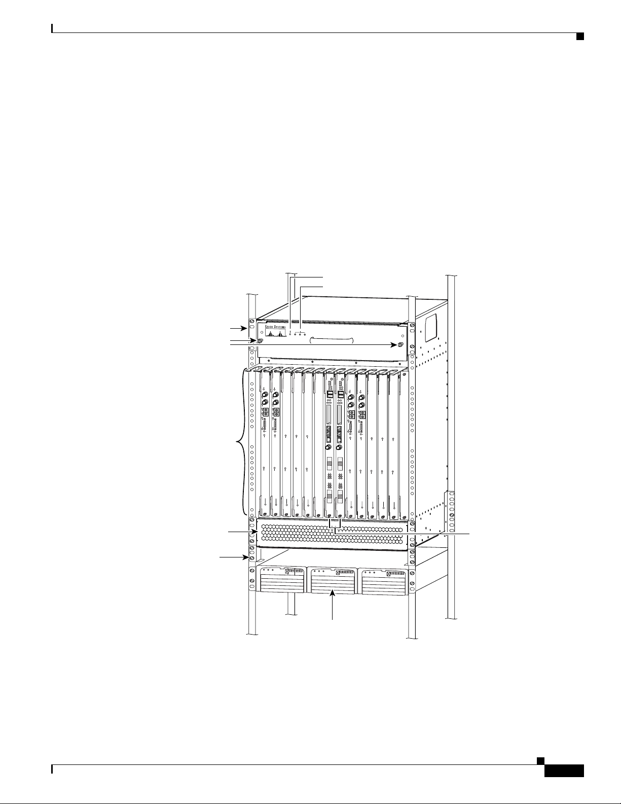
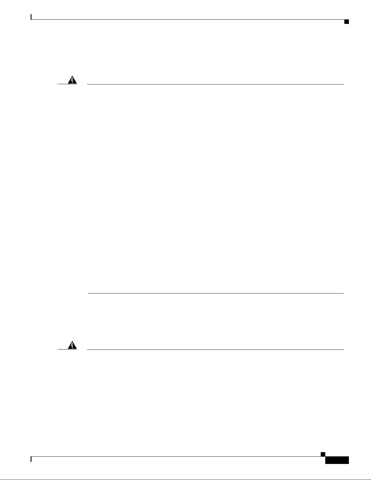
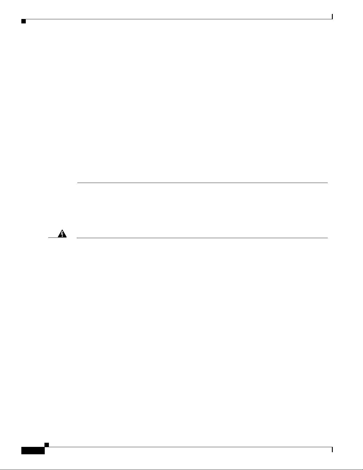
Figure 1 shows the Cisco AS5850 front view, and Figure 2 shows the rear view.
Figure 1 Cisco AS5850 Universal Gateway Fully Installed—Front View
Cooling module
Captive screws
Cisco AS5850 Overview
Power LED
Fault LEDs
Pow
er
Fault
B
a
n
k
1
B
a
n
k
2
B
a
n
k
3
14-slot card cage
(Line, port, and
RSC cards installed)
Cool air intake
Chassis installation
support bracket
L
O
O
P
L
O
O
P
R
C
V
R
R
C
V
R
X
M
T
R
L
O
S
X
M
T
R
L
O
S
T
3
E
N
A
B
L
E
/D
IS
A
B
L
E
T
3
E
N
A
B
L
E
/D
IS
A
B
L
E
R
R
X
X
R
A
R
A
T
T
X
X
L
A
L
A
M
A
M
A
S
E
R
IA
L
S
E
R
IA
L
S
E
R
I
A
L
S
E
R
IA
L
A
C
T
A
C
T
F
C
P
U
F
C
P
U
C
P
U
/P
O
W
E
R
C
P
U
/P
O
W
E
R
C
P
U
/P
O
W
E
R
C
P
U
/P
O
W
E
R
C
P
U
/P
O
W
E
R
C
A
L
L
S
/M
A
IN
T
C
A
L
L
S
/M
A
IN
T
C
A
L
L
S
/M
A
IN
T
C
A
L
L
S
/M
A
IN
T
C
A
L
L
S
/M
A
IN
216 UNIVERSAL PORTS
216 UNIVERSAL PORTS
CHANNELIZED T3 +
CHANNELIZED T3 +
P
O
R
T
S
TA
T
U
S
P
O
R
T
S
T
A
T
U
S
D
C
O
K
A
C
O
K
F
A
U
L
T
T
324 UNIVERSAL PORTS
324 UNIVERSAL PORTS
324 UNIVERSAL PORTS
P
O
R
T
S
T
A
T
U
S
P
O
R
T
S
T
A
T
U
S
P
O
R
T
S
T
A
T
U
S
D
C
O
K
A
C
L
O
O
P
L
O
O
P
R
C
V
R
R
C
V
R
X
M
T
R
L
O
S
X
M
T
R
L
O
S
T
3
E
N
A
B
L
E
/D
IS
A
B
L
E
T
3
E
N
A
B
L
E
/D
IS
A
B
L
E
R
R
X
X
R
A
R
A
T
T
X
X
L
A
L
A
M
A
M
A
S
E
R
IA
L
S
E
R
IA
L
S
E
R
IA
L
S
E
R
I
A
L
A
C
T
A
C
T
F
C
P
U
F
C
P
U
C
P
U
/P
O
W
E
R
C
P
U
/P
O
W
E
R
C
P
U
/P
O
W
E
R
C
P
U
/P
O
W
E
R
MBUS
PWR
MBUS
PWR
C
A
L
L
S
/M
A
IN
T
C
A
L
L
S
/M
A
IN
T
C
A
L
L
S
/M
A
IN
T
C
A
L
L
S
/M
A
IN
T
C
MIN
MIN
216 UNIVERSAL PORTS
216 UNIVERSAL PORTS
HIST
HIST
CHANNELIZED T3 +
MBUS
PWR
MBUS
PWR
MIN
MIN
HIST
HIST
P
O
R
T
S
T
A
T
U
S
P
O
K
F
A
U
L
T
A
324 UNIVERSAL PORTS
324 UNIVERSAL PORTS
324 UNIVERSAL PORTS
CHANNELIZED T3 +
O
R
T
S
T
A
T
U
S
P
O
R
T
S
T
A
T
U
S
P
O
R
T
S
T
A
T
U
S
D
C
O
K
A
C
O
K
F
A
U
L
T
2400W AC-input power shelf (optional)
C
P
U
/P
O
W
E
R
L
L
S
/M
A
IN
T
P
O
R
T
S
T
A
T
U
S
Route switch
controller (RSC) cards
56025
OL-10265-01
Cisco AS5850 Universal Gateway Regulatory Compliance and Safety Information
3
Page 4
Cisco AS5850 Overview
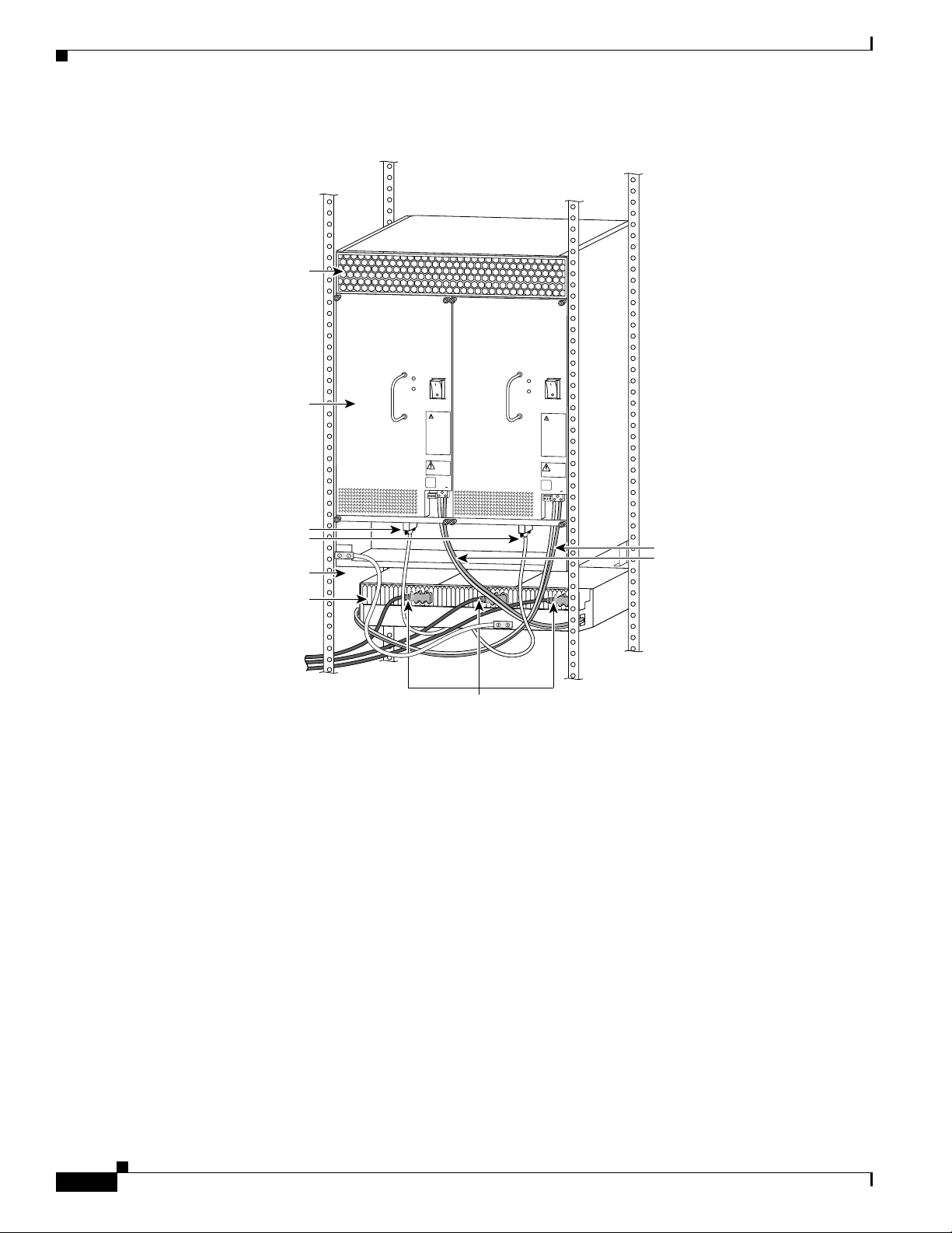
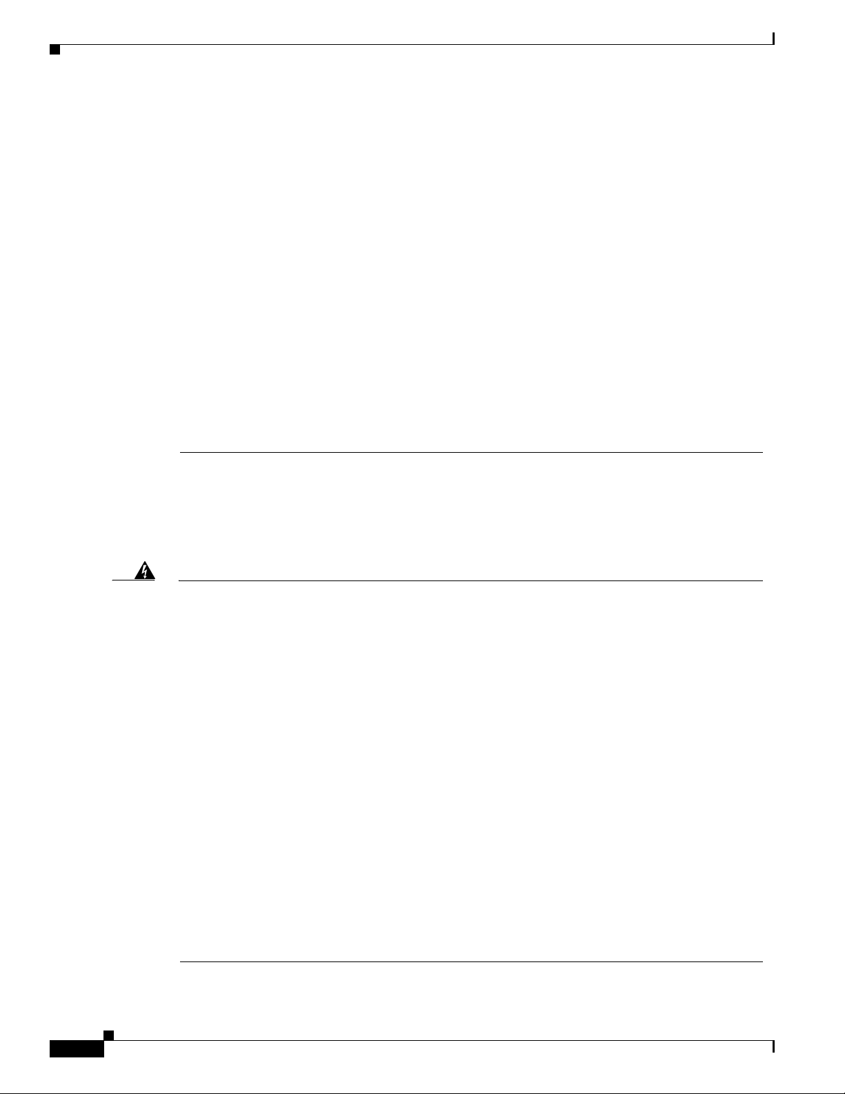
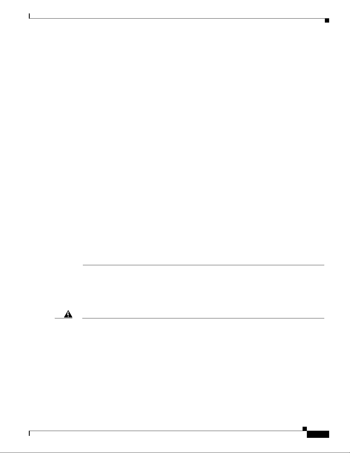
Figure 2 Cisco AS5850 Universal Gateway Fully Installed—Rear View
Warm air
exhaust
P
O
W
E
R
M
ISW
IRE
P
O
W
E
R
M
IS
W
IR
E
PEM
C
O
N
N
M
C
O
+
C
O
N
N
M
C
O
+
C power supply
monitor cables
Ground cable
DC interconnect
cables
2400W AC-input
power shelf
35395
AC connection
cables
The Cisco AS5850 is equipped with channelized T3 (CT3) or T1/E1 (CT1/E1) ingress interfaces that
provide a synchronous telecommunication interface in both North American and international
environments. These ingress interfaces are installed in the Cisco AS5850 and contain all necessary
functionality to terminate the telephone company connection.
The Cisco AS5850 universal gateway is also equipped with port cards that recognize Point-to-Point
Protocol (PPP) and Serial Line Interface Protocol (SLIP) framing that convert pulse code modulation
(PCM) analog bitstreams to digital data. The port card forwards converted and packetized data to the
main processor, which examines the data and forwards it to the routing logic, where the data is routed to
an external network.
The Cisco AS5850 is a 14-slot chassis that can support as many as 12 trunk or universal port cards, and
2 route switch controller cards. The chassis fits in a standard 19-inch, 4-post or standard 2-post telco
equipment rack.
Cisco AS5850 Universal Gateway Regulatory Compliance and Safety Information
4
OL-10265-01
Page 5

For European Union (E.U.) Use Only
The following operating conditions are required within the European Community:
The ports labeled “Network Clock,” “10/100 BASE-T,” “Console,” “AUX,” and “Alarms” are safety
extra-low voltage (SELV) circuits. SELV circuits should be connected only to other SELV circuits.
Because the E1 circuits are treated like telephone-network voltage, avoid connecting the SELV circuit
to the telephone network voltage (TNV) circuits.
Other usage invalidates any approval given to this apparatus if as a result it ceases to comply with
EN60950:1992.
Agency Approvals
Following are the agency approvals for the Cisco AS5850:
• Safety—UL 1950, CSA 22.2 No. 950, EN60950, ACA TS001, AS/NZS 3260, IEC 60950
• Emissions—CFR 47 Part 15 Class A (FCC), CISPR22 Class B, EN55022 Class B, AS/NRZ 3548
Class B, ICES003, VCCI Class B, CNS13438 Class A
• Immunity—IEC 1000-3-2, IEC 1000-3-3, IEC-1000-4-2, IEC-1000-4-3, IEC-1000-4-4,
IEC-1000-4-5, IEC-1000-4-6, IEC-1000-4-11, EN50082-1, EN50082-2
Cisco AS5850 Overview
24 Channelized T1/E1 Trunk Card Overview
The CT1/E1 trunk card resides in the Cisco AS5850 and contains all necessary functionality to terminate
the telco connections.
The 24 channnelized T1/E1 trunk card has three T1/E1 interfaces and each interface supports eight
T1/E1 PRI ports.The 24 channelized T1/E1 trunk card contains all necessary functionality to terminate
as many as 576 DS0 channels in T1 mode and 720 DS0 channels in E1 mode and uses onboard
High-Level Data Link Control (HDLC) controllers to terminate digital ISDN calls.
European Community Requirements
The following operating conditions are required within the European Community:
Except for Australia, the channelized E1 trunk card is designated SELV within the scope of
EN60950:1992.
Warning
The ports labeled “Network Clock,” “10BASE-T,” “Dial Shelf Interconnect,” “Console,” and “Alarms”
are safety extra-low voltage (SELV) circuits. SELV circuits should only be connected to other SELV
circuits. Because the E1/T1 circuits are treated like telephone-network voltage, avoid connecting the
SELV circuit to the telephone network voltage (TNV) circuits. To see translations of this warning, refer
to the “Translated Safety Warnings” section on page 10.
Other usage invalidates any approval given to this apparatus if as a result it ceases to comply with
EN60950:1992.
OL-10265-01
Cisco AS5850 Universal Gateway Regulatory Compliance and Safety Information
5
Page 6

Cisco AS5850 Overview
United States and Canadian Requirements
The channelized T3 trunk card meets the United States requirements for T3 support as specified in FCC
Part 68 standards.
The channelized T3 trunk card meets Canadian requirements for T3 support as specified in CP-01
standards.
Australia Safety Requirements
This customer equipment is to be installed and maintained by service personnel as defined by
AS/NZ3260 clause 1.2.14.3 Service Personnel. Incorrect connection of connected equipment to the
General Purpose Outlet could result in a hazardous situation.
Safety requirements are not fulfilled unless the equipment is connected to a wall socket outlet with
protective earth contact.
Europe Safety Requirements
The channelized T3 trunk card meets Pan-Euro requirements for T3 support as specified in CE-0168-X
standards.
The channelized T1/E1 trunk card meets United Kingdom (UK) requirements for E1 support as specified
in 607122 standards.
Japan Safety Requirements
The channelized T3 trunk card meets Japan requirements for T3 support as specified in JATE
T98-6304-0 standards.
The channelized T1/E1 trunk card meets Japan requirements for E1 support as specified in JATE
N98-N019-0 standards.
Singapore Safety Requirements
The channelized T1/E1 trunk card meets Singapore requirements for E1 support as specified in
ISDN2-IPTA-AE 0345-98 and DLCN1-MBPS-AO-0344-98 standards.
Scandinavia Safety Requirements
The channelized T1/E1 trunk card meets Sweden requirements for E1 support as specified in 98031130
standards.
Port Card Overview
The Cisco AS5850 is equipped with a maximum of 10 port cards that use Cisco’s universal port
technology with upgradeable firmware. The 324 universal port card (UPC) only handles ports and has
no external connections. The T1/E1 and T3 trunk cards each have external connections and the T3 trunk
card has additional capacity to handle 216 ports. Each port card plugs directly into the backplane and
has three or more LEDs, which indicate port card status. Port cards can be installed in slots numbered 0
through 5 or 8 through 13.
Cisco AS5850 Universal Gateway Regulatory Compliance and Safety Information
6
OL-10265-01
Page 7
The primary function of the port card is to convert pulse code modulation (PCM) analog bitstreams to
digital data. This is done by use of service provider elements (SPEs) and their associated firmware that
perform the modulation and demodulation of six analog bitstreams each. T3 trunk cards have 36 SPEs
each, and the UPC has 54 SPEs.
The port card forwards the converted and packetized data to the route switch controller (RSC). From the
RSC, the data is routed to the external network through Gigabit Ethernet interfaces.
Working with Lasers
• Fiber-optic ports are considered Class 1 laser or Class 1 LED ports.
• These products have been tested and found to comply with Class 1 limits of IEC 60825-1, IEC
• To avoid exposure to radiation, do not stare into the aperture of a fiber-optic port. Invisible radiation
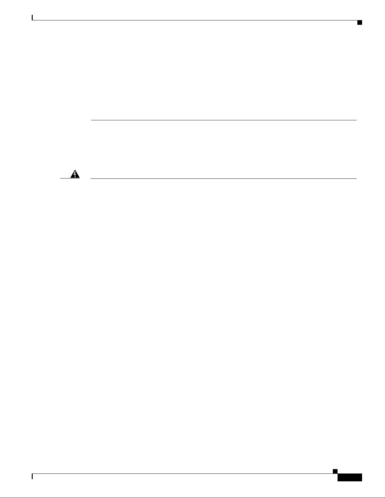
Table 1 shows the Class 1 laser label on the AS5850.
Table 1 Class 1 Laser Label
Safety Guidelines
60825-2, EN 60825-1, EN 60825-2, and 21CFR1040.
might be emitted from the aperture of the port when no fiber cable is connected.
CLASS 1 LASER PRODUCT
Fiber optic lasers, when they are installed, comply with DHHS Rules 21, CFR, Subchapter J,
applicable at date of manufacture.
Power Shelf
The AC-input power shelf is provided with three IEC 60320 Type C20 power inlets. If you are not using
one of the standard Cisco power cords designated for your country, please choose one that has an IEC
60320 Type C19 connector on one end and the appropriate country-specific plug on the other end. The
power cord should be rated at least 15 A at low voltages (100 to 120 VAC) and at least 10 A at high
voltages (200-240 VAC).
Safety Guidelines
This section provides safety guidelines to help you avoid injury to yourself and avoid damage to the
equipment. The following safety guidelines are recommended when working with any equipment that
connects to electrical power or telephone wiring:
• Locate the emergency power-off switch for the room in which you are working before beginning any
procedures requiring access to the chassis interior.
• Disconnect all power and external cables before moving a chassis.
• Never work alone if potentially hazardous conditions exist.
• Never assume that power has been disconnected from a circuit; always check.
OL-10265-01
• Never perform any action that creates a potential hazard to people or makes the equipment unsafe.
• Carefully examine your work area for possible hazards such as moist floors, ungrounded power
extension cables, and missing safety grounds.
Cisco AS5850 Universal Gateway Regulatory Compliance and Safety Information
7
Page 8
Safety Guidelines
• A 60-ampere DC circuit breaker is recommended for the input DC power source. This circuit
breaker should protect against short-circuit and overcurrent faults in accordance with United States
National Electrical Code NFPA 70 (United States), Canadian Electrical Code, part I, C22.1
(Canada), and IEC 364 (other countries).
• Only a DC power source that complies with the safety extra-low voltage (SELV) requirements in
UL1950, CSA 950, EN 60950, and IEC950 can be connected to the DC-input power supply.
• A readily accessible disconnect device must be incorporated in the fixed wiring.
• This unit is to be installed in a restricted access area in accordance with articles 110-16, 110-17, and
110-18 of the National Electric Code, ANSI/NFPA 70, and IEC 950.
Telephone Wiring Guidelines
The following guidelines are recommended when working with any equipment that is connected to
telephone wiring or to other network cabling:
• Never install telephone wiring during a lightning storm.
• Never install telephone jacks in wet locations unless the jack is specifically designed for wet
locations.
• Never touch uninsulated telephone wires or terminals unless the telephone line has been
disconnected at the network interface.
• Always use caution when installing or modifying telephone lines.
Lifting Safety
Note If you plan to install the chassis without using a forklift, you must first remove the blower assembly,
If you do not know how to safely install a system component correctly in a Cisco AS5850, contact a
qualified telecommunications engineer.
A fully configured dial shelf weighs approximately 278 lb (126.1 kg). The chassis is not intended to be
moved frequently. Before you install the dial shelf, ensure that your site is properly prepared so that you
can avoid having to move the chassis to accommodate power sources and network connections. (See the
Cisco AS5850 Universal Gateway Hardware Installation Guide for site requirement guidelines.)
PEMs, and cards from the chassis, and have someone assist you with the installation.
Whenever you lift any heavy components manually, follow these guidelines:
• Always have a second person available to help lift the component; never lift the component alone.
• Ensure that your footing is solid and balance the weight of the object between your feet.
• Lift the chassis slowly; never move suddenly or twist your body as you lift.
• Keep your back straight and lift with your legs, not your back. If you must bend down to lift the
assembly, bend at the knees, not at the waist, to reduce the strain on your lower back muscles.
Note Consider the total weight of the system to be lifted, and calculate at least one person for every 60 lb of
weight.
Cisco AS5850 Universal Gateway Regulatory Compliance and Safety Information
8
OL-10265-01
Page 9
Card Safety Recommendations
You must follow these safety instructions when installing any card in a Cisco AS5850. Failure to install
cards in accordance with these instructions invalidates the approval.
• The card might contain safety extra-low voltage (SELV) circuitry. Ensure that attachments at the
interconnection ports of the apparatus are also SELV circuits. (SELV circuits are designed and
protected so that, under both normal conditions and likely fault conditions, the voltage that can be
drawn is not hazardous.)
• Do not work on the system or connect and disconnect cables during a lightning storm.
Card Safety Recommendations
Warning
This equipment is intended to be grounded. Ensure that the host is connected to earth ground during
normal use. To see translations of this warning, refer to the “Translated Safety Warnings” section on
page 10.
If you do not know how to safely install a system component correctly in a Cisco AS5850, contact a
qualified telecommunications engineer.
General Installation Requirements
This section describes the general installation requirements for any feature card installed in a
Cisco AS5850.
Where applicable, each trunk card and port card is approved only for installation in a host and with host
attachments, which are either type approved for such apparatus or covered by a General Approval.
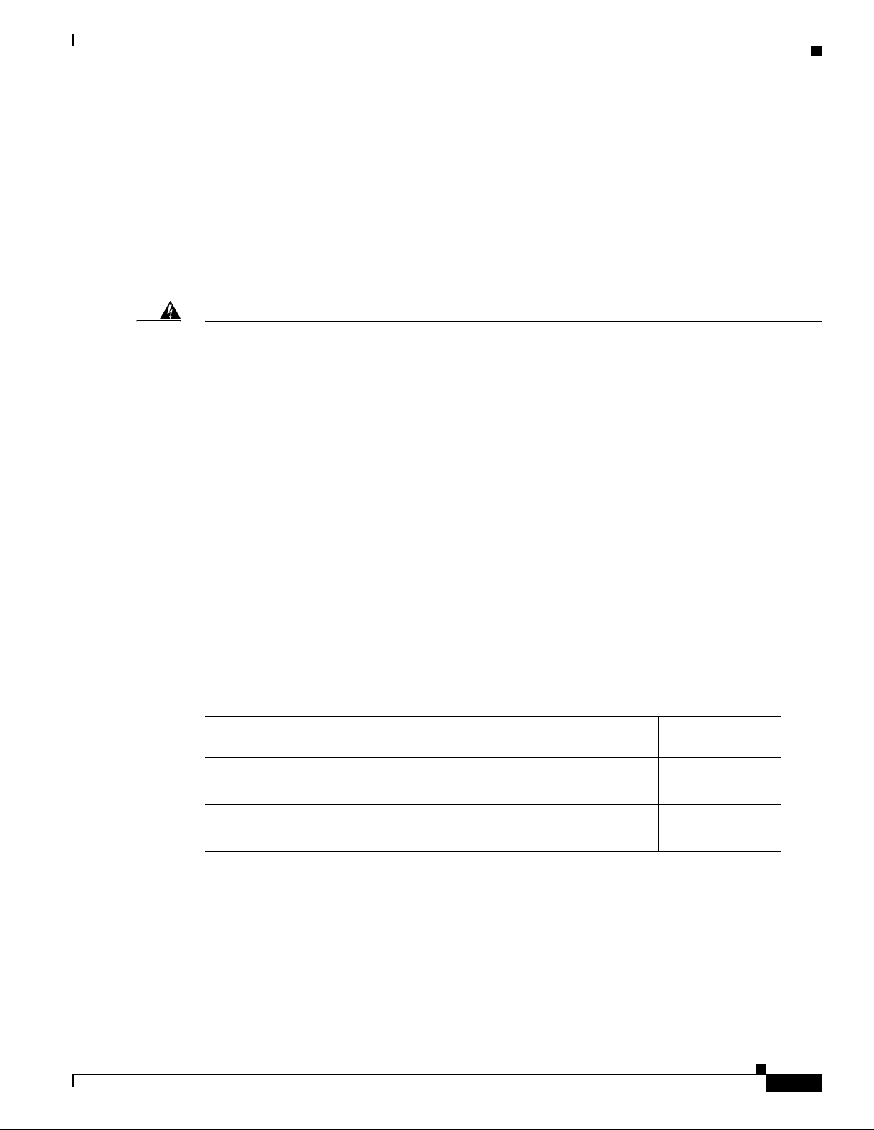
Clearance and creepage distances of X millimeters (mm) and Y mm, as listed in Table 2, must be
maintained between the feature card and other parts of the host, including any other feature cards.
Creepage distance is defined as the minimum distance between two points (following the contour of the
insulator) measured across the surface of an insulator. Clearance distance is defined as the minimum
distance between two points (line of sight) measured in air.
Table 2 Creepage and Clearance Distances Based on Voltage
Voltage Used or Generated by Other Parts of the Host
or Feature Card (Vrms
Up to 50 2.4 (3.8) 2.0
Up to 125 3.0 (4.8) 2.6
Up to 250 5.0 (8.0) 4.0
Up to 300
1. Vrms = root mean square voltage.
2. VDC = volts direct current.
3. The creepage distances not in parentheses apply when the equipment is installed in a normal office environment. The
4. For working voltages exceeding 300V, consult a competent telecommunications engineer prior to installation.
4
larger dimensions, given in parentheses, must be applied when the equipment is installed in an environment in which
dust and other types of pollution could conduct electricity because of the effects of dampness and condensation. This
applies to locations subject to high humidity.
1
or VDC2)
Creepage (Y mm)
3
Clearance (X mm)
6.4 (10.0) 4.0
OL-10265-01
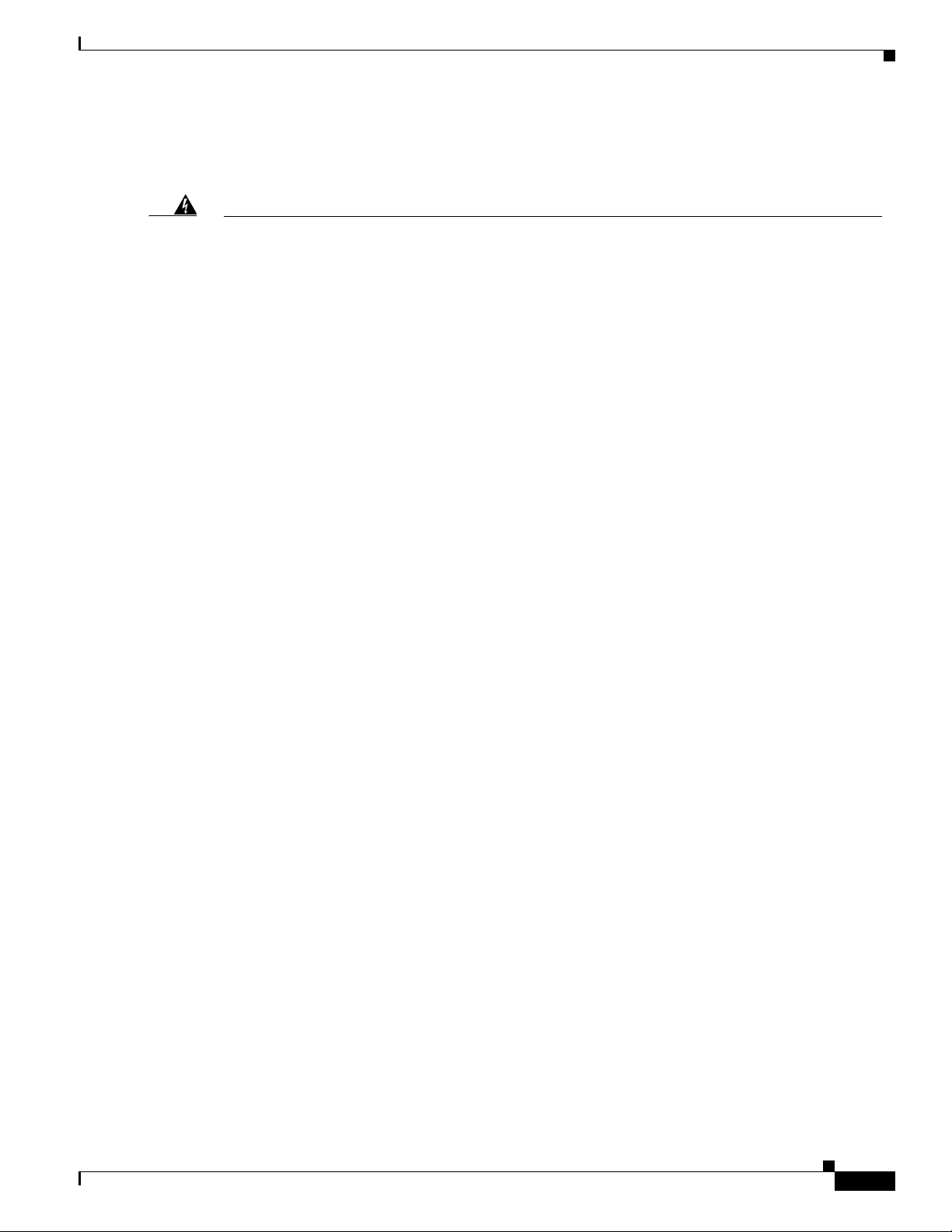
Clearance and creepage distances are measured between adjacent parts, as shown in Figure 3.
Cisco AS5850 Universal Gateway Regulatory Compliance and Safety Information
9
Page 10
Translated Safety Warnings
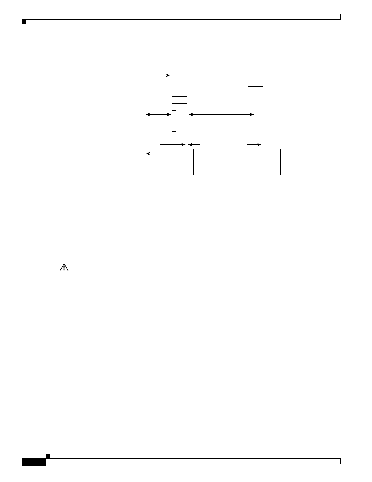
Figure 3 Creepage and Clearance Distance Measurements
Note that in Figure 3, X indicates the clearance distances between the cards and between adjacent cards
and components, and Y shows the creepage path across the surface of an insulator and between the two
points indicated by X.
Communication module
Power supply unit
or other source of
excessive voltage
Carrier card Feature card
XX
Y
Y
10328
GR-1089 Intrabuilding Lightning Immunity Requirement
The GR-1089 Intrabuilding Lightning Immunity Specification requires the use of grounded, shielded
cabling.
Caution To be in compliance with GR-1089-Core Intra-building Lightning immunity requirements, you must use
grounded, shielded cabling.
Translated Safety Warnings
This section repeats in multiple languages the warnings in the Cisco AS5850 Universal Gateway
Hardware Installation Guide publication. In addition, this section contains translated warnings that can
be used with other documentation related to the Cisco AS5850. The following translated warnings are
provided:
• Warning Definition, page 11
• Power Disconnection Warning, page 13
• Chassis Warning—Disconnecting Telephone-Network Cables, page 13
• Lightning Activity Warning, page 14
• Chassis Lifting Warning, page 15
• DC Power Disconnection Warning, page 16
• DC Power Connection Warning, page 17
10
• DC Power Supply Wiring Warning, page 18
Cisco AS5850 Universal Gateway Regulatory Compliance and Safety Information
OL-10265-01
Page 11
• Installation Warning, page 19
• Power Supply Disconnection Warning, page 20
• Chassis Warning—Rack-Mounting and Servicing, page 21
• TN Power Warning, page 23
• ISDN Connection Warning, page 24
• Warning Statement for Norway and Sweden, page 25
• Restricted Area Warning, page 26
• Battery Handling Warning, page 27
• Power Cabling Warning, page 28
• Grounded Equipment Warning, page 29
• Product Disposal Warning, page 29
• Ground Connection Warning, page 30
• Jewelry Removal Warning, page 31
• Qualified Personnel Warning, page 32
• Supply Circuit Warning, page 32
• SELV Circuit Warning, page 33
• Hazardous Voltages in WAN Ports, page 34
Translated Safety Warnings
• Incorrect Connection Warning, page 35
• SELV Circuit Warning, page 36
• Power Cord Warning, page 37
• Service Personnel Warning, page 38
• Telecommunications Lines Warning, page 39
• Customer Equipment Warning, page 40
• No. 26 AWG Warning, page 41
• Ground Conductor Warning, page 42
• Chassis Power Connection, page 43
• Card Handling Warning, page 44
Warning Definition
Safety warnings appear throughout the Cisco AS5850 Universal Gateway Hardware Installation Guide
in procedures that, if performed incorrectly, may harm you. A warning symbol precedes each warning
statement.
OL-10265-01
Cisco AS5850 Universal Gateway Regulatory Compliance and Safety Information
11
Page 12
Translated Safety Warnings
Warning
Waarschuwing
Varoitus
Attention
Warnung
Avvertenza
This warning symbol means danger. You are in a situation that could cause bodily injury. Before you
work on any equipment, be aware of the hazards involved with electrical circuitry and be familiar
with standard practices for preventing accidents.
Dit waarschuwingssymbool betekent gevaar. U verkeert in een situatie die lichamelijk letsel
kan veroorzaken. Voordat u aan enige apparatuur gaat werken, dient u zich bewust te zijn van
de bij elektrische schakelingen betrokken risico's en dient u op de hoogte te zijn van standaard
maatregelen om ongelukken te voorkomen.
Tämä varoitusmerkki merkitsee vaaraa. Olet tilanteessa, joka voi johtaa ruumiinvammaan.
Ennen kuin työskentelet minkään laitteiston parissa, ota selvää sähkökytkentöihin liittyvistä
vaaroista ja tavanomaisista onnettomuuksien ehkäisykeinoista.
Ce symbole d'avertissement indique un danger. Vous vous trouvez dans une situation pouvant
causer des blessures ou des dommages corporels. Avant de travailler sur un équipement, soyez
conscient des dangers posés par les circuits électriques et familiarisez-vous avec les
procédures couramment utilisées pour éviter les accidents.
Dieses Warnsymbol bedeutet Gefahr. Sie befinden sich in einer Situation, die zu einer
Körperverletzung führen könnte. Bevor Sie mit der Arbeit an irgendeinem Gerät beginnen, seien
Sie sich der mit elektrischen Stromkreisen verbundenen Gefahren und der Standardpraktiken
zur Vermeidung von Unfällen bewußt.
Questo simbolo di avvertenza indica un pericolo. La situazione potrebbe causare infortuni alle
persone. Prima di lavorare su qualsiasi apparecchiatura, occorre conoscere i pericoli relativi
ai circuiti elettrici ed essere al corrente delle pratiche standard per la prevenzione di incidenti.
Advarsel
Aviso
¡Advertencia!
Varning!
Dette varselsymbolet betyr fare. Du befinner deg i en situasjon som kan føre til personskade. Før
du utfører arbeid på utstyr, må du vare oppmerksom på de faremomentene som elektriske kretser
innebærer, samt gjøre deg kjent med vanlig praksis når det gjelder å unngå ulykker.
Este símbolo de aviso indica perigo. Encontra-se numa situação que lhe poderá causar danos
físicos. Antes de começar a trabalhar com qualquer equipamento, familiarize-se com os perigos
relacionados com circuitos eléctricos, e com quaisquer práticas comuns que possam prevenir
possíveis acidentes.
Este símbolo de aviso significa peligro. Existe riesgo para su integridad física. Antes de
manipular cualquier equipo, considerar los riesgos que entraña la corriente eléctrica y
familiarizarse con los procedimientos estándar de prevención de accidentes.
Denna varningssymbol signalerar fara. Du befinner dig i en situation som kan leda till
personskada. Innan du utför arbete på någon utrustning måste du vara medveten om farorna med
elkretsar och känna till vanligt förfarande för att förebygga skador.
12
Cisco AS5850 Universal Gateway Regulatory Compliance and Safety Information
OL-10265-01
Page 13
Power Disconnection Warning
Translated Safety Warnings
Warning
Waarschuwing
Varoitus
Attention
Warnung
Avvertenza
Advarsel
Aviso
Before working on a system that has an on/off switch, turn OFF the power and unplug the power
cord.
Voordat u aan een systeem werkt dat een aan/uit schakelaar heeft, dient u de stroomvoorziening
UIT te schakelen en de stekker van het netsnoer uit het stopcontact te halen.
Ennen kuin teet mitään sellaiselle järjestelmälle, jossa on kaksiasentokytkin, katkaise siitä
virta ja kytke virtajohto irti.
Avant de travailler sur un système équipé d'un commutateur marche-arrêt, mettre l'appareil à
l'arrêt (OFF) et débrancher le cordon d'alimentation.
Bevor Sie an einem System mit Ein/Aus-Schalter arbeiten, schalten Sie das System AUS und
ziehen das Netzkabel aus der Steckdose.
Prima di lavorare su un sistema dotato di un interruttore on/off, spegnere (OFF) il sistema e
staccare il cavo dell’alimentazione.
Slå AV strømmen og trekk ut strømledningen før det utføres arbeid på et system som er utstyrt
med en av/på-bryter.
Antes de começar a trabalhar num sistema que tem um interruptor on/off, DESLIGUE a corrente
eléctrica e retire o cabo de alimentação da tomada.
¡Advertencia!
Varning!
Antes de utilizar cualquier sistema equipado con interruptor de Encendido/Apagado (ON/OFF),
cortar la alimentación y desenchufar el cable de alimentación.
Slå AV strömmen och dra ur nätsladden innan du utför arbete på ett system med strömbrytare.
Chassis Warning—Disconnecting Telephone-Network Cables
Warning
Waarschuwing
Varoitus
Before opening the chassis, disconnect the telephone-network cables to avoid contact with
telephone-network voltages.
Voordat u het frame opent, dient u de verbinding met het telefoonnetwerk te verbreken door de
kabels te ontkoppelen om zo contact met telefoonnetwerk-spanningen te vermijden.
Vältä joutumista kosketuksiin puhelinverkostojännitteiden kanssa irrottamalla
puhelinverkoston kaapelit ennen asennuspohjan aukaisemista.
OL-10265-01
Cisco AS5850 Universal Gateway Regulatory Compliance and Safety Information
13
Page 14
Translated Safety Warnings
Attention
Avant d'ouvrir le châssis, débrancher les câbles du réseau téléphonique afin d'éviter tout
contact avec les tensions d'alimentation du réseau téléphonique.
Warnung
Bevor Sie das Chassis öffnen, ziehen Sie die Telefonnetzkabel aus der Verbindung, um Kontakt
mit Telefonnetzspannungen zu vermeiden.
Avvertenza
Prima di aprire il telaio, scollegare i cavi della rete telefonica per evitare di entrare in contatto
con la tensione di rete.
Advarsel
Før kabinettet åpnes, skal kablene for telenettet kobles fra for å unngå å komme i kontakt med
spenningen i telenettet.
Aviso
Antes de abrir o chassis, desligue os cabos da rede telefónica para evitar contacto com a tensão
da respectiva rede.
¡Advertencia!
Antes de abrir el chasis, desconectar el cableado dirigido a la red telefónica para evitar
contacto con voltajes de la propia red.
Varning!
Koppla loss ledningarna till telefonnätet innan du öppnar chassit så att kontakten med
telefonnätsspänningen bryts.
Lightning Activity Warning
Warning
Waarschuwing
Varoitus
Attention
Warnung
Avvertenza
Advarsel
Aviso
¡Advertencia!
Varning!
Do not work on the system or connect or disconnect cables during periods of lightning activity.
Tijdens onweer dat gepaard gaat met bliksem, dient u niet aan het systeem te werken of kabels
aan te sluiten of te ontkoppelen.
Älä työskentele järjestelmän parissa äläkä yhdistä tai irrota kaapeleita ukkosilmalla.
Ne pas travailler sur le système ni brancher ou débrancher les câbles pendant un orage.
Arbeiten Sie nicht am System und schließen Sie keine Kabel an bzw. trennen Sie keine ab, wenn
es gewittert.
Non lavorare sul sistema o collegare oppure scollegare i cavi durante un temporale con fulmini.
Utfør aldri arbeid på systemet, eller koble kabler til eller fra systemet når det tordner eller lyner.
Não trabalhe no sistema ou ligue e desligue cabos durante períodos de mau tempo (trovoada).
No operar el sistema ni conectar o desconectar cables durante el transcurso de descargas
eléctricas en la atmósfera.
Vid åska skall du aldrig utföra arbete på systemet eller ansluta eller koppla loss kablar.
14
Cisco AS5850 Universal Gateway Regulatory Compliance and Safety Information
OL-10265-01
Page 15
Chassis Lifting Warning
Translated Safety Warnings
Warning
Waarschuwing
Varoitus
Attention
Two people are required to lift the chassis. Grasp the chassis underneath the lower edge and lift
with both hands. To prevent injury, keep your back straight and lift with your legs, not your back. To
prevent damage to the chassis and components, never attempt to lift the chassis with the handles
on the power supplies or on the interface processors, or by the plastic panels on the front of the
chassis. These handles were not designed to support the weight of the chassis.
Er zijn twee mensen nodig om het frame op te tillen. Het frame dient onder de onderste rand
vastgegrepen en met beide handen omhooggetild te worden. Om te voorkomen dat u letsel
oploopt, dient u uw rug recht te houden en met behulp van uw benen, niet uw rug, te tillen. Om
schade aan het frame en de onderdelen te voorkomen, mag u nooit proberen om het frame op te
tillen aan de handvatten op de voedingen of op de interface-processors of aan de kunststof
panelen aan de voorkant van het frame. Deze handvatten zijn niet ontworpen om het gewicht van
het frame te dragen.
Asennuspohjan nostamiseen tarvitaan kaksi henkilöä. Ota ote asennuspohjan alareunasta ja
nosta molemmin käsin. Pitäen selkäsi suorana nosta jalkojen (ei selän) avulla, jotta välttäisit
loukkaantumista. Älä yritä nostaa asennuspohjaa virtalähteen tai liitäntäprosessorin kahvoista
tai asennuspohjan etuosan muovipaneeleista, jotta estät asennuspohjan ja rakenneosien
vaurioitumisen. Näitä kahvoja ei ole suunniteltu kestämään asennuspohjan painoa.
Il faut deux personnes pour soulever le châssis. Le saisir par son rebord inférieur et soulever
des deux mains. Pour éviter tout trauma de la région lombaire, garder le dos droit et soulever la
charge en redressant les jambes. Pour éviter d'endommager le châssis et ses composants, ne
jamais tenter de le soulever par les poignées des blocs d'alimentation ou des processeurs
d'interface, ni par les panneaux en plastique à l'avant du châssis. Ces poignées ne sont pas
prévues pour supporter le poids du châssis.
Avvertenza
OL-10265-01
Warnung
Advarsel
Zum Anheben des Chassis werden zwei Personen benötigt. Fassen Sie das Chassis unterhalb
der unteren Kante an und heben es mit beiden Händen an. Um Verletzungen zu vermeiden, ist der
Rücken aufrecht zu halten und das Gewicht mit den Beinen, nicht mit dem Rücken, anzuheben.
Um Schäden an Chassis und Bauteilen zu vermeiden, heben Sie das Chassis nie an den
Kunststoffabdeckungen vorne am Chassis oder mit den Griffen am Netzgerät oder an den
Schnittstellenprozessoren an. Diese Griffe sind nicht so konstruiert, daß sie das Gewicht des
Chassis tragen könnten.
Il telaio va sollevato da due persone. Afferrare il telaio al di sotto del bordo inferiore e sollevare
con entrambe le mani. Per evitare infortuni, mantenere la schiena diritta e sollevare il peso con
le gambe, non con la schiena. Per evitare danni al telaio ed ai componenti, non provare mai a
sollevare il telaio tramite le maniglie sugli alimentatori o sui processori di interfaccia oppure
tramite i pannelli in plastica sulla parte anteriore del telaio. Queste maniglie non sono state
progettate per sostenere il peso del telaio.
Det er nødvendig med to personer for å løfte kabinettet. Ta tak i kabinettet under den nedre
kanten, og løft med begge hender. Unngå personskade ved å holde ryggen rett og løfte med bena,
ikke ryggen. Unngå skade på kabinettet og komponentene ved å aldri prøve å løfte kabinettet
etter håndtakene på strømforsyningsenhetene, grensesnittprosessorene eller i plastpanelene
foran på kabinettet. Disse håndtakene er ikke beregnet på å tåle vekten av kabinettet.
Cisco AS5850 Universal Gateway Regulatory Compliance and Safety Information
15
Page 16
Translated Safety Warnings
Aviso
¡Advertencia!
Varning!
São necessárias duas pessoas para levantar o chassis. Agarre o chassis imediatamente abaixo
da margem inferior, e levante-o com ambas as mãos. Para evitar lesões, mantenha as suas
costas direitas e levante o peso com ambas as pernas, sem forçar as costas. Para prevenir
danos no chassis e nos seus componentes, nunca tente levantá-lo pelas asas das unidades
abastecedoras de energia, nem pelos processadores de interface, ou pelos painéis plásticos
localizados na frente do chassis. Estas asas não foram criadas para suportar o peso do chassis.
Se necesitan dos personas para levantar el chasis. Sujete el chasis con las dos manos por
debajo del borde inferior y levántelo. Para evitar lesiones, mantenga la espalda recta y
levántelo con la fuerza de las piernas y no de la espalda. Para evitar daños al chasis y a sus
componentes, no intente nunca levantar el chasis por las asas de las fuentes de alimentación o
de los procesadores de interfase, ni por los paneles de plástico situados en el frontal del chasis.
Las asas no han sido diseñadas para soportar el peso del chasis.
Det krävs två personer för att lyfta chassit. Fatta tag i chassit under den nedre kanten och lyft
med båda händerna. För att undvika skador skall du hålla ryggen rak och lyfta med benen, inte
ryggen. Chassit och delarna kan skadas om du försöker lyfta chassit i handtagen på
strömförsörjningsenheterna eller gränssnittsprocessorerna, eller i plastpanelerna på chassits
framsida. Handtagen är inte konstruerade för att hålla chassits tyngd.
DC Power Disconnection Warning
Warning
Waarschuwing
Varoitus
Attention
Before performing any of the following procedures, ensure that power is removed from the DC
circuit. To ensure that all power is OFF, locate the circuit breaker on the panel board that services
the DC circuit, switch the circuit breaker to the OFF position, and tape the switch handle of the
circuit breaker in the OFF position.
Voordat u een van de onderstaande procedures uitvoert, dient u te controleren of de stroom naar
het gelijkstroom circuit uitgeschakeld is. Om u ervan te verzekeren dat alle stroom UIT is
geschakeld, kiest u op het schakelbord de stroomverbreker die het gelijkstroom circuit bedient,
draait de stroomverbreker naar de UIT positie en plakt de schakelaarhendel van de
stroomverbreker met plakband in de UIT positie vast.
Varmista, että tasavirtapiirissä ei ole virtaa ennen seuraavien toimenpiteiden suorittamista.
Varmistaaksesi, että virta on KATKAISTU täysin, paikanna tasavirrasta huolehtivassa
kojetaulussa sijaitseva suojakytkin, käännä suojakytkin KATKAISTU-asentoon ja teippaa
suojakytkimen varsi niin, että se pysyy KATKAISTU-asennossa.
Avant de pratiquer l'une quelconque des procédures ci-dessous, vérifier que le circuit en
courant continu n'est plus sous tension. Pour en être sûr, localiser le disjoncteur situé sur le
panneau de service du circuit en courant continu, placer le disjoncteur en position fermée (OFF)
et, à l'aide d'un ruban adhésif, bloquer la poignée du disjoncteur en position OFF.
16
Cisco AS5850 Universal Gateway Regulatory Compliance and Safety Information
OL-10265-01
Page 17
Translated Safety Warnings
Warnung
Avvertenza
Advarsel
Aviso
¡Advertencia!
Vor Ausführung der folgenden Vorgänge ist sicherzustellen, daß die Gleichstromschaltung
keinen Strom erhält. Um sicherzustellen, daß sämtlicher Strom abgestellt ist, machen Sie auf
der Schalttafel den Unterbrecher für die Gleichstromschaltung ausfindig, stellen Sie den
Unterbrecher auf AUS, und kleben Sie den Schaltergriff des Unterbrechers mit Klebeband in der
AUS-Stellung fest.
Prima di svolgere una qualsiasi delle procedure seguenti, verificare che il circuito CC non sia
alimentato. Per verificare che tutta l’alimentazione sia scollegata (OFF), individuare
l’interruttore automatico sul quadro strumenti che alimenta il circuito CC, mettere l’interruttore
in posizione OFF e fissarlo con nastro adesivo in tale posizione.
Før noen av disse prosedyrene utføres, kontroller at strømmen er frakoblet likestrømkretsen.
Sørg for at all strøm er slått AV. Dette gjøres ved å lokalisere strømbryteren på brytertavlen som
betjener likestrømkretsen, slå strømbryteren AV og teipe bryterhåndtaket på strømbryteren i
AV-stilling.
Antes de executar um dos seguintes procedimentos, certifique-se que desligou a fonte de
alimentação de energia do circuito de corrente contínua. Para se assegurar que toda a corrente
foi DESLIGADA, localize o disjuntor no painel que serve o circuito de corrente contínua e
coloque-o na posição OFF (Desligado), segurando nessa posição a manivela do interruptor do
disjuntor com fita isoladora.
Antes de proceder con los siguientes pasos, comprobar que la alimentación del circuito de
corriente continua (CC) esté cortada (OFF). Para asegurarse de que toda la alimentación esté
cortada (OFF), localizar el interruptor automático en el panel que alimenta al circuito de
corriente continua, cambiar el interruptor automático a la posición de Apagado (OFF), y sujetar
con cinta la palanca del interruptor automático en posición de Apagado (OFF).
Varning!
Innan du utför någon av följande procedurer måste du kontrollera att strömförsörjningen till
likströmskretsen är bruten. Kontrollera att all strömförsörjning är BRUTEN genom att slå AV det
överspänningsskydd som skyddar likströmskretsen och tejpa fast överspänningsskyddets
omkopplare i FRÅN-läget.
DC Power Connection Warning
Warning
Waarschuwing
Varoitus
Attention
After wiring the DC power supply, remove the tape from the circuit breaker switch handle and
reinstate power by moving the handle of the circuit breaker to the ON position.
Nadat de bedrading van de gelijkstroom voeding aangebracht is, verwijdert u het plakband van
de schakelaarhendel van de stroomverbreker en schakelt de stroom weer in door de hendel van
de stroomverbreker naar de AAN positie te draaien.
Yhdistettyäsi tasavirtalähteen johdon avulla poista teippi suojakytkimen varresta ja kytke virta
uudestaan kääntämällä suojakytkimen varsi KYTKETTY-asentoon.
Une fois l'alimentation connectée, retirer le ruban adhésif servant à bloquer la poignée du
disjoncteur et rétablir l'alimentation en plaçant cette poignée en position de marche (ON).
OL-10265-01
Cisco AS5850 Universal Gateway Regulatory Compliance and Safety Information
17
Page 18

Translated Safety Warnings
Warnung
Avvertenza
Advarsel
Aviso
¡Advertencia!
Varning!
Nach Verdrahtung des Gleichstrom-Netzgeräts entfernen Sie das Klebeband vom Schaltergriff
des Unterbrechers und schalten den Strom erneut ein, indem Sie den Griff des Unterbrechers auf
EIN stellen.
Dopo aver eseguito il cablaggio dell’alimentatore CC, togliere il nastro adesivo dall’interruttore
automatico e ristabilire l’alimentazione spostando all'interruttore automatico in posizione ON.
Etter at likestrømsenheten er tilkoblet, fjernes teipen fra håndtaket på strømbryteren, og
deretter aktiveres strømmen ved å dreie håndtaket på strømbryteren til PÅ-stilling.
Depois de ligar o sistema de fornecimento de corrente contínua, retire a fita isoladora da
manivela do disjuntor, e volte a ligar a corrente ao deslocar a manivela para a posição ON
(Ligado).
Después de cablear la fuente de alimentación de corriente continua, retirar la cinta de la
palanca del interruptor automático, y restablecer la alimentación cambiando la palanca a la
posición de Encendido (ON).
När du har kopplat ledningarna till strömförsörjningsenheten för inmatad likström tar du bort
tejpen från överspänningsskyddets omkopplare och slår på strömmen igen genom att ställa
överspänningsskyddets omkopplare i TILL-läget.
DC Power Supply Wiring Warning
Warning
Waarschuwing
Varoitus
Attention
The illustration shows the DC power supply terminal block. Wire the DC power supply using the
appropriate lugs at the wiring end, as illustrated. The proper wiring sequence is ground to ground,
positive to positive (line to L), and negative to negative (neutral to N). Note that the ground wire
should always be connected first and disconnected last.
De figuur toont de aansluitstrip van de gelijkstroomvoeding. Breng de bedrading aan voor de
gelijkstroomvoeding met behulp van de juiste aansluitpunten aan het draadeinde zoals
aangegeven. De juiste bedradingsvolgorde is aarde naar aarde, positief naar positief (lijn naar
L) en negatief naar negatief (neutraal naar N). Let op dat de aarddraad altijd het eerst verbonden
en het laatst losgemaakt wordt.
Kuva esittää tasavirran pääterasiaa. Liitä tasavirtalähde johdon avulla käyttäen sopivia
kiinnityskorvia johdon päässä kuvan esittämällä tavalla. Oikea kytkentäjärjestys on maajohto
maajohtoon, positiivinen positiiviseen (johto L:ään) ja negatiivinen negatiiviseen (nollajohto
N:ään). Ota huomioon, että maajohto on aina yhdistettävä ensin ja irrotettava viimeisenä.
La figure illustre le bloc de connexion de l'alimentation en courant continu. Câbler
l'alimentation en courant continu en fixant les cosses qui conviennent aux extrémités câblées
conformément au schéma. La séquence de câblage à suivre est terre-terre, positif-positif (ligne
sur L), et négatif-négatif (neutre sur N). Noter que le fil de masse doit toujours être connecté en
premier et déconnecté en dernier.
18
Cisco AS5850 Universal Gateway Regulatory Compliance and Safety Information
OL-10265-01
Page 19

Translated Safety Warnings
Warnung
Avvertenza
Advarsel
Aviso
¡Advertencia!
Die Abbildung zeigt den Terminalblock des Gleichstrom-Netzgeräts. Verdrahten Sie das
Gleichstrom-Netzgerät unter Verwendung von geeigneten Kabelschuhen am Verdrahtungsende
(siehe Abbildung). Die richtige Verdrahtungsfolge ist Erde an Erde, positiv an positiv (Leitung an
L) und negativ an negativ (neutral an N). Beachten Sie bitte, daß der Erdungsdraht immer als
erster verbunden und als letzter abgetrennt werden sollte.
L’illustrazione mostra la morsettiera dell alimentatore CC. Cablare l’alimentatore CC usando i
connettori adatti all’estremità del cablaggio, come illustrato. La corretta sequenza di cablaggio
è da massa a massa, da positivo a positivo (da linea ad L) e da negativo a negativo (da neutro a
N). Tenere presente che il filo di massa deve sempre venire collegato per primo e scollegato per
ultimo.
Figuren viser likestrømforsyningsenhetens tilkoplingsterminal. Likestrømforsyningsenheten
tilkoples ved hjelp av passende kabelsko som festes i enden av ledningene, slik som vist i
figuren. Riktig tilkoplingssekvens er jord til jord, positiv til positv (linje til L), og negativ til
negativ (nøytral til N). Husk at jordingsledningen alltid bør tilkoples først og frakoples sist.
A figura mostra o bloco do terminal de fornecimento de corrente contínua. Ligue o fornecimento
de corrente contínua utilizando as extremidades apropriadas no final do cabo, conforme
ilustrado. A sequência correcta de instalação é terra-a-terra, positivo-positivo (linha para L), e
negativo-negativo (neutro para N). Note que o fio de terra deverá ser sempre o primeiro a ser
ligado, e o último a ser desligado.
La figura muestra la caja de bornes de la fuente de alimentación. Cablear la fuente de
alimentación de corriente continua, usando las lengüetas de conexión apropiadas, en el
extremo del cable tal como se muestra. Las conexiones deben realizarse en el siguiente orden:
tierra con tierra, positivo con positivo (la línea con la L) y negativo con negativo (el neutro con
la N). Tenga en cuenta que el conductor de tierra siempre tiene que conectarse el primero y
desconectarse el último.
Varning!
Illustrationen visar anslutningsplinten för likströmförsörjningsenheten. Koppla ledningarna till
strömförsörjningsenheten med lämpliga kabelskor i ledningsändarna som bilden visar. Korrekt
kopplingssekvens är jord till jord, positiv till positiv (linje till L) och negativ till negativ (neutral
till N). Observera att jordledningen alltid skall anslutas först och kopplas bort sist.
Installation Warning
Warning
Waarschuwing
Varoitus
Attention
Warnung
Read the installation instructions before you connect the system to its power source.
Raadpleeg de installatie-aanwijzingen voordat u het systeem met de voeding verbindt.
Lue asennusohjeet ennen järjestelmän yhdistämistä virtalähteeseen.
Avant de brancher le système sur la source d'alimentation, consulter les directives
d'installation.
Lesen Sie die Installationsanweisungen, bevor Sie das System an die Stromquelle anschließen.
OL-10265-01
Cisco AS5850 Universal Gateway Regulatory Compliance and Safety Information
19
Page 20

Translated Safety Warnings
Avvertenza
Advarsel
Aviso
¡Advertencia!
Varning!
Consultare le istruzioni di installazione prima di collegare il sistema all’alimentatore.
Les installasjonsinstruksjonene før systemet kobles til strømkilden.
Leia as instruções de instalação antes de ligar o sistema à sua fonte de energia.
Ver las instrucciones de instalación antes de conectar el sistema a la red de alimentación.
Läs installationsanvisningarna innan du kopplar systemet till dess strömförsörjningsenhet.
Power Supply Disconnection Warning
Warning
Waarschuwing
Before working on a chassis or working near power supplies, unplug the power cord on AC units;
disconnect the power at the circuit breaker on DC units.
Voordat u aan een frame of in de nabijheid van voedingen werkt, dient u bij wisselstroom
toestellen de stekker van het netsnoer uit het stopcontact te halen; voor gelijkstroom toestellen
dient u de stroom uit te schakelen bij de stroomverbreker.
Varoitus
Attention
Warnung
Avvertenza
Advarsel
Aviso
Kytke irti vaihtovirtalaitteiden virtajohto ja katkaise tasavirtalaitteiden virta suojakytkimellä,
ennen kuin teet mitään asennuspohjalle tai työskentelet virtalähteiden läheisyydessä.
Avant de travailler sur un châssis ou à proximité d'une alimentation électrique, débrancher le
cordon d'alimentation des unités en courant alternatif ; couper l'alimentation des unités en
courant continu au niveau du disjoncteur.
Bevor Sie an einem Chassis oder in der Nähe von Netzgeräten arbeiten, ziehen Sie bei
Wechselstromeinheiten das Netzkabel ab bzw. schalten Sie bei Gleichstromeinheiten den
Strom am Unterbrecher ab.
Prima di lavorare su un telaio o intorno ad alimentatori, scollegare il cavo di alimentazione sulle
unità CA; scollegare l'alimentazione all’interruttore automatico sulle unità CC.
Før det utføres arbeid på kabinettet eller det arbeides i nærheten av str¿mforsyningsenheter,
skal str¿mledningen trekkes ut pÅ vekselstrømsenheter og strømmen kobles fra ved
strømbryteren på likestrømsenheter.
Antes de trabalhar num chassis, ou antes de trabalhar perto de unidades de fornecimento de
energia, desligue o cabo de alimentação nas unidades de corrente alternada; desligue a
corrente no disjuntor nas unidades de corrente contínua.
20
Cisco AS5850 Universal Gateway Regulatory Compliance and Safety Information
OL-10265-01
Page 21

Translated Safety Warnings
¡Advertencia!
Antes de manipular el chasis de un equipo o trabajar cerca de una fuente de alimentación,
desenchufar el cable de alimentación en los equipos de corriente alterna (CA); cortar la
alimentación desde el interruptor automático en los equipos de corriente continua (CC).
Varning!
I
nnan du arbetar med ett chassi eller nära strömförsörjningsenheter skall du för
växelströmsenheter dra ur nätsladden och för likströmsenheter bryta strömmen vid
överspänningsskyddet.
Chassis Warning—Rack-Mounting and Servicing
Warning
To prevent bodily injury when mounting or servicing this unit in a rack, you must take special
precautions to ensure that the system remains stable. The following guidelines are provided to
ensure your safety:
• This unit should be mounted at the bottom of the rack if it is the only unit in the rack.
• When mounting this unit in a partially filled rack, load the rack from the bottom to the top with
the heaviest component at the bottom of the rack.
• If the rack is provided with stabilizing devices, install the stabilizers before mounting or servicing
the unit in the rack.
Waarschuwing
Varoitus
Om lichamelijk letsel te voorkomen wanneer u dit toestel in een rek monteert of het daar een
servicebeurt geeft, moet u speciale voorzorgsmaatregelen nemen om ervoor te zorgen dat het
toestel stabiel blijft. De onderstaande richtlijnen worden verstrekt om uw veiligheid te
verzekeren:
• Dit toestel dient onderaan in het rek gemonteerd te worden als het toestel het enige in het rek is.
• Wanneer u dit toestel in een gedeeltelijk gevuld rek monteert, dient u het rek van onderen naar
boven te laden met het zwaarste onderdeel onderaan in het rek.
• Als het rek voorzien is van stabiliseringshulpmiddelen, dient u de stabilisatoren te monteren
voordat u het toestel in het rek monteert of het daar een servicebeurt geeft.
Kun laite asetetaan telineeseen tai huolletaan sen ollessa telineessä, on noudatettava erityisiä
varotoimia järjestelmän vakavuuden säilyttämiseksi, jotta vältytään loukkaantumiselta.
Noudata seuraavia turvallisuusohjeita:
• Jos telineessä ei ole muita laitteita, aseta laite telineen alaosaan.
• Jos laite asetetaan osaksi täytettyyn telineeseen, aloita kuormittaminen sen alaosasta kaikkein
raskaimmalla esineellä ja siirry sitten sen yläosaan.
• Jos telinettä varten on vakaimet, asenna ne ennen laitteen asettamista telineeseen tai sen
huoltamista siinä.
OL-10265-01
Cisco AS5850 Universal Gateway Regulatory Compliance and Safety Information
21
Page 22

Translated Safety Warnings
Attention
Warnung
Avvertenza
Pour éviter toute blessure corporelle pendant les opérations de montage ou de réparation de
cette unité en casier, il convient de prendre des précautions spéciales afin de maintenir la
stabilité du système. Les directives ci-dessous sont destinées à assurer la protection du
personnel :
• Si cette unité constitue la seule unité montée en casier, elle doit être placée dans le bas.
• Si cette unité est montée dans un casier partiellement rempli, charger le casier de bas en haut en
plaçant l'élément le plus lourd dans le bas.
• Si le casier est équipé de dispositifs stabilisateurs, installer les stabilisateurs avant de monter ou
de réparer l'unité en casier.
Zur Vermeidung von Körperverletzung beim Anbringen oder Warten dieser Einheit in einem
Gestell müssen Sie besondere Vorkehrungen treffen, um sicherzustellen, daß das System stabil
bleibt. Die folgenden Richtlinien sollen zur Gewährleistung Ihrer Sicherheit dienen:
• Wenn diese Einheit die einzige im Gestell ist, sollte sie unten im Gestell angebracht werden.
• Bei Anbringung dieser Einheit in einem zum Teil gefüllten Gestell ist das Gestell von unten nach
oben zu laden, wobei das schwerste Bauteil unten im Gestell anzubringen ist.
• Wird das Gestell mit Stabilisierungszubehör geliefert, sind zuerst die Stabilisatoren zu
installieren, bevor Sie die Einheit im Gestell anbringen oder sie warten.
Per evitare infortuni fisici durante il montaggio o la manutenzione di questa unità in un supporto,
occorre osservare speciali precauzioni per garantire che il sistema rimanga stabile. Le seguenti
direttive vengono fornite per garantire la sicurezza personale:
Advarsel
• Questa unità deve venire montata sul fondo del supporto, se si tratta dell’unica unità da montare
nel supporto.
• Quando questa unità viene montata in un supporto parzialmente pieno, caricare il supporto dal
basso all’alto, con il componente più pesante sistemato sul fondo del supporto.
• Se il supporto è dotato di dispositivi stabilizzanti, installare tali dispositivi prima di montare o di
procedere alla manutenzione dell’unità nel supporto.
Unngå fysiske skader under montering eller reparasjonsarbeid på denne enheten når den
befinner seg i et kabinett. Vær nøye med at systemet er stabilt. Følgende retningslinjer er gitt for
å verne om sikkerheten:
• Denne enheten bør monteres nederst i kabinettet hvis dette er den eneste enheten i kabinettet.
• Ved montering av denne enheten i et kabinett som er delvis fylt, skal kabinettet lastes fra bunnen
og opp med den tyngste komponenten nederst i kabinettet.
• Hvis kabinettet er utstyrt med stabiliseringsutstyr, skal stabilisatorene installeres før montering
eller utføring av reparasjonsarbeid på enheten i kabinettet.
22
Cisco AS5850 Universal Gateway Regulatory Compliance and Safety Information
OL-10265-01
Page 23

Translated Safety Warnings
Aviso
¡Advertencia!
Varning!
Para se prevenir contra danos corporais ao montar ou reparar esta unidade numa estante,
deverá tomar precauções especiais para se certificar de que o sistema possui um suporte
estável. As seguintes directrizes ajudá-lo-ão a efectuar o seu trabalho com segurança:
• Esta unidade deverá ser montada na parte inferior da estante, caso seja esta a única unidade a ser
montada.
• Ao montar esta unidade numa estante parcialmente ocupada, coloque os itens mais pesados na
parte inferior da estante, arrumando-os de baixo para cima.
• Se a estante possuir um dispositivo de estabilização, instale-o antes de montar ou reparar a
unidade.
Para evitar lesiones durante el montaje de este equipo sobre un bastidor, o posteriormente
durante su mantenimiento, se debe poner mucho cuidado en que el sistema quede bien estable.
Para garantizar su seguridad, proceda según las siguientes instrucciones:
• Colocar el equipo en la parte inferior del bastidor, cuando sea la única unidad en el mismo.
• Cuando este equipo se vaya a instalar en un bastidor parcialmente ocupado, comenzar la
instalación desde la parte inferior hacia la superior colocando el equipo más pesado en la parte
inferior.
• Si el bastidor dispone de dispositivos estabilizadores, instalar éstos antes de montar o proceder al
mantenimiento del equipo instalado en el bastidor.
För att undvika kroppsskada när du installerar eller utför underhållsarbete på denna enhet på
en ställning måste du vidta särskilda försiktighetsåtgärder för att försäkra dig om att systemet
står stadigt. Följande riktlinjer ges för att trygga din säkerhet:
• Om denna enhet är den enda enheten på ställningen skall den installeras längst ned på ställningen.
• Om denna enhet installeras på en delvis fylld ställning skall ställningen fyllas nedifrån och upp,
med de tyngsta enheterna längst ned på ställningen.
• Om ställningen är försedd med stabiliseringsdon skall dessa monteras fast innan enheten
installeras eller underhålls på ställningen.
TN Power Warning
Warning
Waarschuwing
Varoitus
Attention
Warnung
The device is designed to work with TN power systems.
Het apparaat is ontworpen om te functioneren met TN energiesystemen.
Koje on suunniteltu toimimaan TN-sähkövoimajärjestelmien yhteydessä.
Ce dispositif a été conçu pour fonctionner avec des systèmes d'alimentation TN.
Das Gerät ist für die Verwendung mit TN-Stromsystemen ausgelegt.
OL-10265-01
Cisco AS5850 Universal Gateway Regulatory Compliance and Safety Information
23
Page 24

Translated Safety Warnings
Avvertenza
Advarsel
Aviso
¡Advertencia!
Varning!
Il dispositivo è stato progettato per l’uso con sistemi di alimentazione TN.
Utstyret er utfomet til bruk med TN-strømsystemer.
O dispositivo foi criado para operar com sistemas de corrente TN.
El equipo está diseñado para trabajar con sistemas de alimentación tipo TN.
Enheten är konstruerad för användning tillsammans med elkraftssystem av TN-typ.
ISDN Connection Warning
Warning
Waarschuwing
The ISDN connection is regarded as a source of voltage that should be inaccessible to user contact.
Do not attempt to tamper with or open any public telephone operator (PTO)-provided equipment or
connection hardware. Any hardwired connection (other than by a nonremovable,
connect-one-time-only plug) must be made only by PTO staff or suitably trained engineers.
De verbinding met ISDN (Integrated Services Digital Network = Digitaal netwerk met
geïntegreerde faciliteiten) wordt beschouwd als een spanningsbron die ontoegankelijk dient te
zijn voor gebruikers. Gebruikers dienen geen poging te doen om door de openbare
telefoondienst (PTT) verstrekte apparatuur of aansluitingshardware te openen of ermee te
knoeien. Alle vastbedrade verbindingen (behalve die verbindingen die gemaakt zijn door een
niet-verwijderbare, slechts eenmaal te verbinden stekker) dienen slechts door PTT-personeel
of door daartoe opgeleide ingenieurs gemaakt te worden.
Varoitus
Attention
Warnung
ISDN-liitäntää pidetään jännitelähteenä, jonka kanssa käyttäjän ei tulisi päästä kosketuksiin.
Käyttäjien ei tulisi yrittää peukaloida tai avata laitteita tai liittimiä, jotka kuuluvat yleiselle
puhelinlaitokselle (PTO). Ainoastaan yleisen puhelinlaitoksen henkilökunnan tai
ammattitaitoisten teknikoiden tulee tehdä kaapeliliitännät (lukuun ottamatta kiinteitä
pistokkeita, jotka yhdistetään ainoastaan yhden kerran).
La connexion du réseau numérique intégré (Integrated Services Digital Network ou ISDN)
constitue une source de tension qui ne doit pas être accessible à l'utilisateur. Les utilisateurs
ne doivent jamais tenter de modifier ni même d'ouvrir un matériel fourni par une compagnie de
téléphone public, ou le matériel de connexion. Toute connexion câblée (autre que celles
établies par une prise non démontable à connexion unique) ne doit être effectuée que par le
personnel de la compagnie de téléphone ou par des techniciens proprement formés.
Die ISDN-Verbindung gilt als eine Spannungsquelle, die dem Anwender unzugänglich sein
sollte. Anwender sollten nicht versuchen, sich an der von den Anbietern öffentlicher TK-Dienste
gelieferten Ausstattung oder Verbindungs-Hardware zu schaffen zu machen oder sie zu öffnen.
Alle festverdrahteten Verbindungen (mit Ausnahme der Verbindungen mit einem nicht
abnehmbaren, nur einmal anzuschließenden Stecker) sind von Mitarbeitern des TK-Anbieters
oder von entsprechend geschulten Technikern herzustellen.
24
Cisco AS5850 Universal Gateway Regulatory Compliance and Safety Information
OL-10265-01
Page 25

Translated Safety Warnings
Avvertenza
Advarsel
Aviso
¡Advertencia!
Il collegamento ISDN (Integrated Services Digital Network - Rete digitale a servizi integrati)
viene considerato come una fonte di tensione che dovrebbe essere inaccessibile al contatto
dell’utente. Gli utenti non devono né manomettere né provare ad aprire le apparecchiature o i
dispositivi di collegamento forniti dalla società telefonica. Qualsiasi collegamento cablato (ad
eccezione di una spina non rimovibile, da installare una sola volta) deve essere eseguito
esclusivamente da un dipendente della società telefonica o da tecnici specializzati.
ISDN-koblingen betraktes som en spenningskilde som bør være utilgjengelig for brukeren.
Brukere bør ikke klusse med eller åpne utstyr eller tilkoblingsmateriale som er utstyrt av
Telenor. Eventuelle faste installasjoner (bortsett fra koblinger som er foretatt med et støpsel for
engangsbruk og som ikke kan fjernes) må kun utføres av Telenor-montører.
A conexão RDIS (Rede Digital com Integração de Serviços) é interpretada como uma fonte de
tensão que deverá ser inacessível ao utilizador. Os utilizadores não deverão tentar violar
qualquer equipamento ou conexão de serviço telefónico público. Qualquer conexão de rede de
fios (para além daquela estabelecida por uma ficha não-removível de ligação única), deverá
apenas ser efectuada por pessoal dos serviços telefónicos ou engenheiros devidamente
treinados.
La conexión al circuito RDSI (Red Digital de Servicios Integrados) se considera como una fuente
de voltaje con la cual el usuario no debe entrar en contacto. Los usuarios deberán evitar
manipular indebidamente, o abrir, los equipos o hardware de conexión proporcionados por
cualquier compañía operadora de la red pública de telefonía. Las conexiones de cable rígido
que sean necesarias (excepto las de clavija no desmontable de un solo uso) deberán ser
realizadas exclusivamente por personal de la entidad operadora de la red pública de telefonía,
o por personal técnico adecuadamente capacitado.
Varning!
ISDN-anslutningen betraktas som en spänningskälla och bör inte vara åtkomlig för användaren
(ISDN: Integrated Services Digital Network = digitalt flertjänstnät). Användare får inte
manipulera eller söka öppna utrustning eller anslutningsdon som tillhandahållits av
telefonbolag (PTO-produkter). Anslutning av ledningar (med undantag av en icke löstagbar
propp för engångsanslutning) får endast utföras av PTO-anställda eller lämpligt utbildade
tekniker.
Warning Statement for Norway and Sweden
Warning
Advarsel
Varning!
Apparatet skal kobles til en jordet stikkontakt.
Apparaten skall anslutas till jordat nätuttag.
OL-10265-01
Cisco AS5850 Universal Gateway Regulatory Compliance and Safety Information
25
Page 26

Translated Safety Warnings
Restricted Area Warning
Warning
Waarschuwing
Varoitus
Attention
Warnung
This unit is intended for installation in restricted access areas. A restricted access area is where
access can only be gained by service personnel through the use of a special tool, lock and key, or
other means of security, and is controlled by the authority responsible for the location.
Dit toestel is bedoeld voor installatie op plaatsen met beperkte toegang. Een plaats met
beperkte toegang is een plaats waar toegang slechts door servicepersoneel verkregen kan
worden door middel van een speciaal instrument, een slot en sleutel, of een ander
veiligheidsmiddel, en welke beheerd wordt door de overheidsinstantie die verantwoordelijk is
voor de locatie.
Tämä laite on tarkoitettu asennettavaksi paikkaan, johon pääsy on rajoitettua. Paikka, johon
pääsy on rajoitettua, tarkoittaa paikkaa, johon vain huoltohenkilöstö pääsee jonkin
erikoistyökalun, lukkoon sopivan avaimen tai jonkin muun turvalaitteen avulla ja joka on
paikasta vastuussa olevien toimivaltaisten henkilöiden valvoma.
Cet appareil est à installer dans des zones d’accès réservé. Ces dernières sont des zones
auxquelles seul le personnel de service peut accéder en utilisant un outil spécial, un
mécanisme de verrouillage et une clé, ou tout autre moyen de sécurité. L’accès aux zones de
sécurité est sous le contrôle de l’autorité responsable de l’emplacement.
Diese Einheit ist zur Installation in Bereichen mit beschränktem Zutritt vorgesehen. Ein Bereich
mit beschränktem Zutritt ist ein Bereich, zu dem nur Wartungspersonal mit einem
Spezialwerkzeugs, Schloß und Schlüssel oder anderer Sicherheitsvorkehrungen Zugang hat,
und der von dem für die Anlage zuständigen Gremium kontrolliert wird.
Avvertenza
Advarsel
Aviso
Questa unità deve essere installata in un'area ad accesso limitato. Un'area ad accesso limitato
è un'area accessibile solo a personale di assistenza tramite un'attrezzo speciale, lucchetto, o
altri dispositivi di sicurezza, ed è controllata dall'autorità responsabile della zona.
Denne enheten er laget for installasjon i områder med begrenset adgang. Et område med
begrenset adgang gir kun adgang til servicepersonale som bruker et spesielt verktøy, lås og
nøkkel, eller en annen sikkerhetsanordning, og det kontrolleres av den autoriteten som er
ansvarlig for området.
Esta unidade foi concebida para instalação em áreas de acesso restrito. Uma área de acesso
restrito é uma área à qual apenas tem acesso o pessoal de serviço autorizado, que possua uma
ferramenta, chave e fechadura especial, ou qualquer outra forma de segurança. Esta área é
controlada pela autoridade responsável pelo local.
26
Cisco AS5850 Universal Gateway Regulatory Compliance and Safety Information
OL-10265-01
Page 27
Translated Safety Warnings
¡Advertencia!
Esta unidad ha sido diseñada para instalarse en áreas de acceso restringido. Área de acceso
restringido significa un área a la que solamente tiene acceso el personal de servicio mediante
la utilización de una herramienta especial, cerradura con llave, o algún otro medio de
seguridad, y que está bajo el control de la autoridad responsable del local.
Varning!
Denna enhet är avsedd för installation i områden med begränsat tillträde. Ett område med
begränsat tillträde får endast tillträdas av servicepersonal med ett speciellt verktyg, lås och
nyckel, eller annan säkerhetsanordning, och kontrolleras av den auktoritet som ansvarar för
området.
Battery Handling Warning
Warning
Waarschuwing
There is the danger of explosion if the battery is replaced incorrectly. Replace the battery only with
the same or equivalent type recommended by the manufacturer. Dispose of used batteries according
to the manufacturer’s instructions.
Er is ontploffingsgevaar als de batterij verkeerd vervangen wordt. Vervang de batterij slechts
met hetzelfde of een equivalent type dat door de fabrikant aanbevolen is. Gebruikte batterijen
dienen overeenkomstig fabrieksvoorschriften weggeworpen te worden.
Varoitus
Attention
Warnung
Avvertenza
Advarsel
Aviso
Räjähdyksen vaara, jos akku on vaihdettu väärään akkuun. Käytä vaihtamiseen ainoastaan
saman- tai vastaavantyyppistä akkua, joka on valmistajan suosittelema. Hävitä käytetyt akut
valmistajan ohjeiden mukaan.
Danger d'explosion si la pile n'est pas remplacée correctement. Ne la remplacer que par une
pile de type semblable ou équivalent, recommandée par le fabricant. Jeter les piles usagées
conformément aux instructions du fabricant.
Bei Einsetzen einer falschen Batterie besteht Explosionsgefahr. Ersetzen Sie die Batterie nur
durch den gleichen oder vom Hersteller empfohlenen Batterietyp. Entsorgen Sie die benutzten
Batterien nach den Anweisungen des Herstellers.
Pericolo di esplosione se la batteria non è installata correttamente. Sostituire solo con una di
tipo uguale o equivalente, consigliata dal produttore. Eliminare le batterie usate secondo le
istruzioni del produttore.
Det kan være fare for eksplosjon hvis batteriet skiftes på feil måte. Skift kun med samme eller
tilsvarende type som er anbefalt av produsenten. Kasser brukte batterier i henhold til
produsentens instruksjoner.
Existe perigo de explosão se a bateria for substituída incorrectamente. Substitua a bateria por
uma bateria igual ou de um tipo equivalente recomendado pelo fabricante. Destrua as baterias
usadas conforme as instruções do fabricante.
OL-10265-01
Cisco AS5850 Universal Gateway Regulatory Compliance and Safety Information
27
Page 28

Translated Safety Warnings
¡Advertencia!
Existe peligro de explosión si la batería se reemplaza de manera incorrecta. Reemplazar la
batería exclusivamente con el mismo tipo o el equivalente recomendado por el fabricante.
Desechar las baterías gastadas según las instrucciones del fabricante.
Varning!
Explosionsfara vid felaktigt batteribyte. Ersätt endast batteriet med samma batterityp som
rekommenderas av tillverkaren eller motsvarande. Följ tillverkarens anvisningar vid kassering
av använda batterier.
Power Cabling Warning
Warning
Waarschuwing
Varoitus
Attention
Secure all power cabling when installing this unit to avoid disturbing field-wiring connections.
Zet alle stroomkabels vast wanneer dit toestel wordt geïnstalleerd om te voorkomen dat de
verbindingen van de veldbedrading worden verstoord.
Kiinnitä kaikki voimakaapelit tiukkaan tätä laitetta asentaessasi, jotta vältät kentän
johdinkytkentöjen vioittumista.
Lors de l’installation de cet appareil, fixer tous les câbles d’alimentation pour éviter de
provoquer des perturbations aux raccordements des câblages propres au site.
Warnung
Avvertenza
Advarsel
Aviso
¡Advertencia!
Varning!
Bei der Installation dieser Einheit die Netzverkabelung befestigen, um die Störung von
Feldkabelanschlüssen zu vermeiden.
In fase di installazione dell'unità, assicurare tutti i cablaggi di alimentazione per evitare di
alterare i collegamenti degli avvolgimenti di campo.
Når denne enheten installeres, må alle kraftledninger sikres for å unngå at feltkabelkoblingene
forstyrres.
Para evitar problemas com as ligações de rede de campanha, prenda todos os cabos de corrente
quando instalar esta unidade.
Sujetar todo el cableado de alimentación cuando se instale este equipo para evitar que se
mezcle con las conexiones del cableado "in situ".
Fäst allt starkströmskablage vid installation av denna enhet så att fältkopplingen inte rubbas.
28
Cisco AS5850 Universal Gateway Regulatory Compliance and Safety Information
OL-10265-01
Page 29

Grounded Equipment Warning
Translated Safety Warnings
Warning
Waarschuwing
Varoitus
Attention
Warnung
Avvertenza
Advarsel
Aviso
¡Advertencia!
This equipment is intended to be grounded. Ensure that the host is connected to earth ground during
normal use.
Deze apparatuur hoort geaard te worden Zorg dat de host-computer tijdens normaal gebruik met
aarde is verbonden.
Tämä laitteisto on tarkoitettu maadoitettavaksi. Varmista, että isäntälaite on yhdistetty maahan
normaalikäytön aikana.
Cet équipement doit être relié à la terre. S’assurer que l’appareil hôte est relié à la terre lors de
l’utilisation normale.
Dieses Gerät muß geerdet werden. Stellen Sie sicher, daß das Host-Gerät während des
normalen Betriebs an Erde gelegt ist.
Questa apparecchiatura deve essere collegata a massa. Accertarsi che il dispositivo host sia
collegato alla massa di terra durante il normale utilizzo.
Dette utstyret skal jordes. Forviss deg om vertsterminalen er jordet ved normalt bruk.
Este equipamento deverá estar ligado à terra. Certifique-se que o host se encontra ligado à terra
durante a sua utilização normal.
Este equipo debe conectarse a tierra. Asegurarse de que el equipo principal esté conectado a
tierra durante el uso normal.
Varning!
Denna utrustning är avsedd att jordas. Se till att värdenheten är jordad vid normal användning.
Product Disposal Warning
Warning
Waarschuwing
Varoitus
Attention
Warnung
OL-10265-01
Ultimate disposal of this product should be handled according to all national laws and regulations.
Dit produkt dient volgens alle landelijke wetten en voorschriften te worden afgedankt.
Tämän tuotteen lopullisesta hävittämisestä tulee huolehtia kaikkia valtakunnallisia lakeja ja
säännöksiä noudattaen.
La mise au rebut définitive de ce produit doit être effectuée conformément à toutes les lois et
réglementations en vigueur.
Dieses Produkt muß den geltenden Gesetzen und Vorschriften entsprechend entsorgt werden.
Cisco AS5850 Universal Gateway Regulatory Compliance and Safety Information
29
Page 30
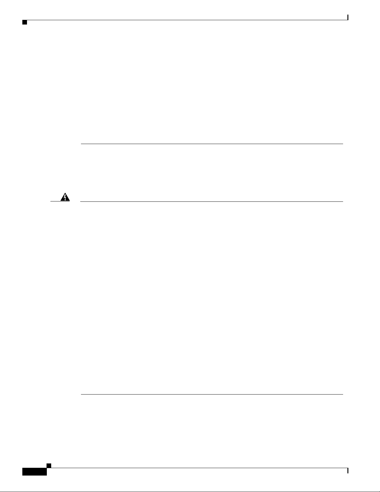
Translated Safety Warnings
Avvertenza
L'eliminazione finale di questo prodotto deve essere eseguita osservando le normative italiane
vigenti in materia.
Advarsel
Aviso
Endelig disponering av dette produktet må skje i henhold til nasjonale lover og forskrifter.
A descartagem final deste produto deverá ser efectuada de acordo com os regulamentos e a
legislação nacional.
¡Advertencia!
El desecho final de este producto debe realizarse según todas las leyes y regulaciones
nacionales.
Varning!
Slutlig kassering av denna produkt bör skötas i enlighet med landets alla lagar och föreskrifter.
Ground Connection Warning
Warning
Waarschuwing
When installing the unit, the ground connection must always be made first and disconnected last.
Bij de installatie van het toestel moet de aardverbinding altijd het eerste worden gemaakt en
het laatste worden losgemaakt.
Varoitus
Attention
Warnung
Avvertenza
Advarsel
Aviso
¡Advertencia!
Varning!
Laitetta asennettaessa on maahan yhdistäminen aina tehtävä ensiksi ja maadoituksen irti
kytkeminen viimeiseksi.
Lors de l’installation de l’appareil, la mise à la terre doit toujours être connectée en premier et
déconnectée en dernier.
Der Erdanschluß muß bei der Installation der Einheit immer zuerst hergestellt und zuletzt
abgetrennt werden.
In fase di installazione dell'unità, eseguire sempre per primo il collegamento a massa e
disconnetterlo per ultimo.
Når enheten installeres, må jordledningen alltid tilkobles først og frakobles sist.
Ao instalar a unidade, a ligação à terra deverá ser sempre a primeira a ser ligada, e a última a
ser desligada.
Al instalar el equipo, conectar la tierra la primera y desconectarla la última.
Vid installation av enheten måste jordledningen alltid anslutas först och kopplas bort sist.
30
Cisco AS5850 Universal Gateway Regulatory Compliance and Safety Information
OL-10265-01
Page 31

Jewelry Removal Warning
Translated Safety Warnings
Warning
Waarschuwing
Varoitus
Attention
Warnung
Avvertenza
Before working on equipment that is connected to power lines, remove jewelry (including rings,
necklaces, and watches). Metal objects will heat up when connected to power and ground and can
cause serious burns or weld the metal object to the terminals.
Alvorens aan apparatuur te werken die met elektrische leidingen is verbonden, sieraden
(inclusief ringen, kettingen en horloges) verwijderen. Metalen voorwerpen worden warm
wanneer ze met stroom en aarde zijn verbonden, en kunnen ernstige brandwonden veroorzaken
of het metalen voorwerp aan de aansluitklemmen lassen.
Ennen kuin työskentelet voimavirtajohtoihin kytkettyjen laitteiden parissa, ota pois kaikki korut
(sormukset, kaulakorut ja kellot mukaan lukien). Metalliesineet kuumenevat, kun ne ovat
yhteydessä sähkövirran ja maan kanssa, ja ne voivat aiheuttaa vakavia palovammoja tai hitsata
metalliesineet kiinni liitäntänapoihin.
Avant d’accéder à cet équipement connecté aux lignes électriques, ôter tout bijou (anneaux,
colliers et montres compris). Lorsqu’ils sont branchés à l’alimentation et reliés à la terre, les
objets métalliques chauffent, ce qui peut provoquer des blessures graves ou souder l’objet
métallique aux bornes.
Vor der Arbeit an Geräten, die an das Netz angeschlossen sind, jeglichen Schmuck
(einschließlich Ringe, Ketten und Uhren) abnehmen. Metallgegenstände erhitzen sich, wenn sie
an das Netz und die Erde angeschlossen werden, und können schwere Verbrennungen
verursachen oder an die Anschlußklemmen angeschweißt werden.
Prima di intervenire su apparecchiature collegate alle linee di alimentazione, togliersi
qualsiasi monile (inclusi anelli, collane, braccialetti ed orologi). Gli oggetti metallici si
riscaldano quando sono collegati tra punti di alimentazione e massa: possono causare ustioni
gravi oppure il metallo può saldarsi ai terminali.
¡Advertencia!
OL-10265-01
Advarsel
Aviso
Varning!
Fjern alle smykker (inkludert ringer, halskjeder og klokker) før du skal arbeide på utstyr som er
koblet til kraftledninger. Metallgjenstander som er koblet til kraftledninger og jord blir svært
varme og kan forårsake alvorlige brannskader eller smelte fast til polene.
Antes de trabalhar em equipamento que esteja ligado a linhas de corrente, retire todas as jóias
que estiver a usar (incluindo anéis, fios e relógios). Os objectos metálicos aquecerão em
contacto com a corrente e em contacto com a ligação à terra, podendo causar queimaduras
graves ou ficarem soldados aos terminais.
Antes de operar sobre equipos conectados a líneas de alimentación, quitarse las joyas
(incluidos anillos, collares y relojes). Los objetos de metal se calientan cuando se conectan a
la alimentación y a tierra, lo que puede ocasionar quemaduras graves o que los objetos
metálicos queden soldados a los bornes.
Tag av alla smycken (inklusive ringar, halsband och armbandsur) innan du arbetar på utrustning
som är kopplad till kraftledningar. Metallobjekt hettas upp när de kopplas ihop med ström och
jord och kan förorsaka allvarliga brännskador; metallobjekt kan också sammansvetsas med
kontakterna.
Cisco AS5850 Universal Gateway Regulatory Compliance and Safety Information
31
Page 32

Translated Safety Warnings
Qualified Personnel Warning
Warning
Waarschuwing
Varoitus
Avertissement
Achtung
Avvertenza
Advarsel
Aviso
¡Atención!
Varning
Only trained and qualified personnel should be allowed to install or replace this equipment.
Installatie en reparaties mogen uitsluitend door getraind en bevoegd personeel uitgevoerd
worden.
Ainoastaan koulutettu ja pätevä henkilökunta saa asentaa tai vaihtaa tämän laitteen.
Tout installation ou remplacement de l'appareil doit être réalisé par du personnel qualifié et
compétent.
Gerät nur von geschultem, qualifiziertem Personal installieren oder auswechseln lassen.
Solo personale addestrato e qualificato deve essere autorizzato ad installare o sostituire questo
apparecchio.
Kun kvalifisert personell med riktig opplæring bør montere eller bytte ut dette utstyret.
Este equipamento deverá ser instalado ou substituído apenas por pessoal devidamente treinado
e qualificado.
Estos equipos deben ser instalados y reemplazados exclusivamente por personal técnico
adecuadamente preparado y capacitado.
Denna utrustning ska endast installeras och bytas ut av utbildad och kvalificerad personal.
Supply Circuit Warning
Warning
Waarschuwing
Varoitus
Avertissement
Achtung
Cisco AS5850 Universal Gateway Regulatory Compliance and Safety Information
32
Care must be given to connecting units to the supply circuit so that wiring is not overloaded.
Let erop dat de toestellen op voedingscircuits worden aangesloten zonder het vermogen van de
bedrading te overschrijden.
Laiteyksiköt on yhdistettävä huolellisesti syöttöpiiriin niin, että johdot eivät ole
ylikuormitettuja.
Veillez à bien connecter les unités au circuit d'alimentation afin de ne pas surcharger les
connections.
Beim Anschließen der Geräte an das Stromnetz ist darauf zu achten, daß die
Schaltverbindungen nicht überlastet werden.
OL-10265-01
Page 33

Translated Safety Warnings
Avvertenza
Fare attenzione quando si collegano le unità al circuito di alimentazione, per non
sovraccaricare i cablaggi.
Advarsel
Aviso
Vær nøye med å koble enheter til strømforsyningskretsen slik at ledningene ikke overbelastes.
Deverá ter precaução ao ligar unidades ao circuito de fornecimento de energia, para não
sobrecarregar a instalação.
¡Atención!
Poner mucho cuidado al conectar los equipos al circuito de alimentación a fin de no
sobrecargar el cableado.
Varning
Var noga vid anslutning av enheter till matarströmkretsen så att ledningarna inte överbelastas.
SELV Circuit Warning
Warning
To avoid electric shock, do not connect safety extra-low voltage (SELV) circuits to
telephone-network voltage (TNV) circuits. LAN ports contain SELV circuits, and WAN ports contain
TNV circuits. Some LAN and WAN ports both use RJ-45 connectors. Use caution when connecting
cables.
Waarschuwing
Varoitus
Attention
Warnung
Avvertenza
Om elektrische schokken te vermijden, mogen veiligheidscircuits met extra lage spanning
(genaamd SELV = Safety Extra-Low Voltage) niet met telefoonnetwerkspanning (TNV) circuits
verbonden worden. LAN (Lokaal netwerk) poorten bevatten SELV circuits en WAN (Regionaal
netwerk) poorten bevatten TNV circuits. Sommige LAN en WAN poorten gebruiken allebei RJ-45
connectors. Ga voorzichtig te werk wanneer u kabels verbindt.
Jotta vältyt sähköiskulta, älä kytke pienjännitteisiä SELV-suojapiirejä puhelinverkkojännitettä
(TNV) käyttäviin virtapiireihin. LAN-portit sisältävät SELV-piirejä ja WAN-portit
puhelinverkkojännitettä käyttäviä piirejä. Osa sekä LAN- että WAN-porteista käyttää
RJ-45-liittimiä. Ole varovainen kytkiessäsi kaapeleita.
Pour éviter une électrocution, ne raccordez pas les circuits de sécurité basse tension (Safety
Extra-Low Voltage ou SELV) à des circuits de tension de réseau téléphonique (Telephone
Network Voltage ou TNV). Les ports du réseau local (LAN) contiennent des circuits SELV et les
ports du réseau longue distance (WAN) sont munis de circuits TNV. Certains ports LAN et WAN
utilisent des connecteurs RJ-45. Raccordez les câbles en prenant toutes les précautions
nécessaires.
Zur Vermeidung von Elektroschock die Sicherheits-Kleinspannungs-Stromkreise (SELV-Kreise)
nicht an Fernsprechnetzspannungs-Stromkreise (TNV-Kreise) anschließen. LAN-Ports enthalten
SELV-Kreise, und WAN-Ports enthalten TNV-Kreise. Einige LAN- und WAN-Ports verwenden
auch RJ-45-Steckverbinder. Vorsicht beim Anschließen von Kabeln.
Per evitare scosse elettriche, non collegare circuiti di sicurezza a tensione molto bassa (SELV)
ai circuiti a tensione di rete telefonica (TNV). Le porte LAN contengono circuiti SELV e le porte
WAN contengono circuiti TNV. Alcune porte LAN e WAN fanno uso di connettori RJ-45. Fare
attenzione quando si collegano cavi.
OL-10265-01
Cisco AS5850 Universal Gateway Regulatory Compliance and Safety Information
33
Page 34

Translated Safety Warnings
Advarsel
Unngå å koble lavspenningskretser (SELV) til kretser for telenettspenning (TNV), slik at du
unngår elektrisk støt. LAN-utganger inneholder SELV-kretser og WAN-utganger inneholder
TNV-kretser. Det finnes både LAN-utganger og WAN-utganger som bruker RJ-45-kontakter. Vær
forsiktig når du kobler kabler.
Aviso
Para evitar choques eléctricos, não conecte os circuitos de segurança de baixa tensão (SELV)
aos circuitos de tensão de rede telefónica (TNV). As portas LAN contêm circuitos SELV e as
portas WAN contêm circuitos TNV. Algumas portas LAN e WAN usam conectores RJ-45. Tenha
o devido cuidado ao conectar os cabos.
¡Advertencia!
Para evitar la sacudida eléctrica, no conectar circuitos de seguridad de voltaje muy bajo (safety
extra-low voltage = SELV) con circuitos de voltaje de red telefónica (telephone network voltage
= TNV). Los puertos de redes de área local (local area network = LAN) contienen circuitos SELV,
y los puertos de redes de área extendida (wide area network = WAN) contienen circuitos TNV.
En algunos casos, tanto los puertos LAN como los WAN usan conectores RJ-45. Proceda con
precaución al conectar los cables.
Varning!
För att undvika elektriska stötar, koppla inte säkerhetskretsar med extra låg spänning
(SELV-kretsar) till kretsar med telefonnätspänning (TNV-kretsar). LAN-portar innehåller
SELV-kretsar och WAN-portar innehåller TNV-kretsar. Vissa LAN- och WAN-portar är försedda
med RJ-45-kontakter. Iaktta försiktighet vid anslutning av kablar.
Hazardous Voltages in WAN Ports
Warning
Waarschuwing
Varoitus
Attention
Warnung
Hazardous network voltages are present in WAN ports regardless of whether power to the router is
OFF or ON. To avoid electric shock, use caution when working near WAN ports. When detaching
cables, detach the end away from the router first.
Er is gevaarlijke netwerkspanning aanwezig in WAN poorten ongeacht of de stroom naar de
router INGESCHAKELD of UITGESCHAKELD is. Om elektrische schokken te vermijden, dient u
voorzichtig te werk te gaan wanneer u in de nabijheid van WAN poorten werkt. Wanneer u
kabels losmaakt, dient u eerst het uiteinde dat zich het verst van de router vandaan bevindt, te
verwijderen.
WAN-porteissa on vaarallisia verkkojännitteitä riippumatta siitä, onko reitittimen virta kytketty
vai ei. Välttyäksesi sähköiskulta ole varovainen työskennellessäsi WAN-porttien lähettyvillä.
Kun irrotat kaapeleita, irrota reitittimestä kauempana sijaitseva pää ensiksi.
Les ports de réseau longue distance (WAN) gèrent des tensions de réseau dangereuses, que le
routeur soit sous tension ou pas. Pour éviter tout risque d’électrocution, prenez toutes les
précautions nécessaires avant de travailler à proximité des ports WAN. Pour déconnecter les
câbles, commencez par débrancher l’extrémité la plus éloignée du routeur.
In WAN-Ports sind gefährliche Netzspannungen vorhanden, auch wenn der Strom zum Router
abgeschaltet wurde. Zur Vermeidung von Elektroschock Vorsicht bei der Arbeit in der Nähe von
WAN-Ports. Beim Abtrennen von Kabeln zuerst das vom Router entfernte Ende lösen.
34
Cisco AS5850 Universal Gateway Regulatory Compliance and Safety Information
OL-10265-01
Page 35

Translated Safety Warnings
Avvertenza
Advarsel
Aviso
¡Advertencia!
Varning!
Nelle porte WAN sono presenti tensioni di rete pericolose, sia che il router sia acceso o meno
(ON od OFF). Per evitare scosse elettriche, fare attenzione quando si lavora in prossimità di
porte WAN. Quando si scollegano cavi, staccare per primo il connettore collegato al router.
Det er livsfarlig nettverksspenning i WAN-utganger, uavhengig av om strømmen til
fordelingsenheten er slått av (OFF) eller på (ON). Vær forsiktig når du jobber nær WAN-utganger
slik at du unngår elektrisk støt. Hvis du skal løsne kabler, må du først løsne den enden som er
lengst borte fra fordelingsenheten.
Existem sempre tensões de rede perigosas nas portas WAN, independentemente da corrente
para o dispositivo repartidor de mensagens estar ligada (ON) ou desligada (OFF). Para evitar
choques eléctricos, tenha o devido cuidado ao trabalhar perto das portas WAN. Ao desconectar
os cabos, separe primeiro a extremidade que se encontra ligada ao dispositivo repartidor de
mensagens.
Hay tensiones de red peligrosas en los puertos de redes de área extendida (WAN), tanto con la
alimentación al router conectada como desconectada. Para evitar la sacudida eléctrica,
proceda con precaución cuando trabaje en las proximidades de puertos WAN. Para
desconectar los cables, desconecte primero el extremo que va al router.
Farlig nätverksspänning föreligger i WAN-portarna oavsett om strömförsörjningen till
distributören är bruten eller ej. För att undvika elektriska stötar ska du vara försiktig vid arbete
i närheten av dessa portar. När du kopplar bort en kabel ska du först koppla bort den ände som
inte är ansluten till distributören.
Incorrect Connection Warning
Warning
Waarschuwing
Varoitus
Attention
Warnung
Avvertenza
Advarsel
Incorrect connection of this or connected equipment to a general purpose outlet could result in a
hazardous situation.
Incorrecte aansluiting van deze of aangesloten apparatuur op een stopcontact voor algemene
doeleinden kan een gevaarlijke situatie tot gevolg hebben.
Tämän laitteen tai siihen liitettyjen laitteiden virheellinen kytkentä yleispistorasiaan voi
aiheuttaa vaaratilanteen.
Un branchement incorrect de cet équipement ou de l’équipement branché à une prise d’usage
général peut créer une situation dangereuse.
Inkorrektes Anschließen von diesem oder damit verbundenen Geräten an einer
Allzwecksteckdose kann eine Gefahrensituation verursachen.
Un collegamento errato di questo apparecchio, o dell’apparecchiatura a esso collegato, a una
presa di uso generale può causare una situazione pericolosa.
Feil kobling av dette utstyret eller tilhørende utstyr til et vanlig uttak kan føre til farlige
situasjoner.
OL-10265-01
Cisco AS5850 Universal Gateway Regulatory Compliance and Safety Information
35
Page 36

Translated Safety Warnings
Aviso
Uma conexão incorrecta a uma ficha de alimentação eléctrica normal, deste ou de qualquer
equipamento a este conectado, poderá resultar numa situação potencialmente perigosa.
¡Advertencia!
La conexión incorrecta de este equipo, o del equipo conectado, a una toma o receptáculo de tipo
general podría resultar en una situación peligrosa.
Varning!
Felaktig koppling av denna eller ansluten utrustning till ett universaluttag kan orsaka riskfylld
situation.
SELV Circuit Warning
Warning
Waarschuwing
The ports labeled "Network Clock," "10BASE-T," "Dial Shelf Interconnect," "Console," and "Alarms"
are safety extra-low voltage (SELV) circuits. SELV circuits should only be connected to other SELV
circuits. Because the E1/T1 circuits are treated like telephone-network voltage, avoid connecting
the SELV circuit to the telephone network voltage (TNV) circuits.
De poorten die gelabeld zijn met "Network Clock," "10BASE-T," "Dial Shelf Interconnect,"
Console" en "Alarms" zijn veiligheidscircuits met extra-laag voltage (SELV). SELV-circuits
mogen alleen met andere SELV-circuits worden verbonden. Omdat de E1/T1 circuits behandeld
worden als telefoonnetwerk-voltage, dient u SELV-circuits niet aan telefoonnetwerk-voltages
(TNV) aan te sluiten.
Varoitus
Avertissement
Warnung
Avvertenza
Portit, joissa on merkintä "Network Clock" (Verkkokello), "10BASE-T", "Dial Shelf Interconnect"
(Valintahyllyn liitäntä), "Console" (Konsoli) ja "Alarms" (Hälytykset) ovat suojattuja erittäin
alhaisen jännitteen (SELV) piirejä. SELV-piirit tulisi liittää ainoastaan toisiin SELV-piireihin.
Les ports portant les libellés « Network Clock » (horloge réseau), « 10BASE-T », « Dial Shelf
Interconnect » (interconnexion de plateau de commutation), « Console » et « Alarms » sont des
circuits à tension extra-basse de sécurité SELV (Safety Extra-Low Voltage). Les circuits SELV
doivent être connectés uniquement à d’autres circuits SELV. Les circuits E1/T1 étant traités
comme des connexions à tension de réseau téléphonique, évitez de connecter le circuit SELV
aux circuits de ce type de réseau.
Die Anschlüsse mit den Bezeichnungen "Network Clock", "10BASE-T", "Dial Shelf Interconnect",
"Console" und "Alarms" sind Sicherheitsschaltungen mit Niedrigspannung (SELV).
SELV-Schaltungen dürfen nur mit anderen SELV-Schaltungen verbunden werden. Da
E1/T1-Schaltungen wie Schaltungen mit Telefon-Netzspannung (TNV) behandelt werden, ist das
Anschlaten von SELV- an TNV-Schaltungen zu verbinden.
Le porte etichettate "Network Clock", "10BASE-T", "Dial Shelf Interconnect", "Console" e
"Alarms" sono dei circuiti di sicurezza a bassissima tensione (SELV). I circuiti SELV possono
essere collegati unicamente ad altri circuiti SELF. Siccome i circuiti E1/T1 sono trattati come
delle connessioni a tensione di rete telefonica (TNV), evitare di collegare il circuito SELV ai
circuiti TNV.
36
Cisco AS5850 Universal Gateway Regulatory Compliance and Safety Information
OL-10265-01
Page 37

Translated Safety Warnings
Advarsel!
Utgangene merket "Network Clock", "10BASE-T", "Dial Shelf Interconnect", "Console" og
"Alarms" er sikkerhetskretser (SELV) med veldig lav spenning. SELV-kretser skal bare kobles til
andre SELV-kretser. Fordi E1/T1-kretser behandles som telefonnettspenning, skal SELV-kretsen
ikke kobles til kretser for telefonnettspenning (TNV).
Aviso
As portas rotuladas "Network Clock", "10BASE-T", "Dial Shelf Interconnect", "Console" e
"Alarms" são circuitos de tensão extrema inferior de segurança (SELV). Os circuitos SELV só
devem ser conectados a outros circuitos SELV. Como os circuitos E1/T1 são tratados como a
tensão da rede telefónica, evite conectar o circuito SELV aos circuitos da tensão da rede
telefónica (TNV).
¡Advertencia!
Los puertos con las etiquetas "Network Clock", "10BASE-T", "Dial Shelf Interconnect", "Console"
y "Alarms" son circuitos de seguridad de muy bajo voltaje (Safety Extra-Low Voltage, SELV).
Estos circuitos sólo deben conectarse a otros circuitos SELV. Debido a que los circuitos E1/T1
se tratan igual que el voltaje de la red telefónica, evite conectar el circuito SELV a los circuitos
de voltaje de la red telefónica (Telephone Network Voltage, TNV).
Varning!
Portarna med beteckningen "Network Clock", "10BASE-T", "Dial Shelf Interconnect", "Console"
och "Alarms" är SELV-kretsar (skyddskretsar för mycket låg spänning). SELV-kretsar ska endast
kopplas till andra SELV-kretsar. Undvik att koppla SELV-kretsen till kretsar med
telefonnätsspänning (TNV) eftersom E1-/T1-kretsar betraktas som telefonnätsspänning.
Power Cord Warning
Warning
Waarschuwing
Varoitus
Attention
Warnung
Avvertenza
Advarsel
This unit has more than one power cord. To reduce the risk of electric shock, disconnect the three
to five power supply cords before servicing the unit.
Dit toestel heeft meer dan één netsnoer. Om het risico van een elektrische schok te verminderen,
dient u de stekkers van de drie à vijf netsnoeren uit het stopcontact te halen voordat u het toestel
een servicebeurt geeft.
Tässä yksikössä on useampi kuin yksi liitäntäjohdin. Irrota virtalähteestä tulevat kolmesta
viiteen johdinta ennen laitteen huoltamista, jotta vältät sähköiskun vaaran.
Cet appareil est muni de plusieurs cordons d’alimentation. Afin de réduire le risque
d’électrocution, débrancher les trois à cinq cordons d’alimentation avant de procéder à
l’entretien ou au dépannage de l’appareil.
Diese Einheit hat mehr als ein Netzkabel. Zur Verringerung der Stromschlaggefahr trennen Sie
die drei bis fünf Netzgerätekabel ab, bevor Sie die Einheit warten.
Questo apparecchio ha più di un cavo di alimentazione (da tre a cinque). Per ridurre il rischio
di scosse elettriche, prima di procedere alla manutenzione dell’apparecchio scollegare tutti i
cavi di alimentazione.
Denne enheten har mer enn én strømledning. Kople fra de tre til fem strømledningene før du
vedlikeholder enheten, slik at du reduserer faren for elektrisk støt.
OL-10265-01
Cisco AS5850 Universal Gateway Regulatory Compliance and Safety Information
37
Page 38

Translated Safety Warnings
Aviso
Esta unidade tem mais de um cabo de alimentação. Para reduzir o risco de choque eléctrico,
desligue os três a cinco cabos de alimentação antes de efectuar reparações na unidade.
¡Advertencia!
Esta unidad posee más de un cable de alimentación. Para reducir el riesgo de descarga
eléctrica, desenchufar los tres (o cuatro o cinco) cables antes de proceder al mantenimiento de
la unidad.
Varning!
Denna enhet har mer än en nätsladd. För att minska risken för elektriska stötar skall de tre till
fem nätsladdarna dras ur innan du utför underhållsarbete på enheten.
Service Personnel Warning
Warning
Waarschuwing
Varoitus
This equipment is to be installed and maintained by service personnel only as defined by AS/NZS
3260 Clause 1.2.14.3 Service Personnel.
Deze apparatuur mag slechts geïnstalleerd en onderhouden worden door servicepersoneel
conform de definitie van AS/NZS 3260 Clausule 1.2.14.3 Service Personnel.
Tämän laitteen saa asentaa tai huoltaa ainoastaan Australiassa ja Uudessa Seelannissa
sovellettavan AS/NZS 3260 -standardin kohdan 1.2.14.3 Service Personnel määrittelemä
huoltohenkilöstö.
Attention
Warnung
Avvertenza
Advarsel
Aviso
¡Advertencia!
Varning!
Cet équipement ne doit être installé et entretenu que par du personnel d’entretien comme défini
par la réglementation AS/NZS 3260 Clause 1.2.14.3 Service Personnel.
Dieses Gerät darf nur von Wartungspersonal gemäß AS/NZS-Definition 3260, Paragraph 1.2.14.3,
"Service Personnel", installiert und gewartet werden.
Questo apparecchio deve essere installato e mantenuto in efficienza esclusivamente da
personale tecnico che soddisfi i requisiti specificati nella sezione 1.2.14.3 sul ‘Service
Personnel’ contenuta nelle norme AS/NZS 3260.
Installasjon og vedlikehold av dette utstyret skal kun foretas av vedlikeholdspersonell som
definert i AS/NZS 3260, klausul 1.2.14.3 Service Personnel.
Este equipamento deverá ser instalado e reparado apenas por pessoal de manutenção
qualificado, conforme estipulado em AS/NZS 3260 Cláusula 1.2.14.3 Service Personnel.
Este equipo se debe instalar y mantener solamente por personal de servicio, según definido por
AS/NZS 3260 Cláusula 1.2.14.3 Service Personnel.
Installation och underhåll av denna utrustning får endast utföras av servicepersonal enligt
definition i AS/NZS 3260 klausul 1.2.14.3 Service Personnel.
38
Cisco AS5850 Universal Gateway Regulatory Compliance and Safety Information
OL-10265-01
Page 39

Telecommunications Lines Warning
Translated Safety Warnings
Warning
Waarschuwing
Varoitus
Attention
Warnung
Avvertenza
Advarsel
Aviso
The telecommunications lines must be disconnected 1) before unplugging the main power
connector and/or 2) while the housing is open.
De telecommunicatielijnen moeten verbroken worden 1) voordat de hoofdvoedingsconnector
uitgeschakeld wordt en/of 2) terwijl de behuizing nog open is.
Tietoliikennelinjat on kytkettävä irti 1) ennen kuin päävirtaliitin irrotetaan pistorasiasta ja/tai
2) kun suojus on auki.
Les lignes de télécommunications doivent être déconnectées 1) avant de débrancher le
connecteur d’alimentation principal et/ou 2) lorsque le boîtier est ouvert.
Die Fernmeldeleitungen müssen getrennt werden, 1) bevor der Netzstecker abgezogen wird
und/oder 2) während das Gehäuse geöffnet ist.
Le linee di telecomunicazione vanno scollegate sia prima di scollegare la spina
dell’alimentazione di rete sia prima di aprire l’involucro (non ricollegarle finché non si chiude
l’involucro).
Telekommunikasjonsledningene må være frakoblet 1) før hovedstrømskoblingen kobles ut
og/eller 2) når huset er åpent.
As linhas de telecomunicações têm de ser desligadas: 1) antes de desligar o conector de
corrente principal; e/ou 2) enquanto a cobertura estiver aberta.
¡Advertencia!
Varning!
Las líneas de telecomunicaciones deben desconectarse 1) antes de desenchufar el conector
principal de energía y 2) mientras la caja esté abierta.
Telekommunikationslinjerna måste vara urkopplade 1) innan huvudströmskontakten tas ur
och/eller 2) medan kåpan är öppen.
OL-10265-01
Cisco AS5850 Universal Gateway Regulatory Compliance and Safety Information
39
Page 40

Translated Safety Warnings
Customer Equipment Warning
Warning
Waarschuwing
Varoitus
Attention
The E1 interface card may only be installed in an ACA-permitted customer equipment or a Data
Terminal Equipment (DTE) that is exempted from ACA's permit requirements. The customer
equipment must only be housed in a cabinet that has screw-down lids to stop user access to
overvoltages on the customer equipment. The customer equipment has circuitry that may have
telecommunications network voltages on them.
De E1-interfacekaart mag slechts geïnstalleerd worden in door ACA toegestane apparatuur van
de klant of in Data Terminal Equipment (DTE) die vrijgesteld is van de vergunningsvereisten van
ACA. De apparatuur van de klant moet in een kastje geplaatst worden met sluitplaten die
dichtgeschroefd kunnen worden om te voorkomen dat de gebruiker toegang verkrijgt tot
overspanning op de apparatuur van de klant. De apparatuur van de klant heeft een
schakelsysteem waarop telecommunicatienetwerkspanning kan staan.
E1-liitäntäkortin saa asentaa ainoastaan ACA:n hyväksymiin asiakaslaitteisiin tai Data
Terminal Equipment -laitteisiin (DTE), jotka eivät kuulu ACA:n lupavaatimusten piiriin.
Asiakaslaitteet on sijoitettava koteloon, jossa on kiinni ruuvattavat kannet, jotta käyttäjä ei
altistu asiakaslaitteiden ylijännitteille. Asiakaslaitteissa on virtapiiri, jossa voi olla
tietoliikenneverkkojännitteitä.
La carte d’interface E1 ne peut être installée que dans un équipement de l’utilisateur autorisé
par ACA ou dans un DTE (Data Terminal Equipment) pour lequel l’autorisation de ACA n’est pas
exigée. L’équipement de l’utilisateur ne doit être placé que dans une enceinte munie de
couvercles à vis qui empêchent l’utilisateur d’accéder aux surtensions présentes. L’équipement
de l’utilisateur est muni de circuits qui peuvent avoir des tensions de réseau de
télécommunications.
Warnung
Avvertenza
Advarsel
Die E1-Schnittstellenkarte darf nur in einer von der Australian Communications Authority (ACA)
zugelassenen Teilnehmereinrichtung oder einer von den ACA-Zulassungsanforderungen
ausgenommenen Datenendeinrichtung (DEE) installiert werden. Die Teilnehmereinrichtung muß
in einem Gehäuse untergebracht sein, das mit Aufschraubdeckeln versehen ist, um den Zugang
der Benutzer zu Überspannungen an der Teilnehmereinrichtung zu verhindern. In der
Teilnehmereinrichtung befinden sich Schaltkreise, an denen möglicherweise
Fernmeldenetzspannungen anliegen.
La scheda d’interfaccia E1 può essere installata solo in un’apparecchiatura con autorizzazione
ACA o in un ‘Data Terminal Equipment (DTE)’ esente dai requisiti per l’autorizzazione ACA. La
suddetta apparecchiatura deve essere contenuta in un armadio con coperchi bloccabili con viti,
per impedire l’accesso alle sovratensioni in essa presenti; i suoi circuiti possono essere a
tensioni di rete di telecomunicazioni.
Grensesnittkortet E1 kan kun installeres i kundeutstyr som er godkjent av ACA, eller i
dataterminalutstyr (DTE) som er unndratt ACAs krav til tillatelse. Kundeutstyret må kun være
plassert i et kabinett som har lokk som er skrudd fast, for å hindre brukertilgang til overspenning
på kundeutstyret. Kundeutstyret inneholder kretser som kan ha nettverksspenning for
telekommunikasjon.
40
Cisco AS5850 Universal Gateway Regulatory Compliance and Safety Information
OL-10265-01
Page 41

Translated Safety Warnings
Aviso
O cartão de ligação E1 apenas poderá ser instalado em equipamento dos clientes que possuam
autorização da ACA (Australian Communications Authority) ou num DTE (Data Terminal
Equipment), que esteja isento dos requisitos de autorização da ACA. O equipamento dos clientes
deverá ser somente colocado numa caixa com tampas de aparafusar, para impossibilitar o
acesso do utilizador às altas tensões deste mesmo equipamento. O equipamento do cliente
possui circuitos que poderão ter tensões de rede de telecomunicações.
¡Advertencia!
La tarjeta de interfaz E1 sólo se puede instalar en un equipo de cliente permitido por ACA o en
un equipo de terminal de datos (DTE) que no requiera el permiso de ACA. El equipo del cliente
sólo debe estar instalado en un armario con cubiertas atornilladas, para evitar el acceso del
usuario a los sobrevoltajes presentes en dicho equipo. El equipo del cliente tiene circuitos
donde pueden estar presentes voltajes de la red de telecomunicaciones.
Varning!
E1-gränssnittskortet får endast installeras i en av ACA tillåten kundutrustning eller en Data
Terminal Equipment (DTE) som är undantagen ACA:s licenskrav. Kundutrustningen måste vara i
ett skåp med igenskruvade lock som hindrar användaren från att komma åt överspänning på
kundutrustningen. Det finns kretsar i kundutrustningen som kan ha nätverksspänning.
No. 26 AWG Warning
Warning
Waarschuwing
Varoitus
Attention
Warnung
Avvertenza
Advarsel
Aviso
To reduce the risk of fire, use only No. 26 AWG or larger telecommunication line cord.
Om brandgevaar te reduceren, dient slechts telecommunicatielijnsnoer nr. 26 AWG of groter
gebruikt te worden.
Tulipalovaaran vähentämiseksi käytä ainoastaan nro 26 AWG- tai paksumpaa
tietoliikennejohdinta.
Pour réduire le risque d’incendie, n’utiliser que des cordons de lignes de télécommunications
de type AWG nº 26 ou plus larges.
Zur Reduzierung der Feuergefahr eine Fernmeldeleitungsschnur der Größe 26 AWG oder größer
verwenden.
Per ridurre il rischio di incendio, usare solo un cavo per linea di telecomunicazioni di sezione
0,12 mm
2
(26 AWG) o maggiore.
Bruk kun AWG nr. 26 eller telekommunikasjonsledninger med større dimensjon for å redusere
faren for brann.
Para reduzir o risco de incêndio, utilize apenas terminais de fio de telecomunicações Nº. 26
AWG ou superiores.
OL-10265-01
Cisco AS5850 Universal Gateway Regulatory Compliance and Safety Information
41
Page 42

Translated Safety Warnings
¡Advertencia!
Para reducir el riesgo de incendios, usar sólo líneas de telecomunicaciones de calibre No. 26
AWG o más gruesas.
Varning!
För att minska brandrisken skall endast Nr. 26 AWG eller större telekommunikationsledning
användas.
Ground Conductor Warning
Warning
Waarschuwing
Varoitus
Never defeat the ground conductor or operate the equipment in the absence of a suitably installed
ground conductor. Contact the appropriate electrical inspection authority or an electrician if you
are uncertain that suitable grounding is available.
De aardingsleiding mag nooit buiten werking gesteld worden en de apparatuur mag nooit
bediend worden zonder dat er een op de juiste wijze geïnstalleerde aardingsleiding aanwezig
is. Neem contact op met de bevoegde instantie voor elektrische inspecties of met een
elektricien als u er niet zeker van bent dat er voor passende aarding gezorgd is.
Älä koskaan ohita maajohdinta tai käytä laitteita ilman oikein asennettua maajohdinta. Ota
yhteyttä asianmukaiseen sähkötarkastusviranomaiseen tai sähköasentajaan, jos olet epävarma
maadoituksen sopivuudesta.
Attention
Warnung
Avvertenza
Advarsel
Aviso
Ne jamais rendre inopérant le conducteur de masse ni utiliser l’équipement sans un conducteur
de masse adéquatement installé. En cas de doute sur la mise à la masse appropriée disponible,
s’adresser à l’organisme responsable de la sécurité électrique ou à un électricien.
Auf keinen Fall den Erdungsleiter unwirksam machen oder das Gerät ohne einen sachgerecht
installierten Erdungsleiter verwenden. Wenn Sie sich nicht sicher sind, ob eine sachgerechte
Erdung vorhanden ist, wenden Sie sich an den zuständigen elektrischen Fachmann oder einen
Elektriker.
Non escludere mai il conduttore di protezione né usare l’apparecchiatura in assenza di un
conduttore di protezione installato in modo corretto. Se non si sa con certezza che è disponibile
un collegamento di messa a terra adeguato, esaminare le Norme CEI pertinenti o rivolgersi a un
elettricista qualificato.
Omgå aldri jordingslederen og bruk aldri utstyret uten riktig montert jordingsleder. Ta kontakt
med det riktige organet for elektrisk inspeksjon eller en elektriker hvis du er usikker på om det
finnes velegnet jording.
Nunca anule o condutor à terra nem opere o equipamento sem ter um condutor à terra
adequadamente instalado. Em caso de dúvida em relação ao sistema de ligação à terra,
contacte os serviços locais de inspecção eléctrica ou um electricista qualificado.
42
Cisco AS5850 Universal Gateway Regulatory Compliance and Safety Information
OL-10265-01
Page 43

Translated Safety Warnings
¡Advertencia!
No inhabilitar nunca el conductor de tierra ni hacer funcionar el equipo si no existe un
conductor de tierra instalado correctamente. Póngase en contacto con una autoridad apropiada
de inspección eléctrica o con un electricista competente si no está seguro de que hay una
conexión a tierra adecuada.
Varning!
Koppla aldrig från jordledningen och använd aldrig utrustningen utan en på lämpligt sätt
installerad jordledning. Om det föreligger osäkerhet huruvida lämplig jordning finns skall
elektrisk besiktningsauktoritet eller elektriker kontaktas.
Chassis Power Connection
Warning
Waarschuwing
Before connecting or disconnecting ground or power wires to the chassis, ensure that power is
removed from the DC circuit. To ensure that all power is OFF, locate the circuit breaker on the panel
board that services the DC circuit, switch the circuit breaker to the OFF position, and tape the
switch handle of the circuit breaker in the OFF position.
Voordat u aarddraden of elektriciteitsdraden op het frame aansluit of van het frame neemt, dient
u te controleren of de stroom naar het gelijkstroomcircuit uitgeschakeld is. Om u ervan te
verzekeren dat alle stroom UIT is geschakeld, kiest u op het schakelbord de stroomverbreker
die het gelijkstroomcircuit bedient, draait de stroomverbreker naar de UIT positie en plakt de
schakelaarhendel van de stroomverbreker met plakband in de UIT positie vast.
Varoitus
Attention
Warnung
Avvertenza
Advarsel
Varmista, että tasavirtapiirissä ei ole virtaa ennen maadoitus- tai virtajohtojen kytkemistä
asennuspohjaan tai ennen niiden irrottamista. Varmistaaksesi, että virta on KATKAISTU täysin,
paikanna tasavirrasta huolehtivassa kojetaulussa sijaitseva suojakytkin, käännä suojakytkin
KATKAISTU-asentoon ja teippaa suojakytkimen varsi niin, että se pysyy KATKAISTU-asennossa.
Avant de connecter ou de déconnecter les câbles d'alimentation (pôles et terre) du châssis,
vérifiez que le circuit de courant continu est hors tension : localisez le disjoncteur sur le
panneau de commande du circuit de courant continu, poussez-le sur la position fermée (OFF) et,
à l'aide d'un ruban adhésif, bloquez sa poignée sur cette position.
Gleichstrom-Unterbrechung Bevor Sie Erdungs- oder Stromkabel an das Chassis anschließen
oder von ihm abtrennen, ist sicherzustellen, daß der Gleichstrom-Stromkreis unterbrochen ist.
Um sicherzustellen, daß sämtlicher Strom AUS ist, machen Sie auf der Schalttafel den
Unterbrecher für die Gleichstromschaltung ausfindig, stellen Sie den Unterbrecher auf OFF, und
kleben Sie den Schaltergriff des Unterbrechers mit Klebeband in der AUS-Stellung fest.
Prima di collegare o distaccare i cavi elettrici o di messa a terra dallo chassis, assicuratevi che
il circuito DC non sia alimentato. Per verificare che tutta l'alimentazione sia scollegata (OFF),
individuare l'interruttore automatico sul quadro strumenti che alimenta il circuito CC, mettere
l'interruttore in posizione OFF e fissarlo con nastro adesivo in tale posizione.
Før til- eller frakobling av jord- og strømledninger til kabinettet, kontroller at strømmen er
frakoblet likestrømkretsen. Sørg for at all strøm er slått AV. Dette gjøres ved å lokalisere
strømbryteren på brytertavlen som betjener likestrømkretsen, slå strømbryteren AV og teipe
bryterhåndtaket på strømbryteren i AV-stilling.
OL-10265-01
Cisco AS5850 Universal Gateway Regulatory Compliance and Safety Information
43
Page 44
Translated Safety Warnings
Aviso
Antes de conectar ou desconectar a ligação à terra ou a alimentação do chassis, certifique-se
de que desligou a fonte de alimentação de energia do circuito de corrente contínua. Para se
assegurar que toda a corrente foi DESLIGADA, localize o disjuntor no painel que serve o circuito
de corrente contínua e coloque-o na posição OFF (Desligado), segurando nessa posição a
manivela do interruptor do disjuntor com fita isoladora.
¡Advertencia!
Antes de conectar o desconectar el circuito de tierra o de alimentación del chasis, asegúrese
que la alimentación del circuito CC esté cortada (OFF). Para asegurarse de que toda la
alimentación esté cortada (OFF), localice el interruptor automático en el panel que alimenta el
circuito de corriente continua, cambie el interruptor automático a la posición de apagado (OFF)
y sujete con cinta la palanca del interruptor automático en posición de apagado (OFF).
Varning!
Innan du kopplar jord- eller elledningar till eller från chassit måste du kontrollera att
strömförsörjningen till likströmskretsen är bruten. Kontrollera att all strömförsörjning är
BRUTEN genom att slå AV det överspänningsskydd som skyddar likströmskretsen och tejpa fast
överspänningsskyddets omkopplare i FRÅN-läget.
Card Handling Warning
Warning
High-performance devices on this card can get hot during operation. To remove the card, hold it by
the faceplate and bottom edge. Allow the card to cool before touching any other part of it or before
placing it in an antistatic bag.
Waarschuwing
Varoitus
Attention
Warnung
Avvertenza
Geavanceerde onderdelen op deze kaart kunnen tijdens het gebruik heet worden. Als u de kaart
wilt verwijderen, moet u deze vastpakken bij de voorkant en onderrand. Laat de kaart afkoelen
voordat u andere delen van de kaart aanraakt of voordat u de kaart in een antistatische
verpakking plaatst.
Tämän kortin suorituskykyiset mekanismit voivat kuumeta käytössä. Kortin voi poistaa
tarttumalla siihen tasopinnasta ja alareunasta. Anna kortin jäähtyä, ennen kuin kosket sen
muihin osiin tai ennen kuin laitat sen antistaattiseen pussiin.
Les périphériques hautes performances de cette carte emmagasinent de la chaleur en cours de
fonctionnement. Pour retirer la carte, tenez-la par le cache et par la partie inférieure. Attendez
qu’elle refroidisse avant de toucher les autres parties ou avant de la mettre dans un sac
antistatique.
Hochleistungsgeräte auf dieser Karte können während des Betriebs sehr heiß werden. Um die
Karte zu entfernen, halten Sie sie an der Frontplatte und der Unterkante. Lassen Sie die Karte
abkühlen, bevor Sie sie an einer anderen Stelle berühren oder in einen Antistatikbehälter
stecken.
Le apparecchiature ad alte prestazioni montati su questa scheda possono surriscaldarsi
durante il funzionamento. Per rimuovere la scheda, tenerla tra la piastra anteriore e il bordo
inferiore. Attendere che la scheda si raffreddi prima di toccare le altre componenti o di porla in
un sacchetto antistatico.
44
Cisco AS5850 Universal Gateway Regulatory Compliance and Safety Information
OL-10265-01
Page 45

United States
Advarsel
Aviso
¡Advertencia!
Varning!
Enkelte høykapasitets komponenter på dette kortet kan bli varme under bruk. Hvis du skal ta ut
kortet, må du holde i kortet ved frontplaten og den nederste kanten. La kortet bli avkjølt før du
tar på andre deler av kortet eller putter det i en antistatisk pose.
Os dispositivos de alta performance nesta placa podem aquecer durante o funcionamento. Para
retirar a placa, segure-a pela borda do prato e da base. Deixe a placa arrefecer antes de tocar
em qualquer outra zona da mesma ou antes de a colocar num saco antiestático.
Los dispositivos de alto rendimiento contenidos en la tarjeta pueden alcanzar elevadas
temperaturas durante su funcionamiento. Para extraer la tarjeta, sujétela por el extremo inferior
y la cubierta. Permita que se enfríe la tarjeta antes de tocar ninguna pieza de la misma y de
colocarla en una bolsa antiestática.
Detta korts högprestandaenheter kan bli mycket varma under drift. Ta ut kortet genom att hålla
det på frontpanelen och nedre kanten. Låt kortet svalna innan du vidrör någon annan del av det
eller innan du placerar det i en antistatisk påse.
United States
FCC Registration and Requirements
The following paragraphs describe requirements and information based on FCC rules.
FCC Rules, Part 15
This equipment has been tested and found to comply with the limits for a Class A digital device, pursuant
to Part 15 of the FCC Rules. These limits are designed to provide reasonable protection against harmful
interference when the equipment is operated in a commercial environment. This equipment generates,
uses, and can radiate radio frequency energy and, if not installed and used in accordance with the
instruction manual, may cause harmful interference to radio communications. Operation of this
equipment in a residential area is likely to cause harmful interference, in which case users are required
to correct the interference at their own expense.
Modifying the equipment without Cisco's authorization may result in the equipment no longer
complying with FCC requirements for Class A digital devices. In that event, your right to use the
equipment may be limited by FCC regulation and you may be required to correct any interference to
radio or television communication at your own expense. You can determine whether your equipment is
causing interference by turning it off. If the interference stops, it was probably caused by the Cisco
equipment or one of its peripheral devices. If the equipment causes interference to radio or television
reception, try to correct the interference by using one or more of the following measures:
• Turn the television or radio antenna until the interference stops.
• Move the equipment to one side or the other of the television or radio.
• Move the equipment farther away from the television or radio.
• Plug the equipment into an outlet that is on a different circuit from the television or radio. (That is,
make certain the equipment and the television or radio are on circuits controlled by different circuit
breakers or fuses.)
OL-10265-01
Cisco AS5850 Universal Gateway Regulatory Compliance and Safety Information
45
Page 46

FCC Registration and Requirements
FCC Rules, Part 68
1. FCC Part 68 Registration
The Cisco AS5850 System complies with FCC Rules, Part 68. On the cover of this equipment is a
label that contains, among other information, the FCC Part 68 registration number.
2. Service
In the event of equipment malfunction, all repairs should be performed by Cisco Systems or an
authorized agent. It is the responsibility of users requiring service to report the need for service to
Cisco Systems or to one of our authorized agents. Service can be facilitated through our office at:
Cisco Systems, Inc.
170 West Tasman Drive
San Jose, CA 95134-4567
Telephone: (408) 526-4000
The telephone company can ask you to disconnect the equipment from the network until the problem
is corrected or until you are sure that the equipment is not malfunctioning.
3. Facility Interface Information
In order to connect registered terminal equipment to the telephone company lines, the terminal
equipment must utilize FCC registered jacks. Standardized jacks are used for this equipment.
Table 3 contains Digital Interface Code (DIC), Service Order Code (SOC), and network information
for the equipment.
Table 3 DIC, SOC, and Network Jack Information
Manufacturer
Port Identifier
Digital Interface Code
(DIC)
Service Order Code
(SOC) Network Jack
T1 Interface 04DU9-BN 6.0Y RJ48C
04DU9-DN 6.0Y RJ48C
04DU9-1KN 6.0Y RJ48C
04DU9-1SN 6.0Y RJ48C
4. Disruption of the Network
If the Cisco AS5850 disrupts the telephone network, the telephone company can discontinue your
service temporarily. If possible, the telephone company will notify you in advance. If advance notice
is not practical, they will notify you as soon as possible. You are also informed of your right to file
a complaint with the FCC.
5. Telephone Company Facility Changes
The telephone company can make changes in its facilities, equipment, operations, or procedures that
can affect the operation of your equipment. If they do, you should be notified in advance so you have
an opportunity to maintain uninterrupted telephone service.
6. Electrical Safety Advisory
While the Cisco AS5850 is fully compliant with FCC rules and regulations, it is recommended that
an alternating current (AC) surge arrester of the form and capability suitable for the model
purchased be installed in the AC outlet to which the Cisco AS5850 is connected. Consult with your
distributor for the correct surge protector requirements for your equipment.
46
Cisco AS5850 Universal Gateway Regulatory Compliance and Safety Information
OL-10265-01
Page 47

FCC Registration and Requirements
7. Terminal Attachments
Cisco Systems AS5850 with the interface card AS58-24CT1 bearing labeling identification number
US:5B1DDNAN0001 complies with the Federal Communications Commission’s (“FCC”) Rules
and Regulations 47 CFR Part 68, and the Administrative Council on Terminal Attachments
(“ACTA”) adopted technical criteria:TIA/EIA/IS-968, Technical Criteria for Terminal
Equipment to Prevent Harms to the Telephone Network, July 2001. See Figure 4 for Cisco's
Supplier Declaration of Conformity. This document is also available online at:
http://www.cisco.com/warp/customer/508/dofc/139345.pdf
OL-10265-01
Cisco AS5850 Universal Gateway Regulatory Compliance and Safety Information
47
Page 48

FCC Registration and Requirements
Figure 4 Cisco’s Supplier Declaration of Conformity
48
Cisco AS5850 Universal Gateway Regulatory Compliance and Safety Information
OL-10265-01
Page 49

Canada
English Statement of Compliance
This class A digital apparatus complies with Canadian ICES-003.
French Statement of Compliance
Cet appareil numérique de la classe A est conforme à la norme NMB-003 du Canada.
Industry Canada Compliance.
The following are notices required by Industry Canada Terminal Attachment Program Certification
Procedure CP-01, Part I, Section 14.
Equipment Attachment Limitations
Canada
Europe (EU)
The Industry Canada label identifies certified equipment. This certification means that the equipment
meets certain telecommunications network protective operational and safety requirements. The
Department does not guarantee the equipment will operate to the user's satisfaction.
Before installing the equipment, users should ensure that it is permissible to be connected to the facilities
of the local telecommunications company. The equipment must also be installed using an acceptable
method of connection. In some cases, the company's inside wiring associated with a single line
individual service may be extended by means of a certified connector assembly (telephone extension
cord). The customer should be aware that compliance with the above conditions may not prevent
degradation of service in some situations.
Repairs to certified equipment should be made by an authorized Canadian maintenance facility
designated by the supplier. Any repairs or alterations made by the user to this equipment, or equipment
malfunctions, may give the telecommunications company cause to request the user to disconnect the
equipment.
Users should ensure for their own protection that the electrical ground connections of the power utility,
telephone lines and internal metallic water pipe system, if present, are connected together. This
precaution may be particularly important in rural areas.
This apparatus complies with EN55022 Class B and EN55024 standards when used as ITE/TTE
equipment, and EN 300 386-2 (with EN55022 class B non-central office equipment) for
Telecommunications Network Equipment (TNE).
Directives Compliance
This equipment complies with the following European Directives: 89/336/EEC (electromagnetic
compatibility), 73/23/EEC (low voltage), and 92/59/EEC (general product safety). The CE marking (see
Figure 5) signifies that this product meets the telecommunications directive 91/263/EEC.
OL-10265-01
Cisco AS5850 Universal Gateway Regulatory Compliance and Safety Information
49
Page 50

Statement 157—VCCI Compliance for Class B Equipment
Figure 5 CE Marking
Statement 157—VCCI Compliance for Class B Equipment
Warning
This is a Class B product based on the standard of the Voluntary Control Council for Interference from
Information Technology Equipment (VCCI). If this is used near a radio or television receiver in a
domestic environment, it may cause radio interference. Install and use the equipment according to
the instruction manual.
Korea, Class B
This device is registered for EMC requirements for residential use. This device can be used not only in
residential areas but in all other areas.
50
Cisco AS5850 Universal Gateway Regulatory Compliance and Safety Information
OL-10265-01
Page 51

MII (China)
Safety and Usage Information
Obtaining Documentation
The following sections explain how to obtain documentation from Cisco Systems.
World Wide Web
MII (China)
You can access the most current Cisco documentation on the World Wide Web at the following URL:
http://www.cisco.com
Translated documentation is available at the following URL:
http://www.cisco.com/public/countries_languages.shtml
Documentation CD-ROM
Cisco documentation and additional literature are available in a Cisco Documentation CD-ROM
package, which is shipped with your product. The Documentation CD-ROM is updated monthly and may
be more current than printed documentation. The CD-ROM package is available as a single unit or
through an annual subscription.
Ordering Documentation
Cisco documentation is available in the following ways:
• Registered Cisco.com users (Cisco direct customers) can order Cisco product documentation from
the Networking Products MarketPlace:
http://www.cisco.com/cgi-bin/order/order_root.pl
• Registered Cisco.com users can order the Documentation CD-ROM through the online Subscription
Store:
http://www.cisco.com/go/subscription
• Nonregistered Cisco.com users can order documentation through a local account representative by
calling Cisco corporate headquarters (California, USA) at 408 526-7208 or, elsewhere in North
America, by calling 800 553-NETS (6387).
OL-10265-01
Cisco AS5850 Universal Gateway Regulatory Compliance and Safety Information
51
Page 52

Obtaining Technical Assistance
Documentation Feedback
If you are reading Cisco product documentation on Cisco.com, you can submit technical comments
electronically. Click the Fax or Email option under the “Leave Feedback” at the bottom of the Cisco
Documentation home page.
You can e-mail your comments to bug-doc@cisco.com.
To submit your comments by mail, use the response card behind the front cover of your document, or
write to the following address:
Cisco Systems
Attn: Document Resource Connection
170 West Tasman Drive
San Jose, CA 95134-9883
We appreciate your comments.
Obtaining Technical Assistance
Cisco provides Cisco.com as a starting point for all technical assistance. Customers and partners can
obtain documentation, troubleshooting tips, and sample configurations from online tools by using the
Cisco Technical Assistance Center (TAC) Web Site. Cisco.com registered users have complete access to
the technical support resources on the Cisco TAC Web Site.
Cisco.com
Cisco.com is the foundation of a suite of interactive, networked services that provides immediate, open
access to Cisco information, networking solutions, services, programs, and resources at any time, from
anywhere in the world.
Cisco.com is a highly integrated Internet application and a powerful, easy-to-use tool that provides a
broad range of features and services to help you to
• Streamline business processes and improve productivity
• Resolve technical issues with online support
• Download and test software packages
• Order Cisco learning materials and merchandise
• Register for online skill assessment, training, and certification programs
You can self-register on Cisco.com to obtain customized information and service. To access Cisco.com,
go to the following URL:
http://www.cisco.com
Technical Assistance Center
The Cisco TAC is available to all customers who need technical assistance with a Cisco product,
technology, or solution. Two types of support are available through the Cisco TAC: the Cisco TAC
Web Site and the Cisco TAC Escalation Center.
52
Cisco AS5850 Universal Gateway Regulatory Compliance and Safety Information
OL-10265-01
Page 53

Inquiries to Cisco TAC are categorized according to the urgency of the issue:
• Priority level 4 (P4)—You need information or assistance concerning Cisco product capabilities,
• Priority level 3 (P3)—Your network performance is degraded. Network functionality is noticeably
• Priority level 2 (P2)—Your production network is severely degraded, affecting significant aspects
• Priority level 1 (P1)—Your production network is down, and a critical impact to business operations
Which Cisco TAC resource you choose is based on the priority of the problem and the conditions of
service contracts, when applicable.
Cisco TAC Web Site
The Cisco TAC Web Site allows you to resolve P3 and P4 issues yourself, saving both cost and time. The
site provides around-the-clock access to online tools, knowledge bases, and software. To access the
Cisco TAC Web Site, go to the following URL:
http://www.cisco.com/tac
Obtaining Technical Assistance
product installation, or basic product configuration.
impaired, but most business operations continue.
of business operations. No workaround is available.
will occur if service is not restored quickly. No workaround is available.
All customers, partners, and resellers who have a valid Cisco services contract have complete access to
the technical support resources on the Cisco TAC Web Site. The Cisco TAC Web Site requires a
Cisco.com login ID and password. If you have a valid service contract but do not have a login ID or
password, go to the following URL to register:
http://www.cisco.com/register/
If you cannot resolve your technical issues by using the Cisco TAC Web Site, and you are a Cisco.com
registered, you can open a case online by using the TAC Case Open tool at the following URL:
http://www.cisco.com/tac/caseopen
If you have Internet access, it is recommended that you open P3 and P4 cases through the Cisco TAC
Web Si t e .
Cisco TAC Escalation Center
The Cisco TAC Escalation Center addresses issues that are classified as priority level 1 or priority
level 2; these classifications are assigned when severe network degradation significantly impacts
business operations. When you contact the TAC Escalation Center with a P1 or P2 problem, a Cisco TAC
engineer will automatically open a case.
To obtain a directory of toll-free Cisco TAC telephone numbers for your country, go to the following
URL:
http://www.cisco.com/warp/public/687/Directory/DirTAC.shtml
Before calling, please check with your network operations center to determine the level of Cisco support
services to which your company is entitled; for example, SMARTnet, SMARTnet Onsite, or Network
Supported Accounts (NSA). In addition, please have available your service agreement number and your
product serial number.
OL-10265-01
Cisco AS5850 Universal Gateway Regulatory Compliance and Safety Information
53
Page 54

Obtaining Technical Assistance
54
This document is to be used in conjunction with the Cisco AS5850 Universal Gateway Hardware Installation Guide, Cisco AS5850 Universal Gateway
Card Guide, and Cisco AS5850 Operations, Administration, Maintenance, and Provisioning Guide.
CCVP, the Cisco logo, and Welcome to the Human Network are trademarks of Cisco Systems, Inc.; Changing the Way We Work, Live, Play, and Learn is
a service mark of Cisco Systems, Inc.; and Access Registrar, Aironet, Catalyst, CCDA, CCDP, CCIE, CCIP, CCNA, CCNP, CCSP, Cisco, the Cisco
Certified Internetwork Expert logo, Cisco IOS, Cisco Press, Cisco Systems, Cisco Systems Capital, the Cisco Systems logo, Cisco Unity,
Enterprise/Solver, EtherChannel, EtherFast, EtherSwitch, Fast Step, Follow Me Browsing, FormShare, GigaDrive, HomeLink, Internet Quotient, IOS,
iPhone, IP/TV, iQ Expertise, the iQ logo, iQ Net Readiness Scorecard, iQuick Study, LightStream, Linksys, MeetingPlace, MGX, Networkers,
Networking Academy, Network Registrar, PIX, ProConnect, ScriptShare, SMARTnet, StackWise, The Fastest Way to Increase Your Internet Quotient,
and TransPath are registered trademarks of Cisco Systems, Inc. and/or its affiliates in the United States and certain other countries.
All other trademarks mentioned in this document or Website are the property of their respective owners. The use of the word partner does not imply a
partnership relationship between Cisco and any other company. (0711R)
Cisco AS5850 Universal Gateway Regulatory Compliance and Safety Information
Copyright © 2000-2002, Cisco Systems, Inc.
All rights reserved. Printed in USA.
Cisco AS5850 Universal Gateway Regulatory Compliance and Safety Information
OL-10265-01
 Loading...