

Page 1

Cisco AS5800 Universal Access
Server Dial Shelf Card Guide
Corpor ate Headq uarters
Cisco Systems, Inc.
170 West Tasman Drive
San Jose, CA 95134-1706
USA
http://www.cisco.com
Tel:
408 526-4000
800 553-NETS (6387)
Fax: 408 526-4100
Customer Order Number: DOC-787097=
Text Part Number: 78-7097-03
Page 2

THE SPECIF ICA TIONS AND IN FOR M AT IO N RE GA R DI NG TH E P R ODU C TS IN T HI S MAN UA L A RE S U B JEC T TO CH AN GE WITH O UT
NOTICE. ALL STATEMENTS, INFORMATION, AND RECOMMENDATIONS IN THIS MANUAL ARE BELIEVED TO BE ACCURATE BUT ARE
PRESENTED WITHOUT WARRANTY OF ANY KIND, EXPRESS OR IMPLIED. USERS MUST TAKE FULL RESPONSIBILITY FOR THEIR
APPLICATION OF ANY PRODUCTS.
THE SOFTWARE LICENSE AND LIMITED WARRANTY FOR THE ACCOMPANYING PRODUCT ARE SET FORTH IN THE INFORMATION
PACKET THAT SHIPPED WITH THE PRODUCT AND ARE INCORPORATED HEREIN BY THIS REFERENCE. IF YOU ARE UNABLE TO
LOCATE THE SOFTWARE LICENSE OR LIMITED WARRANTY, CONTACT YOUR CISCO REPRESENTATIVE FOR A COPY.
The following informati on is for F CC compli an ce of Class A device s: This eq uipment has been teste d and found t o co mply wit h the limits for a Class A
digital device, pursuant to pa rt 15 of th e FCC rul es. Thes e limits ar e design ed to prov ide re asona ble prote cti on agai nst harmf ul interference when the
equipment is operated in a commercial environment. This equipment generates, uses, and can radiate radio-frequency energy and, if not installed and used
in accordance with the inst ruction ma nua l, may ca use harmf ul interfer ence to ra dio com muni cations. Oper atio n of this e quipme nt in a residential area is
likely to cause harmful interfe rence , in whi ch case users will be require d to corr ect the int erfer ence a t their own expen se.
The following information is for FCC compliance of Class B devices: The equipment described in this manual generates and may radiate radio-frequency
energy. If it is not installed in accordance with Cisco’s installation instructions, it may cause interference with radio and televisi o n r e ce p t ion. Thi s
equipmen t has bee n teste d and fo und to co mply with the limits f or a Cla ss B di gital device in acco rdan ce with th e spec ific atio ns in part 15 of the FCC rules.
These specifications are designed to provi de reason able pr otec tion agains t su ch interf erenc e in a resid ential installati on. Ho we ver, the re i s no gu a rantee
that interference will not occur in a particular installation.
Modifying the equipment wit hout C isco’s w ritten authoriza tion may r esult in the e quipme nt no longer c omplyi ng with F CC requ irements for Class A or
Class B digital devices. In tha t event, your right to use the equipme nt may be limited by FCC re gulati ons, and you may be re quired to c orre ct an y
interference to radio or tele vision c ommun icati ons at your o wn e xpense.
You can determine whether your equipment is causing interference by turning it off. If the interference stops, it was probably caused by the Cisco equipment
or one of its peripheral devices. If the equi pment caus es int erferenc e to rad io or televi sion recepti on, try to correc t the inte r fe rence by using one or more
of the following measures :
• Turn the television or radio ant enna unt il the int erferenc e st ops.
• Move the equipment to one side or the ot her of the tel evisi on or radi o.
• Move the equipment farther awa y fr om the televi sion or ra dio.
• Plug the equipment into an outlet that is on a different circuit from the television or radio. (That is, make certain the equipment and the television or radio
are on circuits controlled by diff erent circ uit break ers or fuses.)
Modifications to this produc t not aut horized by C is co Systems, Inc. cou ld void t he FCC approva l and ne gate your a uth ority to operate the product.
The Cisco implementation of TCP header compression is an adaptation of a program developed by the University of California, Berkeley (UCB) as part of
UCB’s public domain version of t he UNIX oper atin g system. All rig hts reser ved. Copy ri ght © 1981 , Regen ts of the Unive rsi ty of Cal iforni a.
NOTWITHS TA NDI NG AN Y OT HER WARR AN TY HE REI N, ALL D OCUM ENT F IL ES AND SOF TWA R E OF TH ES E SU PPLIE RS A RE PR O VIDE D
“AS IS” WITH ALL FAULTS. CISCO AND THE ABOVE-NAMED SUPPLIERS DISCLAIM ALL WARRANTIES, EXPRESSED OR IMPLIED,
INCLUDING, WITHOUT LIMITATION, THOSE OF MERCHANTABILITY, FITNESS FOR A PARTICULAR PURPOSE AND
NONINF R I NGEMEN T OR ARISI N G F R O M A COUR S E OF DEALIN G, USAGE , OR TRADE PRAC TIC E.
IN NO EVENT SHALL CISCO OR ITS SUPPLIERS BE LIABLE FOR ANY INDIRECT, SPECIAL, CONSEQUENTIAL, OR INCIDENTAL
DAMAGES, INCL UD IN G , WI TH OU T LI MITATION, LO S T P ROF IT S OR LO S S OR DA M AG E TO DATA ARISING OUT O F TH E US E OR
INABILITY TO USE THIS MANUAL, EVEN IF CISCO OR ITS SUPPLIERS HAVE BEEN ADVISED OF THE POSSIBILITY OF SUCH DAMAGES.
CCIP, CCSP, the Cisco Arrow logo, the Cisco Powered Network mark, Cisco Uni ty, Fol low Me Browsing, FormSha re, an d StackWise ar e trademarks of
Cisco Systems, Inc.; Changing the Way We Work, Live, Play, and Learn, and iQuick Study are service marks of Cisco Systems, Inc.; and Aironet, ASIST,
BPX, Catalyst, CCDA, CCDP, CCIE, CCNA, CCNP, Cisco, the Cisco Certified Internetwork Expert logo, Cisco IOS, the Cisco IOS logo, Cisco Press,
Cisco Systems, Cisco Systems Capital, the Cisco Systems logo, Empowering the Internet Generation, Enterprise/Solver, EtherChannel, EtherSwitch, Fast
Step, GigaStack, Internet Quotient, IOS, IP/TV, iQ Expertise, the iQ logo, iQ Net Readiness Scorecard, LightStream, MGX, MICA, the Networkers logo,
Networking Academy, Network Registrar, Packet, PIX, Post-Routing, Pre-Routing, RateMUX, Registrar, ScriptShare, SlideCast, SMARTnet, StrataView
Plus, Stratm, SwitchProbe, Te leRout er, The Fa stes t Way to Incr ease Your Int erne t Quot ient, Tra nsPat h, and VCO a re regist ered t rademarks of Cisco
Systems, Inc. and/or its affil iates in the U.S. and certa in other c ountri es.
All other trademarks menti oned in thi s document or We b site are the propert y of their re spe ctive ow ners . The use of t he word pa rtner does not i mply a
partnership relationship between Cisco and any other company. (0304R)
Cisco AS5800 Universal Access Server Dial Shelf Card Guide
Copyright © 2000, 2004, Cisco Sys tem s, Inc.
All rights reserved.
Page 3

Preface vii
Document Objectives vii
Audience vii
Document Organization vii
Document Conventions viii
Preventing Electrostatic Discharge Damage x
Safety Guidelines xi i
Telephone Wiring Guidelines xi i
Related Documentation xii
New Hardware Features xiv
Obtaining Documentation xiv
CONTENTS
CHAPTER
World Wide Web xiv
Document ation C D-R OM xiv
Ordering Documentation xiv
Document ation Fe edb ack xv
Obtaining Technical Assistance xv
Cisco.com xv
Technical Assistance Center xv
Contacting TAC by Using the Cisco TAC Website xvi
Contacting TAC by Telephone xvi
Document ation Fe edb ack xvi
1 Replacing or Installing Dial Shelf Cards 1-1
Online Insertion and Removal 1-1
Busyout Command 1-1
Required Materials 1-2
Removing a Dial Shelf Card 1-3
Installing a Dial Shelf Card 1-5
CHAPTER
78-7097-03 0A
2 Channelized T1 or E1 Trunk Card 2-1
CT1 and CE1 Trunk Card Overview 2-1
Clocking 2-3
Cisco AS5800 Universal Access Server Dial Shelf Card Guide
iii
Page 4

Contents
LED and LCD Indicators 2-4
CT1 and CE1 Trunk Card Port Monitoring 2-5
Trunk Card Bantam Jacks 2-5
Specifications 2-7
CT1 and CE1 Trunk Card Port Pinout 2-7
CT1 Trunk Card Cables and Pinouts 2-8
CE1 Trunk Card Cables and Pinouts 2-9
Connecting Trunk Card Cables 2-12
Configuring Ca ble Length 2-13
Verifying and Troub les ho oting the Instal lat ion 2-15
Configuring the CT1 and CE1 Trunk Card 2-16
CHAPTER
3 Channelized T3 Trunk Card 3-1
CT1/CE1 Trunk Card Overview 3-1
Clocking 3-4
CT3 Clocking 3-4
CT1 Clocking 3-4
LED and Alphanume ri c Indica tor s 3-4
Trunk Card Connectors 3-6
Cables 3-7
Using the Test Port 3-7
Trunk Card Bantam Jacks 3-8
Drop-and-Insert Mode 3-8
Monitor Mode 3-9
Specifications 3-10
Connecting Trunk Card Cables 3-10
Configuring Ca ble Length 3-11
Verifying and Troub les ho oting the Instal lat ion 3-11
Configuring th e CT1/C E1 Trunk Card 3-12
CHAPTER
iv
Configurat ion Comm an ds 3-12
4 Double-Density Modem Card 4-1
CT1/CE1 Trunk Card Overview 4-1
LED In dicators 4-3
Modem Firmware 4-5
Verifying and Troub les ho oting the Instal lat ion 4-6
Cisco AS5800 Universal Access Server Dial Shelf Card Guide
78-7097-03 0A
Page 5

Configuring th e Mode ms 4-7
Contents
CHAPTER
CHAPTER
5 Cisco AS5800 Voice-over-IP Card 5-1
Hardware Features 5-2
Software Feat ures 5-3
Indicators 5-5
Software Requirements 5-5
6 CT1/CE1 Trunk Card 6-1
CT1/CE1 Trunk Card Overview 6-1
LED In dicators 6-3
SPE Firmware 6-4
Verifying and Troub les ho oting the Instal lat ion 6-5
Show Modem/Show SPE 6-7
Configuring th e Ports 6-8
Configuring Split Dial Shelves 6-10
Configurat ion Sce nario s 6-11
T3 CAS 6-11
T3 PRI 6-11
INDEX
E1-PRI 6-12
Diagnostic Commands 6-13
For More Information 6-14
78-7097-03 0A
Cisco AS5800 Universal Access Server Dial Shelf Card Guide
v
Page 6

Contents
vi
Cisco AS5800 Universal Access Server Dial Shelf Card Guide
78-7097-03 0A
Page 7

Preface
This secti o n d i sc u sses d o cum en t o b jectives, targete d au di en ce, do cu ment organiz ati o n, do cu m e nt
conventions, ter m s and acr onym s, an d ad di tio n al docume nt ati on avail ab le.
Document Objectives
This document describes the initial hardware installat ion and troubleshooting of dial shel f cards f or the
Cisco AS5800 universal access server, which consists of the Cisco 5814 dial shelf and the Cisco 7206
router shelf.
Audience
This publication is designed for the system technician who is responsible for installing the
Cisco AS5 80 0 di al she lf car d s. Th e s yst em t ech n ici an s h ould b e fa m iliar with el ect ro n ic c ir cu itry an d
wiring practices and have experience as an electronic or electromechanical technician. It is assumed that
the syst em technici an h as ex perience w ith t he in stallation o f h ig h-en d ne tw or k in g eq ui pm en t.
This pu blication includes mi nimal software configuration instruc tions for the Cisco AS5800. For more
complete software configuration information, refer to the Cisco A S58 00 Un iversal Acc ess Serv er
Operation, Administration, Maintenance, and Provisioning Guide.
For a complete description of Cisco IOS software, refer to the Cisco IOS configuration guides and
command r ef ere n ces, an d to t he docume nt s li ste d i n th e “Related D o cum en tat io n ” s ec ti on o n pa ge xii .
Document Organ ization
The Cisco AS5800 Un iv ersal Access Serv er Di al S helf Ca rd Guide is o rganized as fol lows:
• Chapter 1, “Replacin g or I n sta lling Di al S he lf Cards,” p rov id es an overview of t he s ys tem
componen t m ech an i cal f unc t ions an d t h e im po r tan ce o f following the co r re ct pro ced u re s , an d
describes the removal and installation of dial shelf cards.
• Chapter 2, “Channelized T1 or E1 Trunk Card,” provides an overview of the channelized T1 or E1
trunk car d, descri be s it s fe atur es, and l ist s it s phy s ica l spe cif i cat ions . Als o descri be d are th e LEDs ,
clocking, port monitoring, cable and connector pinouts, troubleshooting information, and
card-spec ifi c co n fig uration in for m at io n .
78-7097-03 0A
Cisco AS5800 Universal Access Server Dial Shelf Card Guide
vii
Page 8

Docu m en t Co nvent io ns
• Chapter 3, “Channelized T3 Trunk Card,” prov ides an overview of the channelized T3 trunk ca r d,
describes its features, and lists its physical specifications. Also described are the LEDs, clocking,
port monitoring, cable and connector pinouts, troubleshooting information, and card-specific
configuration information.
• Chapter 4, “Double-Density Modem Card,” provides an overview of the double-density modem
card, desc ri be s its featur e s, an d li s ts i ts physical sp eci fica ti on s. A l s o de scr ib ed are the LE Ds ,
clocking, port monitoring, cable and connector pinouts, troubleshooting information, and
card-spec ifi c co n fig uration in for m at io n .
• Chapter 5, “Cisc o AS5 8 00 Voice-over-IP Card, ” p rovi de s an overv iew of t he Voice- over-IP car d
and describes its features. Also described are the LE Ds.
• Chapter 6, “CT1/CE 1 Tr unk Card, ” pro vide s an o v ervi ew of th e 324 uni ve rsa l por t card (CT1/C E1
trunk ca rd), which supports modem services, and also inclu des steps for configuring y our softwa re
and verifying and troubleshooting your universal port card installation.
Document Conventions
This publication uses the following formatting conventions to convey instructions and information.
Preface
Screen d isplays us e th e following convention:
• The caret character represents the control key . For example, ^D in a screen display means that you
hold d ow n t h e Control key while you press the D key.
Command descriptions use these conventions:
• Commands and keywords are in boldface font.
• Variables for which you supply values are in italic font.
• Elements in square brackets ([ ]) are optional.
• Alter na t ive but requi re d keywords are grouped i n b r a c e s ( { }) and sep a r ated by a ve r ti c a l bar ( | ) .
Examples u s e t hes e co nventions:
• Terminal sessions are in screen font.
• Information you enter is in boldface screen font.
• Nonprint in g ch aracters are show n in an g le brackets (< >), in co n tex ts w h er e i tal ic s ar e not
available.
• Informat ion disp layed on th e screen is in screen font wi th def ault res ponse s i n sq uare brackets ([ ]).
Note Means reader take note. Notes contain helpful suggestions or references to materials not
contained i n th is manual.
Caution Means reader be careful. In this situatio n, you m i gh t do so me t hi ng t hat cou ld r esult in
equipment damage or loss of data.
Timesaver Means the action described saves time. You can save time by performing the action
described in the paragraph.
Cisco AS5800 Universal Access Server Dial Shelf Card Guide
viii
78-7097-03 0A
Page 9

Preface
Document Conventi ons
Tips Means the following information might help you solve a problem.
Warning
Waarschuwing
Varoitus
Attention
This warning symbol means danger. You are in a situation that could cause bodi ly
injury. Before you work on any equipment, be aware of the hazards involved with
electrical circuitry and be familiar with standard practices for preventing accidents.
To see translations of the warnings that appear in this publication, refer to the
Regulatory Compliance and Safety Information that accompanied this device.
Dit waarschuwingssymbool betekent gevaar . U verkeert in een situatie die lichamelijk
letsel kan veroorzaken. Voordat u aan enige apparatuur gaat werken, dient u zich
bewust te zijn van de bij elektrische schakelingen betrokken risico's en dient u op de
hoogte te zijn van standaard maatregelen om ongelukken te voorkomen. Voor
vertalingen van de waarschuwingen die in deze publicatie verschijnen, kunt u het
document Regul atory Compliance and Safety In formation (Informatie over naleving van
veiligheids- en andere voorschriften) raadplegen dat bij dit toestel is ingesloten.
Tämä varoitusmerkki merkitsee vaaraa. Olet tilanteessa, joka voi johtaa
ruumiinvammaan. Ennen kuin työskentelet minkään laitteiston parissa, ota selvää
sähkökytkentöihin liittyvistä vaaroista ja tavanomaisista onnettomuuksien
ehkäisykeinoista. Tässä julkaisussa esiintyvien varoitusten käännökset löydät
laitteen mukana olevasta Regulatory Compliance and Safety I nformation -kirjasesta
(määräysten noudattaminen ja tietoa turvallisuudesta).
Ce symbole d'avertissement indique un danger. Vous vous trouvez dans une situation
pouvant causer des blessures ou des dommages corporels. Avant de travailler sur un
équipement, soyez conscient des dangers posés par les circuits électriques et
familiarisez-vous avec les procédures couramment utilisées pour éviter les accidents.
Pour prendre connaissance des traductions d’avertissements figurant dans cette
publication, consultez le document Regulatory Compliance and Safety Information
(Conformité aux règlements et consignes de sécurité) qui accompagne cet appareil.
Warnung
Avvertenza
78-7097-03 0A
Dieses Warnsymbol bedeutet Gefahr. Sie befinden sich in einer Situation, die zu einer
Körperverletzung führen könnte. Bevor Sie mit der Arbeit an irgendeinem Gerät
beginnen, seien Sie sich der mit elektrischen Stromkreisen verbundenen Gefahren und
der Standardpraktiken zur Vermeidung von Unfällen bewußt. Übersetzungen der in
dieser Veröffentlichung enthaltenen Warnhinweise finden Sie im Dokument Regulatory
Compliance and Safety Information (Informationen zu behördlichen Vorschriften und
Sicherheit), das zusammen mit diesem Gerät geliefert wurde.
Questo simbolo di avvertenza indica un pericolo. La situazione potrebbe causare
infortuni alle persone. Prima di lavorare su qualsiasi apparecchiatura, occorre
conoscere i pericoli relativi ai circuiti elettr ici ed essere al corrent e delle pratiche
standard per la prevenzione di incidenti. La traduzione delle avvertenze riport ate in
questa pubblicazione si trova nel documento Regulatory Compliance and Safety
Information (Conformità alle norme e informazioni s ulla sicurezza) che accompagna
questo dispositivo.
Cisco AS5800 Universal Access Server Dial Shelf Card Guide
ix
Page 10

Docu m en t Co nvent io ns
Preface
Advarsel
Aviso
¡Advertencia!
Varning!
Dette varselsymbolet betyr fare. Du befinner deg i en situasjon som kan føre til
personskade. Før du utfører arbeid på utstyr, må du vare oppmerksom på de
faremomentene som elektriske kretser innebærer, samt gjøre deg kjent med vanlig
praksis når det gjelder å unngå ulykker. Hvis du vil se oversettelser av de advarslene
som finnes i denne publikasjonen, kan du se i dokumentet Regulatory Compliance and
Safety Information (Overholdelse av forskrifter og sikkerhetsinformasjon) som ble
levert med denne enheten.
Este símbolo de aviso indica perigo. Encontra-se numa situação que lhe poderá causar
danos físicos. Antes de começar a trabalhar com qualquer equipamento, familiarize-se
com os perigos relacionados com circuitos eléctricos, e com quaisquer práticas
comuns que possam prevenir possíveis acidentes. Para ver as traduções dos avisos
que constam desta publicação, consulte o documento Regulatory Compliance and
Safety Information (Informação de Segurança e Disposições Reguladoras) que
acompanha este dispositivo.
Este símbolo de aviso significa peligro. Existe riesgo para su integridad física. Antes
de manipular cualquier equipo, considerar los riesgos que entraña la corriente
eléctrica y familiarizarse con los procedimientos est ándar de prevención de
accidentes. Para ver una traducción de las advertencias que aparecen en est a
publicación, consultar el documento titulado Regulatory Compliance and Safety
Information (Información sobre seguridad y conformidad con las disposiciones
reglamentarias) que se acompaña con este dispositivo.
Denna varningssymbol signalerar fara. Du befinner dig i en situation som kan leda till
personskada. Innan du utför arbete på någon utrustning måste du vara medveten om
farorna med elkretsar och känna till vanligt förfarande för att förebygga skador. Se
förklaringar av de varningar som förkommer i denna publikation i dokumentet
Regulatory Compliance and Safety Information (Efterrättelse av föreskrifter och
säkerhetsinformation), vilket medföljer denna anordning.
Preventi ng Electrostati c Discharge Damage
Electrostatic d isch arg e (E S D) d amages e qu ip ment and imp a i rs ele c trical circ ui tr y. ESD oc cu rs wh en
printed circuit cards are improperly handled and results in complete or intermittent failure.
The system f eat ure cards and dial shel f con tro ller cards co nsi st o f a pri nt ed cir cu it ca rd th at is fixed in
a metal carrier. Elect ro magnetic interf er en ce (EMI) sh ielding, conne ctors, and ejector l evers are
integr al com ponents of the carrie r . Han dle ca rds by thei r carri er edge s or ej ector l ev ers onl y; ne ver touch
the printed circuitry, card components, or connector pins.
Althou gh the meta l carri er helps t o prote ct the printed c ircuit ry from ESD, you s hould wear a pre ven ti ve
antistatic s t ra p whe never han d lin g the fea ture car ds or dial sh el f cont r oller car d s. Ensure that the stra p
makes good skin contact and connect the strap’s clip to an unpainted chassis surface to safely channel
unwanted ESD voltages to ground.
If no wrist strap is available, ground yourself by touching the metal part of the chassis.
Following are gu id el in es f o r pr eventin g ES D d amage:
• Always use an ESD wrist strap or ankle strap when installing or replacing modem cards. Ensure
that the ESD strap m a kes contact w it h yo u r s ki n.
• Handle all system components by their metal carrier edges and ejector levers only; avoid touching
the printed circuitry, card components, or any connector pins.
Cisco AS5800 Universal Access Server Dial Shelf Card Guide
x
78-7097-03 0A
Page 11

Preface
Document Conventi ons
• Place all system components that have been removed on an antistatic surface with the printed circuit
card comp o ne nt s fac ing upward o r i n a static shielding ba g. If y o u are r eturning a f eat u re car d to
the factory, imme di at ely p lace it in a s t at ic s hi eld in g b ag .
Caution Periodically check the resistance value of the antistatic strap. The measurement should be
within the range of 1 to 10 megohm.
78-7097-03 0A
Cisco AS5800 Universal Access Server Dial Shelf Card Guide
xi
Page 12

Safety Guidelines
Safety G u idelines
This sectio n p rovide s safety a n d E S D - pr eve nt ion guidelin es t o help y ou a voi d injury to yo u rs elf and
avoi d da mage t o the e qu ipm ent. We r ecom mend th e following sa fet y g uide li nes when wo rking wi th an y
equipmen t that con n ect s to e lec tr ical power o r tel ep ho n e w i ri ng :
• Locate the emergency power Off switch for the room in which you are working before beginning
any procedures requiring access to the chassis interior.
• Never work alone if potentially hazardous conditions exist.
• Never assum e t hat p owe r ha s be en d isco n nected fr o m a circuit; alw ays ch eck .
• Never perform any acti o n th at cr eat es a p ot en ti al hazard to pe op le or m ak es th e eq u ip men t u nsafe.
• Careful ly examine yo ur w or k ar ea f or p o s sib le ha zar d s s u ch as moist fl oo rs , u ngr ou n de d power
extension cables, and missing safety grounds.
Telephone Wiring Guideli nes
Cisco recommends t he foll ow in g guidel in es when w or k in g with a ny equipm e n t t hat is c o n nected t o
telephone wiring or to other network cabling:
Preface
• Never install telephone wiring during a lightning storm.
• Never instal l teleph o ne jacks in w e t lo ca tions unless th e j ack is spe cifi cally des i gn ed f or w e t
location s .
• Never touch uninsulated telephone wires or terminals unless the telephone line has been
disconnected at the network interface.
• Always use caution when installing or modifying telephone lines.
Related Documentat ion
The Cisco IOS software running your Cisco AS5800 inc ludes ex tensive features and functionality. For
information regarding the Cisco AS5800 that is beyond the scope of this document, or for additional
information, use the following resources:
Timesaver Make sur e th at yo u h ave acc es s t o th e d o c u men ts l ist ed in Table 1. T he se d ocuments a re
available in print, on CD-ROM, and on the World Wide Web. If you need further
assistance, see the “Obtaining Documentation” sect ion on pag e xiv.
xii
Cisco AS5800 Universal Access Server Dial Shelf Card Guide
78-7097-03 0A
Page 13

Preface
Related Documentation
Table 1 Related and Referenced Documents
Cisco Product Document Title
Cisco AS5800 Universal
Access Server
• Read Me First
• Cisco AS5800 Universal Access S erver H ardware Installation
Guide
• Cisco AS5800 Universal Acc ess Serv er Dial Shelf Ca rd Guide
(this guide)
• Cisco AS5800 Universal Acc ess Serv er Operation,
Administration, Maintenance, and Provisioning Guide
• Voice over IP for the Cisco AS5800 (available online only)
• Cisco AS5800 Universal Access Server Regulatory Compliance
and Safety Information
Cisco 7206 router shelf
• Cisco 7206 Installation and Configuration Guide
• Cisco 7200 Series Port Adapter Hardware Configuration
Guidelines
• Regulatory Compliance and Safety Information for the
Cisco 7200 Series Routers
• Configuration notes, updates, and release notes
Cisco 5814 dial shelf
System controller
• Configuration notes, updates, and release notes
• Read Me First
Network management system
Cisco IOS software
1
• Config uration F u nd ament a ls Configur a tion Gui de
• Cisco 3640 System Controller Installation and Configuration
Guide
• Cisco 3640 Router Installation and Configuration Guide
• Configuration notes, updates, and release notes
• Configuration notes, updates, and release notes
• Config uration Fu ndame nt a ls C om mand Reference
• Dial Solutions Configuration Guide
• Wide-Area Networking Configuration Guide
• Wide-Area Networking Command Reference
• Netwo r k Protocol s C on figuratio n Guide
• Netwo r k Protocol s C om mand Reference
• Config uratio n Bu ilder G ett ing St art ed Gu ide
• Troubleshooting Internetworking Systems
• Debug Command Reference
• System Error Messages
• Cisco IOS Software Command Summary
• Cisco Management Information Base (MIB) User Quick
Reference
78-7097-03 0A
Cisco AS5800 Universal Access Server Dial Shelf Card Guide
xiii
Page 14

Obtaining Documentation
1. Refer to the modular reference publications th at correspond to th e Cisco IOS software release installed o n your access s erver.
New Hardware Features
New hardware features available after the release of this document can be found at the following URL:
http://www.cisco.com/univercd/cc/td/doc/product/access/acs_serv/as5800/index.htm
New dial shelf card s will be adde d to the Cisco AS5800 Universal Access Server Dial Shelf Card G uide,
and other changes to Ci sco AS5800 hardware will be addressed in the Cisco AS5800 Universal Access
Server H ardware Inst alla tion Guid e.
Obtaining D ocumentation
The following sections provide sources for obtaining documentation from Cisco Systems.
World Wide Web
Preface
You can access the most cur re nt C isco documen tation o n t h e World Wide Web at the f o ll owin g sit es :
• http:/ /w w w.cisco.com
• http://www-china.cisco.com
• http://www-europe.cisco.com
Documen t at i on CD-ROM
Cisco d oc umentat io n an d addition al literat ur e are availabl e in a CD -ROM packa ge , w h ich s h ip s
with your product. The Documentation CD-ROM is updated monthly and may be more current than
printe d docu ment ati on . The CD-R OM pa cka ge is av a i labl e as a sing le uni t or as an annual subscri pt ion.
Orderi ng D ocum entation
Cisco documentation is available in the following ways:
• Registered Cisco Direct Customers can order Cisco Product documentation from the Networking
Products M a rk etP l ace :
http:/ /w w w.cisco.com/cg i- bin/or der/order_root .p l
• Registered Cisco.com users can order the Documentation CD-ROM through the online
Subscription Store:
xiv
http://www.cisco.com/go/subscription
• Nonregistered CCO users can order documentation through a local account representative by
calling Cisco corporate headquarters (California, USA) at 408 526-7208 or, in North America, by
calling 800 553-NETS(6387).
Cisco AS5800 Universal Access Server Dial Shelf Card Guide
78-7097-03 0A
Page 15

Preface
Documentation Feedback
If you are reading Cisco product documentation on the World Wide Web, you can submit technical
comments electronically. Click Feedback in the to olbar a nd sel ect Documentation. A fter y ou co mplete
the form, clic k Submit to sen d it to Cisco .
You can e -m ail your co mm ents to bug-doc@ci sc o .c o m .
To submit your comments by mail, for your convenience many documents contain a response card
behind the front cover. Otherwise, you can mail your comments to the following address:
Cisco Systems, Inc.
Documen t R es o urce Conn ect io n
170 West Tasman Drive
San Jose, CA 95134-9883
We appreciate your comments.
Obtaining Technical Assistance
Obtaining Technic al Assista nce
Cisco p rovi des Cisco.com a s a s tart in g po in t fo r al l t ech n ica l assistan ce. Custom e rs an d p ar t ne rs can
obtain documentation, troubleshooting tips, and sample configurations from online tools. For
Cisco.com registered users, additional troubleshooting tools are available from the TAC website.
Cisco.com
Cisco.com is the foundation of a suite o f interactive, networked services that provides immediate, open
access to Cisco information and resources at anytime, from anywhere in the world. This highly
integrated Internet application is a powerful, easy-to-use tool for doing business with Cisco.
Cisco.com provides a broad range of features and services to help customers and partners streamline
busin ess p rocess es and impro ve pro duct ivit y . Through C isco.c om, yo u can f ind i nforma tion ab out Ci sco
and our netw orkin g solution s, servi ces, and progra ms. In addit ion, you can resolv e techn ical iss ues with
online technical s upport, do wnload and test softwa re packages, and order Cis co learning materials and
merchan d ise. Valuable onli ne skill as sessment, traini n g, an d cer ti fica tio n p rog ra m s are als o availab le.
Customers and partners can self-register on Cisco.com to obtain additional personalized information
and services. Registered users can order products, check on the status of an order, access technical
support , and view b en efi ts sp ecific to their r elations h ip s w it h Ci s co .
To acces s C is c o. com, go to th e fo ll owi ng w ebsite:
http:/ /w w w.cisco.com
Technical A ssi stance Cent er
78-7097-03 0A
The Cisco TAC website is available to all customers who need technical assistance with a Cisco product
or technology that is under warranty or covered by a maintenance contract.
Cisco AS5800 Universal Access Server Dial Shelf Card Guide
xv
Page 16

Obtaining Technical Assist ance
Contact i ng TAC by U si ng the Cisco TAC Web si t e
If you have a priority level 3 (P3) or priority level 4 (P4) problem, contact TAC by going to the TAC
website:
http:/ /w w w.cisco.com/tac
P3 and P4 level problems are defined as follows:
• P3—Your network performance is degraded. Network functionality is noticeably impaired, but
most busin ess oper at ions cont inue .
• P4—Y ou ne ed in format ion or a ssist ance o n Cisc o prod uct ca pabil ities , pr oduct i nstal latio n, or basic
product configuration.
In each of the above cases, use the Cisco TAC website to quickly find answers to your questions.
To register for Cisco.com, go to the following website:
http:/ /w w w.cisco.com/r egis t e r /
If you cannot resolve your technical issue by using the TAC online resources, Cisco.com registered
users can ope n a case on li ne by u sin g the TAC Case Op en tool a t t he follow ing we b s ite :
http:/ /w w w.cisco.com/tac/caseo pen
Preface
Contact ing TAC b y T elephone
If you have a priority level 1(P1) or priority level 2 (P2) problem, contact TAC by telephone and
immedia tely ope n a case . T o obta in a dir ecto ry of to ll-free number s for your c ountr y , go to the foll owi ng
website:
http:/ /w w w.cisco .com/wa rp /public/687/Directory/D ir TAC.shtml
P1 and P2 level problems are defined as follows:
• P1—Your production network is down, causing a critical impact to business operations if service
is not restored quickly. No workaround is available.
• P2—Your production network is severely degraded, affecting significant aspects of your business
operations. No workaround is available.
Documentat i on Feedback
If you are reading Cisco product documentation on the World Wide Web, you can submit technical
comments electronically. Click Feedback in t he tool bar and s elect Documentation. Af ter you c omp lete
the form, clic k Submit to sen d it to Cisco .
You can e -m ail your co mm ents to bug-doc@ci sc o .c o m .
To submit your comments by mail, for your convenience many documents contain a response card
behind the front cover. Otherwise, you can mail your comments to the following address:
Cisco Systems, Inc.
Documen t R es o urce Conn ect io n
170 West Tasman Drive
San Jose, CA 95134-9883
xvi
We appreciate an d valu e y o ur commen ts.
Cisco AS5800 Universal Access Server Dial Shelf Card Guide
78-7097-03 0A
Page 17

Replacing or Installing Dial Shelf Cards
This cha pt er d escr ib es system co m p on en t mechanic al functions and e m p ha sizes the imp or t an ce o f
following the co r re ct pr o ced u re s to avoid un n ecessary cir cu it card failur es. Th is cha pt er i s f or
background information only.
Online Insertion and Removal
The Cisco AS5800 universal access server supports online insertion and removal (OIR). This feature
allows you to remove and replace a trunk card or port-handling card, while the system is operating,
without aff ect in g sy s tem op er at io n .
Caution In order to maintain traffic flow in a single dial shelf controller (DSC) configuration, the DSC
shouldn’t be removed while the system i s operational. If the DSC is removed, the interconnect
link between the DSC and router shelf will be lost and all other dial shelf cards will go down.
The router console port will display the following message:
AUG 2 10:57:02.017 CST: %DSC_REDUNDANCY-3-BICLINK: Link to active DSC down
CHAPTER
1
Each dial shelf card contains a female connector that connects to a male connector on the system
backplane. Each mal e backplan e connector comprises a s et of tiered pins in two lengths. The backplane
pins send s pe cifi c si gn al s to t he s y stem as th ey ma ke co nt act w it h th e ca rd c on n ect ors . Th e s y ste m
assesses t he s ig n als it receives a nd t he or d er in whic h it receives t he m t o determi ne w ha t even t is
occurri ng an d w h at task i t n eeds to perfor m, s u ch as reinit ializing new interfa ces or shutting d ow n
removed ones.
Each dial shelf card is designed with two ejector levers to be used when you install or remove a card.
The func tio n o f th e e jector levers is t o align and securely seat the ca rd co n ne cto r s in t he b ack p lan e.
Caution Do not fo r ce t h e d ia l sh el f car d s in to a slo t, as t hi s ca n damage the backp lan e co nn ec to r
pins if they are not aligned properly with the card connectors.
Busyout Command
To remove a CT1/CE1 trunk card without dropping calls or c onnections , you must first take the card out
of service by using the bus yout command to re mov e DS 0s and m odem re sou rces fro m the a v ail abl e pool
as calls ar e co m pleted. The busyou t command is run on a per card (slot) basis.
78-7097-03 0A
Cisco AS5800 Universal Access Server Dial Shelf Card Guide
1-1
Page 18

Require d Materials
Note The system brings online only interfaces that match the current configuration and were
Chapter1 Replacing or Installing Dial Shelf Cards
The busyout command has the format busyou t she lf num ber/s lot numb er, where shelf number is a
user-designated value from 0 to 9999 and slot number is 0 to 5 . The following example shows how to
busyout the ca r d in s lot 0 on shelf 5:
AS5800# busyout 5/0
AS5800#
If you ar e r ep la cin g a f ai led ca rd, we reco mmend th at y o u pro ceed as fo llows :
1. Use the busyout command to take the card out of service.
2. Remove the ex isting c ar d.
3. Install the new card in the s ame slot.
If you are replacing a CT1/CE1 trunk card with a new CT1/CE1 trunk card of the sa me type in the same
slot, the system software recognizes the new CT1/CE1 trunk card interfaces and brings them up
automa tically. No additional configuration is needed. A CT1/CE1 trunk card inst alled in a differ ent slot
affects the clocking source.
previously configured as up; all other interfaces require that you configure them with the
configure command. For information on the configure command, refer to t h e
Cisco AS5800 Universal Access Server Operation, Administration, Maintenance, and
Provisioning Guide that shipped with your system.
Required Material s
You need th e f o ll owi ng s u pp l ies to ins ta ll a CT1/C E1 tr u n k card. C on tact a ser v ice repre s en ta tive f or
ordering information if you need additional materials.
• Dial shelf c ar d
• Interface cables and c ab le ties
• No. 2 Phillips screwdriver
• Your own ESD-prevention equipment or the disposable grounding wrist strap included with all
upgrade kits, field replaceable units (FRUs), and spares.
• An antistat ic mat or fo am pad, an d an antistat ic bag (i f replaci ng an instal le d and configu red card
with a n ew card)
• Cisco AS5800 Univ ersal Access Server Operation, Administration, Maintenance, and Provisioning
Guide
• Cisco AS5800 Universal Access Server D ial Shelf Ca rd Guide (this guide)
• Cisco AS5800 Universal Access Server Regulatory Compliance and Safety Information
1-2
Cisco AS5800 Universal Access Server Dial Shelf Card Guide
78-7097-03 0A
Page 19
Chapter1 Replacing or Installing Dial Shelf Cards
Removing a D ial Shelf Card
To remove a C T 1 /C E1 tr u nk ca rd f rom the (C is c o 58 1 4) d ial sh el f, co m p let e t he f ol low in g step s:
Removing a Dial Shelf Card
Warning
Caution Trunk cards weigh 8 lb (3.6 kg) each. Use two hands when removing or replacing a trunk
Before opening the chassis, disconnect the telephone network cables to avoid contact
with telephone network voltages. To see translations of the warnings that appear in this
publication, refer to the Regulatory Compliance and Safety Information document that
accompanied this device.
card.
Caution To avoid erroneous failure messages, remove or insert only one dial shelf card at a time.
Also, after inserting or removing a dial shelf card, allow at least 15 seconds before
removi ng or in ser ti ng anot her di a l sh elf card so t ha t th e syste m c an re init i ali ze a nd note th e
current co nfigu r ati o n o f all inter faces .
Step 1 Note the s lot in wh ich t he car d is insta lle d. I f yo u ar e r ep la cin g a dial s he lf ca rd with a new di al s he lf
card of the same type in the same slot, the system software recognizes the new dial shelf card interfaces
and brin g s th em up aut omatica lly. No ad di tio n al configur ati on i s n eed ed.
Step 2 Initialize the software busyout procedure by entering the following console command in privileged
EXEC mode:
busyout shelf-number/slot-number
Step 3 Verify that t he ye ll ow m ain tenance LED on th e card lig hts , w h ic h in di cat es t ha t t h e ca rd i s o ffline an d
ready to be r em oved.
Step 4 Attach an ESD-preventive w ris t str ap b et w een y ou a nd an u n pa in ted c ha s sis s u rfac e.
Caution To prevent ESD d am age, handle ca r d s by ej e ctor lever s a n d carrie r edges on ly, and us e a n
ESD-preventive wrist strap or other grounding device.
Step 5 Disconne ct all cabl es a nd secure th em out of the way, using cable ties, if nece ss ar y.
Step 6 Using a N o . 2 Ph illips sc rew driver, loos en t he p ane l f as t en er s at the top a nd b o tto m of t he car d f ron t
panel. (Se e Fi gur e 1- 1.)
78-7097-03 0A
Cisco AS5800 Universal Access Server Dial Shelf Card Guide
1-3
Page 20
Removing a Dial Shelf Card
PWR
E1FR
HCPU
MAINT
T1FR
FCPU
PWR
E1FR
HCPU
MAINT
T1FR
FCPU
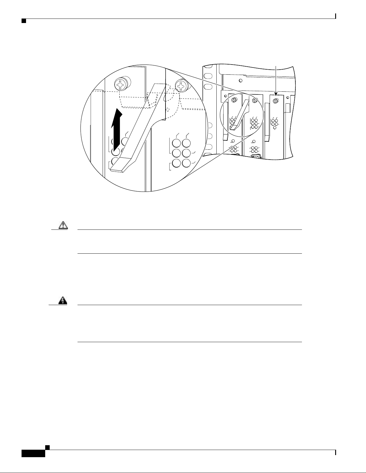
Figure 1-1 Using the Ejector Lever
Chapter1 Replacing or Installing Dial Shelf Cards
Panel fastener
Step 7
E1FR
HCPU
MONITOR#
LALM
75
Pull eithe r th e t op o r bottom ejector lever away f ro m t he card’s front panel to disengage the trunk card
E1FR
PWR
MAINT
T1FR
FCPU
HCPU
MONITOR#
RALM
NLOOP
LALM
75
0
HCPU
PWR
MAINT
PWR
MAINT
T1FR
FCPU
MODEMS
CALLS
RALM
NLOOP
H11097
from the b ack p lan e con n ect o r. (See Fig u re 1 -2.)
Caution Always use the ejector levers to disengage or seat dial shelf cards in the backplane. Failure
to do so can cause erroneous system error messages indicating a card failure. However, do
not use the eje cto r lever s to l if t or support t he w eight of th e car d s .
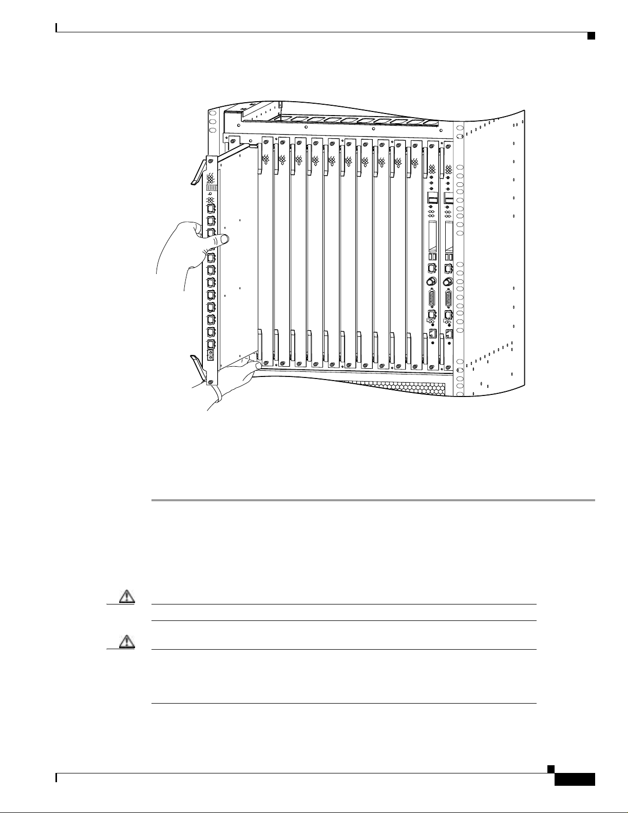
Step 8 Grasp the ejector levers and pull the card partially out of the dial shelf slot until you can grasp the card
front panel with one hand. Place your other hand under the card to balance the weight of the card a s you
pull it out of the slot. (See Figure 1-2.)
1-4
Step 9 For all cards, read the followi ng warni ng, then proce ed to Step 10 .
Warning
High performance devices on this card can get hot during operation, To remove the card,
hold it by the faceplate and bottom edge. Allow the card to cool before touching any
other part of it or placing it in an anti-static bag. To see translations of the w arnings that
appear in this publication, refer to the Regulatory Compliance and Safety Information
document that accompanied this device.
Step 10 Pull the card straight out of the slot. Avoid touching the circuitry or any connector pins.
Cisco AS5800 Universal Access Server Dial Shelf Card Guide
78-7097-03 0A
Page 21
Chapter1 Replacing or Installing Dial Shelf Cards
Figure 1 -2 Removing or Replacing a CT1/CE1 Trunk Card
Installing a Dial Shelf Card
Step 11
E1FR
HCPU
E1FR
MAINT
PWR
MONITOR#
T1FR
LALM
FCPU
75
HCPU
0
MONITOR #
1
RALM
NLOOP
LALM
75
0
1
2
3
4
5
6
7
8
9
10
11
RMON
TMON
CHANNELIZED E1/T1
2
3
4
5
6
7
8
9
10
11
RMON
TMON
CHANNELIZED E1/T1
HCPU
HCPU
PWR
MAINT
T1FR
FCPU
CALLS
RALM
NLOOP
MODEM
HCPU
HCPU
PWR
MAINT
PWR
MAINT
MODEMS
MODEMS
CALLS
CALLS
MODEM
MODEM
HCPU
HCPU
PWR
MAINT
PWR
MAINT
MODEMS
MODEMS
CALLS
CALLS
MODEM
MODEM
HCPU
HCPU
PWR
MAINT
PWR
MAINT
MODEMS
MODEMS
CALLS
CALLS
MODEM
MODEM
HCPU
PWR
MAINT
MODEMS
CALLS
MODEM
HCPU
PWR
MAINT
PWR
MAINT
PWR
MAINT
MBUS
PWR
MBUS
MODEMS
MODEMS
CALLS
CALLS
MODEM
MODEM
MODEMS
MAJ
ACO
CUTOFF
ALARM
CLEAR
ALARM
SET
DISP
ATTEN
DISP
CLK
MAST
SLOT 0
SLOT 1
PCMCIA
DIAL SHELF CONTROLLER
CONSOLE NETWORK CLOCK ALARMS 10 BASE T
DSI
DIAL SHELF INTERCONNECT
MIN
HIST
PWR
MAJ
MIN
ACO
HIST
CUTOFF
ALARM
CLEAR
ALARM
SET
DISP
ATTEN
DISP
CLK
MAST
SLOT 0
SLOT 1
PCMCIA
DIAL SHELF CONTROLLER
CONSOLE NETWORK CLOCK ALARMS 10 BASE T
DSI
DIAL SHELF INTERCONNECT
H11040
Place the removed card on an antistatic mat or foam pad until you are ready to reinstall it in the chassis.
If you pl an to r et ur n th e car d to t he fac to ry, place i t i n an an ti s tat ic ba g.
This co mplet es t he CT1/ CE1 tr unk ca rd r emo va l proce dur e. To install a CT 1/CE 1 tr unk ca rd , proc e ed to
the foll owi ng section, “Installing a Dial Shelf Card.”
Installing a Dial Shelf Car d
To install a new CT1/CE1 trunk card in the Cisco 5814 dial shelf, follow these steps:
Caution Trunk cards weigh 8 lb (3.6 kg) each. Use two hands when removing or replacing a card.
Caution To avoid erroneous failure messages, remove or insert only one dial shelf card at a time.
Also, after inserting or removing a dial shelf card, allow at least 15 seconds before
removi ng or in ser ti ng anot her di a l sh elf card so t ha t th e syste m c an re init i ali ze a nd note th e
current co nfigu r ati o n o f al l interfaces .
78-7097-03 0A
Cisco AS5800 Universal Access Server Dial Shelf Card Guide
1-5
Page 22

Installing a Dial Shelf Card
Step 1 Attach an ESD-preventive w ris t str ap b et w een y ou a nd an u n pa in ted c ha s sis s u rfac e.
Caution To prevent ESD d am age, handle ca r d s by ej e ctor lever s a n d carrie r edges on ly, and us e a n
ESD-preventive wrist strap or other grounding device.
Step 2 Carefully align the card carrier guides with the top and bottom grooves in the dial shelf slot. Avoid
touchi ng the circui tr y o r any co nn e c tor pi ns.
Step 3 Slide the card into the slot until the ejector levers make contact with the chassis frame. (See Figure 1-2.)
Step 4 Seat the card in the backplane by pushing the card firmly until the ejector levers fold in toward the card’s
front panel and the front panel is flush with the chassis frame.
Caution Always use the ejector levers to disengage or seat trunk cards, modem cards, VoIP cards,
or dial shelf controller cards in the backplane. Failure to do so can cause erroneous system
error messages indicating a card failure. However, do not use the ejector levers to lift or
support th e w eight of the c ar ds .
Chapter1 Replacing or Installing Dial Shelf Cards
Step 5 Tighten the pa ne l fa ste ne rs using a N o. 2 P hi ll ip s scr ewd r iver. This secur es the back p lan e co nn ec tio n
and ensures proper EMI shielding.
Caution Always tighten the panel fasteners. These fasteners prevent accidental removal and provide
proper grounding for the system.
Step 6 Repeat Step 2 through Step 5 for any other CT1/CE1 trunk cards that you want to install.
Step 7 Install a bl an k fi ll er card ( D S 58- BLANK= ) in al l e m pt y card slots to ke ep th e ch ass is du s t-f re e a nd
maintain proper airflow.
Caution To prevent the overhea ti ng of inte rn al co mp o nents, alway s i nst all blank filler c a rds in
empty slots to maintain the proper flow of cooling air across the cards.
This completes the CT1/CE1 trunk card replacement procedure.
1-6
Cisco AS5800 Universal Access Server Dial Shelf Card Guide
78-7097-03 0A
Page 23
Channelized T1 or E1 Trunk Card
The Cisco AS5800 universal ac ces s s er ver su pp o rts ch an nelized T1 (C T1 ) an d ch an ne lized E1 (CE1)
ingress interfaces that provide a synchronous telecommunications interface in both North American and
international environments. The CT1/CE1 trunk card is installed in the Cisco 5814 dial shelf in the
Cisco AS5800.
This chapter describes the , and it also includes steps for verifying and troubleshooting your CT1/CE1
trunk card installation.
CT1 and CE1 Trunk Card Overview
Channeli zed T1 or E1 i ngr es s i nt er fac es r es i d e o n CT1/CE1 t r un k car d s th at ar e in s tal le d in th e
Cisco 5814 dial she lf . A CT1/ CE1 tr unk card co nt ains all nece ssary func tio na lity to te rmi nate in comi ng
telephone calls. The channelized trunk card is configured in the factory for either T1 or E1 framing,
depending on your order.
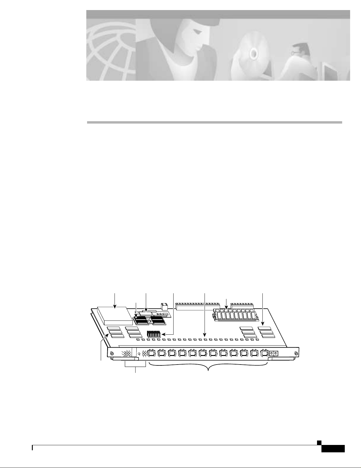
Figure 2-1 shows the CT1 and CE1 trunk card components.
CHAPTER
2
78-7097-03 0A
Figure 2-1 CT1 and CE1 Trunk Card
DC/DC converters
HDLC
controllers
MAINT
PWR
E1FR
CPU
FCPU
T1FR
LEDs
MBus
NLOOP
RALM
HCPU
75
0
1
MONITOR #
LALM
2
HDLC
FramersFramer CPU
controllers
DRAM SIMMs
3
4
5
6
7
8
9
10
TMON
RMON
11
12 ports
Cisco AS5800 Universal Access Server Dial Shelf Card Guide
CHANNELIZED E1/T1
H11283
2-1
Page 24

CT1 and CE1 Tru nk Card Overview
The CT1 and CE1 trunk cards perform the following functions:
• Termina te as many as 12 T1 o r 12 E1 lines
The CT1 tr u nk c ar d pr ovid es p hys i cal terminati on f o r as many as 12 T1 /P rimary Rat e I n ter fa ce
(PRI) lines, includes channel service units (CSUs), and connects directly to the telco network. The
CE1 trunk card pro v ides phys ic al te rmi na tion for as ma n y as 12 E1 l ines a nd conn ects to a n e xt er nal
networ k termin a ti on (NT 1 ) device.
• Demult ip lex cal ls
A framer r emo v es fra mi ng a nd embe d ded s igna li ng bi ts (or i nse rt s th em, depe ndin g o n t he di rect io n
of the f low ), and the f r am er CPU s ends t he d ata strea m t o o n bo a r d ti m e- d ivision multiplexin g
(TDM) resources, w hi ch b re ak ou t eac h cal l ( D S 0 ) an d p as s each call t o an ap pr o pri ate call
termination resource. Digital or ISDN-originated calls are terminated onboard the CT1/CE1 trunk
card on High-Level Data Link Control (HDLC) co ntrollers, and analo g mo dem-originated calls are
passed over the dial shelf backplane TDM bus to an available modem resource. The system software
contr ols mo de m and H D LC resource m anagement.
• Respond to time-sensitive signaling
Each T1 or E1 port can be used as the system clocking reference. Each CT1/CE1 trunk card can
supply two clocks from any two of its 12 ports. You can assign priorities to these clocks or accept
the default valu es ass igne d by the softw are.
Chapter2 Channelized T1 or E1 Trunk Card
• Process counting information for performance monitoring
• Support online insertion and removal (OIR)
The CT1/CE1 trunk card supports OIR, a featur e that allows you to rem ove and replace trunk cards
in the Cisco 5814 dial shelf while the system is operating, without disrupting other cards and their
associate d c a ll s. I f y o u remove a trun k c ar d wh il e th e s y stem is op er ati n g, a ll cal ls ass o ci at ed wi th
the lines on that card a re dropped. Calls being handled by other trunk or modem cards, however, are
not affected. For more information, see the “Busyout Command” section on page 1-1.
Figure 2-2 sho w s two CT1 /CE1 trunk cards in stalled in a fully-configur ed Cisco 5814 dial s helf chassis.
2-2
Cisco AS5800 Universal Access Server Dial Shelf Card Guide
78-7097-03 0A
Page 25
Chapter2 Channelized T1 or E1 Trunk Card
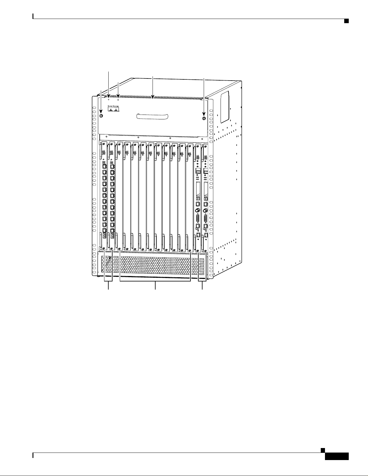
Figure 2-2 Cisco 5814 Dial Shelf Chassis Fully Configured with Cards Installed
POWER
LED
FAIL
Captive
screw
LED
P
O
W
E
R
F
A
I
L
Blower assembly
CT1 and CE1 Trunk Card Overview
Captive
screw
E1FR
PWR
MAINT
T1FR
FCPU
HCPU
MONITOR#
RALM
NLOOP
LALM
75
0
1
2
3
4
5
6
7
8
9
10
11
RMON
TMON
CHANNELIZED E1/T1
E1FR
PWR
MAINT
T1FR
FCPU
HCPU
MONITOR#
RALM
NLOOP
LALM
75
0
1
2
3
4
5
6
7
8
9
10
11
RMON
TMON
CHANNELIZED E1/T1
Cisco AS5800
HCPU
HCPU
HCPU
HCPU
PWR
MAINT
PWR
MAINT
MODEMS
MODEMS
CALLS
CALLS
MODEM
MODEM
HCPU
HCPU
PWR
MAINT
PWR
MAINT
MODEMS
MODEMS
CALLS
CALLS
MODEM
MODEM
HCPU
PWR
MAINT
MODEMS
CALLS
MODEM
HCPU
PWR
MAINT
PWR
MAINT
PWR
MODEMS
MODEMS
CALLS
CALLS
CALLS
MODEM
MODEM
MODEM
SERIES
HCPU
HCPU
MAINT
PWR
MAINT
PWR
MAINT
MBUS
PWR
MBUS
MODEMS
MODEMS
CALLS
MODEM
PWR
MODEMS
MAJ
MAJ
CALLS
MIN
MIN
ACO
ACO
HIST
HIST
CUTOFF
CUTOFF
ALARM
ALARM
CLEAR
CLEAR
ALARM
ALARM
SET
SET
DISP
DISP
ATTEN
ATTEN
DISP
DISP
CLK
CLK
MAST
MAST
SLOT 0
SLOT 0
SLOT 1
SLOT 1
PCMCIA
PCMCIA
DIAL SHELF CONTROLLER
DIAL SHELF CONTROLLER
CONSOLE NETWORK CLOCK ALARMS 10 BASE T
CONSOLE NETWORK CLOCK ALARMS 10 BASE T
DSI
DSI
DIAL SHELF INTERCONNECT
DIAL SHELF INTERCONNECT
MODEM
H10994
Clocking
78-7097-03 0A
Trunk cards
Modem cards Dial shelf
controller cards
All Cisco AS 5 8 00 acc ess ser ver trun k ca rds use the sa me tr an sm i t clo ck . Th is cl oc k can originate fro m
the foll owi ng so ur ces:
• TDM clock s ou r c e—A p ri or i ty valu e f r om 1 to 50 th at is a pp lied to a clock source when multipl e
clock sourc es are used
• External clock source—A clo ck source ex ter n al to th e access se rver
Clocks ar e pr i or itized by sl ot number (slo ts 0 to 5). The highest-prio rity clo ck is sele c ted from th e card
in slot 0 and use d as the de faul t c lo ck. If this cl oc k fa il s, the hi ghest -pr io rit y cl ock fro m th e card in s lot 1
becomes the default clock, and so forth.
Cisco AS5800 Universal Access Server Dial Shelf Card Guide
2-3
Page 26
CT1 and CE1 Tru nk Card Overview
The trunk car d th en for ward s th e cl oc ks t o t he dia l s h elf co n tr ol le r. The dial she lf co nt r ol ler s el ect s th e
highest-priority clock as the system primary clock, and the rest of the clocks remain in a prioritized
backup queue.
Instead of using the default algorithm for clock selection, you can specify clocks through global
configuration and select a maximum of two clocks per trunk card.
If you configure fewer than two clocks on a trunk card and all other configured clocks fail, clock
selection resorts to the default algorithm on that card and the second clock will be selected automatically.
LED and LC D I ndicators
The CT1 and CE1 trunk card front panels are designed with LED indicators (Figure 2-3) and a liquid
crystal display (LCD) (See Figure 2-4) to provide trunk card status and port-level monitoring
information.
Figure 2-3 CT1 and CE1 Trunk Card Front Panel LEDs
Chapter2 Channelized T1 or E1 Trunk Card
E1FR
MAINT
PWR
T1FR
FCPU
HCPU
Card-level LEDs
E1FR
MAINT
PWR
T1FR
FCPU
HCPU
MONITOR #
RALM
NLOOP
LALM
75
0
1
2
3
4
5
6
7
8
9
10
11
RMON
TMON
CHANNELIZED E1/T1
RALM
LALM
NLOOP
75
Port-associated LEDs
2-4
H10991
There are tw o ty pe s o f LED s f o r th e T 1 a nd E 1 tr un k car d s:
• Card-level LEDs, which provide status information for card maintenance
• Port-associated LEDs, which provide warning signals and configuration status for individual ports
Cisco AS5800 Universal Access Server Dial Shelf Card Guide
78-7097-03 0A
Page 27

Chapter2 Channelized T1 or E1 Trunk Card
All LEDs ar e v is i ble from the f ront panel. (See F i gu re 2-3.)
Table 2-1 lists the CT1 and CE1 trunk card LEDs and their functions.
Table 2-1 CT1 and CE1 Trunk Card LED Indicators
LED Color Description
PWR Green Power—Lights whe n 5V p ower is active.
MAINT Ye ll ow Maint en ance—Ligh ts when t he re ar e no active ca ll s o n t h e card
E1FR Green E1 framing—E1 trunk card only. Lights when the card is
T1FR Green T1 framing—T1 trunk card only. Lights when the card is
HCPU Green Host CPU—Lights when the host CPU is operating normally.
FCPU Green Framer CPU—Light s wh en th e f ram er CPU is o pe ra ti ng no r mally.
CT1 and CE1 Trunk Card Overview
and you have completed a card-level software busyout. Indicates
that the card is ready to be removed.
configured fo r E1 fr am in g.
configured fo r T1 fr am in g.
CT1 and CE1 Trunk Card Port Moni toring
The CT1 and CE1 trunk card front panels are designed with an LCD to provide trunk card status and
port-level monitoring information. (See Figure 2-4.) The current port number displayed in the LCD
correspond s t o th e f o ur p o rt -a ssoc ia ted LEDs.
Table 2-2 describes the port-associated LEDs and their functions.
Table 2-2 CT1 and CE1 Trunk Card Port-Associated LEDs
LED Color Description
LALM Y ellow Local alarm—Lights when an alarm condition is detected on
RALM Yellow Remote alarm—Ligh ts wh en t he asso ci at ed E1 p or t ha s
75 Green Ohm—E1 trunk card only. ON indicates 75 ohms, and OFF
NLOOP Yellow Network loopback—Lights when the port is configured in
1. LIU = line interface unit (analog physical interface). Refers to circuitry that interfaces a serial communications circuit to a
transmi s sion medium s uch as coaxial cabling.
incoming data.
detected loss of signa l (LOS) or out-of-frame (OOF) errors.
This occurs when the remote LI U
1
receiv es erro rs and sends
a signal to indicate th e presenc e o f r em o te er ror s .
indicates 1 2 0 ohms.
network loopback. This is useful for testing purposes.
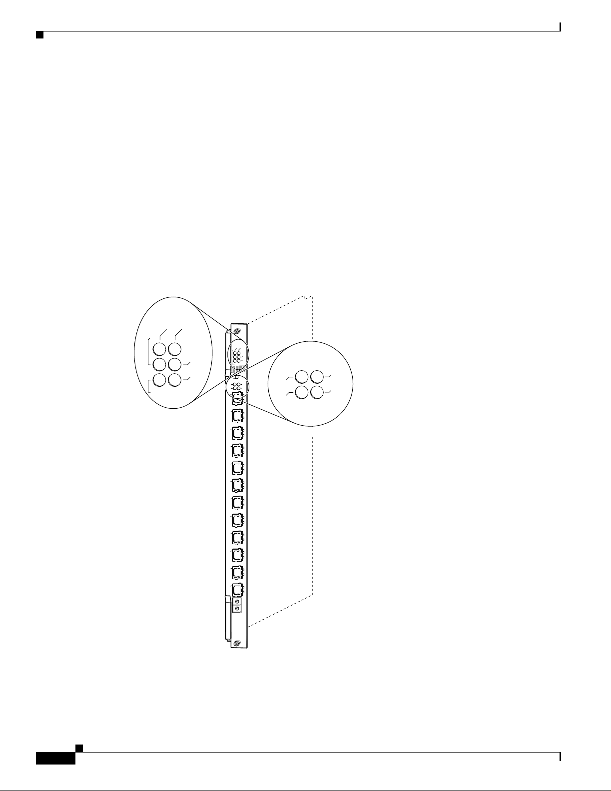
Trunk Card Bantam Jacks
Passi v e port moni torin g is sup por ted th rou gh t wo sha re d bant am j acks lo c ated at the bot to m of the tr unk
card front panel. (See Figure 2-4.) The bantam jac ks allow you to co nnect a network monitoring device
to the tr un k card to detect T 1 o r E1 errors.
The four-character LCD indicates which line is to be monitored or inspected using the bantam jacks.
78-7097-03 0A
Cisco AS5800 Universal Access Server Dial Shelf Card Guide
2-5
Page 28

CT1 and CE1 Tru nk Card Overview
To enable the bantam jacks for port monitoring, follow these steps:
Step 1 Push and quickly release the monitor button below the LCD to toggle to the port number you want to
monitor.
You must release the button within 2 seconds to advance through the port numbers (from 0 to 11). After
port 11, the display returns to port 0. As you advance through the port numbers, the LEDs reflect
configurati on s t at us and alarm co nd it io ns fo r th e po rt n u m b er dis p lay ed i n t h e LC D .
Step 2 Push and hol d th e mon it or b utto n f or 2 or more se conds to en able the ba nta m ja ck. To disable th e bant am
jack and return to toggle mode, press the button again and hold it for two or more seconds.
When you release the butto n, the port LCD no lon ger toggles through the port nu mbers, the letter “B” is
displayed in the LCD, and the bantam jacks are enabled.
Step 3 Repeat Step 1 and Ste p 2 to en ab le th e b an tam jacks f o r eac h p o rt that you wa n t to mo ni to r.
Figure 2-4 CT1 and CE1 Trunk Card Front Panel LCD and Bantam Jacks
Chapter2 Channelized T1 or E1 Trunk Card
GRP
1 TxD+
2 TxD–
3 RxD+
6 RxD–
H11006
2-6
Cisco AS5800 Universal Access Server Dial Shelf Card Guide
78-7097-03 0A
Page 29

Chapter2 Channelized T1 or E1 Trunk Card
Specifications
Table 2-3 lists the CT1 and CE1 trunk card specifications.
Table 2-3 CT1 and CE1 Trunk Card Specifications
Description Specification
Dimensions H x W x L 15.4 x 0.08 x 18.7 in. (39.12 x 0.203 x 47.5 cm) without the carrier
Weight 8 lb (3.6 kg)
Transmission bit rate
T1
E1
Power requirements 48 VDC (power consumption: 3.3 VDC and 5 VDC)
Regulatory compliance and safety
T1
CT1 and CE1 Trunk Card Overview
15.5 x 1.23 x 19 in. (39.37 x 3.12 x 48.26 cm) with the carrier
1.544 Mbps
2.048 Mbps
1
AT&T Accunet TR 62411 specifications; JATE2T98-6304-0;
Pan-Euro CE-0168-X
E1
ACA TS001, A53260; JATE N98-N019-0; Sweden 98031130;
Singapore ISDN2-IPTA-AE 0345-98;
Singapore DLCN1-MBPS-AO-0344-98; UK 607122
1. See al so the r e gulatory comp l ianc e and safet y do cum ent that shi pp ed wit h y our C is co AS5800.
2. JATE = Japan Approval Telecommunication Equipment.
CT1 and CE 1 Tru nk Card Port Pin out
The CT1 trunk ca rd re ceives and trans mit s 1. 544-Mb ps si gnal s th rou gh a 100- ohm ca ble, usi ng com mon
RJ-45 c o nn e c tors. U s e a straight -t hr ough RJ-45 to RJ-4 5 cabl e t o conn ect the T 1 li nes to an RJ- 4 5
receptacl e.
The CE1 tr unk card receives and transmits 2.048-Mbps CE1 si gnals through either 120-ohm or 75-ohm
coaxial ca bl e. A ll CE1 int er fa ce c ab les use co m mo n R J -45 co n nec to r s o n the dial sh el f e nd .
The re c e ive impedance is software configu r ab le as 7 5 ohms or 120 oh m s. The T1 defaul t va l ue is
100 ohm s . The E1 de fau lt value is 12 0 ohm s. Us e the li n e t erminat io n co m mand in co ntro ll er
configurati o n m od e to co nfi gur e t he r ece ive imp ed a n ce.
78-7097-03 0A
Cisco AS5800 Universal Access Server Dial Shelf Card Guide
2-7
Page 30

CT1 and CE1 Tru nk Card Overview
Chapter2 Channelized T1 or E1 Trunk Card
Table 2-4 lists the CT1 and CE1 port pinouts.
Table 2-4 CT1 and CE1 Trunk Card Port (RJ-45) Pinouts
Pin Signal
1 Receive tip
2 Receive ring
3 Jumpe re d gro un d
4 Transmit tip
5 Transmi t ri ng
6 Jumpe re d gro un d
7Not used
8Not used
Warning
To avoid electric shock, do not connect safety extra-low voltage (SELV) circuits to
telephone network voltage (TNV) circuits. LAN ports contain SELV circuits and WAN
ports contain TNV circuits. Some LAN and WAN ports both use RJ-45 connectors. To see
translations of the warnings that appear in this publication, ref er to t he Regulat ory
Compliance and Safety Information that accompanied this device.
CT1 Trunk C ard Cables and Pinouts
One inte rface cable i s available from Ci sco S y stems for co n ne cti n g t he C T 1 car d p ort s . Th e cab le is
described in Ta ble 2-5.
Tab le 2-5 CT1 In te rfac e Ca b le
Cable Description Product Number
RJ-45 to bare wire, 100-ohm CAB-T1-RJ45BARE
Figure 2-5 shows the CT1 interface cable, and Table 2-6 describes the pinouts for the CT1 interface
cable.
Figure 2-5 RJ-45 to Bare Wir e Interface Cable
J1
H10984
2-8
Cisco AS5800 Universal Access Server Dial Shelf Card Guide
78-7097-03 0A
Page 31

Chapter2 Channelized T1 or E1 Trunk Card
Table 2-6 RJ-45 to Bare Wire Interf ace Cable Pinouts
RJ-45 Pin Signal Description Direction B are
Shield Ground Braid ——
J1-1 RX Tip Twisted Pair #1 <— WIRE-1
J1-2 RX Ring Twisted Pair #1 <— WIRE-2
J1-3 RX Shield ———
J1-4 TX Tip Twisted Pair #2 —>WIRE-3
J1-5 TX Ring Twisted Pair #2 —>WIRE-4
J1-6 TX Shield ———
CE1 Trunk C ard Cables and Pinouts
Seven interface cables are available from Cisco Systems for connecting the CE1 card ports. These cables
and thei r pr odu ct nu mbe rs a re li ste d i n Table 2-7, along with t he numbe r of t he f igure a nd ta bl e det ail in g
their pi no uts.
CT1 and CE1 Trunk Card Overview
Table 2-7 CE1 Interface Cables
Cable Description Product Number Illustration Pinout
RJ-45 to RJ-45, 120-ohm CAB-E1-RJ45RJ45 Figure 2-6 Table 2-8
RJ-45 to DB-15, 120-ohm CAB-E1-RJ45DB15 Figure 2-7 Table 2-9
RJ-45 to DB-15 null,
CAB-E1-RJ45DB15N Figure 2-7 Table 2-10
120-ohm
RJ-45 to BNC, 75-ohm CAB-E1-RJ45BNC Figure 2-8 Table 2-11
RJ-45 to Twinax, 75-ohm CAB-E1-RJ45TWIN Figure 2-9 Table 2-12
RJ-45 to R J-45 TE , 12 0-o hm CAB-E 1-R J45TE Figure 2-10 T a ble 2-13
RJ-45 to RJ-45 NT,
CAB-E1-RJ45NT Figure 2-10 Table 2-14
120-ohm
Figure 2-6 RJ-45 to RJ-45 Interface Cable
J1
J2
H10983
78-7097-03 0A
Cisco AS5800 Universal Access Server Dial Shelf Card Guide
2-9
Page 32

CT1 and CE1 Tru nk Card Overview
Table 2-8 RJ-45 to RJ-45 E1 Cable Pinout s (Crossover)
RJ-45 Pin Signal Description Direction R J-45 T1 Pin
Shield Gr ou n d Shell/Br aid — Shield
J1-1 RX Tip Twisted Pair #1 <— J2-4
J1-2 RX Ring Twisted Pair #1 <— J2- 5
J1-3 — RX Shield ——
J1-4 TX Tip Twisted Pair #2 —>J2-1
J1-5 TX Ring Twisted Pair #2 —>J2-2
J1-6 — TX Shield ——
Figure 2-7 RJ-45-to-DB-15 Interface Cable
J1
Chapter2 Channelized T1 or E1 Trunk Card
J2
H10982
Table 2-9 RJ-45 to DB-15 Cable Pinouts
RJ-45 Pin Signal Description Direction DB -15 Pin
Shield Gr ou n d Shell/Br aid — Shell
J1-1 RX Tip Twisted Pair #1 <— J2-3
J1-2 RX Ring Twisted Pair #1 <— J2- 11
J1-3 RX Shield Twisted Pair #3 — J2-4
J1-4 TX Tip Twisted Pair #2 —>J2-1
J1-5 TX Ring Twisted Pair #2 —>J2-9
J1-6 TX Shield Twisted Pair #4 — J2-2
Table 2-10 RJ-45 to DB-15 Null-Modem Cable Pi nouts
RJ-45 Pin Signal Description Direction DB -15 Pin
Shield Gr ou n d Shell/Br aid — Shell
J1-1 RX Tip Twisted Pair #1 <— J2-1
J1-2 RX Ring Twisted Pair #1 <— J2- 9
J1-3 RX Shield Twisted Pair #3 — J2-2
J1-4 TX Tip Twisted Pair #2 —>J2-3
J1-5 TX Ring Twisted Pair #2 —>J2-11
J1-6 TX Shield Twisted Pair #4 — J2-4
2-10
Cisco AS5800 Universal Access Server Dial Shelf Card Guide
78-7097-03 0A
Page 33

Chapter2 Channelized T1 or E1 Trunk Card
Figure 2-8 RJ-45 to BNC Interf ace Cable for 75-Ohm (Unbalanced Connections)
J1
Table 2-11 RJ-45 to BNC Cable Pinouts
RJ-45 Pin Signal Description Direction BNC Pin
Shield Ground Sh ell — RX, TX
J1-1 RX Tip Twisted Pair #1 <— RX-Tip
J1-2 RX Ring Twisted Pair #1 <— RX-Shield
J1-3 RX Shield Twisted Pair #3 — RX-Shield
J1-4 TX Tip Twisted Pair #2 —>TX-Tip
J1-5 TX Ring Twisted Pair #2 —>TX-Shield
J1-6 TX Shield Twisted Pair #4 — TX- Sh ield
CT1 and CE1 Trunk Card Overview
RX
TX
H10660
Shields
Figure 2-9 RJ-45 to Twinax Interface Cable for 75-Ohm (Unbalanced Connections)
J1
Table 2-12 RJ-45 to Twinax Cable Pinou ts
RX
H10659
TX
RJ-45 Pin Signal Description Direction Twinax Pin
Shield Ground Sh ell — RX, TX
Shields
J1-1 RX Tip Twisted Pair #1 <— RX-1
J1-2 RX Ring Twisted Pair #1 <— RX-2
J1-3 RX Shield Twisted Pair #3 — RX Shield
J1-4 TX Tip Twisted Pair #2 —>TX-1
J1-5 TX Ring Twisted Pair #2 —>TX-2
J1-6 TX Shield Twisted Pair #4 — TX Shi eld
Figure 2-10 RJ-45 to RJ-45 Inte rface Cable
78-7097-03 0A
J1
J2
H10983
Cisco AS5800 Universal Access Server Dial Shelf Card Guide
2-11
Page 34

CT1 and CE1 Tru nk Card Overview
Table 2-13 RJ-45 to RJ-45 TE Cable Pi nouts (Straight-thr ough)
RJ-45 Pin Signal Description Direction R J-45 TE Pin
Shield Gr ou n d Shell/Br aid — Shield
J1-1 RX Tip Twisted Pair #1 <— J2-1
J1-2 RX Ring Twisted Pair #1 <— J2- 2
J1-3 RX Shield Twisted Pair #3 — J2-3
J1-4 TX Tip Twisted Pair #2 —>J2-4
J1-5 TX Ring Twisted Pair #2 —>J2-5
J1-6 TX Shield Twisted Pair #4 — J2-6
Table 2-14 RJ-45 to RJ-45 NT Cable Pinouts (Crossover)
RJ-45 Pin Signal Description Direction Signal RJ-45 NT Pin
Shield Gr ou n d Shell/Br a id — Ground Shield
J1-1 RX Tip Twisted Pair #1 <— TX Tip J2-4
J1-2 RX Ring T wi ste d P air #1 <— TX Ring J2-5
J1-3 RX Shield T wi ste d P air #3 — TX Shield J2-6
J1-4 TX Tip Twisted Pair #2 —>RX Tip J2-1
J1-5 TX Ring Twis ted Pair #2 —>RX RingJ2-2
J1-6 TX Shield Twis ted P a ir #4 — RX Shield J2-3
Chapter2 Channelized T1 or E1 Trunk Card
Warning
To avoid electric shock, do not connect safety extra-low voltage (SELV) circuits to
telephone network voltage (TNV) circuits. LAN ports contain SELV circuits and WAN
ports contain TNV circuits. Some LAN and WAN ports both use RJ-45 connectors. To see
translations of the warnings that appear in this publication, ref er to t he Regulat ory
Compliance and Safety Information that accompanied this device.
Connecti ng Trunk Card Cables
The CT1 a nd C E1 t run k ca rds p ro vi de 1 2 RJ- 45 re cept acl es for T1 or E1 l in es. To connect T 1or E1 l ines ,
follow these steps:
Step 1 Attach th e RJ - 4 5 en d of th e T1 or E 1 cab le d ir ect ly to t he RJ-45 r ece pt acl e o n th e t r un k card . (S ee
Figure 2-11.)
Step 2 For T1 cabling, attach the network end of your CT1 cables to your external network.
Step 3 For E1 cabling, attach the network e nd of your CE1 cables to your network termination (NT1) device.
2-12
Cisco AS5800 Universal Access Server Dial Shelf Card Guide
78-7097-03 0A
Page 35

Chapter2 Channelized T1 or E1 Trunk Card
CT1 and CE1 Trunk Card Overview
Warning
Hazardous network voltages are present in WAN ports regardless of whether power to
the unit is OFF or ON. To avoid electric shock, use caution when working near WAN
ports. When detaching cables, detach the end away from the unit fi rst. To see
translations of the warnings that appear in this publication, ref er to t he Regulat ory
Compliance and Safety Information that accompanied this device.
Figure 2-11 CT1 and CE1 Trunk Card RJ-45 Cable Connections
H11005
6
7
8
9
1
0
1
1
1
2
1
3
1
4
1
5
1
6
1
7
1
8
1
9
2
0
Warning
To avoid electric shock, do not connect safety extra-low voltage (SELV) circuits to
telephone network voltage (TNV) circuits. LAN ports contain SELV circuits and WAN
ports contain TNV circuits. Some LAN and WAN ports both use RJ-45 connectors. To see
translations of the warnings that appear in this publication, ref er to t he Regulat ory
Compliance and Safety Information that accompanied this device.
Configuring Ca bl e Length
When you configure your CT1 trunk cards, you must include the length of the cable connected to the
card. To specify th is l en gt h, us e th e ca b lel eng th command . No cablelength command is r eq ui r ed for
CE1 trun k ca rds.
If you change the cable length when installing and cabling a new trunk card, you need to specify cable
length in your software configuration. The cablelength command is designed to reco gnize two settings:
• Cable Length Short
• Cable Lengt h L o ng
78-7097-03 0A
Cisco AS5800 Universal Access Server Dial Shelf Card Guide
2-13
Page 36

CT1 and CE1 Tru nk Card Overview
Cabl e L ength Short
Note Although t he cabl e le ngth c an ra nge from 0 to 655 f ee t, t he ha rdw are re cog nize s onl y f i xed
Cabl e L ength Long
Chapter2 Channelized T1 or E1 Trunk Card
Cable length short defines the length of the cable (in feet) between your network access server (NAS)
and you r re pea ter. The cab le leng th short comma nd include s th e fo ll owi ng settings :
• 133 feet (0 to 133 feet)
• 266 feet (134 to 266 feet)
• 399 feet (267 to 399 feet)
• 533 feet (400 to 533 feet)
• 655 feet (534 to 655 feet)
lengths. F or ex am p le , i f th e cable len gt h be tw ee n yo u r NAS and y ou r r ep eat er is 50 feet,
you should configure your cable length using the 133 feet setting. If you later change the
cable le ng t h t o 200 f eet , r econfigur e yo u r cab le leng th u s in g th e 26 6 feet s et ting.
Cable length long defines the length range between your NAS and your repeater in gain and pulse. The
cableleng th long command includes the fo ll owi ng g ain an d p ul s e settings :
• gain 2 6 ( 2 6 db ga in )
• gain 3 6 ( 3 6 db ga in )
• -15 db (-15 db pulse)
• -22.5 db (-22.5 db pulse)
• -7.5 db (-7.5 db pulse)
• 0 db ( 0 db pulse)
T o con f igure cab le leng th , you m ust be in gl oba l con f ig urat io n mode . Table 2-15 lists commands to help
you configure your CT1 lines using the cablelength command .
Note When you configure your system for CT1 lines, you must also include additional
commands to define framing, line code, clock source, signaling, and so forth. For complete
instruc tio ns on how to configure your t run k ca rd l ine s, refe r to t he Cis co AS5800 Univers al
Access Server Operation, Administration, Maintenance, and Provisioning Guide that
shipped with your system.
2-14
Cisco AS5800 Universal Access Server Dial Shelf Card Guide
78-7097-03 0A
Page 37

Chapter2 Channelized T1 or E1 Trunk Card
Table 2-15 Configuring Channelized T1 Cable Length
Command Description
Step 1
Step 2
Step 3
Step 4
AS5800> enable
Password: password
AS5800#
AS5800# configure terminal
Enter configuration commands, one per
line. End with CNTL/Z.
AS5800(config)#
AS5800(config)# controller t1
shelf/slot/port
AS5800(config-controller)#
cablelength short 133
[or]
CT1 and CE1 Trunk Card Overview
Enter the enable command .
Enter your password.
You are in privileged EXEC mode when the prompt
changes to
Enter global configuration mode by typing the
configure terminal command. The example uses the
terminal configuration option.
You are in global configuration mode when the
prompt changes to
Enter controller configuration mode by typing
controller t1 to configure your controller port. The
controller p or ts ar e l ab eled shelf/slot/0 through
shelf/slot/11 on th e T3 card s.
Enter the controller cablelength short value (133,
266, 399, 533, or 655).
AS5800#.
AS5800(config)#.
AS5800(config-controller)#
cablelength long gain 26
Enter the controller cablelength long value us ing
gain 26 or gain 36 and pulse (-15, -22.5, -7.5, or 0).
This completes the trunk card installation procedure. To verify the installation, proceed to the following
section, “Verifying and Troubleshooting the Installation.”
Verifyin g and Troubleshoot ing the Insta l l at ion
When you first power ON your Cisco AS5800 access server, all LEDs light while the system runs a series
of diagn o s ti cs . A f te r th e s y stem pass e s in it ial dia gnostics, all LED s g o o ff. T he L ED s th en light ag ain
as des c ribed in Table 2-1.
T o compl ete th e insta llati on, verify t hat the trunk card LEDs opera te prope rly b y observ ing th e follo wing
LED states:
• The power LED i s O N .
If the powe r LED r em ains O F F, verify t hat the card is se ated prop er l y.
If the powe r LED lights on other trunk cards in the dial shelf, try inserting the trunk card in a
different slot. If none of the power LEDs lights, check your dial shelf power connections, power
entry m o dules, a nd AC-in pu t power su pplies (if pre sent).
78-7097-03 0A
Cisco AS5800 Universal Access Server Dial Shelf Card Guide
2-15
Page 38

Configuring the CT1 and CE1 Trunk Card
• The HCPU LED is ON.
If the HCPU LED is OFF but the power LED is ON, the software image might have failed to load
onto the ca rd . The d ial s h elf c on tr o ll er at tempts to r el oa d th e s o f tw are au to matically. After a
programmed number of attempts to reload the software image fails, the dial shelf controller powers
OFF the trunk card and all LEDs shut off.
If this h ap pens, assume th at th e f ai lu re is du e t o de fective hard wa re . Return th e card to th e factory
for replac ement. For i nfo rm ati on o n how t o co nt act C isco , see the “Obta inin g Doc ume ntat ion”
section on page xiv.
• The FCPU LED is ON.
If the FCPU LED is OFF while the HCPU LED is ON, either the hardware is defective or the framer
proce ssor s o ftware has cras he d. To det er m ine if the fa i l u r e i s s oftwa re related , w a it wh ile the
auto-re loa d feature on th e dial she lf co n tr o lle r car d at tempts to reload th e so f twa re image. If t he
software fai ls to relo ad afte r the prog ram me d numb er of tim es, assu me th at the fail ure is du e to
defective hard wa re . R etu r n th e card to th e fact o ry f o r r ep l ace m en t.
Tips For further installation troubleshooting information, refer to the Cisco AS5800 Universal
Access Server Hardware Installation Guide.
Chapter2 Channelized T1 or E1 Trunk Card
Configuring the CT1 and CE1 Trunk Card
The Cisco 5814 dial shelf recognizes CT1 and CE1 trunk cards only in slots 0 to 5 within the dial shelf
chassis. Therefore, install trunk cards only i n one of t he first six slots.
If you are replacing a dial shelf card by installing a new dial shelf card of the same type in the same slot,
the system so ft wa re rec og n ize s the new dial shelf card in ter fa ces an d bri n gs th em u p au to m a tic ally. No
addition al co n figur at io n is n ee de d.
If you are ins talling a trunk card in a dif ferent slo t than the trunk ca rd that you just removed, additional
configuration is needed. Refer to the Cisco AS5800 Universal Access Server Operation, Administration,
Maintenance, and Provisioning Guide to configure the CT1 and CE1 interfaces.
2-16
Cisco AS5800 Universal Access Server Dial Shelf Card Guide
78-7097-03 0A
Page 39

Channelized T3 Trunk Card
The Cisco AS5800 universal ac ces s s erver su pp o rts a channe liz ed T3 ( CT 3) ingress i nter fac e t ha t
provides a syn ch r on o us ag gr ega tio n o f cha nnelized in terfaces an d mu ltiplexing o n a s i ngle T3 faci lit y.
The CT1/CE1 trunk card is installed in the Cisco 5814 dial shelf chassis in slots 0 to slot 5. The
Cisco AS5800 currently supports as many as two CT1/CE1 trunk cards.
This chapter explains how to remove and replace a CT1/CE1 trunk card in the Cisco 5814 dial shelf
chassis, and also includes steps for verifying and troubleshooting your trunk card installation and
configu rin g you r sof twar e.
CT1/CE1 Trunk Card Overview
The CT1/ CE1 trunk card contains an onboard M13 mul tiplexer, which multipl exes 28 separate T1 lines
into a single T3 line. Each CT1/CE1 trunk card installed in the Cisco 5814 dial shelf contains all
necessa ry f u nc tionality to terminate lin k sig naling and inc oming di gi tal calls.
Figure 3-1 shows the CT1/CE1 trunk card.
CHAPTER
3
78-7097-03 0A
Cisco AS5800 Universal Access Server Dial Shelf Card Guide
3-1
Page 40

CT1/CE1 Trunk Card Overview
Figure 3-1 CT1/CE1 Trunk Card
MONITOR #
Chapter3 Channelized T3 Trunk Card
PWR
MAINT
MAINT
PWR
FCPU
HCPU
RALM
NLOOP
LALM
FCPU
HCPU
Receive BNC connector
Transmit BNC connector
Transmit DSx1 connector
Receive DSx1 connector
T3LOOP
AIS
T3EN
OOF
LOS
FERF
RCVR
XMTR
TX (OUT)
RX (IN)
CHANNELIZED T3
MONITOR #
LALM
T3EN
LOS
FERF
RALM
NLOOP
T3LOOP
AIS
OOF
12125
Each CT1/CE1 trunk card performs the following functions:
• Provides physical termination for as many as 672 sessions.
3-2
• Provides digital terminatio n for as many as 256 DS0 connections (calls) using onboard High-L evel
Data L in k Co nt ro l ( HDL C) co nt ro ll er s. Not e tha t th e D- ch an ne l of a P R I co ns ume s a si ngl e ch an ne l
of an HDL C co ntro ll er.
• Removes framing and embedded signaling bits (or inserts them, depending on the direction of the
flow), demulti pl exi ng th e calls. Th e f r am er C P U s e nd s t he data str eam to on bo a rd time- d ivisio n
multiplexi ng ( TD M ) r eso ur ce s, w h ich b r eak o u t each call an d pa s s each call to an ap p rop ri at e call
termination resource. Digital or ISDN-originated calls are terminated onboard the CT1/CE1 trunk
card on HDLC cont roll ers.
Note Each D-channel consumes an HDLC controller.
Analog mo dem-origin at ed calls are p as sed over the d i al shelf b ack pl an e T D M bus t o an availa bl e
modem resource. The system software co ntrols mode m and H DLC resource man agem ent.
• Respond s to time -sensit iv e signa ling. E ach CT1/C E1 trunk c ard can sup ply tw o clocks from an y two
of its 28 ports. You can assign priorities to these clocks or ac cept the default values assigned by the
software.
Cisco AS5800 Universal Access Server Dial Shelf Card Guide
78-7097-03 0A
Page 41

Chapter3 Channelized T3 Trunk Card
• Processes counting information for performance monitoring.
• Support s online ins erti on and remo va l (OIR), a fe ature t hat allo ws you to re mov e and replac e a trunk
card in the Cisco 5814 dial shelf while the system is operating without disrupting other cards and
their asso ci at ed call s . I f you r em ove a trun k c ar d w h ile th e s yst em i s op er at in g, a ll c all s ass o cia ted
with the CT3 lines on that card are dropped. Calls being handled by other trunk or modem cards,
however, are not affected. For more information, see the “Online Insertion and Removal” section on
page 1 -1.
Figure 3-2 shows two trunk cards installed in a fully-configured Cisco 5814 dial shelf chassis.
Figure 3-2 Cisco 5814 Dial Shelf Chassis Fully Configured with Trunk Cards Installed
POWER
LED
Captive
screw
P
O
W
E
R
FAULT
LED
F
A
I
L
Blower assembly
CT1/CE1 Trunk Card Overview
Captive
screw
MAINT
PWR
FCPU
HCPU
MONITOR #
RALM
NLOOP
LALM
T3LOOP
AIS
T3EN
OOF
LOS
FERF
RCVR
XMTR
TX (OUT)
RX (IN)
CHANNELIZED E1/T1
MAINT
PWR
FCPU
HCPU
MONITOR #
RALM
NLOOP
LALM
T3LOOP
AIS
T3EN
OOF
LOS
FERF
RCVR
XMTR
TX (OUT)
RX (IN)
CHANNELIZED E1/T1
Cisco AS5800
HCPU
HCPU
HCPU
HCPU
PWR
MAINT
PWR
MAINT
MODEMS
MODEMS
CALLS
CALLS
MODEM
MODEM
HCPU
HCPU
PWR
MAINT
PWR
MAINT
MODEMS
MODEMS
CALLS
CALLS
MODEM
MODEM
HCPU
PWR
MAINT
MODEMS
CALLS
MODEM
HCPU
PWR
MAINT
PWR
MAINT
PWR
MODEMS
MODEMS
CALLS
CALLS
CALLS
MODEM
MODEM
MODEM
SERIES
HCPU
HCPU
MAINT
PWR
MAINT
PWR
MAINT
MBUS
PWR
MBUS
MODEMS
MODEMS
CALLS
MODEM
PWR
MODEMS
MAJ
MAJ
CALLS
MIN
MIN
ACO
ACO
HIST
HIST
CUTOFF
CUTOFF
ALARM
ALARM
CLEAR
CLEAR
ALARM
ALARM
SET
SET
DISP
DISP
ATTEN
ATTEN
DISP
DISP
CLK
CLK
MAST
MAST
SLOT 0
SLOT 0
SLOT 1
SLOT 1
PCMCIA
PCMCIA
DIAL SHELF CONTROLLER
DIAL SHELF CONTROLLER
CONSOLE NETWORK CLOCK ALARMS 10 BASE T
CONSOLE NETWORK CLOCK ALARMS 10 BASE T
DSI
DSI
DIAL SHELF INTERCONNECT
DIAL SHELF INTERCONNECT
MODEM
12266
78-7097-03 0A
Trunk cards
Modem cards Dial shelf
controller cards
Cisco AS5800 Universal Access Server Dial Shelf Card Guide
3-3
Page 42

CT1/CE1 Trunk Card Overview
Clocking
Chapter3 Channelized T3 Trunk Card
All Cisco AS 5 8 00 acc ess ser ver trun k ca rds use the sa me tr an sm i t clo ck . Th is cl oc k can originate fro m
the foll owi ng so ur ces:
• TDM clock s ou r c e—A p ri or i ty valu e f r om 1 to 5 0 th at is app li ed to a clock sou r ce wh en multip l e
clock sourc es are used
• External clock source—A clo ck source ex ter n al to th e access se rver
Clocks ar e pr i or itized by sl ot number (slo ts 0 to 5). The highest-prio rity clo ck is sele c ted from th e card
in slot 0 and used as th e defa ul t c lock . If thi s c l ock f a ils , t he highe st -pr io rity cl ock fro m th e ca rd i n sl ot 1
becomes the default clock, and so forth.
The trunk car d th en for ward s th e cl oc ks t o t he dia l s h elf co n tr ol le r. The dial she lf co nt r ol ler s el ect s th e
highest-priority clock as the system primary clock, and the rest of the clocks remain in a prioritized
backup queue.
Instead of using the default algorithm for clock selection, you can specify clocks through global
configuration and select a maximum of two clocks per trunk card.
If you configure fewer than two clocks on a trunk card and all other configured clocks fail, clock
selection resorts to the default algorithm on that card and the second clock will be selected automatically.
CT3 Clocking
CT1/CE 1 tr unk car d s are usually at tached to an ex ter n al devi ce, su ch as a D ig it al A cce s s an d
Crossconnect System (DACS) or Add-Drop Multiplexer (ADM). This point-to-point link requires a
single clock source to whic h the CT3 link is time d. You must determine whether you want the CT1/CE1
trunk ca rd o r an ex ter n al devi ce t o be u sed as th e p r imar y cl ock sour ce an d con figu re it according ly
during the so ft ware c onf igu ra tion pr oces s, wh ic h is di scus se d in t he “Conf igur at io n Com man ds” section
on page 3-12.
CT1 Clocking
The CT1/CE1 trunk card has 28 T1 framers that always get their clock from the line. As a result,
configuration of T1 clock sources is not allowed.
LED and A l phan um eri c I ndicators
The CT1/CE1 trunk card front panel is designed with LED and alphanumeric displays to provide trunk
card status. (See Figure 3 -3.)
3-4
Cisco AS5800 Universal Access Server Dial Shelf Card Guide
78-7097-03 0A
Page 43

Chapter3 Channelized T3 Trunk Card
Figure 3-3 CT1/CE1 Trunk Card Front Panel LED and Alphanumeric Indicators
MAINT
PWR
HCPU
MONITOR #
LALM
CT1/CE1 Trunk Card Overview
MAINT
PWR
FCPU
RALM
NLOOP
FCPU
HCPU
Alphanumeric display
T3LOOP
AIS
T3EN
OOF
LOS
FERF
RCVR
XMTR
TX (OUT)
RX (IN)
CHANNELIZED T3
MONITOR #
LALM
T3EN
LOS
FERF
RALM
NLOOP
T3LOOP
AIS
OOF
12240
Table 3-1 lists the CT1/CE1 trunk card LEDs and their functions.
78-7097-03 0A
Table 3-1 CT1/CE1 Trunk Card LED Indi cators
LED Color Des criptio n
PWR Green Power—Lights when power is ON.
MAINT Yellow Maintenance—Lights to indicate that the feature card is ready for OIR.
HCPU Green Host CPU—Lights wh en t he ass o ci ate d host CP U i s d etermined to b e in
good wo rking co ndit io n; shut s off when there is an e rror c ondit io n or code
is being downloaded.
FCPU Green Framing data link—Lights when the associated FDL CPU is determined to
be in goo d w or kin g con di ti on; s hut s of f whe n ther e is a n er ror condi t io n or
code is be i n g downloaded.
LALM Yellow Local alarm—Lights to indicate a T1 alarm condition was encountered by
software for a particular port; remains OFF when the operating condition
is norm al.
Cisco AS5800 Universal Access Server Dial Shelf Card Guide
3-5
Page 44

CT1/CE1 Trunk Card Overview
Table 3-1 CT1/CE1 Trunk Card LED Indicators (continued)
LED Color Des criptio n
RALM Yellow Remote alarm—Li ghts to ind icate a T1 alar m co ndit ion wa s encoun te red
NLOOP Yellow Network loop—Lights to indicate that at least one T1 is unavailable (status
T3EN Green
T3LOOP
LOS Yellow
AIS Yellow
FERF Yellow
OOF Yellow
1. This LED must be lit for proper CT3 operation.
2. When in loopback mode, enables diagnostics to perform local CT3 testing without external support. The CT3 line is not
3. This LED must remain off for proper CT3 operation.
by software for a particular port; remains OFF when the operating
conditio n is no rma l.
indicator); remains OFF when the operating condition is normal.
1
Enable—Lights to indicate a CT3 card line connection enabling normal
operatio n.
2
affecte d by th is c ond i ti on, t hu s re ma i ning disconn ect ed a nd open.
Yellow3Loopback—Lights to indi ca te th at a loo pba ck co ndi tion e xi sts on the CT3
line; s oftwa re controlled.
3
Loss-of-signal—Lights to i ndicate that t he CT3 fram er is ex periencing a
loss of signal (175 successive zeros).
3
Alarm in di cat io n sig na l—Ligh ts t o in di cat e t he p re s en ce of AI S in t he
received CT 3 li ne. Ligh ts to ind icate th at a T3 alarm condition exi s ts;
remains OFF when the operating condition is normal.
3
Far-end receive failure—Lights to in dica te a f ar - end rec ei v e fail ur e on the
CT3 lin e .
3
Out-of-frame—Lights to indicate an out-of-frame condition on the CT3
line.
Chapter3 Channelized T3 Trunk Card
Trunk Card Connectors
The CT3 front panel is designed with two types of cable connectors (see Figure 3-4). The BNC
connecto rs ar e u sed t o co nn ec t t he cab les carry in g th e T 3 sig na ls. The ban tam jacks ar e used fo r lo cal
BERT circuit testin g to the DS1 leve l.
3-6
Cisco AS5800 Universal Access Server Dial Shelf Card Guide
78-7097-03 0A
Page 45

Chapter3 Channelized T3 Trunk Card
Figure 3-4 CT1/CE1 Trunk Card Front Panel Connectors
Using the Test Port
Receive BNC connector
RCVR
Transmit BNC connector
XMTR
Cables
Transmit DSx1 bantam
jack connector
Receive DSx1 bantam
jack connector
TX (OUT)
RX (IN)
CHANNELIZED T3
12241
The CT1/CE 1 trun k card rec eiv es an d trans mits 45 Mbps signal s throug h a 75-o hm cable, using c ommon
BNC coax i al c a b le co nnectors (se e F i gu r e 3- 5). There are two fem ale BNC c on n ect or s: on e fo r T3
transmit data and one for T3 receive data.
Figure 3-5 CT3 75-Ohm Coaxial Cable
Using t he Test Port
The CT3 trunk card front panel is designed with an alphanumeric display to provide trunk card status
and port monitoring information (see Figure 3-3).
Test-port functionality is supported by Cisco IOS Release 12.0(6)T and later releases.
78-7097-03 0A
12951
Cisco AS5800 Universal Access Server Dial Shelf Card Guide
3-7
Page 46

Using the Te st Port
Trunk Card Bantam Jacks
The test port is a set of bantam jack connectors located at the bottom of the CT3 front panel (see
Figure 3-4 ). Th e b an tam jacks a llow t he co nnection o f an ext er na l t est devi ce (fo r exam pl e, a
FIREBERD te st de v ice) t o tes t a n y of th e 28 individual T1 cir cu its i n dro p-a nd -ins ert mod e or to m onit or
an individual T1 circuit in monitor mode.
• In drop-a nd-i nse rt mod e, the T1 l in e is drop ped ou t of serv ice . To preven t acc ide nt al us e of t he pus h
button in drop-and-insert mode, use the test trunk dro p-insert privileged EXEC co mma nd t o
disab le the dr op - and-ins ert mo de on th e s p e cified T 3 cont ro ller.
• In monitor mode, you can monitor only the ingres s side of the T1 line. The T1 line being monitored
is not disrupted, and the line maintains its HDLC and modem connections through TDM.
Drop-and-Insert Mode
The test trunk drop-insert privileged EXEC command is used to enable or disable drop-and-insert
mode on a T3 cont roll er. When the system init ial ly boots up, the dro p-and -in ser t mode is disa ble d on al l
T3 controllers.
To drop a p ar ti cu lar T 1 l in e t o th e t e st p or t, fol low th ese s tep s:
Chapter3 Channelized T3 Trunk Card
Step 1 Enable d r op -and-insert mode by ent er ing the test trunk drop-insert on privileged EXEC command as
follows :
AS5800# test trunk drop-insert on shelf/slot/unit
Note The shelf/slot/unit identifies the T1 to the CT3 controller.
Step 2 Push and quickly release the push button below the LED to toggle to the port number. The push button
is labeled “MONITOR #” in Fi gu r e 3 - 3.
Note You must release the push button within 2 seconds to advance through the port
numbers (from 1 to 28). After port 28, the display returns to port 1.
Step 3 Push a nd hol d th e p u s h button for two or m or e s econd s .
The letter “D” (indicat ing drop-insert) is displaye d in the front panel LED, indicating tha t the particular
T1 line has been dropped to the test port.
Note To select another port number, press the push button again and hold it for two or
more seconds. You can now toggle to another port number.
Step 4 Disable the drop-and-insert mode after testing the T1 lines. We recommend that you disable
drop-and-insert mode to prevent accidental use of the push button on the CT3 board.
3-8
To disable drop-and-insert mode, enter the test trunk drop-insert off privileged EXEC command as
follows :
AS5800# test trunk drop-insert off shelf/slot/unit
Cisco AS5800 Universal Access Server Dial Shelf Card Guide
78-7097-03 0A
Page 47

Chapter3 Channelized T3 Trunk Card
Monitor Mode
To moni to r a p ar ti cu lar T1 line at th e t e st po r t, fo llow these st ep s :
Step 1 Verify that drop-and-insert mode is disabled on the CT3 controller by entering the show command, as
follows:
AS5800# sh controller t3 shelf/slot/unit
The following is sample output from the sh controller t3 command if drop-and-insert mode is disabled:
AS5800# show controller t3 1/1/0
T3 1/1/0 is up.
Applique type is Channelized T3
No alarms detected.
FEAC code received: No code is being received
Framing is M23, Line Code B3ZS, Clock Source is Internal
Drop-insert is disabled
Data in current interval (90 seconds elapsed):
0 Line Code Violations, 0 P-bit Coding Violation
0 C-bit Coding Violation, 0 P-bit Err Secs
0 P-bit Severely Err Secs, 0 Severely Err Framing Secs
0 Unavailable Secs, 0 Line Errored Secs
0 C-bit Errored Secs, 0 C-bit Severely Errored Secs
AS5800#
Using the Test Port
Note If the display shows Drop-insert is enabled, repeat Step 4 in the
“Drop-and-Insert Mode” section on page 3-8.
Step 2 Push and quickly release the push button below the LED to toggle to the port number. The push button
is labeled “MONITOR #” in Fi gu r e 3 - 3.
Note You must re lease the p us h bu tt on with in tw o secon ds to advance thr o ugh the po r t
numbers (from 1 to 28). After port 28, the display returns to port 1.
Step 3 Push a nd hol d th e p u s h button for two or m or e s econd s .
The letter “M” (indicating monitor) is shown in the front panel display, indicating that you can monit or
the parti cular T1 line at th e t es t po r t.
Note To select another port number, press the push button again and hold it for two or
more seconds. You can now toggle to another port number.
78-7097-03 0A
Cisco AS5800 Universal Access Server Dial Shelf Card Guide
3-9
Page 48

Using the Te st Port
Specifications
Chapter3 Channelized T3 Trunk Card
Table 3-2 lists the CT1/CE1 trunk card specifications.
Table 3-2 CT1/CE1 Trunk Card Speci fications
Description Specification
Dimensions H x W x L 15.4 x 0.08 x 18.7 in. (39.12 x 0.203 x 47.5 cm)
without the carrier
15.5 x 1.23 x 19 i n. (39.37 x 3.1 2 x 48.26 cm) wit h th e
carrier
Weight 8 lb (3.6 kg)
Transmission bit rate 44,736 Mbps
1
MTBF
Power requirements +3.3 VDC, 8A, ±5%
Regulatory compliance Safety: UL 1950, CSA 22.2 No. 950, EN60950,
Excee ds 50 ,000 hr
+5.0 VDC, 15A, ± 5%
AUSTELTS001, AS/NZS 3260, IEC 950
1. MTBF = Mean time between failures.
Connecti ng Trunk Card Cables
The CT1/CE 1 tru nk card r ecei ve s and tr ansmit s 45-Mbp s sig nals thro ugh a 7 5-ohm ca ble, u sing c ommon
female BNC coaxial cab le co n ne ct or s. Th er e ar e tw o fem a le B N C co n ne cto r s: on e f o r T3 tr an s mit dat a
and one for T3 r ece ive data. Use a 7 5- o hm co ax ial ca bl e t o co nn ec t t he T3 li n es (s ee F igur e 3- 5 ).
To conn ec t t he T3 li ne s , f o ll ow the s e st ep s :
Step 1 Attach th e end of the T3 cabl e d ir ec tly t o th e BNC re cep ta cle on th e t ru n k car d (s ee F i gur e 3 - 6).
Emissions: CFR 47 Part 15 Class B(FCC), CISPR22
Class B, EN55022 Class B, AS/NRZ 3548 Class B,
ICES003, VCCI Class B
Immunity: IEC 1000-3-2, IEC 1000-3-3,
IEC-1000-4-2, IEC-1000-4-3, IEC-1000-4-4,
IEC-1000-4-5, IEC-1000-4-6, IEC-1000-4-11,
EN50082-1, EN50082-2
For additi on al co m p li an ce i n fo rm at io n, re fe r to th e
Regulatory Compliance and Safety Information
document th at ac co m p ani ed t his d evice .
3-10
Cisco AS5800 Universal Access Server Dial Shelf Card Guide
78-7097-03 0A
Page 49

Chapter3 Channelized T3 Trunk Card
Using the Test Port
Receive BNC connector
RCVR
Transmit BNC connector
XMTR
Figure 3-6 CT1/CE1 Trunk Card BNC Cable Connections
Transmit DSx1 bantam
Step 2 Attach th e network en d of y o ur C T3 cable to yo u r external n etw ork .
jack connector
Receive DSx1 bantam
jack connector
TX (OUT)
RX (IN)
CHANNELIZED T3
12241
Configuring Ca bl e Length
When you configure your CT1/CE1 trunk cards, you must include the length of the cable connected to
the card. To specify this length, use the cablelength command and designate the length of the DS3 cable,
as shown in Table 3-3. Cable length is a number of feet from 0 to 450.
When you configure your system for CT3 lines, you must also include additional commands to define
framing, line code, clock source, signaling, and so forth. For additional software information, refer to
the Cisco AS5800 Universal Access Server Operation, Administration, Maintenance, and Provisioning
Guide that shippe d with y o ur s y stem.
This completes the trunk card installation procedure. To verify the installation, proceed to the following
section “Verifying and Troubleshooting the Installation.”
Verifyin g and Troubleshoot ing the Insta l l at ion
When you first power ON your Cisco AS5800, all LEDs light while the system runs a series of
diagnostics. After the system passes initial diagnostics, all LEDs shut off. The LEDs then light again as
described in Ta ble 3-1.
78-7097-03 0A
Cisco AS5800 Universal Access Server Dial Shelf Card Guide
3-11
Page 50

Configuring the CT1/CE1 Trunk Card
T o com pl ete the hardw ar e inst all ati on, v eri fy that t he t run k ca rd L EDs op er ate pr operl y b y ob ser ving t he
following LED states:
• The power LED i s O N .
If the powe r LED r em ains O F F, verify t hat the card is se ated prop er l y.
If the powe r LED lights on other trunk cards in the dial shelf, try inserting the trunk card in a
different slot. If none of the power LEDs lights, check your dial shelf power connections, power
entry m o dules, a nd AC-in pu t power su pplies (if pre sent).
• The HCPU LED is ON.
If the HCPU LED is OFF but the power LED is ON, the software image might have failed to load
onto the ca rd . The d ial s h elf c on tr o ll er at tempts to r el oa d th e s o f tw are au to matically. After a
programmed number of attempts to reload the software image fails, the dial shelf controller powers
OFF the tr un k car d an d al l LEDs are s hu t off.
If this h ap pens, assume th at th e f ai lu re is du e t o de fective hard wa re . Return th e card to th e factory
for replac ement. For i nfo rm ati on o n how t o co nt act C isco , see the “Obta inin g Doc ume ntat ion”
section on page xiv.
• The FCPU LED is ON.
Chapter3 Channelized T3 Trunk Card
If the FCPU LED is OFF while the HCPU LED is ON, either the hardware is defective or the framer
proce ssor s o ftware has cras he d. To det er m ine if the fa i l u r e i s s oftwa re related , w a it wh ile the
auto-re loa d feature on th e dial she lf co n tr o lle r car d at tempts to reload th e so f twa re image. If t he
software fai ls to relo ad afte r the prog ram me d numb er of tim es, assu me th at the fail ure is du e to
defective hard wa re . R etu r n th e card to th e fact o ry f o r r ep l ace m en t.
Tips For further installation troubleshooting information, refer to the Cisco AS5800 Universal
Access Server Hardware Installation Guide.
Configuring the CT1/CE1 Tr unk Card
The Cisco 5814 dial shelf recognizes trunk cards only in dial shelf slots 0 to 5. Therefore, install trunk
cards onl y in the fir st s i x s lo ts.
If you are replacing a dial shelf card by installing a new dial shelf card of the same type in the same slot,
the system so ft wa re rec og n ize s the new dial shelf card in ter fa ces an d bri n gs th em u p au to m a tic ally. No
addition al co n figur at io n is n ee de d.
If you are installing a trunk card in a different slot than the trunk card you just removed, additional
configuration is needed. Refer to the Cisco AS5800 Universal Access Server Operation, Administration,
Maintenance, and Provisioning Guide that sh ip ped with your system .
Configu rat i on Commands
Table 3-3 lists commands to help you configure your CT3 card.
Note The / symbol is used in commands to specify a physical location. Thus 1/0/0 on a T3 port
tells yo u where y ou can pl ug someth in g in to t he dial s h elf . T he : s ymbol is u sed in
command s to specif y a TDM ch an ne l w i th in a p h ysical port.
Cisco AS5800 Universal Access Server Dial Shelf Card Guide
3-12
78-7097-03 0A
Page 51

Chapter3 Channelized T3 Trunk Card
Table 3-3 T3 Configuration Commands
Command Description
Step 1
Step 2
Step 3
Step 4
Step 5
Step 6
Step 7
Step 8
Step 9
Step 10
Step 11
Step 12
AS5800> enable
Password: password
AS5800#
AS5800# configure terminal
Enter configuration commands, one per
line. End with CNTL/Z.
AS5800(config)#
AS5800(config)# interface loopback 0
%LINEPROTO-5-UPDOWN: Line protocol on
Interface Loopback0, changed state to
up
AS5800(config-if)# loopback local
AS5800(config-if)# no shutdown
AS5800(config)# controller t3
shelf/slot/0
AS5800(config-controller)# t3
description ascii-string
AS5800(config-controller)# cablelength
200
AS5800(config-controller)# framing
c-bit
AS5800(config-controller)# t1 ds1
controller
AS5800(config)# controller t1
shelf/slot/port:t1-num
AS5800(config-controller)# clock source
line
Configuring the CT1/CE1 Trunk Card
Enter th e enable command.
Enter your password.
Yo u ar e in p rivilege d EX EC mo d e w h en th e pr o mpt
changes t o
Enter global configur a t io n mode by enter i ng the
configure t erm in a l co m man d . Th e exam pl e u ses t h e
terminal configuration option.
You are in gl ob al c onf ig ura t ion m o de whe n th e pr ompt
changes t o
Enter interface loopback 0 to cr eate in terfa ce
loopbac k 0, w hi ch is the log i cal I P s ub n et co nt ai ni ng
all dial- in u ser addresses .
You are in interface mode when the prompt changes to
AS5800(config-if)#.
Set the no rmal data pat h back to its s ourc e (eithe r local
or network ).
Enable the interfa ce usi ng the no shutdown
comman d.
Enter controller configuration mode to configure your
T3 controller port. The only legal port value is 0.
Enter an optio na l t ext descri pt io n for the T3 cont ro ller.
Enter th e c on tr o ll er ca ble len g th value, fr o m 0 to 450
(feet).
Enter the type of T3 framing used. C-bit specifies C-bit
parity framing. M23 (def au lt ) specifies M 2 3
multip lexer f r am i ng.
Create a logical T1 c on tro ller from e ach o f th e
specified T3 line time slots. The entry ds 1 is a time slot
within th e T3 line with a valu e f r o m 1 to 28.
Enter controller configuration mode to configure your
T3 controller port. T1-num is a T1 tim es lo t w i th in th e
T3 line with a value from 1 to 28.
Configure the clock source as an internal clock
(internal ) or a recovered clock (line).
AS5800#.
AS5800(config)#.
1
78-7097-03 0A
Cisco AS5800 Universal Access Server Dial Shelf Card Guide
3-13
Page 52

Configuring the CT1/CE1 Trunk Card
Table 3-3 T3 Configuration Commands (cont inued)
Command Description
Step 13
Step 14
1. To deactivate a command functionality, type no before the c omman d.
AS5800(config)# dial-tdm-clock priority
{1-50} {external | trunk-slot} {0-5}
ds3-port 0 port {1-28}
AS5800# copy running-config
startup-config
T o veri fy you r software confi gurati on, you c an enter show commands to display clock (show dial-shelf
clock
) and controller (show controller t3) sett in gs . To enter sho w commands, you mu st be in
privileged EX E C m o de. So m e ex amples :
AS5800# show dial-shelf clock
Primary Clock:
-------------Slot 12:
System primary is 1/1/0:2 of priority 213
TDM Bus Master Clock Generator State = NORMAL
Backup clocks:
Source Slot Port DS3-Port Priority Status State
------------------------------------------------------------Trunk 0 1 0 206 Bad Default
Trunk 0 2 0 212 Bad Default
Trunk 1 4 0 225 Good Default
Status of trunk clocks:
-----------------------
Ds3 2 2 2 2 2 2 2 2 2 1 1 1 1 1 1 1 1 1 1
Slot Port Type 8 7 6 5 4 3 2 1 0 9 8 7 6 5 4 3 2 1 0 9 8 7 6 5 4 3 2 1
0 0 T3 G G G G G G G G G G G G G G G G G G G G G G G G G G G G
1 0 T3 B B B B B B B B B B B B B B B B B B B B G G G G G G G G
Chapter3 Channelized T3 Trunk Card
Confi gur e clo ck pri ori t y, which is a valu e fr om 1 to 50.
Select a clo ck i ng so ur ce by selecting an external
reference clock or a trunk card. If you are using an
external reference clock , no other CLI is needed. If you
are using a trunk card, select a dial shelf slot from
0 to 5.
Select the T3 port number, which has a value of 0.
Save your chan g es w h en r ead y.
3-14
Cisco AS5800 Universal Access Server Dial Shelf Card Guide
78-7097-03 0A
Page 53

Chapter3 Channelized T3 Trunk Card
AS5800# show controller t3
T3 1/0/0 is up.
Applique type is Channelized T3
No alarms detected.
FEAC code received: No code is being received
Framing is M23, Line Code is B3ZS, Clock Source is Line.
Data in current interval (751 seconds elapsed):
0 Line Code Violations, 0 P-bit Coding Violation
0 C-bit Coding Violation, 0 P-bit Err Secs
0 P-bit Severely Err Secs, 0 Severely Err Framing Secs
0 Unavailable Secs, 0 Line Errored Secs
0 C-bit Errored Secs, 0 C-bit Severely Errored Secs
Total Data (last 16 15 minute intervals):
34989 Line Code Violations, 16414 P-bit Coding Violation,
49331 C-bit Coding Violation, 0 P-bit Err Secs,
0 P-bit Severely Err Secs, 0 Severely Err Framing Secs,
12 Unavailable Secs, 0 Line Errored Secs,
10 C-bit Errored Secs, 10 C-bit Severely Errored Secs
T3 1/1/0 is up.
Applique type is Channelized T3
No alarms detected.
FEAC code received: No code is being received
Framing is M23, Line Code is B3ZS, Clock Source is Line.
Data in current interval (751 seconds elapsed):
0 Line Code Violations, 0 P-bit Coding Violation
0 C-bit Coding Violation, 0 P-bit Err Secs
0 P-bit Severely Err Secs, 0 Severely Err Framing Secs
0 Unavailable Secs, 0 Line Errored Secs
0 C-bit Errored Secs, 0 C-bit Severely Errored Secs
Total Data (last 16 15 minute intervals):
42579 Line Code Violations, 16421 P-bit Coding Violation,
49208 C-bit Coding Violation, 0 P-bit Err Secs,
0 P-bit Severely Err Secs, 0 Severely Err Framing Secs,
2 Unavailable Secs, 0 Line Errored Secs,
10 C-bit Errored Secs, 10 C-bit Severely Errored Secs
Configuring the CT1/CE1 Trunk Card
78-7097-03 0A
Cisco AS5800 Universal Access Server Dial Shelf Card Guide
3-15
Page 54

Configuring the CT1/CE1 Trunk Card
A typical T3 controller configuration in a running-configuration file appears as follows:
T3 controller configuration:
---------------------------controller T3 1/0/0
framing m23
clock source line
cablelength 224
t1 1 controller
t1 2 controller
t1 3 controller
t1 4 controller
t1 5 controller
t1 6 controller
t1 7 controller
t1 8 controller
t1 9 controller
t1 10 controller
t1 11 controller
t1 12 controller
t1 13 controller
t1 14 controller
t1 15 controller
t1 16 controller
t1 17 controller
t1 18 controller
t1 19 controller
t1 20 controller
t1 21 controller
t1 22 controller
t1 23 controller
t1 24 controller
t1 25 controller
t1 26 controller
t1 27 controller
t1 28 controller
Chapter3 Channelized T3 Trunk Card
A typica l T1 cont roller con figur at io n ap pe ar s as fo ll ows:
T1 controller configuration:
---------------------------controller T1 1/0/0:1
framing esf
pri-group timeslots 1-24
controller T1 1/0/0:2
channel-group 0 timeslots 1-24
.
.
.
controller T1 1/1/0:28
cas-group 0 timeslots 1-24
3-16
Cisco AS5800 Universal Access Server Dial Shelf Card Guide
78-7097-03 0A
Page 55

Double-Density Modem Card
The Cisco AS5800 universal access server uses the Cisco Modem ISDN Channel Aggregation (MICA)
double-density modem module cards (DMMs) to convert analog pulse-code modulation (PCM)
bitstre am s to d ig ital dat a.
This chapter discusses the use of the double-density modem card in the Cisco 5814 dial shelf, the LEDs
on the front of the card, the firmwa re that is used, and also incl udes steps f or configuring your software
and ver ifying and t ro u bleshootin g yo ur DMM i ns t a l lation.
CT1/CE1 Trunk Card Overview
The Cisco AS5800 accommodates a maximum of ten CT1/CE1 trunk cards that use Cisco’s M ICA
technology with upgradable firmware. E ach CT 1/CE1 t ru nk car d plugs directl y into t he dial s helf
backplan e a nd h as n o ext er na l c on n ect io n s. Each CT1/ CE1 trunk card has five LE Ds , w h ic h i n di cat e
modem card status.
The Cisco AS5800 is capable o f terminating as many as 1,344 modem connections when equipped wi th
ten CT1/CE1 trunk cards and two CT3 trunk cards.
CHAPTER
4
78-7097-03 0A
Each double-density modem card contains 12 DMM SIMMS. Each DMM SIMM contains 12 digital
modems.
Figure 4-1 shows the double-density modem card components.
Figure 4-1 Double-Density Modem Card Components
CPU MBusTDM busDC/DC converters
DRAM
SIMMs
MODEMS
MAINT
PWR
Double-density
modem modules
(DMMs)
CALLS
HCPU
LEDs
Cisco AS5800 Universal Access Server Dial Shelf Card Guide
MODEM
12684
4-1
Page 56

CT1/CE1 Trunk Card Overview
The double-density modem card performs the following functions:
• Converts PCM b i ts tr ea m s t o di gi tal data .
• Forwards co nverted an d p acketized da ta to the di al shelf main pro ce s sor, whi ch exa m in es the dat a
• Supports all modem standards (such as V.34 and V.42bis) and features , in cl ud in g d ial - in an d
• Supports on li n e i nse rt io n an d re m oval (O I R), a f eat ur e th at al lows yo u to r emove and r ep lac e
CT1/CE 1 tr unk cards ca n be install ed in slots n umb er ed 0 t o 11 o n th e d ia l sh el f ba ck pl an e. H ow ever,
we recommend that you i nst all mod em card s in di al s hel f slo ts 2 t o 11 and re se rve slot s 0 an d 1 for trunk
cards. (Trunk car d s ar e required f o r cal l t er min at io n an d can o nl y op er at e i n slo ts 0 to 5. )
Chapter4 Double-Density Modem Card
DMMs perform the modulation and demodulation of the analog bitstreams. Each DMM comprises
12 digital modems. There are 12 DMMs on each DMM modem card; thus, each card can support a
maximum of 144 modems.
and forwar d s it to th e r o ut er shelf. From the rout er s he lf , th e d at a i s rou ted t o t he external n etw ork .
dial-out.
CT1/CE1 trunk cards while the system is operating. CT1/CE1 trunk cards can be removed without
disrupti ng t he o pe ra tio n o f ot he r mod em cards an d th ei r ass o ci ate d cal ls . I f a CT1/CE1 t r un k car d
is removed while the system is operating, connections or current calls on that card are dropped. Calls
being ha nd led by ot he r card s, howe ver, are not affect ed.
Figure 4-2 shows a fully-configured Cisco 5814 dial shelf with ten modem cards installed.
4-2
Cisco AS5800 Universal Access Server Dial Shelf Card Guide
78-7097-03 0A
Page 57

Chapter4 Double-Density Modem Card
Figure 4-2 Cisco 5814 Dial Shelf with CT1/CE1 Trunk Cards Installed
POWER
LED
FAULT
Captive
screw
LED
P
O
W
E
R
F
A
I
L
Blower assembly
CT1/CE1 Trunk Card Overview
Captive
screw
MAINT
PWR
FCPU
HCPU
MONITOR #
RALM
NLOOP
LALM
T3LOOP
AIS
T3EN
OOF
LOS
FERF
RCVR
XMTR
TX (OUT)
RX (IN)
CHANNELIZED E1/T1
MAINT
PWR
FCPU
HCPU
MONITOR #
RALM
NLOOP
LALM
T3LOOP
AIS
T3EN
OOF
LOS
FERF
RCVR
XMTR
TX (OUT)
RX (IN)
CHANNELIZED E1/T1
Cisco AS5800
HCPU
HCPU
HCPU
HCPU
PWR
MAINT
PWR
MAINT
MODEMS
MODEMS
CALLS
CALLS
MODEM
MODEM
HCPU
HCPU
PWR
MAINT
PWR
MAINT
MODEMS
MODEMS
CALLS
CALLS
MODEM
MODEM
HCPU
PWR
MAINT
MODEMS
CALLS
MODEM
HCPU
PWR
MAINT
PWR
MAINT
PWR
MODEMS
MODEMS
CALLS
CALLS
CALLS
MODEM
MODEM
MODEM
SERIES
HCPU
HCPU
MAINT
PWR
MAINT
PWR
MAINT
MBUS
PWR
MBUS
MODEMS
MODEMS
CALLS
MODEM
PWR
MODEMS
MAJ
MAJ
CALLS
MIN
MIN
ACO
ACO
HIST
HIST
CUTOFF
CUTOFF
ALARM
ALARM
CLEAR
CLEAR
ALARM
ALARM
SET
SET
DISP
DISP
ATTEN
ATTEN
DISP
DISP
CLK
CLK
MAST
MAST
SLOT 0
SLOT 0
SLOT 1
SLOT 1
PCMCIA
PCMCIA
DIAL SHELF CONTROLLER
DIAL SHELF CONTROLLER
CONSOLE NETWORK CLOCK ALARMS 10 BASE T
CONSOLE NETWORK CLOCK ALARMS 10 BASE T
DSI
DSI
DIAL SHELF INTERCONNECT
DIAL SHELF INTERCONNECT
MODEM
12266
LED In di cators
78-7097-03 0A
Trunk cards
Modem cards Dial shelf
controller cards
The DMM ca rd h as five LEDs to indicat e modem card s ta tu s. S e e Figure 4-3.
Cisco AS5800 Universal Access Server Dial Shelf Card Guide
4-3
Page 58

CT1/CE1 Trunk Card Overview
Figure 4-3 Double-Density Modem Card Front Panel LEDs
Chapter4 Double-Density Modem Card
HCPU
PWR
MAINT
HCPU
PWR
MAINT
MODEMS
CALLS
MODEMS
CALLS
MODEM
H10996
During normal operation, all five LEDs light when the system is powered ON and the CT1/CE1 trunk
cards are ready. When the modem card CPU software image starts running, it shuts off all LEDs except
the power LED . CT1/CE1 tr un k ca rd LE D s are listed in Table 4-1.
4-4
Cisco AS5800 Universal Access Server Dial Shelf Card Guide
78-7097-03 0A
Page 59

Chapter4 Double-Density Modem Card
Table 4-1 CT1/CE1 Trunk Card LED Descriptions
LED Color Description
PWR (P ower) Green Lights wh en ca rd i s p owere d ON.
Maint
(Maintenance)
HCPU (Host
CPU)
Modems Green Lights when all modem modules have passed
Calls Green Lights when at l eas t o ne act ive cal l i s s w i tch ed
CT1/CE1 Trunk Card Overview
Yellow Lights wh en t he re ar e n o ac tive ca lls on t he card
and you have com pl et ed a card-level software
busyout. This indicates that the card is ready to be
removed.
Green Lights when the CT1/CE1 trunk card passes
diagnostics and the modem card CPU is operating
prope rly.
diagnostics and are operating properly. Remains
OFF if one or more modem modules a re missing
from the card or if one or more modems fails
diagnostics .
through the modem card.
Modem Firmware
Modem card software is automatically downloaded to a modem card from the router shelf when you boot
the system for the first time, or when you insert a modem card while the system is operating. If you insert
modem cards while the system is operating, the system software recognizes the cards and the router shelf
downloads th e re qu ired p ortware to th e car d s .
The modem firmware image (also known as portware) is b undle d with t he Cisco IOS modem ca rd imag e.
The firmware image uses an auto-detect mechanism , w hi ch en ables th e m ode m to service mult ip le
modem call types. A modem detects the call type and automatically configures itself for that operation.
The DMM modems can be programmed to collect ANI (calling number) and DNIS (called number)
digits fo r ca ller iden tifi cat io n in f orm at io n w he n the trun k cards are con fig u re d in ch an n el- as so ci ated
signaling (CAS) mode. T he modem passes the ANI/DNIS information to t he DMM card software using
a portware mailbox message.
The CT1/CE1 trunk cards support the modem standards and features listed in Table 4-2.
78-7097-03 0A
Cisco AS5800 Universal Access Server Dial Shelf Card Guide
4-5
Page 60

CT1/CE1 Trunk Card Overview
Table 4-2 Modem Standards and Supported Featur es
Feature Description
Carrier protocols ITU V.23 at 75/1,200 bps
Chapter4 Double-Density Modem Card
Telcordia Technologies (formerly
Bellcore) 103 at 300 bps
ITU V.21 at 300 bps
ITU V.22 at 1,200 bps
Telcordia Technologies (formerly
Bellco re ) 212 A at 1, 200 bp s
ITU V.22bis at 2,400 bps
ITU V.32 up to 9,600 bps
ITU V.32bis up to 14,400 bps
V.32 turbo up to 19,200 bps
V.FC up to 28,800 bps
V.34 up to 28,800 bps
V.34+ up to 33,600 bps
TIA/I T U 5 6 K up t o 56 , 0 00 bps ( w hen
standardized)
K56flex
Error-correcting link-access protocols V.42 LAPM, MNP 2-4
Compressi on prot oc ols V.42bis (includes MNP 5)
Comman d in terface Superse t o f th e AT command s et
In-band signaling/tone generation and
detect io n
Other Out-of-band access for management
DTMF generation
DTMF d etection
MF generation
MF detection
PPP and SLIP framing
Verifyin g and Troubleshoot ing the Insta l l at ion
During n ormal o per ati on, a ll f ive CT1/CE1 trun k car d LEDs l i ght whe n t he mode m c ard is po we red ON.
When th e m od em card C P U s oft war e s tart s run ni n g, it s huts off all L ED s ex cep t t h e p owe r LED. The
LEDs th en li gh t again as describ ed in Table 4-1 .
4-6
Cisco AS5800 Universal Access Server Dial Shelf Card Guide
78-7097-03 0A
Page 61

Chapter4 Double-Density Modem Card
To complete the installation, verify that the CT1/CE1 trunk card LEDs operate properly by observing
the foll owi ng L E D s ta tes:
• The power LED i s O N .
If the powe r LED r em ains O F F, verify t hat the card is se ated prop er l y.
If the p o we r LE D li ght s on othe r mod em card s i n the di al sh elf, t ry ins ert ing the CT1 /CE 1 tr unk card
in a different s lot. If none of the power LEDs l ight, check your dial shelf power connections , power
entry m o dules, a nd AC-in pu t power su pplies (if pre sent).
• The HCPU LED is ON.
If the HCPU LED lights, th e CT1/CE1 trunk card has passed diagnostics a nd the system software is
up and running.
If the HCPU LED is OFF but the power LED is ON, the software image might have failed to load
onto the ca rd . The d ial s h elf c on tro ller attempts to r el oa d th e s o f twa re au tomati cal ly. If a
program med n umber of a ttempts t o re lo ad th e s oftw ar e i m ag e fai ls, the dia l sh elf contro ll er w il l
power OFF the CT1/CE1 trunk card and the HCPU light will shut off.
Verify that the other cards in the dial shelf work properly. Verify that the card is seated properly. Try
inserting the card in a different slot. Verify that you are using the correct software image by using
the show mo dem version command.
Configuring the Mode ms
• The modems LED i s O N .
If the modems LED lights, all modem modules present on the card pass diagnostics. You can also
verify modem opera ti on by usin g the show modem co mmand.
If the modems LED fails to light, you have a faulty CT1/CE1 trunk card. R eturn the modem card to
the factory f or a replac emen t .
For further installation troubleshooting information, refer to the Cisco AS5800 Universal Access Server
Hardware Ins t al la tion Gu ide.
Configuring the Modems
The Cisco 5814 dial shelf is designed to recognize modem cards in slots 0 to 11 within the dial shelf
chassis. I f yo u are installi ng t en m o de m cards in th e d ia l sh elf chassis, we re co m men d th at y ou i nstall
modem cards in slots 2 to 11 and reserve slots 0 and 1 for trunk cards.
Note Only slots 0 to 5 are designed to recognize trunk cards and are prioritized for clock
selection, beginning with slot 0. Therefore, you must install trunk cards in the first six slots.
If you are replacing a dial shelf card by installing a new dial shelf card of the same type in the same slot,
the system so ft wa re rec og n ize s the new dial shelf card in ter fa ces an d bri n gs th em u p au to m a tic ally. No
addition al co n figur at io n is n ee de d.
78-7097-03 0A
Table 4-3 lists commands to help you configure your double-density modem card.
Cisco AS5800 Universal Access Server Dial Shelf Card Guide
4-7
Page 62

Configurin g th e Mod ems
Step 1
Step 2
Step 3
Step 4
Step 5
Step 6
Step 7
Step 8
Table 4-3 Configuring Double-Density Modem Cards
Command Description
AS5800> enable
Password: password
AS5800#
AS5800# configure terminal
Enter configuration commands, one
per line. End with CNTL/Z.
AS5800(config)#
AS5800(config)# modem country
country_name
AS5800(config-if)# line
shelf/slot/port shelf/slot/port
AS5800(config-line)#
AS5800(config-line)# transport
input all
AS5800(config-line)# autoselect ppp
AS5800(config-line)# modem inout
AS5800(config-line)# exit
AS5800(config)#
[or]
Enter th e enable command.
Enter your password.
You are in privileged EXEC mode when the prompt changes
to
AS5800#.
Enter global configur a t io n mode by typi n g t he configure
comman d. Th e ex amp le uses th e ter mi na l configura tio n
option.
You are in global configuration mode when the prompt
changes t o
Specify the country to set the modem parameters (including
country code and encoding) for MICA modems. The default
is usa if the access server is configured with T1 interfaces and
e1-defaul t if the acces s s e rv er is configure d w ith E1
interfaces.
Enter the number of modem lines to configure. If you have
144 modems
identified as s h el f 2, enter 2/2/0 2/2/143.
Allow all protocols to be used when connecting to the line.
Enable remote IP users running a PPP application to dial in,
bypass the EXEC facility, and connect directly to the
network.
Enable inco m i ng and o ut g oi ng call s .
Typ e t he exit comm a nd t o exit o ut o f lin e co nfi gur ation
mode.
Chapter4 Double-Density Modem Card
AS5800(config)#.
1
on a modem card in slot 2 of a dial shelf
4-8
AS5800(config-line)# Ctrl-Z
AS5800#
Step 9
1. Each CT1/C E1 t runk card cont a ins 1 2 DMM SIMMs . E ach DM M SI MM has 12 digital mod em s.
AS5800# copy running-config
startup-config
Press the Return key to verify you r command registers, then
type Ctrl-Z to re turn to pr ivile ge d EXE C mo de .
Save your chan g es w h en r ead y.
If you ar e i nst all in g a n ew modem car d in t o t h e d ial s h el f, ad ditional co n figuration is n eeded. For
addition al so ft wa re co nfi gur ati o n i nf o r mat io n, refer to th e Cisco AS5 800 U niversal Acce ss Server
Operation, Administration, Maintenance, and Provisioning Guide that sh ip ped with your sy s te m .
Table 4-4 contains the commands to help you configure your double-density modem lines.
Cisco AS5800 Universal Access Server Dial Shelf Card Guide
78-7097-03 0A
Page 63

Chapter4 Double-Density Modem Card
Table 4-4 Configuring Double-Density Modem Lines
Command Description
Step 1
Step 2
Step 3
Step 4
Step 5
Step 6
Step 7
Step 8
Step 9
Step 10
Step 11
Step 12
AS5800> enable
Password: password
AS5800#
AS5800# configure terminal
Enter configuration commands, one per
line. End with CNTL/Z.
AS5800(config)#
AS5800(config)# line shelf/slot/port
shelf/slot/port
AS5800(config-line)# modem inout
AS5800(config-line)# modem autoconfigure
type modem-name mica_hdms
AS5800(config-line)# transport input all
AS5800(config-line)# stopbits 1
AS5800(config-line)# flowcontrol hardware
{in | out}
AS5800(config-line)# login local
AS5800(config-line)# autoselect
during-login
AS5800(config-line)# autoselect ppp
AS5800(config-line)# exit
AS5800(config)#
Configuring the Mode ms
Enter th e enable command.
Enter your password.
You are in p ri vil e g ed E XEC mode wh en t he pr om pt
changes t o
Enter global configur a t io n mode by typi n g t he
configure command. The exa mp le uses the
terminal configuration option.
You are in global configuration mode when the
prompt changes to
Configure lines shelf/slot/1 to sh elf/slot/xx.
Yo u ar e in li ne co n fig uration mod e w he n t h e
prompt changes to
Enable inco m i ng and o ut g oi ng call s .
Configu re th e lin e to attempt to configure the
attached m o de m an d s el ect a m o de m ty p e.
Configure the transport input to select all protocols.
Configure stop bits.
Set hardware flow control and direction.
Enable p ass w ord ch eck i ng at lo g in. The exam ple
uses lo cal au th en ti cat io n ba s ed o n u ser n ame.
Configure a line to start a session.
Configure PPP.
Typ e t he exit comm a nd to exit o ut o f lin e
configuration mode.
AS5800#.
AS5800(config)#.
AS5800(config-line)#.
78-7097-03 0A
Step 13
[or]
AS5800(config-line)# Ctrl-Z
AS5800#
AS5800# copy running-config startup-config
Cisco AS5800 Universal Access Server Dial Shelf Card Guide
Press the Return key to verify your command
registers, then type Ctrl-Z to return to privil eged
EXEC mod e.
Save your chan g es w h en r ead y.
4-9
Page 64

Configurin g th e Mod ems
Chapter4 Double-Density Modem Card
4-10
Cisco AS5800 Universal Access Server Dial Shelf Card Guide
78-7097-03 0A
Page 65

CHAPTER
5
Cisco AS5800 Voice-over-IP Card
The Cisco AS5800 Voice-over-IP (VoIP) card is a multi-DSP (digital signal processor) coprocessing
board and s o ftw ar e p ack ag e that ad ds VoIP ca pa bi li ties to the Cisco AS5 80 0 p lat for m. The
Cisco AS5800 Voice-over-IP (VoIP) card is ava ilable in a fully-populated or half-populated hardware
version, and in software versions that are referred to as high-complexity and medium complexity. The
Cisco AS5800 CT1/CE 1 trunk ca rd res ides in the dial s helf of the Cisco AS5800 platform. The onboard
DSPs p rovide the s i gn al p ro cessing fu n cti on ality to co nvert voic e/ fax in f or mation in t o I P p ac ket s . The
DSPs are mounted on 8 or 16 daughter cards or Digital Signal Processing Modules (DSPMs). The
fully- pop ulat ed v er sio n ha s 96 DSPs , a nd t he ha lf -popul a ted v e rsi on has 48 DS Ps. Each DSP can h an dle
as many as two high-complexity and up to four medium-complexity sessions. The Cisco AS5800
CT1/CE1 trunk cards support multiple voice codecs, fax relay, and H.323 signaling.
The fully-populated, high complexity version Cisco AS5800 CT1/CE1 trunk card supports up to
192 packetized voice/fax calls and a wide range of codecs including G.711, G.729, G.729a, G.726,
G.728, and G.723.1. The fully-populated, medium complexity version supports as many as 336 voice
connections and the G.711, G.729a, and G.726 codecs. The half-populated, high complexity version
Cisco AS5800 CT1/CE1 trunk card supports up to 96 packetized voice/fax calls and a wide range of
codecs including G.711, G.729, G.729a, G.726, G.728, and G.723.1. The half-populated, medium
complexity version supports as many as 192 voice connections and the G.711, G.729a, and G.726
codecs. A Cisco AS5 80 0 co nfigu r ed as a vo ice ga teway can supp ort as many as 1,3 44 voice calls
(requires four fully-populated, medium complexity cards).
78-7097-03 0A
Note For maximum port capacity, the Cisco AS5800 configured as a voice gateway must be
running in split dial shelf configuration with two 7206VXR router shelves. Refer to the
Cisco AS5800 Universal Access Server Operation, Administration, Maintenance, and
Provisioning Guide for split dial she lf con figur atio n info rmat ion.
For detailed software configuration information, refer to Voice ov er IP fo r the Cisco AS580 0, an online
docum e nt availa bl e at the fo llowin g U RL:
http:/ /www.cisco. com/u nive r c d/cc/t d/doc/ produc t/acces s/nubu voip/voi p5800/index. htm.
You can use the Cisco AS5800 CT1/CE1 trunk card in the following applications:
• Toll bypass/Tandem
• Geographically dispersed networking over WANs
• Mixed voice/data services including wholesale voice and data
• PC-to-phone gateway
• Debit/calling c ar d applica tio n s
Cisco AS5800 Universal Access Server Dial Shelf Card Guide
5-1
Page 66

Hardware Features
• Post paid applications
• PSTN voice traffic offload to packet networks
• Clearing house and open settlement protocol (OSP) applications
Caution In certain countries, use of thes e products or provision of voic e teleph ony over the Internet
may be prohibited or subject to laws, regulations, or licenses, including requirements
applicable to the use of the products under telecommunications and other laws and
regulations ; th e cu s to mer mu s t co m p ly w it h all su ch ap p licable law s in t he co u nt ry o r
countri es w h er e t he cu s to mer inten d s to u s e th e p ro d uc t.
Hardware Features
The Cisco AS5800 CT1/CE1 trunk card contains 8 (half -populated) or 16 (fully-popu lated) DS P Ms and
a 250-MHz CPU. The DSPMs are contained on 8 or 16 double-s tacked daughtercards on the VoIP card.
The Cisc o AS5 8 00 VoIP card occupi es a single slo t i n th e C is c o 58 1 4 di al shelf an d co nnects to th e
LAN/WAN interface cards through the TDM backplane bus.
Figure 5-1 shows a side view of the Cisco AS5800 CT1/CE1 trunk card.
Chapter5 CiscoAS5800 Voice-over-IP Card
Figure 5-1 CT1/CE1 Trunk Card (Ful ly Populated Car d Shown)
CPU
MAINT
PORTS OK
PWR
ACTIVE
CPU OK
LEDs
DRAM
SIMMs
VOICE CARD
17262
5-2
Cisco AS5800 Universal Access Server Dial Shelf Card Guide
78-7097-03 0A
Page 67

Chapter 5 CiscoAS5800 Voice-over-IP Card
Software Features
High-complexity VoIP cards can handle two VoIP sessions per DSP. A Cisco AS5800 configured as a
voice gate way and e quipp ed with hi gh-comp lexi ty CT1/C E1 trunk c ards supp orts the foll owing s oftw are
featur es, code cs , an d prot ocol s:
• H.323 call signaling (versions 1, 2, and 3)
• H.323 gatekeeper support
• The followin g co d ecs:
–
g711alaw G.711 A-Law 64,000 bps
–
g711ulaw G.711 u-Law 64,000 bps
–
g723r53 G.723.1 5,300 bps
–
g723r63 G.723.1 6,300 bps
–
g726r16 G.726 16,000 bps
–
g726r24 G.726 24,000 bps
–
g726r32 G.726 32,000 bps
Software Features
–
g728 G.728 16,000 bps
–
g729abr8 G.729 ANNEX-A and B 8,000 bps
–
g729ar8 G.729 ANNEX-A 8,000 bps
–
g729r8 G.729 8,000 bps
• Voic e activity d etection ( VAD)
• Echo cancellation (128 ms)
• Interactive voice response (IVR) and authentication, authorization, and accounting (AAA) for
two-stage dialing
• T1/E1 PRI signaling and T1 CAS signaling
Medium-complexity VoIP cards can handle four VoIP sessions per DSP, but support fewer codecs. The
medium-complexity CT1/CE1 trunk card supports the following software features, codecs, and
protocols:
• H.323 call signaling
• H.323 gatekeeper support
• The followin g co d ecs:
–
g711alaw G.711 A Law 64,000 bps
–
g711ulaw G.711 u Law 64,000 bps
–
g726r16 G.726 16,000 bps
78-7097-03 0A
–
g726r24 G.726 24,000 bps
–
g726r32 G.726 32,000 bps
–
g729abr8 G.729 ANNEX-A and B 8,000 bps
–
g729ar8 G.729 ANNEX-A 8,000 bps
–
g729r8 G.729 8,000 bps
• Voic e activity d etection ( VAD)
Cisco AS5800 Universal Access Server Dial Shelf Card Guide
5-3
Page 68

Software Features
Chapter5 CiscoAS5800 Voice-over-IP Card
• Echo cancellation (128 ms)
• Interactive voice response (IVR) and authentication, authorization, and accounting (AAA) for
two-stage dialing
• T1/E1 PRI signaling and T1 CAS signaling
• E1 R2 CAS signaling
• NFAS
• FG-B FG-D
Port densities that are supported on the VoIP card are listed in Table 5-1.
Table 5-1 Supported Port Densities
Complexity Codecs Populated Max Ports Supported
High G.711, G.729,
G.729a, G.726,
G.728, G.723.1
Medium G.711, G.729a, G .726 full 336
1. Only 20 msec or hi ghe r pac ke tiz ati o n su ppo r ted, V AD r e quir ed .
full 192
half 96
1
half 192
For deta ile d softwa re c onf ig urat io n inf orma tion refe r t o Voice over IP for th e Cisco AS5800, available at:
http:/ /www.cisco.com/univercd /c c/td/ doc/product /access/nubu voip/voip5800/index. htm.
Additional information relating to medium-complexity or half-populated VoIP cards for the
Cisco AS5800 is at:
http:/ /www.cisco.com/univercd /c c/td/ doc/product /access/acs _s erv/a s 5800/12_2t/index. htm.
The show dial-shelf command does not indicate whether a VoIP card is fully-populated or
half-populated, but it will indicate hig h-complexity (HC) or medium-c omplexity (MC). To find out how
many DSPs are present on a VoIP card, use the show vrm vdevice summary command.
Note Mixing high-complexity and medium-complexity VoIP cards in the Cisco AS5800 is only
supported if all VoIP cards in one split of the shelf are of the same complexity. VoIP cards
in the other s pl it of the sam e C is co 58 1 4 d ial sh el f m a y b e o f the ot her type, but all VoIP
cards in a split must be of th e same t ype.
5-4
Cisco AS5800 Universal Access Server Dial Shelf Card Guide
78-7097-03 0A
Page 69

Chapter 5 CiscoAS5800 Voice-over-IP Card
PWR
PWR
MAINT
PWR
ACTIVE
CPU OK
MAINT
PORTS OK
Indicators
The Cisco AS5800 CT1/CE1 trunk card contains five front-panel status LEDs (see Table 5-2).
Figure 5-2 shows the location of the status LEDs.
Table 5-2 CT1/CE1 Trunk Card Stat us LEDs
LED Color Description
PWR Green On w h en p ower i s s u ppli ed .
MAINT Yellow On when the card is manually out of service for
CPU OK Green On after th e c a rd pa s ses d ia gn o sti cs .
PORTS OK Green On af t er DS P M di ag n ost ics are succ es sf ul ly co mp leted.
ACTIVE Gr een O n w h en ac tive ca lls ar e p res en t.
Figure 5-2 Front Panel LEDs
Indicators
maintenanc e.
Software Requirements
The CT1/CE1 trunk card and the DSP modules require Cisco IOS Release 12.0(4) XL or higher on the
Cisco AS5800.
Panel fastener
HCPU
PWR
MAINT
MODEMS
CALLS
CPU OK
ACTIVE
MAINT
PWR
PORTS OK
CPU OK
ACTIVE
PWR
MAINT
PORTS OK
17263
78-7097-03 0A
For detailed software configuration information for high-complexity VoIP cards, refer to Voice over IP
for the Cisco AS5800, available a t:
http:/ /www.cisco. com/u nive r c d/cc/t d/doc/ produc t/acces s/nubu voip/voi p5800/index. htm.
Additional information relating to medium-complexity or half-populated VoIP cards for the
Cisco AS5800 is at:
Cisco AS5800 Universal Access Server Dial Shelf Card Guide
5-5
http:/ /www.cisco.com/univercd /c c/td/ doc/product /access/acs _s erv/a s 5800/12_2t/index. htm.
Page 70

Software Requirements
Chapter5 CiscoAS5800 Voice-over-IP Card
5-6
Cisco AS5800 Universal Access Server Dial Shelf Card Guide
78-7097-03 0A
Page 71

CT1/CE1 Trunk Card
The Cisc o AS5 8 00 u n iversal access ser ver is eq ui pp ed w i th mo de m c ar ds for converting a na lo g pu lse
code modulation (PCM) bitstreams to digital data. This chapter provides an overview of the
324 universal port card (CT1/CE1 trunk card) , which suppor ts modem services, and also includes steps
for configuring your software and verifying and troubleshooting your CT1/CE1 trunk card installation.
See Chapter 4 for information on the DMM modem card.
CT1/CE1 Trunk Card Overview
A universal port is a port that can carry the equivalent of one DS0 of network traffic. Network traffic can
be a modem or fax connection.
Note The 324 Un i ve rsa l Port Card supp ort s da t a onl y when in sta ll ed i n t he Ci sco AS5800. Voice
support is also available when the 324 UPC is installed in the Cisco AS5850.
CHAPTER
6
The 324 universal port card uses NextPort hardware and firmware to provide universal ports for the
Cisco AS5800 (thus the UPC is sometimes referred to as a NextPort module). These ports are grouped
into SPEs . A n SP E i s a s er vi ce p r o cess i ng element, s u p por ti ng si x u n iversa l p ort s . Ther e are 54 SP Es
per CT1/C E1 tr unk card, fo r a tot a l of 324 port s pe r CT1/ CE 1 trun k c ar d. Eac h CT1/ CE 1 trun k c ar d also
has a minimu m of a 64-MB SD RAM card. Configu rati on, manag ement, and trou bleshoot ing of un iv ersal
ports can be done at the CT1/CE1 trunk card, SPE, and port level.
The Cisco AS5800 can be equipped with a maximum of seven CT1/CE1 trunk cards with upgradable
firmware. Currently the CT1/CE1 trunk card supports data traffic, and is universal port capable,
depending on the software and platform. Each CT1/CE1 trunk card plugs directly into the dial shelf
backplane and has no external connections. Each CT1/CE1 trunk card has three LEDs, which indicate
card status.
The Cisco AS5800 is capable of terminating as many as 2,048 port connections (slightly more than an
OC-3) when equipped with seven CT1/CE1 trunk cards and three CT3 trunk cards. A split shelf
configurati o n wi th a second r o ut er sh el f, an d seco n d di al shelf co n trol ler are req ui re d to ac hi eve fu ll
capacity. For details on configuring a Cisco AS5800 for maximum capacity, refer to the “Configur in g
Split Dia l Shel ves ” sec tion on page 6-10. A singl e router and a standard configuration supports as many
as 1,344 po rt conn ect io ns. C isc o IOS Release 12. 1(2 )XD is requi red for t he C T1/C E1 t ru nk card . Unl es s
your sys tem has s hi pped wi t h UPCs i nst all ed , you n eed t o u pgr ade t he Ci s co IOS i mage on the d ial s hel f
and router shelf or shel ves.
78-7097-03 0A
Cisco AS5800 Universal Access Server Dial Shelf Card Guide
6-1
Page 72

CT1/CE1 Trunk Card Overview
Figure 6-1 shows the CT1/CE1 trunk card components.
Figure 6-1 CT1/CE1 Trunk Card Components
SDRAM
Backplane
connector
Chapter6 CT1/CE1 Trunk Card
SPE
1
0
v
e
R
1
0
-
PORT STATUS
9
0
9
5
-
7
4
S
T
R
O
P
L
A
S
R
E
V
I
N
U
CALLS/MAINT
4
2
3
30170
CPU/POWER
LEDs
The CT1/CE1 trunk card performs the following functions:
• Converts pulse cod e modulat io n (PCM ) bi tstreams to dig ital pac ket data.
• Forwards co nverted an d p acketized da ta to the di al shelf main pro ce s sor, whi ch exa m in es the dat a
and forwar d s it to th e r o ut er shelf. From the rout er s he lf , th e d at a i s rou ted t o t he external n etw ork .
• Supports all modem standards (such as V.34 and V.42bis) and features , in cl ud in g d ial - in an d
dial-out.
• Supports on li n e i nse rt io n an d re m oval (O I R), a f eat ur e th at al lows yo u to r emove and r ep lac e
CT1/CE1 trunk cards while the system is operating. CT1/CE1 trunk cards can be removed without
disrupt ing t he operat ion of o ther ca rds an d their a ssoci ated c alls. I f a CT1/ CE1 trun k car d is remo ve d
while the system is operating, connections or current calls on that card are dropped. Calls that are
being ha nd led by ot he r card s are not affec ted .
You can install a CT1/CE1 trunk card in the slots numbered 2 to 11 o n the dial s helf. If ins talled in slots
0 or 1 t he CT1/CE1 trunk card is automatically powered down. We recommend that you ins tall mixes of
T3 and T1 cards, or E1 trunk cards in slots 2 to 5. Trunk cards are required for call termination and can
only operate in slots 0 to 5. You can use double-density modem cards, CT1/CE1 trunk cards, and VoIP
cards simultaneously.
6-2
Cisco AS5800 Universal Access Server Dial Shelf Card Guide
78-7097-03 0A
Page 73

Chap ter 6 CT1/CE 1 Trunk Ca r d
LED In di cators
CT1/CE1 Trunk Card Overview
The CT1/CE1 trunk card has three LEDs (see Figure 6-2) to indicate card status. These LEDs can be
green, yell ow, or O F F.
Figure 6-2 CT1/CE1 Trunk Card Front Panel LEDs
CPU/POWER
CPU/POWER
324 UNIVERSAL PORTS
CALLS/MAINT
CALLS/MAINT
PORT STATUS
47-5909-01 Rev 01
PORT STATUS
30939
78-7097-03 0A
Cisco AS5800 Universal Access Server Dial Shelf Card Guide
6-3
Page 74

CT1/CE1 Trunk Card Overview
During normal operation, all three LEDs light as described in Table 6-1.
Table 6-1 CT1/CE1 Trunk Card LED Descriptions
LED State De scriptio n
CPU/PO WER Green CT1/CE 1 tr unk ca rd pa ss ed dia gn ost ics and t he card
CALLS / MA I N T Green T he L E D lights wh en at l east one ac tive ca ll is
PORT STATUS Green Lights when all SPE modules have passed
1. There is a slight delay from the time that power is applied to the card and the time that this LED lights.
Chapter6 CT1/CE1 Trunk Card
CPU is operating properly.
Yellow Ligh ts s h o rt ly af ter the card is p owered O N
CPU diagnostics start when the card starts receiving
power, and the LED re m ains yellow wh ile the
diagno s tics ru n.
OFF UPC not rec ei v ing pow er, or portwar e f ail e d to lo ad .
If the portware fails to load onto the card, the
Cisco AS 58 0 0 wi ll attempt to r el oa d th e p ortware
automat ica lly. If a pr ogr am med number of attem p t s
to reload the portware fails, the Cisco AS5800 will
power OF F the CT 1/CE1 t r un k card .
switched through the card.
Ye llow Indicates c ar d OI R statu s . Th e LED is y el low w hen
the card has been busied out and has no calls, and
may be removed without interrupting service.
OFF The CALLS/M A I N T L E D is not li t if ther e i s n o
traffic on the car d an d th e c ar d ha s n ot b een bu sied
out.
diagnostics and are operating properly.
OFF LED remains OFF until diagnostics are complete. If
this L ED s tays O F F, one or m o r e S P E modu les are
missing from the card, or one or more SPEs failed
diagnostics .
1
. Card
SPE Firmware
Cisco AS5800 Universal Access Server Dial Shelf Card Guide
6-4
SPE f irm ware is aut oma tica lly down lo aded to a CT1 /CE1 tru nk ca rd fr om th e dial shel f Ci sco IOS imag e
when you boot the system for the first tim e, or when you insert a CT1/CE1 trunk ca r d while the syste m
is operating. Wh en you inse rt a CT1/C E1 trunk card while the system is operating, th e Cisco IOS image
recogniz es th e card and the dia l s h elf dow n lo ad s the re qu ir ed por tw ar e to th e car d s. Ci s co I O S Re lease
12.1(2)XD is required for the CT1/CE1 trunk card.
The SPE firmware image (also known as portw are) is bundled w it h the Cis c o IOS CT1 /CE1 tru nk card
imag e. Th e SPE firmware imag e u se s an auto det ect mechanism, which enables the CT1/CE1 trunk card
to serv ic e m u lt ip le call types. A n S PE d et ect s t he call type and au tomatica ll y configu re s itself for th at
operati on. You can upgra de th e f irm ware witho ut up gradi ng Cisco IOS software, and di ff ere nt f ir mwa re
versions can be configured to run on SPEs in the same UPC.
78-7097-03 0A
Page 75

Chap ter 6 CT1/CE 1 Trunk Ca r d
The SPEs can be programmed to collect ANI (calling number) and DNIS (called number) digits for caller
identifica tio n in f orm a tio n w h en th e trunk car d s are configur ed in ch an n el associa ted signalin g ( CAS )
mode. The SPE passes the ANI/DNIS information to the CT1/CE1 trunk card software with a portware
mailbox message.
The CT1/CE1 trunk card supports the modem standards and features listed in Table 6-2.
Table 6-2 Modem Standards and Supported Featur es
Feature Description
Carrier protocols ITU V.23 at 75/1200 bps
CT1/CE1 Trunk Card Overview
Telcordia Technologies (formerly
Bellcore) 103 at 300 bps
ITU V.21 at 300 bps
ITU V.22 at 1200 bps
Telcordia Technologies (formerly
Bellcore) 212A at 1200 bps
ITU V.22bis at 2400 bps
ITU V.32 up to 9600 bps
ITU V.32bis up to 14,400 bps
V.32 turbo up to 19,200 bps
V.FC up to 28,800 bps
V.34 up to 28,800 bps
V.34+ up to 33.6 bps
TIA/ITU V.90
K56flex
Error-correcting link-access protocols V.42 LAPM, MNP 2-4
Compressi on prot oc ols V.42bis (includes MNP 5)
Comman d in terface Superse t o f th e AT command se t
In-band signaling/tone generation and
detect io n
Other Out-of-band access for management
DTMF generation
DTMF d etection
MF generation
MF detection
PPP and SLIP framing
Verifyin g and Troubleshoot ing the Insta l l at ion
Cisco IOS Release 12.1(2)XD is required for the CT1/CE1 trunk card. The LEDs will not function
without the proper Cisco IOS image running on the dial shelf. If you need to upgrade your Cisco IOS
image, refer to Managing and Troubleshooti ng N ex tPort Ser vices o n th e U PC, at:
http://www.cisco.com/univercd/cc/td/doc/product/access/acs_serv/as5800/58featur/58nextpt.htm.
Cisco AS5800 Universal Access Server Dial Shelf Card Guide
78-7097-03 0A
6-5
Page 76

CT1/CE1 Trunk Card Overview
During normal operation, all three CT1/CE1 trunk card LEDs light when the CT1/CE1 trunk card is
power ed ON. When the CT1/CE1 trunk card CP U software s tarts running, it shuts OFF all LEDs except
the power LED . Th e L E D s th en l ig ht ag ai n as d escr i be d in Table 6-1.
Chapter6 CT1/CE1 Trunk Card
6-6
Cisco AS5800 Universal Access Server Dial Shelf Card Guide
78-7097-03 0A
Page 77

Chap ter 6 CT1/CE 1 Trunk Ca r d
To complete the installation, verify that the CT1/CE1 trunk card LEDs operate properly by observing
the foll owi ng L E D s ta tes:
• The CPU/POWER LED is ON and yellow or green.
Note If the portware fails to load onto the SPEs, the Cisco AS5800 will attempt to reload the
portwar e autom ati cally. If a pro grammed n u m be r of attemp ts t o re lo ad the por tware fails,
the Cisco AS5800 will power OFF the CT1/CE1 trunk card.
• The CALLS/MAINT LED is ON and green or yellow.
CT1/CE1 Trunk Card Overview
If the CPU/POWER LED remains OFF, verify that the card is seated properly.
If the CPU/POWER LED is yellow, diagnostics are still running on the CT1/CE1 trunk card. If the
CPU/POWE R L E D s t ay s yellow, contact CCO . To contact the Cis co Technical A s sistance Ce nt er
(TAC) re fer t o the “O btaining Technical A ss i stan ce ” section on page xv.
If the pow er L ED lig hts on ot her CT1/ CE1 tru nk ca r d s in the dial she lf , tr y in s er ting th e CT1/CE 1
trunk ca rd i n a d iffer en t slot. If n on e o f t he power LE D s li ght, check y o ur d ia l s h el f power
connection s , p ower en tr y m odule s , and AC-input pow er s u pplies (if pre sent).
If the CA LLS / MAI N T LED is O FF but th e pow er LED is ON, th er e i s n o traffic on t he car d .
Ver ify that the ot he r car d s in t he d ial s h elf w o rk co r r ect ly. Verify th at th e card is s e ated prope rl y.
Try insertin g th e c a rd in a different s lot. Verify th at y ou are using t he correct po r twar e u s in g th e
show spe version command.
• The PORT STATUS LED is O N a nd g r een .
If the PORT STATUS LED is green, all SPEs present on the card pass diagnostics. You can also
verify SPE operation by using the show spe command.
If the PORT STATUS LED is OFF, one or more SPEs present on the card have failed diagnostics.
If troub le sho oti ng re v eal s prob le ms wit h t he CT1/ CE1 t run k c ard, ar range to repl ace the CT 1/ CE1 t ru nk
card. To contact th e Cisco Technical As si stance Cen ter ( TAC) refer to th e “Obta in in g Technical
Assistance” section on page xv.
Show Mo dem/Show SPE
Note The show modem command will not show SPEs on the CT1/CE1 trunk card, but will show
MICA modems (DMM) if present.
To verify proper function of a CT1/CE1 trunk card in a Cisco AS5800, you must use the show spe
command and its variants described in Managing and Troubleshooting NextPort Services on the UPC,
available online at:
http://www.cisco.com/univercd/td/doc/product/access/acs_serv/as5800/58featur/58nextpt.htm.
78-7097-03 0A
For fur th er t rou bl esh oo ting inf orm a ti on, re fe r to the Ci s co AS 58 0 0 U niver sa l Ac ces s Se r ver Hardware
Instal la tion Gu ide.
Cisco AS5800 Universal Access Server Dial Shelf Card Guide
6-7
Page 78

Configurin g th e Ports
Configuring the Ports
Timesaver The Cisco AS5800 recognizes CT1/CE1 trunk cards in slots 2 to 11 within the dial shelf
chassis. I f yo u ar e in stal ling seven CT 1/ CE1 trun k card s in t he d ial s h elf c ha ss is, we
recommend that you install C T1/CE1 trunk cards in s lots 3 to 9 and reserve slots 0 to 2 for
trunk cards.
Note Only slots 0 to 5 are designed to recognize trunk cards and are prioritized for clock
selection, beginning with slot 0. Therefore, you must install trunk cards in the first six slots.
If you ar e r ep la cin g a d i al shelf ca rd w it h a n ew dial shelf car d o f th e same type in the sa me s lo t, th e
system s oft war e re co gn izes the n ew d ial s h elf card in ter fa ces and brin g s th em up aut om atically. No
addition al co n figur at io n is n ee de d.
Y ou must insert the UPC in the desired slot as described in Chapter 1, “Replacing or In stall ing Dial Shelf
Cards.”
Chapter6 CT1/CE1 Trunk Card
Before y o u co nfigu re y our ac ces s server to u se U PCs, load th e p r op er C isc o IOS images on b o th th e
router shel f or sh el ves, an d th e d ial shelf.
Table 6-3 contains sample commands to help you configure your CT1/CE1 trunk card for basic dialup
service.
Table 6-3 Configuring UPC Ports
Command Description
Step1
Step2
Step3
AS5800> enable
Password: password
AS5800#
AS5800# configure terminal
Enter configuration commands, one per
line. End with CNTL/Z.
AS5800(config)#
AS5800(config)# spe country country_name
Enter the ena ble command.
Enter your password.
Yo u ar e i n pr ivil eged EX EC mode w hen t he p rom p t ch an ge s to
AS5800#.
Enter global configuration mode by typing the configure
command . Th e example uses the ter min al configuration option.
You are in globa l conf igura tio n mode when th e prom pt chan ges to
AS5800(config)#.
Specify th e countr y to s e t the NextP o r t module paramet er s
(including country code and encoding) for NextPort and MICA
modules. The default is usa if the access server is configured with
T1 interfaces and e1 -de fault if th e a ccess server h as E1
interfaces. U s e t he no form of this command to set the country
code to the default of domestic.
Step4
6-8
AS5800(config)# line shelf/slot/port
shelf/slot/port
Cisco AS5800 Universal Access Server Dial Shelf Card Guide
All sessions on all modules in a ll slots must be ID LE for t his
command to run.
Configure lines shelf/slo t/1 shelf/slot/xx as ports on the UPC. To
identical ly co nfi gu re all ports o n a UPC in slot si x on s h el f one,
enter line 1/6/00 1/6/323. Po rts ar e nu mb er ed starting w it h 0.
You are in line configuration mode when the prompt changes to
AS5800(config-line)#
.
78-7097-03 0A
Page 79

Chap ter 6 CT1/CE 1 Trunk Ca r d
Table 6-3 Configuring UPC Ports (continued)
Command Description
Step5
Step6
Step7
Step8
AS5800(config-line)# modem inout
AS5800(config-line)# transport preferred
none
AS5800(config-line)# transport input all
AS5800(config-line)# session-timeout
minutes
Step9
AS5800(config-line)# exec-timeout minutes
seconds
Step10
Step11
AS5800(config-line)# autoselect
during-login
AS5800(config-line)# autoselect timeout
seconds
Step12
Step13
AS5800(config-line)# autoselect ppp
AS5800(config-line)# absolute-timeout
minutes
Step14
Step15
Step16
AS5800(config-line)# no modem status poll
AS5800(config-line)# no modem log rs232
AS5800(config-line)# exit
AS5800(config)#
Configuring the Ports
Enable inco ming and outgoin g calls.
Set no p r eferre d t r a n s po r t p r otocol f or conn ecting to th e
Cisco AS5800 and using the Cisco IOS CLI.
Allow all s up p or ted tran s po rt protocols to b e used w h en
connec tin g to t he termin al se rver.
Close con nections w he n th er e is no in pu t tr affic for th e s pe cifi ed
number of minutes.
Set the EXEC timeout f or the specified num be r of m i nu t es an d
seconds.
Conf igure po rts to det ect t he conn ection prot ocol de sired and s tart
a session.
Set wait timeout for initial autoselect byte (in seconds).
Set line to allow PPP autoselection. This allows remote IP users
running a PPP application to dial in, bypass the EXEC facility,
and automatically start PPP on the line.
Set absolute timeout for line disconnection to a maximum of
240 minutes.
Disabl e m o dem m anagem en t stat us poll in g .
Disable EIA/TIA 232 event logging.
Type the exit c ommand to exit out of line configuration mode.
Step17
[or]
AS5800(config-line)# Ctrl-Z
AS5800#
AS5800# copy running-config
startup-config
Tips The cdp enable configuration command has changed. For the async and group async
Press the Ret urn key to verify your command registers, then
press Ctrl-z to return to privil eged EXE C m ode .
Save your changes when read y.
interfaces, the default is now disabled. Most othe r inter fa ces ar e ena bl ed by de fault .
If you are ins tal li ng a new CT1/CE1 trunk card i nt o th e dia l sh elf, no a ddit io na l conf i gu rati on i s ne eded .
For additional system softwar e configu ration inform ation , refe r to the Cisco AS5800 Universal Access
Server Operation, Administration, Maintenance, and Provisioning Guide.
78-7097-03 0A
Cisco AS5800 Universal Access Server Dial Shelf Card Guide
6-9
Page 80

Configuring Split Dial Shelves
Configurin g Spli t Dial Shel ves
To achieve the maximum capacity o f 2048 port connections using seven CT1 /CE1 trunk cards and three
T3 plus one T1 trunks requires a split dial shelf configuration using two router shelves. A new
configuration command is available to define the split point:
The options for this command come in pairs, varying according to the desired configuration. You need
to log in t o each router s h el f an d s eparately co n figur e t he route rs fo r th eir inte nd ed l oa d. In mo s t
circumstan ces Cisco reco mm e nd s th at yo u sel ect the pr ed efined op ti o ns. Th ese options ar e de sig ne d to
be matched pairs as seen in Table 6-4.
Table 6-4 Split-Shelf Option Pairs
Router Shelf 1 Router Shelf 2 Total
Option
Pair
1
2
3
4
1
5
Option
2ct3cas
part2ct1ct3cas
2ct3isdn
part2ct1ct3isdn
3ce1
6 default (no option
entered)
7
1. This option is used to revert to the default for an environment using 6 E1 lines.
no dial-shelf
backplane-ds0
Maximum
Calls Unused T1 Option
1344 —
1152 4
1288 —
1150 2
960 —
1/2 of current
— default (no option
input
1024 —
1ct3cas
part1ct1ct3cas
part1ct1ct3isdn_b
part1ct1ct3isdn
3ce1
entered)
no dial-shelf
backplane-ds0
Chapter6 CT1/CE1 Trunk Card
dial-sh elf split bac kplane-ds0 option .
Maximum
Calls Unused T1
672 — 2016
888 3 2040
644 7 1932
897 1 2047
960 — 1920
1/2 of cur r ent
——
input
1024 — 2048
The dial-shelf split slot 0 3 4 5 command must be defined and used for the
backplane-ds0
option c ommand to b e available. You can also s ele ct the use r defined option to define
dial-shelf split
your own split.
Even if your system is already using a split dial shelf configuration, configuring one router shelf to
handle t wo T3 tr unks an d the othe r router t o hand le the t hird tr unk requi res tha t you t ake the entire access
server out of service. Busyout all connections before attempting to reconfigure. The configuration must
be changed to setup one pool of TDM resources that can be used by either DMM cards or UPCs, and a
second po o l o f tw o s treams that co n tai ns TD M r eso ur ce s th at ca n on ly b e u sed by U PCs.
If you have more trunk capacity than 2048 calls, it is your decision how to provision the trunks so that
the backplane capacity is not exceeded. If more calls come in than backplane DS0 capacity for that half
of the s p li t, t he call is r ejected and an e rr o r m ess a ge is pr in te d for eac h cal l. This c a n no t be detecte d
while a new configuration is being built because the router cannot tell which T1 trunks are provisioned
and which are not. You might want some trunks in hot standby.
The DMM, HMM, and VoIP cards can only use 1792 DS0 of the available 2048 backplane DS0. The
UPC and trunk cards can use the full 2048 backplane DS0. The show tdm splitbackplane command will
show t he res ource s i n t wo group s, t he f irs t 179 2 a cce ssi ble to a l l ca rds, and th e r emain in g 25 6 ac ces sib le
only to UPC and trunk cards.
6-10
Cisco AS5800 Universal Access Server Dial Shelf Card Guide
78-7097-03 0A
Page 81

Chap ter 6 CT1/CE 1 Trunk Ca r d
Configur at i o n Scenarios
The followin g co n figuration scen ar io s apply fo r environm en t s using T3 CA S, T3 PRI, an d E1 PRI:
T3 CAS
Option 1: Str ai ght three T3 env i ronment —two T3/ on e T3 s plit
Router sh el f 1, two T3 s —dial-shelf backplane-ds0 2ct3cas
Router shelf 2, one T3—dial-shelf backplane-ds0 1ct3cas
This set ting comb in atio n pr ovi de s 1344 DS0s (fo ur o r f i ve UPCs ) to one rout er s helf and 672 DS0s (two
or three UPCs) to the other for a total of 2016 possible analog calls terminated. This leaves 276 spare
ports on the router shelf 1 side, and a shortage of 24 ports on the router shelf 2 side. One DMM card
could be used to provide an additional 24 ports and spares for the router shelf 2 of the split.
Option 2: 3 T3—with 1 T3 demuxed into T1s plus an extra 1 T1 service in addition to the 3 T3s
Router shelf 1, one T3 plus two T1s—dial-shelf backplane-ds0 part2ct1ct3cas
Configuring Split Dial Shelves
Router shelf 2, one T3 plus one T1—dial-shelf backplane-ds0 part1ct1ct3cas
This setting combination provides 1152 DS0s (four UPCs) to one router shelf and 888 DS0s (three
UPCs) to the other for a total of 2040 possible analog calls terminated. This leaves 144 spare ports on
the router shelf 1 side, and 84 spare p orts on the router shelf 2 side. This lea ves one empty slot, but does
not require any DMMs to be added. The router shelf load in this configuration is more even than in
option 1.
T3 PRI
Option 3: 3 CT3 environment—Straight two CT3/one CT3 split
Router sh el f 1, two T3 s —dial-shelf backplane-ds0 2ct3isdn
Router shelf 2, one T3—dial-shelf backplane-ds0 part1ct1ct3isdn_b
This sett in g com bina tion p ro vi des 12 88 DS0 s ( four UP Cs) to one ro uter s h elf and 644 D S0s (two UPCs )
to the ot he r fo r a total o f 19 3 2 ana lo g cal ls ter minated. T hi s le aves only eig h t sp ar e po r ts o n th e
router sh elf 1 side, a nd four spa re ports on the router she lf 2 side. Thi s also leaves three empty slots so
one D MM per si de can be ad d e d to provide s pa re mod e ms if re qu ir ed. Th e r o ut e r s h elf loa d i n this
configurati o n i s s o mewh at un even: o ne r ou te r shelf is he avil y lo aded, the ot he r is at half cap acity.
78-7097-03 0A
Cisco AS5800 Universal Access Server Dial Shelf Card Guide
6-11
Page 82

Chapter6 CT1/CE1 Trunk Card
Configuring Split Dial Shelves
Option 4: 3 CT3 environment—with a MUX to split 1 CT3 into CT1s PLUS an extra 5 CT1 services in addition to the 3 CT3s
Router shelf 1, one T3 plus two T1s—dial-shelf backplane-ds0 part2ct1ct3isdn
Router shelf 2, one T3 plus one T1—dial-shelf backplane-ds0 part1ct1ct3isdn
This setting combination provides 1150 DS0s (four UPCs) to one router shelf and 897 DS0s (three
UPCs) to the other fo r a total of 2047 an al og call s ter m i na ted . Th is leaves 146 spare por ts o n th e r ou te r
shelf 1 si de, and 7 5 sp ar e port s o n the ro uter she lf 2 s ide. Thi s l ea ve s on e empty slot , bu t d oes not re quire
any DMMs to be added. The router shelf load in this configuration is more even than in option 1.
E1-PRI
Option 5: 6 E1-PRI environment
Router sh el f 1, th r ee E1s— 3ce1
Router sh el f 2, th r ee E1s—3ce1
This sett ing comb inati on pro vides 960 DS0s (t hree UPCs) t o one ro uter she lf and 960 DS0s (t hree UPCs)
to the other for a total of 1920 possible analog calls terminated. This leaves 12 spare ports on the router
shelf 1 sid e, and 12 spa re ports on t he r outer she lf 2 side . Thi s le a v es n o empt y sl ot s, but doe s n ot re qui re
any DMMs to be added. The router shelf load in this configuration is evenly split.
6-12
Cisco AS5800 Universal Access Server Dial Shelf Card Guide
78-7097-03 0A
Page 83

Chap ter 6 CT1/CE 1 Trunk Ca r d
Diagnostic Commands
To see the current backplane status, use the show tdm splitbackplane command.
AS5800# show tdm splitbackplane
Backplane timeslot Map Key
F = timeslot free, U = timeslot used, o = used but other router
L = timeslot lost, C = timeslot clashes - in use on both RS
TDM resource pool Modem(DMM),Modem(HMM),Voice(DSPM549) BP Slots
max timeslots 1792, split_ds_limit 632
first timeslot 0, last timeslot 1791
Number of timeslots used by this Router Shelf :0
Number of timeslots free on this Router Shelf :632
Number of timeslots used by other Router Shelf :1160
Stream 0
0- 63:oooooooooooooooooooooooooooooooooooooooooooooooooooooooooooooooo
64-127:oooooooooooooooooooooooooooooooooooooooooooooooooooooooooooooooo
Stream 1
0- 63:oooooooooooooooooooooooooooooooooooooooooooooooooooooooooooooooo
64-127:oooooooooooooooooooooooooooooooooooooooooooooooooooooooooooooooo
Configuring Split Dial Shelves
Stream 2
0- 63:oooooooooooooooooooooooooooooooooooooooooooooooooooooooooooooooo
64-127:oooooooooooooooooooooooooooooooooooooooooooooooooooooooooooooooo
Stream 3
0- 63:oooooooooooooooooooooooooooooooooooooooooooooooooooooooooooooooo
64-127:oooooooooooooooooooooooooooooooooooooooooooooooooooooooooooooooo
Stream 4
0- 63:oooooooooooooooooooooooooooooooooooooooooooooooooooooooooooooooo
64-127:oooooooooooooooooooooooooooooooooooooooooooooooooooooooooooooooo
Stream 5
0- 63:oooooooooooooooooooooooooooooooooooooooooooooooooooooooooooooooo
64-127:oooooooooooooooooooooooooooooooooooooooooooooooooooooooooooooooo
Stream 6
0- 63:oooooooooooooooooooooooooooooooooooooooooooooooooooooooooooooooo
64-127:oooooooooooooooooooooooooooooooooooooooooooooooooooooooooooooooo
Stream 7
0- 63:oooooooooooooooooooooooooooooooooooooooooooooooooooooooooooooooo
64-127:oooooooooooooooooooooooooooooooooooooooooooooooooooooooooooooooo
Stream 8
0- 63:oooooooooooooooooooooooooooooooooooooooooooooooooooooooooooooooo
64-127:oooooooooooooooooooooooooooooooooooooooooooooooooooooooooooooooo
Stream 9
0- 63:ooooooooFFFFFFFFFFFFFFFFFFFFFFFFFFFFFFFFFFFFFFFFFFFFFFFFFFFFFFFF
64-127:FFFFFFFFFFFFFFFFFFFFFFFFFFFFFFFFFFFFFFFFFFFFFFFFFFFFFFFFFFFFFFFF
78-7097-03 0A
Stream 10
0- 63:FFFFFFFFFFFFFFFFFFFFFFFFFFFFFFFFFFFFFFFFFFFFFFFFFFFFFFFFFFFFFFFF
64-127:FFFFFFFFFFFFFFFFFFFFFFFFFFFFFFFFFFFFFFFFFFFFFFFFFFFFFFFFFFFFFFFF
Cisco AS5800 Universal Access Server Dial Shelf Card Guide
6-13
Page 84

For More Information
Chapter6 CT1/CE1 Trunk Card
Stream 11
0- 63:FFFFFFFFFFFFFFFFFFFFFFFFFFFFFFFFFFFFFFFFFFFFFFFFFFFFFFFFFFFFFFFF
64-127:FFFFFFFFFFFFFFFFFFFFFFFFFFFFFFFFFFFFFFFFFFFFFFFFFFFFFFFFFFFFFFFF
Stream 12
0- 63:FFFFFFFFFFFFFFFFFFFFFFFFFFFFFFFFFFFFFFFFFFFFFFFFFFFFFFFFFFFFFFFF
64-127:FFFFFFFFFFFFFFFFFFFFFFFFFFFFFFFFFFFFFFFFFFFFFFFFFFFFFFFFFFFFFFFF
Stream 13
0- 63:FFFFFFFFFFFFFFFFFFFFFFFFFFFFFFFFFFFFFFFFFFFFFFFFFFFFFFFFFFFFFFFF
64-127:FFFFFFFFFFFFFFFFFFFFFFFFFFFFFFFFFFFFFFFFFFFFFFFFFFFFFFFFFFFFFFFF
TDM resource pool raiko legacy BP Slots
max timeslots 256, split_ds_limit 128
first timeslot 1792, last timeslot 2047
Number of timeslots used by this Router Shelf :0
Number of timeslots free on this Router Shelf :128
Number of timeslots used by other Router Shelf :128
Stream 14
0- 63:oooooooooooooooooooooooooooooooooooooooooooooooooooooooooooooooo
64-127:oooooooooooooooooooooooooooooooooooooooooooooooooooooooooooooooo
Stream 15
0- 63:FFFFFFFFFFFFFFFFFFFFFFFFFFFFFFFFFFFFFFFFFFFFFFFFFFFFFFFFFFFFFFFF
64-127:FFFFFFFFFFFFFFFFFFFFFFFFFFFFFFFFFFFFFFFFFFFFFFFFFFFFFFFFFFFFFFFF
Backplane Information
backplane-ds0:part1ct1ct3isdn_b
Other Router Shelf backplane-ds0:2ct3isdn
For More Information
For further information useful in troubleshooting or managing the CT1/CE1 trunk card, refer to
Managing and Troubleshooting NextPort Services on the UPC at:
http://www.cisco.com/univercd/cc/td/doc/product/access/acs_serv/as5800/58featur/58nextpt.htm.
6-14
Cisco AS5800 Universal Access Server Dial Shelf Card Guide
78-7097-03 0A
Page 85

INDEX
Numerics
324 Universal Port Card Components (Figure 6-1) 6-2
324 Universal Port Card Front Panel LEDs (Figure
6-2)
6-3
324 Un iv er s al P or t Card LE D D es cr i pt io ns (Table
6-1)
6-4
B
bantam jac ks 2-5
C
cautio n, de fini ti on viii
CE1 Inte rf ac e Cables (T ab le 2- 7 ) 2-9
Cisco 5814 Dial Shelf Chassis Fully Configured with
Cards Installed (Figure 2-2)
Cisco 5814 Dial Shelf Chassis Fully Configured with
Trunk Cards Installed (Figure 3-2)
Cisco 5814 Dial Shelf with DMM Cards Installed (Figure
4-2)
4-3
Cisco IOS software documentation xiii
clocks
T1/E1 trunk card
2-3
T3 3-4
confi gur in g, sof twa re xiii
Configuring Double-Density Modem Cards (Table
4-3)
4-8
Configuring Double-Density Modem Lines (Table
4-4)
4-9
Configuring UPC Ports (Table 6-3) 6-8
conventi o ns viii
CT1/CE 1 tr unk card
conf ig uring
2-16
2-3
3-3
indicators 2-4
overv iew 2-1
port pinout 2-7
specifications 2-7
verifying and troubleshooting 2-15
CT1 and CE1 Trunk Card (Figure 2-1) 2-1
CT1 and CE1 Trunk Card Front Panel LCD and Bantam
Jacks (Figure 2-4)
2-6
CT1 and CE1 Trunk Card Front Panel LEDs (Figure
2-3)
2-4
CT1 and CE1 Trunk Card LED Indi cators (Table 2-1) 2-5
CT1 and CE1 Trunk Card Port (RJ-45) Pinouts (Table
2-4)
2-8
CT1 and CE1 Trunk Card Port-Associated LEDs (Table
2-2)
2-5
CT1 and CE1 Trunk Card RJ-45 Cable Connections
(Figure 2-11)
2-13
CT1 and CE1 Trunk Card Specifications (Table 2-3) 2-7
CT1 Interface Cable (Table 2-5) 2-8
CT3 75-Ohm Coaxial Cable (Figure 3-5) 3-7
CT3 trunk card
configur ati on
3-12
LEDs 3-4
specifications 3-10
verifying and troubleshooting 3-11
CT3 Trunk Card (Figure 3-1) 3-2
CT3 Trunk Card BNC Cable Connections (Figure
3-6)
3-11
CT3 Trunk Ca rd Front Panel Connect ors (Figure 3-4) 3-7
CT3 Trunk Card Front Panel LED and Alphanumeric
Indicators (Figure 3-3)
3-5
CT3 Trunk Card LED Indicators (Table 3-1) 3-5
CT3 Trunk Card Specifications (Table 3-2) 3-10
78-7097-03 0A
Cisco AS5800 Universal Access Server Dial Shelf Card Guide
1
Page 86

Index
D
DMM Card LED Descriptions (Table 4-1) 4-5
DMM modem card
components
configuratio n 4-7
LEDs 4-4
overview 4-1
verifying and troubleshooting 4-6
docum entation
CD-ROM
Cisc o 7206 router shelf xii
Cisco IOS software xii
conventions used in viii
list of related xii
network management xii
system controller xii
Double-Density Modem Card Components (Figure
4-1)
Double-Density Modem Card Front Panel LEDs (Figure
4-3)
4-1
xii
4-1
4-4
M
MICA 4-1
Modem Standards and Supported Features (Table
4-2)
4-6
Modem Standards and Supported Features (Table
6-2)
6-5
N
note, definition viii
O
online insertion and removal (OIR) 1-1
P
ports, monitoring, using bantam jacks 2-5
R
E
Electrostatic discharge (ESD) x
F
Front Panel LEDs (Figure 5-2) 5-5
L
LEDs
CT3 trunk card
DMM modem card 4-4
T1/E1 trunk card 2-4
VoIP car d 5-5
3-4
Related an d Refer en c e d Docum ents ( T ab le 1) xiii
Removing or Replacing a Dial Shelf Card (Figure
1-2)
1-5
RJ-45- to -B are- W i re I nt er face Cable ( F ig u re 2 -5) 2-8
RJ-45- to -Bar e- W i re I nter fa ce Cable Pi nou ts ( T a bl e
2-6)
2-9
RJ-45-to-BNC Cable Pinouts (Table 2-11) 2-11
RJ-45-to-BNC Interface Cable for 75-Ohm Unbalanced
Conn ection s ( F ig ure 2-8)
RJ-45-to-DB-15 Cable Pinouts (Table 2-9) 2-10
RJ-45- to -DB - 15 I n terf ace Cable ( Fi gu r e 2 - 7) 2-10
RJ-45-to-DB-15 Null-Modem Cable Pinouts (Table
2-10)
RJ-45-to-RJ-45 E1 Cable Pinouts (Crossover) (Table
2-8)
RJ-45-to-RJ-45 Interface Cable (Figure 2-10) 2-11
RJ-45-to-RJ-45 Interface Cable (Figure 2-6) 2-9
RJ-45-to-RJ-45 NT Cable Pinouts (C rossover) (Ta ble
2-14)
2-10
2-10
2-12
2-11
Cisco AS5800 Universal Access Server Dial Shelf Card Guide
2
78-7097-03 0A
Page 87

Index
RJ-45-to-RJ-45 TE Cable Pinouts (Straight-through)
(Tab le 2-1 3)
2-12
RJ-45-to-Twinax Cable Pinouts (Table 2-12) 2-11
RJ-45-to -Twinax Inte rface Cable for 75-Ohm, Unba lanced
Connections (Figure 2-9)
2-11
S
safety guidelines xii
See also w ar ning s
Split-Shelf Option Pairs (Table 6-4)
6-10
T
T1/E1 trunk card
bantam jacks
clocking 2-3
conf ig uring 2-16
indicators 2-4
overview 2-1
port pinout 2-7
software busyout 1-1
specif ica ti on s 2-7
verifying and troubleshooting 2-15
T3 Con f igurat io n Co m m ands ( Table 3 - 3) 3-13
T3 trunk card
clocking
overview 3-1
Telephone Wiring Guidelines xii
timesa ver , de fini tion viii
tips, de finiti on ix
2-5
3-4
Verifying and Troubleshooting 6-5
Using the Ejector Lever (Figure 1-1) 1-4
V
VoIP car d
hardw ar e fe atu res
5-2
LEDs 5-5
overv iew 5-1
software features 5-3
software requirements 5-5
VoIP Card (Figure 5-1) 5-2
VoIP Card Status LEDs (Table 5-1) 5-5
W
warnings
card handling
disconnecting telephone network cables 1-3
hazardous network voltages in WAN ports 2-13
SELV circuit 2-8, 2-12, 2-13
World Wide Web, documentation on xii
1-4
U
universa l p or t car d
configuratio n
LEDs 6-3
overview 6-1
SPE firmware 6-4
78-7097-03 0A
6-8
Cisco AS5800 Universal Access Server Dial Shelf Card Guide
3
Page 88

Index
Cisco AS5800 Universal Access Server Dial Shelf Card Guide
4
78-7097-03 0A
 Loading...