

Page 1

Voice over IP for the Cisco AS5800
The Voice over IP for the Cisco AS5800 feature adds Voice over IP carrier-class gateway
functionality to the Cisco AS5800 platform. This document contains the following sections:
• Feature Overview, page 1
• Supported Platforms, page 5
• Supported Standards, MIBs, and RFCs, page 5
• Prerequisites, page 6
• Configuration Tasks, page 7
• Configuration Example, page 19
• Command Reference, page 21
Feature Overview
Voice over IP (VoIP) enables a Cisco AS5800 universal access server to provide voice and fax traffic,
such as telephone calls and faxes, over an IP network. There are basically two different environments
in which VoIP can be deployed: enterprise and service provider. Different strategies have been
developed for deploying VoIP in both of these environments. The Cisco AS5800 universal access
server can be configured for deployment in either an enterprise or a service provider environment
but, because of the extensive capabilities of the Cisco AS5800 universal access server, it is more
likely that it will function as a carrier class gateway in a service provider environment. This
document, then, describes how to configure the Cisco AS5800 universal access server to act as a
carrier class gateway in your VoIP network. To configure the Cisco AS5800 universal access server
to perform in an enterprise environment, refer to the Cisco IOS Release 12.0(3)T Voice over IP for
the Cisco AS5300 feature module. The configuration steps for both the Cisco AS5300 access server
and the Cisco AS5800 universal access server for an enterprise environment are identical.
Voice over IP in either the service provider or enterprise environment is primarily a software feature;
however, to use this feature on the Cisco AS5800, you must install a VoIP feature card (VFC). The
VFC uses the Cisco AS5800’s T1/E1 and T3 Public Switched Telephone Network (PSTN) interfaces
and local-area network (LAN) or wide-area network (WAN) routing capabilities to provide up to a
192 ports or channels (per VFC card) for VoIP packetized voice traffic.
Voice over IP for the Cisco AS5800 1
Page 2

Feature Overview
Benefits
Two-Stage-Dial Toll Bypass
With Voice over IP on the Cisco AS5800, you can leverage your network’s WAN infrastructure to
offer long distance toll bypass services. Toll bypass occurs in two stages. For example, customers
can be assigned an account number and a Personal Identification Number (PIN). When a user dials
a local number or a 1-800-Internet Telephone Service Provider (ITSP) number, she connects to the
local VoIP point of presence. She is then prompted by the Interactive Voice Response (IVR) to input
her account and PIN numbers. Following authentication, a second dial tone allows her to enter an
E.164 destination telephone number.
The local gatekeeper maps the E.164 destination telephone number to an IP address of a remote-zone
gatekeeper, which then selects a gateway to terminate the call. The gateway encodes the call,
encapsulates it in Real Time Protocol (RTP) packets and routes it over the WAN to the remote
gateway. The remote gateway decodes the call and delivers it to the receiver.
For information about configuring IVR, refer to the Cisco IOS Release 12.0(7)T Configuring
Interactive Voice Response for Cisco Access Platforms feature module.
Figure 1 illustrates this benefit.
Cisco IOS Release 12.0(7)T
2
Page 3
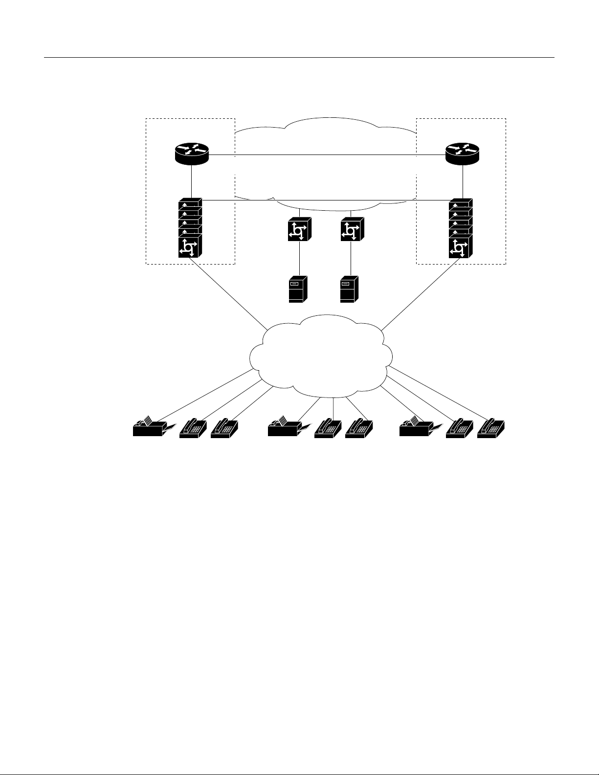
Figure 1 Two-Stage Dial Toll Bypass
Benefits
Gatekeeper
Zone A
Cisco
gatekeeper
RAS RAS
Cisco
gateway
Cisco
IP/PSTN
gateway
PRI PRI
Fax
server
QoS WAN
H.225/H.245 RTP
PRI
PSTN
RAS
gatekeeper
Cisco
gateway
PRI
Digital sound
voice mail
Gatekeeper
Zone B
Cisco
Cisco
IP/PSTN
gateway
PSTN Voice-Traffic and Fax-Traffic Off load
Carriers can leverage their WAN infrastructure to off load voice and fax traffic from their congested
PSTN networks by using the Cisco AS5800 as a carrier class voice gateway. In this application,
PSTN traffic designated to be off-loaded is forwarded to a tandem switch connected to the Cisco
AS5800 gateway. The AS5800 gateway then encapsulates the off-loaded PSTN traffic into RTP
streams and routes it across the WAN.
The signaling interface between the PSTN and the Cisco AS5800 can be either Common Channel
Signaling (CCS), with SS7 terminated by the VCO-4K service point or Channel Associated
Signaling (CAS), configured in Direct Inward Dial (DID) mode. Figure 2 illustrates this application.
13342
Voice over IP for the Cisco AS5800 3
Page 4
Feature Overview
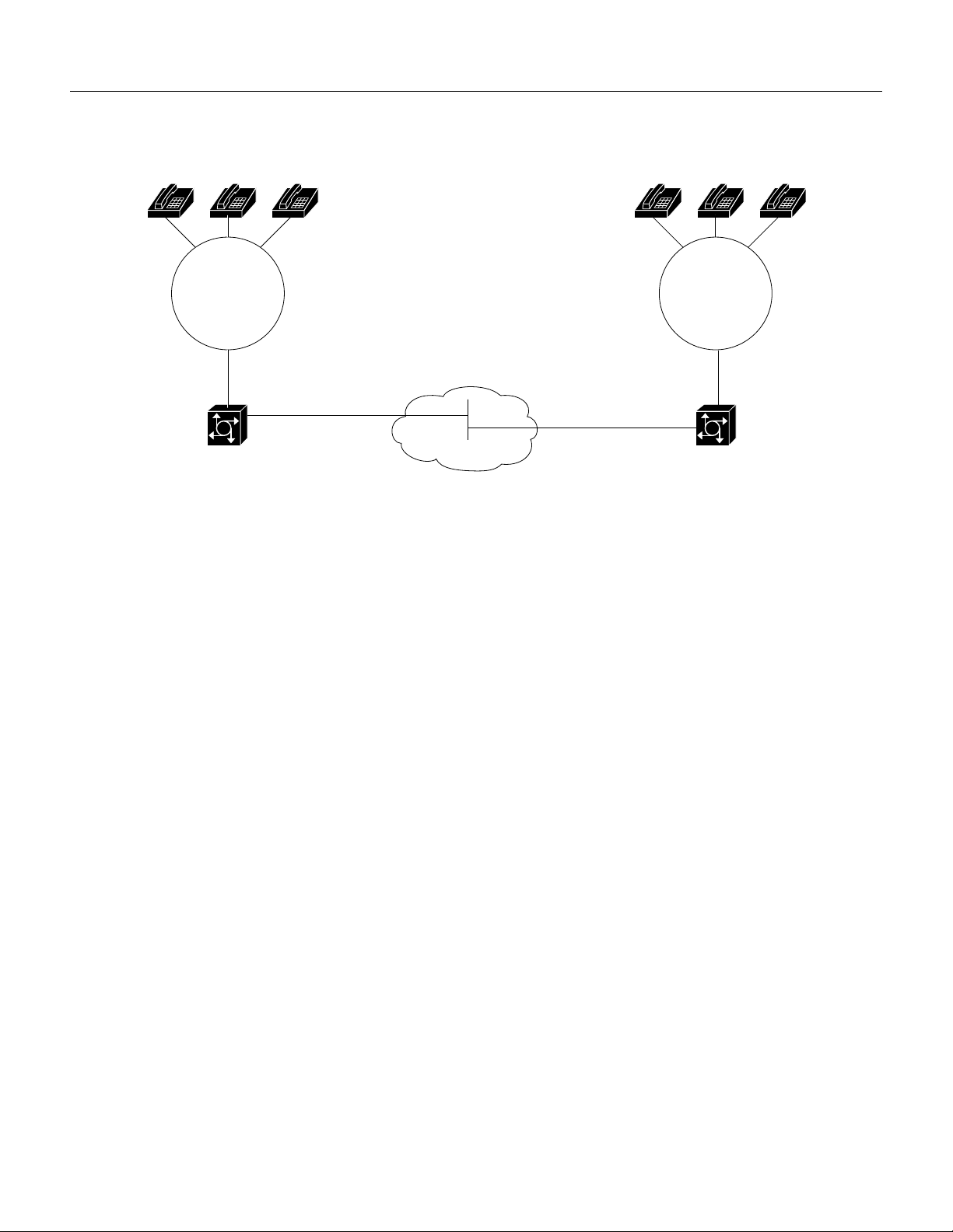
Figure 2 VoIP Used as a PSTN Gateway to Off load Voice Traffic and Fax Traffic
Local Exchange
Carrier
T1 ISDN
PRI
Cisco AS5800
Universally Accessible Voice-Mail and Fax-Mail Services
VoIP on the Cisco AS5800 can be used to leverage the technology prefixes feature. Gateways (with
voice/fax feature cards) that are connected to the voice-mail and fax-mail servers can be identified
by gatekeepers based on a prefix prepended to an E.164 telephone number.
Additional Benefits
VoIP on the Cisco AS5800 can be used to provide the following additional benefits:
WAN
Local Exchange
Carrier
T1 ISDN
PRI
Cisco AS5800
• Remote PBX presence over WANs
• POTS-Internet telephony gateways
30744
Restrictions
To run Voice over IP on the Cisco AS5800, the AS5800 must have a version of the Cisco IOS
software installed that supports DSDWare 3.1.7 (for example, Cisco IOS Release 12.0(4)XL or
Cisco IOS Release 12.0(7)T).
Related Features and Technologies
• Cisco IOS Release 12.0(3)T Voice over IP for the Cisco AS5300 feature module
• Cisco IOS Release 12.0(3)T Service Provider Features for Voice over IP feature module
• Cisco IOS Release 12.0(5)T IP RTP Priority feature module
• Cisco IOS Release 12.0(7)T Configuring Interactive Voice Response for Cisco Access Platforms
feature module
Related Documents
• Voice, Video, and Home Applications Configuration Guide, Cisco IOS Release 12.0
Cisco IOS Release 12.0(7)T
4
Page 5

• Voice, Video, and Home Applications Command Reference, Cisco IOS Release 12.0
• Quality of Service Configuration Guide, Cisco IOS Release 12.0
• Quality of Service Command Reference, Cisco IOS Release 12.0
• Voice over IP for the Cisco AS5800 Software Configuration Guide, Cisco IOS
Release 12.0(4)XL.
Supported Platforms
• Cisco AS5800 universal access servers
• Cisco AS5300 access servers
• Cisco 2600 series routers
• Cisco 3600 series routers
Supported Standards, MIBs, and RFCs
Supported Platforms
Standards
None
MIBs
• IF-MIB
• ENTITY-MIB.my
• CISCO-ENTITY-VENDORTYPE-OID-MIB.my
• DIAL-CONTROL-MIB.my
• CISCO-DIAL-CONTROL-MIB.my
• CISCO-VOICE-DIAL-CONTROL-MIB.my
• CISCO-VOICE-IF-MIB.my
• CISCO-DSP-MGMT-MIB.my
• CISCO-MMAIL-DIAL-CONTROL-MIB.my
• CISCO-CAS-IF-MIB.my
For descriptions of supported MIBs and how to use MIBs, see the Cisco MIB web site on CCO at
http://www.cisco.com/public/sw-center/netmgmt/cmtk/mibs.shtml.
RFCs
None
Voice over IP for the Cisco AS5800 5
Page 6

Prerequisites
Prerequisites
Before you can configure your Cisco AS5800 to use Voice over IP, you must first:
• Install a version of the Cisco IOS software that supports DSPWare 3.1.7 specific to the Cisco
AS5800 (for example, Cisco IOS Release 12.0(4)XL or Cisco IOS Release 12.0(7)T).
• Establish a working IP network. For more information about configuring IP, refer to the
“IP Overview,” “Configuring IP Addressing,” and “Configuring IP Services” chapters in the
Cisco IOS 12.0 Network Protocols Configuration Guide, Part 1.
• Complete basic configuration for the AS5800. This includes, as a minimum, the following tasks:
— Configure a host name and password for the AS5800
— Configure the Fast Ethernet interface of your AS5800 so that it can be recognized as a device
— Configure the AS5800 interfaces for ISDN PRI lines
— Configure the ISDN D channels for each ISDN PRI line
— Configure the AS5800 interfaces for T1 CAS lines
— Configure the ISDN D channels for each T1 CAS PRI line
on the Ethernet LAN
For more information about any of the these configuration tasks, refer to the Cisco AS5800
Universal Access Server Software Installation and Configuration Guide, which shipped with
your Cisco AS5800 and is available on the document CD-ROM.
• Install the VFC into the appropriate slot of your Cisco AS5800 universal access server. Each VFC
can hold up to 16 digital signal processor modules (DSPMs), enabling processing for up to 192
voice channels. For more information about the physical characteristics of the VFCs or DSPMs,
or how to install them, refer to Installing Voice over IP Feature Cards in Cisco AS5800 Universal
Access Servers document that shipped with your VFC and is available online.
• Complete your company’s dial plan.
• Establish a working telephony network based on your company’s dial plan.
Cisco IOS Release 12.0(7)T
6
Page 7

Configuration Tasks
• Integrate your dial plan and telephony network into your existing IP network topology. Merging
your IP and telephony networks depends on your particular IP and telephony network topology.
In general, we recommend the following suggestions:
— Use canonical numbers wherever possible. It is important that you avoid situations where
numbering systems are significantly different on different routers or access servers in your
network.
— Make routing and dialing transparent to the user. For example, avoid secondary dial tones
from secondary switches, where possible.
— Contact your PBX vendor for instructions about how to reconfigure the appropriate PBX
interfaces.
• Configure another device in your network (preferably a Cisco 2600 or Cisco 3600 series router)
to act as a gatekeeper. The Service Provider implementation of Voice over IP is configured using
both gatekeepers and gateways. Because of the extensive capabilities of the Cisco AS5800
universal access server, it is likely that it will function as a carrier class gateway in a Service
Provider environment. Unless it has a gatekeeper to interact with, it will periodically query all
devices in the network, searching for a gatekeeper. For more information about configuring
gatekeepers, refer to the Cisco IOS Release 12.0(3)T Service Provider Features for Voice over IP
feature module.
Configuration Tasks
After you have analyzed your dial plan and decided how to integrate it into your existing IP network,
you are ready to configure your network devices to support Voice over IP. The actual configuration
procedure depends entirely on the topology of your voice network, but, in general, you need to
complete the following tasks:
• Configuring IP Networks for Real-Time Voice Traffic
• Configuring Voice Ports
• Configuring Dial Peers
• Configuring the Cisco AS5800 as an H.323 Gateway
• Configuring the Cisco AS5800 for Interactive Voice Response
Configuring IP Networks for Real-Time Voice Traffic
You need to have a well-engineered network end-to-end when running delay-sensitive applications
such as VoIP. Fine-tuning your network to adequately support VoIP involves a series of protocols and
features geared toward Quality of Service (QoS). It is beyond the scope of this document to explain
the specific details relating to wide-scale QoS deployment. Cisco IOS software provides many tools
for enabling QoS on your backbone, such as Random Early Detection (RED), Weighted Random
Early Detection (WRED), Fancy Queuing (meaning custom, priority, or weighted fair queuing), and
IP Precedence. To configure your IP network for real-time voice traffic, you need to take into
consideration the entire scope of your network, then select the appropriate QoS tool or tools. In
addition, you must use the Cisco IOS ip cef command to ensure that Cisco Express Forwarding
(CEF) is enabled.
QoS must be configured throughout your network—not just on the Cisco AS5800 devices running
VoIP—to improve voice network performance. Not all QoS techniques are appropriate for all
network routers. Edge routers and backbone routers in your network do not necessarily perform the
Voice over IP for the Cisco AS5800 7
Page 8

Configuration Tasks
same operations; the QoS tasks they perform might also differ. To configure your IP network for
real-time voice traffic, you need to consider the functions of both edge and backbone routers in your
network, then select the appropriate QoS tool or tools.
In general, edge routers perform the following QoS functions:
• Packet classification
• Admission control
• Bandwidth management
• Queuing
In general, backbone routers perform the following QoS functions:
• High-speed switching and transport
• Congestion management
• Queue management
Scalable QoS solutions require cooperative edge and backbone functions.
Configuring Custom Queuing and IP RTP Reserve
Although not required, you can use the custom queuing QoS tool to fine-tune your network for
real-time voice traffic. Real-time voice traffic is carried on UDP ports ranging from 16384 to 32767.
Custom Queuing and other methods for identifying high priority streams should be configured for
these port ranges. For more information about custom queuing, refer to the “Congestion
Management” chapter in the Cisco IOS Release 12.0 Quality of Service Configuration Guide. For
more information about configuring IP RTP Priority, refer to the Cisco IOS Release 12.0(5)T IP RTP
Priority feature module.
Configuring Voice Ports
When an ISDN interface on the Cisco AS5800 is carrying voice data, it is referred to as a voice port.
Note A voice port was created automatically when you installed the VFC in the Cisco AS5800 and
configured an ISDN PRI group. Configuring an ISDN PRI group is part of the basic Cisco AS5800
configuration procedure. For more information, refer to the Cisco AS5800 Universal Access Server
Software Installation Configuration Guide.
Signaling in Voice over IP for the AS5800 is handled by ISDN PRI group configuration. After ISDN
PRI is configured for both B and D channels for both ISDN PRI lines, you need to issue the isdn
incoming-voice command on the serial interface (acting as the D channel) to ensure a dial tone.
Under most circumstances, the default voice-port command values are adequate to configure voice
ports to transport voice data over your existing IP network. Because of the inherent complexities
involved with PBX networks, you might need specific voice-port values configured, depending on
the specifications of the devices in your telephony network. For more information on specific
voice-port configuration commands, refer to either the Cisco IOS Release 12.0(3)T Voice over IP for
the Cisco AS5300 feature module or the Cisco IOS Release 12.0 Voice, Video, and Home
Applications Command Reference.
Cisco IOS Release 12.0(7)T
8
Page 9

To configure basic ISDN parameters for Voice over IP on the Cisco AS5800, perform the following
steps:
Step Command Purpose
1
2
3
4
5
6
7
8
9
10
11
12
13
Router(config)# isdn switch-type switch-type
Router(config)# controller T1 1/0/0
or
Router(config)# controller T1 1/0/0:1
Router(config)# framing esf
Router(config)# linecode value
Router(config)# pri-group timeslots range
Router(config)# controller T1 1/0/1
or
Router(config)# controller T1 1/0/0:2
Router(config)# framing esf
Router(config)# linecode value
Router(config)# pri-group timeslots range
Router(config)# interface Serial1/0/0:23
or
Router(config)# interface Serial1/0/0:1:23
Router(config)# isdn incoming-voice modem
Router(config)# interface Serial1/0/1:23
or
Router(config)# interface Serial1/0/0:2:23
Router(config)# isdn incoming-voice modem
Defines the telephone company’s switch type.
Enables the T1 0 controller on the T1 card and enters
controller configuration mode, or
Enables the T1 1 controller on the T3 card and enters
controller configuration mode.
Defines the framing characteristics.
Sets the line code type to match that of your telephone
company service provider.
Configures ISDN PRI.
Enables the T1 1 on the T1 card controller and enters
controller configuration mode, or
Enables the T1 2 controller on the T3 card and enters
controller configuration mode.
Defines the framing characteristics.
Sets the line code type to match that of your telephone
company service provider.
Configures ISDN PRI.
Configures the channel for the first ISDN PRI line on the
T1 card. (The ISDN serial interface is the D channel.) or
Configures the channel for the first ISDN PRI line on the
T3 card.
Enables incoming ISDN voice calls. This command has
two possible keywords: data and modem. You must use
the modem keyword to enable voice calls. The modem
keyword represents bearer capabilities of speech.
Configures the channel for the second ISDN PRI line.or
Configures the channel for the second ISDN PRI line on
the T3 card.
Enables incoming ISDN voice calls. This command has
two possible keywords: data and modem. You must use
the modem keyword to enable voice calls. The modem
keyword represents bearer capabilities of speech.
Configuring Voice Ports
As mentioned, under most circumstances, the default voice-port command values are adequate to
configure voice ports to transport voice data over your existing IP network. If you need to configure
specific voice port parameters, perform the following steps beginning in privileged EXEC mode:
Step Command Purpose
Router# configure terminal
1
Router(config)# voice-port {shelf/slot/port:D}|
2
{shelf/slot/parent:port:D}
Enters global configuration mode.
Identifies the voice port you want to configure and enters
voice-port configuration mode.
Voice over IP for the Cisco AS5800 9
Page 10

Configuration Tasks
Step Command Purpose
Router(config-voiceport)# cptone country
3
Selects the appropriate voice call progress tone for this
interface.
The default for this command is us. For a list of supported
countries, refer to the Multiservice Applications
Command Reference.
Router(config-voiceport)# compand-type {a-law|u-law}
4
Router(config-voiceport)# connection {plar string|trunk
5
string}
Selects a companding type for this voice port.
(Optional) Specifies either the trunk connection or the
private line auto ringdown (PLAR) connection. The string
value specifies the destination telephone number.
Router(config-voiceport)# music-threshold number
6
(Optional) Specifies the threshold (in decibels) for
on-hold music. Valid entries are from –70 to –30.
Router(config-voiceport)# description string
7
(Optional) Attaches descriptive text about this voice port
connection.
Fine-Tuning ISDN Voice Ports
Depending on the specifics of your particular network, you may need to adjust voice parameters
involving timing, input gain, and output attenuation for voice ports. Collectively, these commands
are referred to as voice-port tuning commands.
Note In most cases, the default values for voice-port tuning commands will be sufficient.
To fine-tune ISDN voice ports, use the following commands beginning in privileged EXEC mode:
Step Command Purpose
Router# configure terminal
1
Router(config)# voice-port {shelf/slot/port:D} |
2
{shelf/slot/parent:port:D}
Router(config-voiceport)# input gain value
3
Router(config-voiceport)# output attenuation value
4
Router(config-voiceport)# echo-canel enable
5
Router(config-voiceport)# echo-canel coverage value
6
Router(config-voiceport)# non-linear
7
Router(config-voiceport)# playout-delay {maximum
8
milliseconds|nominal milliseconds}
Router(config-voiceport)# timeouts initial seconds
9
Enters global configuration mode.
Identifies the voice port you want to configure and enter
voice-port configuration mode.
Specifies (in decibels) the amount of gain to be inserted at
the receiver side of the interface. Acceptable values are
from –6 to 14.
Specifies (in decibels) the amount of attenuation at the
transmit side of the interface. Acceptable values are from
0 to 14.
Enables echo-cancellation of voice that is sent out the
interface and received back on the same interface.
Adjusts the size (in milliseconds) of the echo-cancel.
Acceptable values are 16, 24, and 32.
Enables non-linear processing, which shuts off any signal
if no near-end speech is detected. (Non-linear processing
is used with echo-cancellation.)
Specifies the amount of time in milliseconds configured
for the playout delay buffer.
Specifies the number of seconds the system will wait for
the caller to input the first digit of the dialed digits. Valid
entries for this command are from 0 to 120.
Cisco IOS Release 12.0(7)T
10
Page 11

Step Command Purpose
Router(config-voiceport)# timeouts interdigits seconds
10
Router(config-voiceport)# timeouts ringing
11
{seconds|infinity}
Router(config-voiceport)# timeouts wait-release
12
{seconds|infinity}
Router(config-voiceport)# translate {called
13
number|calling number}
For more information on specific voice-port configuration commands or additional voice-port
commands, refer to either the Cisco IOS Release 12.0(3)T Voice over IP for the Cisco AS5300
feature module or the Cisco IOS Release 12.0 Voice, Video, and Home Applications Command
Reference..
Specifies the number of seconds the system will wait
(after the caller has input the initial digit) for the caller to
input a subsequent digit. Valid entries for this command
are from 0 to 120.
Specifies the number of seconds the system will continue
to ring the destination if there is no answer.
Specifies the wait release timeout duration in seconds.
Defines translation rules pertaining to either the called or
calling numbers.
Verifying Voice Port Configuration
• Use the show voice port command to verify that the data configured is correct.
Configuring Voice Ports
• If you have not configured your device to support direct inward dial, dial in to the router and see
if you have dial tone.
• Enter DTMF digit. If the dial tone stops, you have two-way voice connectivity with the router.
Troubleshooting Tips
If you are having trouble connecting a call, and you suspect the problem is associated with voice-port
configuration, you can try to resolve the problem by performing the following tasks:
• Ping the associated IP address to confirm connectivity. If you cannot successfully ping your
destination, refer to the “Configuring IP” chapter in the Cisco IOS 12.0 Network Protocols
Configuration Guide, Part 1.
• Check to see that the VFC has been correctly installed.
• Use the show dial-shelf command to see if the VFC is operational.
• Use the show vrm vdevices summary command to verify that you have voice devices available.
• Use the show isdn status command to view layer status information. If you receive a status
message stating that Layer 1 is deactivated, make sure the cable connection is not loose or
disconnected. (This status message indicates a problem at the physical layer.)
• With T1 lines, check to see if your u-law setting is correct. With E1 lines, check to see if your
a-law setting is correct. Use the cptone command to configure both a-law or u-law values. For
more information about the cptone command, refer to the Cisco IOS Release 12.0(3)T Voice over
IP for the Cisco AS5300 feature module.
• If dialing cannot occur, use the debug isdn q931 command to check the ISDN configuration.
Voice over IP for the Cisco AS5800 11
Page 12
Configuration Tasks
Configuring Dial Peers
The key point to understanding how VoIP functions is to understand dial peers. Each dial peer
defines the characteristics associated with a call leg, as shown in Figure 3 and Figure 4. A call leg is
a discrete segment of a call connection that lies between two points in the connection. All of the call
legs for a particular connection have the same connection ID.
There are two different kinds of dial peers:
• POTS—Dial peer describing the characteristics of a traditional telephony network connection.
POTS peers point to a particular voice port on a voice network device.
• VoIP—Dial peer describing the characteristics of a packet network connection. VoIP peers point
to specific VoIP devices.
An end-to-end call comprises four call legs, two from the perspective of the source access server as
shown in Figure 3, and two from the perspective of the destination access server as shown in
Figure 4. A dial peer is associated with each call leg. Dial peers are used to apply attributes to call
legs and to identify call origin and destination. Attributes applied to a call leg include QoS, codec,
VAD, and fax rate.
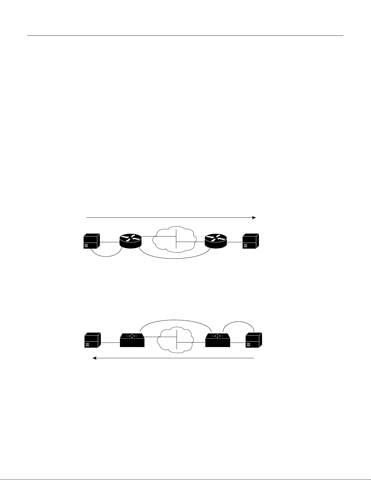
Figure 3 Dial Peer Call Legs from the Perspective of the Source Router
Source
Source router
Call leg for POTS
dial peer 1
Figure 4 Dial Peer Call Legs from the Perspective of the Destination Router
Destination
IP cloud
Call leg for VoIP
dial peer 2
Call leg for VoIP
dial peer 3
IP cloud
Call leg for POTS
Destination router
Destination
dial peer 4
Source
10353
10354
Inbound versus Outbound Dial Peers
Dial peers are used for both inbound and outbound call legs. It is important to remember that these
terms are defined from the access server’s perspective. An inbound call leg originates outside the
access server. An outbound call leg originates from the access server.
For inbound call legs, a dial peer might be associated to the calling number or the port designation.
Outbound call legs always have a dial peer associated with them. The destination pattern is used to
identify the outbound dial peer. The call is associated with the outbound dial peer at setup time.
Cisco IOS Release 12.0(7)T
12
Page 13

POTS peers associate a telephone number with a particular voice port so that incoming calls for that
telephone number can be received and outgoing calls can be placed. VoIP peers point to specific
devices (by associating destination telephone numbers with a specific IP address) so that incoming
calls can be received and outgoing calls can be placed. Both POTS and VoIP peers are needed to
establish VoIP connections.
Configuring POTS Peers
POTS peers enable incoming calls to be received by a particular telephony device. To configure a
POTS peer, you need to uniquely identify the peer (by assigning it a unique tag number), define its
telephone numbers, and associate it with a voice port through which calls will be established. Under
most circumstances, the default values for the remaining dial peer configuration commands will be
sufficient to establish connections.
To configure a POTS dial peer, use the following commands beginning in global configuration
mode:
Step Command Purpose
1
2
3
4
Router(config)# dial-peer voice
Router(config-dial-peer)# destination-pattern string
Router(config-dial-peer)# port shelf/slot/port:D
Router(config-dial-peer)# prefix string
number pots
Enters the dial peer configuration mode to configure a
POTS peer. The number value of the dial-peer voice
pots command is a tag that uniquely identifies the
dial peer.
Defines the telephone number associated with this POTS
dial peer.
Associates this POTS dial peer with a specific logical dial
interface.
(Optional) Specifies the prefix for this POTS dial peer.
The prefix string value is sent to the telephony interface
first, before the telephone number (destination pattern)
associated with this dial peer is sent.
Configuring Dial Peers
For additional POTS dial-peer configuration commands, refer to the “Voice-Related Commands”
section of the Cisco IOS Release 12.0 Voice, Video, and Home Applications Command Reference,
the Cisco IOS Release 12.0(3)T Voice over IP for the Cisco AS5300 feature module, and the Cisco
IOS Release 12.0(3)T Service Provider Features for Voice over IP feature module.
Outbound Dialing on POTS Peers
When a router receives a voice call, it selects an outbound dial peer by comparing the called number
(the full E.164 telephone number) in the call information with the number configured as the
destination pattern for the POTS peer. The router then strips out the left-justified numbers
corresponding to the destination pattern matching the called number. If you have configured a prefix,
the prefix will be put in front of the remaining numbers, creating a dial string, which the router will
then dial. If all numbers in the destination pattern are stripped-out, the user will receive (depending
on the attached equipment) a dial tone.
For example, suppose there is a voice call whose E.164 called number is 1 310 767-2222. If you
configure a destination-pattern of “1310767” and a prefix of “9,” the router will strip out “1310767”
from the E.164 telephone number, leaving the extension number of “2222.” It will then append the
Voice over IP for the Cisco AS5800 13
Page 14
Configuration Tasks
prefix, “9,” to the front of the remaining numbers, so that the actual numbers dialed is “9, 2222.” The
comma in this example means that the router will pause for one second between dialing the “9” and
the “2” to allow for a secondary dial tone.
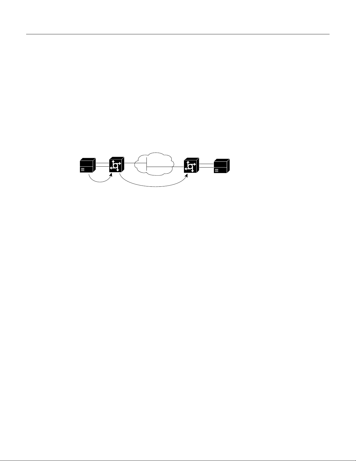
Direct Inward Dial for POTS Peers
Direct inward dial (DID) is used to determine how the called number is treated for incoming POTS
call legs. As shown in Figure 5, incoming means from the perspective of the router. In this case, it is
the call leg coming into the access server to be forwarded through to the appropriate destination
pattern.
Figure 5 Incoming and Outgoing POTS Call Legs
PBX
Unless otherwise configured, when a call arrives on the access server, the server presents a dial tone
to the caller and collects digits until it can identify the destination dial peer. After the dial peer is
identified, the call is forwarded through the next call leg to the destination.
There are cases where it might be necessary for the server to use the called-number (DNIS) to find
a dial peer for the outgoing call leg—for example, if the switch connecting the call to the server has
already collected the digits. DID enables the server to match the called-number with a dial peer and
then directly place the outbound call. With DID, the server does not present a dial tone to the caller
and does not collect digits; it forwards the call directly to the configured destination.
To use DID and incoming called-number, a dial peer must be associated with the incoming call leg.
Before doing this, it helps if you understand the logic behind the algorithm used to associate the
incoming call leg with the dial peer.
The algorithm used to associate incoming call legs with dial peers uses three inputs (which are
derived from signaling and interface information associated with the call) and four defined dial peer
elements. The three signaling inputs are:
Cisco AS5800
Incoming
call leg
IP
cloud
Outgoing
call leg
Cisco AS5800
PBX
22356
• Called-number (DNIS)—Set of numbers representing the destination, which is derived from the
ISDN setup message or CAS DNIS.
Cisco IOS Release 12.0(7)T
14
• Calling-number (ANI)—Set of numbers representing the origin, which is derived from the ISDN
setup message or CAS DNIS.
• Voice port—The voice port carrying the call.
The four defined dial peer elements are:
• Destination pattern—A pattern representing the phone numbers to which the peer can connect.
• Answer address—A pattern representing the phone numbers from which the peer can connect.
• Incoming called-number—A pattern representing the phone numbers that associate an incoming
call leg to a peer based on the called-number or DNIS.
• Port—The port through which calls to this peer are placed.
Page 15

Using the elements, the algorithm is as follows:
For all peers where call type (VoIP versus POTS) match dial peer type:
if the type is matched, associate the called number with the incoming called-number
else if the type is matched, associate calling-number with answer-address
else if the type is matched, associate calling-number with destination-pattern
else if the type is matched, associate voice port to port
This algorithm shows that if a value is not configured for answer-address, the origin address is used
because, in most cases, the origin address and answer-address are the same.
To configure a POTS dial peer for direct inward dial, use the following commands beginning in
global configuration mode:
Step Command Purpose
1
2
Router(config)# dial-peer voice number pots
Router(config-dial-peer)# direct-inward-dial
Note Direct inward dial is configured for the calling POTS dial peer.
Enters the dial peer configuration mode to configure a
POTS peer.
Specifies direct inward dial for this POTS peer.
Configuring Dial Peers
Distinguishing Voice and Modem Calls on the Cisco AS5800
When the Cisco AS5800 is handling both modem and voice calls, it needs to be able to identify the
service type of the call—that is, whether or not the incoming call to the server is a modem or a voice
call. When the access server handles only modem calls, the service type identification is handled
through modem pools. Modem pools associate calls with modem resources based on the
called-number (DNIS). In a mixed environment, where the server receives both modem and voice
calls, you need to identify the service type of a call by using the incoming called-number command.
Without this, the server attempts to resolve whether an incoming call is a modem or voice call based
on the interface over which the call comes. If the call comes in over an interface associated with a
modem pool, the call is assumed to be a modem call; if a call comes in over a voice port associated
with a dial peer, the call is assumed to be a voice call.
It helps to understand the logic behind the algorithm the system uses to distinguish voice and modem
calls. The algorithm is as follows:
If the called-number matches a number from the modem pool,
handle the call as a modem call
If the called-number matches a configured dial peer incoming called number,
handle the call as a voice call
Else handle the call as a modem call by default modem pool
If there is no called-number information configured, call classification is handled as follows:
If the interface matches the interface configured for the modem pool,
handle the call as a modem call.
If the voice port matches the one configured as the dial peer port,
handle the call as a voice call
Else handle the call as a modem call by default modem pool
To identify the service type of a call to be voice, use the following commands beginning in global
configuration mode:
Voice over IP for the Cisco AS5800 15
Page 16

Configuration Tasks
Step Command Purpose
1
2
Router(config)# dial-peer voice
Router(config-dial-peer)# incoming called-number
number
number pots
Enter the dial peer configuration mode to configure a
POTS peer.
Specify direct inward dial for this POTS peer.
Configuring VoIP Peers
VoIP peers enable outgoing calls to be made from a particular telephony device. To configure a VoIP
peer, you need to uniquely identify the peer (by assigning it a unique tag number), define its
destination telephone number and destination IP address. As with POTS peers, under most
circumstances, the default values for the remaining dial peer configuration commands will be
adequate to establish connections.
To configure a VoIP peer, use the following commands beginning in global configuration mode:
Step Command Purpose
1
2
3
4
Router(config)# dial-peer voice number voip
Router(config-dial-peer)# destination-pattern string
Router(config-dial-peer)# tech-prefix number
Router(config-dial-peer)# session-target
{ipv4:destination-address | dns:[$s$.|$d$.|$e$.|$u$.]
host-name|loopback:rtp|loopback:compressed|
loopback:unompressed|ras}
Enters the dial peer configuration mode to configure a
VoIP peer. The number value of the dial-peer voice voip
command is a tag that uniquely identifies the dial peer.
Defines the destination telephone number associated with
this VoIP dial peer.
Specifies that a particular technology prefix be prepended
to the destination patter of this dial peer.
Specifies a destination IP address for this dial peer.
For additional VoIP dial peer configuration options, refer to the “Voice-Related Commands” section
of the Cisco IOS Release 12.0 Voice, Video, and Home Applications Command Reference, the Cisco
IOS Release 12.0(3)T Voice over IP for the Cisco AS5300 feature module, and the Cisco IOS Release
12.0(3)T Service Provider Features for Voice over IP feature module.
Verifying Dial Peer Configuration
If you have relatively few dial peers configured, you can use the show dial-peer voice command
•
to verify that the data configured is correct. Use this command to display a specific dial peer or
to display all configured dial peers.
• Use the show dialplan number command to show the dial peer to which a particular number
(destination pattern) resolves.
Troubleshooting Tips
• Ping the associated IP address to confirm connectivity. If you cannot successfully ping your
destination, refer to the chapter, “Configuring IP,” in the Cisco IOS 11.3 Network Protocols
Configuration Guide, Part 1.
• Use the show dial-peer voice command to verify that the operational status of the dial peer is up.
Cisco IOS Release 12.0(7)T
16
Page 17

Configuring the Cisco AS5800 as an H.323 Gateway
• Use the show dialplan number command on the local and remote routers to verify that the data
is configured correctly on both.
• If you have configured number expansion, use the show num-exp command to check that the
partial number on the local router maps to the correct full E.164 telephone number on the remote
router.
• If you have configured a CODEC value, there can be a problem if both VoIP dial peers on either
side of the connection have incompatible CODEC values. Make sure that both VoIP peers have
been configured with the same CODEC value.
• Use the debug voip ccani inout command to verify the output string the router dials is correct.
• Use the debug cch323 rtp command to check RTP packet transport.
• Use the debug cch323 h245 command to check logical channel negotiation.
• Use the debug cch323 h225 command to check the call setup.
Configuring the Cisco AS5800 as an H.323 Gateway
The Service Provider implementation of Voice over IP uses both gatekeepers and gateways. Because
of the extensive capabilities of the Cisco AS5800 universal access server, it is likely that it will
function as a carrier class gateway in a Service Provider environment. The final step in configuring
the Cisco AS5800 for Voice over IP functionality is to configure one of its interfaces as a gateway
interface. You can use either an interface that is connected to the gatekeeper or a loopback interface
for the gateway interface. The interface that is connected to the gatekeeper is usually a LAN
interface—Fast Ethernet, Ethernet, FDDI, or Token Ring.
To configure a gateway interface, perform the following steps beginning in the global configuration
mode:
Step Command Purpose
1
2
3 Configure the interface. This step will vary, depending on
4
5
6
7
8
Router(config)# gateway
Router(config)# ip cef
Router(config)# int fa0
Router(config-if)# h323-gateway voip interface
Router(config-if)# h323-gateway voip id gatekeeper-id
{ipaddr ip-address [port-number]|multicast}
Router(config-if)# h323-gateway voip h323-id
interface-id
Router(config-if) h323-gateway voip tech-prefix prefix
Enables the gateway.
Enables Cisco Express Routing.
the interface you select as being the interface connected to
the gatekeeper. For the purposes of this procedure, a Fast
Ethernet interface is used.
Enters configuration mode for the configured Fast
Ethernet interface connected to the gatekeeper.
Identifies this interface as a VoIP gateway interface.
Defines the name and location of the gatekeeper for this
gateway.
Defines the H.323 name of the gateway, identifying this
gateway to its associated gatekeeper.
Defines the technology prefix that the gateway will
register with the gatekeeper.
For more information about configuring gateways and gatekeepers, refer to the Cisco IOS Release
12.0(3)T Service Provider Features for Voice over IP feature module.
Voice over IP for the Cisco AS5800 17
Page 18

Configuration Tasks
Verifying Gateway Interface Configuration
Use the show gateway command to find the current registration information and status of the
gateway.
Configuring the Cisco AS5800 for Interactive Voice Response
The Interactive Voice Response (IVR) Service Provider application provides IVR capabilities using
Tool Command Language (TCL) scripts. For example, an IVR script is played when a caller receives
a voice-prompt instruction to enter a specific type of information, such as a PIN. After playing the
voice prompt, the IVR application collects the predetermined number of touch tones (digit
collection) and forwards the collected digits to a server for storage and retrieval. Call records can be
kept, and a variety of accounting functions performed.
Available IVR Scripts
The following is a description of the available IVR scripts:
• fax_hop_on_1—Collects digits from the redialer, such as account number and destination
number. When placing the call to the H.323 network, the set of fields configured in the call
information structure are entered, destination, and account.
• clid_authen—Authenticates the call with Automatic Number Identification (ANI) and Dialed
• clid_authen_npw—Same as clid_authen, but uses a null password when authenticating, rather
• clid_authen_collect—Authenticates the call with ANI and DNIS and collects the destination
• clid_authen_col_npw—Same as clid_authen_collect, but uses a null password and does not
• clid_col_npw_3—Same as clid_authen_col_npw except if authentication with the digits
Configuring IVR
To use IVR with scripts, you need to configure the inbound POTS dial peer to support IVR, as well
as enable IVR functionality by using the call application global configuration. To configure IVR, use
the following commands beginning in the global configuration mode:
Number Identification Service (DNIS), collects the destination data, and makes the call.
than DNIS.
data, but if authentication fails, it collects the account and password.
use or collect DNIS.
collected (account and PIN number) failed, the script clid_authen_col_npw just played a failure
message (auth_failed.au) and then hung up. This script, clid_col_npw_3 allows two failures,
then plays the retry audio file (auth_retry.au) and collects the account and PIN numbers again
The caller can interrupt the message by entering digits for the account number which will trigger
the prompt to enter the PIN number. If authentication fails the third time, the script plays the
audio file auth_fail_final.au, then hangs up.
Step Command Purpose
1
2
3
18
Router (config)# call application voice name
Router(config)# dial-peer voice number pots
Router(config-dial-peer)# application name
Cisco IOS Release 12.0(7)T
Creates and then calls the application that interacts with
the IVR feature.
Enters the dial peer configuration mode to configure a
POTS peer.
Selects an IVR session application for the dial peer to use.
Page 19
Step Command Purpose
r
4
5
6
Router(config-dial-peer)# destination-pattern string
Router(config-dial-peer)# port shelf/slot/port:D
Router(config-dial-peer)# prefix string
Defines the telephone number associated with this POTS
dial peer.
Associates this POTS dial peer with a specific logical dial
interface.
(Optional) Specifies the prefix for this POTS dial peer.
The prefix string value is sent to the telephony interface
first, before the telephone number (destination pattern)
associated with this dial peer is sent.
For more information about configuring IVR, refer to the Cisco IOS Release 12.0(7)T Configuring
Interactive Voice Response for Cisco Access Platforms feature module.
Verifying IVR Configuration
• If you have relatively few dial peers configured, you can use the show dial-peer voice command
to verify that the data configured is correct. Use this command to display a specific dial peer or
to display all configured dial peers.
• Use the show running configuration command to show all configured parameters relating to
IVR.
Configuration Example
Configuration Example
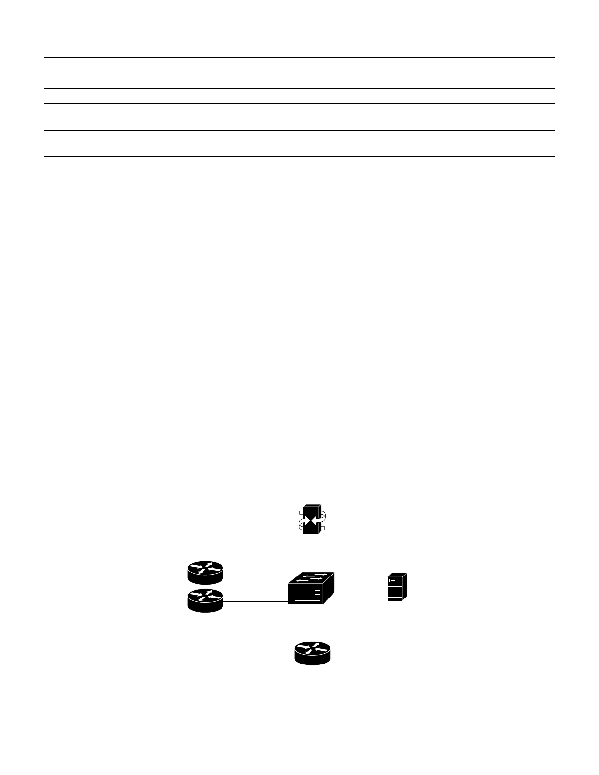
The following configuration example shows an abbreviated configuration using a Cisco 2600 router
and a CiscoAS5800 universal access server as gateways and a Cisco 3600 router as a gatekeeper.
Figure 6 shows the network diagram for this particular scenario.
Figure 6 AS5800 Universal Access Server Acting as a Gateway
Cisco 2600
Cisco 2600
10BASE-T
10BASE-T
AS5800 VoIP
H.323 gateway
5000
Catalyst
5000
Cisco 3640
gatekeeper
100BASE-T
10BASE-T
NT Server
Cisco CallManage
10BASE-T
30460
Voice over IP for the Cisco AS5800 19
Page 20

Configuration Example
Configuring the Cisco 3640 as a Gatekeeper
! Configure the Ethernet interface to be used at the gatekeeper interface.
interface Ethernet0/1
ip address 172.30.00.00 255.255.255.0
no ip directed-broadcast
no logging event link-status
no keepalive
!
! Configure the gatekeeper interface and enable the interface.
gatekeeper
zone local gk3.gg-dn1 gg-dn1 173.50.00.00
zone prefix gk3.gg-dn1 21*
gw-type-prefix 9#* gw ipaddr 173.60.0.0 1720
gw-type-prefix 6#* gw ipaddr 173.60.0.199 1720
no use-proxy gk3.gg-dn1 default inbound-to terminal
no shutdown
!
Configuring the Cisco 2600 as a Gateway
! Configure POTS and VoIP dial peers.
dial-peer voice 88 voip
destination-pattern 11111
tech-prefix 9#
session ras
!
dial-peer voice 11 pots
incoming called-number 11111
destination-pattern 6#12345
port 1/1/1
prefix 12345
!
! Configure the gateway interface.
interface Ethernet0/0
ip address 173.60.0.199 255.255.255.0
no ip directed-broadcast
no ip mroute-cache
no logging event link-status
no keepalive
no cdp enabled
h323-gateway voip interface
h323-gateway voip id gk3.gg-dn1 ipaddr 173.30.0.0 1719
h323-gateway voip h323-id gw6@gg-dn1
h323-gateway voip tech-prefix 6#
!
Configuring the Cisco AS5800 as a Gateway
! Configure the T1 controller. (This configuration is for a T3 card.)
controller T1 1/0/0:1
framing esf
linecode b8zs
pri-group timeslots 1-24
!
! Configure POTS and VoIP dial peers.
dial-peer voice 11111 pots
incoming called-number 12345
destination-pattern 9#11111
direct-inward-dial
port 1/0/0:1:D
prefix 11111
Cisco IOS Release 12.0(7)T
20
Page 21

Command Reference
!
dial-peer voice 12345 voip
destination-pattern 12345
tech-prefix 6#
session target ras
!
! Enable gateway functionality.
gateway
!
! Enable Cisco Express Forwarding.
ip cef
!
! Configure and enable the gateway interface.
interface FastEthernet0/3/0
ip address 173.60.0.0.255.255.255.0
no ip directed-broadcast
no keepalive
full-duplex
no cdp enable
h323-gateway voip interface
h323-gateway voip id gk3.gg-dn1 ipaddr 173.30.0.0 1719
h323-gateway voip h323-id gw3@gg-dn1
h323-gateway voip tech-prefix 9#
!
! Configure the serial interface.(This configuration is for a T3 serial interface.)
interface Serial1/0/0:1:23
no ip address
no ip directed-broadcast
ip mroute-cache
isdn switch-type primary-5ess
isdn incoming-voice modem
no cdp enable
Command Reference
This section documents new or modified commands. All other commands used with this feature are
documented in one of the following Cisco IOS documentation:
• Cisco IOS Release 12.0 Voice, Video, and Home Applications Command Reference
• Cisco IOS Release 12.0 Dial Solutions Command Reference
• Cisco IOS Release 12.0(3)T Voice over IP for the AS5300 feature module
• Cisco IOS Release 12.0(3)T Service Provider Features for Voice over IP feature module
• Cisco IOS Release 12.0(7)T Configuring Interactive Voice Response for Cisco Access Platforms
feature module
New Commands
• dtmf-relay
• show vrm vdevice
• show vrm active_calls
• test vrm busyout
• test vrm reset
• test vrm unbusyout
Voice over IP for the Cisco AS5800 21
Page 22

Command Reference
Modified Commands
• codec
• port
• show csm
• show voice port
• voice-port
In Cisco IOS Release 12.0(1)T or later, you can search and filter the output for show and more
commands. This functionality is useful when you need to sort through large amounts of output, or if
you want to exclude output that you do not need to see.
To use this functionality, enter a show or more command followed by the “pipe” character (|), one
of the keywords begin, include, or exclude, and an expression that you want to search or filter on:
command | {begin | include | exclude} regular-expression
Following is an example of the show atm vc command in which you want the command output to
begin with the first line where the expression “PeakRate” appears:
show atm vc | begin PeakRate
For more information on the search and filter functionality, refer to the Cisco IOS Release 12.0(1)T
feature module titled CLI String Search.
Cisco IOS Release 12.0(7)T
22
Page 23

codec
Syntax Description
codec
To specify the voice coder rate of speech for a dial peer, use the codec dial-peer configuration
command. To restore the default voice coder rate of speech value, use the no form of this command.
codec {g711alaw | g711ulaw | g723r53 | g723r63 | g726r16 | g726r24 | g726r32 |
g728 | g729abr8 | g729ar8 | g729br8 | g729r8 | gsmfr}
no codec
g711alaw G.711 A-Law 64000 bits per second (bps).
g711ulaw G.711 u-Law 64000 bps.
g723r53 G.723.1 5300 bps.
g723r63 G.723.1 6300 bps.
g726r16 G.726 16000 bps.
Defaults
Command Modes
g726r24 G.726 24000 bps.
g726r32 G.726 32000 bps.
g728 G.728 16000 bps.
g729abr8 G.729 ANNEX-A & B 8000 bps.
g729ar8 G.729 ANNEX-A 8000 bps.
g729br8 G.729 ANNEX-B 8000 bps.
g729r8 G.729 8000 bps.
gsmfr GSMFR 13200 bps.
g729r8.
Dial-peer configuration
Voice over IP for the Cisco AS5800 23
Page 24

Command Reference
Command History
Usage Guidelines
Examples
Release Modification
11.3(1)T This command was introduced.
11.3(3)T Support for Cisco 2600 series routers was added.
12.0(3)T Support for the Cisco AS5300 access server was added.
12.0(7)T Additional voice coder rates of speech were added.
For toll quality, use the g711alaw or g711ulaw values. These values provide high-quality voice
transmission but use a significant amount of bandwidth. For almost toll quality (and a significant
savings in bandwidth), use the g729r8 value.
If codec values for the VoIP peers of a connection do not match, the call will fail.
This command is only applicable to VoIP peers.
The following example configures a voice coder rate that provides toll quality but uses a relatively
high amount of bandwidth:
dial-peer voice 10 voip
codec g711alaw
Related Commands
Command Description
dtmf-relay Specifies how an H.323 gateway relays DTMF tones between telephony
interfaces and an IP network.
Cisco IOS Release 12.0(7)T
24
Page 25

dtmf-relay
Syntax Description
dtmf-relay
To specify how an H.323 gateway relays dual tone multifrequency (DTMF) tones between telephony
interfaces and an IP network, use the dtmf-relay dial-peer configuration command. To remove all
signaling options and transmit the DTMF tones as part of the audio stream, use the no form of this
command.
dtmf-relay [cisco-rtp] [h245-alphanumeric] [h245-signal]
no dtmf-relay
cisco-rtp (Optional) Forwards DTMF tones by using RTP protocol with a
Cisco proprietary payload type.
h245-alphanumeric (Optional) Forwards DTMF tones by using the H.245
“alphanumeric” User Input Indication method. Supports tones
0-9, *, #, and A-D.
h245-signal (Optional) Forwards DTMF tones by using the H.245 “signal”
User Input Indication method. Supports tones 0-9, *, #, and
A-D.
Defaults
Command Modes
Command History
Usage Guidelines
No default behavior or values.
Dial-peer configuration
Release Modification
12.0(7)T This command was introduced.
DTMF is the tone generated when you press a digit on a touch-tone phone. This tone is compressed
at one end of a call; when the tone is decompressed at the other end, it can become distorted,
depending on the codec used. The DTMF relay feature transports DTMF tones generated after call
establishment out of band using a standard H.323 out-of-band method and a proprietary RTP-based
mechanism.
The gateway sends DTMF tones in the format you specify only if the remote device supports it. If
the remote device supports multiple formats, the gateway chooses the format based on the following
priority:
• cisco-rtp (highest priority)
• none, meaning that the DTMF is sent in-band
Voice over IP for the Cisco AS5800 25
Page 26

Command Reference
Examples
The principal advantage of the dtmf-relay command is that it transmits DTMF tones with greater
fidelity than is possible in-band for most low-bandwidth CODECs, such as G.729 and G.723.
Without the use of DTMF relay, calls established with low-bandwidth CODECs may have trouble
accessing automated DTMF-based systems, such as voice-mail, menu-based ACD systems, and
automated banking systems.
Note The cisco-rtp option of the dtmf-relay command is a proprietary Cisco implementation and
only operates between two Cisco AS5800 universal access servers running Cisco IOS Release
12.0(2)XH, or between Cisco AS5800 universal access servers or Cisco 2600 or 3600 modular
access routers running Cisco IOS Release 12.0(2)XH or later releases. Otherwise, the DTMF relay
feature does not function, and the gateway sends DTMF tones in-band.
The following example configures DTMF relay with the cisco-rtp option when sending DTMF
tones to dial-peer 103:
5800# configure terminal
5800(config)# dial-peer voice 103 voip
5800(config-dial-peer)# dtmf-relay cisco-rtp
5800(config-dial-peer)# end
5800#
Related Commands
The next example configures the gateway to send DTMF in-band (the default) when sending DTMF
tones to dial-peer 103:
5800# configure terminal
5800(config)# dial-peer voice 103 voip
5800(config-dial-peer)# no dtmf-relay
5800(config-dial-peer)# end
Command Description
codec
Specifies the voice coder rate of speech for a dial peer.
Cisco IOS Release 12.0(7)T
26
Page 27

port
port
To associate a dial peer with a specific voice port, use the port dial peer configuration command. To
cancel this association, use the no form of this command.
Cisco 2600/3600 Series Router
port slot/subunit/port
no port
Cisco MC3810
port slot/port
no port
Cisco AS5300 Access Server
port controller number:D
no port
Syntax Description
Cisco AS5800 Access Server
port {shelf/slot/port:D} | {shelf/slot/parent:port:D}
no port
controller number:D Specifies the T1 or E1 controller; :D indicates the D channel associated
with ISDN PRI. Valid entries for the controller number variable is 0 to 3.
shelf/slot/port:D Specifies the T1 or E1 controller on the T1 card; :D indicates the
D-channel associated with ISDN PRI. Valid entries for the shelf variable
is 0 to 9999. Valid entries for the slot variable is 0 to 11. Valid entries for
the port variable is 0 to 11.
shelf/slot/parent:port:D Specifies the T1 controller on the T3 card; :D indicates the D-channel
associated with ISDN PRI. Valid entries for the shelf variable is 0 to
9999. Valid entries for the slot variable is 0 to 11. Valid entries for the
port variable is 1 to 28. The value for the parent variable is always 0.
port Specifies the voice port number. Valid entries are 0 or 1.
slot Specifies the slot number where the voice interface card is installed.
Valid entries are 0 or 1.
Default
subunit Specifies the subunit on the voice interface card in the router where the
voice port is located. Valid entries are 0 or 1.
No port is configured.
Voice over IP for the Cisco AS5800 27
Page 28

Command Reference
Command Mode
Command History
Usage Guidelines
Dial-peer configuration
Release Modification
11.3(1)T This command was introduced (Cisco 3600 series router).
11.3(3)T Port-specific values for the Cisco 2600 were added.
11.3 MA Port-specific values for the Cisco MC3810 were added.
12.0(3)T Port-specific values for the Cisco AS5300 were added.
12.0(7)T Port-specific values for the Cisco AS5800 were added.
This command is used for calls incoming from a telephony interface to select an incoming dial peer
and for calls coming from the VoIP network to match a port with the selected outgoing dial peer.
This command applies only to POTS peers.
Example
The following example associates a Cisco 3600 series router POTS dial peer 10 with voice port 1,
which is located on subunit 0, and accessed through port 0:
dial-peer voice 10 pots
port 1/0/0
The following example associates a Cisco MC3810 POTS dial peer 10 with voice port 0, which is
located in slot 1:
dial-peer voice 10 pots
port 1/0
The following example associates a Cisco AS5300 POTS dial peer 10 with voice port 0:D:
dial-peer voice 10 pots
port 0:D
The following example associates a Cisco AS5800 POTS dial peer 10 with voice port 1/0/0:D
(T1 card):
dial-peer voice 10 pots
port 1/0/0:D
The following example associates a Cisco AS5800 POTS dial peer 10 with voice port 1/0/0:1:D
(T3 card):
dial-peer voice 10 pots
port 1/0/0:1:D
Cisco IOS Release 12.0(7)T
28
Page 29

show csm
Syntax Description
show csm
To display the call switching module (CSM) statistics for a particular or all DSP channels or for a
specific modem or DSP channel, use the show csm privileged EXEC command.
Cisco AS5300 Access Server
show csm {modem [slot/port | modem-group-number] | voice [slot/dspm/dsp/dsp-channel]}
Cisco AS5800 Universal Access Server
show csm voice [shelf/slot/port]
modem Specifies CSM call statistics for modems.
voice Specifies CSM call statistics for DSP channels.
slot/port (Optional) Specifies the location (and thereby the identity) of a specific
modem.
Defaults
Command Modes
Command History
modem-group-number (Optional) Displays configuration for the dial peer identified by the
argument number. Valid entries are any integers that identify a specific
dial peer, from 1 to 32767.
slot/dspm/dsp/dsp-channel (Optional) Identifies the location of a particular DSP channel.
shelf/slot/port (Optional) Identifies the location of the voice interface card.
No default behavior or values.
Privileged EXEC
Release Modification
11.3 NA This command was introduced.
12.0(3)T Port-specific values for the Cisco AS5300 were added.
12.0(7)T Port-specific values for the Cisco AS5800 were added.
Usage Guidelines
This command shows the information related to CSM, which includes the DSP channel, the start
time of the call, the end time of the call, and the channel on the controller used by the call.
Voice over IP for the Cisco AS5800 29
Page 30

Command Reference
Examples
Use the show csm modem command to display the CSM call statistic information for a specific
modem, for a group of modems, or for all modems. If a slot/port argument is specified, then CSM
call statistics are displayed for the specified modem. If the modem-group-number argument is
specified, the CSM call statistics for all of the modems associated with that modem group are
displayed. If no keyword is specified, CSM call statistics for all modems on the AS5300 are
displayed.
Use the show csm voice command to display CSM statistics for a particular DSP channel. If the
slot/dspm/dsp/dsp-channel or shelf/slot/port argument is specified, the CSM call statistics for calls
using the identified DSP channel will be displayed. If no argument is specified, all CSM call
statistics for all DSP channels will be displayed.
The following is sample output from the Cisco AS5300 for the show csm voice command:
Router# show csm voice 2/4/4/0
slot 2, dspm 4, dsp 4, dsp channel 0,
slot 2, port 56, tone, device_status(0x0002): VDEV_STATUS_ACTIVE_CALL.
csm_state(0x0406)=CSM_OC6_CONNECTED, csm_event_proc=0x600E2678, current call thru PRI
line
invalid_event_count=0, wdt_timeout_count=0
wdt_timestamp_started is not activated
wait_for_dialing:False, wait_for_bchan:False
pri_chnl=TDM_PRI_STREAM(s0, u0, c22), tdm_chnl=TDM_DSP_STREAM(s2, c27)
dchan_idb_start_index=0, dchan_idb_index=0, call_id=0xA003, bchan_num=22
csm_event=CSM_EVENT_ISDN_CONNECTED, cause=0x0000
ring_no_answer=0, ic_failure=0, ic_complete=0
dial_failure=0, oc_failure=0, oc_complete=3
oc_busy=0, oc_no_dial_tone=0, oc_dial_timeout=0
remote_link_disc=0, stat_busyout=0
oobp_failure=0
call_duration_started=00:06:53, call_duration_ended=00:00:00,
total_call_duration=00:00:44
The calling party phone number = 408
The called party phone number = 5271086
total_free_rbs_timeslot = 0, total_busy_rbs_timeslot = 0,
total_dynamic_busy_rbs_timeslot = 0, total_static_busy_rbs_timeslot = 0,
total_sw56_rbs_timeslot = 0, total_sw56_rbs_static_bo_ts = 0,
total_free_isdn_channels = 21, total_busy_isdn_channels =
0,total_auto_busy_isdn_channels = 0,
min_free_device_threshold = 0
Cisco IOS Release 12.0(7)T
30
Page 31

The following is sample output from the Cisco AS5800 for the show csm voice command:
5800# show csm voice 1/8/19
shelf 1, slot 8, port 19
VDEV_INFO:slot 8, port 19
vdev_status(0x00000401):VDEV_STATUS_ACTIVE_CALL.VDEV_STATUS_HASLOCK.
csm_state(0x00000406)=CSM_OC6_CONNECTED, csm_event_proc=0x60868B8C, current
call thru PRI line
invalid_event_count=0, wdt_timeout_count=0
watchdog timer is not activated
wait_for_bchan:False
pri_chnl=(T1 1/0/0:22), vdev_chnl=(s8, c19)
start_chan_p=0, chan_p=62436D58, call_id=0x800D, bchan_num=22
The calling party phone number =
The called party phone number = 7511
ring_no_answer=0, ic_failure=0, ic_complete=0
dial_failure=0, oc_failure=0, oc_complete=1
oc_busy=0, oc_no_dial_tone=0, oc_dial_timeout=0
remote_link_disc=0, busyout=0, modem_reset=0
call_duration_started=3d16h, call_duration_ended=00:00:00,
total_call_duration=00:00:00
Table 1 explains the fields contained in both of these examples.
show csm
Table 1 show csm voice Field Descriptions
Field Description
slot Indicates the slot where the VFC resides.
shelf/slot/port Specifies the T1 or E1 controller.
dspm/dsp/dsp channel Indicates which DSP channel is engaged in this call.
dsp Indicates the DSP through which this call is established.
slot/port This is the logical port number for the device. This is equivalent to the DSP
channel number. The port number is derived from:
(max_number_of_dsp_channels per dspm=12) * the dspm # (0-based) +
(max_number_of_dsp_channels per dsp=2) * the dsp # (0-based) +
the dsp channel number (0-based).
tone Indicates which signalling tone is being used (DTMF, MF, R2). This only
applies to CAS calls. Possible values are:
—mf
—dtmf
— r2-compelled
— r2-semi-compelled
— r2-non-compelled
Voice over IP for the Cisco AS5800 31
Page 32

Command Reference
Table 1 show csm voice Field Descriptions (continued)
Field Description
device_status The status of the device. Possible values are:
— VDEV_STATUS_UNLOCKED—Device is unlocked (meaning that it is
available for new calls).
— VDEV_STATUS_ACTIVE_WDT—Device is allocated for a call and the
watchdog timer is set to time the connection response from the central
office.
— VDEV_STATUS_ACTIVE_CALL—Device is engaged in an active,
connected call.
— VDEV_STATUS_BUSYOUT_REQ—Device is requested to busyout;
does not apply to voice devices.
— VDEV_STATUS_BAD—Device is marked as bad and not usable for
processing calls.
— VDEV_STATUS_BACK2BACK_TEST—Modem is performing
back-to-back testing (for modem calls only).
— VDEV_STATUS_RESET—Modem needs to be reset (for modem only).
— VDEV_STATUS_DOWNLOAD_FILE—Modem is downloading a file
(for modem only).
— VDEV_STATUS_DOWNLOAD_FAIL—Modem has failed during
downloading a file (for modem only).
— VDEV_STATUS_SHUTDOWN—Modem is not powered up (for modem
only).
— VDEV_STATUS_BUSY—Modem is busy (for modem only).
— VDEV_STATUS_DOWNLOAD_REQ—Modem is requesting
connection (for modem only).
Cisco IOS Release 12.0(7)T
32
Page 33

show csm
Table 1 show csm voice Field Descriptions (continued)
Field Description
csm_state CSM call state of the current call (PRI line) associated with this device. Possible
values are:
— CSM_IDLE_STATE—Device is idle.
— CSM_IC_STATE—A device has been assigned to an incoming call.
— CSM_IC1_COLLECT_ADDR_INFO—A device has been selected to
perform ANI/DNIS address collection for this call. ANI/DNIS address
information collection is in progress. The ANI/DNIS is used to decide
whether the call should be processed by a modem or a voice DSP.
— CSM_IC2_RINGING—The device assigned to this incoming call has
been told to get ready for the call.
— CSM_IC3_WAIT_FOR_SWITCH_OVER—A new device is selected to
take over this incoming call from the device collecting the ANI/DNIS
address information.
— CSM_IC4_WAIT_FOR_CARRIER—This call is waiting for the
CONNECT message from the carrier.
— CSM_IC5_CONNECTED—This incoming call is connected to the
central office.
— CSM_IC6_DISCONNECTING—This incoming call is waiting for a
DISCONNECT message from the VTSP module to complete the
disconnect process.
— CSM_OC_STATE —An outgoing call is initiated.
— CSM_OC1_REQUEST_DIGIT—The device is requesting the first digit
for the dial-out number.
— CSM_OC2_COLLECT_1ST_DIGIT—The first digit for the dial-out
number has been collected.
— CSM_OC3_COLLECT_ALL_DIGIT—All the digits for the dial-out
number have been collected.
— CSM_OC4_DIALING—This call is waiting for a dsx0 (B channel) to be
available for dialing out.
— CSM_OC5_WAIT_FOR_CARRIER—This (outgoing) call is waiting for
the central office to connect.
— CSM_OC6_CONNECTED—This (outgoing) call is connected.
— CSM_OC7_BUSY_ERROR—A busy tone has been sent to the device
(for VoIP call, no busy tone is sent; just a DISCONNECT INDICATION
message is sent to the VTSP module) and this call is waiting for a
DISCONNECT message from the VTSP module (or ONHOOK message
from the modem) to complete the disconnect process.
— CSM_OC8_DISCONNECTING—The central office has disconnected
this (outgoing) call and the call is waiting for a DISCONNECT message
from the VTSP module to complete the disconnect process.
csm_state: invalid_event_count= Number of invalid events received by the CSM state machine.
wdt_timeout_count= Number of times the watchdog timer is activated for this call.
wdt_timestamp_started Indicates whether the watchdog timer is activated for this call.
wait_for_dialing: Indicates whether this (outgoing) call is waiting for a free digit collector to
become available to dial out the outgoing digits.
Voice over IP for the Cisco AS5800 33
Page 34

Command Reference
Table 1 show csm voice Field Descriptions (continued)
Field Description
wait_for_bchan: Indicates whether this (outgoing) call is waiting for a B channel to send the call
out on.
pri_chnl= Indicates which type of TDM stream is used for the PRI connection. For PRI
and CAS calls, it will always be TDM_PRI_STREAM.
tdm_chnl= Indicates which type of TDM stream is used for the connection to the device
used to process this call. In the case of a VoIP call, this will always be set to
TDM_DSP_STREAM.
dchan_idb_start_index= First index to use when searching for the next IDB of a free D channel.
dchan_idb_index= Index of the currently available IDB of a free D channel.
csm_event= Event just passed to the CSM state machine.
cause Event cause.
ring_no_answer= Number of times call failed because there was no response.
ic_failure= Number of failed incoming calls.
ic_complete= Number of successful incoming calls.
dial_failure= Number of times the connection failed because there was no dial tone.
oc_failure= Number of failed outgoing calls.
oc_complete= Number of successful outgoing calls.
oc_busy= Number of outgoing calls where the connection failed because there was a busy
signal.
oc_no_dial_tone= Number of outgoing calls where the connection failed because there was no dial
tone.
oc_dial_timeout= Number of outgoing calls where the connection failed because the timeout value
was exceeded.
call_duration_started= Indicates the start of this call.
call_duration_ended= Indicates the end of this call.
total_call_duration= Indicates the duration of this call.
The calling party phone number = Calling party number as given to CSM by ISDN.
The called party phone number = Called party number as given to CSM by ISDN.
total_free_rbs_timeslot = Total number of free RBS (CAS) timeslots available for the whole system.
total_busy_rbs_timeslot = Total number of RBS (CAS) timeslots that have been busied out. This includes
both dynamically and statically busied out RBS timeslots.
total_dynamic_busy_rbs_
timeslot =
total_static_busy_rbs_timeslot = Total number of RBS (CAS) timeslots that have been statically busied out (that
total_free_isdn_channels = Total number of free ISDN channels.
total_busy_isdn_channels = Total number of busy ISDN channels.
total_auto_busy_isdn_channels = Total number of ISDN channels that are automatically busied out.
Total number of RBS (CAS) timeslots that have been dynamically busied out.
is, they are busied out using the CLI command)
Cisco IOS Release 12.0(7)T
34
Page 35

Related Commands
show csm
Command Description
show call active voice Displays the Voice over IP active call table.
show call history voice Displays the Voice over IP call history table.
show num-exp Displays how the number expansions are configured in Voice over IP.
show voice port Displays configuration information about a specific voice port.
Voice over IP for the Cisco AS5800 35
Page 36

Command Reference
show voice port
To display configuration information about a specific voice port, use the show voice port privileged
EXEC command.
Cisco 2600/3600 Series Router
show voice port slot-number/subunit-number/port
Cisco MC3810
show voice port [slot/port] [summary]
Cisco AS5300 Access Router
show voice port controller number:D
Cisco AS5800 Universal Access Router
show voice port {shelf/slot/port:D} | {shelf/slot/parent:port:D}
Syntax Description
For the Cisco 2600/3600 series:
slot-number Slot number in the Cisco router where the voice interface card is
installed. Valid entries are from 0 to 3, depending on the slot where it has
been installed.
subunit-number Subunit on the voice interface card where the voice port is located. Valid
entries are 0 or 1.
port Voice port number. Valid entries are 0 or 1.
Cisco IOS Release 12.0(7)T
36
Page 37

show voice port
For the Cisco MC3810:
slot/port (Optional) Displays information for only the voice port you specify with
the slot/port designation.
The slot variable specifies the slot number in the Cisco router where the
voice interface card is installed. The only valid entry is 1.
The port variable specifies the voice port number. Valid ranges are as
follows:
Analog voice ports: from 1 to 6.
Digital voice port:
Digital T1: from 1 to 24.
Digital E1: from 1 to 15, and from 17 to 31.
summary (Optional) Display a summary of all voice ports.
For the Cisco AS5300 Access Server:
controller number Specifies the T1 or E1 controller.
Command Mode
:D Indicates the D channel associated with ISDN PRI.
For the Cisco AS5800 Universal Access Server:
shelf/slot/port Specifies the T1 or E1 controller on the T1 card.Valid entries for the shelf
variable is 0 to 9999. Valid entries for the slot variable is 0 to 11. Valid
entries for the port value is 0 to 11.
shelf/slot/parent:port Specifies the T1 controller on the T3 card. Valid entries for the shelf
variable is 0 to 9999. Valid entries for the slot variable is 0 to 11. Valid
entries for the port variable is 1 to 28. The value for the parent variable is
always 0.
:D Indicates the D channel associated with ISDN PRI.
Privileged EXEC
Voice over IP for the Cisco AS5800 37
Page 38

Command Reference
Command History
Usage Guidelines
Examples
Release Modification
11.3(1)T This command was introduced.
11.3 MA Port-specific values for the Cisco MC3810 were added.
12.0(3)T Port-specific values for the Cisco AS5300 were added.
12.0(7)T Port-specific values for the Cisco AS5800 were added.
This command applies to Voice over IP, Voice over Frame Relay, Voice over ATM, and Voice over
HDLC.
Use the show voice port privileged EXEC command to display configuration and voice interface
card-specific information about a specific port.
The following is sample output from the show voice port command for an E&M voice port on the
Cisco 3600 series:
router# show voice port 1/0/0
E&M Slot is 1, Sub-unit is 0, Port is 0
Type of VoicePort is E&M
Operation State is unknown
Administrative State is unknown
The Interface Down Failure Cause is 0
Alias is NULL
Noise Regeneration is disabled
Non Linear Processing is disabled
Music On Hold Threshold is Set to 0 dBm
In Gain is Set to 0 dB
Out Attenuation is Set to 0 dB
Echo Cancellation is disabled
Echo Cancel Coverage is set to 16ms
Connection Mode is Normal
Connection Number is
Initial Time Out is set to 0 s
Interdigit Time Out is set to 0 s
Analog Info Follows:
Region Tone is set for northamerica
Currently processing none
Maintenance Mode Set to None (not in mtc mode)
Number of signaling protocol errors are 0
Voice card specific Info Follows:
Signal Type is wink-start
Operation Type is 2-wire
Impedance is set to 600r Ohm
E&M Type is unknown
Dial Type is dtmf
In Seizure is inactive
Out Seizure is inactive
Digit Duration Timing is set to 0 ms
InterDigit Duration Timing is set to 0 ms
Pulse Rate Timing is set to 0 pulses/second
InterDigit Pulse Duration Timing is set to 0 ms
Clear Wait Duration Timing is set to 0 ms
Wink Wait Duration Timing is set to 0 ms
Cisco IOS Release 12.0(7)T
38
Page 39

show voice port
Wink Duration Timing is set to 0 ms
Delay Start Timing is set to 0 ms
Delay Duration Timing is set to 0 ms
The following is sample output from the show voice port command for an FXS voice port on the
Cisco 3600 series:
router# show voice port 1/0/0
Foreign Exchange Station 1/0/0 Slot is 1, Sub-unit is 0, Port is 0
Type of VoicePort is FXS
Operation State is DORMANT
Administrative State is UP
The Interface Down Failure Cause is 0
Alias is NULL
Noise Regeneration is enabled
Non Linear Processing is enabled
Music On Hold Threshold is Set to 0 dBm
In Gain is Set to 0 dB
Out Attenuation is Set to 0 dB
Echo Cancellation is enabled
Echo Cancel Coverage is set to 16ms
Connection Mode is Normal
Connection Number is
Initial Time Out is set to 10 s
Interdigit Time Out is set to 10 s
Analog Info Follows:
Region Tone is set for northamerica
Currently processing none
Maintenance Mode Set to None (not in mtc mode)
Number of signaling protocol errors are 0
Voice card specific Info Follows:
Signal Type is loopStart
Ring Frequency is 25 Hz
Hook Status is On Hook
Ring Active Status is inactive
Ring Ground Status is inactive
Tip Ground Status is inactive
Digit Duration Timing is set to 100 ms
InterDigit Duration Timing is set to 100 ms
Hook Flash Duration Timing is set to 600 ms
The following is sample output from the show voice port command for an FXS voice port on the
Cisco MC3810:
router# show voice port 1/2
Voice port 1/2 Slot is 1, Port is 2
Type of VoicePort is FXS
Operation State is UP
Administrative State is UP
No Interface Down Failure
Description is not set
Noise Regeneration is enabled
Non Linear Processing is enabled
In Gain is Set to 0 dB
Out Attenuation is Set to 0 dB
Echo Cancellation is enabled
Echo Cancel Coverage is set to 8 ms
Connection Mode is normal
Connection Number is not set
Initial Time Out is set to 10 s
Interdigit Time Out is set to 10 s
Coder Type is g729ar8
Companding Type is u-law
Voice over IP for the Cisco AS5800 39
Page 40

Command Reference
Voice Activity Detection is disabled
Ringing Time Out is 180 s
Wait Release Time Out is 30 s
Nominal Playout Delay is 80 milliseconds
Maximum Playout Delay is 160 milliseconds
Analog Info Follows:
Region Tone is set for northamerica
Currently processing Voice
Maintenance Mode Set to None (not in mtc mode)
Number of signaling protocol errors are 0
Impedance is set to 600r Ohm
Analog interface A-D gain offset = -3 dB
Analog interface D-A gain offset = -3 dB
Voice card specific Info Follows:
Signal Type is loopStart
Ring Frequency is 20 Hz
Hook Status is On Hook
Ring Active Status is inactive
Ring Ground Status is inactive
Tip Ground Status is active
Digit Duration Timing is set to 100 ms
InterDigit Duration Timing is set to 100 ms
Ring Cadence are [20 40] * 100 msec
InterDigit Pulse Duration Timing is set to 500 ms
The following is sample output from the show voice port summary command for all voice ports on
a Cisco MC3810 with an analog voice module (AVM):
router# show voice port summary
IN OUT ECHO
PORT SIG-TYPE ADMIN OPER IN-STATUS OUT-STATUS CODEC VAD GAIN ATTN CANCEL
1/1 fxs-ls up up on-hook idle 729a n 0 0 y
1/2 fxs-ls up up on-hook idle 729a n 0 0 y
1/3 e&m-wnk up up idle idle 729a n 0 0 y
1/4 e&m-wnk up up idle idle 729a n 0 0 y
1/5 fxo-ls up up idle on-hook 729a n 0 0 y
1/6 fxo-ls up up idle on-hook 729a n 0 0 y
Table 2 explains the fields in the sample output.
Table 2 show voice port Field Descriptions
Field Description
Administrative State Administrative state of the voice port.
Alias User-supplied alias for this voice port.
Analog interface A-D gain offset Offset of the gain for analog-to-digital conversion.
Analog interface D-A gain offset Offset of the gain for digital-to-analog conversion.
Clear Wait Duration Timing Time of inactive seizure signal to declare call cleared.
Coder Type Voice compression mode used.
Companding Type Companding standard used to convert between analog and digital signals in
PCM systems.
Connection Mode Connection mode of the interface.
Connection Number Full E.164 telephone number used to establish a connection with the trunk or
PLAR mode.
Cisco IOS Release 12.0(7)T
40
Page 41

show voice port
Table 2 show voice port Field Descriptions (continued)
Field Description
Currently Processing Type of call currently being processed: none, voice, or fax.
Delay Duration Timing Maximum delay signal duration for delay dial signaling.
Delay Start Timing Timing of generation of delayed start signal from detection of incoming
seizure.
Description Description of the voice port.
Dial Type Out-dialing type of the voice port.
Digit Duration Timing DTMF digit duration in milliseconds.
E&M Type Type of E&M interface.
Echo Cancel Coverage Echo cancel coverage for this port.
Echo Cancellation Whether or not echo cancellation is enabled for this port.
Hook Flash Duration Timing Maximum length of hook flash signal.
Hook Status Hook status of the FXO/FXS interface.
Impedance Configured terminating impedance for the E&M interface.
In Gain Amount of gain inserted at the receiver side of the interface.
In Seizure Incoming seizure state of the E&M interface.
Initial Time Out Amount of time the system waits for an initial input digit from the caller.
InterDigit Duration Timing DTMF interdigit duration in milliseconds.
InterDigit Pulse Duration Timing Pulse dialing interdigit timing in milliseconds.
Interdigit Time Out Amount of time the system waits for a subsequent input digit from the caller.
Maintenance Mode Maintenance mode of the voice port.
Maximum Playout Delay The amount of time before the Cisco MC3810 DSP starts to discard voice
packets from the DSP buffer.
Music On Hold Threshold Configured music-on-hold threshold value for this interface.
Noise Regeneration Whether or not background noise should be played to fill silent gaps if VAD is
activated.
Nominal Playout Delay The amount of time the Cisco MC3810 DSP waits before starting to play out
the voice packets from the DSP buffer.
Non-Linear Processing Whether or not non-linear processing is enabled for this port.
Number of signaling protocol errors Number of signaling protocol errors.
Operations State Operation state of the port.
Operation Type Operation of the E&M signal: two-wire or four-wire.
Out Attenuation Amount of attenuation inserted at the transmit side of the interface.
Out Seizure Outgoing seizure state of the E&M interface.
Port Port number for this interface associated with the voice interface card.
Pulse Rate Timing Pulse dialing rate in pulses per second (pps).
Region Tone Configured regional tone for this interface.
Ring Active Status Ring active indication.
Ring Cadence Configured ring cadence for this interface.
Ring Frequency Configured ring frequency for this interface.
Voice over IP for the Cisco AS5800 41
Page 42

Command Reference
Table 2 show voice port Field Descriptions (continued)
Field Description
Ring Ground Status Ring ground indication.
Ringing Time Out Ringing time out duration.
Signal Type Type of signaling for a voice port: loop-start, ground-start, wink-start,
immediate, and delay-dial.
Slot Slot used in the voice interface card for this port.
Sub-unit Subunit used in the voice interface card for this port.
Tip Ground Status Tip ground indication.
Type of VoicePort Type of voice port: FXO, FXS, and E&M.
The Interface Down Failure Cause Text string describing why the interface is down,
Voice Activity Detection Whether Voice Activity Detection is enabled or disabled.
Wait Release Time Out The time that a voice port stays in the call-failure state while the Cisco
MC3810 sends a busy tone, reorder tone, or an out-of-service tone to the port.
Wink Duration Timing Maximum wink duration for wink start signaling.
Wink Wait Duration Timing Maximum wink wait duration for wink start signaling.
The following is sample output from the Cisco AS5800 for the show voice port command:
5800# show voice port 1/0/0:D
ISDN 1/0/0:D
Type of VoicePort is ISDN
Operation State is DORMANT
Administrative State is UP
No Interface Down Failure
Description is ""
Noise Regeneration is enabled
Non Linear Processing is enabled
Music On Hold Threshold is Set to -38 dBm
In Gain is Set to 0 dB
Out Attenuation is Set to 0 dB
Echo Cancellation is enabled
Echo Cancel Coverage is set to 16 ms
Connection Mode is normal
Connection Number is not set
Initial Time Out is set to 10 s
Interdigit Time Out is set to 10 s
Region Tone is set for US
Table 3 explains the fields in the sample output.
Table 3 show voice port Field Descriptions for the Cisco AS5800
Field Description
Type of VoicePort Indicates the voice port type.
Operational State Operational state of the voice port.
Administrative State Administrative state of the voice port.
Clear Wait Duration Timing Time of inactive seizure signal to declare call cleared.
Currently Processing Type of call currently being processed: none, voice, or fax.
Cisco IOS Release 12.0(7)T
42
Page 43

show voice port
Table 3 show voice port Field Descriptions for the Cisco AS5800 (continued)
Field Description
Operations State Operation state of the port.
Operation Type Operation of the E&M signal: two-wire or four-wire.
Noise Regeneration Whether or not background noise should be played to fill silent gaps if VAD is
activated.
Non-Linear Processing Whether or not non-linear processing is enabled for this port.
Music-On-Hold Threshold Configured music-on-hold threshold value for this interface.
In Gain Amount of gain inserted at the receiver side of the interface.
Out Attenuation Amount of attenuation inserted at the transmit side of the interface.
Pulse Rate Timing Pulse dialing rate in pulses per second (pps).
Echo Cancellation Whether or not echo cancellation is enabled for this port.
Echo Cancel Coverage Echo Cancel Coverage for this port.
Connection Mode Connection mode of the interface.
Connection Number Full E.164 telephone number used to establish a connection with the trunk or
PLAR mode.
Initial Time Out Amount of time the system waits for an initial input digit from the caller.
Interdigit Time Out Amount of time the system waits for a subsequent input digit from the caller.
Regional Tone Configured regional tone for this interface.
Related Commands
Command Description
show call active voice Displays the Voice over IP active call table.
show call history voice Displays the Voice over IP call history table.
show dial-peer voice Displays configuration information for dial peers.
show voice port Displays configuration information about a specific voice port.
Voice over IP for the Cisco AS5800 43
Page 44

Command Reference
show vrm active_calls
To display active-only voice calls either for a specific VFC or all VFCs, use the
show vrm active_calls privileged EXEC command.
show vrm active_calls {dial-shelf-slot-number | all}
Syntax Description
dial shelf slot number Slot number of the dial shelf. Valid number is 0 to 13.
all Lists all active calls for VFC slots.
Defaults
No default behavior or values.
Command Modes
Privileged EXEC
Command History
Usage Guidelines
Examples
Release Modification
12.0(7)T This command was introduced.
Use the show vrm active_calls to display active-only voice calls either for a specific VFC or all
VFCs. Each active call occupies a block of information describing the call. This information
provides basically the same information as the show vrm vdevice command.
The following is sample output from the show vrm active_calls command specifying dial shelf slot
number:
5800# show vrm active_calls 6
slot = 6 virtual voice dev (tag) = 61 channel id = 2
capabilities list map = 9FFF
last/current codec loaded/used = None
TDM timeslot = 241
Resource (vdev_common) status = 401 means :active others
tot ingress data = 24
tot ingress control = 1308
tot ingress data drops = 0
tot ingress control drops = 0
tot egress data = 22051
tot egress control = 1304
tot egress data drops = 0
tot egress control drops = 0
Cisco IOS Release 12.0(7)T
44
Page 45

show vrm active_calls
slot = 6 virtual voice dev (tag) = 40 channel id = 2
capabilities list map = 9FFF
last/current codec loaded/used = None
TDM timeslot = 157
Resource (vdev_common) status = 401 means :active others
Table 4 explains the fields in the sample output.
Table 4 show vrm vdevice Field Descriptions
Field Description
slot Slot where voice card is installed.
virtual voice dev (tag) Identification number of the virtual voice device.
channel id Identification number of the channel associated with this virtual voice device.
capability list map Bitmaps for the codec supported on that DSP channel. Available values are:
• CC_CAP_CODEC_G711U: 0x1
• CC_CAP_CODEC_G711A: 0x2
• CC_CAP_CODEC_G729IETF: 0x4
• CC_CAP_CODEC_G729a: 0x8
• CC_CAP_CODEC_G726r16: 0x10
• CC_CAP_CODEC_G726r24: 0x20
• CC_CAP_CODEC_G726r32: 0x40
• CC_CAP_CODEC_G728: 0x80
• CC_CAP_CODEC_G723r63: 0x100
• CC_CAP_CODEC_G723r53: 0x200
• CC_CAP_CODEC_GSM: 0x400
• CC_CAP_CODEC_G729b: 0x800
• CC_CAP_CODEC_G729ab: 0x1000
• CC_CAP_CODEC_G723ar63: 0x2000
• CC_CAP_CODEC_G723ar53: 0x4000
• CC_CAP_CODEC_G729: 0x8000
last/current codec loaded/used Indicates the last codec loaded or used.
TDM timeslot Time division multiplexing timeslot.
Resource (vdev_common) status Current status of the VFC.
tot ingress data Total amount of data (number of packets) sent from the PSTN side of the
connection to the VoIP side of the connection.
tot ingress control Total number of control packets sent from the PSTN side of the connection to
the VoIP side of the connection.
tot ingress data drops Total number of data packets dropped from the PSTN side of the connection
to the VoIP side of the connection.
tot ingress control drops Total number of control packets dropped from the PSTN side of the
connection to the VoIP side of the connection.
tot egress data Total amount of data (number of packets) sent from the VoIP side of the
connection to the PSTN side of the connection.
Voice over IP for the Cisco AS5800 45
Page 46

Command Reference
Related Commands
Table 4 show vrm vdevice Field Descriptions (continued)
Field Description
tot egress control Total number of control packets sent from the VoIP side of the connection to
the PSTN side of the connection.
tot egress data drops Total number of data packets dropped from the VoIP side of the connection to
the PSTN side of the connection.
tot egress control drops Total number of control packets dropped from the VoIP side of the connection
to the PSTN side of the connection.
Command Description
show vrm vdevices Displays detailed information for a specific DSP or a brief summary display for
all VFCs.
Cisco IOS Release 12.0(7)T
46
Page 47

show vrm vdevices
To display detailed information for a specific DSP or a brief summary display for all VFCs, use the
show vrm vdevices privileged EXEC command.
show vrm vdevices {{vfc-slot-number | voice-device-number} | summary}
Syntax Description
vfc-slot-number Slot number of the VFC. Valid number is 0 to 11.
voice-device-number DSP number. Valid number is 1 to 96.
summary List synopsis of voice feature card DSP mappings, capabilities, and
Defaults
No default behavior or values.
show vrm vdevices
resource states.
Command Modes
Command History
Usage Guidelines
Privileged EXEC
Release Modification
12.0(7)T This command was introduced.
Use the show vrm vdevice to display detailed information for a specific DSP or a brief summary
display for all VFCs. The display provides information on the number of channels, channels per
DSP, bitmap of DSPMs, version numbers, and so on. This information is useful in monitoring the
current state of your VFCs.
The display for a specific DSP provides information on the codec that each channel is using, if active,
or last used and if the channel is not currently transmitting cells. It also displays the state of the
resource. In most cases, if there is an active call on that channel, the resource should be marked
active. If the resource is marked as reset and/or bad, this may be an indication of a response loss for
the VFC on a reset request. If this condition persists, you might experience a problem with the
communication link between the router shelf and the VFC.
Voice over IP for the Cisco AS5800 47
Page 48

Command Reference
Examples
The following is sample output from the show vrm vdevice command specifying dial shelf slot
number and DSP number. In this particular example, the call is active so the statistics displayed are
for this active call. If no calls are currently active on the device, the statistics would be for the
previous (or last active) call.
5800# show vrm vdevices 6 1
slot = 6 virtual voice dev (tag) = 1 channel id = 1
capabilities list map = 9FFF
last/current codec loaded/used = None
TDM timeslot = 0
Resource (vdev_common) status = 401 means :active others
tot ingress data = 101
tot ingress control = 1194
tot ingress data drops = 0
tot ingress control drops = 0
tot egress data = 39722
tot egress control = 1209
tot egress data drops = 0
tot egress control drops = 0
slot = 6 virtual voice dev (tag) = 1 channel id = 2
capabilities list map = 9FFF
last/current codec loaded/used = None
TDM timeslot = 1
Resource (vdev_common) status = 401 means :active others
tot ingress data = 21
tot ingress control = 1167
tot ingress data drops = 0
tot ingress control drops = 0
tot egress data = 19476
tot egress control = 1163
tot egress data drops = 0
tot egress control drops = 0
Table 5 explains the fields in the sample output.
Table 5 show vrm vdevice Field Descriptions
Field Description
slot Slot where voice card is installed.
virtual voice dev (tag) Identification number of the virtual voice device.
channel id Identification number of the channel associated with this virtual voice device.
Cisco IOS Release 12.0(7)T
48
Page 49

show vrm vdevices
Table 5 show vrm vdevice Field Descriptions (continued)
Field Description
capability list map Bitmaps for the codec supported on that DSP channel. Available values are:
• CC_CAP_CODEC_G711U: 0x1
• CC_CAP_CODEC_G711A: 0x2
• CC_CAP_CODEC_G729IETF: 0x4
• CC_CAP_CODEC_G729a: 0x8
• CC_CAP_CODEC_G726r16: 0x10
• CC_CAP_CODEC_G726r24: 0x20
• CC_CAP_CODEC_G726r32: 0x40
• CC_CAP_CODEC_G728: 0x80
• CC_CAP_CODEC_G723r63: 0x100
• CC_CAP_CODEC_G723r53: 0x200
• CC_CAP_CODEC_GSM: 0x400
• CC_CAP_CODEC_G729b: 0x800
• CC_CAP_CODEC_G729ab: 0x1000
• CC_CAP_CODEC_G723ar63: 0x2000
• CC_CAP_CODEC_G723ar53: 0x4000
• CC_CAP_CODEC_G729: 0x8000
last/current codec loaded/used Indicates the last codec loaded or used.
TDM timeslot Time division multiplexing timeslot.
Resource (vdev_common) status Current status of the VFC. Possible field values are:
• FREE = 0x0000
• ACTIVE_CALL = 0x0001
• BUSYOUT_REQ = 0x0002
• BAD = 0x0004
• BACK2BACK_TEST = 0x0008
• RESET = 0x0010
• DOWNLOAD_FILE = 0x0020
• DOWNLOAD_FAIL = 0x0040
• SHUTDOWN = 0x0080
• BUSY = 0x0100
• OIR = 0x0200
• HASLOCK = 0x0400 /* vdev_pool has locked port */
• DOWNLOAD_REQ = 0x0800
• RECOVERY_REQ = 0x1000
• NEGOTIATED = 0x2000
• OOS = 0x4000
tot ingress data Total amount of data (number of packets) sent from the PSTN side of the
connection to the VoIP side of the connection.
tot ingress control Total number of control packets sent from the PSTN side of the connection to
the VoIP side of the connection.
Voice over IP for the Cisco AS5800 49
Page 50

Command Reference
Table 5 show vrm vdevice Field Descriptions (continued)
Field Description
tot ingress data drops Total number of data packets dropped from the PSTN side of the connection
to the VoIP side of the connection.
tot ingress control drops Total number of control packets dropped from the PSTN side of the
connection to the VoIP side of the connection.
tot egress data Total amount of data (number of packets) sent from the VoIP side of the
connection to the PSTN side of the connection.
tot egress control Total number of control packets sent from the VoIP side of the connection to
the PSTN side of the connection.
tot egress data drops Total number of data packets dropped from the VoIP side of the connection to
the PSTN side of the connection.
tot egress control drops Total number of control packets dropped from the VoIP side of the connection
to the PSTN side of the connection.
The following is sample output from the show vrm devices command specifying a summary list. In
the Voice Device Mapping area, the C_Ac column indicates number of active calls for a specific
DSP. If there are any non zero numbers under the C_Rst and/or C_Bad column, this indicates a reset
request was sent but it was lost; this could mean a faulty DSP.
5800# show vrm vdevices summary
***********************************************************
******summary of voice devices for all voice cards*********
***********************************************************
slot = 6 major ver = 0 minor ver = 1 core type used = 2
number of modules = 16 number of voice devices (DSPs) = 96
chans per vdevice = 2 tot chans = 192 tot active calls = 178
module presense bit map = FFFF tdm mode = 1 num_of_tdm_timeslots = 384
auto recovery is on
number of default voice file (core type images) = 2
file 0 maj ver = 0 min ver = 0 core_type = 1
trough size = 2880 slop value = 0 built-in codec bitmap = 0
loadable codec bitmap = 0 fax codec bitmap = 0
file 1 maj ver = 3 min ver = 1 core_type = 2
trough size = 2880 slop value = 1440 built-in codec bitmap = 40B
loadable codec bitmap = BFC fax codec bitmap = 7E
-------------------Voice Device Mapping-----------------------Logical Device (Tag) Module# DSP# C_Ac C_Busy C_Rst C_Bad
--------------------------------------------------------------1 1 1 2 0 0 0
2 1 2 2 0 0 0
3 1 3 2 0 0 0
4 1 4 2 0 0 0
5 1 5 2 0 0 0
6 1 6 2 0 0 0
+++++++++++++++++++++++++++++++++++++++++++++++++++++++++++
7 2 1 2 0 0 0
8 2 2 2 0 0 0
9 2 3 2 0 0 0
10 2 4 1 0 0 0
11 2 5 2 0 0 0
12 2 6 1 0 0 0
+++++++++++++++++++++++++++++++++++++++++++++++++++++++++++
Cisco IOS Release 12.0(7)T
50
Page 51

show vrm vdevices
<information deleted>
+++++++++++++++++++++++++++++++++++++++++++++++++++++++++++
91 16 1 2 0 0 0
92 16 2 2 0 0 0
93 16 3 1 0 0 0
94 16 4 2 0 0 0
95 16 5 2 0 0 0
96 16 6 2 0 0 0
+++++++++++++++++++++++++++++++++++++++++++++++++++++++++++
Total active call channels = 178
Total busied out channels = 0
Total channels in reset = 0
Total bad channels = 0
Note :Channels could be in multiple states
Table 6 explains the fields in the sample output.
Table 6 show vrm vdevice summary Field Descriptions
Field Description
slot Slot number where VFC is installed.
major ver Major version of firmware running on VFC.
minor ver Minor version of firmware running on VFC.
core type used Type of DSPware in use. Possible field values are:
• 1 = UBL (boot loader)
• 2 = high complexity core
• 3 = medium complexity core
• 4 = low complexity core
• 255 = invalid.
number of modules Number of modules on the VFC. Maximum number possible is 16.
number of voice devices (DSP)s Number of possible DSPs. Maximum number is 96.
chans per vdevice Number of channels (meaning calls) each DSP can handle.
tot chans Total number of channels.
tot active calls Total number of active calls on this VFC.
module presense bit map Indicates a 16-bit bitmap, each bit representing a module.
tdm mode Time division multiplex bus mode. Possibe field values are:
• 0 = VFC is in classic mode
• 1 = VFC is in plus mode.
This field should always be 1.
num_of_tdm_timeslots Total number of calls that can be handled by the VFC.
auto recovery Indicates whether auto recovery is enabled. When autorecovery is enabled,
the VRM will try to recover a DSP by resetting it if, for some reason, the DSP
stops responding.
number of default voice file (core
type images)
maj ver Major version of the DSPware in use.
min ver Minor version of the DSPware in use.
Number of DSPware files in use.
Voice over IP for the Cisco AS5800 51
Page 52

Command Reference
Table 6 show vrm vdevice summary Field Descriptions (continued)
Field Description
core type Type of DSPware in use: Possible field values are:
• 1 = boot loader
• 2 = high complexity core
• 3 = medium complexity core
• 4 = low complexity core
trough size This value indirectly represents the complexity of the DSPware in use.
slop value This value indirectly represents the complexity of the DSPware in use.
built-in codec bitmap Represents the bitmap of the codec built into the DSP firmware. Possible field
values are:
• CC_CAP_CODEC_G711U 0x0001
• CC_CAP_CODEC_G711A 0x0002
• CC_CAP_CODEC_G729IETF 0x0004
• CC_CAP_CODEC_G729a 0x0008
• CC_CAP_CODEC_G726r16 0x0010
• CC_CAP_CODEC_G726r24 0x0020
• CC_CAP_CODEC_G726r32 0x0040
• CC_CAP_CODEC_G728 0x0080
• CC_CAP_CODEC_G723r63 0x0100
• CC_CAP_CODEC_G723r53 0x0200
• CC_CAP_CODEC_GSM 0x0400
• CC_CAP_CODEC_G729b 0x0800
• CC_CAP_CODEC_G729ab 0x1000
• CC_CAP_CODEC_G723ar63 0x2000
• CC_CAP_CODEC_G723ar53 0x4000
• CC_CAP_CODEC_G729 0x8000
Cisco IOS Release 12.0(7)T
52
Page 53

show vrm vdevices
Table 6 show vrm vdevice summary Field Descriptions (continued)
Field Description
loadable codec bitmap Represents the loadable codec bitmap for the loadable CODECs. Possible
field values are:
• CC_CAP_CODEC_G711U = 0x0001
• CC_CAP_CODEC_G711A = 0x0002
• CC_CAP_CODEC_G729IETF = 0x0004
• CC_CAP_CODEC_G729a = 0x0008
• CC_CAP_CODEC_G726r16 = 0x0010
• CC_CAP_CODEC_G726r24 = 0x0020
• CC_CAP_CODEC_G726r32 = 0x0040
• CC_CAP_CODEC_G728 = 0x0080
• CC_CAP_CODEC_G723r63 = 0x0100
• CC_CAP_CODEC_G723r53 = 0x0200
• CC_CAP_CODEC_GSM = 0x0400
• CC_CAP_CODEC_G729b = 0x0800
• CC_CAP_CODEC_G729ab = 0x1000
• CC_CAP_CODEC_G723ar63 = 0x2000
• CC_CAP_CODEC_G723ar53 = 0x4000
• CC_CAP_CODEC_G729 = 0x8000
fax codec bitmap Represents the fax codec bitmap. Possible field values are:
• FAX_NONE = 0x1
• FAX_VOICE = 0x2
• FAX_144 = 0x4
• FAX_96 = 0x8
• FAX_72 = 0x10
• FAX_48 = 0x20
• FAX_24 = 0x40
Logical Device (Tag) Tag number or the DSP number on that VFC.
Module # Number identifying the module associated with a specific logical device.
DSP# Number identifying the DSP on the VFC.
C_Ac Number of active calls on identified DSP.
C_Busy Number of busied-out channels associated with identified DSP.
C_Rst Number of channels in the reset state associated with identified DSP.
C_Bad Number of defective (“bad”) channels associated with identified DSP.
Total active call channels Total number of active calls.
Total busied out channels Total number of busied-out channels.
Total channels in reset Total number of channels in reset state.
Total bad channels Total number of defective channels.
Voice over IP for the Cisco AS5800 53
Page 54

Command Reference
Related Commands
Command Description
show vrm active_calls Displays active-only voice calls either for a specific VFC or all VFCs.
Cisco IOS Release 12.0(7)T
54
Page 55

test vrm busyout
To busyout a specific DSP or channels on a specific DSP, use the test vrm busyout privileged EXEC
command.
test vrm busyout slot-number {first-dsp-number {last-dsp-number | {channel number}} | all
Syntax Description
slot-number Number identifing the slot where the VFC is installed. Values for this
first-dsp-number Specifies the first DSP in a range to be busied out. Each VFC holds 96
last-dsp-number Specifies the last DSP in a range to be busied out. Each VFC holds 96
channel (Optional) Specifies that a certain channel on the specified DSPs will be
number Indicates the channel to be busied out. Values are 1 or 2.
test vrm busyout
field are 0 to 11.
DSPs, so the value for this argument is 1 to 96.
DSPs, so the value for this argument is 1 to 96.
busied out.
Defaults
Command Modes
Command History
Usage Guidelines
all Indicates that all 96 DSPs on the VFC installed in the defined slot will be
busied out.
No default behavior or values.
Privileged EXEC
Release Modification
12.0(7)T This command was introduced.
Use the test vrm busyout command to busy out either one specific DSP or a range of DSPs on a
specific VFC. In addition, you can use this comand to busyout a particular channel on a specified
DSP or range of DSPs. To restore the activity of the busied-out DSP(s), use the test vrm unbusyout
command.
Examples
The following example busies out all of the DSPs and associated channels for the VFC located in
slot 4:
router# test vrm busyout 4 all
Voice over IP for the Cisco AS5800 55
Page 56

Command Reference
Related Commands
The following example busied out all of the channels from DSP1 to DSP3 for the VFC located in
slot 4:
router# test vrm busyout 4 1 3
The following example busies out only channel 2 of DSP1 for the VFC located in slot 4:
router# test vrm busyout 4 1 channel 2
Command Description
test vrm unbusyout Restores activity to a busied-out DSP or busied-out channels on a DSP.
Cisco IOS Release 12.0(7)T
56
Page 57

test vrm reset
To reset a particular DSP, use the test vrm reset privileged EXEC command.
Syntax Description
slot-number Number identifing the slot where the VFC is installed.
dsp-number Number identifying the DSP to be reset.
Defaults
No default behavior or values.
Command Modes
Privileged EXEC
test vrm reset
test vrm reset {slot-number dsp-number}
Command History
Usage Guidelines
Examples
Release Modification
12.0(7)T This command was introduced.
Use the test vrm reset command to send a hard reset command to an identified DSP. When this
command is used, any active calls on all channels associated with this DSP are dropped. Under most
circumstances, you will never need to use this command.
The following example resets DSP 4 on the VFC installed in slot 2:
router# test vrm reset 4 2
Resetting voice device may termiate active calls [confirm}
Reset command sent to voice card 4 for voice device 2.
Voice over IP for the Cisco AS5800 57
Page 58

Command Reference
test vrm unbusyout
To restore activity to a busied-out DSP or busied-out channels on a DSP, use the test vrm unbusyout
privileged EXEC command.
test vrm unbusyout slot-number {first-dsp-number {last-dsp-number | {channel number}} | all
Syntax Description
slot-number Number identifing the slot where the VFC is installed. Values for this
first-dsp-number Specifies the first DSP in a range to be restored. Each VFC holds 96
last-dsp-number Specifies the last DSP in a range to be restored. Each VFC holds 96
channel (Optional) Specifies that a certain channel on the specified DSPs will be
number Indicates the channel to be restored. Values are 1 or 2.
field are 0 to 11.
DSPs, so the value for this argument is 1 to 96.
DSPs, so the value for this argument is 1 to 96.
restored.
Defaults
Command Modes
Command History
Usage Guidelines
all Indicates that all 96 DSPs on the VFC installed in the defined slot will be
restored.
No default behavior or values.
Privileged EXEC
Release Modification
12.0(7)T This command was introduced.
Use the test vrm unbusyout command to restore either one specific DSP or a range of DSPs on a
specific VFC. In addition, you can use this comand to restore a particular channel on a specified DSP
or range of DSPs. To busy out a DSP (or range of DSPs) or to busy out a particular channel, use the
test vrm busyout command.
Examples
Cisco IOS Release 12.0(7)T
58
The following example restores the activity of all of the DSPs and associated channels for the VFC
located in slot 4:
router# test vrm unbusyout 4 all
Page 59

Related Commands
test vrm unbusyout
The following example restores the activity of all the channels on the DSP from DSP1 to DSP3 for
the VFC located in slot 4:
router# test vrm unbusyout 4 1 3
The following example restores the activity of only channel 2 of DSP1 for the VFC located in slot 4:
router# test vrm unbusyout 4 1 channel 2
Command Description
test vrm busyout Busies out a DSP or busies out channels on a DSP.
Voice over IP for the Cisco AS5800 59
Page 60

Command Reference
voice-port
To enter the voice-port configuration mode, use the voice-port global configuration command.
Cisco 2600/3600 Series Router
voice-port slot-number/subunit-number/port
Cisco MC3810
voice-port [slot/port] [summary]
Cisco AS5300 Access Router
voice-port controller number:D
Cisco AS5800 Universal Access Router
voice-port {shelf/slot/port:D} | {shelf/slot/parent:port:D}
Syntax Description
For the Cisco 2600/3600 series:
slot-number Slot number in the Cisco router where the voice interface card is
installed. Valid entries are from 0 to 3, depending on the slot where it has
been installed.
subunit-number Subunit on the voice interface card where the voice port is located. Valid
entries are 0 or 1.
port Voice port number. Valid entries are 0 or 1.
For the Cisco MC3810:
slot/port (Optional) Displays information for only the voice port you specify with
the slot/port designation.
The slot variable specifies the slot number in the Cisco router where the
voice interface card is installed. The only valid entry is 1.
The port variable specifies the voice port number. Valid ranges are as
follows:
Analog voice ports: from 1 to 6.
Cisco IOS Release 12.0(7)T
60
Digital voice port:
Digital T1: from 1 to 24.
Digital E1: from 1 to 15, and from 17 to 31.
summary (Optional) Display a summary of all voice ports.
Page 61

voice-port
For the Cisco AS5300 Access Server:
controller number Specifies the T1 or E1 controller.
:D Indicates the D channel associated with ISDN PRI.
For the Cisco AS5800 Universal Access Server:
shelf/slot/port Specifies the T1 or E1 controller on the T1 card. Valid entries for the
shelf variable is 0 to 9999. Valid entries for the slot value is 0 to 11. Valid
entries for the port variable is 0 to 11.
shelf/slot/parent:port Specifies the T1 controller on the T3 card. Valid entries for the shelf
variable is 0 to 9999. Valid entries for the slot variable is 0 to 11. Valid
entries for the port variable is 1 to 28. The value for the parent variable is
always 0.
:D Indicates the D channel associated with ISDN PRI.
Defaults
Command Modes
Command History
Usage Guidelines
No default behavior or values.
Global configuration
Release Modification
11.3(1)T This command was introduced.
11.3(3)T Support for Cisco 2600 series routers was added.
12.0(3)T Support for the Cisco AS5300 Access Server was added.
12.0(7)T Support for the Cisco AS5800 Access Server was added.
Use the voice-port global configuration command to switch to the voice-port configuration mode
from the global configuration mode. Use the exit command to exit the voice-port configuration mode
and return to the global configuration mode.
Examples
The following example accesses the voice-port configuration mode for port 0, located on subunit 0
on a voice interface card installed in slot 1 for the Cisco 3600 series:
configure terminal
voice-port 1/0/0
Voice over IP for the Cisco AS5800 61
Page 62

Command Reference
Related Commands
The following example accesses the voice-port configuration mode for digital voice port 24 on a
Cisco MC3810 with a DVM installed:
configure terminal
voice-port 1/24
The following example accesses the voice-port configuration mode for the Cisco AS5300:
configure terminal
voice-port 1:D
The following example accesses the voice-port configuration mode for the Cisco AS5800 (T1 card):
configure terminal
voice-port 1/0/0:D
The following example accesses the voice-port configuration mode for the Cisco AS5800 (T3 card):
configure terminal
voice-port 1/0/0:1:D
Command Description
dial-peer voice Enters dial-peer configuration mode and specifies a tag number for a dial peer.
Cisco IOS Release 12.0(7)T
62
Page 63

Debug Commands
This section documents new or modified debug commands. All other commands used with this
feature are documented in one of the follwing Cisco IOS documentation:
• Cisco IOS Release 12.0 Voice, Video, and Home Applications Command Reference
• Cisco IOS Release 12.0 Dial Soluions Command Reference
• Cisco IOS Release 12.0(3)T Voice over IP for the AS5300 feature module
• Cisco IOS Release 12.0(3)T Service Provider Features for Voice over IP feature module
New Debug Commands
• debug vrm control
• debug vrm error
• debug inout
Debug Commands
Voice over IP for the Cisco AS5800 63
Page 64

Debug Commands
debug vrm control
To display all control messages sent to and received from the DSP, use the debug vrm control
privileged EXEC command. To stop displaying DSP-specific control messages, use the no form of
this command.
[no] debug vrm control
Syntax Description
There are no arguments or keywords used in this command.
Defaults
No default behavior or values.
Command History
Release Modification
12.0(7)T This command was introduced.
Examples
The following example displays DSP-specific control messages going to the VRM:
*Nov 22 19:17:49.351: SEND CONTROL slot 4 tag 1 size C
*Nov 22 19:17:49.351: content : 0 0 0 1 0 8 0 1 0 4B 0 0 0 0 0
*Nov 22 19:17:49.351: SEND CONTROL slot 4 tag 1 size 14
*Nov 22 19:17:49.351: content : 0 0 0 1 0 10 0 1 0 4A 0 1 0 0 0
*Nov 22 19:17:49.351: SEND CONTROL slot 4 tag 1 size 1C
*Nov 22 19:17:49.351: content : 0 0 0 1 0 18 0 1 0 5C 0 2 0 2 0
*Nov 22 19:17:49.351: SEND CONTROL slot 4 tag 1 size 16
*Nov 22 19:17:49.351: content : 0 0 0 1 0 12 0 1 0 4C 0 3 0 1 0
*Nov 22 19:17:49.351: SEND CONTROL slot 4 tag 1 size E
*Nov 22 19:17:49.351: content : 0 0 0 1 0 A 0 1 0 42 0 4 0 0 0
*Nov 22 19:17:49.351: SEND CONTROL slot 4 tag 1 size 10
*Nov 22 19:17:49.351: content : 0 0 0 1 0 C 0 1 0 5B 0 5 0 0 0
*Nov 22 19:17:49.351: SEND CONTROL slot 4 tag 1 size E
*Nov 22 19:17:49.351: content : 0 0 0 1 0 A 0 1 0 4E 0 6 FF DA 0
*Nov 22 19:17:51.995: SEND CONTROL slot 4 tag 1 size C
*Nov 22 19:17:51.995: content : 0 0 0 1 0 8 0 1 0 44 0 7 FF DA 0
*Nov 22 19:17:51.995: SEND CONTROL slot 4 tag 1 size C
*Nov 22 19:17:51.995: content : 0 0 0 1 0 8 0 1 0 47 0 8 FF DA 0
Cisco IOS Release 12.0(7)T
64
*Nov 22 19:17:51.995: SEND CONTROL slot 4 tag 1 size C
*Nov 22 19:17:51.995: content : 0 0 0 1 0 8 0 1 0 44 0 9 FF DA 0
*Nov 22 19:17:51.995: SEND CONTROL slot 4 tag 1 size 1C
*Nov 22 19:17:51.995: content : 0 0 0 1 0 18 0 1 0 5C 0 A 0 2 0
*Nov 22 19:17:51.995: SEND CONTROL slot 4 tag 1 size 1C
Page 65

debug vrm control
*Nov 22 19:17:51.995: content : 0 0 0 1 0 18 0 1 0 49 0 B 0 1 0
*Nov 22 19:17:54.815: SEND CONTROL slot 4 tag 1 size E
*Nov 22 19:17:54.815: content : 0 0 0 1 0 A 0 1 0 53 0 1 0 0 0
*Nov 22 19:17:54.815: SEND CONTROL slot 4 tag 1 size E
*Nov 22 19:17:54.815: content : 0 0 0 1 0 A 0 1 0 54 0 1 0 0 0
*Nov 22 19:17:54.815: SEND CONTROL slot 4 tag 1 size E
*Nov 22 19:17:54.815: content : 0 0 0 1 0 A 0 1 0 57 0 1 0 0 0
*Nov 22 19:17:54.827: nip_voice_service_cb : Msg from DS slot 4 cmd = 196.
*Nov 22 19:17:54.827: RECEIVED CONTROL slot 4 tag 1 size 1C
*Nov 22 19:17:54.827: content : 0 0 0 1 0 18 0 1 0 C4 0 1 8F EA 9B
*Nov 22 19:17:54.827: DSP msg 196 received
*Nov 22 19:17:54.827: nip_voice_service_cb : Msg from DS slot 4 cmd = 197.
*Nov 22 19:17:54.827: RECEIVED CONTROL slot 4 tag 1 size 24
*Nov 22 19:17:54.827: content : 0 0 0 1 0 20 0 1 0 C5 0 1 0 0 0
*Nov 22 19:17:54.827: DSP msg 197 received
*Nov 22 19:17:54.827: nip_voice_service_cb : Msg from DS slot 4 cmd = 200.
*Nov 22 19:17:54.827: RECEIVED CONTROL slot 4 tag 1 size 34
*Nov 22 19:17:54.827: content : 0 0 0 1 0 30 0 1 0 C8 0 1 0 0 0
*Nov 22 19:17:54.827: DSP msg 200 received
*Nov 22 19:17:58.539: SEND CONTROL slot 4 tag 1 size E
*Nov 22 19:17:58.539: content : 0 0 0 1 0 A 0 1 0 53 0 1 0 0 0
*Nov 22 19:17:58.539: SEND CONTROL slot 4 tag 1 size E
*Nov 22 19:17:58.539: content : 0 0 0 1 0 A 0 1 0 54 0 1 0 0 0
*Nov 22 19:17:58.539: SEND CONTROL slot 4 tag 1 size E
*Nov 22 19:17:58.539: content : 0 0 0 1 0 A 0 1 0 57 0 1 0 0 0
*Nov 22 19:17:58.551: nip_voice_service_cb : Msg from DS slot 4 cmd = 196.
*Nov 22 19:17:58.555: RECEIVED CONTROL slot 4 tag 1 size 1C
*Nov 22 19:17:58.555: content : 0 0 0 1 0 18 0 1 0 C4 0 1 8F EA 9B
*Nov 22 19:17:58.555: DSP msg 196 received
*Nov 22 19:17:58.555: nip_voice_service_cb : Msg from DS slot 4 cmd = 197.
*Nov 22 19:17:58.555: RECEIVED CONTROL slot 4 tag 1 size 24
*Nov 22 19:17:58.555: content : 0 0 0 1 0 20 0 1 0 C5 0 1 0 0 0
*Nov 22 19:17:58.555: DSP msg 197 received
*Nov 22 19:17:58.555: nip_voice_service_cb : Msg from DS slot 4 cmd = 200.
*Nov 22 19:17:58.555: RECEIVED CONTROL slot 4 tag 1 size 34
*Nov 22 19:17:58.555: content : 0 0 0 1 0 30 0 1 0 C8 0 1 0 0 0
*Nov 22 19:17:58.555: DSP msg 200 received
*Nov 22 19:18:02.127: SEND CONTROL slot 4 tag 1 size C
*Nov 22 19:18:02.127: content : 0 0 0 1 0 8 0 1 0 47 0 C 0 0 0
Format of the Send messages is as follows:
SEND CONTROL slot <slot#> tag <tag#> size <size>
content : <x x x x> <x x> <x x> <x x> <x x> <x x x>
tag# len chan msg proc rtp_header
Format for the Receive messages is as follows:
nip_voice_service_cb : Msg from DS slot <slot#> cmd = <msg>.
RECEIVED CONTROL slot <slot#> tag <tag#> size <size>
content : 0 0 0 1 0 18 0 1 0 C4 0 1 8F EA 9B
content : <x x x x> <x x> <x x> <x x> <x x> <x x x>
DSP msg <msg> received
tag# len chan msg proc rtp_header
Voice over IP for the Cisco AS5800 65
Page 66

Debug Commands
Related Commands
Table 7 describes the fields in previous example.
Table 7 debug vrm control Field Descriptions
Field Description
tag# DSP number.
len Length of the packet from the RTP header (the next two bytes).
chan Channel number (the next two bytes).
msg Message ID number (the next two bytes).
proc Process ID (the next two bytes).
rtp_header First three bytes of the RTP header.
Command Description
debug vrm error Displays debug messages for all DSP-specific error messages going to the voice
resource manager (VRM).
debug vrm inout Displays debug messages for all DSP-specific messages going to and coming
from the voice resource manager (VRM).
Cisco IOS Release 12.0(7)T
66
Page 67

debug vrm error
To display all DSP-specific error messages going to the voice resource manager (VRM), use the
debug vrm error privileged EXEC command. To stop displaying DSP-specific error messages, use
the no form of this command.
[no] debug vrm error
Syntax Description
There are no arguments or keywords used in this command.
Defaults
No default behavior or values.
Command History
Release Modification
12.0(7)T This command was introduced.
debug vrm error
Examples
The following examples show some possible outputs from the debug vrm error command,
displaying DS_specific error messages.
This example shows that an error occurred when sending data from the DSP to IP network (ingress
direction):
- vrm_vtsp_send_ingress_data : fs_input failed
This error message shows that an error occurred when sending control message from the DSP to
VTSP:
- vrm_vtsp_send_ingress_control : failed
This error message shows that there is no voice card present and a voice call is attempted:
- vrm_vtsp: No Voice Card ready yet.
This error message shows that no free resource is available, and a voice call is attempted:
- vrm_vtsp_open : vdev_common not available
This error message shows that there is already an active call on this channel, so abort:
- vrm_vtsp_open : vchan_instance already in use ABORT OPEN
The following messages show that the VTSP did a “dirty close” on a particular channel. “Dirty
close” means that the DSP did not respond to the VTSP's request for the final statistics of the call.
- vrm_vtsp_open : cdb->dsp_info not NULL Abort OPEN
- vrm_vtsp_close failure no vtsp_cdb_ptr
- vrm_vtsp_close: without a dsp_info!
- vrm_vtsp_close : dirty close on tag <tag#> channel <chan#>
The following error mesaage describes the status of the DSP (virtual device):
- vrm_vtsp_close : vdev freed not locked. Status <value>
Voice over IP for the Cisco AS5800 67
Page 68

Debug Commands
Possibe status values are as follows:
• ACTIVE_CALL = 0x0001
• BUSYOUT_REQ = 0x0002
• BAD = 0x0004
• BACK2BACK_TEST = 0x0008
• RESET = 0x0010
• DOWNLOAD_FILE = 0x0020
• DOWNLOAD_FAIL = 0x0040
• SHUTDOWN = 0x0080
• BUSY = 0x0100
• OIR = 0x0200
• HASLOCK = 0x0400 /* vdev_pool has locked port */
• DOWNLOAD_REQ = 0x0800
• RECOVERY_REQ = 0x1000
• NEGOTIATED = 0x2000
• OOS = 0x4000
The following error message shows that a "set_codec" command was issued, but the codec was not
supported by the DSP:
- VTSP_FAIL: codec <value> not supported
Possible codec values are as follows:
• 0 = voipCodecG729,
• 1 = voipCodecG729a,
• 2 = voipCodecG726r16,
• 3 = voipCodecG726r24,
• 4 = voipCodecG726r32,
• 5 = voipCodecG711ulaw,
• 6 = voipCodecG711Alaw,
• 7 = voipCodecG728,
• 8 = voipCodecG723r63,
• 9 = voipCodecG723r53,
• 10 = voipCodecGSM,
Cisco IOS Release 12.0(7)T
68
• 11 = voipCodecG729b,
• 12 = voipCodecG729ab,
• 13 = voipCodecG723ar63,
• 14 = voipCodecG723ar53,
• 15 = voipCodecG729IETF
Page 69

debug vrm error
This error message shows that there is no buffer left in the pool for the VTSP to send a message to
the DSP. <Number> int his output referst o the number of times the VRM ran out of buffer space.
- vrm_vtsp_get_packet: no buffers <number>
This error message notifies the VRM of a DSP alarm:
- vrm_vtsp_indicate_alarm : alarm_type <value> slot <slot#> tag <tag#> chan <chan#>
Possible values for the alarm are as follows:
• FATAL_ERROR = 0x01
• MEMORY_ERROR = 0x02
• BUFFER_ERROR = 0x04
• DOWNLOAD_ERROR = 0x08
• CHECKSUM_ERROR = 0x10
This eror message shows that the DSP sent a defective message:
- vrm msg offset too big tag <tag#> vchan <chan#>
Table 8 expains the field contained in the previous example.
Table 8 debug vrm error Field Descriptions
Field Description
slot# Slot in the Cisco AS5800 where the VFC is installed.
tag# DSP number. Possible values for this field are 1 to 96.
chan# Channel number. Possible values for this field are 1 and 2.
This error message indicates that an alarm message was received from the VFC/DSP and was
successfully sent to the VTSP:
- vrm_msg_process_alarm_msg for <slot#>.<tag#>.<chan#> , state=<value>
Possible state values are as follows:
• 0 = RESET
• 1 = ADMINDOWN
• 2 = CORE_READY
• 3 = CODEC_READY
• 4 = VOICE_IDLE
• 5 = FAX_IDLE
• 6 = VOICE_READY
• 7 = FAX_READY
• 8= DTMF_READY
Voice over IP for the Cisco AS5800 69
Page 70

Debug Commands
Related Commands
Command Description
debug vrm control Displays debug messages for all DSP-specific control messages going to the
voice resource manager (VRM).
debug vrm inout Displays debug messages for all DSP-specific messages going to and coming
from the voice resource manager (VRM).
Cisco IOS Release 12.0(7)T
70
Page 71

debug vrm inout
To display debug messages for all DSP-specific messages going to and coming from the voice
resource manager (VRM), use the debug vrm inout privileged EXEC command. To stop displaying
DSP-specific messages, use the no form of this command.
[no] debug vrm inout
Syntax Description
There are no arguments or keywords used in this command.
Defaults
No default behavior or values.
Command History
Release Modification
12.0(7)T This command was introduced.
debug vrm inout
Examples
Related Commands
The following example displays DSP-specific messages going to the VRM when a call is made:
*Jun 17 13:02:41.495:vrm_vtsp_open :vtsp_cdb_ptr 623D2170
*Jun 17 13:02:41.495:vrm_vtsp_open :VTSP_SUCCESS
*Jun 17 13:02:41.535:vrm_vtsp_get_capabilities :vtsp_cdb_ptr 623D2170
*Jun 17 13:02:41.535:vrm_vtsp_get_capabilities :vtsp_cdb_ptr 623D2170
*Jun 17 13:02:41.535:vrm_vtsp_set_codec :vtsp_cdb_ptr 623D2170 new_codec 5
*Jun 17 13:02:41.535:VTSP_SUCCESS:Codec 5 was loaded already.
*Jun 17 13:02:41.767:vrm_vtsp_set_codec :vtsp_cdb_ptr 623D2170 new_codec 5
*Jun 17 13:02:41.767:VTSP_SUCCESS:Codec 5 was loaded already.
The following example displays DSP-specific messages going to the VRM when a call is complete:
*Jun 17 13:02:49.119:vrm_vtsp_close :vtsp_cdb_ptr 623D2170
*Jun 17 13:02:49.119:vrm_vtsp_close :0x2 close OK
Command Description
debug vrm control Displays debug messages for all DSP-specific control messages going to the
voice resource manager (VRM).
debug vrm error Displays debug messages for all DSP-specific error messages going to the voice
resource manager (VRM).
Voice over IP for the Cisco AS5800 71
Page 72

Glossary
Glossary
AAA—Authentication, Authorization, and Accounting. AAA is a suite of network security services
that provide the primary framework through which access control can be set up on your Cisco router
or access server.
ACOM—Term used in G.165, “General Characteristics of International Telephone Connections and
International Telephone Circuits: Echo Cancellers.” ACOM is the combined loss achieved by the
echo canceller, which is the sum of the Echo Return Loss, Echo Return Loss Enhancement, and
nonlinear processing loss for the call.
a-law—A voice compression technique commonly used in Europe.
ANI—Answer Number Indication. The calling number (number of calling party).
ARQ—Admission request.
Call leg—A logical connection between the router and either a telephony endpoint over a bearer
channel, or another endpoint using a session protocol.
CAS—Channel Associated Signaling. In E1 applications, timeslot 16 is used to transmit CAS
information. Each frame’s timeslot 16 carries signaling information (ABCD bits) for two of the
B channel timeslots.
CIR—Committed Information Rate. The average rate of information transfer a subscriber (for
example, the network administrator) has stipulated for a Frame Relay PVC.
codec—coder-decoder. Device that typically uses pulse code modulation to transform analog signals
into a digital bit stream and digital signals back into analog signals. In Voice over IP, it specifies the
voice coder rate of speech for a dial peer.
Data Link Connection Identifier (DLCI)—Frame Relay virtual circuit number corresponding to
a particular destination. The DLCI is part of the Frame Relay header and is usually 10 bits long.
Dial peer—An addressable call endpoint. In Voice over IP, there are two kinds of dial peers: POTS
and VoIP.
DNS—Domain Name System used to address translation to convert H.323 IDs, URLs, or e-mail IDs
to IP addresses. DNS is also used to assist in the location of remote gatekeepers and to reverse-map
raw IP addresses to host names of administrative domains.
DNIS—Dialed number identification service. The destination number.
DS0—A 64-Kbps channel on an E1 or T1 WAN interface.
DSP—Digital Signal Processor.
DTMF—Dual tone multifrequency. Use of two simultaneous voice-band tones for dial (such as
touch tone).
E.164—The international public telecommunications numbering plan. A standard set by ITU-T
which addresses telephone numbers.
E1—Wide-area digital transmission scheme. E1 is the European equivalent of a T1 line. The E1’s
higher clock rate (2.048 MHz) allows for 32 64-Kbps channels, which include one channel for
framing and one channel for D-channel information.
Cisco IOS Release 12.0(7)T
72
E&M—Ear and mouth RBS signaling.
Endpoint—An H.323 terminal or gateway. An endpoint can call and be called. It generates and/or
terminates the information stream.
Page 73

FIFO—First-in, first-out. In data communication, FIFO refers to a buffering scheme where the first
byte of data entering the buffer is the first byte retrieved by the CPU. In telephony, FIFO refers to a
queuing scheme where the first calls received are the first calls processed.
Gatekeeper—A gatekeeper maintains a registry of devices in the multimedia network. The devices
register with the gatekeeper at startup, and request admission to a call from the gatekeeper.
The gatekeeper is an H.323 entity on the LAN that provides address translation and control access
to the LAN for H.323 terminals and gateways. The gatekeeper may provide other services to the
H.323 terminals and gateways, such as bandwidth management and locating gateways.
Gateway—A gateway allows H.323 terminals to communicate with non-H.323 terminals by
converting protocols. A gateway is the point at which a circuit-switched call is encoded and
repackaged into IP packets.
An H.323 gateway is an endpoint on the LAN that provides real-time two-way communications
between H.323 terminals on the LAN and other ITU-T terminals in the WAN, or to another H.323
gateway.
H.323—An International Telecommunication Union (ITU-T) standard that describes packet-based
video, audio, and data conferencing. H.323 is an umbrella standard that describes the architecture of
the conferencing system, and refers to a set of other standards (H.245, H.225.0, and Q.931) to
describe its actual protocol.
Glossary
H.323 RAS—Registration, admission, and status. The RAS signaling function performs
registration, admissions, bandwidth changes, status and disengage procedures between the VoIP
gateway and the gatekeeper.
HSRP—Hot Standby Routing Protocol. HSRP is a Cisco proprietary protocol which provides a
redundancy mechanism when more than one router is connected to the same segment/subnet of an
Ethernet/FDDI/Token Ring network.
ISDN—Integrated Services Digital Network. ISDN is a communications protocol, offered by
telephone companies, that permits telephone networks to carry data, voice, and other traffic.
ITU-T—Telecommunication standardization sector of ITU.
IVR—Integrated voice response. A software feature that allows the use of one of several interactive
voice response scripts during the call processing functionality.
LEC—Local exchange carrier.
LRQ—Location request.
MCU—Multipoint control unit
mu-law—a-law—A voice compression technique commonly used in North America.
Multicast—A process of transmitting PDUs from one source to many destinations. The actual
mechanism (that is, IP multicast, multi-unicast, etc.) for this process may be different for LAN
technologies.
Multilink PPP—Multilink Point-to-Point Protocol. This protocol is a method of splitting,
recombining, and sequencing datagrams across multiple logical data links.
Multipoint-unicast—A process of transferring Protocol Data Units (PDUs) where an endpoint
sends more than one copy of a media stream to different endpoints. This may be necessary in
networks which do not support multicast.
node—An H.323 entity that uses RAS to communicate with the gatekeeper. For example, an
endpoint such as a terminal, proxy, or gateway.
PDU—Protocol Data Units. Used by bridges to transfer connectivity information.
Voice over IP for the Cisco AS5800 73
Page 74

Glossary
PBX—Private Branch Exchange. Privately-owned central switching office.
PLAR—Private Line Auto Ringdown. This type of service results in a call attempt to some
particular remote endpoint when the local extension is taken off-key.
POTS—Plain Old Telephone Service. Basic telephone service supplying standard single line
telephones, telephone lines, and access to the Public Switched Telephone Network.
POTS dial peer—Dial peer connected via a traditional telephony network. POTS peers point to a
particular voice-port on a voice network device.
PRI—Primary Rate Interface. PRI is an ISDN interface to primary rate access. Primary rate access
consists of a single 64 Kbps D channel plus 23 T1 or 30 E1 B channels for voice or data.
PSTN—Public Switched Telephone Network. PSTN refers to the local telephone company.
PVC—Permanent Virtual Circuit.
QoS—Quality of Service, which refers to the measure of service quality provided to the user.
RAS—Registration, Admission, and Status Protocol. This is the protocol that is used between
endpoints and the gatekeeper to perform management functions.
RBS—Robbed Bit Signaling
RRQ—Registration request.
RSVP—Resource Reservation Protocol. This protocol supports the reservation of resources across
an IP network.
T1—Digital WAN carrier facility. T1 transmits DS-1 formatted data at 1.544 Mbps through the
telephone-switching network, using AMI or B8ZS coding. T1 is the North American equivalent of
an E1 line.
TCL—Tool Command Language. An interpreted script language developed by Dr. John Ousterhout
of the University of California, Berkeley, and now developed and maintained by Sun Microsystems
Laboratories.
U-law—A companding technique commonly used in North America. U-law is standardized as a
64-Kbps codec in ITU-T G.711.
SPI—Service provider interface.
TDM—Time division multiplexing. Technique in which information from multiple channels can be
allocated bandwidth on a single wire based on preassigned time slots. Bandwidth is allocated to each
channel regardless of whether the station has data to transmit.
Vo IP —Voice over IP. The ability to carry normal telephone-style voice over an IP-based internet
with POTS-like functionality, reliability, and voice quality. VoIP is a blanket term which generally
refers to Cisco’s standards based (H.323, etc.) approach to IP voice traffic.
VoIP dial peer—Dial peer connected via a packet network; in the case of Voice over IP, this is an
IP network. VoIP peers point to specific VoIP devices.
VTSP—Voice telephony service provider.
Cisco IOS Release 12.0(7)T
74
Zone—A collection of all terminals (tx), gateways (GW), and Multipoint Control Units (MCU)
managed by a single gatekeeper (GK). A Zone includes at least one terminal, and may or may not
include gateways or MCUs. A Zone has only one gatekeeper. A Zone may be independent of LAN
topology and may be comprised of multiple LAN segments which are connected using routes or
other devices.
 Loading...