

Page 1
CISCO
SYSTEMS
Page 2

AGS
Hardware
InstaDation
and
Maintenance
Corporate Headquarters
P.O Box
1525
Menlo
415
800
Customer
Cisco
Text
OBrien
Park
326-1941
553-NETS
Order
Document
Part
Number
3075
Drive
CA
Number
Assembly
78-0966-02
94026
DOC-AGS1M2
Number
83-0097-01
Page 3

The
without notice
presented
manual THIS
INCLUDING
and
products
All
without
MANUAL
THOSE OF MERCHANTABILITY AND
USAGE OR TRADE
IN
NO EVENT SHALL
WITHOUT
MANUAL
Some
the
from
This
interference to radio
Subpart
environment
take
The
UCB
and
documentation
of California
permission
LIMITATION
Point-to-Point
provided
materials related to
may
AS
OF
Notice
Use
Restricted
252.227-7013 The
ciscoBsss Cisco
registered
trademarks
AGS
Copyright
Alt
LIMITATION
EVEN
statesdonot
above
limitations or
state to state
equipment
whatever
Cisco
useinsource
not
IS
MERCHANTIBILITY
duplication
rights
generates
of Part15of
Operation
measures
implementation
domain
public
advertising materials
Berkeley
TIllS
THE
Protocol
that
the
be used
to
AND WITHOUT ANY
Restricted
of
Rights
Systems
trademark
or
registered
Hardware
Isrstailatiom
19921993
reserved
specifications configurations
statements
warranty
technical information
of
kind
any
IS
PROVIDBD ASISWITH
PRACTICE
CISCOBELIABLE
LOST
IF
CISCO
allow
communications
FCC
versionofthe
and
binary
SOFTWARE
IMPLIED
above
such
endorse
Rights
or disclosure
clause
information
of
Cisco
Printed
PROFITS
HAS BEEN ADVISED OF THE
limitation
uses
or
may
and can
which
Rules
this
equipment
be
required
of
TCP
header
exclusions
of
may
UNIX
forms
are
The
of
name
IS
PROVIDED AS
WARRANTIES OF
Copyright
notice
copyright
distribution
or
promote
EXPRESS OR
AND
FITNESS
the
by
at
FAR
52.227-19
in this
CiscoWorks
Systems
service
marks
and Maintenance
Cisco
Systems
in
USA
and
other technical information
recommendations
and
implied
and
express
or
ALL
FITNESS
FOR ANY
INDIRECT SPECIAL
OR LOSS OR DAMAGE TO DATA
exclusion
of
not
apply
radiate radio
This
equipment
are
designed
in
residential
to correct
compression
operating
permitted
and
other materials related to
the
University
1989
Carnegie
and
this
and
use
acknowledge
derived
products
IMPLIED
FOR PARTICULAR PURPOSE
Government
amsd
manual
is
CmBus
CpBus
Inc
All
other
of
their
respective
Inc
for
liability
to
This
you
frequency energy
has
been
to
provide
area
the
interference
is
an
adaptation
All
system
that
provided
notbeusedtoendorse
may
IS
AND WITHOUT ANY EXPRESS OR
MERCHANTIBILITY
Mellon
University
are duplicated
paragraph
that
from
this
WARRANTIES
is
to
subject
subparagraph
to
subject
change
CxBus
products
owners
must
users
FAULTS
FOR
POSSIBILITY
consequential
warranty gives
and
tested
and found
reasonable
is
to
likely
reserved
rights
the
above
such
distribution
the software
software without
restrictions
ii
without
Netscape
or
services
contained
take
regarding
full
in
responsibility
products
this
manual
the
CISCO DISCLAIMS ALL
PARTICULAR PURPOSE OR
CONSEQUENTIAL OR
ARISING
OUT OF THE USE OR
OF SUCH DAMAGES
cause
of
copyright
All
in all
of
Time
mentioned
or incidental
Customers
if
not
protection
interference
program
or
AND
rights
was developed
INCLUDING
as
set
the
notice
Packet
installed
to
comply
developed by
Copyright
notice
and
promote
FITNESS
reserved
such
specific
forth
Rights
damages
specific legal rights
and
usedinaccordance
with
against
in
1981
and
this
use
acknowledge
products
FOR PARTICULAR
Redistribution
forms
and
Carnegie
by
prior
WITHOUT
in
subparagraph
in
Technical
SMARTneI
in this
document
such
which
that
in this
manual
tobeaccurate
of
any
for
contained
are believed
their
application
WARRANTIES EXPRESSED OR
ARISING
FROM COURSE OF DEALING
INCIDENTAL
or
limitation
and
the
limits for
interference
the
case
user
the
University
of
any
that
documentation
Mellon
permission
the
the software
this
from
WARRANTIES
and
useinsource
Regents
paragraph are duplicated
derived
IMPLIED
written
LIMTTATION
of
the
Data and
Computer
and TRI-Bus
are the
trademarks
Class
on
how
you may
with
when
at his
of
California
University
software
University
Commercial
are
THIS
DAMAGES
INABILITY
long
also
the
instructions
computing
operated
own
in all
was developed by
PURPOSE
and
advertising
SOFTWARE
THE
Software clause
trademarks
service
are
and
products
implied
have
in
expense
Berkeley
Califomia
of
such
without
INCLUDING
binary
The
name
IMPLIED
Computer
and
marks
subject
reliable
specified
INCLUDING
TO USE
warranties
other
manual may
device
commercial
will
UCB
forms
specific
forms
materials
of
the
IS
WARRANTIES
Software
at
the Cisco
registered
to
change
but
IMPLIED
THIS
rights
pursuant
be
required
Redistribution
and
the
University
prior
WITHOUT
are
and
University
PROVIDED
DFARS
are
in this
that
as
that
permitted
logo
so
last
vary
cause
to
to
of
part
any
written
other
is
Page 4
TABLE
About
This
Manual
OF
xiii
CONTENTS
Chapter
Chapter
Document
Audience
Document
Document
Product
Chassis
Processor
Processor Cards
ciscoBus
Memoiy
Network
Card
Rear
Chassis
Preparing
Safety
Safety
Electrical
Preventing
General
Site
Preventive
General Precautions
Equipment
Installation
Objectives
xiii
Organization
Conventions
Overview
Specifications
Controller
and
Port Limitations 1-7
Panel
Power
for
11
Controller
Cards
Interface
Configurations
Budget
Installation
Recommendations
with
Electricity
Safety
Electrostatic
Site
Requirements
Environment
Site
Configuration
Racks
Checklist 2-6
xiii
xiv
xv
1-3
Memory
1-4
Cards
1-5
Cards
Guidelines 2-2
2-4
and
1-4
1-6
1-8
1-9
2-1
2-1
2-2
Discharge
2-3
2-5
2-5
Inteiface
Avoiding
Damage
Cards
Shutdowns
1-3
2-3
2-5
Site
Tools
2-7
Log
and
Equipment Required
Network Connection
RS-232
Distance
Interference Considerations
Console
Connection
Limitations 2-8
FDDI
Connections
Ethernet
Serial
Connections
and
Connections
Auxiliary
Network Connection
Chassis
Components
Preparation
Prerequisites
2-8
2-9
Port
Considerations
2-11
2-9
Connection
2-10
2-7
2-8
2-8
Prerequisites
2-10
2-10
TableofContents
iii
Page 5
Chapter
Installing
the
Chassis
31
Rack-Mount
Installation
Making
Terminal
Console
Auxiliary
External
Interface
Chapter Troubleshooting
Troubleshooting
Problem
Troubleshooting
Troubleshooting
Environmental
System
Automatic
Shutdown
Temperature
Displaying
System
Running
Memory/Bus
110
Installation
3-2
External
Connectors
Connections
Port 3-2
Port 3-2
Cabling
the
Connections
Guidelines
Initial
Overview
Solving
Environmental
4-2
the
the
Reporting
Warning
Messages
and
Airflow
the
Reason
Bootstrap Diagnostics
the
Diagnostic
Diagnostics
Space
Memoiy
3-1
3-2
3-4
Hardware
4-1
Power and
System
Features
Reports
Messages
and
Thresholds
Troubleshooting
for
the
Tests
Probe
Cards
3-2
3-3
Cooling
Last
4-6
4-8
4-9
Configuration
and
4-3
4-4
4-4
Environmental
4-8
Systems
Cables
4-4
4-3
Guidelines 4-5
4-1
4-2
Shutdown
4-6
Chapter
iv
AGS
Hardware
Chassis
Installation
Maintenance
the
Opening
Tools
Chassis
Configuring
Card
Processor
Configuration Register Settings
Setting
General
Processor
EPROM
Configuring
CSC-MCI
CSC-MCI
CS
Configuring
and
Chassis
Required
Access
Cards
Numbering
Card
the
Configuration Register Settings
Card
C-MCI
Maintenance
5-1
Procedure
Fundamentals
Configuration Register
Console
EPROM
Jumper
the
CSC-MCI
and
CSC-SCI
and
CSC-SCI
Grounding
the
CSC-MEC
Settings
5-1
5-1
5-2
5-3
5-3
5-4
5-4
Baud
Port
Jumpers
Options
and
Card
Mode
and
5-8
CSC-SCI
Rate
5-6
5-7
Cards
Numbering
and
Clocking Options
5-12
CSC-C2MEC
5-6
5-9
5-10
5-10
Cards 5-13
Page 6
Configuring
Configuring
Chassis
Chassis
Card
CSC-1R
Selecting
CSC-R16M
Selecting
Power
Cooling
Illustrations
the
CSC-1R
and
CSC-2R
CSC-1R
the
CSC-R16M
Card
CSC-R16M
Supplies
System
and
Numbering
5-18
and
Card
CSC-2R
Token
5-17
5-17
CSC-2R
Numbering
Token
Ring
Token
Ring
5-16
Port
Token
Ring
Card
Speed
Ring
5-14
Port
Cards 5-14
Speed
5-16
5-17
5-15
Appendix
Appendix
Cabling Specifications
CPU
Console
CPU
Auxiliary
Dial-on-Demand
lOB
Ethernet
Twisted-Pair
Token
Serial
G.703
HD
High
and
and Token
aseT
Ring
Applique
Applique
V.35
Speed
Applique
Ethernet
RS-232
RS-232
RS-449
X.2
Dual-Mode
X2l
to
FDDI
Optical
LED
Reading
Indicators
Port
Port
Cable
Ethernet
AUT
Dual-Mode
DCE
SDLC
DCE
RS-449
Bypass
Wiring
Cable
Pinout
Cabling
Pinouts
Pinouts
Serial
and
and
A-i
Wiring
Requirements
Pinouts
Ring
Pinout
A-7
Interface
DTE
Dual-Mode
DTE
Applique
Adapter
Switch
B-i
Scheme
Scheme
A-4
Appliques
A-S
A-S
A-6
A-7
Applique
Appliques
Applique
Appliques
Cable A-20
Pinout
A-4
A-
A-li
19
A-2
A-9
A-2
A-2l
A-3
A-4
A-13
A-
A-
14
16
Card
LED
Indicators
CSC-lR
and
CSC/3 and CSC/4
CSC-C2CTR LED
CSC-CCTL
CSC-CCTL
CSC-CCTL2
CSC-2R
and
CSC-CCTL2
Card
Card
B-2
Processor
Indicators
Token
B-4
B-4
Ring
Cards
LED
B-4
Cards
LED
Indicators
LED
Indicators
Indicators
B-4
B-2
B-3
TableofContents
Page 7
CSC-ENVIvI
CSC-MCI
CSC-MC
CSC-MEC
CSC-R16M
Applique
Ethernet
FDDI
High-Speed
HD
V.35
Other
X.21 Dual-Mode
and
Flash
and
Token
LED
Indicators
lOBaseT
Applique
Serial
Dual-Mode
Synchronous
LED
Indicators
CSC-SCI
Memory
CSC-C2MEC
Ring
Applique
LED
Applique
Applique
Serial
Applique
Card
Indicators
LED
Card
B-9
LED
LED
Appliques
LED
B-S
Indicators
LED
LED
LED
LED
Indicators
Indicators
Indicators
Indicators
B-b
Indicators
Indicators
LED
Indicators
B-6
Indicators
B-is
B-7
B-7
B-8
B-9
B-il
B-13
B-14
Appendix
Appendix
Appendix
Appendix
Industry-Standard Wiring
Operating
Interconnections
Power
Compliance
References
Products
CSC-P
Chassis
Switch
CSC-R
Chassis
Card
Memory
V.35
Index
Conditions
D-1
Provisions
and
Recommended
Still
Supported
Parallel
Token
Printer
Limitations with
Settings
Ring
Limitations with the
Numbering
Requirements
DTE
Applique
for
D-
F-2
Interface
for
Plans
the
F-i
Interface
the
for
F-S
United
D-
the
CSC-R
the
Reading
CSC-P
Card
CSC-R
CSC-R
C-i
Kingdom
Card
Card
F-3
Card
Card
and
E-1
F-i
0-1
F-4
CSC-P
F-2
F-3
Cards
F-4
vi
AGS
Hardware
Installation
and
Maintenance
Page 8
LIST
OF
FIGURES
Figure
Figure
Figure
Figure
Figure
Figure
Figure
Figure
Figure
Figure
Figure
Figure
Figure
Figure
Figure
Figure
Figure
Figure
Figure
Figure
Figure
Figure
Figure
Figure
Figure
Figure
Figure
Figure
Figure
Figure
Figure
Figure
Figure
Figure
3-10
5-10
5-11
5-12
5-13
5-14
5-15
5-16
5-17
5-18
5-19
5-20
1-1
Router
1-2
Router
1-3
Chassis
2-1
Installation
3-1
Ethernet
3-2
FDDI
3-3
FDDI
3-4
HD
3-5
HSSI
3-6
RS-232
3-7
RS-449
3-8
Token
3-9
Token
X.21
5-1
5-2
5-3
5-4
5-5
5-6
5-7
5-8
5-9
ChassisFront
ChassisRear-Panel
Card
CageFront
Checklist
AUI
Single-Mode
Multimode
V.35
Chassis Connector
Chassis
DCE
and
DCE
and
Network
Ring
Chassis
Ring
and
DCE
Chassis
CSC/3 and
CSC/3 and CSC/4
CSC/3 and CSC/4
CSC/3 and CSC/4
CSC/3
CSC/4
MCI
SCI Card
Jumper
Jumper
CSC-
CSC-R16M
CSC-R16M
CSC-
CSC-2R
CSC/3
CSC/4
CSC-C2CTR
CSC-C2FCI
Front
EPROM
EPROM
Card
Settings
Settings
1R
and
1R
Token
Token
Processor
Processor
CSC/4
Jumpers
Jumpers
CSC-2R
Card-Numbering
Jumper
View
2-6
Network
Network
MIC
Connector
and
Network
DTE
Connectors
DTE
Connectors
RJ-
and
DTE
Connectors
and
Panels
Top
Processor
Configuration Register
Optional Configuration Register Settings
EPROM
Jumper
Jumper
and
SwitchesComponent-Side
and
SwitchesPartial
for
Ethernet Version
for
Ethernet Version
Card-Numbering
1-1
View
View
and
Chassis Connectors
and
and
SCSI-TI
Connector
11
Network
5-2
CardsPartial
Jumper
Settings
Settings
1-2
1-4
Chassis
for
Network
Male
and
Connector
3-6
3-6
MAU
3-8
LocationsPartial
5-8
5-8
Connectors
Female Network
and
Connectors
Component-Side
5-4
Component-Side
5-13
and
IEEE
SwitchesFront-Edge
SwitchesPartial
and
Switch
Interface
Ring
Interface
Ring
CardComponent-Side
CardComponent-Side
ciscoBus
FDDI
Token
Interface
Positions
CardComponent-Side
CardComponent-Side
Interface
Ring
CardComponent-Side
5-17
View
View
3-4
3-4
and
Chassis
3-6
Chassis
DB-9
3-7
Component-Side
View
802.3
Front-Edge
5-13
View
View
5-19
5-20
CardComponent-Side
View
Connections
Connectors
Connector
View
5-7
5-9
View
View
View
5-18
5-19
5-21
3-5
3-5
3-7
5-4
Views
5-9
5-14
5-16
View
5-7
5-20
List
of
Figures
vii
Page 9
Figure
Figure
Figure
Figure
Figure
Figure
Figure
Figure
Figure
Figure
Figure
Figure
Figure
Figure
Figure
Figure
Figure
Figure
Figure
Figure
Figure
Figure
Figure
Figure
Figure
Figure
Figure
Figure
Figure
Figure
Figure
Figure
Figure
Figure
5-21
5-22
5-23
5-24
5-25
5-26
5-27
5-28
5-29
5-30
A-iD
A-il
A-i2
A-i3 15-Pin
B-la
B-il
CSC-C2FCIT
FDDI
CSC-C2HSCI
CSC-C2MEC6
CSC-CCTL
CSC-CCTL2
CSC-ENVM
CSC-MCI
CSC-R16M
CSC-SCI
A-i
RS-232
A-2
HD
A-3
lOBaseT
A-4
Applique-to-Applique
A-5
G.703
A-6
HiD
A-i
RS-232
A-8
Cable
A-9
SDLC
RS-449
RS-449
X.21
B-i
CSC-
B-2
CSC/3
B-3
CSC/4
B-4
CSC-C2CTR
B-5
CSC-CCTL
B-6
CSC-CCTL2
B-i
CSC-ENVM LED
B-8
CSC-MCI
B-9
CSC-SCI
CSC-MC
CSC-MEC6 LED
FDDI
Applique
Cable
V.35
AppliqueComponent-Side
V.35
DTE
Change
AppliqueComponent-Side
DCE
DTE
Applique
X.21
1R
and
LED
LED
Cables
High-Speed
ciscoBus
ciscoBus2
Environmental
Multiport
Token
Serial
Communications
Configuration
Cable
Configuration
Ethernet
AppliqueBottom
AppliqueComponent-Side
Required
AppliqueComponent-Side
AppliqueComponent-Side
with
to
RS-449
CSC-2R
IndicatorsFront-Edge
IndicatorsFront-Edge
LED
LED
Card
LED
IndicatorsPartial
LED
IndicatorsPartial
LED
IndicatorsComponent-Side
Interface
Ethernet Interface
CardComponent-Side
to
FDDI
Serial
ControllerCardComponent-Side
Controller
Monitor
Communications
Interface
Ring
for
for
Transceiver
UTP
Applique
Cable
View
When
Using
Jumpers
Set
Adapter
LED
IndicatorsFront-Edge
IndicatorsFront-Edge
IndicatorsPartial
LED
IndicatorsFront-Edge
IndicatorsPartial
IndicatorsFront-Edge
Card
ConnectorsPartial
Interface
CardComponent-Side
CardComponent-Side
CardComponent-Side
Interface
CardComponent-Side
Interface
Dial
Dial
Diagram
View
CardComponent-Side
on
Demand
on
Demand
A-4
A-li
View A-13
Older
RS-232
View A-14
View
View A-17
for
DCE
OperationComponent-Side
Cable
Pinout
View
View
View
Front-Edge
Component-Side
Front-Edge
Front-Edge
View
View
HSSI
CardComponent-Side
CardComponent-Side
A-3
A-3
A-6
A-7
Applique
A-16
A-20
View
B-3
B-3
B-4
View
View
View
View
View
B-6
B-7
B-7
5-21
Component-Side
View
View
View
View
View
A-14
B-2
B-4
B-5
View B-S
B-6
5-22
5-23
5-23
5-25
View
View
View
5-24
View
5-25
View A-19
5-21
5-22
5-24
viii
AGS
Hardware
Installation
and
Maintenance
Page 10
Figure
Figure
Figure
Figure
Figure
Figure
Figure
Figure
B-12
B-13
B-14
B-15
B-16
B-il
F-i
F-2
CSC-R16M
lOBaseT
FDDI
Applique
HSSI
Applique
HD
V.35
X.21
Applique
CSC-P
CSC-R
LED
IndicatorsPartial
Applique
LED
LEDs
APP-LHS
LED
LED
Indicators
Applique
CardComponent-Side
CardComponent-Side
Indicators
APP-LSS
LED
Indicators
Front-Edge
B-9
ShownApplies
Indicators
B-13
B-15
View
View
View
B-8
to
All
Four
FDDI
Applique
Models
B-b
B-il
F-i
F-3
List
of
Figures
ix
Page 11

AGS
Hardware
Installation
and
Maintenance
Page 12
LIST
OF
TABLES
Table
1-1
Table
1-2
Table
1-3
Table
1-4
Table
1-5
Table
Table
Table
Table
Table
2-1
Table
Table
Table
Table
Table
Table
Table
Table
Table
Table
Table
Table
Table
Table
Table
Table
Table
A-i
Table
A-2
Table
Table A-3
Table A-4
Table A-S
Table A-B
Table
A-i
Chassis
Processor
ciscoBus
Memory
Physical
Card
Controller
Cards
CiscoBus Network
1-6
Multibus
1-7
Card
1-8
Chassis Connector
1-9
Power
Chassis
2-2
Chassis Environmental
2-3
FDDI
2-4
Ethernet
2-5
IEEE
2-6
IEEE
2-7
Descriptions
4-1
Nonvolatile
4-2
Memory
5-1
Default
5-2
Configuration Register Settings
5-3
System
5-4
CSC-MCI
5-5
CSC-MCI
5-6
CSC-SCI
5-7
CSC-MCI
5-8
CSC-lR
5-9
CSC-R16M
CPU
CPU
lOBaseT
Ethernet
Network
and
Port
Requirements
Air
Temperature
Maximum
UTP
Standard
Standard
Memory
Test
Boot
Console
and
Jumper
Jumper
Jumper
and
Card-Numbering
Console
Auxiliary
RJ-45 Connector
AliT
of
CSC-1R CSC-2R
CSC-C2CTR
V.35
Dual-Mode
ED
Card
1-5
Interface
Interface
Plates
and
and
for
the
for
Individual
Power
Descriptions
Limits
and
Specifications
Transmission Distances
Maximum
RS-232
RS-449
Chassis
and
Transmission Distances
Transmission
Transmission
Components
Addresses
Memory
FilenamesBoot
Port
Baud
CSC-SCI
CSC-2R
Port
Port
Pinout
Token
Settings
Settings
Settings
Card-Numbering
RS-232
RS-232
and
Ring
Applique
Switch
for
A-S
CSC-R16M
Applique
Cooling Specifications
1-4
ciscoBus
Cards
Cards
Chassis
1-8
1-6
1-6
Components
Voltage
Warning
Speed
Speed
4-7
ProbeTest
Field
Jumpers
for
Broadcast
Rate
Settings
Si
Settings
for
Clock
Options
Clock
Options
for
Grounding
Switch
DCE
DTE
Pinout
Wiring
and
Settings
Wiring
A-4
Token
Pinout
Cable
Interface
1-7
2-4
2-8
Versus Distance
Versus
2-11
Times
5-6
Options
Switch
Scheme
Scheme
Ring
APP-LTR2
Pinout
Card
and
5-5
Address
for
5-11
5-12
Settings
5-16
Applique
1-3
Compatibility
1-9
Fatal
Thresholds
2-9
Distance
4-9
Destination 5-6
Card
Numbering
5-12
5-14
A-2
A-2
Pinout
A-9
1-5
2-4
2-9
2-9
5-10
A-6
A-6
List
ofTables
xi
Page 13
Table
Table A-9
Table A-b
Table
A-li
Table A-12
Table A-13
Table A-14
Table A-15
Table
A-lB
Table
TableB-2
Table B-3
Table B-4
Table B-5
Table B-6
Table
Table
Table B-9
Table
Table C-2
Table
TableF-2
Table
Table
Table
Table
Table
A-U
HD
HD
HSSI
RS-232
RS-232
Pinout
RS-449
X.21
Optical
B-i
CSC-1R
CSC-ENVM LED
CSC-MCI
CSC-R16M
Line State Indications
APP-LHS
B-i
HD
B-U
RS-232
and RS-449
X.2i
C-i
Telephone
Second
F-i
CSC-P
CSC-P
F-3
Maximim Number
F-4
CSC-R
F-5
CSC-R
F-fl
V.35
F-i
V.35
V.35
Appliques
V.35
External Interface
Interface
DCE
SDLC
for
the
DCE
Applique
Bypass
and
and
LED
V.35
Applique
DCE
Applique
Color
Card Placement
Switch
Card Placement
Jumper
DTE
Applique
DTE
Applique
Cable
and
Applique
SDLC
and
Pinout
Switch
CSC-2R
CSC-SCI
LED
Indicators
and
DCE
LED
Industry
Code Scheme
Settings
W9
Product
by
Pinout
DTE
Applique
DCE
DTE
Applique
Pinout
Status
Indicators
Indicators
for
LED
RS-232
DTE
and
DTE
Indicators
25-Pair Color
in
of
CSC-R
in
Settings
LED
Pinout F-6
Number
Cables
by
A-12
Pinouts
Jumpers
Applique
A-15
and
Pinouts
A-19
A-21
LED
States
B-5
LED
Indicators
B-8
PHY-A
and
B-li
Indicators B-
SDLC
Applique
B-15
Code and
for
Smaller
the
Card
Cage
F-2
Interfaces F-3
the
Card
Cage
for
Card
Indicators
A-iO
Product
the
at
A-
Crossover
A-
System
Number
13
18
B-6
PHY-B LEDs
13
Dual-Mode
LED
Indicators
Pin
Numbers
F-2
F-3
Numbering
F-S
Boot
Numbers
of
F-4
Wires
Cable
B-b
B-14
A-lU
B-3
A-
15
C-i
C-3
xii
AGS
Hardware
Installation
and
Maintenance
Page 14
AboutThis
Manual
Document
Aufflence
This section
AGS
Objectives
This
router
router
configure
for
implementing
COnfiguration
As
you
general
In the
documents
Setting
of
skills
wiring
provides
should
experience
Hardware
publication
It
After
use
care
future
up
are
be
discusses
will
your
your
the
and
when
called
and
In
many
not
information
familiar
as
Installation
contains the
guide
hardware
system
them
Guide
Cisco
upkeep
you
configuration
maintaining
environments
those
with electronic
electronic
an
the
you
Descriptions
Command
product
order
who
specific
through
are
as
objectives
is
contained
well
configure
or
and
Maintenance
installation
the
installed
Summaiy
the
maintenance
as
provide
additional
notes
network
the
to
installing
circuitry
electromechanical
audience
and
initial
site
will
you
of software-driven
in
the
optional
and
some
hardware
will
ship
requires
people
responsible
the
software
and
wiring practices
organization
publication
maintenance
preparation
use
Router
chapters
general
software
with
the
knowledge
and
maintaining
technician
and
procedures
installation
the
appropriate
configuration
companion
Products
in this
information
and
each
administer the
ordered
part
and
for
installing
chassis
the
networks
conventions
publications
Getting
publication
microcode
expertise
network
for
the
and
companion
commands
Started
maintenance
on
upgrades
and
maintaining
To
use
and
of the
Cisco
startup
publications
and
Router Products
Guide
will
help
of
people
This
publication
this
publication
preferably
Cisco
Systems
of
your
the
procedures
you
requirements
individualized
with
hardware
have
Systems
AGS
new
to
with the
variety
and
you
About
This
Manual
xiii
Page 15

Document
Organization
Document
Organzation
The
organization
with
Chapter
The
length
This
publication
be
useful
included
Following
Chapter
interface
Chapter
safety
installation
chassis
Chapter
chassis
of the
Chapter
problems
summary
troubleshooting
Chapter
tools
interior
of
used
the
when
in
measures
coimectors
and
interface
as
of
this
Product
of timeittakes
also
upgrade
you
Chapter
is brief
description
Product
options
Preparing
tools
The
tables
Installing
An
installation
Troubleshooting
with
system
of the
information
Maintenance
equipment
and
components
processor
of reference
point
publication
Overview
to
cover
you
includes
and
the
some
or
add
appendixes
of
each
Overview
for
Installation
required
describe the
the
Chassis
checklist
used
with
interface
the
memory
bootstrap diagnostic
with
and
to
help
provides general descriptions
which
and
any
and
controller
follows
and
information
components
describes the
and
each
chapter
any
continuing
chapter
is
procedures
recommended
depends
that
you
to
the
and
appendix
router chassis
preparatory
through Chapter
environmental
Hardware
processor
tests
become
cards
information
to
also
and
the
keep
are included
Configuration
cards
command
operational
chassis
used
provides
is
included
cables
Initial
the
you
maintain
to
user-configurable options
may
system
you
power
track
in
linear installation
the
on
configuration
need
not
Additional reference
components
section
that
should
perform
and
cooling
about
cabling
of
what
the
using
procedures
the chassis
bootstrap
options
quickly
of the chassis
for
cards
Installing
initial
at
describes
before
specifications
and
should
describes
Also included
components
for
accessing
and
appliques
also included
are
sequence
you
installation
specifications
site
rack
be
done
how
program
the
Chassis
are
information
considerations
actual
mounting
illustrations
to test
It
is
general
the chassis
Illustrations
and
starting
installing
but
for
for
provides
list
can
will
is
and
the
the
of
be
Appendix
network
your
Appendix
used
on
hardware
presented
Appendix
for
25-pair
Appendix
agency
Appendix
Appendix
longer shipping
xiv
AGS
Hardware
Installation
and
chassis
installation
in
wires
specifications
Maintenance
Cabling
and
the
Reading
cards
Chapter
Industry-Standard
including
Operating
References
Products
from
Specifications
respective pinouts
LED
Indicators
and
appliques
and
canbeused
the
pin
Conditions
for
Still
the
using
and
Supported
factory
these
Recommended
Wiring
but
This
in
numbers
for
products
that
lists
the interfaces
for
building
discusses
appendix
conjunction
Plans
the United
provides
are
lists
in
the
Reading
reference
still
supported
your
how
to
is
helpful
with the
the
telephone
Kingdom
United
lists
to
cables
the
troubleshooting
industry
connect
various
the
necessary
own
interpret
in
troubleshooting guidelines
provides
Kingdom
additional related
information
in
the
for
field
color-code
guidelines
products
the
chassis
LED
the chassis
readings
indicators
that
scheme
and
are
to
no
Page 16
Document
Conventions
Document
Conventions
Software
The
For
Command
Commands
Variables
Elements
Alternative but
Examples
Terminal sessions
Information
Nonprinting
Default
Caution
equipment
example
key
and
symbol
descriptions
use
responses
Means
damage
hardware
represents
the
key
and
keywords
for
which
in
square
required
these conventions
and
enter
you
characters
to
reader
or
documentation
the
key
combination
use these conventions
are
in
values
supply
you
brackets
keywords
information the
is in
boldface screen
such
as
passwords
system
prompts
be
careful
loss
of
You
data
uses
labeled
AD
boldface
are optional
are
are
are
the
Control
means
are
grouped
system
in
capable
font
in
following
hold
italic
are
square
down
font
in
braces
displays
font
in
angle
brackets
of
doing something
convention
the Control
in
are
brackets
and
screen
key
separated
font
that
while
might
press
the
bars
in
you
vertical
by
result
reader
manual
the
paragraph
danger
be
aware
take
described
Note
Means
equipment
in this
Means
in
Means
accidents
the
contained
Timesaver
described
Warning
any
71
preventing
note
You
of
Notes
contain
action
in
are
the
hazards
helpful
time
saves
situation that
involved with
suggestions
You
could
electrical
can save
cause
bodily
circuitry
or
time
references
by
injury
performing
and
to
Before
standard
materials not
the action
work
you
practices
on
for
About
This
Manual
xv
Page 17

Document
Conventions
xvi
AGS
Hardware
Installation
and
Maintenance
Page 18
CHAPTER
Product
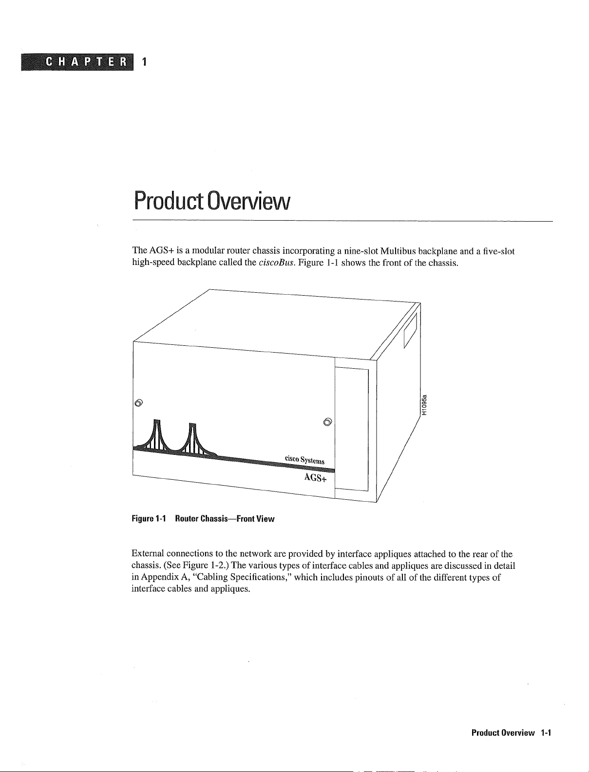
The
AGS
is
high-speed backplane
Overview
modular
called the
router chassis
ciscoBus
incorporating
Figure
nine-slot
1-1
shows
Multibus
the
front
backplane
of
the
chassis
and
five-slot
Figure
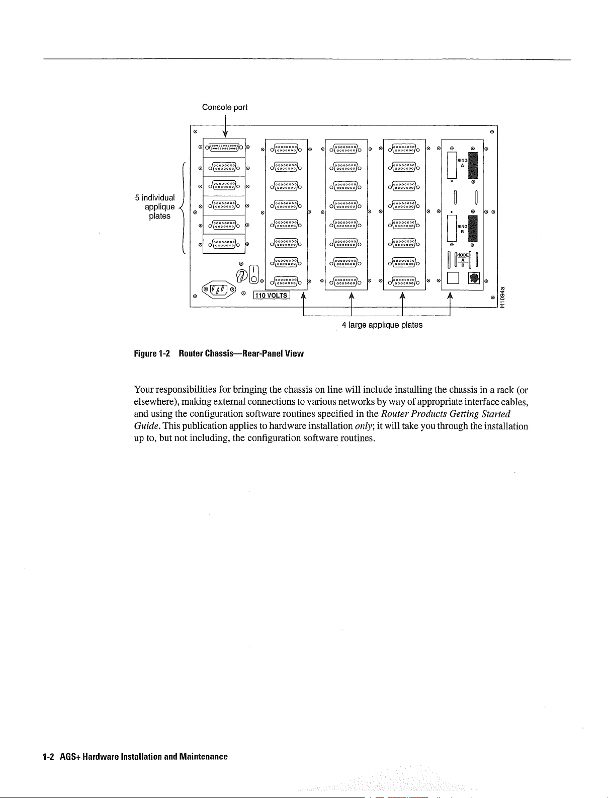
External
chassis
in
Appendix
interface
1-1
Router
connections
See
cables
Figure
ChassisFront
1-2
Cabling
and
appliques
to
the
network
The
Specifications
View
various
are
provided
of
types
which
interface
includes
interface
by
cables
pinouts
appliques
and
appliques
of
attached
all
of
to
the rear of
are
discussed
the
different
types
the
in
detail
of
Product Overview
1-1
Page 19
Console
port
5ial
plates
Figure
Your
elsewhere
and
using
Guide
to
up
1-2
Router ChassisRear-Panel
responsibilities
making
the
configuration
This
publication applies
but not
including
__
_____
ooo
for
external
I11OVOLTSI
bringing
connections
software routines
to
the
configuration
oo
oo oco
oo
oo
oo oço
oOO
large applique plates
View
the
chassis
hardware
on
line
to
various
specified
installation
software routines
will
networks
in
only
include
the
by
Router
it
installing
way
will
take
of
Products
the chassis
appropriate
you
through
ii
Getting
RING
RING
interface
the
in
Started
installation
rack
or
cables
AGS
Hardware
1-2
Installation
and
Maintenance
Page 20
Chassis
Specifications
Chassüs
Specifications
This section
Table
Table
Description
Multibus
ciscoBus
Dimensions
Weight
Power
Input
Frequency
Current
Current
Co1ing
Blower
Rear
Additional
1-1
11
dissipation
voltage
rating
and
noise
panel
If
ciscoBus
Btu
British
VAC
cfm
Cubic
dBa
Decibels
The number
lists
Chassis
backplane
backplane
DC
connector
hardware
interface
Volts
discusses
the
voltages
theimal
alternating
feet
of
availabte
general
Physical
maximum
cards
units
minute
per
A-weighted
areas
the
available
are
current
individual
specifications
specifications
Power
used
of the
for
and
Cooling Specifications
Specifications
slots
due
slots or less
slots
one
10
175 20
56
lb
2545 kg
750W
2550
U.S
110or240
U.K
220240
4763
Hz
U.S 7A
U.K
4A
U.S 55A 5V
6A@-5V
U.K
60A
6A
-12V
160
large plates
rack-mount
the
ciscoBus
is
reduced
cfm4
One
63 dBa5
19
then
plates
components
the
to
are available1
is
Btu2/hr
nominally
110
230
5V
6A
and
controller
by
used
blower
router
CSC-ENVM
the
by
25.4
VAC3
VAC
230
60
3A
VAC
VAC
1OA
1OA
-5V
individual
kit
card
if
an
auxiliary
CSC-CCTL
cmx
standard
VAC
Hz
12V
12V
will
and
and
in
port
4445
240
reduce
processor
nominal
the
plates6
power
U.S
VAC
is
used
cmx
or
this
supply
card
CSC-CCTL2
508
and 50
number
used
requirements
cm
Hz
by
in
at
in
the
least
the chassis
card
U.K
Processor
Controfler
This
used
The
Memory
section
provides
in
chassis
the
Processor cards
ciscoBus
Memory
Network
combination
controller
interface
of
an
cards
cards
network
and
overview
interface
nterf
of the
cards
ace
following
Cards
four
in
chassis
types
determines
of
printed
its
circuit
operation
cards
that
be
can
Product Overview
1-3
Page 21
Processor
Controller
Memory
and
Interface
Cards
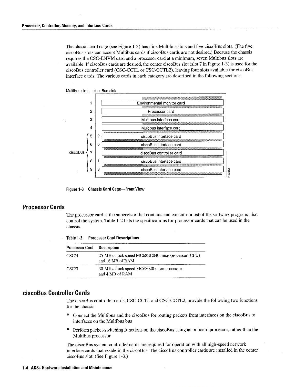
The
ciscoBus
requires
available
ciscoBus
interface
Multibus
ciscoBus
chassis
card
slots
the
CSC-ENVM
If
ciscoBus cards
controller
cards
ciscoBus
slots
cage
can
The
.-
accept
card
various
see
Figure
Multibus
card
are
CSC-CCTL
slots
has
1-3
cardsifciscoBus cards
and
processor
in
each
Environmental
the
or
Multibus
Multibus
ciscoBus
ciscoBus
ciscoBus
ciscoBus
ciscoBus
desired
cards
nine Multibus
card
center
ciscoBus
CSC-CCTL2
category
Processorcard
interface
interface
interface
interface
controller
interface
interface
at
minimum
leaving
described
are
monitor card
card
card
card
card
card
card
card
slots
is
the
The
chassis
are
used
ciscoBus
five
the
for
and
five
ciscoBus
not
are
desired
seven
slot
in
slot
four
Figure
slots
in
the
following
Because
Multibus
available
..
..........
slots
slots
1-3
for
sections
.1
.0
CJ
Processor Cards
cscoBus
Controller
1-3
processor
1-2
Chassis Card
the
system
Processor Card
card
is
Table
Description
Figure
The
control
chassis
Table
Processor Card
CSC/4 25-MHz
and
CSC/3
30-MHz
and
Cards
The
for
The
interface
ciscoBus
ciscoBus
the chassis
Connect
interfaces
Perform
Multibus
ciscoBus
the
packet-switching
processor
cards
slot
controller
Multibus
on
system
that
See
the
reside
Figure
the
16MB
MB
Multibus
controller
CageFront
supervisor
1-2
Descriptions
clock
of
clock
of
RAM
cards
and
in
1-3
lists
speed
RAIVI
speed
CSC-CCTL
the
bus
functions
cards
the
ciscoBus
View
that
the
specifications
MC68ECO4O
MC68020
ciscoBus
on
are
contains
for
the
required
The
microprocessor
microprocessor
and
CSC-CCTL2
routing
ciscoBus
ciscoBus
and
of
the
for
executes
processor
most
cards
software
that
can
be
programs
used
that
in
the
CPU
the
cards
all
following
processor
high-speed
are
provide
using
controller
from interfaces
onboard
an
with
packets
for
operation
installed
two
functions
the
ciscoBus
on
rather
than
to
the
network
in
the center
AGS
1-4
Hardware
Installation
and
Maintenance
Page 22
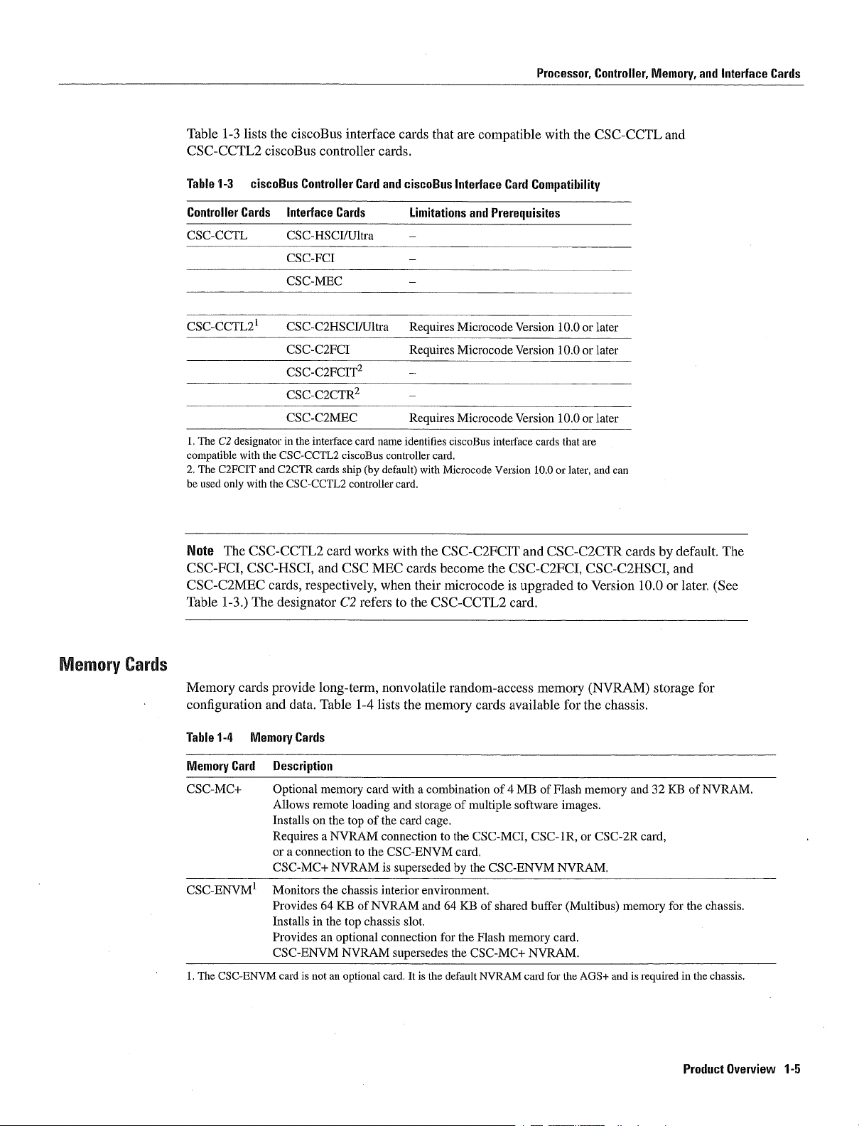
Table
1-3
CSC-CCTL2
Table
1-3
lists
ciscoBus
the
ciscoBus
ciscoBus
Controller
controller
interface
Card
cards
and
cards
ciscoBus
and
and
Interface
Cards
Processor
that
are
compatible
Interface
Card
with
Compatibility
the
Controller
CSC-CCTL
Memory
Controller
Cards
CSC-CCTL
CSC-CCTL2
The
G2
designator
with
the
compatible
The C2FCIT
be used
Note
only
The
CSC-CCTL2
and
C2CTR
with
the
CSC-CCTL2
CSC-FCI CSC-HSCI
CSC-C2MEC
Table
1-3
The
cards
designator
Interface
CSC-HSCJJU1tra
CSC-FCI
CSC-MEC
CSC-C2HSCI/Ultra
CSC-C2FCI
CSC-C2FCIT2
CSC-C2CTR2
CSC-C2MEC
in
the
interface
cards
CSC-CCTL2
card
and
respectively
Cards
ciscoBus
ship
CSC
C2
card
by
controller
works
refers to
name
controller
default
MEC
when
Limitations
Requires
Requires
Requires
identifies
card
with the
cards
their
the
ciscoBus
card
with
Microcode
CSC-C2FCIT
become
microcode
CSC-CCTL2
and
Microcode
Microcode
Microcode
Prerequisites
Version
Version
Version 10.0orlater
interface
Version 10.0
the
CSC-C2FCI CSC-C2HSCI
is
cards
and
upgraded
10.0orlater
10.0
or
that
are
or
later
CSC-C2CTR
to
Version
card
later
and
can
cards
default
by
The
and
10.0
later
or
See
Memory
Cards
Memory
configuration
Table
1-4
Memory
Card
CSC-MC
CSC-ENVM
The
CSC-ENVM
cards
and
Memory
provide
data Table
Cards
Description
Optional
Allows
Installs
Requires
connection
or
CSC-MC
Monitors
Provides
Installs in
Provides
CSC-ENVM
cardisnot
long-term
memoty
remote
the
on
NVRAM
NYRAM
the chassis
64
the
an
an
1-4
loading
top
to
KB
of
top
optional
NVRAM
optional
nonvolatile
lists
card
of
the card
connection
the
is
interior
NVRAM
chassis
connection
card
CSC-ENVM
the
memory
with
combination
and
storage
cage
to
superseded by
environment
and 64
slot
for
supersedes
It
is
the
random-access
cards
of
multiple
the
CSC-MCI
card
the
KB
the Flash
the
CSC-MC
default
available
of
CSC-ENVM
of
shared
memory
NVRAM
MB
software
CSC-1R
buffer
NVRAM
card
memory
of
Flash
images
NVRAM
card
for
for
or
Multibus
the
AGS
NYRAM
the chassis
memory
CSC-2R
memory
and
and 32
card
is
required
storage
KB
for
for
of
the chassis
in
the
Product
NVRAM
chassis
Overview
1-5
Page 23

Processor
Controller
Memory
and
Interface
Cards
Network
Interface
Cards
Network
network
CSC-MEC
With
CSC-CCTL2
Table
Cards
CSC-C2CTR
CSC-FCI
CSC-C2FCI
CSC-C2FCIT FDDI
CSC-HSCI
CSC-C2HSCI
CSC-MEC
CSC-C2MEC
CSC-C2MEC
designator
CSC-C2CTR
interface
interface
the
CSC-C2FCI CSC-C2FCIT CSC-C2HSCI
and
cards
CSC-HSCI
ciscoBus
1-5
CiscoBus
Description
2- or
4- or
or
FDDI
Provides
Port
Provides
Port
or
Complies
Provides transmission
or
or or
Provides
The
CSC-FCI
CSC-HSCI
cards respectively
indicates that
and
CSC-C2FCIT
cards
connect
and
controller
Network
4-port
16-Mbps
communications
up
connect
can
communications
upto100-Mbps
connect
can
HSSI
communications
with
upto125-Mbps
6-port
transmission rates
and
these cards
cards
your
Table
interface
Interface
ciscoBus
rate
to
100-Mbps
to
to
the
high-speed
CSC MEC
when
their
are
compatible
are shipped
chassis
1-6
lists
cards
card
is
Cards
Token
for
each
interface
single-mode
interface
single-mode
EIAITJA-613
rates
duplex
cards
microcode
the Multibus
required
port
transmission
transmission
interface
of
with
Ethernet
of
become
with
by
to
one
the
CSC-CCTL
card
Ring
is
user-selectable
card
multimode
or
with
multimode
or
card
electrical
upto52-Mbps
the
UltraNet
interface
to
up
the
is
upgraded
the
CSC-CCTL2
default
or
rates
translational
rates
with
10
Mbps
CSC-C2FCI
with
and
more networks
network
ciscoBus
CSC-C2MEC
by
fiber
bridging
fiber
HSSI
port
specification
duplex
interface
card
on each
CSC-C2HSCI
to
Version 10.0
ciscoBus
Microcode
Version 10.0
interface
way
with
port
or
controller
controller
of
capability
HSSI
later
Table
interface
software
cards
interface
and
The C2
or
lists
the
the
is
ciscoBus
CSC-FCI
required
the
1-5
With
card
cards
card
The
later
Table
1-6
Multibus
Cards
CSC-1R
CSC-2R
CSC-MCI
CSC-R16M
CSC-SCI
DCE
Data communications
1-6
AGS
Hardware
Installation
and
Maintenance
Network
Description
Single-port
4-
or
16-Mbps
Dual-port
4-
or
16-Mbps
Ethernet
Transmission
Serial
Single-port
4- or
16-Mbps
synchronous
Transmission
Ports
can
Interface
Token
rate
version
rate
and
rates
ports configurable
Token
rateisuser-selectable
serial
rates
be
configured
equipment
Cards
Ring
is
user-selectable
of
the
for
synchronous
to
up
Ring
interface
to
up
DTE
interface
CSC-1R
each
as
interface
as
port
Mbps
DCE
Mbps
DCE
Data
serial
ports
card
Token
is
user
for serial
or
card
for
or
DTE
terminal
by
interface
DTE1
by
each
way
Ring
selectable
and 10
Ethernet
way
port
equipment
of
interface
ports
of
software
by
Mbps
jumper
card
of
software
way
for
Ethernet
as
Version
or
Page 24
Card
and
Port
Limitations
Card
and
Port
Limtatons
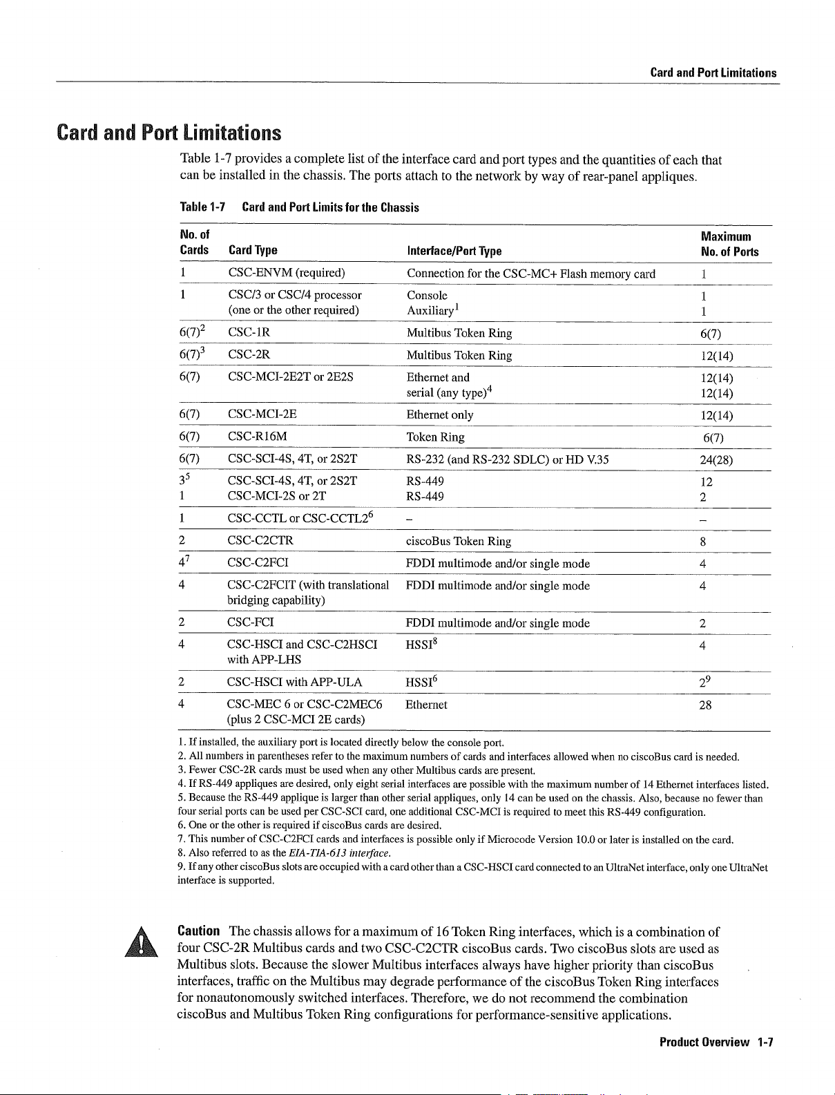
Table
1-7
be
installed
can
Table
1-1
No
of
Cards Card
672
67
67
67
67
67
35
CSC-C2CTR
47
four
interface
CSC-C2FCI
CSC-C2FCIT
bridging
CSC-FCI
CSC-HSCI
with
CSC-HSCI
CSC-MEC
plus
If
installed
All
numbers
Fewer CSC-2R
If
RS-449
Because
serial
ports
One
or
the
This
numberofCSC-C2FCI
Also
referred
If
other
any
is
provides
in
the chassis
Card
and
Port
Type
CSC-ENVM
CSCI3orCSC/4
or
the other
one
CSC-1R
CSC-2R
CSC-MCI-2E2T
CSC-MCI-2E
CSC-R16M
CSC-SCI-4S
CSC-SCI-4S
CSC-MCI-2S
CSC-CCTL
the
in
appliques
the
RS-449
other
ciscoBus
supported
capability
APP-LHS
CS
auxiliary
parentheses
cards
can be used
is
required
to
the
as
or
and
with
C-MCI
must be used
are
applique
EIA-TIA-63
slots
complete
list
The
Limits
for
required
processor
required
2E2S
or
or
2S2T
4T
or
2S2T
4T
or
2T
CSC-CCTL26
translational
with
CSC-C2HSCI
APP-ULA
or
CSC-C2MEC6
2E
cards
is
located
port
refer to
the
when
desired only eight
is
larger
CSC-SCI
per
if
ciscoBus
cards
and
inteiface
are
occupied
of
the
interface
attach
ports
the
Chassis
Interface/Port
Connection
Console
Auxiliary1
Multibus
Multibus
Ethernet
serial
Ethernet
Token
RS-232
RS-449 12
RS-449
ciscoBus
FDDI
FDDI
FDDI
HSSI8
HSSI6
Ethernet
below
directly
maximum
any
serial
than other
card
cards are desired
interfaces
with card other than
the
numbers
other Multibus cards
interfaces
serial
additional
one
is
possible only
card
and
port types
to
the
network
Type
for
the
CSC-MC
Token
Ring
Token
Ring
and
any
type4
only
Ring
RS-232
and
Token
multimode
multimode
multimode
console
of
cards
are possible
appliques only14can
CSC-MCI
CSC-HSCI
if
Ring
port
and
are
Microcode
and/or
and/or
and/or
interfaces
present
with
is
SDLC
required
card
by
way
single
single
single
the
maximum
be used
Version 10.0
connected
and
the
of
rear-panel appliques
Flash
memory
HD
V.35
or
mode
mode
mode
allowed
when
number
the
on
to
meet
this
or
to
an
quantities
iso
of
chassis
RS-449
laterisinstalled
UltraNet
card
ciscoBus
Also
of
14
Ethernet
configuration
interface
each
card
is
interfaces
because no
on
the card
only
that
Maximum
No
67
1214
1214
1214
1214
67
2428
28
needed
fewer than
one
of
Ports
listed
UltraNet
Caution
four
CSC-2R
Multibus
interfaces
for
nonautonomously
ciscoBus
The
chassis allows
Multibus
slots
traffic
and
Multibus
Because
on
cards
the
the Multibus
switched
Token
for
maximum
and
two
CSC-C2CTR
slower Multibus
may
interfaces
Ring
configurations
of
16
Token
ciscoBus cards
interfaces
degrade performance
Therefore
for
which
ciscoBus
priority
Token
the
is
combination
we
Ring
always
do
interfaces
of
not
Two
have
the
ciscoBus
recommend
higher
performance-sensitive applications
combination
slots
are
than ciscoBus
interfaces
Ring
Product Overview
used
of
as
1-1
Page 25
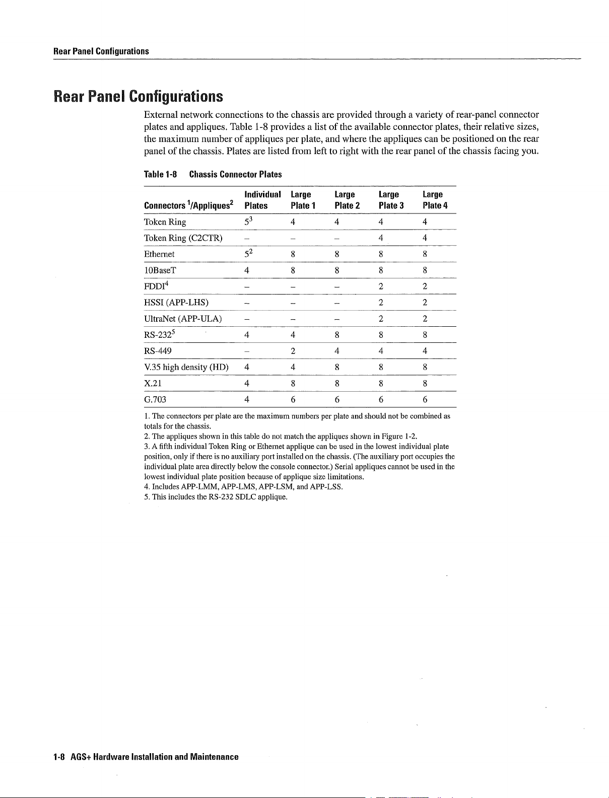
Rear
Panel
Configurations
Rear
Pane
Configuatons
External
and
plates
the
maximum
of the chassis Plates are
panel
Table
1-8
Connectors
TokenRing
Token
Ring
Ethernet
lOBaseT
FDDI4
HSSI
APP-LHS
UltraNet
RS-2325
RS-449
V.35
X.21
G703
totals
position
individual
lowest
high
The
connectors
for
the
The
appliques
fifth
individual
only
individual
Includes
This includes
APP-ULA
plate
network
connections
appliques
number
Chassis Connector
1/Appliques2
C2CTR
density
HD
per
plate
chassis
shown
Token
if
there
is
area
directly
plate
APP-LMM
the
RS-232
to
the chassis are
Table
1-8
provides
of
appliques
listed
Plates
Individual
Plates Plate Plate Plate Plate
53
are the
maximum
in this
table
do
Ethernet
Ring
or
no
auxiliary
port
below
the console
because
position
APP-LMS APP-LSM
SDLC
applique
plate
per
from
Large
numbers
not
match
the
applique
installed
on
connector
of
applique
and
list
and
left
per
appliques
can
the
chassis
size
APP-LSS
of
to
be used
limitations
provided through
the
available
where
the
with
right
Large Large
and
plate
should not
shown
in
the
The
Serial
auxiliary
appliques
appliques
the
in
Figure
lowest
cannot be used
connector
rear
be
1-2
individual
port
variety
panel
Large
combined
occupies
can
plates
of
plate
in
be
of
the
as
the
the
rear-panel
their
positioned
chassis
relative
connector
on
facing
sizes
the
rear
you
1-8
AGS
Hardware
Installation
and
Maintenance
Page 26

Chassis
Power
Budget
Chassis
Power
Budget
If
future
your
components
therefore
300W
One
One
One CSC-CCTL2
Two
One
14
Power
Available
Add
New
These
300W
Table
Card/Applique
CSC/4
CSC/3
CSC-ENVM
CSC-MC
CSC-MCI
CSC-SCI
CSC-R16M
CSC-lRand-2R
CSC-CCTL2
CSC-C2FCIT
CSC-CSFCI
CSC-C2MECx2
CSC-CSHSCI
CSC-C2CTR-2
CSC-C2CTR-4
CSC-CCTL
CSC-FCI
CSC-MECx2
CSC-HSCI
Up
Each
Up
Each
the
Following
CSC-ENVM
CSC/4
processor
CSC-C2MEC6
CSC-MCI
Ethernet transceivers
requirement
power
CSC-C2FCIT
two
cards
within
two
new
Table
1-9
Power
with
with
with
to
maximum
transceiver
maximum
to
transceiver
configuration
based
total
is
card
budget
CSC-C2FCIT
lists
1-9
Requirements
Assemblies
with
applique
applique
with
with
applique
applique
of
dissipates
of
dissipates
on
power
card
card
of
power
applique
appliques
their
an
example
card
cards
present
the
transceivers
4W
transceivers
4W
dissipation
cards
budget
power
8W
24W
needs
power
system
cards
for
is
total
is
total
change
consumption
of the
calculation
can
requirements
Individual
Power
35
31
10
28
20
34
30
34
36
50
22
48
30
42
29
50
22
48
required
required
use
the
The
individual
All
values
10 10
35 35
29 29
22 44
28 28
14
300 202 98
36
72
98
be
installed
for
Components
Requirement
following
chassis
interface
56
202
72
without
the chassis
Watts
in
are
information
has
and
in
watts
exceeding
components
total
processor
to
help
power
the chassis
you
budget
cards
choose
chassis
of
300W
must
not
power budget
exceed
of
Product Overview
1-9
Page 27

Chassis
Power
Budget
1-10
AGS
Hardware
Installation
and
Maintenance
Page 28

CHAPTER
Preparing
for
Hnstallation
Safety
Before
you
chapter
Safety
Safety
Preventing
General
Site
Preventive
Installation
Tools
Network
Distance
Console
Network
Chassis
Recommendaflons
To
ensure
Keep
Keep
Do
not
caught
install
can
includes the
recommendations
with
site
requirements
environment
Checklist
and
equipment
connection
and
auxiliary
connection
components
general safety
the chassis
tools
and
loose
wear
in
the
the
chassis
following
electricity
electrostatic
site
configuration
and
interference
area
chassis
clothing jewelry including
chassis
and
Site
required
preparation
port
considerations
follow
clear
components
Fasten
preinstallation
discharge
considerations
and
these
your
you
Log
limitations
dust-free
must
guidelines
away
tie
ESD
or scarf
consider
requirements
during
from
damage
and
walk
rings
and
and
implement
after installation
areas
and
sleeves
chains
certain
prerequisites
or other items
This
that
could
get
Warning
cause
serious
Metal
burns
objects
will
heat
or
weld
can
when
up
to
connected
terminal
to
power
and
ground
This
heated
Preparing
metal
can
for
Installation
21
Page 29
Safety
Recommendations
Safety
Electrical
with
Safety
Eectricity
Guidelines
The
successful
if
this
becomes
procedures
Warning
cord
Use
Failure
electrocution
advised
doubts about
information
Following
to
that
Before
poweroff
Disconnect
Never
Do
not
Do
not
unsafe
Before
extreme
observe
you
your
on
are
beginning
assume
work
perform
installation
Before
basic
switch
all
necessary
accessing
caution
this
warning
beginning procedure
read
through
ability
how
to
proceed
guidelines
any
for
the
before
power
that
power
alone
when
action
any
of the chassis
the
following
the chassis
around
and
the
to
perform
for
procedures
room
installing
has
potentially
that
the chassis
act
entire
any
working
requiring
in
which
been
creates
should
warning
interior
accordingly
procedure
part
near
you
or
disconnected
hazardous
not
require
will
appear
turn
off
because
potentially
may
that
requires
After
contact customer
electricity
access
to
are
working
removing
from
conditions
potential
hazard
access
power
increase
access
you
the chassis
chassis
circuit
to
at
read
exist
the
to
people
the
hazardous
the
to
the
service
to
the chassis
beginning
chassis
potential
the
interior
always
chassis
procedure
representative
check
or
makes
interior
of
related
any
and
unplug
voltages are
for
shock
interior
if
you
locate the
the
equipment
however
the
present
hazard
it
is
strongly
have
for
emergency
power
or
any
In
to
Wear
Carefully
extension
addition
power
Never
Never
locations
Never
disconnected
Use
safety
caution
install
install
touch
use
source
glasses
examine
cables
the
following guidelines
and
telephone
telephone
uninsulated
at
the
when
when
your
and
is
network
installing
working
work
missing
still
connected
wiring during
jacks
telephone
under
conditions
area
for
such
possible
safety
grounds
when
working
to
telephone
an
electrical
in
wet
locations unless the
wires or terminals unless the
interface
or
modifying
telephone
wiring
that
hazards
with
storm
lines
might
or
jack
any
as
equipment
other
is
be
moist
network
specifically
telephone
hazardous
floors
that
cabling
designed
line
to
your
ungrounded
be
may
has
eyes
connected
for
been
power
wet
2-2
AGS
Hardware
Installation
and
Maintenance
Page 30
General
Site
Requirements
Preveithig
Eectrostatic
Discharge
Electrostatic
handled
can
equipment
components
Caution
chassis
Following
Step
Step
Step
Step Handling
To
power
are
Slip
To
unpainted
Use
antistatic
voltages
repair
the
ESD
discharge
result
Tpically
however
prevent
cord
the
on
safely
the
card
voltages
guidelines
an
channel
edge
surface or
defective
or
replacement
the
and
ESD
in
complete
the successful
always
ESD
must
ESD
chassis
ejectors
new
clothing
on
Damage
damage
follow
damage
be
connected
for
wrist
strap ensuring
unwanted
frame
to
in
cards
card
The
clothing
intermittent
or
preventing
surface
remove
static
must
by
wrist
attach
its
can
which
installation
ESD
but
ESD
shielding
remain
edges
still
prevention
an
to
ESD
voltages
or
the card
strap
damage
occurs
failures
of the chassis
ESD
prevent
damage
that
another
bag
in
the
only
only protects
wrist
it
makes
to
proper
Handle
insert
the card
when
ESD
procedures
strap
shock
ground
To
prevent
static
it
electronic
hazard
good
grounding
the
shielding
into
the
can
before
card
should
connect
further
the
card
impair
skin
handling
the
by
bag
chassis
from
components
electronic
not
require handling
power
contact
the
wrist
point
its
sides
damage
if
they
Avoid
ESD
are
circuitiy
any components
be
must
strap
or surface
Place
the
to
the
will
be
contact
voltages
improperly
turned
to
an
card
card
returned
between
on
the
and
any
The
off
on
an
ESD
by
for
body
GeneraH
Site
Note
For
safety
should
be
within the
Requrements
To
preclude
chassis
front
air-conditioned
air-cooling
chassis
card
be
avoided
If
the
temperature
rack
or
other electronic
or
chassis
shutdown
Note
are
observed
has
facing
While
unnecessary
ambient
in
which
is
the
The
unintended
an
you
function
inside the chassis
top
by
router
before
periodically
internal
The
environment
purposeful
shutdowns
temperature
the chassis
unit
the
CSC-ENVM
can be
range
will
device
in
installation
shutdowns
blower
chassis
be
an
installed
of
that
If
impaired
chassis
due
of the
may
is
is
directed
unventilated
check
and
is
designed
either
shutdown
to
room
mounted
card
in
and
pulls
also
the
10
the
the intake
and
air
so
wiring
are
resistance
Mohms
chassis
air
through
to
the
intake
air
drawn
be
too
is
not ventilated
thatitenters
rack
closets
maintained
should
operate
or
CSC-ENVM
due
to
blockage
into
high
of
Any
and
value
of the
be
properly
the
card
in
level
exhaust vents
fault
or
and
poor
the chassis
This condition
properly
the
air
these
conditions
rack
systems
throughout
cage
card
failure
intake
antistatic
from
dry
sensing
external
chassis
installed
left
clean
are
blocked
is
function of the
is
higher
can
occur
when
vent
can
as
long
operation
strap
and
to
right
well-ventilated
in
will
this
ventilation
than
when
the
exhaust
of
the
inhibit air
the
as
The
maintained
with
any
desirable
chassis
site
measurement
the chassis
way
shut
down
CSC-ENVM
and
can
the
wiring
of
one
or
flow
and
prerequisites
and
this
the
when
The
the
should
air
closet
chassis
the
induce
Preparing
for
Installation
2-3
Page 31

General
Site
Site
Requirements
Envkonment
The
chassis
environment
60
decibels
Table
the
environmental
Depending
minimum
sides
to
Table
2-1
2-1
lists
prevent
can
upon
amount
Chassis
be used
Because
weighted
the
the
the chassis
the
air
temperature
specifications
temperature
of
clearance
Air
Temperature
as
tabletop
large cooling
from
or
the chassis
and
voltage
and
cooling
approximately
taking
and
Voltage
rack-mounted
fan
in
the
is
intended
warning
capability
in
the
heated exhaust
Warning
chassis
to
system
for
thresholds
of
inches
and
is
somewhat
unattended
your
Fatal
in
for
site
in
an
air
of other
Thresholds
data
processing
noisy
or
computer
the
chassis
the chassis
enclosed rack
equipment
or lab
approximately
room
and
will
require
or
Table
closet
use
2-2
at least
lists
all
on
Designation
Internal
tolerance
Air
flow
5V
12V
12V
SVsupply
Table
Description
Ambient
Ambient
Ambient
Ambient
Altitude
Altitude
Vibration
Vibration
All
intake
air
at
is
3C
exhaust
supply
supply
supply
2-2
Chassis Environmental
temperature
temperature nonoperating
humidity
humidity
operating
nonoperating
operating
nonoperating
values
operating
nonoperating
of
relative
the sensor
operating
humidity
Warning
104F
Warning Message
Threshold
40C
5%
10% 15%
10% 15%
5%
Specifications
Minimum
32F
0C
40F
40C
RH
5%
5% RH
500
152
1000
304
are
RH
noncondensing
Fatal
1094F
13 64F
10%
10%
Threshold
43C
58C
Maximum
104F
185F
95%
RH
95%
RH
10000
30000
5500
5100
100500
5001000
40C
85C
3050
9144
Hz
Hz
0.5G
1G
0.1
Hz
1.5G0.2oct./min
Hz
1.5G
0.1
oct/mm
oct/mm
0.2
oct/mm
2-4
AGS
Hardware
Installation
and
Maintenance
Page 32

General
Site
Requirements
Preventive
Site
General Precautions
Configuration
The
proper
essential
ventilated
inaccessible
Read and
avoid
help
shutdowns
The
temperature
Remember
not
Never
into
Follow
can cause
Ensure
designed
flow
placement
for
successful
can cause
by
follow
future
CSC-ENVM
that electrical
be
adequate
place
the intake
ESD
immediate
that
to direct
Avoiding
of
system
system
poor
equipment placement
these
precautions
equipment
card
maximum
to
cool
chassis
prevention
the chassis
vent
side
of the
or
cooling
Shutdowns
the
chassis
operation
malfunctions
failures
monitors the
and
minimum
equipment
equipment
side
by
next
procedures
intermittent
and
cover
air
through
when
because
and
and
to
to
card
the
Equipment
and
can
planning
reduce
interior
voltages
generates
acceptable
avoid
equipment
access
the
layout
shutdowns
make
your
the
chassis
heat
the
heated exhaust
damage
panels
card
cage
of
likelihood
and
operating
failure
your
placed
system
site
environment
reports
and
to
are
an
equipment
too close
In
addition
maintenance
layout
ambient
temperatures
equipment
in
place
open
and
of
environmentally
on
occurrences
air
from
access
rack
together
chassis
equipment
and
room
Damage
and
provides
one
secure
panel
or
wiring
front
difficult
temperature
chassis
from
will
and
locations
warnings
The
closet are
inadequately
panels
caused
will
static
chassis
redirect
alone
made
this
for
be
discharge
the
will
high
may
drawn
is
air
Equipment
Racks
Install
an
open
ventilation
negative
If
necessary
The
correct
Ensure
12to15
racks
Equipment
into
the intake
the rack
installed
the chassis
rack
air
pressure
use
that
the
inches
avoid
near
If
the
only
where
system
operate
of
baffles
rackisnot
of
vertical
obstructing
the
ports
enclosed rack
possible
that
around
the
bottom
of
in
equipment
enclosed rack
an
is
too
powerful
the chassis
chassis with
inside
overly
clearance
this
space
of the
you
the
the
enclosed rack
congested
The
Open
rack
above
are using
in
and
rack door
horizontal
racks
may
leading
that
has
closed rack
redirecting
Inanenclosed
are
generate
to failures
does
not
adequate
may
the
air
or
open
assist
can
clearance
recommended
excessive heat
have
ventilation
also
away
in
an
in
rack
is
in
the chassis
ventilation
cooling
standard
prevent
from
open
ideally
but not
that
oranexhaust
cooling
the chassis intake
rack
the
chassis
separate
for
most
required
is
drawn
at
or
near
one
should
fan
by
the
enclosed
upward
the
units
fan
creating
top
be
use
vent
with
and
of
Preparing
for
Installation
2-5
Page 33

Installation
Checklist
llnstaflaflon
Task
Chassis received
Chassis
system
Chassis
components
Read
Safety
Installation
Site
Log
Site
power
Site
environmental
Required
Network
Chassis
mounted
Chassis
connected
Network
ASCII
terminal
Console
System
port
boot
unpacked
Recommendations
Checklist
established
voltages
tools
available
connection
interface
attached
set
complete
in
for
verified
specifications
rack
to
cables
9600
Checkhst
Use
track of
procedure
your
verified
copied
and
background
equipment
optional
AC
source
and
to
console
baud
Normal
all
the
records
devices
Installation
what
verified
available
data
was done
is
completed
for
Installation
section
information
connected
port
bits
LEDs
the
Checklist
router
by
Include
following
whom
See
and
copy
the
to assist
when Make
of
the
section
Site
you
checklist
Log
with
copy
installation
your
of
this
checklist
for
each
system
on
page
2-7
by
allowing
and
make
in
Site
your
youtokeep
entries
Log
along
each
as
with
Checklist
for site
by
2-1
on
page
entered
stop
lit
no
bits
parity
Date
Router
name
_______________
Router
serial
number
2-1
Figure
2-6
AGS
Hardware
Installation
and
Installation
Maintenance
________
Checklist
Page 34

Site
Log
The
Log
entries
Site
in
might
Installation
Make
Upgrades
maintenance
the
Site
Installation
Log
common
entries
Log
provides
place
include the
progressMake
the
on
and
removal/replacement
and
expansion
to reflect
of additional
historical
near
following
Installation
the
the
following
record of
chassis
copy
history
cards
where
of the
Checklist
proceduresUse
Each
all
actions relevant
anyone
Installation
each
as
time
who
procedure
procedure
performs
Checklist
the
Site
to
is
Log
is
performed
the
router
tasks
and
completed
as
has
insert
record of
system
access
on
Site
Log
the
Keep
toitSite
it
into
the
system
the
system
Site
Log
Site
Log
update
Toos
and
Equipment
Following
Removal
Configuration
Maintenance
Corrective
Intermittent
Related
Configuration
Chassis
Phillips
Flat-blade
Medium-sized
Antistatic
ESD
wrist
comments
Required
the
are
rack-mounting
screwdrivers
screwdrivers
mat
strap
or
replacement
changes
schedules
maintenance
problems
notes
tools
adjustable
or
antistatic
or
disposable
and
from
equipment
hardware
No
small
and
and
wrench
foam
of
cards
requirements
procedures
related
No
medium
if
ESD
procedures
required
rack-mount
available
kit
included with
performed
to
and
large
attach
flanges
the rack-mount
and
screws
the
chassis
shipment
kit
and
install
the chassis
Preparing
for
Installation
2-1
Page 35

Network
Connection
Preparation
Network
RS-232
Connection
Connection
When
for
your
following
Prerequisites
variety
in
all
flow-control
Ground
Transmit
Receive
Ring
Data
Clear
The
line
12V
or
open
Data
variation
setting
modular
lines
line
Preparation
up
console
sections
of
similar
and
schemes
Data
Data
Indicate
Terminal
To Send
drivers
The
Receive Data
from
will
be
your
system
terminal
signaling
fixed-configuration
output
input
input
Ready
input
are
supplied
ringing
near
7V
This
connections
output
and
but
you
schemes
scheme
with
input
causing
can
consider
must
Each
use
products
provides
bipolar
has
10000
spurious input
from
vary
number
of
these
the
name
is
sufficient to
six
signals
12
volt
ohm
1OV
to
of
cabling
RS-232
per
power
resistor to
the
communication
to
depending
factors
considerations
The
control
line
an
open
the
following
two
12V
related
output
on
most
of
them
supply
temperature
to
is
scheme
modems
signal
server
the
cabling required
described
outputs
will
that
An
and
which
and
helps
open
the
in
is
hardware
be
near
prevent
Receive
component
used
12
Distance
FDDP
Limitations
Connections
The
length
the
signal
example
distance
distances
these
however
For instance
commonly
arise
might
greater
The
following
before
distance
The
stations
Table
2-3
Transceiver
Single-mode
Multimode
of
speed
standard
and
for
used
and
than those
installation
listed in
are
FDDI
Type
your
rate
signaling
the
the
at
can
distance
limitations
Maximum
networks
and
the transmission
coaxial
limits in
You
maximum
recommended
Mbps
compensate
shown
limits
Table
Distance
Max
24
to
Up
Upto
l.2niil.9km
and
the
distance
media
cable has
these
can
distances
greater
descriptions are
usually get
maximum
without
here
however
are
for
single-mode
2-3
Both
Transmission Distances
mi
39
for
provided
eetween
kin
any
them
FDDI
problems
are
do
and
Stations
good
not
rate
you
so
as
modes
between
the
type
channel
the
results at
recommended
for
should
at
your
guidelines
multimode
V.35
If
provide
capacity
IEEE
you
get
connections
of
cable
recommended
speeds
is
understand
good
own
for
Fiber
11
depends
used
than
twisted-pair
and
megabits
results
risk
planning your
Distributed
decibels
to
transmit the
maximum
distances
second
per
the
electrical
with
dB
on
rates
network
Data
of
the
optical
type
cabling
far
Mbps
problems
and
Interface
signals
speeds
greater
distances
connections
power
of
The
signal
For
and
than
but
that
FDDI
is
2-8
AGS
Hardware
Installation
and
Maintenance
Page 36

Network
Connection
Preparation
Ethernet
Serial
Connections
Connections
The
maximum
transmission
for
voice
the
fixed
lists
the
and
hub
Table
2-4 Ethernet
Transmission
10Mbps
As
with
the lower
baud
rate
Table
2-5
Baud
Rate
2400 200 60
4800 100 30
9600 50
19200 25
38400 12
56000
distances
cable
used
transmission
spacing
IEEE
between
recommendations
VIP
Speed
lOBaseT
all
signaling
the
baud
rate
and
distance
IEEE
Standard
Distance
8.6 2.6
but
Maximum
Max
328
systems
for
Feet
for
The
may
connections
Station-to-Hub
100
the
RS-232
RS-232
Ethernet
unshielded
serial
greater
Distance
15
7.6
3.7
network
incur
problems
for
the
Transmission Distances
signals
the
signals
Transmission
Meters
twisted-pair
that
is
maximum
Distance
can
distance
Speed
segments
at
lO-Mbps
necessary
distances
travel
Table
Versus Distance
and
UTP
data
with the
between lOBaseT
limited
2-5
lists
connections
cabling
rates
distance
the
coax-type
standard
depend
used
with
UTP
cabling
connections Table
at
any
lOBaseT
station
given
relationship
on
the
does
rate
type
is
suitable
not
require
connection
Generally
between
of
2-4
Balanced
standard
Table
Baud Rate
2400 4100 1250
4800 2050 625
9600 1025 312
19200 513 156
38400 256 78
56000 102 31
Tl
The
recommended
these
problems
drivers
relationship
2-6
IEEE
Distance
50 15
distance
In
common
howeverzexceeding
allow
Standard
limits for
maximum
practice
between
Feet
RS-449
RS-449
Distance
RS-449
distances
RS-449
signals
baud
Transmission
listed
these
to travel
rate
and
Meters
in
You
supports
maximum
Table
can
distance
Speed
2-6
get
2-Mbps
greater
for
Versus Distance
which
results at
good
rates
distances
distances
RS-449
are also
is
distances
and
V.35
recommended
not
than
signals
valid
RS-232
supports
for
and
V.35
rates
Table
Mbps
Preparing
and
2-6
lists
the
X.21
are
far
without
greater
than
any
for
Installation
2-9
Page 37

Network
Connection
Considerations
tnterference Considerations
When
between
terminal
Bad
Strong
destroy
Note
in
radio
wires
are
run
for
To
the
plant
practice
predict
frequency
and
field
wiring
can
electromagnetic interference especially
the
RS-232
and
interference
the
result
remedy
significant
any
signals
in
radio interference
drivers
strong electromagnetic
on
and
RET
receivers
distance
the
wires
in
in
This
emanating
routers
an
electromagnetic
fact
as
caused
interference
has
two
from
by
implications
the
plant
lightning
you
field
may
interference
for
the construction of
wiring
or radio
need
transmitters
to
consult
can
occur
can
experts
ConsoDe
and
If
grounding
distances
each
If
effect
other
destroy
experts
Most
without
identify
and
Auxiliary
You
rate
wiring specification
auxiliary
Cabling
router
you
wires
use
data
of
high-energy
in
data
shielded
Port
must
of
9600
to
unshielded
conductors
listed in
signal
exceed
lightning
electronic
electrical
centers
pulse
and
adjust
port
Specifications
console
recommended
devices
cannot
meters
resolve
environment
Connection
the
data
is
data
twisted-pair
the
Table
strikes
phenomena
surge
and
so take
baud
bits
The
terminal
terminal
plant wiring
2-4
use
in
your
If
you
suppression
resolve
other
precautions
with
Prerequisites
rate
no
parity
console
for
or
UTP
is
high-quality twisted-pair
distances or
vicinity
can
easily
couple
have had
and
the
infrequent
special
equipment
to
attention to
special
of
the
your
port
equipment
console
to
build
and
terminal
stop
is
and
your
cables
in
your
to
unlikely
pass
The
emit radio interference
between
electromagnetic pulse
enough
problems
shielding
of
but
potentially
These
avoid these
issues of
to
match
bits
Consult
data
communications
device
DTE
auxiliary
cables
own
plant wiring
cable
buildings give
into
energy
this
sort
in
catastrophic
problems
problems
electrical
the
console
terminals
your
equipment
If
necessaly
port wiring
with
good
with
one
ground
special
caused
EMP
unshielded conductors
the
past
you
problems
cost
can
by
providing properly
suppression
surge
and
auxiliary
documentation
DCE
refer
to
scheme
required
When
consideration
may
great
Appendix
distribution
exceeding
conductor
by
lightning
want
just
deal of time
default
port
device
to
to
described
grounded
connect
to
to
consult
for this
and
of
the
for
the
or
to
baud
the
the
Network
2-10
AGS
Hardware
Connection
Your
need some
Installation
installation
To
install
detach
To
use
attachment
and
customer
connection
Consideraflons
of the
and
the terminal
IEEE
an
unit
transceiver
service
with the
and
Maintenance
needs
following
configure
802.3
MAU
cable
depend
and
or
These
representative
lOBaseT
data
the
cable
Ethernet
and
on
many
communication
router
after
attachment
an
devices
This additional
applique
you
interface
factors
the
can
need
installation
be
at
unit
purchased
including
equipment
terminal with
and
installation
your
interface
equipment
the interfaces
to
complete
an
configuration
AUI
as
additional
is
plan
you
installation
your
RS-232
cable
DTE
procedures
need
you
an
oranEthernet transceiver
equipment
not
required
connector
802.3
for
to
Contact
lOBaseT
use
are
media
You
You
complete
may
can
Page 38

To
use
modem
RS-232 RS-449
interfaces
To
attach
Link
Control
framing
minimum
the
on
CSUIDSUs
To
connect
power
operation
Warning
not
connect
may
pose
low-speed synchronous
channel
or
on
chassis
the
service
V.35 connections
or
CSU/DSU
to
HDLC
and
ones
density
market
supply
If
the
fire
number
provide
the
230
the
chassis
hazard
chassis
is
VAC
voltage
Ti
either
of
CSU/DSU
either
in
to that
unit/digital
Ti
network
synchronous
The
bits
per
V.35
AC
to
power you
autoranging
the
United
indicated
receptacle voltage
serial
term
time
is
on
or
you
serial
ones
unit
available
or
RS-449
is
or
Kingdom
the
chassis
interface
service
at
your
unit
attachments
need
Ti
CSUIDSU
data
stream
density
need
factory-configured
refers
in
data
as
additional
electrical interface to
the
proper
All
chassis include 6-foot
label
is
mismatch
installation
CSU1DSU
are
typically
into
the
to
stream
equipment
AC
different
can cause
you
to
connect
provided
that
converts
Tl
data stream
telephone system
Several
Ti
Note
the
system
receptacle
for
either
110
from
the
equipment
need
to
the
with the correct
CSUIDSU
also
at
your
VAC
electrical
power
synchronous
the
as
the
High-Level
requirement
that
site
or
outlet
damage
network
electrical
devices
most
The
240
power
voltage
Chassis
chassis
VAC
Components
Data
of
are
Ti
cord
do
and
Chassis
Components
Table
available
Table
Component
Chassis
Processor cards
ciscoBus
Interface cards
System
External connectors
Accessories
Power
Blower
Documentation
optional
2-7
2-7
supplies
lists all
as
buses
controller
memory
options
Descriptions
of
the
components
of
Chassis
Description
9-slot
Multibus
CSC/3orCSC/4
CSC-CCTL
to interface
Up
Specific
64
KB
Alternate
CSC-MC
Mounting
Chassis
Rack-mount
MAS-400
MAS-25
MAS-lO
AGS
Hardware
Started
Intern
etworking Systems System
that
are
Components
backplane
CSC-CCTL2
or
and
controller
restrictions exist
of
RAM
32
KB
Flash
plates
will
include the external connectors
kit
110
VAC
230
VAC
110
VAC
Guide
and 64
of
NVRAM
memory
with connectors
that
includes
or
power
blower
Installation
Inrernetworking
KB
MAS-400B
included with the
and
5-slot
high-speed
cards
on
the
number and
of
NVRAM
and
MB
card
and
appliques
screws
and
240
is
MAS-1OB
and
Maintenance
Technology
Error
used
Messages
supply
or
standard
of Flash
VAC
in
240
shipment
type
for
for
the interfaces
flanges
power
the
U.K
VAC
Router Products
Terms
ciscoBus
of
on
memory
attachment
for
supply
blower
and
and
cards
the
mounting
Acronyms
Command
of chassis
backplane
that
can be used
CSC-ENVM
on
the
optional
to
various
you
the chassis
Configuration
Troubleshooting
Summary
ordered
that
or
are
card
of
in
publications
19
Guide
networks
rack
Getting
types
Preparing
for
Installation
2-11
Page 39

Chassis
Components
2-12
AGS
Hardware
Installation
and
Maintenance
Page 40

CHAPTER
RackMount
HnstalHing
This
chapter
Rack-mount
General
External
Interface
Caution Before
Requirements
conditions
possible
nstaHation
Following
closet
wiring
procedure
rack-mount
install
the
This
procedure
to
screws
will
be
attached
Step
Step
Step
provides
installation
connections
connectors
Failure
damage
is
requires
flanges
rack-mount
the
Place
Attach
Using
observing
installation
installing
section
the
procedure
If
no
might
rack
to
the chassis
one
the
to
the
to
rack
provided
The
the
rack-mount
user-supplied
the
the
the
following
the chassis
in
Chapter
read
and
chassis
for
closet
or
medium-sized
screws
require
rack-mount
rack
on
site
requirements
Chassis
information
in
to
follow
these
power
supply
attaching
mounting
flat-blade
rack-mount
two
people
flanges
stable
surface
flange
rack-mount
rack
familiarize
guidelines
and
the rack-mount
is
required
screwdriver
screws
one
to
will
with the
each
to
screws
the Preventive
or
wiring closet
could
with
lead
yourself
components
kit
and
proceed
the
user-supplied
hold the chassis
first
be
attached
front
panel
side
of the chassis with the
the chassis
mount
Site
Configuration
read
the
to
installing
to
medium
and
to
facing
the
proper
unsuccessful
an
the section
slotted
and
one
the
chassis
in
General
site
the chassis
suitable
to
attach the
you
slotted
the
section
Site
and
Installation
screws
screwdriver
and
screws
rack
environmental
installation
in
and
rack-mount
then
the chassis
or wiring
in
Chapter
rack
This
provided
closet
and
or
to
Caution Chassis
not
recommended
Step
Proceed
the chassis
can
to
the section
rear
and
be
rack
mounted
Making
with
External
tops
bottoms
Connections
flush
attach external
to
with
each
other
interface
however
cables
this is
to
panel
the
Installing
Chassis
3-1
Page 41

Installation
histaHaton
The
Following
Choose
The
ventilation
in
installation
Chapter
chassis
of the
are
guidelines
suitable
can be
and
placement
When
router
location
stacked
stacking
is
for this
that
on
recommendations
greatly simplified
does
equipment
installation
not
equipment
general
other
any
if
block
the chassis intake
made
consider
no
providing
in
rack
the
Preventive
RFI
or
that
and
wiring
this
future
closet
and
exhaust vents
stacking
Site
maintenance
mounting
meets
Configuration
is
exceeds
or
requirements
required
the
section
Making
TermhiaD
Console
Externa
Connections
Port
Caution
or
exhaust vents
the
intake of
After
chassis
connectors
After
to
attach
Connectons
The
following
that
these
that
apply
Following
The
console
connection
chassis
female
uses
connector
terminals
the
of
terminal
the
of
chassis
pinout
Do
not
place
on
another
choose
you
and
connecting
located
correctly
you
external
sections discuss the basic
requirements are
to
your configuration
the
are
port
for this
rear
facing
DB-25
for
attachment
documentation
must match
If
you
for
the
console
the chassis next
the chassis
an
on
position
interface
two
types
is
used
cable
you
connector
have
port
adequate
the
the chassis
met
to
connect
is
located
and
to
to
determine
the
not
is
of
is
external
cables
terminal
labeled
DTE
default
verified
given
are
the
refer
and
blocked
location
chassis
to
the chassis
on
requires
terminal
in
to
network
rear
to
the chassis
cable
the
connections
the
Console
the
baud
the
Appendix
another
because
the
installation
and
panel
proceed
requirements
section
to
rear
panel
This
standard
device Before
baud
rate
rate
baud
rate
chassis
the
console cables
the
to
rear
Interface
available
the
terminal
of
the
data
RS-232
of
the
baud
9600
the
of
Cabling
other
or
exhaust
is
simply
section
panel
for
Connectors
on
you
chassis
communication
connecting
terminal
terminal
Specifications
of
installing
cable
data
of
piece
chassis
one
matter of
the
to
appropriate appliques
Making
the chassis
the
chassis
will
be
in
the
upper
with
the
will
you
no
bits
check
equipment
External
for
the
rear
using
left
equipment
at least
console
be
using
parity
its
documentation
will
positioning
cable
panel
The
one
be
Connections
After
external
corner
DCE
port
The baud
or
if
the
pulled
ensuring
descriptions
with
DB-25
check
stop
the
intake
in
port
male
by
and
the
your
rate
bits
The
Auxiliary
3-2
AGSi
Port
Hardware
Installation
The
port
for
bits
with
Cabling
auxiliary
is
labeled
local
no
at least
or
parity
Specifications
and
port
Auxiliaiy
remote
and
one
Maintenance
is
DB-25
an
terminal
stop
option
and
bits
female
provides
Attaching
on
or
This
connector
the
modem
port
chassis
an
uses
DTE
If
asynchronous
The
communication
male
The
pinout
device
present
DB-25
to
it
data
for
this
is
located
terminal
requirements
connector
the
auxiliary
port requires
beneath
equipment
and
requires
portisgiven
null-modem
the
console
DTE
are
9600
baud
RS-232
an
in
Appendix
cable
port
connection
This
data
cable
Page 42

Making
External
Connections
Exteruial
CabUig
GudeHnes
The
following guidelines
chassis
Make
The
different
impossible
avoid
to
the
following
Verify
Each
interface
Ethernet
four
cables
labeled
interfaces
Avoid
Crossing
It
will
Do
not defeat
Most
interface
accidentally
cables
inadvertent
Verify
Before
double-checking
Verify
When
required
distance
described
are
Connect
The
power
power
electrical
certain
to
the
possibility
the interface
serial
would
Serial
based
crossing
high-power
not
always
and
screw-type
cable
proper
applying
all
cabling
setting
for
and
the
supply
supply
power
will
connect
you
interfaces
improperly
section
Interface
unit
should
port
and
so
be
labeled Ethernet
through
how
upon
high-power
cables
be
possible
cable
strain-relief
provide
types
disconnected
disconnection use
interface
power
the
cabling
limitations
your
connections
Chapter
cord
is
at
cord
system
factory-configured
230
up
your
electromagnetic
in
power
rated
used
connect
of
forth
Serial
fasteners
cabling
to
to
label
assist
the
connecting
numbering
have
Among
the
VAC
you
colTect
with the chassis
them
Connectors
uniquely
For
example
This
the
system
cables
with
with
interface
to
avoid
systems
some
type
these
serial
on
before
system
used
before
must
you
For
example
interference
Preparing
the
proper
is
used
near
the
in
properly
interface
connecting
types
have
however
external
an
to
the
cables
on
numbered
if
four Ethernet
through
numbering
interface
assigns
interface
cables
but
this
any
starting
prevent unnecessary
applying
of
types
cables
and
consider
try
strain
of
all
the
power
when
limitations
for
Installation
receptacle
either
for
in
the
United
input
power
the external
connectors so
unique
exercise caution
interface
verify
Ethernet while
is
cables
can cause
relief
strain
To
strain-relief
you
to
label
important
prevent
to
relief
prevent
cable
your
connect
addresses
prevent
cable
within
ports
interference
are
potential
devices
system
problems
to
the
system
number
using
110
for
RS-232
signaling
VAC
of factors related
or
Kingdom
indicates the correct
to
it
whenever
240
when
to
the
configurations
each
are
six serial
maintain
also
the
slide
connections
These
VAC
All
network
wrong
type
installed
called
in
cables
fasteners
problems
provided
or
component
units
voltage
it
connecting
possible
cabling
operation
cables
will
be
physically
the
interface
of
interface
in
the
chassis
cables
would
the
correct order of
unit
addresses
interface
some
from
being
Ethernet
on
caused
damage
to
the
cabling
be
aware
considerations
include 6-foot
for
your
to
Refer
by
of the
different
your
cables
to
used
the
be
types
AUI
by
unit
Warning
indicated
that
to
After
the
manner
isolate
installing
optional
on
receptacle
specified
the
problem
voltage
the
Router Products
mismatch
chassis
Contact customer
all
of the
refer to
and
label
rear-panel
Chapter
then
can cause
is
different
Getting
notify
equipment
from
service
cables
you
Started
Troubleshooting
customer
the
representative
can
Guide
service
power
begin
publication
damage
the
representative
outlet
the
Initial
and
voltage
for
information
configuration
If
Hardware
pose
fire
hazard
do
not
of
the
chassis
Configuration
on
the
fails
connect
how
router
to
if
to
operate
Installing
the
voltage
the chassis
proceed
using
by
in
to
the
help
the
Chassis
3-3
Page 43

Interface
Connectors
llnterf
ace
Connectors
This section includes
illustrations
on
The
the
connectors
Ethernet
FDDI
FDDI
HD
HSSI
RS-232
RS-449
Token
Token
X.21
chassis
V.35
DCE
to
AUI
single-mode
multimode
chassis
chassis
DCE
DCE
Ring
Ring
identify
illustrated
network
chassis
and
and
and
and
network
MIC
connector
network
DTE
DTE
DTE
illustrations
the
FC-type
RJ-
and
connectors
network-interface
include
and
chassis
network
connector
and
SCSI-TI
connectors
connectors
connector
11
network
of the
the
for
male
MAU
page
connectors
following
connectors
and
network
and
connector
page
page
3-8
connections
chassis
female
3-6
3-6
and
connectors
chassis
and
page
used
page
connectors
chassis
network
3-6
DB-9
with
you
3-4
page
the
chassis interfaces
will
make
page
connections
connectors
connector
3-7
Use
these
to
the
rear-panel appliques
3-4
3-5
page
3-5
page
3-7
page
3-1 Ethernet
Figure
The
FC-type
and
APP-LMS
3-2
and
FODI
Maintenance
Figure
3-4
AGS
Hardware
Installation
single-mode
FDDI
Single-Mode
AUI
appliques
Network and
connectors
Network and
Chassis Connectors
shown
in
Figure
Chassis Connectors
3-2
used
with
are
the
APP-LSS
APP-LSM
Page 44

Interface
Connectors
Warning
products
product
The
appliques
Figure
The
to
male
male
connector
MIC
3-3
HD
Invisible
when
meets
connector
FODI
V.35 cable
and
HD-26
no
the Class
Multimode
DCE
connector
laser
radiation
fiber
cable
Laser
shown
in
MIC
is
available
maletofemale
while the
be
may
is
connected Avoid
Emission
3-3isused
Figure
Connector
in
four
models
The
chassis
network
emitted
Requirement
for
Network and
end
exposure
with
DTE
connector
can be
from
the
from
the
Chassis Connections
male
aperture ports
and do
not stare
CDRH
APP-LMM
to
male
male
at
or
shown
DTE
the
female
of the
into
FDDI
APP-LMS
male
topofFigure
Winchester-type
open
to
single-mode
apertures
and
female
3-4
APP-LSM
DCE
is
34-pin
FDDI
This
male
always
Oooo
ioooooo_
Ooo
3-4
HD
V.35
Figure
Chassis Connector
and Male and
Female
Network
LI
LI
Connectors
Installing
the
Chassis
3-5
Page 45

Interface
Connectors
The
which
Figure
HSSI
3-5
is
shown
cable uses
in
HSSI
Chassis
Figure
second
3-5
and Network
generation
SCSI-Il
small
Connector
computer
cJ
system
interface
SCSI-IT
connector
The RS-232
of the
RS-232
3-6
Figure
Warning
cable
to
necessary
the
ribbon
male
cable
RS-232
DCE
To
prevent
the
SDLC
to
disconnect
cable
to
DCE
is
and
damage
applique
the
connector
used
this
SDLC
for
DIE
with the
ribbon
the
Connectors
the
to
applique
is
auxiliary
RS-232
power
cable
used
for
the
if
port
SDLC
to
the chassis turned
however
console
installed
applique
turn
while
the
to
chassis
connect
Typically
the
female
chassis
the
See
internal
it
before
port
on
the
do
not
on
off
power
DTE
Figure
will
not
connecting
connector
3-6
ribbon
be
cJ
3-1
RS-449
DCE
Figure
3-6
AGS
Hardware
Installation
and
Maintenance
and DIE
Connectors
Page 46

Figure
Interface
cJ
3-8
Token
Ring
Network
RJ-11
Connector
and
Chassis
DB-9
Connector
Connectors
Figure
3-9
Token
Ring
Chassis
and Network
NIAU
Connectors
Installing
the
Chassis
3-7
Page 47

Interface
Connectors
Both
designation
ends
of the
X.21
cable
shown
in
Figure
3-10
are
female
and
labeled with
DCBorDTE
Figure
3-10
X.21
DCE
and
OTE
Connectors
3-0
AGS
Hardware
Installation
and
Maintenance
Page 48

CHAPTER
Troubeshooting
Troubeshooting
the
Your
system appears
problem
and
This
lnftia
chassis
This
discusses
chapter
Troubleshooting
Problem
Troubleshooting systems
Environmental
Running
Overvew
Tpically
the
network
as
the
source
Troubleshooting
Hardware
went
through
to
have
chapter
how
to
use
includes the
overview
solving
reporting
bootstrap diagnostic
problems
any
Use
the
information
of the
problem
Intern
extensive
problems
also
them
following
encountered
etworking Systems
starting
includes the
with
features
tests
in this
For
additional
testing
environmental
your
at installation
Configuration
and
burn-in before
the
information
use
up
reporting
chassis
startup
to
chapter
troubleshooting assistance
publication
help
isolate
will
leaving
be
problems
the
factory
in this
chapter
features of the
related
either to
andtorule
refer to
however
to
isolate
help
CSC-ENVM
the
chassis or
out the chassis
the
optional
if
your
the
card
to
Note Whether
information
Before
you
Chassis
Maintenance
of software
Type
Date
you
Brief
description
Brief
explanation
on
call
type
received
or not
how
customer
and
agreement
you
to
serial
and
the
of the
of
proceed
version
what
can
service
number
or
new
problem
locate the
in
resolving
warranty
number
chassis
steps
problem
representative
information
are
you
have
you
the
having
taken
problem
contact customer
are
you
have
the
following
isolate
to
the
TroubIeshootin
having
problem
service
information
the
representative
Initial
ready
Hardware
for
Configuration
4-1
Page 49

Troubleshooting
Overview
Probem
SoOvüig
The
subsystem
problem
Consider
Power
backplanes
Cooling
even
System
diodes
Note
Appendix
System
the
The
key
For
cards
following
to
problem
By
is
greatly simplified
the
following
systemThis
systemThe
if
the
power
cardsThis
LEDs
complete
Reading
cablesThis
and
troubleshooting
comparing
and
wiring
on
information
their
solving
supply
the
LED
appliques
in
what
subsystems
subsystem
and
blower
fails
subsystem
cards
Indicators
subsystem
system
the
the
assembly
The
and
on
and
sections
such
system
includes the
AC
switch
blower
is
the
most
appliques
reading
includes
that
connect
discuss
as
this
is
doing
power
circuit
should
assembly
difficult
canbeused
interface
all
of
these
is
to
what
breaker
come on
card
the
internal
the
chassis
subsystems
to
supply
is
to
to isolate
try
it
should
when
connected
troubleshoot
to
help
and
and
to
the Multibus
power
identify
applique
external
the
network
in
more
the
be
directly
problem
doing
is
applied
however
LED
cables
detail
the task of
and
to
failure
indicators
ciscoBus
the
the
that
to
and
AC
light-emitting
interconnect
specific
will
source
refer to
isolating
stay
on
Troubeshoothig
the
Check
Power
With
With
Does
System
and
the
following
the
AC
If
yes
If
no
suspect
the
AC
the
system
Suspect
Check
certain that
Suspect
partially
Cooing
switch
the
AC
switch
an
ENVM-induced
the
environmental
the
power
boots
items
on
input
the
AC
on and
shut
down
chassis intake
supply
and
to
does
checks
help
input
LEDs
Systems
isolate
the
out
AC
system
after
thermal-related
requirements
failure
do
blower
LEDs
being
and
source
not
the
operate
on
exhaust
light
problem
chassis
lit
the
short time
in
suspect
Chapter
vents
blower
shutdown
circuit
are
does
on
Preparing
clear
12V
breaker
not
and/or
or the
power
operate suspect
for
Installation
5V
power
cable
the
supply
blower
and
make
failure
4-2
AGS
Hardware
Installation
and
Maintenance
Page 50

Environmental
Reporting
Features
TroubUeshooting
the
Check
System
the
System
System
System
Card
Card
Cards
following
will
Check
the
Check
the
Suspect
System
System
Check
or
Check
booting
Check
Verify
Check
Check
Check
Check
boots
boots
will
the
CSC-ENVM
the
boots
the external
the
is
not
recognized
the
the
the
is
recognized
the
Check
the external interface
items
not
boot
processor
LED
the
processor
with
with
not
boot
connection
configuration
from Flash
but
console
console
card
LEDs
card-numbering
internal
and
Cabes
to
properly
card connection
indicators
particular
particular
from
card
Refer
and
baud
by
connection
on
the
but interface
interface
help
card
Flash
between
register
screen
internal
rate
the
card
system
isolate
the
or
constantly/intermittently
See
Appendix
or software
card disconnected
applique
memory
the
on
to
the section
is
frozen
console connections
in
the
the
to
backplane
and
applique
switch
ports
cables
cables
problem
to
assuming
Flash
the
terminals
See
will
for
for
the
or
cable
card
processor
Configuration
See
Chapter
not
connection
connection
reboots
backplane
and
from the
disconnected suspect
software
and
the
MCI
card
for
documentation
Appendix
initialize
the
console cable
backplane
is
preconfigured
CSC-1R CSC-2R
the correct
Register Settings
suspect
the
jumper
applique
to
in
the card
do
so
setting
Chapter
cable
or
for
Environmenta
Check
Check
limesaver In
card
is
the
lit
troubleshooting
Reportng
The
CSC-ENVM
provides
air
threshold or
settings
will
seconds
the
temperatures
an
continue
and
DCE/DTE
that
general
problem
process
environmental
and
intake
if
error
to
run
then
the
interface
Features
card
backplane-voltage
airflow
is
detected
Power
turning
jumpers
is
if
particular
be
may
BNVM
the
check
the
not
monitoring required
is
restricted
and
is
returned
the
main
on
See
not
port
applique
more
only provides
the
ENYM
Chapter
administratively
will
or
accessible
levels
or
by
turning
breaker
if
shuts
not
internal
If
switch
for
the
any
initialize
interface
nonvolatile
the
ambient
of the
down
off
down
shut
and
cabling
card
chassis This
temperature
voltages
all
functions
the
main
is
This
Troubleshooting
the
however
and
breaker
called
before
Multibus
drift
LED
card
toggling
indicator
to
checking
checks
exceeds
away
in
the chassis
switch
the
save
memory
from
waiting
the
Initial
on
time
the
butitalso
input
given range
the
The
breaker
Hardware
the
during
applique
and
factory
20
interface
exhaust
blower
to
switch
the
and
30
Configuration
4-3
Page 51

Environmental
Reporting
Features
System
Automatic
Environmenta
Warning
Reports
The
obtains
can
display
contains the
measurements
Router
Environmental
Serial
Air
system
Internal
12
-12
-5
volt
these
flow
volt
runs
the
number
volt
volt
statistics
current
ahow
appears
line
contents
of
DC
temperature
line
line
line
Router
Messages
If
measurement
is
printed
minute
If
warning
show
Following
exceeded
to
but
measurement
message
environment
an
Router
ENVIRONMENTAL WARNING
the
warnings
is
acceptable
an
exceeds
system
exceeds
appears
example
routine
from
intake
lines
environxaent
controller
is
measured
measured
measured
measured
console
for
command
that
of
this
and
Following
00225259
good
desired
given
the desired
on
of
the
margin
the
polls
the
ENVM
buffer
exhaust
firmware version
calibrated
measured
at
5.061V
at
at
at
4.915V
margins
The
test
the
console screen
at
any
message
Airflow
ENVM
at rate
with
air
is
sample
27.0C
12070V
12.034V
system
point
margins
time
to
displayed
appears
the
show
temperatures
but
has
software
are
printed
at
determine
for
voltage
of
once
and
minute
environment
shutdown
of the
output
2.2
on
5-4093
shuts
down
not
exceeded
queries
to
the
time within four-hour
any
As
noted
on
if
the
the
measurement
console
marginal
show
the
screen
user
temperature
and
command
technician
by
at
fatal
ENVM
may
screen
stores
thresholds
environment
43.0C
margins
for
at
most
query
is
when
readings
them
The
resulting
and
mpo
warning
measurements
once
every
period
the
ENVM
the
at
warning
measurement
The
in
buffer
voltage
command
four
automatic
an
system
display
message
once
hours
using
level
You
the
has
Shutdown
Messages
is
Following
measurement
an
has
example
exceeded
Router
ENVIRONMENTAL WARNING
is
Following
has
exceeded
an
an
example
acceptable
Router
ENVIRONMENTAL WARNING
and
Threshods
The
system
displays
fatal
thresholds
Router
If
The
The
The
SHUTDOWN
test
last
system
power
point
air
reaches
measured
software
supply
of
of
the
following type
flow
problem
the
fatal
values
is
interrupted
is
shut
message
an
acceptable
message
margin
threshold
from
off
Internal
after
volt
each
displayed
displayed
and
margin
temperature
the
testpoint
of
the
of
and
few
message
the
milliseconds
the
on
and
the
on
voltage reading
measured
if
voltage
ENYM
performs
six
test
points
shutdown
console
the
measured
console
message
of
screen
temperature
screen
is
given
or
as
are
delay
5.310V
temperature
follows
saved
is
displayed
when
41.3C
when
to internal
reading
an
ambient
is
voltage
exceeds
on
given
measurement
maximum
NVRAM
the
console
temperature
or
screen
4-4
AGS
Hardware
Installation
and
Maintenance
Page 52

Environmental
Reporting
Features
Temperature
and
Caution
The
3C
and
problem
may
Airflow
Consider
Step
Step
Step
The
internal
The
system
the
power
toggling
be
indicated
Troubleshooting
the
Chassis
No
No
Blower
Last
problem
is
LEDs
processing
is
message
Determine
temperature
For
the
Is
the
Is
Is
there
Is
there
Is
the
Is
the
The
problem
For
Is
there
Is
there
Is
there
Are
turning
running
Is
there
Is
the
The
cannot
additional assistance
chassis
temperature
cannot
switch
following
shut
lit
are
still
or
suspected
ambient
temperature
sufficient
sufficient
front
air
appropriate
suspected
insufficient
any
any
there
off
an
exhaust
appropriate
be
is
completely
of the
be
is
toggled
the switch
example-system
down
activity
running
displayed
voltage
intake
or
is
problem
if
the
error
to
go
air
room
access
vent
response
contact customer
aiiflow
blockage
blockage
multiple
some
or
air
pressure
airofthe
response
resolved
shut
down
exceeds
system
restarted
until
turned
not
may
be
Guidelines
occurring
the
console
on
message
Ifitis
Step
temperature
temperature
the
of
airflow
airflow
panel
of the chassis isolated
problems
air
in
in
units installed
all
using
problems
air
going
through
within the
of the chassis
for
the
going through
around
or
around
or
of
the
other chassis
differential
chassis
for
the
these
if
the
the external
the
internal
off
and
then
sufficient to
conditions
screen
indicates
airflow
less
than
into
the
the
chassis
rack
in
questions
service
representative
answer
the chassis
the
air
the
air
in this
between
recirculating
questions
guidelines
internal
temperature
ambient
air
temperature
if
the
on
the
bring
indicates
an
gotoStep
answer
40C
or
air
air
wiring
temperature
the
at
intake
an
all
closet
place
from
the
in
Step
the
following questions
intake
vent
exhaust
rack
vent
configuration
if
possible
the
air
intake
to
its
own
in
Step
contact customer
reaches
temperature
returns
shutdown
system
air
temperature
following questions
back
or
was
up
airflow
times
less
vent
exhaust
should
for
should
than
airofall
beyes
additional assistance
If
the
allow the chassis
and
exhaust
air
intake
port
be
If
no
service
to
due
and
problem
40C
If
answer
not
the
43C
by
approximately
an
ambient
to
larger
problem
other
correct
not
is
to
vents
and
representative
voltage
chassis
yes
continue
if
threshold
an
If
level
problem
airflow
it
is air
the
will
problem
for
To
help
command
determine
Refer
why
to
the
the section
ENVM
told
Displaying
the
system
the
to
Reason
shut
for
down
the Last
Troubleshooting
use
the
show
Environmental
the
environment
Initial
Shutdown
Hardware
last
Configuration
4-5
Page 53

System
Dispaying
Bootstrap
Diagnostics
the
Reason
If
an
test
measurements
show
for
the
ENVM-induced
to internal
points
environment
Last
Environmenta
shutdown
nonvolatile
is
stored
at
last
one
any
command
occurs
random
time
Shutdown
the
ENVM
access
These
logs
memory
measurements
the
last
NYRAM
can
measured
be
printed
Only
value
from
each
of the
six
the
last
set
of
these
six
to
the
console
using
the
System
Bootstrap
Following
Router
is
sample
show
Environmental
Serial
number
Internal
Air
flow
appears
volt
line
12
volt
-12
volt
-5
volt
line
LAST
Environmental
Internal
Air
12
-12
volt
volt
flow
volt
volt
temperature
sensor
line
line
line
line
Router
Dagnostcs
This section describes
This
chassis
operating
program
The
can
diagnostic
system
output
environment
controller
is
temperature
measured
line
measured
line
measured
measured
was
was
was
was
was
how
help
you
software
00225259
good
Shutdown
4.990V
9.900V
-11719V
4.926V
tests
of the
show
last
firmware version
measured
at
5.061V
at
at
at
was
24.0C
good
to test
for
isolate
or
for
the chassis
environment
calibrated
27.0C
12.070V
-12.034V
-4.915V
Measurements
problems
rule
out
help
on
with
hardware
initialize
last
2.2
510-93
shuts
system
problems
command
down
memory
the
processor
by
at
encountered
technician
43.0C
using
hardware
mpo
the
bootstrap
when
and
installing
boot
program
the
your
main
Caution Before
Register
customer
If
remove
you
register
an
options
4-6
AGS
Hardware
Installation
angle
you
bracket
and
section
service
can
Maintenance
proceeding
in
the
start
Chapter
representative
jumpers
Once
read
through
If
you
for
from
the
the
system
in
in
bootstrap
have
information
boot
standalone
mode
this
any
file
procedure
doubts about
on
number
bootstrap
enter
how
field
to
and
your
to
bits
mode
display
the Processor
ability
proceed
The
list
to
and
bootstrap
of available
perform
Card
of the
mode
Configuration
any
part
configuration
prompt
commands
contact
is
and
Page 54

System
Bootstrap
Diagnostics
Following
with
the
CSCI3
state
/5
IS
filename Bootload
function
Deposit
Modifiers
Following
The
command
The
command
of
memory
The
command
The
conmand
no
jumpers
filename
Protocol
of
name
The
command
Enter
Memory
Probe
is
and
are
to
TFTP
Toggle
menu
display
cache
sample
Bootload filename
Continue address
Deposit
Examine
Start
Offer
value
location with
execution
up
with
help
Initialize
Stack
trace
filename
Show
configuration
Set
break
point
step
sizes
register
most
summary
the
stack
no
argument
field
to
also include
on
of the
space
next
useful
bootstrap
trace
portion
be
the
diagnostic
may
booted
may
some
in
specify
particular
to
display
test
ID/memory
Single
Test
Examine
be
of
prints
causes
runs
with
the
boot
You
runs various
device
the
file
can
host
list
from
state
for
network
diagnostic
and
of size
commands
but
register
instruction
help
be
or
bootstrap
of the
program
on
system
boots
of the
over
with
system
for
help
start
it
into
size
do
not
option
byte
byte
swap
commands
bootstrap
reinitialize
to
hardware
the default software
configuration
the
network
second
argument
but
tests
is
tests
CSC/4
processor
card
location with modifier
with modifier
start
it
settings
long
or
short
commands
the
hardware
from
ROM
You
Trivial File
which
can
is
register
using
recommended
not
host
and
include
Transfer
the
slightly
clear
assuming
Internet
the
an
different
contents
there
argument
address
are
or
default
By
can
test
Table
4-1
tested
in this
Table
4-1 Nonvolatile
Test
CSC-ENVM
System
memory
CSC-ENVM
Nonvolatile
the
Use
for
interface
order
to
be
read
the
NYRAM
The
way
64K
64K
memory
Probe
card
look
for
from
and
memory
on
test
I/O
responses
specific
written
test
the
CSC-ENVM
is
destructive
Memory
CSC/4 and CSC/3
Start
End
Start
End
memory
regions
to
examines
Addresses
2000000
200FFFF
20B0000
2OBFFFF
space
The
See
onboard
by
to
data
in
look
test to
test starts at
The
test
the
examples
memory
supplying
NVRAM
at
address
the
uses
following
the
on
processor
The
2000000
and
CSC-MC
110
You
increments
Troubleshooting
ending
space
starting
the
mapped
probe
can
or
to
Flash
in
specify
search
and
addresses
the
the
memory
memory
main
probe
for
Initial
described
as
memory
increments
registers
Hardware
cards
cannot
You
and
that
Configuration
in
be
test
in
can
4-1
Page 55

System
Bootstrap Diagnostics
Running
the
Diagnostic
Follow
Step
Step
Caution
to
Step
Note
register
mode
cable
Step
familiarize
If
when
these
Remove
configuration
you
you
Enter
Turn
prompt
Tests
steps
Turn
Remove
Access
Before
start
can
bit is
OFF
yourself
to
ON
you
to
run
power
the
front
Procedure
proceeding
the
jumpers
the
system
press
continue
cleared
power
with
the
bootstrap diagnostics
to
the chassis
access cover
in
read
with
the
from
register
with
the
Break
normal
to
zero
to
the
an
angle
Chapter
the
configuration
the
Note
the
key
execution
chassis
bracket
section
boot
jumper
Break
on
break
Wait
and
following
the
attach
Processor
register
file
positions
disable
console
of the
is
interpreted
for
the
number
system
the
appropriate
appropriate
jumpers
before
bit
terminal
system
Card
field
jumper
software
and
to
ESD
Configuration
the
on
bits
removal
to
force the
the
display
protection
steps
processor
removed
If
system
you
the
in
system
the
Register
and
from
disconnect
is
halted
banner
section
card
of
the
the
into
message
Chassis
in
Chapter
processor
configuration
bootstrap
the
console
and
Memory/Bus
Diagnostics
To
test
tin
To
use
displayed
Caution
between
configuration
Memory/Bus
Starting
Ending
Hex
Select
Number
Message
Testing
Begin
Begin
No
memory
the
If
the
argument
errors
default
asinthe
you
nonvolatile
files in
Address
Address
Tests
of
Level
addresses
pass
pass
enter
addresses
want
diagnostic
passes
during
the
following
to
preserve
memory
NVRAM
or
variable
to run
0silence
between
test
test
passes
following
and
the
at
select
the
default
your
addresses
tests
of the
NVRAM
sample
lsummary 2normal
Oxl000
and
prompt
Memory/Bus
configuration
listed in
0x400000
10
10
tests
and
Table
11 12
11
then
press
Diagnostic
4-1
12 13
press
the
because
13
files
Return
14 15
14 15
the
Return
key
after
CSC/4
the
will
pass
pass
each
processor
following
overwrite
prompt
card
test
the
key
on
the
do
not
use
the
test
End
End
4-8
AGS
Hardware
Installation
and
Maintenance
Page 56

Note
entering
encounters
In the
preceding
number
memory
Running
problems
System
Bootstrap
all
test
address
single
it
values
of
pass
displays appropriate
this
are
in
test
hexadecimal
takes
only
error
messages
few
do
not
minutes
on
the
the
use
prefix
If
the
console screen
Ox
program
Diagnostics
when
I/O
Space Memory
Probe
To
110
test
tp
The
memory
times
required
Table
4-2
Processor Card
CSCI4
CSCI3
In
the
probe
but
will
test
All
time values
The
following
ID/memory
Starting
Ending
Probe
Probing
Region
Done
space
probe begins
Memory
test
in
larger
address
address
increment
from
Ox2lOC000
enter
to
run the
Memory
11
increasing
blocks
are
approximate
example
space
the
Test
and
minutes2
minutes
the
of
shows
probe
in
0x2000000
to
at
following
at
address
memory
Memory
the
2000000 You
tests
ProbeTest
prompt
can
limes
Memory
Test
Times Probe Increment Probe
20
seconds seconds
30
seconds seconds
valueofthe
probe
increment
to10will
memory
done
test
with
probe
increments
shorts
to
Qx21OFFFF
Ux21OCO7E
exists
with
interval
OK
and
specify
Probe
press
decrease
the
Return
key
increments Table
probe
Test
limes
Increment1
the
time
taken
for
the
of
Oxl
4-2
lists
the
10
test
The
following
ID/memory
Starting
Ending
Probe
Probing
Region
Done
example
address
address
increment
from
Ox2lOC000
shows
space probe
in
0x2000000
to
test
shorts
to
0x2lOC060
done
OX21OFFFF
exists
with
increments
probe
10
with
interval
OxlO
of
10
OK
the
Initial
Troubleshooting
Hardware
Configuration
4-9
Page 57

System
Bootstrap
Diagnostics
4-10
AGS
Hardware
Installation
and
Maintenance
Page 58

CHAPTER
Maintenance
Opening
the
This
chapter
requirements
canbeconfigured
requirements
If
any upgrades
documentation
order
This
chapter
Opening
Configuration requirements
Power
Cooling
Caution Before
Chapter
Discharge
discusses maintenance
contains information
the
supply requirements
system
Safety
Damage
Chassis
Access
cover
both
to
to
the chassis
access
change
for
requiring
called
chassis
requirements
performing
Recommendations
the
rest
over
time
different
card
configuration
interior
interior
of the chassis
use
internetworking
microcode
on
and
for
procedures
any
requires
of the chassis
this
information
will
notes
the
following
system
interface
Safety
that
components
functions This
software
or
be
shipped
card
cage
and
processor
in this
with
remove
you
and
The
its
to
adapt as
chapter
Electricity
following
components
replacement
with
cards
the
front
the
review
needed
chapter
panel
procedure
As
discusses these
are
replacement
the
and
Preventing
to
your
Certain
necessaty
following
access
includes
internetworking
cards
the
parts
sections
the
and
configuration
appropriate
or
upgrades
Electrostatic
cards
instructions
appliques
in
the
or
you
top
for
Toos
Required
The
following
Screwdriver
Phillips
ESD
wrist
tools
screwdriver
strap
are
required
Medium-sized
No
flat-blade
for
for
accessing
chassis
for
cover
the
front
chassis
panel
removal
interior
removal
Maintenance
5-1
Page 59

Opening
the
Chassis
Chassis
Access
7/
Procedure
Following
Warning
cord
because
working
Step
Step
Step
Step
Step
Step
is
the
Before
hazardous
the
near
Turn
OFF
If
the
chassis
Note where
Remove
If
will
you
appropriate
make
certain
To
access
from the
the next
To
access
securing
procedure
accessing
power
power
these cables
the chassis
need
ESD
cards
chassis
step
other
the
top
for
the
voltages
supply
to
is
rack
to
handle
protection
the chassis
in
the
See
system
cover
accessing
chassis
may
the chassis
mounted
were connected
from
the
power
card
Figure
components
See
any
and
cage
Figure
interior
exist
and
disconnect
rack
electronic
is
5-1
the
attach
loosen
in
unplug
and
OFF
If
5-1
chassis
or
you
locate
interior
turn
off
near
it
all
for
transfer
components
the
AC
the
two thumbscrews
wish
and
Set
power
the
from
external
reinstallation
it
power
to
the
power
AC
to
desktop
access cards
remove
top
cover
to
supply
power
cables
cards
cord
the
the chassis
from the
or
and
but
and
seven
and
Use
work
to
in
screws
extreme
so
prevent
remove
the
No
and
unplug
chassis rear
table
forth
card
Phillips
aside
cage
attach
the
caution
shock
front
the
only
power
when
panel
hazard
panel
skip
screws
Thumbscrews
Figure
Cover screws
_-
Access
panel
5-1
Chassis
Front
and
Top
Panels
Co
Note
To
reassemble
52
AGS
Hardware
Installation
and
Maintenance
the
chassis
reverse
all
steps
Page 60

Configuring
Cards
Configurüng
Card-Nlfmbering
Cards
Some
jumpers
communications
Multibus
positions
Included
and
switches
this
list
Processor
CSC-MCI
CSC-MEC
CSC-1R
CSC-R16M
Fundamentas
Most
system
shipment
These
cards
DIP
unique
installed
switches
respectively
cards
can be
that
allow
cards
in
the chassis
in this
Following
not
are
cards
and
Multibus
becomes
but
card
numbers
are
installed
switch located
card
in
the chassis
and
are
equipment
have
section
configurable
and
and
CSC-2R
interface
operational
you
number
always
CSC-SCI
may
in
configured
to
change
you
DCE
card-numbering
is
an
is
listing
through
are
what
on
cards
have
position
the
In
general
Exceptions
installed
and
to
slots
component
CSC/3
CSC-C2MEC
for
different
from
mode
switches
illustration
of
all
hardware
CSCI4
that
require
Cards
that
renumber them
markers
The
card
each
to
this
in
the
data
of
the
are
side
card
same
user
terminal
depending
each
configurable
unique
installed
the
for
numbers
of
number
are
two
applications
that
card
alterations
card
when
system
the card
the
ENVM
slots
equipment
upon
allow
and
numbers
in
you
are
should
the
your
you
tables
cards
the chassis
order
software
assigned
These
be
and
top
For
DTE
requirements
to
reconfigure
showing
in
be
and
by
switches
unique
processor
slot
example
the chassis
assigned
are
correctly
install
that
let
way
within the
and
the
the
mode
its
to
new
the
of dual
are
set
cards
second
CSC-MCI
to
data
In
addition
them
for
configurable
Cards excluded
them
before the
numbered
additional
or
know
system
in-line
that
so
of
set
which
slot
different
jumpers
package
each
all
have
from the
card has
most
slot
from
entire
before
cards
what
card has
cards
no
top
Note
numbered
If
ciscoBus
as
Card
controller
The
Card
cardisused
designation
in
is
the
chassis
reserved
Multibus interface
no
for
the
ciscoBus
controller
cards
card
can be
by
default
Maintenance
5-3
Page 61

Configuring
Cards
Processor Card
Configuration Register Settings
Contigtratou
For
both
the
cardisused
section describes the
processor
Figure
The
processor
on
pins
far
right
vertical
and
CSC/4
Regster
the
CSC/3
and
cards
as
Both
CSC/4
configuration
settings
cards
for this
contain
processor
register
register
the
same
cards
for
the
processor
Figure
components
gurationOonsole
register
5-2
CSC/3
the
vertical
jumper
50-pin
aiid
cards
header
pair
Figure
CSC/4
have
of
pins
5-3
Processor
16-bit
in
the
shows
CardsPartial
hardware
of the
center
To
bit
set
to insert vertical
the
configuration
configuration
card
Component-Side
Refer
50-pin
5-2
register
functions
shows
connector
header
and
register
to
with the
Figure
jumper
in
and
partial
basic
View
the
the
center of
diagnostics
component-side
physical layout
far
right
Bit
5-3
To
clear
factory
settings
the
front
The
following
view
illustrated
as
16
or
bit
pairs
position
to
for
of
remove
the
edge
of
jumper
is
CSC/3
of
the
the
the
Figure
To
change
removing
and
then
the
backplane
Note
Note
5-3
CSC/3
configuration
jumpers
give
Configuration
15
14 13
Positions
and
the
privileged
ortoturn
12
1110
and shown
CSC/4
Configuration Register
register
and
restart
off
register setting
settings
the
command
the
power
system
as
reload
to
changes
factory
turn
or
change
defaults
off
change
It
take
the
is
jumper
effect
Positions
Pattern 0-0-0-1
Pattern
0-0-1-0
ROM-monitor
file
boot
jumper
jumper
necessary
setting
only
setorclear the
settings
to
after
system
the
not
remove
the
and
while the
system
bits
ROM-boot
configuration
bits
the
restarts
by
power
processor
jumper
inserting
is
card
or
still
on
from
5-4
AGS
Hardware
Installation
and
Maintenance
Page 62

The
The
operating
you
software
default
through
The
filename
and
processor
Table
lowest four
boot
field
system manually
the
set
If
boot
is
system
the
the
processor
The
5-1 Default
boot
you
filenames
used
creates
system
bits
specifies
field
set the
list
when
type
is
Boot
of the
boot
starts
the
processor
number
by
value
to
boot
when
using
filename
with cisco
name
same
FilenamesBoot
giving
the
field
netbooting
the
Table
for
in
to
boot
as
the
configuration
binary
factory
any
system
part
and
5-1
lists
CSC/3
Field
or
other
For
of the
links
If
you
boot
default
bit
example
flash
automatic
the octal
the default
processor
Jumpers
register
set
command
the
pattern
command
the
equivalent
boot
card
bits
boot
system
the boot
jumper
configuration
field
to
the
configuration
with
filenames
however
boots
value
system
system
the
of
the
and
form the
to
you
bootstrap
the default
using
commands
of 0-0-1-0
Flash
memory
processes
boot
actions
or
csc3issubstituted
To
field
for
boot
must
program
RUM
override the
card
form the
number
the
boot
bits
CSC/4
for
Configuring
field
the
boot
dash
csc4
Cards
If
Action/Filename
bootstrap
RUM
software
cisco2-csc4
cisco3-csc4
cisco4-csc4
cisco5-csc4
cisco6-csc4
cisco7-csc4
ciscol0-csc4
ciscoll-csc4
ciscol2-csc4
ciscol3-csc4
ciscol4-csc4
ciscol5-csc4
ciscol6-csc4
ciscol7-csc4
mode
Bit Bit Bit Bit
bt17YVY111J
kvv
f1SfJ\
OUb
9/
02
Note
and
must
Bit in
default
to
interpret
operation
Bit in
netbooting
loaded
completing
The
into
the
causes
the
four
be
left
configuration
Break
configuration
If
the
the
bits
cleared
the
processor
as
this bit is
system
netbooting
after
command
over
the
boot
field
bits
to
the
process
to
ignore
network
controls the
the
force
to
controls the
secondary
console
the
bootstrap
This
register
register
set
console
system
use
bootstrap
Break
of
and
into
Break
key
secondary
with
image
in
Clearing
the
bootstrap
the filename
the
key
configuration
Setting
bootstrap
then
loads
bit
monitor
bit
to
procedure
boot-csc4
in
the
register
to
causes
suspending
desired
the
are
the
when
csc3
factory
processor
boot
unused
normal
is
first
file
Maintenance
5-5
Page 63

Configuring
Selling
Cards
Note
Bit
is
by
default not
Bit
lOin
the
configuration
bit
10
causes
the
processor
to
use
all
ones
Bit
10
interacts
broadcast address Table
values
set
in
Configuration
10
Rate
12inthe
bit
NVRAM
Address
onesones
zeroszeros
netzeros
netones
settings
configuration
for
by
Table
5-2
Bit
14
Bit
out out
out
in in
in
the
Console
Port
Bits
shows
Baud
11
in
out
and
the
present
register
to
use
5-2
shows
using
Register Settings
nethost
the
four available
with
the
controls
all
register
zeros
bit
the
ip
on
the
14
combined
broadcast
for
CSC/3
the
host
clearing
which
Broadcast
determine
baud
controls
effect
address
rates
or
portion
bit
Address
the
CSCI4
10
of
baud
The
processor
of the
the
factory default
the
network
bits
10
command
Destination
rate
factory
Internet
and 14
of
cards
broadcast address
and
subnet
This
the
console
default
is
causes
effect
9600
portions
port
the
is
baud
processor
overridden
Table
Setting
of the
5-3
General
Table
Baud
9600
4800
1200
2400
Factory
Configuration Register
Bit
13
bit
13
unsuccessful
continue
cleared
Bit
14
address
in
the
ones
or
Table
Bit
15
causes
interface
and
to
factory default
5-3
System Console
Bit
12
Bit
default
Settings
in
the
configuration
causes
the
system
attempts
attempting
to
in
the
configuration
Setting
bit
broadcast address
all
zeros
depending
5-2
for
the
combined
in
the
configuration
the
system
to
addresses
automatically
causes
11
to
14
produce
not
set
to
to
load
causes
look
to
the
Port
Baud
Rate
effect
determines
operating
boot
file
boot
file
controls
the
system
bit
the
on
setting
of
bits
controls
register
load
load
register
Clearing
register
detailed
for
them
diagnostic tracing
to
system
operate
Settings
from
from the
to
14
causes
10 and
CPU
on
the
the
software
the
network
the
network
include the
the
of
bit
10
14
the
factory diagnostic
self-check
network
modes
normally
system
from
network
system
By
using
response
read-only
Clearing
indefinitely
and
subnet
network
to
set the
factory default
messages
to
not
read
the
debug
Bit
15
is
portions
and
mode
to
also
to
boot-load
memory
bit
By
subnet
entire
bit
in
automatically
configuration
conmTtands
used
ROM
13
causes
factory
default
of
the
Internet
portions
broadcast address
14
is
cleared
the
system
files
Clearing
for
password
failure
after
the
of
prompt
system
bit
broadcast
its
to
Setting
or
NYRAM
bit
recovery
Setting
five
address
for
to
13
is
to
all
See
bit
15
15
the
5-6
AGS
Hardware
Installation
and
Maintenance
Page 64

Bits
Bits
normal
Processor
Figure
the
16
through
20
through
operation
5-4
configuration
19
23
and Cache
which
and
the
however
shows
register
bit
four
Disable
Configuring
24
are
not
currently
of
pairs
they
the
optional
on
can
mode
processor
pins
be usedtoinvoke
functions
jumper
used
toward
the
far
the
respectively
configurations represents
card
installed
in
left
Slave
the
of
the
mode
on
card
50-pin
External
any processor
cage
header
partial
Reset
card
front-edge
not
used
are
function
in
Halt
view
Cards
of
Processor Card
register
24 23 222120
/1/
Slave
Reset
5-4
Figure
EPROM
Jumpers
The CSC/3 and CSC/4
functions
be
installed
change
side
these
is
changed
and
jumpers
IIIIIIIIIIIIIIIIIIIIIHIHL1
Jumpers Jumpers
W71
W53
and
CSC/3
for
These
junpersfron
Figure
U47
U45 U46 U45 U46
CSC/4
Optional
processor
the
different
W5
ft
jumpers
5-5
U48
shows
through
sizes
are
their
of erasable
changed
default
the
W52
\--
Cache
Halt
Configuration Register Settings
cards
have
only
settings
positions
the
on
W52 W52
W51
U43
U41
System
tJ44
ft
U42 U41
ft
software
EPROMs EPROMs
connector
Bits
disable
configurable
programmable
when
unless
of
jumpers
CSC/4
11111111111111111111111111L1
W71
W51
the
card
U47
U43
System
jumpers
read-only
EPROM
are
you
W51
right
through
ft
ft
ft
software
memory
instructed
side
U48
U44
U42
that
memories
W53
control
sizes are
to
on
critical
EPROMs
changed
dosowhen
the
CSC/3
memory
that
the
software
card
Do
can
not
left
Figure
______
Console
connector
5-5
CSC/3
and
CSC/4
EPROM
Jumper
LocationsPartial
Console
connector
Component-Side
Views
Maintenance
5-7
Page 65

Configuring
Cards
EPROM
Jumper
Settings
Figure
respectively
Jumper
Areas
W53
W52
W51
Factory
some
and
5-6
Figure
Note
on
megabit
EPROMs
card
at
determine
5-6
default
All
versions of
requires
the
and
versions
CSC/3
socket
if
MB
this
Figure
EPROM
Types
Memory
for
system
of
EPROM
that
location
PAL
5-7
show
27512 27010 27020 27040 27080
512K
LI
Lit
software Version 9.0
8.3
software
Jumper
System
erasable
programmable
progammable
U55
needs
to
Settings
Software
be
the
Consult
changed
EPROM
jumper
MB MB
LI1
or
later
read-only
logic
documentation
and
LI
LI
PAL
how
llI1
Version 9.0
array
the
.1
and
to
settings
later
memories
device
change
for
the
..1
LI
.1
LI LI
some
and
EPROMs
be
changed
that
shipped
it
CSC/3
MB
.1
LI
.1
Li
versions of
with
It
on
and
Using
the
CSC/4
your
8.3
the
CSC/3
are
software
cards
shipped
2-MB
processor
to
It
It
5-7
Figure
5-8
AGS
Hardware
Installation
and
CSC/4
Maintenance
EPROM
Jumper
Settings
Page 66

Coifigurüig
the
CSCMCU
The
following
and
CSC-SCI
switch
DIP
the
card
is
located
Si
I1
W94
W93
mid
near
CSCSCII
sections discuss
cards
For
For
Si
the
bus
edge
toward
LJlHhIHIIImIIImIIIIIIIHIIIIIIIIIIIIHIIL1
NVRAM
connector
EO
both
the
MCI
connector
the
right-front
Ifl
Cards
the
various
card
cards
card
Card-numbering
Factory
jumpers
for
W62
W60
W51 W41
W50 W40
II
El Si
the
See
edge
DTE
configuration
numbers
card-numbering
Figure
of the
default
set
operation
SO
5-8
card
switch
are
changes
assigned
switch
For the
See
Si
LEDs
Figure
SCI
Configuring
that
can
be made
by
setting
is
located
Si
the
card
to
dual
in-line
toward
card-numbering
the
CSC-MCI
package
the
back
switch
Cards
of
5-9
Figure
Figure
5-8
5-9
Factory
NI4EII
N13
N13
NIl
MCI
Card
default
11 .1
S3 S2
SCI
Card
Jumpers
Jumpers
jumpers
NI8
EEl
NI7
NIB
N15 N21
and
SwitchesComponent-Side
set
for
DTE
N24fIEl
N23
N22
Si
and
SwitchesPartial
operation
EION2B
SO
N27
N26
N25
Component-Side
View
I----
EIEIEiDI
LEDs
Card-numbering
switch
Si
View
Maintenance
5-9
Page 67

Configuring
Cards
CSC-MCI
and
CSC-SCI
Card
Numbering
Table
5-4
shows
numbers
within the
numbers must
ciscoBus
Table
Card
01
Use
The
default
5-4
No
only
ciscoBus
controller
if
the switch
also
CSC-MCI
Si-i
0ff
Off Off
Off Off
Off Off
Off
Off
Off
Off
ciscoBus
no
controller
Si
settings
set
of
MCI
and
SCI
be
unique
among
card
is
installed
and CSC-SCI
S1-2
Off Off
Switch
S1-3
Off
On
On On
On
On
On On
On On On
cardiscard
controller
Off
Off
cardisinstalled
number
Si-4
Off
On
Off
Off
On
Off
and
SCI
cards
The
for
card
numbering
cards
installed
the
other
cards
installed
the
ciscoBus
Si
by
Settings
controller
for
in
Card
the
the chassis
Card number
cardiscard
Numbering
MCI
must
be
number
unique
can
be used
card
These
card
if
only
no
default
by
CSC-MCI
and
CSC-SCI
On
Mode
the
MCI
equipment
through
configure
interface
applique
Following
must
Router
Enter
Edit
with
interface
clockrate
AZ
Router
Router
The no
desired
these
The
recommended
V.35
clockrate
Refer
commands
entered
1200
1000000 1300000 2000000
and
with the clockrate
2400 4800 9600
fastest
SDLC
and
Clocking Options
card
jumpers
mode
DCE
in
DCE
the
clock
subcommand
be
DCE
is
sample
configure
configuration
DELETE
serial
64000
write
command
to
the
Following
speeds
for
appliques only
W5
and
On
the
SCI
mode
In addition
each
configured
of
the
serial
speed
rate
on
where
or
output
terminal
commands
CRTL/W
memory
removes
appropriate configuration
are the
speed
19200 38400
and 4000000
not
or
at
work
RS-232
speeds
might
RS-232
W4
control the
card
jumpers
to
changing
interface of the
is
the
as
DCE
clockrate
one
and
CRTL/U
the
clock
acceptable
command
56000 6400 7200
cable
if
your
SDLC
to
64kbps
up
bit
per
N22 N26 N12
these
rate
of
to
generate
command
speed
line
rate
and
reference
clockrate
is
too
signaling
for
serial
ports
jumpers
interface
the
interface
the
with
CTRL/Z
if
data
terminal
speed
card
clock
publication
settings
and
and
for
in bits
equipment
N16
DCE
using
signals
appearing
in
per
for
data
control
operation
the
second
more
communications
the
clockrate
DTE
information
as
you
mode
they
serial
ports
must
speed
The
is
on
are
12500 148000 500000 800000
faster
than
long
It
speeds
Speeds
is
recommended
above
148
kbps
that
this
use
you
RS-449
use
the
X.21
are
not
RS-232
or
HD
5-10
AGS
Hardware
Installation
and
Maintenance
Page 68

Most
an
Internal
jumper
Nil
Occasionally
transmitted
appropriate
however
Typical
second
some
Serial
so
for
the
Table
The
last
either
default
unit/digital
Table
DTE
interfaces
Transmit
areas
through
data
jumpers
an
delays
Mbps
margin
Clock
cable
5-5
and
two
DTEorDCE
setting
service
5-5
CSC-MCI
require
Clock
W40
through
N28
occur
delays
that
may
W42
inverted
for
length
columns
clock
indicate
depending
temperature cable
transmit
and
Table
5-6
of
applique
to
work
unit
Jumper
noninverted
W53
between
push
aiid
is
that
the
upon
CT
circuit
show
these
with the
CSU/DSU
Settings
Normal
and
the
the
the
data
W52
for
not
recommended
inverted
the
DTE
and
mustbeused
delays
the
jumper
tables
DTE
Unless
DTE
applique
provides
for
External Transmit
The
signal
SCI
card
Serial
Clock
transition
the
MCI
clock
may
clock-to-data
other variables
Inverting
in
the
DTE
settings
and
DCE
specifically
which
the
Clock
Options
Clock
MCI
card
clocking options
Transmit External
outtothe
and
N13 N17 N23
be
appropriate
skews
Some
the
clock
and
DCE
for
the
MCI
indicate the
all
noted
requires
clocking
for
signal
clocking options
where
point
above
and
setup
DCE
may
and
SCI
setting
products
external
the
circuit
are
devices
be
clocking
All
controlled
SCTE
using
and
required
the
clock
are
DCE
N27
1.3
only
that
shipped
interfaces
controlled
are
by
jumper
clock
and
inverted
an
for
the
SCI
megabits
will
options respectively
should
not
way
the
per
and
allowing
accept
to
compensate
be
with the
channel
used
Configuring
require
the
clock
SCTE
factory
service
Cards
by
areas
is
with
Jumper
W53
W52
W5
W50
W43
W42
W41
W40
Pair
Recommended
Signal Description
Normal
External
Inverted External
Normal
Internal
Inverted
Normal
Inverted External
Normal
Inverted
Internal
External
Internal
Internal
setting
Transmit
Transmit
Transmit
Transmit
Transmit
Transmit
Transmit
Transmit
Available but not
Clock
Clock
Clock
Clock
Clock
Clock
Clock
Clock
Interface
Serial
Serial
Serial
Serial
Serial
Serial
Serial
Serial
recommended
DIE
X1
X1
DCE
Maintenance
5-11
Page 69

Configuring
Cards
Table
5-6
CSC-SCI
Jumper
Settings
for
Clock
Options
Jumper
24
23
27
26
25
22
21
28
14
13
12
11
18
17
16
15
Pair
Recommended
Signal Description
Normal
External
Inverted External
Normal
Internal
Inverted
Normal
Inverted External
Normal
Inverted
Normal
Inverted External
Normal
Inverted
Normal
Inverted External
Normal
Inverted
Internal
External
Internal
Internal
External
Internal
Internal
External
Internal
Internal
setting
Transmit
Transmit
Transmit
Transmit
Transmit
Transmit
Transmit
Transmit
Transmit
Clock
Clock
Clock
Clock
Clock
Clock
Clock
Clock
Clock
Transmit
Transmit
Transmit
Transmit
Clock
Clock
Clock
Transmit
Transmit
Transmit
Available but not
Clock
Clock
Clock
Clock
Interface
Serial
Serial
Serial
Serial
Serial
Serial
Serial
Serial
Serial
Serial
Serial
Serial
Serial
Serial
Serial
Serial
recommended
DIE
X1
X1
DCE
CSCMCJ
Grounding
Options
The
CSC-MCI
options
specifications
signals
the
signal
pairs
Table
Jumper
W90
W91
W92
W60
W6l
W62
the
On
IEEE
the
second
card
orientation
Version
to
which
5-7
Pair
MCI
802.3
to
accommodate
be
grounded
and
is
CSC-MCI
card jumpers
electrical
Ethernet
card
provides
Ethernet
removing
compatible
Jumper
Signal Description
Receive
Transmit
Power
Power
Transmit
Receive
Pair
Pair
Paii
Pair
Pair
Pair
levels
port
shown
Version
Table
Shield
Shield
in
the
jumper
with
Settings
Shield
Shield
Shield
Shield
W94
The
Figure
to
up
differences
5-7
both
and
Jumper
factory
Ethernet
two
between
permits
lists
the
allows the
Ethernet
for
Grounding Options
Interface
First
First
First
Second
Second
Second
W93
W94
default
5-8
place
certain
CS
C-MCI
signal
and
Ethernet
Ethernet
Ethernet
Ethernet
Ethernet
Ethernet
are
3-pin
controls the
is
to
jumper
the
SCI
ports
the Ethernet Version
to
signals
float
grounding
to
float
The
factory
IEEE
802.3
requirements
on
first
IEEE
the lower
that
Ethernet
802.3
jumpers
select
card has
whereas
options
select
Ethernet
pair
port
none
and
Inserting
default
between
of
and
pins
IEEE
IEEE
is
jumper
Version
and
to
to
8023
jumper
ground
Ethernet
select
uses
802.3
requires
W93
grounding
electrical
grounds
all
and
controls
Using
Ethernet
the
signal
the
5-12
AGS
Hardware
Installation
and
Maintenance
Page 70

Configuring
the
CSC-MEC
5-10
Figure
Ethernet Version
factoiy
Version
defaults
and
and
shows
IEEE
CSCC2MEC
the
appropriate
cables
to
5-11
Figure
802.3 cables
Cards
jumper
the Ethernet
shows
The
LEDs
the
settings
connector
appropriate
explanation
jumpers
Jumper
jumper
for
Wi
settings
settings
the Ethernet
through
shown
to
jumper
use
W6
when
to
in
settings
use
Figure
you
when
Configuring
you
5-10
are
attach Ethernet
follows
Cards
attach
Figure
Figure
Jumpers
connection
Figure
so
forth
5-10
connector
Wl
the
corresponds
facing
consecutively
Ethernet connectors
for
Ethernet
Ethernet connectors
for
Ethernet Version
through
is
moved
electrical
the
component
W6
to
Version
set
over
specifications
the
to
far
the
one
E5
CJ
cJ
E5
and
IEEE 802.3
electrical
pin
left
side
set
pin
compare
of
connector
of the
specifications
its
corresponding
card
the
E0
with
jumpers
using
the
for
the Ethernet transceiver
in
Figure
connector
the orientation
connectors
at
5-10
the
Wi
and
for
seen
bottom
and
E0
in
Figure
Each
EU
5-10
Jumper
Settings
EU
5-11
Jumper
Settings
sets
on
pin
Each
jumper
to
5-il
or
Figure
Pin
set
corresponds
change
Wi
5-11
Note
All
CSC-C2MEC
There
are
CSC-MEC
5.0
CSC-MEC
jumper
settings
differ
two hardware
cards
can be used
cards
only
cannot
for
the
firmware
by
versions of
as
CSC-MEC
version
the
CSC-MEC
CSC-C2MEC
also
apply
the
cards
to
the
CSC-C2MEC
Version 5.0
the
with
CSC-C2MEC
works
only
and
Version
appropriate
The
with
5.1
microcode
CSC-MEC
the
CSC-CCTL2
Version
but Version
5.1
Maintenance
and
5-13
Page 71

Configuring
Cards
Configuring
CSC-1R
and
the
CSC-2R
CSC1R
The
following
Card
Switches
card
on
the
listed in
are
card
and
have
Figure
The
card
allow
cards
CSC-
fundamentals
and
Numbering
numbering
CSC-1R
is
shown
the
5-12
numbers
the
system
are
installed
1R
card
CSC-2R Token
sections discuss
through
Table
same
CSC-1R
on
within the chassis
and
CSC-2R
5-8
the
CSC-2R
function
II0000000000IIuauuuuunIi00s004
and CSC-2R
of
each
to
distinguish
they
are
installed
Table
apply
Ring
the
configuration requirements
the
front
cards
left
from
card
Switches
Card-numbering
switches
Card-Numbering SwitchesFront-Edge
card
should
they
5-8
lists
of the
edge
Switches
select
to
to
when
right
numbering
LEDs
within
between
be
numbered Card
should
also
the
card-numbering
Cards
through
certain
multiple
CSC-1R
through
the desired
viewing
switches
10
type
cards
be
Card
should
and
card
the
are
Token
of
and
and
scheme
CSC-2R
have
front
in
all
one
Card
number
the
be
Ring
Card
for
no
same
type
edge
down
for
the
cards
function
View
and
For
If
one
All
the
CSC-
These
of
the card
order
off
Token
so
example
CSC-R16M
other
CSC-
see
and
Ii.i.ffil
forth
1R
and
Figure
Configure
switches
Only
position
Ring
must
card-numbering
1R
and
CSC-2R
be
if
two
card
CSC-2R
5-12
the
the
through
on
unique
CSC-
and
control
switches
CSC-IR
the
one
cards
card
to
1R
Table
Card
Switches
Down
5-8
CSC-1R and CSC-2R
No
Switch
Down2
Up
Down
Up Up
Down Down
Up
Down
through
Switch
11
havenofunction
is off
Card-Numbering
Switch Switch
Down
Down
Down Down
Up
Down
Down
Up
Down
Up
Up Up
Switch
Settings
5-14
AGS
Hardware
Installation
and
Maintenance
Page 72

Configuring
Cards
Selecting
CSC-1R
and
The
immediately
routine
The
port
sample
second
Caution
bring
ringspeed
only
CSC-2R
speed
speed
speed
Router
Enter
Edit
interface
ring-speed
interface
ring-speed
AZ
Router
Router
down
selectable
Token
of the
the
of
output
Mbps
configuration
with
Port
Ring
Token
after
the
terminal
config
the
ports
The
ports
of
how
using
configure
DELETE CRTL/W
tokenring
16
tokenring
16
write
memory
speed
the
16
ring
Oniy
speeds
The
Port
Ring
first
reboot
these cards
on
are
independent
to
configure
the
config
terminal
commands one
this line
must
equal
port
values
for
the
Speed
ports
following
command
terminal
and
ring
inserts into
of
or
CSC-
on
must
both
and
16
1R
the
CSC-1R
or the
be
and
can
ports
command
per
CRTL/U
the
preceding
speed
the
ring
Mbps
and
CSC-2R
installation
setup
configured
be
on
Failure
will
and
configured
the
line
when
be
CSC-2R
using
command
by
CSC-2R
with
line
to
match
you
accepted
ports
the
for
Token
CTRL/Z
are not
press
cards
must
be
configured
either
the
configuration
there
is
used
speed
after
card
no
speeds
for
for
to
entering
because
user
different
two
Ring
the
port
Return
the
by
system
factory
the
dialog
default
for
Following
16
megabits
the
CSC-lR
ring
speed
the
command
these
is
per
can
the
are
Maintenance
5-15
Page 73

Configuring
Configurhig
Cards
the
CSC-R16M
The
following
Token
sections discuss
Rung
Card
the
configuration requirements
of the
CSC-R16M
card
CSC-R16M
Card
Numbering
The
package
are set
to
right
unique
CSC-Rl
and
card-numbering
Component
sideofcard
Figure
Table
Card
Switches
Down
card
number
DIP
to
down
The
to
allow
6M
cards
one
CSC-1R
5-13
CSC-R16M
5-9
CSC-R16M
No
Switch
Down2
Up
Down
Up Up
Down Down
Up
Down
through
Switch
switches
card
is off
of the
CSC-R16M
on
or
oft
Figure
number
the
are
card
scheme
system
installed
of
are
installed
for
12345678
Card-Numbering
Card-Numbering
11
Switch Switch
Down Down
Down Down
Up
Down
Up
havenofunction
the
to
the
front
5-13
each
distinguish
is
edge
shows
card
should
they
they
CSC-R16M
Not
SwitchesPartial
Switch
Down
Down
Up
Up
Up
selected
of the
these switches
within
between
be
also
used
Seftings
through
card
Only
certain
type
multiple
numbered Card
should
be
All
other
card-numbering
_______
Front-Edge
the
Card
on
use
switches
the
Token
cards
of software-readable
through
card
front
and
Ring
of
one
type
and
Card
and
Card
fundamentals
View
edge
If
Table
so
For
one
are
as
forth
dualin-line
used
viewed
example
CSC-Rl
5-9
apply
lists
must
all
from
6M
the
others
be
if
left
two
card
5-16
AGS
Hardware
Installation
and
Maintenance
Page 74

Chassis
Power
Supplies
Selecting
CSC-R16M
Token
The
port
CSC-R16M
jumper
jumper
at
posts
jumper
________
J17j
J2f
..E51.Jl
Figure
5-14
Ring
speed
at
jumper
at
jumper
To
Port
for
location
install
_______I
J20
J19
CSC-R16M
Speed
of
the
çsc-R16M
either
area J22
J22
area
J21
the
J18
12345678
Card-numbering
switches
Jumper
4-megabits
selects
CSC-R16M
J22
the
jumper
______
IJJJjJ
and
factory
4-Mbps
LEDs
Switch
card
is
second
per
default
operation
cards
remove
ii
J21
________
J121I
J11J1OJ9 J6J5J4J3
Positions
jumper
are
the
ii
Mbps
setting
shipped
jumper
Port-speed
jumper
11
configurable
or
selects
The
spare
J13.
li
16-Mbps
configured
from
J22
16-Mbps
jumper
J21
Jumper
operation
J22
area
operation
to
use
to
run
at
at
configures
See
J22
is
16Mbps
Figure
while
placed
J22
5-14
installing
the
No
on
the
has
no
Chassis
Chassis
Power
CooUng
Caution
to
ring
cause
SuppDies
The
chassis
the chassis
supply
of
your
following
The
The
System
The
chassis
United
cooling
voltage
The
The
The Token
which
the
no
damage
the
uses
uses
the
problem
system
product
contact customer
by
information available
number
MAS-400
supply
power
MAS-25
chassis
uses
U.K
type
the
Kingdom
system
problem
of
your
system
product
chassis
number
type
Ring
port
cardisattached
to
the
CSC-R16M
400W
model
400W
model
checking
the
model
volts
110
power
are
you
model
MAS-lO
the
chassis
contact customer
and have
model
are using
you
alternating
supply
using
uses
speed
MAS-25
label
of
the
of the
you
Failure
card
MAS-400
service
nexttothe
the
power
240
MAS-1OB
or
MAS-
the
following
blower
set
on
to
match
MAS-400B
or
power
representative
power
supply
current
VAC
lOB
service
information available
vent
CSC-R16M
the
these
supply
blower
exclusively
representative
assembly
speeds
If
switch
need
you
power
vent assemblies
power
you
Before
on
supply
If
you
can
determine
the
you
card
must
bring
supply
calling verify
rear
or
determine
Before
need
match
down
the
In the
that
you
of the chassis
the
MAS-400B
for
system
that
calling verify
MAS-lO
the
ring
United
have
the
you
or
of
speed
but
Kingdom
power
input voltage
and have
240
cooling
have
the
the
MAS-lOB
will
VAC
In
input
the
the
the
Maintenance
5-17
Page 75

Card
Illustrations
Card
Hiustrations
Following
the
chassis
and
switches
CSC-CCTL
the
CSC-CCTL2
CSC-1R
CSC-2R
CSC/3
CSC/4
CSC-C2CTR
CSC-C2FCI
CSC-C2FCIT
FDDI
CSC-C2HSCI
CSC-C2MEC
CSC-CCTL
CSC-CCTL2
CSC-ENVM
CSC-MCI
CSC-R16M
CSC-SCI
are
Use
processor
processor
applique
illustrations
on
card
Token
Token
multiport
serial
these
the
cards
or
the
card
Ring
Ring
ciscoBus
FDDI
FDDI
cables
High-Speed
Ethernet
ciscoBus
ciscoBus2
environmental
Token
communications
illustrations
in
CSC-CCTL2
For
interface
interface
card
page
card
page
Token
interface
interface
to
controller
communications
Ring
of
all
your
more
FDDI
interface
controller
interface
of the
to
chassis
information
card
card
5-19
5-20
Ring
card
card
card
Serial
card
monitor
interface
locate software
Cards
and
card
5-18
page
5-19
page
interface
5-21
page
5-21
page
connectors
Interface
card
page
page
card
page
card
interface
card
page
interface
with the
cards
refer to
card
HSSI
5-23
page
5-25
card
processor
page
5-22
5-23
5-24
card
page
and
with the
Table
page
and
microcode
designator
5-20
5-21
card
page
5-25
1-3
page
5-24
controller
C2
EPROMs
C2
designator
in
Chapter
5-22
cards
connectors
canbeused
can
that
only
canbeused
jumpers
with
either
be
used
in
the
with
5-18
AGS
Hardware
Figure
Installation
5-15
and
CSC-1R Token
Maintenance
Card-numbering
Interface
Ring
switch
CardComponent-Side
View
Page 76

Figure
5-16
CSC-2R Token
Card-numbering
Interface
Ring
switch
CardComponent-Side
View
Card
Illustrations
Figure
LI
5-11
RAM
CSC/3
array
Processor
L_J
HUH
PAL
register
CardComponent-Side
UUUUUHHHHHHUDUHHHL
EPROM
chip
____
U55
I____
jumpers
W71I
W53j
W52j
W51j
View
U47 U48
45
U43 U44
U41 U42
software
System
EPROMs
connector
U46
Maintenance
5-19
Page 77

Card
Illustrations
______ ______
___ ___
_____ _____
____ ____
________
DRAM
array
L............J
OIIIIUIIIIIIHIIIIJIUIIUIIIIIIIIUIHIUIIIOIUIL
EPROM
jumpers
W7l__U47
W52
45
W51 U43 U44
U41
System
EPROMs
U48
U46
software
Figure
Figure
5-18
CSCI4
Processor
___ ___
u1j
LEDs
5-19
TRO TR1 TR2 TR3
CSC-C2CTR
CardComponent-Side
ciscoBus
Token
register
View
Microcode
EPROM
___ ___
lnterace
Ring
connector
CardComponent-Side
Uu
View
5-20
AGS
Hardware
Installation
and
Maintenance
Page 78

Io1
04 04 04 04 04 cJ 01
Microcode
EPROMs8
Card
Illustrations
.04
FDDIAEIM FDDIBFJN
5-20
Figure
CSC-C2FCI
FDDIAEIM FDDIBFJN
5-21
Figure
CSC-C2FCIT FOOl
FDDI
Interface
Interface
FDDICGKO FDDIDHLP
CardComponent-Side
Serial
PROM
FDDICGKO FDDIDHLP
CardComponent-Side
View
Microcode
EPROM
U32
04
View
FDDIDHLP
5-22
Figure
FOOl
P4
FDDIAElM
Applique
Cables
to
interface
FODI
card
FDDIBFJN
P3 P2
FDDI
applique
FOOl
Cables
Card
to
FDDICGKO
ConnectorsPartial
P1
04
LI
LI
Component-Side
View
Maintenance
5-21
Page 79

Card
Illustrations
JtIJIuIlHIJIIJwIIluuIIflIHhIIIIIIL_i
________ ________
_____ _____
5-23
Figure
Receive
CSC-C2HSCI
Power
connector
High-Speed
EPROMs
Transmit Control
Serial
Interface
HSSI
U708
U707
________
ff1fi11
c_
Microcode
15
LJ1LIfl
LiLHll
CardComponent-Side
U809
U808 U910
U807 U909
U806 U908
EPROMs
U911
Microcode
11
View
5-22
AGS
Hardware
Figure
Note
but with
same
Installation
5-24
The
CSC-C2MEC2
conespondingly
location
and
LEDs
EO
CSC-C2MECQ
Maintenance
Ethernet connectors
Ethernet Interface
and
CSC-C2MEC4
fewer
Ethernet
eion_
CardComponent-Side
cards
connectors
and
ES
are
identical to
LEDs
View
The
the
microcode
CSC-C2MEC6
EPROMs
card
in
the
are
Page 80

Card
Illustrations
____IuIIIIIIIIIlHhIIJIIItIIIIIIIIIIIIIII1______j
Figure
5-25
CSC-CCTL
ciscoBus
IIIIIIIIIIIIIIIIIIIIIIIJIItIIIIIIIIJlIIII
LEDs
Controller
CardComponent-Side
IIIIIIIIIIIIIIIIIIIIHhIIIIIIIIIIIIuhIIII
Microcode
EPROMs
Si
Card-numbering
9i
flc
ft3JD
U206
U205
U202
U201
U203
Iu
U208
U209
switch
View
Figure
5-26
CSC-CCTL2
ciscoBus2
LEDs
Controller
_____
IU-56
U-55
Card-numbering
CardComponent-Side
Microcode
EPROM
U-6
switch
View
Maintenance
5-23
Page 81

Card
Illustrations
Do
not
any
scneor
5-27
Figure
CSC-ENVM
cables
connect
to
L_____
Environmental
iiiIIiIiitiiIiiIIIiIHiIIiIiIIiiIiItiiIII
Firmware
EPROM
UlO
0000
J20
Monitor
000
iio
NT
U26 U27
LEDs
RFU
connector
CardComponent-Side
U25
20-pin
View
Version
jumpers
W94
W93j
NVRAM
connector
OIW6O
EO
5-28
designator
serial
CSC-MCI
CSC-MCI
one
connectors
combinations
Figure
The
connectors
two
interface
CSC-2E
Multiport
Ethernet
One
HIIIIIIIIIIIIIIIJIIIIIIIIIIIIIIIJIIIIIIIIHL
Card-numbering
U74
U73
W53na W43n6
W62
W52
W61
W51
W50
Ii
El
Communications
includes three
connector
or the other of
Si
switch
Clocking
jumpers
92
Wi
W40
different
and one
these
Interface
________
________
_________
________
SO
physical
serial
three
Bus-timing
PAL
U313
U312
U311
U310
U39
U38
u37
U36
U35
U34
U33
U112
U19
U18
Microcode
EPROM1
LEDs
CardComponent-Side
versions of the
connector
physical
versions
two
Ethernet
is
card
used
View
for
two
connectors
the
Ethernet
and
following
5-24
AGS
Hardware
CSC-IE CSC-1S CSC-1T
CSC-1E1S
CSC.-1E1T
CSC-1E2S CSC-1E2T CSC-1E1S1T CSC-1E1T1S CSC-2E1S CSC-2E1T CSC-2E2S
All
CSC-MC
Installation
CSC-2E2T
three
physical
and
memory
Maintenance
CSC-2E1
versions of the
card
and
iT
CSC-2E1T1S
the
CSC-MCI
CSC-MC
CSC-2S
card
Flash
have
memory
and
the
CSC-2T
50-pin
card
NYRAM
connector
for
the
Page 82

_______
J17jj
J2
Ii
U47
1111111111111
Microcode
EPROMs
J2Oj
jig
IL__i
IIIJIIIIIIIIIHJIIIIIIIIIIIIIIIIIIJIIIIIIIIIL
J35
P__
Card
Illustrations
J34 J33
Port-speed
J22
jumper
J22
J16
Ji5
J21
J14
Jl3
5-29
Figure
N14E
N13 N17
N13
Nil
Card-n
CSC-R16M
Clocking
ii
S3 S2
12345678
switches
jumpers
EflN18
tn
be
ring
Token
L_J
---LLJLJH
N16
N15
.1
Ring
LEDs
III
IIIIIIDI
N24j
N23
N22
N21
Interlace
Si
CardComponent-Side
1111101
Microcode
EPROMs
EN28
50
110IIOIUUIUUUHIIHIUOHIHI
12
N27
___
N26
N25
plocking
jumpers
LEDs
Card-numbering
TR
View
Si
switch
Figure
Note
5-30
The
CSC-SCI
designator
Serial
Communications
CSC-SCI
includes
Interface
the
CardComponent-Side
CSC-4S CSC-4T
and
View
CSC-2S2T
cards
Maintenance
5-25
Page 83

Card
Illustrations
5-26
AGS
Hardware
Installation
and
Maintenance
Page 84

APPENDIX
Cabling
The
following
and
signal
Note
All
Following
CPU
CPU
Dial-on-demand
Applique
Ethernet
Ethernet
Token
Serial
Optical
summaries
pins
is
console
auxiliary
bypass
Specifications
specifically
of the
port wiring
port wiring
cable
cable
lOB
aseT
AUI
pinout
pinouts
switch
lists
for
pinouts
pinouts
appendix
not
list
and
Ring
pinouts
the
assorted
scheme
scheme
requirements
pinout
pinout
listed
pinouts
and
cables
are not
signal
for
Ethernet
connected
summaries
Token
contained
Ring
and
in this
synchronous
appendix
serial
appliques
Cabling
Specifications
A-i
Page 85

CPU
Console
Port
Wiring
Scheme
CPU
CPU
Consoe
Auxilüary
Port
Wirng
default the
By
Both
DCE
of the
CTS
female
DB-25
Table
A-i
Pin
Signal Description
console
DSR
input
connector Table
CPU
Console
GND
TxD
in
RxD
out
RTS
CTS
DSR
..__J
out
GND
DCD
out
Port
Wrng
An
auxiliary
DTE
service
network
port
unit/digital
port
on
the
Scheme
ports
and
DCD
The
console
Port
Scheme
is
optionally
processor
service
on
the
are
active
port
A-i
RS-232
Ground
Transmit
Receive Data
Ready
Clear
To Send
Data
Set
Ground
Data
Carrier
supported
card
unit
CSUIDSU
processor
does
lists
DCE
Data
To Send
Ready
CSCI3
when
not
the
Wiring
Detect
and
cards
your
system
support
DCE
wiring
Scheme
for
all
prOcessors
CSC/4
or
protocol analyzer
wired
are
hardware
to
is
scheme
which
for
running
flow control
This
an
data
for
is
RS-232
can be
communications
The
RTS
the
console
data
attached
The
terminal
port
signal
console
from
for
port
access
equipment
tracks
port
equipment
channel
the
state
uses
from the
The
console-port
for
the
ribbon
uses
Table
Pin
20
24
Both
running
auxiliary
auxiliaiy
console
male
A-2
Signal
TxD
RxD
Signal
DTR
TxClk
DTR
connector
Modem
port
CPU
out
and
does
end
DB-25
in
Ground
out
out
shares
port
of the
and
port
which
connector Table
Auxiliary
RTS
are active
control
signals
not
support
the ribbon
cable
is
for
one
connects
Port
RS-232
Description
Transmit
Receive Data
Data
Terminal
Transmit
when
are
ignored
hardware
split
the
auxiliary
to
DTE
Data
Clock
your system
The
flow
cable
so
the
A-2
Ready
control
it
console
Wiring
between
has
lists
is
port
two
the
Scheme
DB-25
The
cable
the
signals
processor
connectors
processor-card
on
port
used
card
and
the
console
at
the
connector-panel
end
of the
cable has
the
processor
on
this
port
card
The
port
auxiliary
one
end
The
one
50-pin
port
A-2
AGS
Hardware
Installation
and
Maintenance
Page 86

Dial-on-Demand Cable
Requirements
DaonDemand
To
use
publication
modem
required
specification
configuration
For the
Cabile
the
RS-232
dial-on-demand
follows
to
swap
Requirements
with
some
the
V.25
DSR
and
raises
for
the
RS-232
cables
synchronous
bis
with
DCD
swap
feature
specification
Data
cable
pin
discussed
modems
Carrier
no
cable
and
DSR
TX TX
RX
RX
GR GR
DTR
20 20
DTR
DSR DSR
CD CD
RTS RTS
CTS5 5CTS
A-i
RS-232
Figure
Receive
V.35
with
cables
pin
Line
22
Signal
swap
RLSD
Cable
pin
Detect
at
Configuration
DSR
the
RLSD
HD
with
end
for
is
the
pin
in
the
Router
might
you
and
raises
Data
Detect
DCD
modifications are
A-2
pin
Demand
V.35
shows
CD
equivalent
at
Figure
Dial
with
on
HD
RLSD
need
Set
or
CD
required
the
at either
the
standard V.35
Products
Ready
configuration
special
If
of
your
CD
Configuration
DSR
Figure
end
cable
modem
A-i
For the
end
modifications
cable
ignores
shows
for
the
high-density
or
swap
Guide
modification
the
the
HD
V.35 cable
pin
20
If
V.25
HD
DSR
your
is
bis
HD
connector Std V.35 Connector
FG
LT
DSR
DG
RTS
CTS
DIR
RLSD
SD
SD- 14
RD-i-
RD- 12
26
21
22
17
23
24
19
20
FG
LT
DSR
DG
RTS
CTS
DTR
RLSD
SD-i-
SD
RD-i
RD
SCTE SCTE
SCIE-
SCR-i-
SCR-
15
SCTE
SCR
16
SCR
SCT SCT
SCT-
11
AA
SCT-
Figure
for
Dial
A-2
HD
V.35
Cable
Configuration
on
Demand
Cabling Specifications
A-3
Page 87

Applique
App
and
hque
Cable
and
Pinouts
Cabe
As
you
provides
the
applique
use
the
Pnouts
router
your
pinouts
that
you
information
it
may
will
become
need
also
is
If
necessary
an
included
applique
to
modify
contains
build
jumpers
and
or
repair
that
cables
allow
this
modifications of
any
appendix
Ethernet
Ethernet
and Token
lOBaseT
Ring
The
next
included Ethernet
Pinout
The
Ethernet
to
unshielded
an
is
compliant
A-3
Figure
Table
A-3
Apphqnes
three
sections
OBaseT
with
lOBaseT
lOBaseT
cover
lOB
aseT
applique
twisted-pair
IEEE
802.3
Ethernet Transceiver
RJ-45 Connector
Ethernet
Ethernet
see
UTP
The
Figure
network
pinout
Pinout
and Token
AUI
A-3
for
Applique
Token
segment
the
Ring
Ring
combines
lOBaseT
and
appliques
an
RJ-45
UTP
RJ-45
The
following appliques
connector
transceiver
connector
for
The
is
listed in
lOB
direct
aseT
connection
applique
Table
are
A-3
Pin
Signal
Name
TD
TD
RD
Not
used
Not
used
RD
used
Not
Not
used
A-4
AGS
Hardware
Installation
and
Maintenance
Page 88

Applique
and
Cable
Pinouts
Ethernet
AUI
Pinout
An
attachment
lOBaseT
sources
Ethernet
Table A-4
Pin
10
11
12
15
13
14
Shell
Not
transceiver
for
thick
AUI
Ethernet
Circuit
DO-A
DO-B
DO-S
DI-A
DI-B
DI-S
CO-A
CO-B
CO-S
Cl-A
Cl-B
Cl-S Control
VC
VP
VS
PG
used
unit
pullout
LAN
Description
Data
Data
Data
Data
Data
Data
Control
Control
Control
Control
Control
Voltage
Voltage
Voltage
Protective
interface
AUI
applique
thin
Out
Out
Out
In Circuit
In Circuit
In
Circuit
Out
Out
Out
In Circuit
In Circuit
In Circuit
Common
Plus
Shield1
Pinout
Circuit
Circuit
Circuit
Circuit
Circuit
Circuit
Ground
AUI
is
LAN
Shield
an
Shield1
Shield
transceiver
exception
twisted-pair
A1
B1
Shield1
must
to
Ethernet
this
be
used
Transceivers
and
with
other
most
are
media
Ethernet
available
Table
products
from
A-4
The
of
variety
lists
the
Twisted-Pair
Cabiinq
There
22
American
100-ohms
segment
If
you
opposite
RD
is
connected
cables
signals
are
are
several
impedance
is
100
not
end
wire
meters
connected
of
must
to
your
types
hub
gauge
be
of
AWG0.4-
The
or
to
link
swapped
the
twisted-pair
802.3
328
hub
the
hub
feet
UTP
with
performs
specification
of
UTP
and
cabling
the
another
cable Unshielded
to
0.6-millimeter
states
wiring
lOBaseT
be
must
TD
and
TD
this
crossover
that
Do
not
crossed as
signals
function
twisted-pair
mmwire
the
maximum
exceed
transºeiver
When
shown
and
these
UTP
applique
in
the
it
is
in
limits
length
Figure
opposite
not
cable should
multiwire
of
is
connected
A-4
necessary
be 26
cable
with
lOBaseT
The
end
Cabling Specifications
link
to
the
RD
of
your
to
cross
to
and
link
the
A-5
Page 89

Applique
and
Cable
Pinouts
Local
RJ-45
applique
Opposite
pins
RJ-45
applique
pins
Token
Ring
Pinouts
TD
TD
RD
Not
used
Not
used
RD
Not
used
Not
used
Figure
The
pullout
listed in
cards
Table
Pin
A-4
Applique-to-Applique
for
TableA-5
is listed in
A-5
CSC-1R CSC-2R
Signal
ReceiveOfRl
ReceiveO/G6
TransmitOIB9
Ring
the
Table
TransmitO/05
Token
The
A-6
pinout
Ring
and
VIP
applique
for
the
CSC-R16M
Cable
Token
Diagram
used
Token
with the
Ring
Ring Applique
CSC-1R CSC-2R
applique
APP-LTR2
Pinout
TD
TD
RD
Not
Not
RD
Not
Not
used
used
used
used
used
and
CSC-R16M
with
the
cards
CSC-C2CTR
is
A-B
AGS
Hardware
Installation
Table
Pin
10
A-6
CSC-C2CTR Token
Signal
Ring-In
Ring-Out
Ring
Applique
Pinout
APP-LTR2
Ring-mA
Ring-Out
11
Ground
and
Maintenance
Page 90

Applique
and
Cable
Pinouts
Sera
G.703
Apphque
Applique
Pnouts
The
following
In
the
and
DTE
G.703
HD
or
High-Speed
RS-232
RS-232
RS-449
X.21
X-21
The
G.703 network
adjacent
or
CSC-SCI
at
approximately
must
maximum
should
appliques
plate Figure
serial
V.35
data
dual
to
to
use
two 75-ohm
follow
sections discuss
tables
pinout
devices
no
dual
terminal
DCE
pinout
For
necessary
mode
equipment
Serial
and
Synchronous
and
DCE
mode
DCE
RS-449
the
adapter cable
interface
approval
interface
2048
cable
attenuation of decibels
the
ro
otf
be
mounted
can
A-S
shows
example
data
Interface
DTE
DTE
symbol
card
kilobits
coaxial
law
the
the
the
symbols
DCE DTE
communications
DTE
HSSI
page
Link
Data
page
or
DTE
is
the
The
Clock
per
cables
The
ladder
on
layout
pinouts
and
jumpers
and
equipment
A-9
page
A-
page
A-13
Control
SDLC
A-16
A-l9
page
A-20
page
output port consisting
input port
for
timing
second
of diameter
the
Kbps
dB
outer
conductor
plate or
of
the
G.703
is
at
means
11
connected
G.703
El
5mm
1024
is
single
applique
indicate
dual
isolated
for
this
DCE
applique
speed
terminated
kilohertz
applique
the
mode
of
from
following
signal
signal
two
by
The
direction
DCE
BNC
ribbon
is
derived
G.703
in
KHz
system
can
is
be
serial
from
or
connectors
cable
male
Attenuation
mounted
DTE
DTE
from the
supports
BNC
earth
appliques
with
to either
respect
to
page
TX
only
connectors
total
on an
DCE
A-14
network
characteristics
of
and
to
and
CS
DTE
six
individual
cables
DCE
RX
C-MCI
input
You
with
G.703
Figure
A-5
G.103
AppliqueComponent-Side
View
Cabling Specifications
A-i
Page 91

Applique
and
Cable
Pinouts
7/
7/
Safety
Warnings
These
warning
instructions
Warning
isolation sufficient to
should
either
for
The
have been
notices
use
port
Telecommunications
Any
Warning
instructions
marked
advice
Warning
for
use
supplied
other
or not
from
with host
after
will
usage
Interconnection of the
for
use
so
competent engineer
The
applique
1st
March
NS/G/1234/J/100003
NS/G/12341J1100003
and
marked
satisfy
PLC
invalidate
marked
and
satisfies
Requirements
apply
SAFETY
approved
Post
directly
may
is
approved
with host
1989
Host
for
to
the
Input
Port
WARNING
the
requirements
to
BS63O1
Technical
Office
the
approval
applique Input
or
by
produce
attachments
are
supplied
the conditions of
before
as
covered
way
Independent
under
of
hazardous
making
the
G.703
the
port
see
of
BS6301
have
or
Guides
of
the
Applique
Port
the
other
any
conditions
such
of
that
are
the terms of
by
the terms of the
the
paragraphs
marked
instructions
previously
apparatus
connection
Host
either
apparatus
port
As
the
or
type
26 and
marked
on
such
General
General
above
SAFETY
for
connected
been
evaluated
given
SAFETY
with
ports
the
network
the
approved
Approval
WARNING
use
does
permission
on
applique
in their
Approval
not
provide
directly
against
WARNING
other
apparatus
Users should
is
only
own
number
number
see
to
this
British
to
approved
right
attach
seek
port
see
if
or
7/
Warning
approval
externally
terms of the
and
any
applique
Warning
safety
engineer
safety
warnings
the host
instructions
customer
The
for
connection
The
approval
other
is
installed
If
voltages
will
invalidate the
will
service
applique
approval
part
for
must
of
advice
invalidate
representative
the
in
be
require
greater
must
and
label
host
chassis
supplied
the
It
is
applique
the
not
must
that
including
than
approval
be
modified
not
be
must
accordance
the
approval
other
are
If
of the
detached
present
host
you
warranty
there
in
250V
condition of the
with
in
be
appliques
with the
Failure
Failure
experience
any
unit
from
minimum
in
approval
way
The
to
the
This
instructions
the
to
provide
install
Any
applique
host
that
difficulties
form
applique
distance
condition
the
of modification invalidates the
label
between
by
refer to
user
accordance
iii
any
must
to
default
instructions
instructions
doubt
approval
users
copy
the
applique
nor
attached
mm
is
met
should
of
these
applique user
in
or
are
be
the host
the
applique
when
competent
with
visible
The
the
and
with
these
contact
A4
AGS
Hardware
Installation
and
Maintenance
Page 92

HD
V.35
Dual-Mode
Applique
The
high-density
provides
The
smaller
connector
mode
of the
DCEorDTE
product
Table
A-i
them
on
number
HO
26-pin
each
applique
V.35
on
interface
in
HD
smaller
connector
cable
Table
Dual-Mode
Table
V.35
carries
The
A-8
applique
26-pin
A-7
Applique
is
HD
and
male
the
lists
HD
V.35
Table
carries
connector
on
all
four versions of the
male
or
female
the
pinout
applique
A-9
and
Cable
the
same
for
and
respectively
Pinout
the
configuration
the
external
signals
old-style
HD
V.35
as
HD
interface
the
applique
The
applique
V.35
old-style
cable
cable
cable
used
and
used
options
V.35
and
cable
38-pin
determines
Applique
applique
the
connector
larger
when
are
listed
used
and
34-pin
Cable
Pinouts
but
the
as
by
Applique/Cable
26-Pin
Connector
Pins
26 26
17 17
24 23
23 24
25 22
19
20
22 21
14 12
15
12
16
13 11
91
Direction
DCE
DIE
18
Pins
and 18
are
tied
together
cable
DCE
and
the
appropriate
Pins Pins
20
19
16
14
15
18
to
force the
is
used
Cable
34-Pin
Connector
applique
to
be
Mnemonic
PG
SG
RTS
CTS
DSR
RLSD
DTR
LT
RD
RD
SCR
SCR
SD
SD
SCTE
SCTE
SCT
SCT
DCEDTE
DCEIDTE
DCE
when
Function
Frame Ground
Signal
Request
Clear
Data
Receive
Data
Local Test
Receive
Receive
Serial
Serial
Send
Send
Serial
Serial
Serial
Serial
Selects
Selects
the
DTEIDCE
Ground
To
Set
Line
Terminal
Data
Clock
Clock
Data
Data
Clock
Clock
Clock
Clock
DCE
DCE
To
Send
Ready
Data
jumper
Send
Detect
Signal
Ready
Loopback
Receive
Receive
Transmit External
Transmit External
Transmit
Transmit
mode
mode
on
the
MCI
Carrier
or
SCI
Detect
card
is
for
set
Cabling Specifications
A-9
Page 93

Applique
and
Cable
Pinouts
Table
A-8
HD
V.35
Appliques
Product
by
Number
Product
No
APP-JX1
APP-LX2
APP-LX4
APP-LX6
APP-LX8
If
an
individual
number APP-IX1
be
indicated
the
applique
HO
Product
V.35
use
Cables
A-9
numbers
to
34-pin
A-9
No
required
Table
product
attached
and
Table
CAB-VTM
CAB-VTF
CAB-VCM
CAB-VCF
Each
applique
interface
cable
DTE
or
DCE
Mode1
Dual
Dual
Dual
Dual
Dual
DTE HD
is
DTEorDCE
as
If
an
individual
APP-X
lists
the
the
applique
male
HD
V.35
is
depending on
and
V.35
used
so
four external
The
HD
or
female connector
External Interface
Mode1
DTE
DTE
DCE
DCE
with
shipped
the
cable
Plate Size
Individual
Long
Long
Long
Long
applique
HD
V.35
that
the
applique
V.35
determines
Cable
26
Maletomale
Male
Maletomale
Maletofemale
the
appropriate
the
mode
gender
required
appropriate
without
interface
pin
of
is
The mode
supports
Cables
Gender
to
34
to
female
the
Number
HD
HD
HD
HD
HD
ordered
mounting
this
pin
applique
cable
mode
on
V.35
V.35
V.35
V.35
V.35
of
cables
both
the
by
of
the
the
Interfaces
product
applique
can
plate
DTE
The
other
Product
accompany
available
must
is
for
and
DCE
cable has
end
Number
the
modes
HD
26-pin
V.35
the external
male
applique
connector
and
HD
provides
V.35 cable
on one
the
end
A-b
AGS
Hardware
Installation
and
Maintenance
Page 94

The
SCT
source
mode
jumper
Figure
HD
from
for
which
The
A-6
V.35
Signal
applique
the
is
cable
has
chassis or
Detect
selected
used
determines
oniy
SD
when
Serial
when
the
one
jumper
Clock
JP1
the
the
applique
jumper
mode
which
JP1
Transmit External
is
in
is in
To
of the
applique
DCE
select
selects
SCTE
mode
SCT
The
Serial
HD
The
and
Cable
Applique
Clock
Transmit
the
to
chassis
default
is
DCE
for
V.35
mode
applique
as
SCTE
remove
is
Internal
the
timing
DTE
for
the
illustrated in
Pinouts
Cable
Figure
External_
connector
Mounting
plate
connector
26-pin
LI
._LEDs
nut
2_-.
LJJP1
Jumper
A-6
HO
V.35
AppliqueBottom
View
High
Speed
Serial
Interface
The
HSCI
EIA/TIA-613
APP-LHS
following
HSSI
Table
with
must
operation
routers
transmit
hssi
Configure
When
applique
receive
High-Speed
card
sections
Null
A-b
HSSI
be
in
of
attach
clock
internal-clock
each
the
internal
lights
timing
and
applique
Modem
lists
The
the
the
electrical
the
null
same
HSSI
null
in
HSSI
When
RT
Serial
the
high-speed
however
Cable
pinouts
modem
location
modem
both
port
clock has
indicators
Interface
specification
for null
cable
and
to
or
directly
cable
routers with
in
the
been
the
internal
the
light
HSSI
serial
HSSI
can
both
link
between
the
router
turned
clock has
up
is
applique
There
null
modem
directly
must
the
following
and
on
on
used
modem
routers
the
all
in
been
each
with the
APP-LHS
are
no
cable
connect
be
DTE
HSSI
other
router
router
user-configurable
cable
which
devices
in
order
ports
command
routers
the
turned
High-Speed
is
uses
two
routers
yellow
in
on
These
discussed
50-pin
This
to
build
You
with
both
devices
back
setup
must
HSSI
send
routers
Communications
comply
jumpers
and
its
male
connectors
to
back
allows
node To
larger
then
turn
ports
timing
each
with the
the
HSCI
on
is listed in
pinout
the
two
to
you
on
the
with
this
indicator
ST
end
Cabling Specifications
Interface
and
routers
verify
connect
internal
command
the
ST
card
or
the
is
used
the
two
on
the
and
A-il
Page 95

Applique
and
Cable
Pinouts
When
you
transmit
Use
Table
DIE DIE
10
11
12
13
1418
19
clock
no
hgsi internal-clock
this
command
A1O
26
27
28
29
30
31
32
33
34
35
36
37
38
3943
44
2024 4549
25 50
disconnect
HSSI
to
turn
Interface
Direction
DTE DCE
the
null
off
Cable
modem
the transmit
Pinout
Signal
SG
RT
CA DCE
RD
LC
ST
SG
TA DTE
TT
LA
SD
LB
SG
SG
SG
cable use
Mnemonic
Signal
Receive
Receive Data
Loopback
Send
Signal
Terminal
LoopbackCircuitA
Send Data
Loopback
Signal
Ancillary
Signal
Ancillary
Signal
clock
Ground
Available
Timing
Ground
Available
Ground
Ground
Ground
the
for
and
Timing
Timing
to
from
Circuit
Circuit
following
each
Name
reserved
DCE
DCE
port
command
on
both
routers
to
disable
the
internal
A-12
AGS
Hardware
Installation
and
Maintenance
Page 96

Applique
and
Cable
Pinouts
RS-232
DCE
and
DIE
Appliques
The RS-232
D-type
Figure
for
the
connector
A-7
RS-232
DCE
The
internal
DCE
and
The
and
DTE
mode
ribbon
DTE
appliques
is
fixed
appliques
have
for
each and
cable attaches
either
female
for
DCE
on
26-pin
the
applique
connector Table
printed
to
the
male
or
See
A-li
DTE
for
the
DTE
lists
25-pin
applique
the
in
pinouts
Figure
Table
Pans
17
15
20
24
A-i
A-il
Direction
DCE DTE
RS-232 DIE
RS-232
DCE
AppliqueComponent-Side
and DIE
Applique
Mnemonic
RxD
RxC
SCR
TxD
TxC
SCT
DTR
RTS
CTS
CD
LL
DSR
TT
SCTE
Chassis
GND
GND
Signal
Pinouts
Function
Receive Data
Receive
Transmit
Transmit
Data
Terminal
To
Ready
Clear
To
Carrier
Detect
Local
Loopback
Data
Set
Serial
Clock
Ground
Ground
Clock
Data
Clock
Send
Ready
Send
View
Ready
Transmit
External
Cabling Specifications
A-13
Page 97

Applique
and
Cable
Pinouts
Older
Very
third-party
this
on
RS-232
shown
as
RS-232
pin
RS-232
early
which
DCE
in
MCI
vendor
DTE
Figure
Appliques
cards
is
applique
These
applique
contrary
A-8
were
assembly
All
shipped
older
assembly
to
other
appliques
current
you
signals
with
on
RS-232
must
an
marked
the other
use
on
RS-232
specifications
the
SCO-232
side
cable
25-pin
DTE
of
adapter
cable should
applique
link
do
the
When
or
not
assembly
have
applique
using
breakout
designed
LEDs
any
has
Carrier
this
applique
box
be
straight
to
through
If
change
you
by
Detect
with
are
using
CD
an
the
cable
RS-232
SDLC
Dual-Mode
7/
Current
Figure
The
female
Figure
and
emulation
Table
SDLC
Warning
cable
the
to
Applique
A-8 Cable
Applique
Synchronous
25-pin
A-9
J4
sets
in
A-
13
applique
To
from
chassis
not
Jumpers
the
DCE
lists
avoid
the
connected
Change
Data
D-type
downstream
mode
the
is
used
inteface
before
Required
Link
connector
Ji
and
pinout
in
permanent
card
connecting
multidrop
Jumper
for
DTE
Control
J2
the
damage
to
When
An
set
J4
mode
the
this
SDLC
internal
the
also sets
SDLC
applique
ribbon
Using
mode
MUL
DCE
the
to
Older
nonreturn
ribbon
DCE
full-duplex
SDLC
while
cable
option
applique
RS-232
Applique
to
cable attaches
or
DTE
DCE
in
and
applique
power
Early
zero
FDX
the
is
J3
on
Pi-8
inverted
sets
or
do
Applique
to
DTE
operation
crossover
not
the chassis
to
not
connected
NRZI
the
26-pin
the nonreturn
and
cable
connect
half-duplex
See
the
Turn
applique
connector
to
Table
required
internal
zero
off
HDX
A-
12
the
has
See
function
when
ribbon
power
the
A-14
AGS
Hardware
26-pin
Figure
Installation
NRZIJs
00
00
connector
A-9
and
000
000
j4
SDLC
AppliqueComponent-Side
Maintenance
LEDs
View
Page 98

Table
Jumper
Ji
J2
Ji
J2
J3
J3
J4
J4
Using
grounds
MUL
half-duplex
FDX
A12
the
pin
RS-232
Out
Out
Out
Out
SDLC
11ofthe
Downstream
HDX
Full-duplex
SDLC
Jumper
Jumpered
Jumpered
Jumpered
Jumpered
applique
applique
multidrop option
emulation
operation
Applique
Pin
for
for
DCE
Jumpered
Jumpered
Jumpered
Jumpered
DTE
Jumpers
Numbers
requires crossover
DTE
selection
onty
for
DCE
Out
Out
Out
Out
DCE
or
DTE
and
Cable
Applique
Function
Pinouts
DTE
DCE
NRZI
NRZ
MUL2
FDX3
cable
that
Table
See
or
DTE
A-13
and
Table A-13
SDLC DCE
of
the
DU-25 Male
Mnemonic
Shield Shield
TxD
RxD
Pinout
Applique
Crossover Cable
for
the
SDLC
lICE
Applique
and
Router
End Network
DTE
Pin
of
DB-25
Mnemonic
RxD
TxD
RTS CTS
CTS RTS
DSR
Ground Ground
LTSTLL
DCD DTR
NC
TxC
RxC
LTSTLL
DTR
SCTh
TM
NC No
requires
selection
connection
the
CAB-R32NZ
The
part
number
11
15
17
18
20
24
25
however
crossover cable
for this
TxC
SCTE
DSR
DCD
RxC
TM
the
using
SDLC
that
crossover cable
and
End
the
Crossover Cable
Female
applique
ties
11
pin
is
72-0757-01
the
Crossover Cable
for
DTE
to
ground
lICE
Pin
18
20
15
24
17
25
mode
for
DTE
Cabling Specifications
A-15
Page 99

Applique
and
Cable
Pinouts
RS-449
DCE
and
DIE
Apphques
The RS-449
contains
mode
is
is
shown
labeled
in
female
Figure
DTE
on
applique
37-pin
the
A-
10
circuit
contains
connector
and
card
the
The
either
RS-449
male
internal
RS-449
DTE
37-pin
is
ribbon
DTE
shown
connector
cable connects
or
RS-449
in
Figure
while the
DCE
A-li
RS-449
to
the
26-pin
The RS-449
DCE
applique
connector
DCE
The
applique
A-16
AGS
Hardware
A-b
Figure
RS-449
The RS-449
The
DCE
applique
Pins
source
clock
It
cable-induced clock
reliable
connecting
clock
is
on
important
transmit
the
operation
pins
The RS-449
to
compensate
the
DCE
to
Installation
applique
and
UCE
DCE
applique requires
and
serial
that
at
and
SCT/ST
DTE
applique
for
clock
Maintenance
AppliqueComponent-Side
contains
of
clock
the
an
W2
are
jumpered
transmit external
DTE
attached
problems
data
of
W2
instead of
rates
high
see
phase
shifting
modem
be
that
additional
to
Thisisthe
If
together
SCTEITT
Figure
configured
the
jumper
together
SCTE/TT
this
interface returns
factory
the
DTB
causes
A-li
on
long
to
View
clock
be
field
causing
default
device
the
DCE
returns transmit
cables
accept
supplied
W2
the
lines
and
does
applique
It
is
important
SCTE/TT
from the
which
applique
of
the
SCTE/TT
it
is
not return
clock
selects the
to
interface
the
recommended
to
use
on
that
MCI
expect
cable
along
clock
the
outgoing
SCTE/TT
the
DCE
card
or the
transmit
to
see
with
its
on
SCTEITT
This
device connected
card
SCI
data clock
the transmit
datatoavoid
for
setting
clock
serial
is
designed
Page 100

On
software
to
verify
in
DTE
RD
will
Following
Router
Enter
Edit with
P.outer
Router
both
signals
loop
interface
loopback
AZ
bk
the
DTE
configuration
that
mode
SDA
is
configuration
and
DCE
subconimand
the
applique
and
will
loop
If
the
DCE
and
SDB
sample
output
configure
DELETE CRTL/W
serial
write
memory
RS-449
is
applique
RDA
to
terminal
functioning
the
Send
of
the
commands
appliques pin
loopback
correctly
Data
ever
gets
and
RDB
loopback
one
and
CRTL/U
SDA
the
command
per
invoke
to
and
loopback
line
10
The
carries
SDB
with
loopback
loopback
pin
for serial
CTRL/Z
the
signals
pin
local
to
command
11
to
loopback
check
the
asserted
Applique
LL
out
your
will
assert
Receive Data
the
by
signal
installation
DTE
pin
RDA
device
Use
10
and
LL
and
Cable
the
Pinouts
or
it
The
no
loopback
command
returns
the
interface
to
normal
function
Figure
A-il
RS-449 DIE
AppliqueComponent-Side
View
Cabling Specifications
A-li
 Loading...