

Page 1

BETA DRAFT - CISCO CONFIDENTIAL
Cisco ASR 901S Series Aggregation Services Router Hardware Installation Guide
First Published: May 13, 2013
Last Modified: May 30, 2013
Americas Headquarters
Cisco Systems, Inc.
170 West Tasman Drive
San Jose, CA 95134-1706
USA
http://www.cisco.com
Tel: 408 526-4000
800 553-NETS (6387)
Fax: 408 527-0883
Text Part Number: OL-29732-01
Page 2

THE SPECIFICATIONS AND INFORMATION REGARDING THE PRODUCTS IN THIS MANUAL ARE SUBJECT TO CHANGE WITHOUT NOTICE. ALL STATEMENTS,
INFORMATION, AND RECOMMENDATIONS IN THIS MANUAL ARE BELIEVED TO BE ACCURATE BUT ARE PRESENTED WITHOUT WARRANTY OF ANY KIND,
EXPRESS OR IMPLIED. USERS MUST TAKE FULL RESPONSIBILITY FOR THEIR APPLICATION OF ANY PRODUCTS.
THE SOFTWARE LICENSE AND LIMITED WARRANTY FOR THE ACCOMPANYING PRODUCT ARE SET FORTH IN THE INFORMATION PACKET THAT SHIPPED WITH
THE PRODUCT AND ARE INCORPORATED HEREIN BY THIS REFERENCE. IF YOU ARE UNABLE TO LOCATE THE SOFTWARE LICENSE OR LIMITED WARRANTY,
CONTACT YOUR CISCO REPRESENTATIVE FOR A COPY.
The following information is for FCC compliance of Class A devices: This equipment has been tested and found to comply with the limits for a Class A digital device, pursuant to part 15
of the FCC rules. These limits are designed to provide reasonable protection against harmful interference when the equipment is operated in a commercial environment. This equipment
generates, uses, and can radiate radio-frequency energy and, if not installed and used in accordance with the instruction manual, may cause harmful interference to radio communications.
Operation of this equipment in a residential area is likely to cause harmful interference, in which case users will be required to correct the interference at their own expense.
The following information is for FCC compliance of Class B devices: This equipment has been tested and found to comply with the limits for a Class B digital device, pursuant to part 15
of the FCC rules. These limits are designed to provide reasonable protection against harmful interference in a residential installation. This equipment generates, uses and can radiate radio
frequency energy and, if not installed and used in accordance with the instructions, may cause harmful interference to radio communications. However, there is no guarantee that interference
will not occur in a particular installation. If the equipment causes interference to radio or television reception, which can be determined by turning the equipment off and on, users are
encouraged to try to correct the interference by using one or more of the following measures:
Reorient or relocate the receiving antenna.
•
Increase the separation between the equipment and receiver.
•
Connect the equipment into an outlet on a circuit different from that to which the receiver is connected.
•
Consult the dealer or an experienced radio/TV technician for help.
•
Modifications to this product not authorized by Cisco could void the FCC approval and negate your authority to operate the product
The Cisco implementation of TCP header compression is an adaptation of a program developed by the University of California, Berkeley (UCB) as part of UCB’s public domain version
of the UNIX operating system. All rights reserved. Copyright©1981, Regents of the University of California.
NOTWITHSTANDING ANY OTHER WARRANTY HEREIN, ALL DOCUMENT FILES AND SOFTWAREOF THESE SUPPLIERS ARE PROVIDED "AS IS" WITH ALL FAULTS.
CISCO AND THE ABOVE-NAMED SUPPLIERS DISCLAIM ALL WARRANTIES, EXPRESSED OR IMPLIED, INCLUDING, WITHOUT LIMITATION, THOSE OF
MERCHANTABILITY, FITNESS FOR A PARTICULAR PURPOSE AND NONINFRINGEMENT OR ARISING FROM A COURSE OF DEALING, USAGE, OR TRADE PRACTICE.
IN NO EVENT SHALL CISCO OR ITS SUPPLIERS BE LIABLE FOR ANY INDIRECT, SPECIAL, CONSEQUENTIAL, OR INCIDENTAL DAMAGES, INCLUDING, WITHOUT
LIMITATION, LOST PROFITS OR LOSS OR DAMAGE TO DATA ARISING OUT OF THE USE OR INABILITY TO USE THIS MANUAL, EVEN IF CISCO OR ITS SUPPLIERS
HAVE BEEN ADVISED OF THE POSSIBILITY OF SUCH DAMAGES.
Any Internet Protocol (IP) addresses used in this document are not intended to be actual addresses. Any examples, command display output, and figures included in the document are shown
for illustrative purposes only. Any use of actual IP addresses in illustrative content is unintentional and coincidental.
Cisco and the Cisco logo are trademarks or registered trademarks of Cisco and/or its affiliates in the U.S. and other countries. To view a list of Cisco trademarks, go to this URL: http://
www.cisco.com/go/trademarks. Third-party trademarks mentioned are the property of their respective owners. The use of the word partner does not imply a partnership
relationship between Cisco and any other company. (1110R)
©
Cisco Systems, Inc. All rights reserved.
Page 3

CONTENTS
Preface
CHAPTER 1
Preface vii
Audience vii
Organization vii
Conventions viii
Related Documentation x
Obtaining Documentation and Submitting a Service Request x
Introduction 1
Hardware Description 1
Cisco ASR 901S Series Aggregation Services Router: Front View 2
Cisco ASR 901S Series Aggregation Services Router: Back View 5
Cisco ASR 901S Series Aggregation Services Router: Top and Bottom View 5
Safety Precautions 9
Environmental Monitoring Temperature Sensor 10
External Connections and Chassis Cable Ports 10
CHAPTER 2
Preparing to Install the Router 13
Safety Guidelines 13
Safety with Equipment 13
Safety with Electricity 14
Preventing Electrostatic Discharge Damage 15
Safety Warnings 16
Prerequisites 16
Site Planning 17
Site Environment 17
Method of Procedure 17
Installation Checklist 18
Cisco ASR 901S Series Aggregation Services Router Hardware Installation Guide
OL-29732-01 iii
Page 4

Contents
REVIEW DRAFT - CISCO CONFIDENTIAL
Unpacking the Router 19
Router Package Contents 19
Installation Checklist 21
CHAPTER 3
Installing the Router 23
Mounting Kits Overview 23
General Safety Information for Mounting 24
Contents of the Mounting Kits 25
Pole Mount Kit 25
Wall Mount Bracket Kit 27
Band Strap Kit 28
Strap Tool Kit 28
Customer-Supplied Materials and Tools 29
Router-Mounting Instructions 30
Router Orientation 30
Assembling the Pole Clamp Bracket and the Pole Clamp Gusset 30
Mounting the Router onto a Pole 33
Router Orientation When Mounting Router on a Wall 38
Mounting the Router onto a Wall 40
Connecting the Chassis Ground and Power 43
Grounding the Router 44
Opening the Router Chassis 47
Opening the Router Door 47
Closing the Router Door 49
Power Connection Compliance 50
Connecting the DC Power Cable to the Router 50
AC Power Cable 51
Connecting the AC Power Cable to the Router 52
Connecting Cables 54
Using Cable Glands 54
Installing Cable Glands 55
Connecting the Console Port 56
Connecting Network Cables 56
Connecting Gigabit Ethernet Interface Cables 56
Connecting SFP Cables 57
Cisco ASR 901S Series Aggregation Services Router Hardware Installation Guide
iv OL-29732-01
Page 5

Contents
REVIEW DRAFT - CISCO CONFIDENTIAL
Connecting to the Alarm Port 57
Connecting to the Management Ethernet Port 57
Dressing Router Cables 57
Antenna Installation and Replacement 58
Installing the Chassis-Mount Antenna on the Router 59
Powering on the Router 61
Enabling Zero Touch Provisioning on the Router 61
Using CLIs for Flash Memory and Directory Procedures 63
Formatting Procedures for Flash Memory 63
File and Directory Procedures 63
Displaying Contents of the Flash Memory 64
Deleting Files from the Flash Memory 64
CHAPTER 4
APPENDIX A
Displaying File Content 65
Enter a Directory and Determine the Current Directory 66
What to Do After Installing the Hardware 66
Troubleshooting 67
Problem Solving 67
Troubleshooting the Power and Cooling Systems 68
Environmental Reporting Features 68
Troubleshooting Cables and Connections 69
Reading LEDs 70
Specifications and Part Numbers 71
Components and Options 71
Product Specifications 72
Antenna Specifications 76
APPENDIX B
Cable Specifications 79
Gigabit Ethernet Connector Pinouts 79
SFP and SFP+ Port Pinouts and Cable Specifications 80
Console Port Signals and Pinouts 82
Identifying a Rollover Cable 82
Alarm Port Pinouts 83
Management Ethernet Port Pinouts 83
Cisco ASR 901S Series Aggregation Services Router Hardware Installation Guide
OL-29732-01 v
Page 6

Contents
REVIEW DRAFT - CISCO CONFIDENTIAL
APPENDIX C
Site Log 85
Site Log 85
Cisco ASR 901S Series Aggregation Services Router Hardware Installation Guide
vi OL-29732-01
Page 7

Audience
Preface
This section describes the objectives, audience, organization, and conventions of this document—Cisco ASR
901S Series Aggregation Services Router Hardware Installation Guide.
Audience, page vii
•
Organization, page vii
•
Conventions, page viii
•
Related Documentation, page x
•
Obtaining Documentation and Submitting a Service Request, page x
•
This guide is designed for personnel who install, configure, and maintain the router. These persons should be
familiar with electronic circuitry and wiring practices and be experienced electronic or electromechanical
technicians. They should also be familiar with network structures, terms, and concepts. This guide identifies
certain procedures that should be performed only by trained and qualified personnel.
Organization
DescriptionTitleChapter No.
Describes the hardware and features of the router.IntroductionChapter 1
Preparing to Install the RouterChapter 2
Installing the RouterChapter 3
Cisco ASR 901S Series Aggregation Services Router Hardware Installation Guide
OL-29732-01 vii
Describes safety recommendations, safety warnings,
site requirements, network connection considerations,
required tools and equipment, and provides the
installation checklist.
Includes router installation information, and shows
how to connect the router cables and modules.
Page 8

Conventions
Preface
REVIEW DRAFT - CISCO CONFIDENTIAL
Conventions
Table 1: Conventions Followed in This Document
TroubleshootingChapter 4
Specifications and Part NumbersAppendix A
Cable SpecificationsAppendix B
IndicationConvention
Commands and keywords and user-entered text appear in bold font.bold font
Describes how to isolate problems, read LEDs,
interpret error and status messages, and recover
software images.
Provides information on part numbers of the router
variants, SFP modules, product, power, and
environmental specifications. It also contains safety
and compliance information.
Provides cable specifications to use if you plan to build
your own cables.
Provides a sample site log.Site LogAppendix C
italic font
{x | y | z }
[ x | y | z ]
string
courier font
!, #
Document titles, new or emphasized terms, and arguments for which you
supply values are in italic font.
Elements in square brackets are optional.[ ]
Required alternative keywords are grouped in braces and separated by vertical
bars.
Optional alternative keywords are grouped in brackets and separated by
vertical bars.
A nonquoted set of characters. Do not use quotation marks around the string
or the string will include the quotation marks.
Terminal sessions and information the system displays appear in courier
font.
Nonprinting characters such as passwords are in angle brackets.< >
Default responses to system prompts are in square brackets.[ ]
An exclamation point (!) or a pound sign (#) at the beginning of a line of code
indicates a comment line.
Cisco ASR 901S Series Aggregation Services Router Hardware Installation Guide
viii OL-29732-01
Page 9
Preface
Conventions
REVIEW DRAFT - CISCO CONFIDENTIAL
Note
Tip
Caution
Warning
Means reader take note.
Means the following information will help you solve a problem.
Means reader be careful. In this situation, you might perform an action that could result in equipment
damage or loss of data.
Means reader be warned. In this situation, you might perform an action that could result in bodily
injury.
Table 2: Conventions Followed in This Document
IndicationConvention
Commands and keywords and user-entered text appear in bold font.bold font
italic font
Document titles, new or emphasized terms, and arguments for which you
supply values are in italic font.
{x | y | z }
[ x | y | z ]
string
courier font
!, #
Elements in square brackets are optional.[ ]
Required alternative keywords are grouped in braces and separated by vertical
bars.
Optional alternative keywords are grouped in brackets and separated by
vertical bars.
A nonquoted set of characters. Do not use quotation marks around the string
or the string will include the quotation marks.
Terminal sessions and information the system displays appear in courier
font.
Nonprinting characters such as passwords are in angle brackets.< >
Default responses to system prompts are in square brackets.[ ]
An exclamation point (!) or a pound sign (#) at the beginning of a line of code
indicates a comment line.
Cisco ASR 901S Series Aggregation Services Router Hardware Installation Guide
OL-29732-01 ix
Page 10
Related Documentation
Preface
REVIEW DRAFT - CISCO CONFIDENTIAL
Note
Caution
Warning
Means reader take note.
Tip
Means the following information will help you solve a problem.
Means reader be careful. In this situation, you might perform an action that could result in equipment
damage or loss of data.
Means reader be warned. In this situation, you might perform an action that could result in bodily
injury.
Related Documentation
For additional information, refer to the following documents:
Cisco Regulatory Compliance and Safety Information for Cisco ASR 901S Series Aggregation Services
•
Router
Cisco ASR 901S Series Aggregation Services Router Software Configuration Guide
•
Cisco ASR 901S Series Aggregation Services Router Command Reference
•
Release Notes for Cisco ASR 901S Series Aggregation Services Router
•
To access the related documentation on Cisco.com, go to:
http://www.cisco.com/en/US/partner/products/ps12077/tsd_products_support_series_home.html
Obtaining Documentation and Submitting a Service Request
For information on obtaining documentation, submitting a service request, and gathering additional information,
see the monthly What's New in Cisco Product Documentation, which also lists all new and revised Cisco
technical documentation, at:
http://www.cisco.com/en/US/docs/general/whatsnew/whatsnew.html
Subscribe to the What's New in Cisco Product Documentation as a Really Simple Syndication (RSS) feed
and set content to be delivered directly to your desktop using a reader application. The RSS feeds are a free
service and Cisco currently supports RSS version 2.0.
Cisco ASR 901S Series Aggregation Services Router Hardware Installation Guide
x OL-29732-01
Page 11

Introduction
The ASR 901S Series Aggregation Services Router is a small cell, environmentally-hardened (IP65 rated),
low-power, cost-effective router. This small cell router (SCR) is designed to support small cell networks to
increase capacity and coverage, thereby reducing operational expenses.
These routers provide carrier class metro Ethernet access connectivity in small cell areas and support
packet-based synchronization based on IEEE1588 and synchronous Ethernet.
The ASR 901S Series Aggregation Services Router is compact and can be easily deployed in challenging
locations such as lamp posts, side walls, telephone poles, and cabinets.
Hardware Description, page 1
•
Environmental Monitoring Temperature Sensor , page 10
•
External Connections and Chassis Cable Ports, page 10
•
Hardware Description
CHAPTER 1
The ASR 901S Series Aggregation Services Router provides fixed port configuration that is supported on the
FD and FA chassis models. These provide fixed 1 GE optical port for backhaul and 1 GE copper (Cu) port
for downstream connectivity.
The router weighs 13.2 pounds (5.99 kgs [FD chassis model with two SFPs and antenna]) or 15. 8 pounds
(7.2 kgs [FA chassis model with two SFPs and antenna]). It measures 16 inches high x 11 inches wide x 2.5
inches deep (40.64 cm x 27.94 cm x 6.35 cm).
For information about the chassis models for the ASR 901S Series Aggregation Services Router, see
Components and Options, on page 71.
The ASR 901S Series Aggregation Services Routers provide the following hardware features:
Four optical GE ports
•
Two Cu 10/100/1000BASE-T ports
•
One management Ethernet port
•
One console port
•
One alarm port with four dry-alarm inputs
•
Cisco ASR 901S Series Aggregation Services Router Hardware Installation Guide
OL-29732-01 1
Page 12

Cisco ASR 901S Series Aggregation Services Router: Front View
REVIEW DRAFT - CISCO CONFIDENTIAL
Three LEDs (System, Management, and Network/Link status)
•
The LEDs may be turned off in some chassis models using the Cisco IOS CLI.Note
Wi-Fi interface
•
Zero Touch Provisioning (ZTP)
•
Fanless passively-cooled design
•
DC and AC input options
•
IP-65 compliant, sealed enclosure designed for outdoor deployment
•
Mechanical mounting options to enable mounting on Alcatel Lucent (ALU) bracket, side walls, lamp
•
posts, telephone poles, and cabinets.
The Cisco ASR 901S Series Aggregation Services Router has the following operational views:
Front View
•
Introduction
Back View
•
Top and Bottom Views
•
Cisco ASR 901S Series Aggregation Services Router: Front View
The Cisco ASR 901S Series Aggregation Services Router front view has two distinct two sections:
Upper Section
This section has a door that is fixed and sealed. It cannot be opened at the outside plant (OSP). This section
houses the electrical circuitry of the router.
Cisco ASR 901S Series Aggregation Services Router Hardware Installation Guide
2 OL-29732-01
Page 13
Introduction
Cisco ASR 901S Series Aggregation Services Router: Front View
REVIEW DRAFT - CISCO CONFIDENTIAL
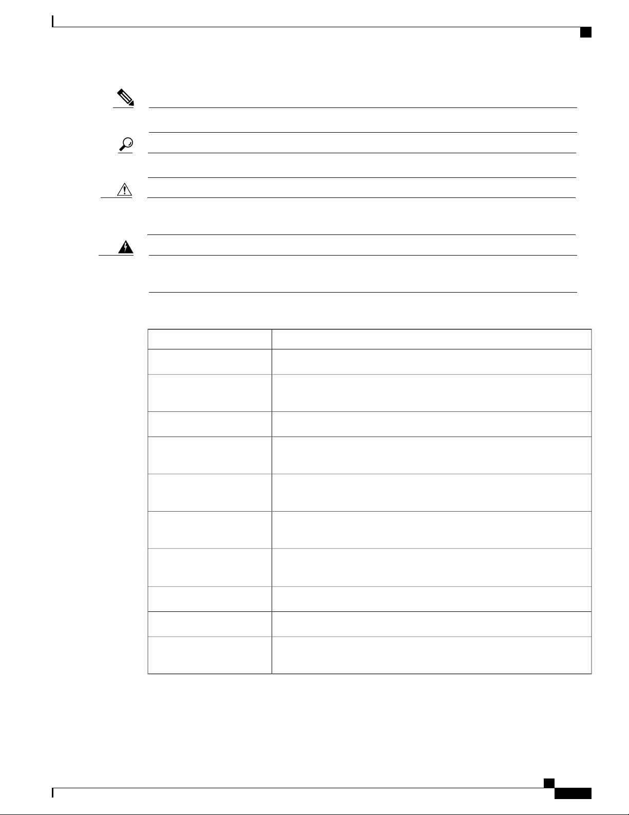
The following figure illustrates the front view of the router.
Figure 1: Cisco ASR 901S Series Aggregation Services Router—Front View
1
Upper section2Lower section (detachable, houses the cable
bay)
Lower Section
This section of the router has a door that can be opened at the OSP. It houses the cable bay and provides access
to the port interfaces and enables the ports to be serviced (like changing the optical modules, cables, and so
on), when required.
Cable Bay—The cable bay is used to route and fix the cables to the bottom panel of the router and connect
power. The FD chassis model has an onboard DC-input and the FA chassis model contains a AC power supply
unit (PSU) that is housed on the right side, inside the cable bay.
Cisco ASR 901S Series Aggregation Services Router Hardware Installation Guide
OL-29732-01 3
Page 14
Cisco ASR 901S Series Aggregation Services Router: Front View
REVIEW DRAFT - CISCO CONFIDENTIAL
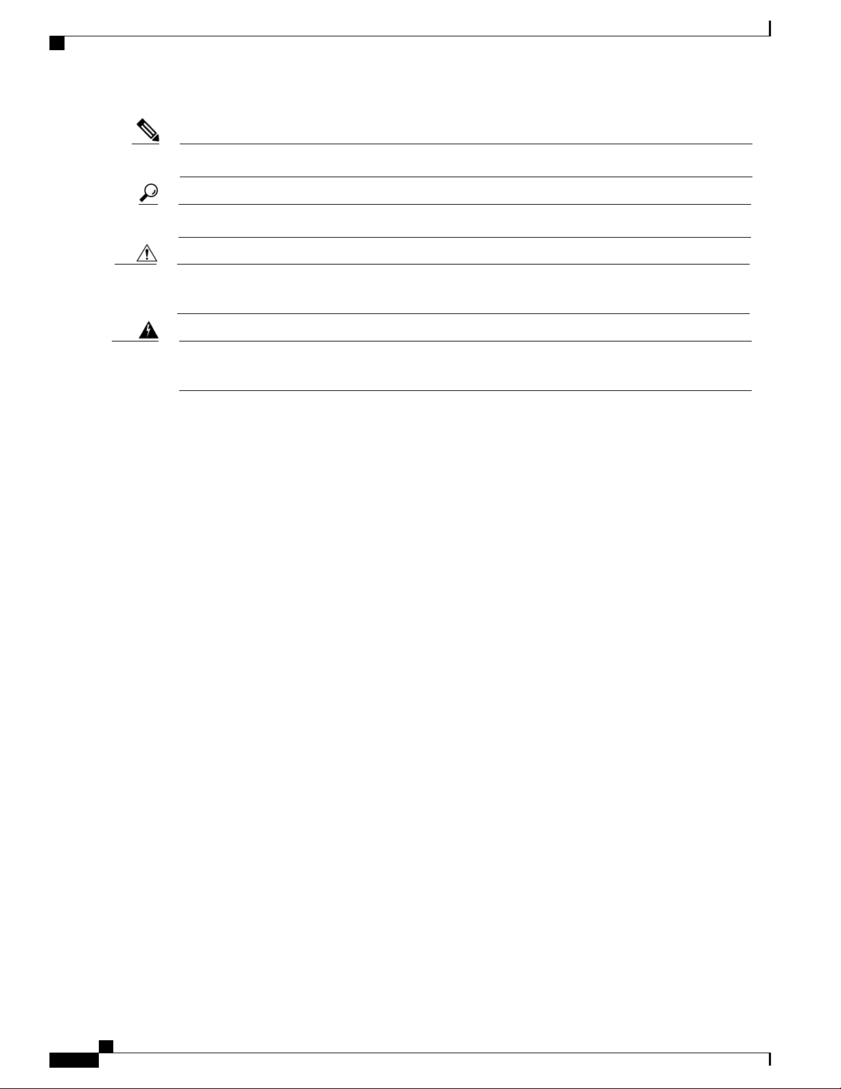
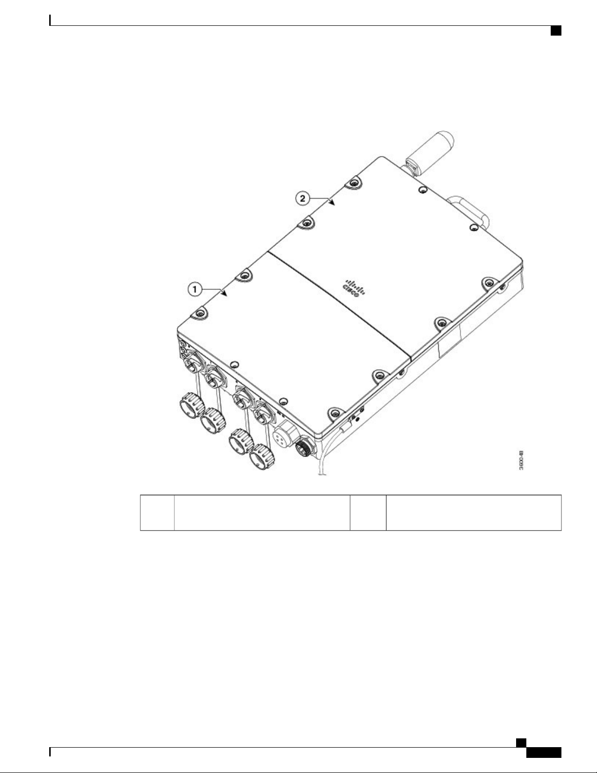
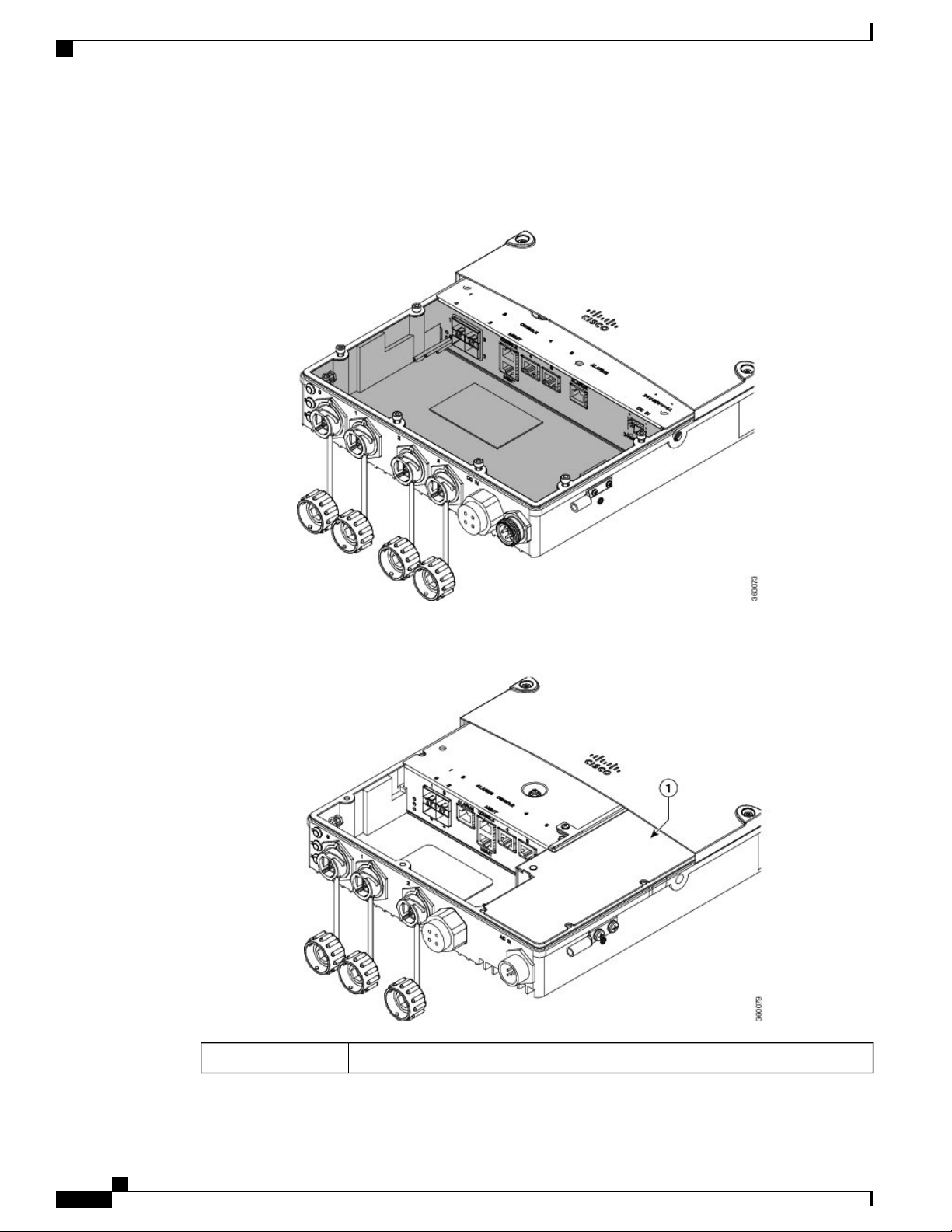
The following figures shows the open view of the cable bay of the FD and FA router chassis models.
Figure 2: Cable Bay of the FD Chassis
Introduction
Figure 3: Cable Bay of the FA Chassis
AC power supply unit1
Cisco ASR 901S Series Aggregation Services Router Hardware Installation Guide
4 OL-29732-01
Page 15
Introduction
Cisco ASR 901S Series Aggregation Services Router: Back View
REVIEW DRAFT - CISCO CONFIDENTIAL
For details about the internal interfaces available in the cable bay, see Cisco ASR 901S Series Aggregation
Services Router: Top and Bottom View, on page 5.
Cisco ASR 901S Series Aggregation Services Router: Back View
The Cisco ASR 901S Series Aggregation Services Router has an conduction-cooled fanless design. The back
panel of the router acts as the heat sink for all the components.
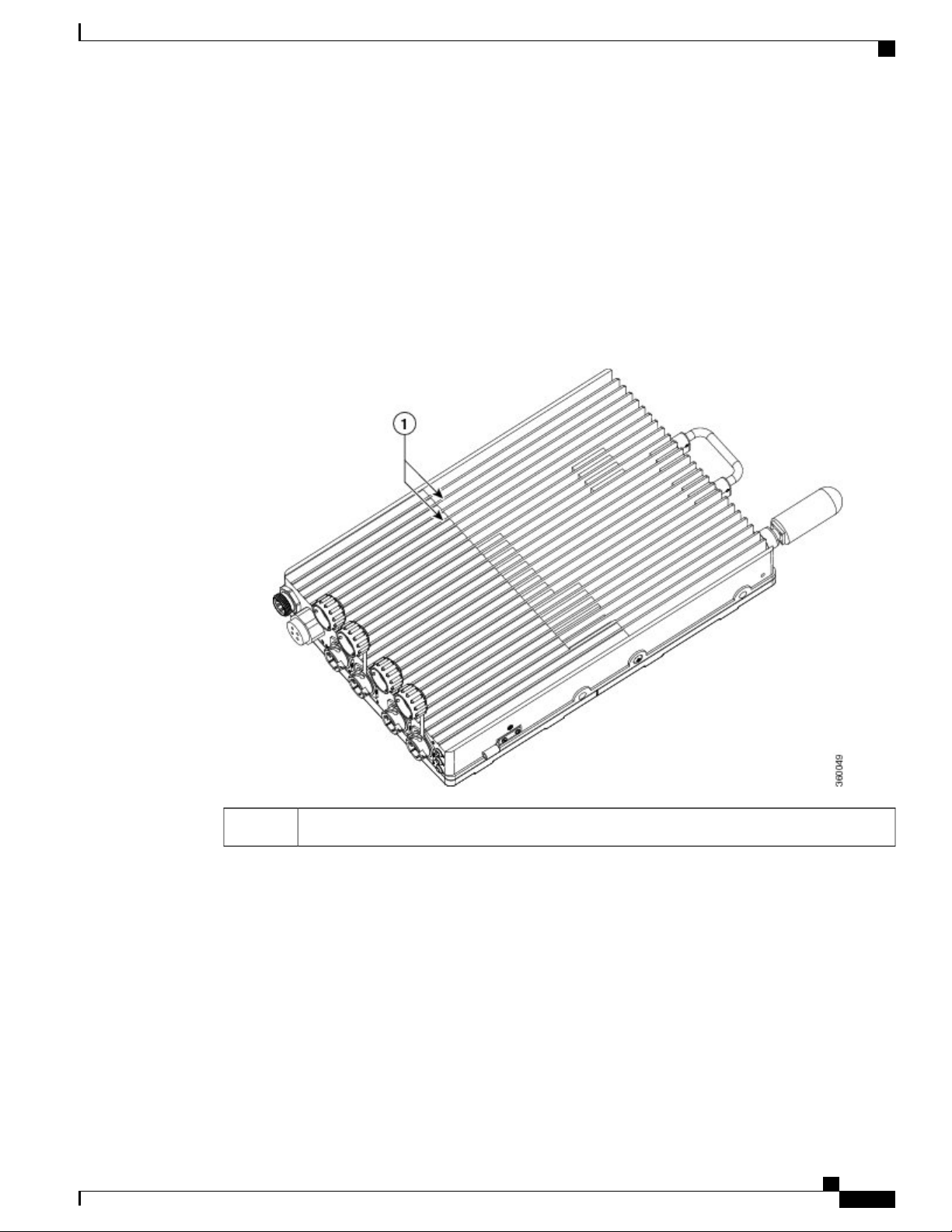
The following figure illustrates the back view of the router, with heat sink fins.
Figure 4: Cisco ASR 901S Series Aggregation Services Router—Back View
Heat sink fins1
Cisco ASR 901S Series Aggregation Services Router: Top and Bottom View
At the top of the Cisco ASR 901S Series Aggregation Services Router is an antenna connector and a handle
that helps to easily carry or remove the router.
The antenna connector provides support for integrated or external antennas. For detailed information about
the router antenna, including installation instructions, see Antenna Installation and Replacement, on page
58.
Cisco ASR 901S Series Aggregation Services Router Hardware Installation Guide
OL-29732-01 5
Page 16
Cisco ASR 901S Series Aggregation Services Router: Top and Bottom View
REVIEW DRAFT - CISCO CONFIDENTIAL
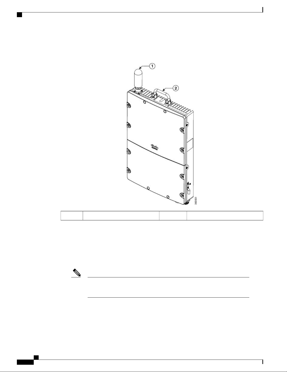
The following figure shows the top view of the router.
Figure 5: Cisco ASR 901S Series Aggregation Services Router—Top View
Introduction
Router handle2Antenna1
The bottom of the router contains the following interfaces:
•
LEDs—There are three LEDs are supported on the front plate of the router: System, Management, and
Network/Link. The LEDs can be disabled using Cisco IOS CLIs.
•
Gigabit Ethernet SFP Ports—The router supports four SFP only ports. The SFP ports support optical
1 GE ports.
Note
The SFPs supported on the Cisco ASR 901S Series Aggregation Services Router is
dependent on the router chassis model. For the list of SFPs supported on the router, see
Table 5 in Product Specifications, on page 72.
•
Cable Gland Interface Port—A cable gland interface is provided to thread management, alarm, console,
and copper RJ45 cables when installing the router.
•
Power Supply—The router is provided with a single AC power supply or DC power supply. The power
input connector is located at the bottom of the router.
Cisco ASR 901S Series Aggregation Services Router Hardware Installation Guide
6 OL-29732-01
Page 17
Introduction
Cisco ASR 901S Series Aggregation Services Router: Top and Bottom View
REVIEW DRAFT - CISCO CONFIDENTIAL
The FA model of the router is provided with a single AC power supply unit (PSU). This module supplies
54 VDC to the main board to power the main board and the power over Ethernet (POE) circuitry. The
AC PSU can provide up to 120 W power.
The FD variant of the router has a built-in DC-input. The DC power supply is compatible with the range
of DC input voltages specifically available at cell sites.
For details about the power specifications, see Table 7 in Product Specifications, on page 72.
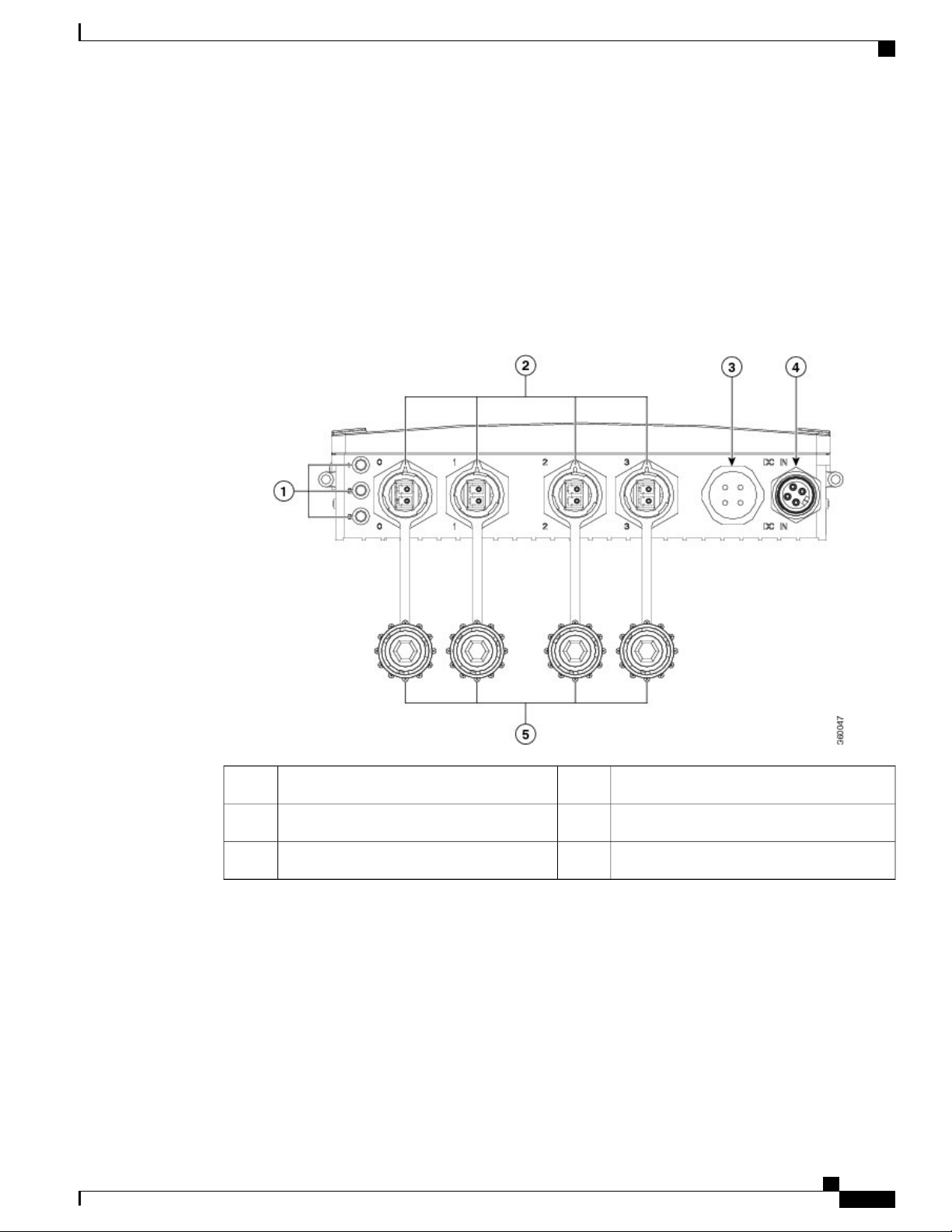
The following figures shows the bottom view of one of the FD and FA chassis models.
Figure 6: Cisco ASR 901S Series Aggregation Services Router—Bottom View (A901S-4SG-F-D)
DC power input4LEDs1
Dust caps5SFP ports2
Cable gland interface3
Cisco ASR 901S Series Aggregation Services Router Hardware Installation Guide
OL-29732-01 7
—
Page 18
Cisco ASR 901S Series Aggregation Services Router: Top and Bottom View
REVIEW DRAFT - CISCO CONFIDENTIAL
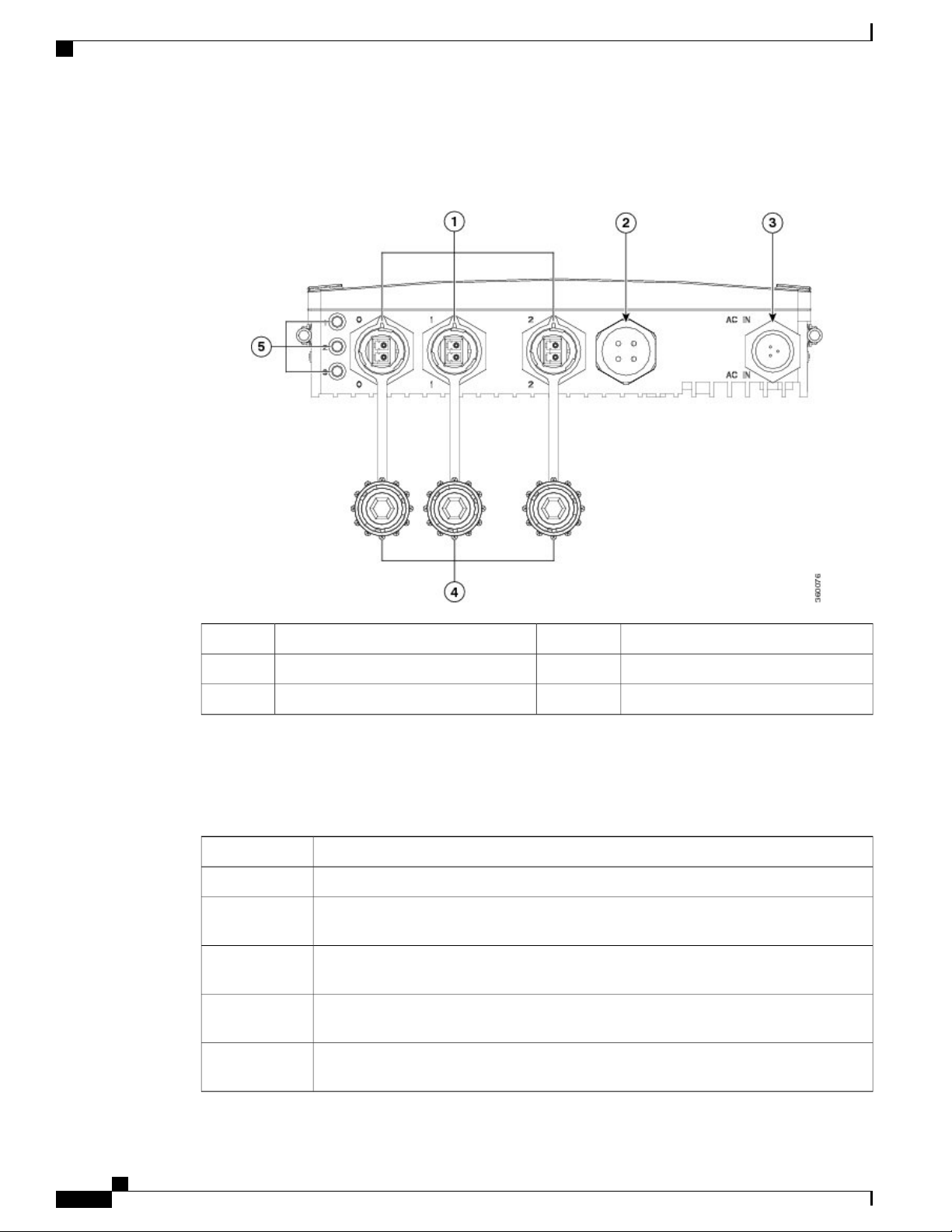
Figure 7: Cisco ASR 901S Series Aggregation Services Router—Bottom View (A901S-2SG-F-AH)
Introduction
Dust caps4SFP ports1
LEDs5Cable gland interface2
AC power input3
—
The following table provides the list of interface ports supported on Cisco ASR 901S Series Aggregation
Services Router.
Table 3: Interface Ports Supported on the Cisco ASR 901S Series Aggregation Services Router
DescriptionChassis PID
4 external SFP ports + 1 gland interface for internal ports, DC power supplyA901S-4SG-F-D
A901S-3SG-F-D
3 external SFP ports + 1 external copper (Cu) port + 1 gland interface for internal ports,
DC power supply
A901S-2SG-D
2 external SFP ports + 2 external Cu ports + 1 gland interface for internal ports, DC power
supply
A901S-3SG-F-AH
3 external SFP ports + 1 gland interface for internal ports, AC PSU, 1 sec holdover for 1
power over Ethernet plus (POE+)
A901S-2SG-F-AH
2 external SFP ports + 1 external Cu port + 1 gland interface for internal ports, AC PSU,
1 sec holdover for 1 POE+
Cisco ASR 901S Series Aggregation Services Router Hardware Installation Guide
8 OL-29732-01
Page 19
Introduction
Safety Precautions
REVIEW DRAFT - CISCO CONFIDENTIAL
The following section provides details about the internal interface ports (within the cable bay area) supported
on Cisco ASR 901S Series Aggregation Services Router.
•
Gigabit Ethernet and Fast Ethernet Ports—The router supports two Gigabit Ethernet and Fast Ethernet
Cu (RJ45) ports. The ports support standard 100/1000 Base-T Ethernet features including auto-MDIX.
•
Management Ports—The router supports two types of management port: an RS-232 serial console and
10/100 Base-T Ethernet ports. Both ports use the RJ45 connector and are accessible via the cable gland
interface. .
The RS-232 serial console port can operate with flow control signals clear-to-send and ready-to-send
◦
and without flow controls. The default baud rate is 9600 and can be reconfigured to operate at a
maximum baud rate of 115200.
The 10/100 Base-T Ethernet port can auto-negotiate or force to operate at either 10 Mbps or 100
◦
Mbps, half or full duplex. The traffic on this port is isolated from switching ports.
•
Alarm Inputs— The router supports four dry-contact alarm inputs. These alarm inputs can be configured
to trigger on open or closed, individually. Each input can be provisioned to generate minor, major, or
critical alarms.
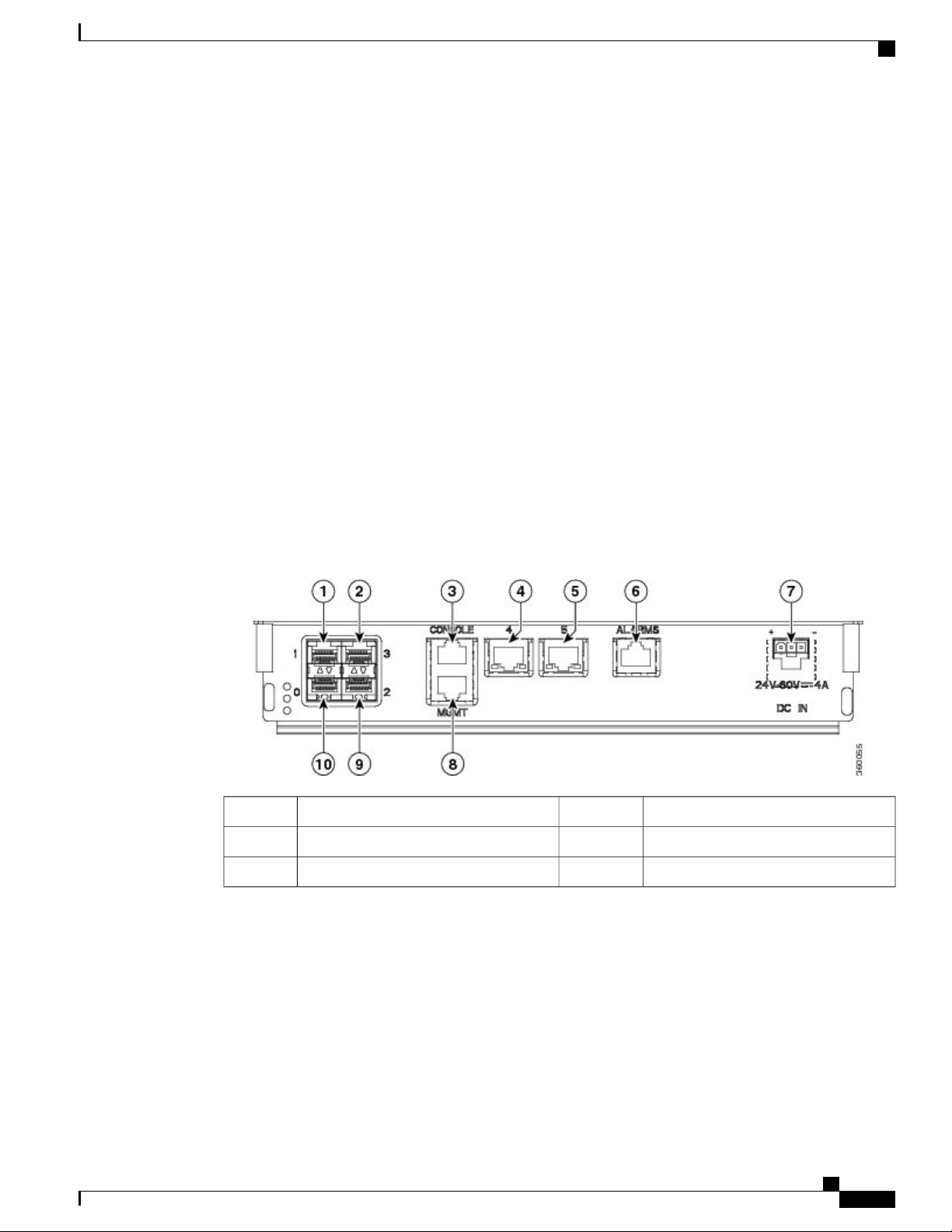
Figure 8: Cable Bay Interfaces (FD chassis)
Alarm port6SFP ports1, 2, 9, 10
DC input port7Console port3
Management port8GE ports4, 5
For the list of interfaces supported on the FD and FA chassis, see Cisco ASR 901S Series Aggregation Services
Router: Top and Bottom View, on page 5.
Safety Precautions
Observe the following general safety precautions and recommendations in planning the source power
requirements for the Cisco ASR 901S Series Aggregation Services Router (for additional safety information,
see Safety Guidelines, on page 13).
Cisco ASR 901S Series Aggregation Services Router Hardware Installation Guide
OL-29732-01 9
Page 20

Environmental Monitoring Temperature Sensor
REVIEW DRAFT - CISCO CONFIDENTIAL
Check the power at your site before router installation (and periodically after installation) to ensure clean
•
power (free of spikes and noise) is being received.
Always disconnect the power source and unplug the power cable before working on the router.
•
Install proper grounding for the site to avoid damage from lightning and power surges.
•
Introduction
Warning
Warning
To avoid electric shock, do not connect safety extra-low voltage (SELV) circuits to telephone-network
voltage (TNV) circuits. LAN ports contain SELV circuits, and WAN ports contain TNV circuits. Some
LAN and WAN ports both use RJ-45 connectors. Use caution when connecting cables. Statement 1021
There is the danger of explosion if the battery is replaced incorrectly. Replace the battery only with the
same or equivalent type recommended by the manufacturer. Dispose of used batteries according to the
manufacturer's instructions. Statement 1015
Environmental Monitoring Temperature Sensor
The Cisco ASR 901S Series Aggregation Services Routers has a temperature sensor to detect over temperature
conditions inside the chassis. The over temperature detection trips at 158°F (70°C). This condition is reported
to the processor as an interrupt, where the software generates the appropriate alarms. If the router reaches a
temperature of 181.4°F (83°C), the power supply cycles itself to prevent the router from exceeding the
maximum temperature while being powered up.
The following table provides the over temperature alert settings.
WarningThresholdDescription
Enabled181.4 to -40°F (83 to -40°C)Board temperature
Enabled181.4 to -40°F (83 to -40°C)Inlet temperature
Enabled181.4 to -40°F (83 to -40°C)CPU temperature
For environmental specifications, see table 8 in Product Specifications, on page 72.
External Connections and Chassis Cable Ports
When connecting the router internal ports to external cables or exterior devices, the router cables must be
threaded through the chassis cable ports designated for this purpose. Some chassis ports are reserved for
specific cables and remaining ports can be used based on the network configuration and cabling requirements.
For details about the interfaces, see Cisco ASR 901S Series Aggregation Services Router: Top and Bottom
View, on page 5.
The cable connectivity can be provided as follows:
Cisco ASR 901S Series Aggregation Services Router Hardware Installation Guide
10 OL-29732-01
Page 21

Introduction
External Connections and Chassis Cable Ports
REVIEW DRAFT - CISCO CONFIDENTIAL
The power input is provided on the extreme right through an IP-65 compliant gland for DC. An ordinary
•
DC cable can be routed through the gland. For AC inputs, a special IP-65 compliant connector system
should be used. The AC input cable can be removed from the system without opening the door.
Each SFP port is connected with an LC-LC patch cable from the SFP module to the bottom panel. For
•
the external connectivity, an LC cable system with IP-65 sealing should be used.
For configurations with two or three SFP ports, one or two copper ports will have an internal patch cable
•
arrangement. For these configurations, an external RJ-45 connection with IP-65 sealing should be used.
For configurations with four SFP ports, the RJ-45 connections for the copper ports with common copper
•
cables (non IP-65 compliant) should be used. These cables can be routed through the four-wire gland
shown adjacent to the power entry cable.
The alarm port has a single Cat5e cable routed through the four-wire gland.
•
The management, Ethernet, and console ports are usually not used in the OSP because the access to the
•
router is limited (the Wi-Fi interface is used instead). However, when these ports are used, the
corresponding cables should be routed through the four-wire gland.
Note
In certain configurations, like 4 SFPs, 2 CUs, and alarm, it is not possible to route the
console and management ports through the four-wire gland.
For the optical ports, multimode patch cables are supplied by default with the router. The single mode
•
cables can be ordered separately.
Cisco ASR 901S Series Aggregation Services Router Hardware Installation Guide
OL-29732-01 11
Page 22

External Connections and Chassis Cable Ports
REVIEW DRAFT - CISCO CONFIDENTIAL
Introduction
Cisco ASR 901S Series Aggregation Services Router Hardware Installation Guide
12 OL-29732-01
Page 23

Preparing to Install the Router
This chapter guides you through the process of preparing for your Cisco ASR 901S Series Aggregation
Services Router installation. It contains safety information and warnings, site preparation details and
instructions on unpacking the router. It contains the following sections:
Safety Guidelines, page 13
•
Safety Warnings, page 16
•
Prerequisites, page 16
•
Site Planning , page 17
•
Unpacking the Router, page 19
•
Safety Guidelines
Before you begin installing the Cisco ASR 901S Aggregation Services Router, review the safety guidelines
provided in the Safety Precautions, on page 9 and General Safety Information for Mounting, on page 24
to avoid injuries or damaging the equipment.
For safety and compliance information, see Table 9 in Product Specifications, on page 72.
In addition, before replacing, configuring, or maintaining the router, review the safety warnings listed in the
document Cisco Regulatory Compliance and Safety Information for Cisco ASR 901S Series Aggregation
Services Router.
CHAPTER 2
Safety with Equipment
To ensure your safety and protect the equipment, follow these guidelines. However, these guidelines may not
cover all potentially hazardous situations you may encounter during system installation, so be alert.
Before connecting the system to the power source, read the installation instructions. Statement 1004Warning
Before moving the system, always disconnect all the power cords and interface cables.
•
Never assume that power is disconnected from a circuit; always check.
•
Cisco ASR 901S Series Aggregation Services Router Hardware Installation Guide
OL-29732-01 13
Page 24

Safety with Electricity
REVIEW DRAFT - CISCO CONFIDENTIAL
Before and after installation, keep the chassis area clean and dust-free.
•
Keep tools and assembly components away from walk areas to avoid tripping over them.
•
Do not work alone in potentially hazardous conditions.
•
Do not perform any action that creates a potential hazard to people or makes the equipment unsafe.
•
Do not wear loose clothing that may get caught in the chassis.
•
When working under conditions hazardous to your eyes, wear safety glasses.
•
Safety with Electricity
Preparing to Install the Router
Warning
Warning
Warning
Warning
Warning
Before performing any of the following procedures, ensure that power is removed from the DC circuit.
Statement 1003
To avoid electric shock, do not connect safety extra-low voltage (SELV) circuits to telephone-network
voltage (TNV) circuits. LAN ports contain SELV circuits, and WAN ports contain TNV circuits. Some
LAN and WAN ports both use RJ-45 connectors. Statement 1021
Before working on equipment that is connected to power lines, remove jewelry (including rings, necklaces,
and watches). Metal objects will heat up when connected to power and ground and can cause serious burns
or weld the metal object to the terminals. Statement 43
Before working on a chassis or working near power supplies, unplug the power cord on AC units; disconnect
the power at the circuit breaker on DC units. Statement 12
There is the danger of explosion if the battery is replaced incorrectly. Replace the battery only with the
same or equivalent type recommended by the manufacturer. Dispose of used batteries according to the
manufacturer's instructions. Statement 1015
Warning
This unit might have more than one power supply connection. All connections must be removed to
de-energize the unit. Statement 1028
When working on electrical equipment, follow these guidelines:
Locate the emergency power switch. If an electrical accident occurs, you can quickly switch off the
•
power.
Before working on the system, switch off the DC main circuit breaker and disconnect the power terminal
•
block cable.
Disconnect all power before performing the following :
•
Cisco ASR 901S Series Aggregation Services Router Hardware Installation Guide
14 OL-29732-01
Page 25

Preparing to Install the Router
Preventing Electrostatic Discharge Damage
REVIEW DRAFT - CISCO CONFIDENTIAL
Working on or near power supplies.
◦
Installing or removing a router chassis or network processor module.
◦
Performing most hardware upgrades.
◦
Never install equipment that appears damaged.
•
Carefully examine your work area for possible hazards, such as wet floors, ungrounded power extension
•
cables, and missing safety grounds.
Never assume that power is disconnected from a circuit; always check.
•
Never perform any action that creates a potential hazard to people or makes the equipment unsafe.
•
If an electrical accident occurs, proceed as follows:
•
Use caution, and do not become a victim yourself.
◦
Switch off power to the router.
◦
If possible, send another person to get medical aid. Otherwise, determine the condition of the
◦
victim, and then call for help.
Determine whether the person needs rescue breathing or external cardiac compressions; then take
◦
appropriate action.
In addition, use the following guidelines when working with any equipment that is disconnected from a power
source, but still connected to telephone wiring or network cabling:
Never install telephone wiring during a lightning storm.
•
Never install telephone jacks in wet locations unless the jack is specifically designed for it.
•
Never touch un-insulated telephone wires or terminals unless the telephone line is disconnected at the
•
network interface.
When installing or modifying telephone lines, use caution.
•
Preventing Electrostatic Discharge Damage
Electrostatic Discharge (ESD) can damage equipment and impair electrical circuitry. ESD can occur when
electronic printed circuit cards are improperly handled, and can cause complete or intermittent failures. When
removing and replacing modules, always follow ESD prevention procedures:
Ensure that the router chassis is electrically connected to earth ground.
•
Wear an ESD-preventive wrist strap, ensuring that it makes good skin contact. To channel unwanted
•
ESD voltages safely to ground, connect the clip to an unpainted surface of the chassis frame. To guard
against ESD damage and shocks, the wrist strap and cord must operate effectively.
If no wrist strap is available, ground yourself by touching a metal part of the chassis.
•
Caution
OL-29732-01 15
For the safety of your equipment, periodically check the resistance value of the antistatic wrist strap. It
should be between 1 and 10 Mohm.
Cisco ASR 901S Series Aggregation Services Router Hardware Installation Guide
Page 26
Safety Warnings
REVIEW DRAFT - CISCO CONFIDENTIAL
Safety Warnings
This section contains important safety warnings for the installation and use of the router.
Translated versions of all safety warnings are available in the safety warnings document that shipped with
your router, and which is available on Cisco.com.
Preparing to Install the Router
Warning
Warning
Warning
Warning
IMPORTANT SAFETY INSTRUCTIONS
This warning symbol means danger. You are in a situation that could cause bodily injury. Before you
work on any equipment, be aware of the hazards involved with electrical circuitry and be familiar with
standard practices for preventing accidents. Use the statement number provided at the end of each warning
to locate its translation in the translated safety warnings that accompanied this device. Statement 1071
Do not work on the system or connect or disconnect cables during periods of lightning activity. Statement
1001
Installation of the equipment must comply with local and national electric codes. Statement 1074Warning
Only trained and qualified personnel should be allowed to install, replace, or service this equipment.
Statement 1030
This unit is intended for installation in restricted access areas. A restricted access area can be accessed
only through the use of a special tool, lock and key, or other means of security. Statement 1017
Class 1 laser product. Statement 1008Warning
Warning
To prevent the system from overheating, do not operate it in an area that exceeds the maximum
recommended ambient temperature of 181.4°F (83°C). Statement 1047
Prerequisites
Before installing the Cisco ASR 901S Series Aggregation Services Router, it is important to prepare for
installation by :
Preparing the site (site planning) and reviewing the installation plans or method of procedures (MOPs).
•
Unpacking and inspecting the Cisco ASR 901S Series Aggregation Services Router.
•
Cisco ASR 901S Series Aggregation Services Router Hardware Installation Guide
16 OL-29732-01
Page 27

Preparing to Install the Router
Site Planning
Ideally, you should have prepared the installation site beforehand. As part of your preparation, obtain a plan
of the site and the equipment rack where the Cisco ASR 901S Series Aggregation Services Router would be
housed. Determine the location of any existing routers and their interconnections, including communications
and power.
All personnel involved in the installation of the router including installers, engineers, and supervisors should
participate in the preparation of a Method of Procedure (MOP) for approval by the customer.
Site Environment
Every network application is a unique installation. Before installing the Cisco ASR 901S Series Aggregation
Services Router, you should perform a site survey to determine the optimum use of networking components
and to maximize range, coverage, and network performance.
Consider the following operating and environmental conditions when performing a site survey:
Site Planning
REVIEW DRAFT - CISCO CONFIDENTIAL
•
Data rates—Sensitivity and range are inversely proportional to data bit rates. The maximum radio range
is achieved at the lowest workable data rate. A decrease in receiver sensitivity occurs as the radio data
increases.
•
Antenna type and placement—Proper antenna configuration is a critical factor in maximizing radio
range. As a general rule, range increases in proportion to antenna height. However, do not place the
antenna higher than necessary, because the extra height also increases potential interference from other
unlicensed radio systems and decreases the wireless coverage from the ground.
•
Physical environment—Clear or open areas provide better radio range than closed or filled areas.
Always follow ESD-prevention procedures described in Preventing Electrostatic Discharge Damage,
on page 15 to avoid damage to equipment. Damage from static discharge can cause immediate or
intermittent equipment failure.
•
Obstructions—Physical obstructions such as buildings, trees, or hills can hinder performance of wireless
devices. Avoid locating the devices in a location where there is an obstruction between the sending and
receiving antennas.
Method of Procedure
Part of site preparation includes reviewing installation plans or method of procedures (MOPs). An example
of a MOP that includes pre-installation checklist of tasks, considerations to address and agree upon before
proceeding with the installation, is as follows:
Read this hardware installation guide.
•
Assign personnel.
•
Determine protection requirements for personnel, equipment, and tools.
•
Evaluate potential hazards that may affect service.
•
Schedule time for installation.
•
Cisco ASR 901S Series Aggregation Services Router Hardware Installation Guide
OL-29732-01 17
Page 28

Installation Checklist
REVIEW DRAFT - CISCO CONFIDENTIAL
Determine space requirements.
•
Determine power requirements.
•
Identify required procedures or tests.
•
Make a preliminary plan that locates each Cisco ASR 901S Series Aggregation Services Router that
•
you plan to install.
Verify the list of replaceable parts for installation (screws, bolts, washers, and so on).
•
Check the required tools list to make sure the necessary tools and test equipment are available (see
•
Customer-Supplied Materials and Tools, on page 29).
Perform the installation.
•
Installation Checklist
To assist you with your installation and to provide a historical record of completed tasks and users, use the
following installation checklist. Make a copy of this checklist and mark the entries as you complete each task.
When the checklist is completed, include a copy of the checklist for each router in your site log along with
other records for your new router. For information on the site log, including a sample site log, see Site Log,
on page 85.
Installation Checklist for Site:
Preparing to Install the Router
Router Name:
DateVerified byTaskSl. No.
Installation checklist copied1
Background information placed in site log2
Site power voltages verified3
Installation site power check completed4
Required tools available5
Additional equipment available6
Router received7
Documentation DVD received (if ordered)8
Cisco Information Packet publication received9
Chassis components verified10
Initial electrical connections established11
Cisco ASR 901S Series Aggregation Services Router Hardware Installation Guide
18 OL-29732-01
Page 29
Preparing to Install the Router
Unpacking the Router
REVIEW DRAFT - CISCO CONFIDENTIAL
12
ASCII terminal (for local configuration) or modem
(for remote configuration)
Signal distance limits verified13
Start-up sequence steps completed14
Initial operation verified15
Software image verified16
Unpacking the Router
Procedure
Step 1
Step 2
Step 3
Open the shipping container and carefully remove the contents.
When you unpack the router, do not remove the foam blocks attached to antennas and antenna
Tip
connectors. The foam protects the antennas and connectors during installation.
Return all packing material to the shipping container, and save it.
Note
Ensure that all items listed in Router Package Contents, on page 19 are included in the shipment. If any item
is damaged or missing, notify your authorized Cisco sales representative.
Do not discard the packaging materials used in shipping your Cisco ASR 901S Series Aggregation
Services Router. You will need the packaging materials in the future if you move or ship the router.
Router Package Contents
Your router kit contains the items listed in the following table:
DescriptionItemQty.
Cisco ASR 901S Series Aggregation Services RouterRouter1
For details about the chassis models, see Components and Options,
on page 71
For DC routers:Accessory kit1
Two-hole lug, 6-AWG ground wire, number10 blue stud (part
•
number: 32-0619-01)
Four pan-head Phillips grounding lug screws used to attach the
•
lug to the router (part number: 48-0501-01)
Cisco ASR 901S Series Aggregation Services Router Hardware Installation Guide
OL-29732-01 19
Page 30

Router Package Contents
REVIEW DRAFT - CISCO CONFIDENTIAL
DescriptionItemQty.
For AC routers:
Two-hole lug, 6-AWG ground wire number 10 blue stud (part
•
number 32-0619-01)
Four pan-head Phillips grounding lug screws used to attach the
•
lug to the router (part number: 48-0501-01)
RJ-45-to-DB-9Console cable1
Preparing to Install the Router
Grounding kit1
Optional Items (Ordered
Separately)
Pole mount kit1
Wall mount kit1
Two grounding lug and four screws
•
Paste PENA 1/2 Burndy Pentrone
•
For details, see Grounding the Router, on page 44
Pole clamp bracket
•
Two pole clamp gussets
•
Required hardware
•
For details, see Pole Mount Kit, on page 25
Mounting bracket
•
Required hardware
•
For details, see Wall Mount Bracket Kit, on page 27
Two steel straps. For details, see Band Strap Kit, on page 28Band strap kit1
BAND-IT strap tool. For details, see Strap Tool Kit, on page 28Strap tool kit1
Antenna plug1
For details about the antenna, see Antenna Installation and
Replacement, on page 58
Security tool1
Used to remove security screws from the router top cover. See Opening
the Router Door, on page 47.
1
Cisco Information Packet
publication
Inspect all items for shipping damage. If an item appears to be damaged, or if you encounter problems installing
or configuring your router, contact customer service. The Cisco Information Packet provides warranty, service,
and support information.
Cisco ASR 901S Series Aggregation Services Router Hardware Installation Guide
20 OL-29732-01
Page 31

Preparing to Install the Router
REVIEW DRAFT - CISCO CONFIDENTIAL
Installation Checklist
To assist you with your installation and to provide a historical record of completed tasks and users, use the
following installation checklist. Make a copy of this checklist and mark the entries as you complete each task.
When the checklist is completed, include a copy of the checklist for each router in your site log along with
other records for your new router. For information on the site log, including a sample site log, see Site Log,
on page 85.
Installation Checklist for Site:
Router Name:
Installation Checklist
DateVerified byTaskSl. No.
Installation checklist copied1
Background information placed in site log2
Site power voltages verified3
12
Installation site power check completed4
Required tools available5
Additional equipment available6
Router received7
Documentation DVD received (if ordered)8
Cisco Information Packet publication received9
Chassis components verified10
Initial electrical connections established11
ASCII terminal (for local configuration) or modem
(for remote configuration)
Signal distance limits verified13
Start-up sequence steps completed14
Initial operation verified15
Software image verified16
Cisco ASR 901S Series Aggregation Services Router Hardware Installation Guide
OL-29732-01 21
Page 32

Installation Checklist
Preparing to Install the Router
REVIEW DRAFT - CISCO CONFIDENTIAL
Cisco ASR 901S Series Aggregation Services Router Hardware Installation Guide
22 OL-29732-01
Page 33

CHAPTER 3
Installing the Router
This chapter describes the safety information, equipment, and procedures required to mount the Cisco ASR
901S Series Aggregation Services Router onto a vertical pole, wall, H-frame, or cabinet. This chapter contains
these sections:
Mounting Kits Overview, page 23
•
General Safety Information for Mounting, page 24
•
Contents of the Mounting Kits, page 25
•
Customer-Supplied Materials and Tools, page 29
•
Router-Mounting Instructions, page 30
•
Connecting the Chassis Ground and Power, page 43
•
Opening the Router Chassis, page 47
•
Power Connection Compliance, page 50
•
Connecting the DC Power Cable to the Router, page 50
•
AC Power Cable, page 51
•
Connecting the AC Power Cable to the Router, page 52
•
Connecting Cables, page 54
•
Antenna Installation and Replacement, page 58
•
Powering on the Router, page 61
•
Enabling Zero Touch Provisioning on the Router, page 61
•
Using CLIs for Flash Memory and Directory Procedures, page 63
•
What to Do After Installing the Hardware, page 66
•
Mounting Kits Overview
You will need some or all of the kits described in this section to install the router in the outside plant (OSP).
Your installation environment and requirements determine the kits you need.
Cisco ASR 901S Series Aggregation Services Router Hardware Installation Guide
OL-29732-01 23
Page 34

General Safety Information for Mounting
REVIEW DRAFT - CISCO CONFIDENTIAL
The includes a detailed description of each kit.
(PID)
Installing the Router
DescriptionNameCisco Product ID
-
CGR-PMK1000
CGR-PMK-BAND
AIR-BAND-INST-TL=
Wall Mount Bracket
Kit, on page 27
Pole Mount Kit, on
page 25
Band Strap Kit, on
page 28
Strap Tool Kit, on
page 28
This kit is required if your installation requires a Cisco
mounting bracket to mount the router. This kit is included
with the router accessory kit, and is used with the pole kit
and includes the hardware required to attach the mounting
bracket onto the pole clamp bracket.
This kit is required for all pole or streetlight installations
and includes a mounting bracket, pole clamp bracket, pole
clamp gusset, and the hardware required to attach the pole
clamp bracket assembly to a pole.
This kit includes two steel straps for mounting the router on
poles larger than 5 inches (14 cm) in diameter. This kit is
used together with the Pole Mount Kit, on page 25. A
Band-It Tool is required to install the steel straps on a pole.
This kit includes a Band-It tool that is required when using
steel straps to install the router on poles larger than 4.5 inches
(11.4 cm) in diameter.
General Safety Information for Mounting
Caution
Before performing any of the tasks in this chapter, read the safety warnings in this section and the Safety
Guidelines, on page 13.
Two technicians are required to properly and safely mount the router.
All mounting methods at any location are subject to the acceptance of local jurisdiction.Caution
The mounting surface, attaching screws, and optional wall anchors must be able to support 13.2 pounds
(5.99 kgs [FD chassis model with two SFPs and antenna]) or 15. 8 pounds (7.2 kgs [FA chassis model
with 2 SFPs and antenna]) static weight.
Personnel mounting the router must understand grounding methods.Caution
Cisco ASR 901S Series Aggregation Services Router Hardware Installation Guide
24 OL-29732-01
Page 35

Installing the Router
Contents of the Mounting Kits
REVIEW DRAFT - CISCO CONFIDENTIAL
Warning
Do not locate the antenna near overhead power lines or other electric light or power circuits, or where it
can come into contact with such circuits. When installing the antenna, take extreme care not to come into
contact with such circuits, as they may cause serious injury or death. For proper installation and grounding
of the antenna, please refer to national and local codes (for example, U.S.:NFPA 70, National Electrical
Code, Article 810, Canada: Canadian Electrical Code, Section 54). Statement 1052
Contents of the Mounting Kits
This section describes the contents of the mounting kits available for the router and when you should use each
kit.
Pole Mount Kit
Use the Cisco pole mount kit to install the pole clamp bracket onto any pole or streetlight. The kit supports
poles that meet the following criteria:
Size: 2 to 16 inch diameter poles
•
Cisco ASR 901S Series Aggregation Services Router Hardware Installation Guide
OL-29732-01 25
Page 36

Pole Mount Kit
REVIEW DRAFT - CISCO CONFIDENTIAL
Material: Metal, wood, or fiberglass poles
•
Figure 9: Pole Mount Kit Contents
Installing the Router
DescriptionQty.NameItem
1Pole clamp bracket1
Install pole clamp bracket onto a pole. Wall mount bracket
attaches to pole clamp.
2Pole clamp gusset2
Use the pole clamp gusset to install the pole clamp bracket
onto a pole.
4M8 x 12 screw3
4M8 spring washer4
Cisco ASR 901S Series Aggregation Services Router Hardware Installation Guide
26 OL-29732-01
Use the included hardware to attach the pole clamp bracket
onto the pole, as described in Mounting the Router onto a Pole,
on page 33.
Page 37

Installing the Router
REVIEW DRAFT - CISCO CONFIDENTIAL
Wall Mount Bracket Kit
Use the wall mount bracket kit if you require a Cisco mounting bracket. The wall mount bracket is attached
to a wall or to the pole clamp bracket assembly and then the router is installed onto the wall mount bracket.
This wall mount bracket is used with the Cisco Pole Mount Kit, on page 25.Note
Figure 10: Wall Mount Bracket Kit Contents
Wall Mount Bracket Kit
DescriptionQty.NameItem
1
bracket
OL-29732-01 27
1Wall mount
Cisco ASR 901S Series Aggregation Services Router Hardware Installation Guide
Mounts onto a wall or to a pole clamp bracket assembly, which is
installed on a pole.
Page 38

Band Strap Kit
Installing the Router
REVIEW DRAFT - CISCO CONFIDENTIAL
Band Strap Kit
8M8 x 12 screw2
3
washer
Use the straps in the Band Strap Kit when you mount the router on a pole larger than 4.5 inches (11.4 cm) in
diameter. This installation also requires the Pole Mount Kit, on page 25 and the Strap Tool Kit, on page 28.
Figure 11: Band Strap Kit Contents
8M8 spring
Use this hardware to attach the wall mount bracket to the wall or to
the pole clamp bracket, and the router to the wall mount bracket.
Assemble the pole clamp bracket, pole clamp gusset, screw, and
washer as described in Assembling the Pole Clamp Bracket and the
Pole Clamp Gusset, on page 30. Use the included hardware to attach
the pole clamp bracket onto the pole, as described in Mounting the
Router onto a Pole, on page 33 and to attach the wall mount bracket
onto the wall, as described in Mounting the Router onto a Wall, on
page 40.
DescriptionQty.Item
Steel straps21
Strap Tool Kit
Use the tool in the Strap Tool Kit to attach the steel straps included in the Strap Tool Kit, on page 28. Steel
straps are required to install the mounting plate on poles larger than 4.5 inches (11.4 cm) in diameter.
Cisco ASR 901S Series Aggregation Services Router Hardware Installation Guide
28 OL-29732-01
Page 39

Installing the Router
Customer-Supplied Materials and Tools
REVIEW DRAFT - CISCO CONFIDENTIAL
Note
The tool in the Strap Tool Kit is manufactured and supported by BAND-IT. For more information about
the tool, see www.band-it-idex.com.
Figure 12: Band Strap Kit Contents
DescriptionItem
Strap tool1
Strap tool documentation (not shown)2
Customer-Supplied Materials and Tools
You must supply some or all of these items to mount the router onto a pole or wall. The items you supply
depends on the installation procedure that you use.
Required for These ProceduresItem
13-mm box-end wrench or socket set
M8 x 12 screws and M8 spring washers
Assembling the Pole Clamp Bracket and the Pole Clamp
Gusset, on page 30
Assembling the Pole Clamp Bracket and the Pole Clamp
Gusset, on page 30
Mounting the Router onto a Wall, on page 40Drill and drill bit
Cisco ASR 901S Series Aggregation Services Router Hardware Installation Guide
OL-29732-01 29
Page 40

Router-Mounting Instructions
REVIEW DRAFT - CISCO CONFIDENTIAL
cross-recessed screws
Router-Mounting Instructions
This section includes all the procedures required to mount the router onto any supported pole type, wall, or
cabinet.
Router Orientation
Installing the Router
Grounding the Router, on page 44Phillips screwdriver, or other screwdriver for
Grounding the Router, on page 44Crimping tool or pliers
Grounding the Router, on page 44Grounding block
Grounding the Router, on page 44Grounding rod
When mounting the router, ensure that:
The router is oriented with the chassis cabling openings pointing down so the router cables can be
•
correctly connected through the openings and so the router door opens correctly.
The router is mounted with the access cover facing out.
•
Assembling the Pole Clamp Bracket and the Pole Clamp Gusset
The pole mount kit contains several parts that you must assemble prior to mounting onto a pole. First you
need to assemble two pole clamp gussets on the pole clamp bracket that are positioned for the pole diameter
Cisco ASR 901S Series Aggregation Services Router Hardware Installation Guide
30 OL-29732-01
Page 41

Installing the Router
Assembling the Pole Clamp Bracket and the Pole Clamp Gusset
REVIEW DRAFT - CISCO CONFIDENTIAL
you are using to mount the router. The following figure illustrates the pole diameter indicators and bolt holes
on the pole clamp.
Figure 13: Pole Clamp Bracket Adjustment Hole Locations
1
2 to 6 in.
•
6 to 11 in.
•
11 to 16 in.
•
Cisco ASR 901S Series Aggregation Services Router Hardware Installation Guide
OL-29732-01 31
2Pole size indicators
Bolt holes for pole diameters (11 to 16 inches
indicated)
Page 42

Assembling the Pole Clamp Bracket and the Pole Clamp Gusset
REVIEW DRAFT - CISCO CONFIDENTIAL
Procedure
Installing the Router
Step 1
Position the pole clamp gussets on the pole clamp bracket for the pole diameter you are using and secure each
pole clamp gusset with two M8 x 12 screws (with M8 spring washers). Tighten the screws to 13 to 15 ft lbs
(17.6 to 20.3 Nm). (See the following figure.)
Figure 14: Assembling the Pole Clamp Gusset onto the Pole Clamp Bracket
Pole clamp gusset3M8 x 12 screw (with M8 spring washer)1
Pole clamp bracket4M8 spring washer2
Cisco ASR 901S Series Aggregation Services Router Hardware Installation Guide
32 OL-29732-01
Page 43

Installing the Router
Mounting the Router onto a Pole
REVIEW DRAFT - CISCO CONFIDENTIAL
Step 2
Step 3
Screw the M8 screw onto the pole clamp bracket hole, and tighten just enough to prevent the bolt from falling
off as shown in the figure above.
Go to Mounting the Router onto a Pole.
Mounting the Router onto a Pole
The router can be installed where power is available, without the need for a wired LAN connection.
To mount the router onto a vertical pole or lamp-post, you need to install two metal bands around the pole to
support the router. This process requires extra tools and material not provided in the pole mount kit.
Before You Begin
Two 0.75-in. (1.9 cm) stainless steel bands
•
Banding strap tool (BAND IT) (Cisco AIR-BAND-INST-TL=)
•
Ground lug (provided with router)
•
• Crimping tool for ground lug, Panduit (http://onlinecatalog.panduit.com)
#6 AWG Ground wire
•
Procedure
Step 1
Step 2
Select a mounting location on the pole to mount the router. You can attach the router to any pole from 2 to
16 in. (5.1 to 40.6 cm) in diameter.
Note
For poles larger than 3.5 in. (8.9 cm), mount the pole clamp bracket assembly to a pole (see the following
figure) using two metal straps. Following the instructions provided with the banding strap tool (BAND IT)
(AIR-BAND-INST-TL=), loop each metal strap twice through the slots on the strap bracket.
If you will be using a streetlight power tap adapter, position the router within 3 ft (1 m) of the outdoor
light control.
Cisco ASR 901S Series Aggregation Services Router Hardware Installation Guide
OL-29732-01 33
Page 44

Mounting the Router onto a Pole
REVIEW DRAFT - CISCO CONFIDENTIAL
Installing the Router
Caution
Do not place the metal straps in the large open area between the pole clamp bracket and the
mounting plate because this does not properly secure the router.
Figure 15: Clamp Bracket Assembly Mounted on Poles Larger than 3.5 in. (8.9 cm)
Metal mounting strap3Pole clamp bracket1
Pole4Strap slot in pole clamp gusset2
Step 3
For pole diameters of 3.5 in. (8.9 cm) or less, mount the pole clamp bracket assembly to a pole using two
metal straps looped through the space between the pole clamp bracket and the pole clamp gussets (see the
Cisco ASR 901S Series Aggregation Services Router Hardware Installation Guide
34 OL-29732-01
Page 45

Installing the Router
Mounting the Router onto a Pole
REVIEW DRAFT - CISCO CONFIDENTIAL
following figure) to provide maximum holding strength for extreme environments. Following the instructions
provided with the banding strap tool (BAND IT) (AIR-BAND-INST-TL=), loop each metal strap twice.
Figure 16: Metal Strap Open Space for 3.5 in. (8.9 cm) and Smaller Poles
Metal strap open space1
Caution
Do not place the metal straps in the large open area between the pole clamp bracket and the pole
clamp gussets because this does not properly secure the router.
Step 4
Position the pole clamp bracket on the pole as needed before tightening the metal bands.
Position the pole clamp bracket on the pole as needed before tightening the metal bands.Note
Cisco ASR 901S Series Aggregation Services Router Hardware Installation Guide
OL-29732-01 35
Page 46

Mounting the Router onto a Pole
REVIEW DRAFT - CISCO CONFIDENTIAL
Installing the Router
Step 5
Step 6
Step 7
Step 8
Tighten the metal bands using the banding strap tool (BAND IT) (Cisco AIR-BAND-INST-TL=), following
the operating instructions in the box with the tool. Ensure the metal bands are as tight as possible.
Place the wall mount bracket onto the pole clamp bracket support bolt (see the following figure).
For vertical poles, position the wall mount bracket as shown in the following figure. For horizontal streetlight
poles, rotate the wall mount bracket 90 degree from the position shown in the following figure.
Install eight M8 x12 screws (with M8 spring washers) into the bolt holes.
Figure 17: Fixing the Wall Mount Bracket onto the Pole Clamp Bracket Assembly
M8 spring washers2M8 x 12 screws1
Step 9
Step 10
Hand-tighten the bolts and the nut (do not overtighten).
Adjust the top edge of the wall mount bracket until it is horizontal and tighten the screws and the flange nut
(see the above figure) to 13 to 15 ft lbs (17.6 to 20.3 Nm).
Note
The wall mount bracket can be adjusted up to 45 degrees to compensate for tilted horizontal streetlight
poles.
Cisco ASR 901S Series Aggregation Services Router Hardware Installation Guide
36 OL-29732-01
Page 47

Installing the Router
Mounting the Router onto a Pole
REVIEW DRAFT - CISCO CONFIDENTIAL
Step 11
Screw a M8 x12 bolt (with M8 spring washer) into the two support bolt holes on each side the router (see the
following figure). Do not screw the bolt all the way in. Leave a gap of approximately 0.25 in (0.635 cm).
Figure 18: Mounting the Router onto the Wall Mount Bracket on the Pole
Pole4M8 x 12 screws1
Metal straps5M8 spring washers2
Step 12
Wall mount bracket3
Position the two bolts on either side of the router with the bolt holes on the wall mount bracket (see the
—
following figure).
The router should be positioned with the LEDs on the bottom to allow viewing from the ground.Note
Cisco ASR 901S Series Aggregation Services Router Hardware Installation Guide
OL-29732-01 37
Page 48

Router Orientation When Mounting Router on a Wall
REVIEW DRAFT - CISCO CONFIDENTIAL
Figure 19: Location of Router Support Bolt Hole
Installing the Router
M8 x 12 screws (screwed onto the wall mount
bracket)
Step 13
Step 14
Step 15
Step 16
1
Screw a M8 x12 bolt (with M8 spring washers) into the second bolt hole on each side of the router (see the
above figure).
Ensure that the front of the router is vertical, and tighten the four bolts to 13 to 15 ft lbs (17.6 to 20.3 Nm).
(Optional) When using the optional Cisco external omnidirectional antenna, connect it to the router.
Hand-tighten the antenna to the router. For instructions on installing the antenna on the router, see Installing
the Chassis-Mount Antenna on the Router, on page 59.
Continue with Grounding the Router, on page 44 and Powering on the Router, on page 61.
Router Orientation When Mounting Router on a Wall
When mounting the router onto a wall, ensure that the router is oriented with the chassis cabling openings
pointing downward so the router cable hangs down.
Cisco ASR 901S Series Aggregation Services Router Hardware Installation Guide
38 OL-29732-01
Page 49

Installing the Router
Router Orientation When Mounting Router on a Wall
REVIEW DRAFT - CISCO CONFIDENTIAL
Never mount the router with the bottom (facing up) or to the side.Note
Wall-Mount Location
Identify an area on a wall that meets the safety, space, and environmental requirements.
Wall-Mount Height
The router should be mounted at a height at which you are able to view the top of the module-side panel and
at which the cables are able to be managed without adding stress to the router ports.
Wall-Mount Hardware Distance
Any reinforcement hardware you provide should be mounted to the wall with the correct distance apart so
when the bolts are installed through the mounting bracket wall mount holes (Item 1, in the following figure),
they will align with the holes in the wall.
Figure 20: Distance for Wall-Mounting Hardware
These holes can be used but a 5" tall space must
1
hands-free install
Cisco ASR 901S Series Aggregation Services Router Hardware Installation Guide
OL-29732-01 39
2Use this hole for hanging the bracket to allow
be used to offset bracket from the wall
Page 50

Mounting the Router onto a Wall
REVIEW DRAFT - CISCO CONFIDENTIAL
Mounting the Router onto a Wall
You can use the wall mount bracket as a template to mark the positions of the mounting holes for your
installation. You then install the wall mount bracket, and attach the router when you are ready. The following
section lists the material that you will need to mount the router onto a wall.
Before You Begin
Ground lug and screws (provided with the router)
•
• Crimping tool for ground lug, Panduit (http://onlinecatalog.panduit.com)
Eight M8 or 5/16 in. screws
•
Electric drill and standard screwdriver
•
#6-AWG ground wire
•
Shielded outdoor-rated Ethernet (CAT5e or better) cable
•
Grounding block
•
Installing the Router
Step 1
Grounding rod
•
13-mm box-end wrench or socket set
•
Procedure
Use the wall mount bracket as a template to mark four screw hole locations on your mounting surface. See
the following figure for the wall mount screw hole locations. You can optionally use the individual mounting
holes or the mounting slots.
Cisco ASR 901S Series Aggregation Services Router Hardware Installation Guide
40 OL-29732-01
Page 51

Installing the Router
Mounting the Router onto a Wall
REVIEW DRAFT - CISCO CONFIDENTIAL
Caution
The mounting surface, attaching screws, and optional wall anchors must be able to support 13.2
pounds (5.99 kgs [FD chassis model with two SFPs and antenna]) or 15. 8 pounds (7.2 kgs [FA
chassis model with 2 SFPs and antenna]) static weight.
Figure 21: Wall Mount Bracket for Wall-Mounting
Step 2
Use four customer-supplied screws and optional screw anchors to attach the wall mount bracket to the mounting
surface.
Note
If necessary, use suitable screw anchors and an exterior-grade plywood backboard to mount the router
to a stucco, cement, or dry wall.
Cisco ASR 901S Series Aggregation Services Router Hardware Installation Guide
OL-29732-01 41
Page 52

Mounting the Router onto a Wall
REVIEW DRAFT - CISCO CONFIDENTIAL
Installing the Router
Step 3
Hold the router inside the wall mount bracket such that the four bolts on each side of the router are aligned
with the four holes the on each side of the wall mount bracket (see the following figure).
Figure 22: Mounting the Router onto the Wall Mount Bracket on the Wall
Wall mount bracket3M8 x 12 screws1
M8 spring washers2
Cisco ASR 901S Series Aggregation Services Router Hardware Installation Guide
42 OL-29732-01
—
Page 53

Installing the Router
Connecting the Chassis Ground and Power
REVIEW DRAFT - CISCO CONFIDENTIAL
Step 4
Screw the M8 x 12 bolts in the support bolt holes on either side the router (see the above figure ). Do not
screw the bolt all the way in; leave approximately a 0.25 in. (0.635 cm) space.
Figure 23: Router in Wall Mount Bracket
Step 5
Step 6
Step 7
Ensure that the front of the router is vertical, and tighten the eight bolts to 13 to 15 ft lbs (17.6 to 20.3 Nm).
(Optional) When using the optional Cisco external omnidirectional antenna, connect it to the router point as
shown in the above figure. Hand-tighten the antenna to the router. For instructions on installing the antenna
on the router, see Installing the Chassis-Mount Antenna on the Router, on page 59.
Continue with Grounding the Router, on page 44and Powering on the Router, on page 61.
Connecting the Chassis Ground and Power
Before you connect power or turn on power to the Cisco ASR 901S Series Aggregation Services Router, you
must provide an adequate chassis ground (earth) connection to your router.
Cisco ASR 901S Series Aggregation Services Router Hardware Installation Guide
OL-29732-01 43
Page 54

Grounding the Router
REVIEW DRAFT - CISCO CONFIDENTIAL
Grounding the Router
The Cisco ASR 901S Series Aggregation Services Router provides a grounding point on either side of the
unit for a 2-hole lug.
Installing the Router
Caution
Warning
Warning
Before making connections to the Cisco ASR 901S Series Aggregation Services Router, ensure that you
disconnect the power at the circuit breaker. Otherwise it may result in severe injury to yourself, or damage
to the router.
This equipment must be grounded. Never defeat the ground conductor or operate the equipment in the
absence of a suitably installed ground conductor. Contact the appropriate electrical inspection authority
or an electrician if you are uncertain that suitable grounding is available. Statement 1024
Use copper conductors only. Statement 1025Warning
When installing the unit, the ground connection must always be made first and disconnected last. Statement
42
Cisco ASR 901S Series Aggregation Services Router Hardware Installation Guide
44 OL-29732-01
Page 55

Installing the Router
Grounding the Router
REVIEW DRAFT - CISCO CONFIDENTIAL
The following figure shows the grounding point marked on the right side of the Cisco ASR 901S Series
Aggregation Services Router for ease of installation.
Figure 24: Grounding Point on the Router
Grounding point lug cable1
This unit is to be installed in a restrictive access location and must be permanently grounded to a minimum
6-AWG copper ground wire.
Perform the steps given below to ground the Cisco ASR 901S Series Aggregation Services Router using a
2-hole lug and the corresponding mounting point. Most routers require a 6-AWG ground connection. Verify
your router requirements for the ground connection.
Before You Begin
To ensure the chassis ground connection that you provide is adequate, you need the following parts and tools:
Ratcheting torque screwdriver with Phillips head that exerts up to 15 pound-force inches (lbf-in) of
•
pressure for attaching the ground wire to the router.
Crimping tool as specified by the ground lug manufacturer.
•
16-AWG copper wire for the power cord
•
Cisco ASR 901S Series Aggregation Services Router Hardware Installation Guide
OL-29732-01 45
Page 56

Grounding the Router
REVIEW DRAFT - CISCO CONFIDENTIAL
Appropriate wire-stripping tools
•
Procedure
Installing the Router
Step 1
Step 2
Step 3
Step 4
Step 5
In the accessory kit, locate the 2-hole lug, 2 pan-head Phillips head screws used to attach the lug to the router,
and the 6-AWG ground wire. (Lug, screws, and wire are part number 32-0629-01.)
Set the parts aside.
If your ground wire is insulated, use a wire-stripping tool to strip the ground wire to 0.5 inch ± 0.02 inch (12.7
mm ±0.5 mm) for the ring terminal (see the following figure).
Figure 25: Stripping a Ground Wire
Slide the open end of the ground lug over the exposed area of the ground wire.
Using a crimping tool (as specified by the ground lug manufacturer), crimp the ground lug to the ground wire
(as shown in the following figure).
Figure 26: Crimping a Ground Lug onto the Ground Wire
Step 6
Use a Phillips head screwdriver to attach the ground lug and wire assembly with the two screws from the
accessory kit.
Step 7
Step 8
Cisco ASR 901S Series Aggregation Services Router Hardware Installation Guide
46 OL-29732-01
Connect the other end of the ground wire to a suitable grounding point at your site.
Repeat steps 3 to 7 to attach the cable to the ground lug on the left side of the router.
Page 57

Installing the Router
REVIEW DRAFT - CISCO CONFIDENTIAL
Opening the Router Chassis
This section describes how to open the Cisco ASR 901S Series Aggregation Services Router door so that you
can access the interior of the chassis.
To access the router interior, you must open the router door that is located in the lower section of the front
panel of the router chassis. Many of the router hardware installation tasks require you to open the router door
and access the router interior to install or change cables, optical modules, and so on).
Opening the Router Door
The router door can be opened while the router is powered on and connected to the network. Take any safety
precautions described in the Safety Guidelines, on page 13.
The router door features four captive, M8 bolts and two M3 bolts (see following figure).
Opening the Router Chassis
Cisco ASR 901S Series Aggregation Services Router Hardware Installation Guide
OL-29732-01 47
Page 58

Opening the Router Door
We recommend that you loosen and tighten the door bolts in the order as shown in the following figure.
Figure 27: Recommended Order of Loosening and Tightening Bolts
Installing the Router
REVIEW DRAFT - CISCO CONFIDENTIAL
The chassis door features an environmental seal that protects the chassis against environmental elements when
the door is closed. This seal creates pressure, which can cause the door to open suddenly when the last bolt
is loosened.
Before You Begin
You must provide a 1/2-inch (13 mm) socket wrench to open and close the router chassis door.
Cisco ASR 901S Series Aggregation Services Router Hardware Installation Guide
48 OL-29732-01
Page 59

Installing the Router
Closing the Router Door
REVIEW DRAFT - CISCO CONFIDENTIAL
Procedure
Step 1
To open the router door, use the socket wrench to loosen all six captive bolts in the order shown in the following
figure.
Figure 28: Router Door, Showing Captive Bolts
Step 2
After all six bolts are loose, remove the door.
Closing the Router Door
Before You Begin
When closing the door, alternate tightening bolts on each side of the chassis, in the order shown in the section
Opening the Router Door, on page 47, to evenly seal the door.
Cisco ASR 901S Series Aggregation Services Router Hardware Installation Guide
OL-29732-01 49
Page 60

Power Connection Compliance
Procedure
Installing the Router
REVIEW DRAFT - CISCO CONFIDENTIAL
Step 1
Step 2
Step 3
Verify that the door seal is clean and that all cables are tucked back into the chassis.
To close the door, use the socket wrench to evenly tighten all six bolts in the order as shown in the section
Opening the Router Door, on page 47.
Evenly tighten the bolts again, this time using 6 to 7 foot-pounds of torque.
Power Connection Compliance
Warning
Before performing any of the following procedures, ensure that power is removed from the DC circuit.
Statement 1003
Use copper conductors only. Statement 1025Warning
The installation must comply with the 2002 National Electric Code (NEC) and other applicable codes.Note
Connecting the DC Power Cable to the Router
When powering the router with DC power, you must ensure that DC power can be conveniently removed
from the unit. The power should not be removed by disconnecting the DC power connector on the unit.
Warning
Warning
A readily accessible two-poled disconnect device must be incorporated in the fixed wiring. Statement
1022
Connect the unit only to DC power source that complies with the safety extra-low voltage (SELV)
requirements in IEC 60950 based safety standards. Statement 1033
Before You Begin
To connect a DC power cable, you need to supply these tools and material:
Shielded outdoor-rated DC power cable (minimum 18 AWG) with outside cable diameter of 0.20 to
•
0.35 inch (0.51 to 0.89 cm).
Adjustable or open-end wrench
•
Small flat screw driver
•
Four-pin DC power connector (Cisco supplied)
•
Cisco ASR 901S Series Aggregation Services Router Hardware Installation Guide
50 OL-29732-01
Page 61

Installing the Router
AC Power Cable
REVIEW DRAFT - CISCO CONFIDENTIAL
Procedure
Step 1
Step 2
Step 3
Before connecting DC power to the router, ensure that the ground is connected to the router (see Grounding
the Router, on page 44).
Turn off all power sources to the router, including the DC power source.
Caution
Connect the DC power connector to the DC input plug (see the following figure) on the bottom of the router.
Figure 29: DC Power Connector
When installing DC power to the router, always connect the router of the cable FIRST. When
removing the DC power connector, always disconnect the router end of the cable LAST.
AC Power Cable
The router supports the Cisco AC power cable that is shipped with the unit. One end of the cable has the router
AC power connector; the other end is unfinished and you must provide and attach an AC power plug, or
terminate the cable at your installation site. The AC power plug or termination method you use depends on
the power source, such as a junction box, at your site.
If you attach an AC power plug:
Use a plug that complies with local and national electrical codes.
•
Verify the connection between the cable and plug is weatherproof.
•
You might have to cut the cable if a specific cable length is needed for your installation.
Caution
OL-29732-01 51
Ensure that the power source is OFF before connecting or disconnecting the power cord wires from the
power source.
Cisco ASR 901S Series Aggregation Services Router Hardware Installation Guide
Page 62

Connecting the AC Power Cable to the Router
REVIEW DRAFT - CISCO CONFIDENTIAL
Installing the Router
Caution
To attach the appropriate connector the AC power cable, follow the manual or other instructions provided
by the electrical equipment vendor, ensuring that you comply with the electrical codes for your installation
location.
Figure 30: Router AC Power Cable (Router Connector End)
Connecting the AC Power Cable to the Router
Before You Begin
When connecting the router to AC power, you must ensure that the following conditions are met:
AC power can be readily and conveniently removed from the router. The power should not be removed
•
by disconnecting the AC power connector on the unit. It should be removed by disabling AC power at
the power circuit.
Warning
Caution
The plug-socket combination must be accessible at all times, because it serves as the main disconnecting
device. Statement 1019
Before connecting or disconnecting the power cord, you must remove AC power from the power cord
using a suitable service disconnect.
You must protect AC power plugs and AC receptacles from water and other outdoor elements. You can
•
use a UL-listed waterproofing enclosure suitable for covering the AC receptacle and AC power plug
that supplies power to the unit, as described in Article 406 of the National Electric Code (NEC).
Cisco ASR 901S Series Aggregation Services Router Hardware Installation Guide
52 OL-29732-01
Page 63

Installing the Router
Connecting the AC Power Cable to the Router
REVIEW DRAFT - CISCO CONFIDENTIAL
When you install the unit outdoors, or in a wet or damp location, the AC branch circuit that powers the
•
unit should have ground fault protection (GFCI), as required by Article 210 of the NEC.
If the power cord goes through a metal cover, a bushing should be installed to prevent fraying of the
•
cord. When using a strain relief bushing, you should follow these recommendations:
Use properly sized parts
◦
Use bushings that are safety certified
◦
Use parts that are suitable for outdoor installation
◦
Ensure that the user-supplied AC power plug is certified for outdoor use and has a minimum IP67 rating.
•
Note
Caution
Step 1
Step 2
Step 3
Step 4
Step 5
Step 6
To meet EN/IEC60950-22 (Clause 4.2) requirements, ensure that additional protection is provided external
to this equipment to reduce transient surges from Overvoltage IV to Overvoltage Category II at the AC
power input of the router. The overvoltage and fault-current protection components used to achieve this
protection must comply with the IEC 61643 series of standards. To meet CAN/CSA-C22.2 No.
60950-22-07/UL60950-22 requirements, use alternative components to provide this additional protection.
Those components may comply with ANSI/IEEE C62.11, CSA Certification Notice No. 516, CSA C22.2
No. 1, or UL 1449. Suitability of the components for the application must be determined for the intended
installation. (For example, some devices are suitable for installation on the load side of the service entrance
only, and some are suitable for use with cord-connected equipment only.)
When connecting the router AC power connector, always connect the router end of the cable first. When
removing the AC power connector, always disconnect the router end of the cable last.
Procedure
Verify that the unit is grounded as described in Grounding the Router, on page 44.
Turn off power to the AC power source at the designated circuits.
Align the notch in the AC power cable with the key in the router AC power connector, then push the cable
connector into the router connector. When the cable connector is fully seated, rotate the cable connector ring
clockwise until hand-tight.
Confirm that the router antenna is connected to the router before you apply power to the router.
Connect the other end of the AC power cable to the power source, using the instructions that came with the
connecting device.
Turn on AC power at the designated circuits. The router will power on and boot the software image.
Cisco ASR 901S Series Aggregation Services Router Hardware Installation Guide
OL-29732-01 53
Page 64

Connecting Cables
REVIEW DRAFT - CISCO CONFIDENTIAL
Connecting Cables
This section describes how to connect the Cisco ASR 901S Series Aggregation Services Router to external
devices and networks. Follow the procedures in this section based on your network configuration and
requirements.
Using Cable Glands
This section describes how to use cable glands with router cables that are threaded through the chassis cable
ports.
Installing the Router
Caution
Cables must be a minimum of 0.20 inches in diameter to create an adequate seal within the cable glands.
Using smaller cables could result in an inadequate seal and therefore expose the router interior to
environmental elements.
Ordering Cisco Cable Glands
You can order a cable gland from Cisco using the model number 51-6436-01.
Tools You Supply
33-mm A/F suitable wrench to remove the hexagonal lock nut from the router
•
15/16-inch (24 mm) open-end wrench
•
Figure 31: Cable Gland Components
DescriptionNameItem
Connects directly to the chassis cable port on the routerAdapter gland1
Fits over the cable and creates an liquid-tight seal inside the glandsSplit gasket2
Secures the split gasket over the cableGrommet/lock nut3
Cable Requirements
Cisco ASR 901S Series Aggregation Services Router Hardware Installation Guide
54 OL-29732-01
Page 65

Installing the Router
REVIEW DRAFT - CISCO CONFIDENTIAL
Cables used with the cable glands should meet the following criteria:
Outdoor-rated
•
UV-stabilized
•
Diameter of 0.20-0.23 inches (5.0-5.8 mm)
•
Using Cable Glands
Caution
Cables must be a minimum of 0.20 in. in diameter to create an adequate seal within the cable glands. Using
smaller cables could result in an inadequate seal and therefore expose the router interior to environmental
elements.
Installing Cable Glands
Follow these steps for every cable that you will connect through the chassis cable ports on the router. Step 4
and Step 5 can be done ahead of time and the prepared cable gland assembly can be transported to the router
installation site.
The cable glands components referred to in this section are shown in the figure above.
The steps in the following procedure are the same for all cable types.Note
Procedure
Step 1
Step 2
Step 3
Step 4
Step 5
Verify that the cable you are using meets the requirements described in requirements section above.
Remove the dust cap from the port on the router.
Note
Billet plugs (part number, 51-6438-01) are used in the unused ports of the cable gland because dust
caps cannot be used when a cable gland port is in use.
Use your hands to attach the cable glands adapter (see figure in Using Cable Glands, on page 54) into the
chassis cable port on the router.
Insert the terminated cables through the cable gland adapter.
Thread the following cable glands components over the cable in this order:
Split gasket
•
Grommet
•
Billet plug (in case of unused gland ports)
•
Step 6
Slide the split gasket along the cable and into the grommet, pressing firmly to ensure the gasket is completely
seated in the grommet.
Step 7
Step 8
Align and press the grommet-gasket assembly into the adapter gland.
Hand-tighten, then use the open-end wrench to tighten until the split gasket seals around the cable (6 to 7
foot-pounds of torque). There should be 5-10 pounds of cable pull support.
Note
The cable glands supports up to four terminated cable connectors. Repeat steps 4 to 9 to thread
additional cable connectors.
Step 9
OL-29732-01 55
Insert the billet plugs into the unused ports of the cable gland adapter to seal it as per IP65 standards.
Cisco ASR 901S Series Aggregation Services Router Hardware Installation Guide
Page 66

Connecting the Console Port
REVIEW DRAFT - CISCO CONFIDENTIAL
Connecting the Console Port
To configure the router through the Cisco IOS CLI, you must establish a connection between the router console
port and either a terminal or a PC. The console port is located on the router interior is labeled CONSOLE.
The Cisco ASR 901S Series Aggregation Services Router has a single console port that functions as a
DTE-mode console (terminal) port for connecting a console terminal. Use this port to connect a PC terminal,
enabling you to log directly into the router system software to perform configuration or other commands.
Installing the Router
Note
The console port functions are asynchronous serial ports; any devices connected to the console port must
be cabled for asynchronous transmission. (Asynchronous is the most common type of serial device; for
example, most modems are asynchronous devices.)
The Cisco ASR 901S Series Aggregation Services Router uses a RJ-45 port for the console port function.
Complete the following steps to connect a terminal or a PC running terminal emulation software to the console
port on the router:
Procedure
Step 1
Step 2
Connect the terminal using an RJ-45 rollover cable and an RJ-45-to-DB-25 or RJ-45-to-DB-9 adapter (labeled
TERMINAL) to the console port. For cable pinouts, see Connecting Console Port and Pinouts.
Note
Configure the terminal or terminal emulation software for 9600 baud, 8 data bits, no parity, and 2 stop bits.
Note
The RJ-45-to-DB-25 adapter (Cisco part number 29-0810-01) can be purchased from Cisco Systems,
Inc.
Hardware flow control is not possible on the console
port.
Connecting Network Cables
This section describes how to connect the following router interfaces:
Connecting Gigabit Ethernet Interface Cables
The RJ-45 port supports standard straight-through and crossover Category 5 (Cat5), shielded twisted pair
(STP) cable.
Note
Cisco ASR 901S Series Aggregation Services Router Hardware Installation Guide
56 OL-29732-01
The Cisco ASR 901S Aggregation Services Router is not shipped with Category 5 STP cables; these
cables are available commercially and need to be procured.
Before You Begin
Cat5 STP cable
Page 67

Installing the Router
Dressing Router Cables
REVIEW DRAFT - CISCO CONFIDENTIAL
Procedure
Step 1
Step 2
Step 3
Ensure that the router is powered off.
Connect one end of the Cat5 STP cable to the GE port on the router.
Connect the other end to the BTS patch or demarcation panel at your site.
Connecting SFP Cables
Before You Begin
SFP module patch cable required
Procedure
Step 1
Step 2
Step 3
Step 4
Ensure that the router is powered off.
Insert the SFP module patch cable into the slot until you feel the connector on the cable snap into place in the
rear of the slot.
Connect the other end to the patch or demarcation panel at your site.
Turn on power to the router (for more details, see Powering on the Router, on page 61).
Connecting to the Alarm Port
Use a straight cable to connect to the alarm port. For details on the pinouts, see Alarm Port Pinouts, on page
83.
Connecting to the Management Ethernet Port
Use a straight or a cross over ethernet cable to connect to the management ethernet port. For details on the
pinouts, see Management Ethernet Port Pinouts, on page 83.
Dressing Router Cables
Ensure all Cisco router cables are properly insulated so as not to interfere with each other or other pieces of
equipment. Use local practices to ensure that the cables attached to your router are properly insulated.
To continue the installation, proceed to Powering on the Router, on page 61.
Cisco ASR 901S Series Aggregation Services Router Hardware Installation Guide
OL-29732-01 57
Page 68

Antenna Installation and Replacement
REVIEW DRAFT - CISCO CONFIDENTIAL
Antenna Installation and Replacement
Depending on the configuration you specified, the router could arrive in the shipping container with the
required Wi-Fi antenna packed separately. The router Wi-Fi link enables users to connect to the router from
anywhere within Wi-Fi range. For example, a technician can check the status of the router from the ground
(instead of having to physically open the router on its pole-top installation) by remotely connecting to the
router over the Wi-Fi link.
For detailed technical information about the Wi-Fi antenna, see Antenna Specifications, on page 76.
You may need to install or replace an antenna when:
You purchase a module separately from the router. The antenna is included with the module, and must
•
be installed on the router to complete the module installation.
You purchase an antenna separately to replace a faulty or damaged antenna.
•
Unused Antenna Ports
Liquid-tight, female N-connector is installed in any unused antenna port. The N-connector protects the router
interior from environmental elements including water, heat, cold, and dust. A port plug installed in the unused
antenna port before the router is shipped.
When you install or replace an antenna remove the port plug as illustrated in the following figure.
Installing the Router
Figure 32: Antenna Port Plug
Cisco ASR 901S Series Aggregation Services Router Hardware Installation Guide
58 OL-29732-01
Page 69

Installing the Router
Installing the Chassis-Mount Antenna on the Router
REVIEW DRAFT - CISCO CONFIDENTIAL
There are two antenna-mounting configurations available for the ASR 901S Series Aggregation Services
Router:
•
Direct Chassis-Mount Antennas—Install the chassis-mounted antenna directly to the antenna port.
For instructions on installing the antenna on the router, see Installing the Chassis-Mount Antenna on
the Router, on page 59.
•
External-Mount Antennas—Connect the supported Cisco lightening arrestor to the N-connector, and
then use the antenna feeder cable to connect the antenna (female N-connector) and lightning arrestor.
Installing the Chassis-Mount Antenna on the Router
The antenna is vertically polarized. Because the antenna has vertical gain, it is very important to mount the
antenna in a vertical (not leaning) position for optimal performance.
Before You Begin
Direct chassis-mount antenna
Cisco ASR 901S Series Aggregation Services Router Hardware Installation Guide
OL-29732-01 59
Page 70

Installing the Chassis-Mount Antenna on the Router
REVIEW DRAFT - CISCO CONFIDENTIAL
Procedure
Installing the Router
Step 1
Step 2
Step 3
Remove the antenna port plug located at top of the router.
Connect the N-type male connector end of the antenna through the N-type female connector in the antenna
holder.
Turn the antenna connector clock-wise to screw the antenna as shown in the following figure.
Figure 33: Installing the Antenna on the Router
N-type female connector2Antenna1
Cisco ASR 901S Series Aggregation Services Router Hardware Installation Guide
60 OL-29732-01
Page 71

Installing the Router
REVIEW DRAFT - CISCO CONFIDENTIAL
Powering on the Router
Powering on the Router
Warning
Warning
Do not touch the power supply when the power cord is connected. For systems with a power switch, line
voltages are present within the power supply even when the power switch is off and the power cord is
connected. For systems without a power switch, line voltages are present within the power supply when
the power cord is connected. Statement 4
This equipment is intended to be grounded. Ensure that the host is connected to earth ground during normal
use. Statement 39
Checklist for Power on
Securely mount the router.
•
Properly connect the power, network, and interface cables.
•
Interpreting Bottom-Panel LEDs
The Cisco ASR 901S Aggregation Services Router provides three LEDs on the bottom panel to monitor
conditions and to aid in troubleshooting problems. For a description of the LEDs, see Reading LEDs , on
page 70.
Complete these steps to power on the Cisco ASR 901S Aggregation Services Router and verify its initialization
and self-test:
Procedure
Step 1
Step 2
Remove the tape from the circuit breaker switch handle.
Restore power by moving the handle of the circuit breaker to the ON position.
The System LED on the bottom panel should go ON.
Depending on your installation, the other bottom-panel LEDs can also come on.
If you encounter problems when you power on the router, see the Troubleshooting, on page 67.
Enabling Zero Touch Provisioning on the Router
Before You Begin
Phillips screwdriver
•
Straightened paperclip or thin non-metallic pin no larger than 3/16 inches in diameter
•
Cisco ASR 901S Series Aggregation Services Router Hardware Installation Guide
OL-29732-01 61
Page 72

Enabling Zero Touch Provisioning on the Router
REVIEW DRAFT - CISCO CONFIDENTIAL
Procedure
Installing the Router
Step 1
Step 2
Use a Phillips screwdriver to remove the zero touch provisioning (ZTP) reset button screw. Be careful not to
loose the screw.
Use a straightened paperclip, thin non-metallic pin, or thin non-metallic pin no larger than 3/16 inches in
diameter and push the ZTP reset button for 0.5 seconds to initiate zero touch provisioning. (See the following
figure.)
Figure 34: Accessing the ZTP Reset Button
ZTP reset button1
Push the ZTP reset button for more than 8 seconds to reboot (power cycle); all LEDs will turn off for
approximately 5 seconds, and then the LEDs will reactivate.
Step 3
Cisco ASR 901S Series Aggregation Services Router Hardware Installation Guide
62 OL-29732-01
Replace the reset button screw and use a Phillips screwdriver to tighten to 22 to 24 in. lbs (2.49 to 2.71 Nm).
Page 73

Installing the Router
Using CLIs for Flash Memory and Directory Procedures
REVIEW DRAFT - CISCO CONFIDENTIAL
Using CLIs for Flash Memory and Directory Procedures
The following sections contain the formatting procedures for flash memory and file and directory procedures
using Cisco IOS CLIs.
Formatting Procedures for Flash Memory
We recommend that you erase the (Class B) flash memory to initialize with a Class B flash file system.
The Class B flash file system is also known as the low end file system (LEFS).
Formatting Flash Memory as a DOS File System
To format the flash memory or to remove the files from it, use the erase flash: command.
The following is sample output for formatting the flash memory, formatted with a Class B flash file system:
Router# erase flash :
Erasing the flash filesystem will remove all files! Continue? [confirm]
eeeeeeeeeeeeeeeeeeeeeeeeeeeeeeeeeeeeeeeeeeeeeeeeeeeeeeeeeeeeeeeeeeeeeeeeeeeeeeeeeeeeeee
eeeeeeeeeeeeeeeeeeeeeeeeeeeeeeeeeeeeeeeeeeeeeeeeeeeeeeeeeeeeeeeeeeeeeeeeeeeeeeeeeeeeeee
eeeeeeeeeeeeeeeeeeeeeeeeeeeeeeeeeeeeeeeeeeeeeeeeeeeeeeeeeeeeeeeeeeeeeeeeeeeeeeeeeeeeeee
eeeeeeeeeeeeeeeeeeeeeeeeeeeeeeeeeeeeeeeeeeeeeeeeeeeeeeeeeeeeeeeeeeeeeeeeeeeeeeeeeeeeeee
eeeeeeeeeeeeeeeeeeeeeeeeeeeeeeeeeeeeeeeeeeeeeeeeeeeeeeeeeeeeeeeeeeeeeeeeeeeeeeeeeeeeeee
...erased
Erasing device
File and Directory Procedures
The following sections describe file and directory procedures for flash memory, formatted with a Class B
flash file system.
Copying Files
To copy files to another location, use the copy tftp:flash: command.
The following is sample output for copying the file from an external location to the internal flash memory.
Router# copy tftp: flash
Address or name of remote host []? 10.64.71.240
Source filename []? /ngmwr-advipservicesk9-mz
Destination filename [ngmwr-advipservicesk9-mz]?
Accessing tftp://10.64.71.240//ngmwr-advipservicesk9-mz...
Erase flash: before copying? [confirm]n
Loading /ngmwr-advipservicesk9-mz from 10.64.71.240 (via FastEthernet0/0):
!!!!!!!!!!!!!!!!!!!!!!!!!!!!!!!!!!!!!!!!!!!!!!!!!!!!!!!!!!!!!!!!!!!!!!!!!!!!!!!!!!!!!!!!!!
!!!!!!!!!!!!!!!!!!!!!!!!!!!!!!
Cisco ASR 901S Series Aggregation Services Router Hardware Installation Guide
OL-29732-01 63
Page 74

File and Directory Procedures
REVIEW DRAFT - CISCO CONFIDENTIAL
[OK - 30480936 bytes]
Verifying checksum... OK (0xA6AD)
30480936 bytes copied in 196.968 secs (154751 bytes/sec)
Displaying Contents of the Flash Memory
To display the contents (directories and files) of the flash memory formatted with a Class B flash file system,
use the dir: command.
The following is sample output for displaying the contents of the flash memory with a Class B flash file
system:
Router# dir
Directory of flash:/
1 -rw- 30564420 <no date> ngmwr-advipservicesk9-mz
2 -rw- 30564420 <no date> ngmwr-backup
83623932 bytes total (22494964 bytes free)
Installing the Router
Deleting Files from the Flash Memory
To delete a file from the flash memory, use the delete: filename command followed by the squeeze flash:
command.
When a file is deleted in the Class B flash file system, the memory space occupied by the deleted file is not
released until you use the squeeze command. Although the memory space once occupied by the deleted file
remains, the deleted file cannot be recovered. To release the memory space occupied by a deleted file, enter
the squeeze flash: command.
The following is sample output for deleting a Cisco IOS file from the flash memory, and releasing the memory
space originally occupied by the file.
Router# dir
Directory of flash:/
1 -rw- 30564420 <no date> ngmwr-advipservicesk9-mz
2 -rw- 30564420 <no date> ngmwr-backup
2 -rw- 30564420 <no date> ngmwr-backup
Router# delete ngmwr-advipservicesk9-mz
Delete filename [ngmwr-advipservicesk9-mz]?
Delete flash:ngmwr-advipservicesk9-mz? [confirm]
Router# show flash :
les_flash_info : 1006 :
File Length Name/status
1 30564420 ngmwr-advipservicesk9-mz [deleted]
2 30564420 ngmwr-backup
[61128968 bytes used, 22494964 available, 83623932 total]
Cisco ASR 901S Series Aggregation Services Router Hardware Installation Guide
64 OL-29732-01
Page 75

Installing the Router
File and Directory Procedures
REVIEW DRAFT - CISCO CONFIDENTIAL
81920K bytes of processor board System flash (Read/Write)
Router# squeeze flash :
Squeeze operation may take a while. Continue? [confirm]
squeeze in progress...
eeeeeeeeeeeeeeeeeeeeeeeeeeeeeeeeeeeeeeeeeeeeeeeeeeeeeeeeeeeeeeeeeeeeeeeeeeeeeeeeeeeeeeeeee
eeeeeeeeeeeeeeeeeeeeeeeeeeeeeeeeeeeeeeeeeeeeeeeeeeeeeeeeeeeeeeeeeeeeeeeeeeeeeeeeeeeeeeeeee
eeeeeeeeeeeeeeeeeeeeeeeeeeeeeeeeeeeeeeeeeeeeeeeeeeeeeeeeeeeeeeeeeeeeeeeeeeeeeeeeeeeeeeeeee
eeeeeeeeeeeeeeeeeeeeeeeeeeeeeeeeeeeeeeeeeeeeeeeeeeeeeeeeeeeeeeeeeeeeeeeeeeeeeeeeeeeeeeeeee
eeeeeeeeeeeeeeeeeeeeeeeeeeeeeeeeeeeeeeeeeeeeeeeeeeeeeeeeeeeeeeeeeeeeeeeeeeeeeeeeeeeeeeeeee
eeeeeeeeeeeeeeeeeeeeeeeeeeeeeeeeeeeeeeeeeeeeeeeeeeeeeeeeeeeeeeeeeeeeeeeeeeeeeeeeeeeeeeeeee
eeeeeeeeeeeeeeeeeeeeeeeeeeeeeeeeeeeeeeeeeeeeeeeeeeeeeeeeeeeeeeeeeeeeeeeeeeeeeeeeeeeeeeeeee
eeeeeeeee
Squeeze of flash complete
Router# dir
Directory of flash:/
2 -rw- 30564420 <no date> ngmwr-backup
83623932 bytes total (22661932 bytes free)
Displaying File Content
To display the contents of a file in the flash memory, use the more flash: filename command.
The following is sample output from the more flash command on a flash card:
Router# more flash:ngmwr-advipservicesk9-mz
00000000: 7F454C46 01020100 00000000 00000000 .ELF .... .... ....
00000010: 00020061 00000001 80008000 00000034 ...a .... .... ...4
00000020: 00000054 20000001 00340020 00010028 ...T ... .4. ...(
00000030: 00050008 00000001 0000011C 80008000 .... .... .... ....
00000040: 80008000 00628A44 00650EEC 00000007 .... .b.D .e.l ....
00000050: 0000011C 0000001B 00000001 00000006 .... .... .... ....
00000060: 80008000 0000011C 00004000 00000000 .... .... ..@. ....
00000070: 00000000 00000008 00000000 00000021 .... .... .... ...!
00000080: 00000001 00000002 8000C000 0000411C .... .... ..@. ..A.
00000090: 00000700 00000000 00000000 00000004 .... .... .... ....
000000A0: 00000000 00000029 00000001 00000003 .... ...) .... ....
000000B0: 8000C700 0000481C 00000380 00000000 ..G. ..H. .... ....
000000C0: 00000000 00000004 00000000 0000002F .... .... .... .../
Cisco ASR 901S Series Aggregation Services Router Hardware Installation Guide
OL-29732-01 65
Page 76

What to Do After Installing the Hardware
REVIEW DRAFT - CISCO CONFIDENTIAL
000000D0: 00000001 10000003 8000CA80 00004B9C .... .... ..J. ..K.
000000E0: 00000020 00000000 00000000 00000008 ... .... .... ....
000000F0: 00000000 0000002F 00000001 10000003 .... .../ .... ....
00000100: 8000CAA0 00004BBC 00623FA4 00000000 ..J ..K< .b?$ ....
00000110: 00000000 00000008 00000000 3C1C8001 .... .... .... <...
00000120: 679C4A80 3C018001 AC3DC70C 3C018001 g.J. <... ,=G. <...
00000130: AC3FC710 3C018001 AC24C714 3C018001 ,?G. <... ,$G. <...
00000140: AC25C718 3C018001 AC26C71C 3C018001 ,%G. <... ,&G. <...
00000150: AC27C720 3C018001 AC30C724 3C018001 ,'G <... ,0G$ <...
00000160: AC31C728 3C018001 AC32C72C 3C018001 ,1G( <... ,2G, <...
.
.
.
Installing the Router
Enter a Directory and Determine the Current Directory
To enter a directory in the flash memory, use the cd flash:/directory-name command. To determine which
directory you are in, use the pwd command.
The following example shows output for the following actions:
Entering the home directory of a flash memory card (flash:/)
•
Verifying that you are in the flash:/ directory
•
Router# cd flash:
Router# pwd
flash:/
What to Do After Installing the Hardware
After you install the router hardware, refer to the Cisco ASR 901 Series Aggregation Services Router Software
Configuration Guide for the software configuration information.
Cisco ASR 901S Series Aggregation Services Router Hardware Installation Guide
66 OL-29732-01
Page 77

CHAPTER 4
Troubleshooting
If you encounter problems while the router is in operation, use the information in this appendix to help isolate
problems or to eliminate the router as the source of the problem.
If you cannot locate the source of the problem, contact a customer service representative for information on
how to proceed. For technical support information, see the Cisco Information Packet publication that shipped
with your router. Before you call, have the following information ready:
Chassis type and serial number
•
Maintenance agreement or warranty information
•
Type of software and version number
•
Date you received the new chassis
•
Brief description of the problem
•
Brief explanation of the steps you took to isolate the problem
•
Note
Ensure you provide the customer service representative with any upgrade or maintenance information that
was performed on the router after your initial installation (see Site Log, on page 85for Site Log
information.)
This appendix contains the following sections:
Problem Solving , page 67
•
Reading LEDs , page 70
•
Problem Solving
To solve a problem, isolate the problem to a specific subsystem by comparing the current router activity to
the expected router activity.
The LEDs on the bottom panel of the router enable you to determine router performance and operation. For
a description of these LEDs, see Reading LEDs , on page 70.
When solving a problem, check the following router subsystems:
Cisco ASR 901S Series Aggregation Services Router Hardware Installation Guide
OL-29732-01 67
Page 78

Troubleshooting the Power and Cooling Systems
REVIEW DRAFT - CISCO CONFIDENTIAL
•
Power and cooling systems—External power source, power cable, router power supply, and circuit
breaker. Also check for inadequate ventilation or air circulation.
•
Modules—Checking the LEDs on the modules can help you to identify a failure.
•
Cables—Ensure that the external cables connecting the router to the network are all secure.
Troubleshooting the Power and Cooling Systems
See the following table for information to help you isolate the problem.
Troubleshooting
Corrective ActionPossible CauseSymptom
panel is not on.
The router shuts down after being
on for only a short time.
The router partially boots, but the
LEDs do not come on.
The cause is environmental.The System LED on the bottom
properly.
The power source is not connected
properly.
The chassis intake and heat sink
fins are obstructed.
Installation does not meet
environmental site requirements.
There is a possible power supply
failure.
Check for an environmentally
induced shutdown. (See
Environmental Reporting Features,
on page 68).
Check the light pipe connection.Light pipe is not connected
Check the DC or AC input.
•
Check the DC or AC source.
•
Check the chassis intake and heat
sink fins for obstructions. Clear any
obstructions.
Check the environmental site
requirements provided in Table 8
in Product Specifications, on page
72.
Check the power LED on the front
panel of the router. If the LED is
on, the power supply is functional.
If the LED is off, refer to the Cisco
Information Packet for warranty
information or contact customer
service.
Environmental Reporting Features
The router has a temperature sensor to detect over temperature conditions inside the chassis. The over
temperature detection triggers an alert at 158°F (70°C). This condition is reported to the processor as an
interrupt, where software takes action to generate the appropriate alarms. If the router reaches a temperature
Cisco ASR 901S Series Aggregation Services Router Hardware Installation Guide
68 OL-29732-01
Page 79

Troubleshooting
Troubleshooting Cables and Connections
REVIEW DRAFT - CISCO CONFIDENTIAL
of 181.4°F (83°C), the power supply will cycle to prevent the router from exceeding that temperature while
being powered up state.
See the following table for help in interpreting environmental reporting features.
Corrective ActionPossible CauseSymptom
The router operates at an
abnormally high temperature. The
The air flow to cooling vents is
blocked.
following message appears on the
console screen:
%SYS-1-OVERTEMP: System
detected OVERTEMPERATURE
condition. Please resolve
cooling problem immediately!
Troubleshooting Cables and Connections
Network problems can be caused by a cable or cable connection, or external device such as a modem,
transceiver, hub, wall jack, WAN interface, or terminal. See the following table for information to help you
isolate the problem.
The router is experiencing network
problems.
The router does not boot properly.
The router constantly or
intermittently reboots.
Take corrective steps. For
information about environmental
operating conditions, see Table 8
in Product Specifications, on page
72.
For over temperature alert settings,
see Environmental Monitoring
Temperature Sensor , on page 10.
Corrective ActionPossible CauseSymptom
Check the router chassis or
software. For warranty information,
refer to the Cisco Information
Packet publication that shipped
with your router or contact
customer service.
The router boots, but the console
screen is frozen.
Verify that the parameters for your
terminal are set as follows:
The terminal should have the
•
same data rate as the router
(9600 bps is the default).
8 data bits.
•
No parity generated or
•
checked.
2 stop bits.
•
Cisco ASR 901S Series Aggregation Services Router Hardware Installation Guide
OL-29732-01 69
Page 80

Reading LEDs
Troubleshooting
REVIEW DRAFT - CISCO CONFIDENTIAL
Reading LEDs
The following table summarizes the LEDs on the chassis of the router. These LEDs are common to all chassis
models, however, these LEDs may be turned off in some models using Cisco IOS CLIs.
The router powers on and boots
only when a particular cable is
disconnected.
Amber
Red
There may be a problem with the
module or cable. For warranty
information, refer to the Cisco
Information Packet publication that
shipped with your order or contact
customer service.
DescriptionColor/StateFunctionLED Label
No powerOffSystem status1
Links are upGreen
Some links are down due to
minor hardware failure
All links are down due to major
hardware or environmental
failure
Note
No powerOffManagement status2
Links are upGreen
Cisco IOS boot in progressAmber
Software upgrade is in progressRed
No powerOffNetwork/Link status3
Links are upGreen
No management connectivityAmber
No IP addressRed
When Zero Touch Provisioning (ZTP) is enabled, the management and network LEDs blink. When the
ZTP reset button is reset, all the above three LEDs will blink.
Cisco ASR 901S Series Aggregation Services Router Hardware Installation Guide
70 OL-29732-01
Page 81

Specifications and Part Numbers
This appendix provides information on the part numbers of the router variants, SFP modules, product, power,
and environmental specifications of the Cisco ASR 901S Series Aggregation Services Router components.
It also contains safety and compliance information and technical specifications of the antenna.
Components and Options, page 71
•
Product Specifications, page 72
•
Antenna Specifications, page 76
•
Components and Options
The tables in this section list the hardware parts and part numbers available for the Cisco ASR 901S Series
Aggregation Services Router.
Table 4: Chassis Models for the Cisco ASR 901S Series Aggregation Services Router
APPENDIX A
DescriptionPart Number
A901S-4SG-F-D
A901S-3SG-F-D
A901S-2SG-F-D
A901S-3SG-F-AH
A901S-2SG-F-AH
Cisco ASR 901S Series Aggregation Services Router Hardware Installation Guide
OL-29732-01 71
4 external ports (4 SFP) + 1 gland interface for internal ports (2 Cu),
DC power supply
4 external ports (3 SFP +1 Cu) + 1 gland interface for internal ports (1
Cu), DC power supply
4 external ports (2 SFP + 2 Cu) + 1 gland interface for internal ports ,
DC power supply
3 external ports (3 SFP) + 1 gland interface for internal ports (2 Cu),
AC PSU, 1 sec holdover for 1 PoE+
3 external ports (2 SFP + 1 Cu) + 1 gland interface for internal ports (1
Cu) , AC PSU, 1 sec holdover for 1 PoE+
Page 82

Product Specifications
The router supports a wide range of SFP optics modules. The following table lists their part numbers. The
operational temperatures supported for the optics are defined by individual SFP or SFP+ modules.
Table 5: SFP Modules Supported
Specifications and Part Numbers
REVIEW DRAFT - CISCO CONFIDENTIAL
Part NumberType
Ethernet SFP
Product Specifications
The following tables list product, power, and environmental specifications, and safety and compliance
information for the Cisco ASR 901S Series Aggregation Services Router.
Table 6: Cisco ASR 901S Series Aggregation Services Router Specifications
Dimensions (H x W x D)
GLC-LH-SM, GLC-LH-SMD, GLC-EX-SMD, GLC-T,
GLC-ZX-SMD, GLC-LX-SM-RGD, GLC-SX-MM,
GLC-SX-MMD, GLC-SX-MM-RGD, GLC-ZX-SM,
GLC-ZX-SM-RGD, GLC-BX-U, GLC-BX-D, SFP-GE-L,
SFP-GE-S, SFP-GE-Z, SFP-GE-T, GLC-FE-100FX-RGD,
CWDM-SFP-1470, CWDM-SFP-1490,
CWDM-SFP-1510, CWDM-SFP-1530,
CWDM-SFP-1550, CWDM-SFP-1570,
CWDM-SFP-1590, CWDM-SFP-1610, ranging from
DWDM-SFP-3033 to DWDM-SFP-6141 (40 wavelengths)
SpecificationsDescription
16 inches high x 11 inches wide x 2.5 inches deep (40.64 cm x 27.94
cm x 6.35 cm)
Weight
Memory
Rack-mount options
Cisco ASR 901S Series Aggregation Services Router Hardware Installation Guide
72 OL-29732-01
Approximately 11. 7 lbs. (5.8 kgs [FD chassis model])
•
Approximately14.9 lbs. (6.8 kgs [FA chassis model])
•
Flash memory: 128 MB (onboard flash)
•
System memory: 512 MB (DDR3)
•
Lamp post mount kit
•
Wall mount kit
•
H-frame mount kit
•
Page 83

Specifications and Part Numbers
Product Specifications
REVIEW DRAFT - CISCO CONFIDENTIAL
Ethernet ports
1 (up to 115.2 Kbps)Console port
Fanless designFans
Closed cable bay for external connectionsCabling
FD models
•
External ports ( 4 x 1 SFP Gigabit Ethernet ), internal ports
•
2 x 10/100/1000 RJ-45
External ports (3 x 1 SFP Gigabit Ethernet + 1 x 10/100/1000
•
RJ-45) , internal ports (1 x 10/100/1000 RJ-45)
External ports (2 x 1 SFP Gigabit Ethernet + 2 x 10/100/1000
•
RJ-45)
FA modes
•
External ports (3 x 1 SFP Gigabit Ethernet ), internal ports
•
(2 x 10/100/1000 RJ-45)
External ports (2 x 1 SFP Gigabit Ethernet + 1 x 10/100/1000
•
RJ-45), internal ports (1 x 10/100/1000 RJ-45)
(MTBF)
Table 7: Power Specifications
Power consumption
1 power supply (AC or DC)Power supplies
150,000 hoursMean Time Between Failure
SpecificationsDescription
DC-input power and power dissipation:
•
40 W for all DC models
◦
AC-input power and power dissipation:
•
40 W without PoE+
◦
70 W with 1 PoE+ (1-sec backup)
◦
100 W with 2 PoE+ ports (1-sec backup on 1 PoE+ port only)
◦
100-240 Vac, 50-60 HzAC input voltage and frequency
Cisco ASR 901S Series Aggregation Services Router Hardware Installation Guide
OL-29732-01 73
Page 84

Product Specifications
Specifications and Part Numbers
REVIEW DRAFT - CISCO CONFIDENTIAL
DC power rating
Power connector
Table 8: Environmental Specifications
Nonoperating temperature
DC-input voltage rating: 24 VDC, -48 VDC, -60 VDC
•
DC-input current rating: 2.8 A maximum
•
DC connector (AMPHENOL ELVP03100)
•
AC connector (AIR-PWR-ST-LT-R3P=)
•
SpecificationsDescription
-40 to 149°F (-40 to 65°C); optics used may limit the temperature rangeOperating temperature
-40 to 158°F (-40 to 70°C)
-40 to 113°F (-40 to +45°C) with solar loading
10% to 85%, noncondensing, ±5 %Relative humidity
13,000 ft (4000m) maximum 104°F (40°C) ambientOperational altitude
Table 9: Safety and Compliance
Safety
StandardsType
UL/CSA 60950-1
•
IEC/EN 60950-1
•
IEC/EN 60950-22
•
AS/NZS 60950.1
•
Cisco ASR 901S Series Aggregation Services Router Hardware Installation Guide
74 OL-29732-01
Page 85

Specifications and Part Numbers
Product Specifications
REVIEW DRAFT - CISCO CONFIDENTIAL
EMC emissions
EMC immunity
FCC 47CFR15, Class B
•
EN55022, Class B
•
CISPR 22, Class B
•
AS/NZS CISPR 22, Class B
•
ICES 003, Class B
•
VCCI, Class B
•
KN 22, Class B
•
CNS-13438
•
EN61000-3-3 Voltage Changes, Fluctuations, and Flicker
•
EN61000-3-2 Power Line Harmonics
•
KN 22
•
EN61000-3-12 Power Line Harmonics
•
EN61000-3-11 Voltage Fluctuations and Flicker
•
EN/IEC61000-4-2 Electrostatic Discharge Immunity - Enclosure
•
EN/IEC61000-4-3 Radiated Immunity - Enclosure
•
Network Equipment Building
Standards (NEBS)
ETSI/EN
EN/IEC61000-4-4 Electrical Fast Transient Immunity
•
EN/IEC61000-4-5 Surge
•
EN/IEC61000-4-6 Immunity to Conducted Disturbances
•
This product is designed to meet the following requirements:
GR-63-CORE
•
GR-1089-CORE
•
EN 300 386 Telecommunications Network Equipment (EMC)
•
EN55022 Information Technology Equipment (Emissions)
•
EN55024 Information Technology Equipment (Immunity)
•
EN61000-6-1 Generic Immunity Standard
•
Cisco ASR 901S Series Aggregation Services Router Hardware Installation Guide
OL-29732-01 75
Page 86

Antenna Specifications
Specifications and Part Numbers
REVIEW DRAFT - CISCO CONFIDENTIAL
Network synchronization
Ethernet
•
1000Base-T
◦
100Base-T
100Base-FX
◦
1000Base-S
◦
1000BaseL
◦
1000Base-Z
◦
1000Base-E
◦
GR-1244-CORE
•
ITU-T G.813
•
ITU-T G.703 clause 5
•
ITU-T G.703 clause 9
•
ITU-T G.8261/Y.1361
•
ITU-T G.781
•
ITU-T G.8264
•
IEEE1588-2008
•
DSPR Technical Requirement 2005
IEEE 802.3
•
IEEE 802.3ae
•
DSPR Technical Condition 2004
IEEE-802.3ah
•
ANSI X3.263-1995
•
ISO/IEC 9314-3
•
1000Base-BX-U
◦
1000Base-BX-D
◦
DWDM-SFP-GE:
◦
CWDM-SFP-GE:
◦
10000Base-S
◦
10000Base-L
◦
10000Base-Z
◦
10000Base-E
◦
Antenna Specifications
The following table lists the technical information for the Wi-Fi antenna supported on the Cisco ASR 901S
Series Aggregation Services Router.
Cisco ASR 901S Series Aggregation Services Router Hardware Installation Guide
76 OL-29732-01
Page 87

Specifications and Part Numbers
Table 10: Wi-Fi Antenna Specifications
Antenna Specifications
REVIEW DRAFT - CISCO CONFIDENTIAL
Wi-Fi Antenna (Omnidirectional)Specification
DipoleType
OutdoorEnvironment
3.7 in. (9.3 cm)Height
1.0 in. (2.5 cm)Width
2400-2500 MHzOperating frequency range
50 OhmCharacteristic impedance
1.7:1 MaxVSWR
Polarization
3 dBi TYP, 3.4 dBi PeakGain
N-Type (Male)Connector
-40 to 158°F (-40 to 70°C)Operating temperature
YesDC ground
10 W (average)Maximum input power
RoHSCompliance
Linear
•
Vertical
•
Cisco ASR 901S Series Aggregation Services Router Hardware Installation Guide
OL-29732-01 77
Page 88

Antenna Specifications
Specifications and Part Numbers
REVIEW DRAFT - CISCO CONFIDENTIAL
Cisco ASR 901S Series Aggregation Services Router Hardware Installation Guide
78 OL-29732-01
Page 89

Cable Specifications
If you prefer to build your own cables, this appendix provides cable specifications for the Cisco ASR 901S
Series Aggregation Services Router.
The appendix includes the following sections:
Gigabit Ethernet Connector Pinouts , page 79
•
SFP and SFP+ Port Pinouts and Cable Specifications , page 80
•
Console Port Signals and Pinouts, page 82
•
Alarm Port Pinouts, page 83
•
Management Ethernet Port Pinouts, page 83
•
Gigabit Ethernet Connector Pinouts
APPENDIX B
This section illustrates the Gigabit Ethernet RJ-45 connector and lists its pinout and signal descriptions.
The RJ-45 ports are capable of operating in both 100BaseT and 1000BaseT modes.Note
The following figure shows the RJ-45 connector and port, and the table lists the connector pinouts and signals.
Figure 35: Connector and Port
GE SignalFE SignalPin
TX A+TX data+1
TX A-TX data-2
Cisco ASR 901S Series Aggregation Services Router Hardware Installation Guide
OL-29732-01 79
Page 90

SFP and SFP+ Port Pinouts and Cable Specifications
REVIEW DRAFT - CISCO CONFIDENTIAL
RX B+RX data+3
TX C+Not used4
TX C-Not used5
RX B-RX data-6
RX D+Not used7
RX D-Not used8
SFP and SFP+ Port Pinouts and Cable Specifications
The following figures show the SFP and SFP+ modules supported by the Cisco ASR 901S Series Aggregation
Services Router.
Cable Specifications
Pins not listed in the tables in this appendix are not connected.Note
Cisco ASR 901S Series Aggregation Services Router Hardware Installation Guide
80 OL-29732-01
Page 91

Cable Specifications
SFP and SFP+ Port Pinouts and Cable Specifications
REVIEW DRAFT - CISCO CONFIDENTIAL
The Cisco ASR 901S Series Aggregation Services Router supports the SFP module patch cable, a 0.5-meter,
copper, passive cable with SFP module connectors at each end (see the following figures).
Figure 36: Duplex LC Cable Connector
Figure 37: Simplex LC Cable Connector
Figure 38: Copper SFP Module RJ-45 Connector
Figure 39: SFP Module Patch Cable
Cisco ASR 901S Series Aggregation Services Router Hardware Installation Guide
OL-29732-01 81
Page 92

Console Port Signals and Pinouts
REVIEW DRAFT - CISCO CONFIDENTIAL
Console Port Signals and Pinouts
The Cisco ASR 901S Aggregation Services Router ships with a console cable kit, which contains the cable
and adapters to connect a console terminal (an ASCII terminal or PC running terminal emulation software).
The console cable kit includes the following items:
RJ-45-to-RJ-45 rollover cable
•
RJ-45-to-DB-9 female DTE adapter (labeled TERMINAL)
•
RJ-45-to-DB-25 female DTE adapter (labeled TERMINAL)
•
To connect a modem, you need to order an auxiliary cable.
Figure 40: Connecting the Console Port to a PC
Illustration showing the console port to PC connection will be shown here.
For console connections, see Connecting Console Port and Pinouts.
Cable Specifications
Identifying a Rollover Cable
To identify a rollover cable, compare the modular plugs at the two ends of the cable. When you hold the plugs
side by side, with the tab at the back, the wire connected to the pin on the outside of the left plug should be
the same color as the wire connected to the pin on the outside of the right plug (see figure below). If you
purchased your cable from Cisco Systems, pin 1 is white on one connector, and pin 8 is white on the other (a
rollover cable connects pins 1 and 8, 2 and 7, 3 and 6, and 4 and 5).
Figure 41: Identifying a Rollover Cable
Cisco ASR 901S Series Aggregation Services Router Hardware Installation Guide
82 OL-29732-01
Page 93

Cable Specifications
REVIEW DRAFT - CISCO CONFIDENTIAL
Alarm Port Pinouts
The following table lists the pinouts for the alarm port (RJ45) on the Cisco ASR 901S Series Aggregation
Series Router.
Alarm Port Pinouts
DescriptionSignal NamePin
Alarm input 11
Alarm input 22
3
—
Alarm input 34
Alarm input 45
Management Ethernet Port Pinouts
The following table lists the pinouts for the management Ethernet port (RJ-45) on the Cisco ASR 901S Series
Aggregation Services Router.
—
—
Not connected
—
—
Not connected6
Not connected7
Not connected8
DescriptionSignal NamePin
RxD_P1
RxD_N2
TxD_P3
4
5
7
8
OL-29732-01 83
—
—
TxD_N6
—
—
Cisco ASR 901S Series Aggregation Services Router Hardware Installation Guide
—
—
—
Not connected
Not connected
—
Not connected
Not connected
Page 94

Management Ethernet Port Pinouts
REVIEW DRAFT - CISCO CONFIDENTIAL
Cable Specifications
Cisco ASR 901S Series Aggregation Services Router Hardware Installation Guide
84 OL-29732-01
Page 95

Site Log
APPENDIX C
Site Log
Use the site log to provide a record of actions related to installing and maintaining the router. Keep it in an
accessible place near the chassis so that users performing tasks have access to it. Use the installation checklist
(see the "Installation Checklist" section) to verify the steps in the installation and maintenance of your router.
Site Log, page 85
•
Site Log entries might include the following:
• Installation progress—Make a copy of the Cisco ASR 901S Aggregation Services Router installation
checklist, and insert it into the site log. Make entries as you complete each task.
• Upgrade, removal, and maintenance procedures—Use the site log as a record of ongoing router
maintenance and expansion history. Each time a task is performed on the Cisco ASR 901S Aggregation
Services Router, update the site log with the following information:
Removal or replacement of interface modules
◦
Configuration changes
◦
Maintenance schedules and requirements
◦
Maintenance procedures performed
◦
Intermittent problems
◦
Comments and notes
◦
The following table shows a sample site log. Make copies of the sample or design your own site log to meet
the needs of your site and equipment.
InitialsDescription of Action Performed or Symptom ObservedDate
Cisco ASR 901S Series Aggregation Services Router Hardware Installation Guide
OL-29732-01 85
Page 96

Site Log
Site Log
REVIEW DRAFT - CISCO CONFIDENTIAL
Cisco ASR 901S Series Aggregation Services Router Hardware Installation Guide
86 OL-29732-01
 Loading...