

Page 1

QUICK START GUIDE
Cisco ACE XML Gateway Quick Start Guide
INCLUDING WARRANTY
1 About the Cisco ACE XML Gateway
2 Verifying the Package Contents
3 Before Starting
4 Performing the Initial Setup
5 Product Documentation Set
6 Cisco 90-Day Limited Hardware Warranty Terms
7 Obtaining Documentation, Obtaining Support, and Security Guidelines
Page 2

2
1 About the Cisco ACE XML Gateway
Thank you for purchasing the Ci sco AC E XML Ga teway, a component of the Cisco Application
Control Engine (ACE) family of products.
The Cisco ACE XML Gateway brings application intelligence to the network. The Cisco ACE XML
Gateway is a high-performance, content-aware message processing engine that enables you to secure,
monitor, and accelerate traffic in a Web services network. In particular, it eases and speeds the task of
deploying services based on SOAP and other XML (Extensible Markup Language) forma ts.
2 Verifying the Package Contents
Verify the contents of the packing box to ensure th at you have re ceived all items necessary to i nstall
your Cisco ACE XML Gateway appliance. The items include:
• Cisco ACE XML Gateway appliance
• Accessory kit with network cables and documentation
• Rack mounting hardware kit
• AC power cords
• Optionally, an nCipher card reader and cards (for the FIPS cryptographic card option)
If any item is missing or damaged, contact your Cisco representative or reseller for instructions.
Save the packing material in case you need to repack the unit.
3 Before Starting
You will need to use a serial console or keyboard/monitor/mouse connected to the a ppliance to
perform the initial set up of the Cisco ACE XML Gateway . Once the initial configuration is complete,
you can use a standard (straight-through) Ethernet Category 5 network cable with RJ-45 connecto rs
to connect the interfaces of the appliance to the network.
Figure 1 shows the connector locations on the back panel of the ACE XML Gateway and Ma nager
appliance.
Page 3
3
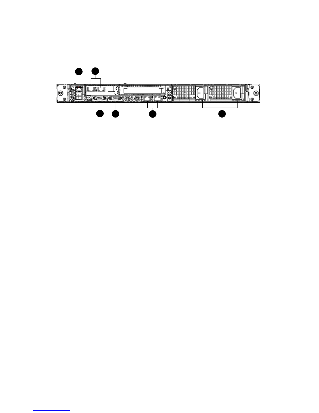
Figure 1 Cisco ACE XML appliance back panel
1
2
3
4
5
6
The back panel features highlighted in the figure are:
1. iLO 2 NIC
2. NIC 3 (eth0) and NIC 4 (eth1)
3. Serial connector
4. Video connector
5. Integrated NIC 1 (eth2) and NIC 2 (eth3)
6. Power supply bays 1 and 2
Notice that there are five NIC connectors on the back panel. However, the NIC connector shown in
callout 1 is intended for Integrated Lights-Out 2 (iLO 2) connectivity only, and not service traffic. The
iLO module can be used for certain maintenance tasks, such as remotely starting and stopping the
appliance. For more information on using the iLO module to access the appliance, contact your Cisco
ACE XML Gateway support representative.
The Cisco ACE XML Gateway appliance occupies one rack unit (1U). The dimensions of the appliance
are as follows:
• Height: 4.32 cm (1.70 in)
• Depth: 69.22 cm (27.25 in)
• Width: 42.62 cm (16.78 in)
For detailed information on installing the appliance in a rack, refer to the documentation provided by
the manufacturer of the rack hardware.
4 Performing the Initial Setup
The first step in using the Cisco ACE XML Gateway is installing the appliance on your network. To
do so, you need to configure a network interface on the appliance, along with some basic operating
settings for the appliance. When finished, you will be able to access the appliance shell interface using
a network-based client tool, such as PuTTY.
Page 4

4
Note This document provides an overview of the setup procedure. For complete information, se e
the Cisco ACE XML Gateway Installation and Administration Guide.
The initial configuration of the appliance is accomplished from its shell environment. The ACE XML
Gateway provides a menu-based shell interface that eases the task of setting the initial configuration
for the appliance.
To access the system shell, follow these steps:
Step 1 With the appliance turned off, connect an input device using one of these methods:
• By direct console connection. Use the video connectors on the front and back panels of
the appliance to connect a monitor to the applianc e. The back p anel contains keyboard
and mouse connectors, and the front panel has USB ports that can accept a USB mouse
and keyboard. Use any of these connectors to connect a monitor and keyboard or KVM
device to the appliance.
• By serial connection. To access the system shell by serial connection, connect a
workstation (laptop or desktop computer) by serial cable to the serial connector on the
back panel.
Step 2 If using a serial connection to the appliance, in the communications software on the attached
workstation, configure a connection with these settings:
• Bits per second: 9600
• Data bits: 8
• Parity: None
• Stop bits: 1
• Flow Control: None
The emulation mode for the connection should be VT100.
Step 3 Power up the appliance. The power button appears on the right side of the front panel. After
the appliance boots up, a login prompt appears.
Step 4 Log in using the default u sername and password (root/swo rdfish) or using a password
specifically provided to you. If using a se rial connectio n, establish th e connection with the
communication software.
If you used the default username and password to log in, you are prompted to enter a new password.
Follow the instructions on the screen to change your default password.
Page 5

5
When finished, the Main Menu appears. From there, you can perform the initial configuration of the
appliance. These tasks include configuring the network interface, specifying the operating mode of the
appliance, setting the system clock, and more. For instructions, see the Cisco ACE XML Gateway
Installation and Administrator’s Guide.
5 Product Documentation Set
The documentation set for the ACE XML Gateway product is made up of the following documents.
• ACE XML Gateway Installation and Administration Guide
Describes set up and configuration information applicable to the ACE XML Gateway product.
• ACE XML Gateway Getting Started Guide
Provides tutorial-style walkthroughs for setting up the Gateway policy to validate and process
service traffic. Using example services, it provides step-by-step instructions for setting up features
such as access control, validation, XML Encryption, XML Signature, and more .
• ACE XML Gateway User’s Guide
Includes detailed information on using the Manager web console to configure and manage the
ACE XML Gateway policy and monitor system activities.
• ACE XML Gateway Online Help
Contains reference-oriented information on the Manager web console interface.
All documents are available directly in the Manager web console e nvironment. While logg ed into th e
console, access the documents by clicking the help link at the top right side o f the co nsole page.
The documents are also available online at wwwcisco .com
6 Cisco 90-Day Limited Hardware Warranty Terms
There are special terms applicable to your hardware warranty and various services th at you can us e
during the warranty period. Your formal Warranty Statement, including the warranties and license
agreements applicable to Cisco software, is available on Cisco.com. F ollow these steps to ac cess and
download the Cisco Information Packet and your warranty and license agreements from Cisco.com.
1. Launch your browser, and go to this URL:
http://www.cisco.com/univercd/cc/td/doc/es_inpck/cetrans.htm
The Warranties and License Agreements page appe ars.
2. To read the Cisco Information Packet, follow these steps:
a. Click the Information Packet Num ber field, and make su re that the part number
78-5235-03C0 is highlighted.
Page 6

6
b. Select the language in which you would like to read the document.
c. Click Go.
The Cisco Limited W arranty and Software License page from the Information Packet appears.
d. Read the document online, or click the PDF icon to download and print the document in
Adobe Portable Document Format (PDF).
Note Y ou must have Adobe Acrobat Reader to view and print PDF files. Y ou can download
the reader from Adobe’s web site: http://www.adobe. com
3. To read translated and localized warranty information about your product, follow these steps:
a. Enter this part number in the Warranty Document Number field:
78-5236-01C0
b. Select the language in which you would like to read the document.
c. Click Go.
The Cisco warranty page appears.
d. Review the document online, or click the PDF icon to download and print the document in
Adobe Portable Document Format (PDF).
You can also contact the Cisco service and support web site for assistance:
http://www.cisco.com/public/Support_root.shtml.
Duration of Hardware Warranty
Ninety (90) days.
Replacement, Repair, or Refund Policy for Hardware
Cisco or its service center will use commercially reason able efforts to ship a replacement part within
ten (10) working days after receipt of a Return Materials Authorization (RMA) request. Actual
delivery times can vary, depending on the customer location.
Cisco reserves the right to refund the purchase price as its exclusive warranty remedy.
To Receive a Return Materials Authorization (RMA) Number
Contact the company from whom you purchased the product. If you purchased the product directly
from Cisco, contact your Cisco Sales and Service Representative.
Complete the information below, and keep it for reference:
Company product purchased from
Company telephone number
Page 7

7
7 Obtaining Documentation, Obtaining Support, and
Security Guidelines
For information on obtaining documentation, obtaining support, providing documentation feedback,
security guidelines, and also recommended aliases and general Cisco
documents, see the monthly
What’s
New in Cisco Product Documentation, which also lists all new and revised Cisco technical
documentation, at:
http://www.cisco.com/en/US/docs/general/whatsnew/whatsnew.html
Product model number
Product serial number
Maintenance contract number
Page 8

Americas Headquarters
Cisco Systems, Inc.
170 West Tasman Drive
San Jose, CA 95134-1706
USA
www.cisco.com
Tel: 408 526-4000
800 553-NETS (6387)
Fax: 408 527-0883
Asia Pacific Headquarters
Cisco Systems, Inc.
168 Robinson Road
#28-01 Capital Tower
Singapore 068912
www.cisco.com
Tel: +65 6317 7777
Fax: +65 6317 7799
Europe Headquarters
Cisco Systems International BV
Haarlerbergpark
Haarlerbergweg 13-19
1101 CH Amsterdam
The Netherlands
www-europe.cisco.com
Tel: 31 0 800 020 0791
Fax: 31 0 20 357 1100
Cisco has more than 200 offices worldwide. Addres ses, phone numbers, and fax numbers are listed on the
Cisco Website at www.cisco.com /go /o f fi c es .
© 2007 Cisco Systems, Inc. All rights reserved.
Printed in the USA on recycled paper containing 10% postconsumer waste.
78-18261-01
CCVP, the Cisco logo, and the Cisco Square Bridge logo are trademarks of Cisco Systems, Inc.; Changing the Way We Work, Live, Play, and Learn is a service mark of Cisco Systems,
Inc.; and Access Registrar, Aironet, BPX, Catalyst, CCDA, CCDP, CCIE, CCIP, CCNA, CCNP, CCSP, Cisco, the Cisco Certified Internetwork Expet logo, Cisco IOS, Cisco Press,
Cisco Systems, Cisco Systems Capital, the Cisco Systems logo, Cisco Unity, Enterprise/Solver, EtherChannel, EtherFast, EtherSwitch, Fast Step, Follow Me Browsing, FormShare,
GigaDrive, HomeLink, Internet Quotient, IOS, iPhone, IP/TV, iQ Expertise, the iQ logo, iQ Net Readiness Scorecard, iQuick Study, LightStream, Linksys, MeetingPlace, MGX,
Networking Academy, Network Registrar, Packet, PIX, ProConnect, ScriptShare, SMARTnet, StackWise, The Fastest Way to Increase Your Internet Quotient, and TransPath are
registered trademarks of Cisco Systems, Inc. and/or its affiliates in the United States and certain other countries.
All other trademarks mentioned in this document or Website are the property of their respective owners. The use of the word partner does not imply a partnership relationship
between Cisco and any other company. (0705R)
 Loading...