

Page 1

Compact Single Output EGC Amplifier
A93280
Installation and Operation Guide
Page 2
For Your Safety
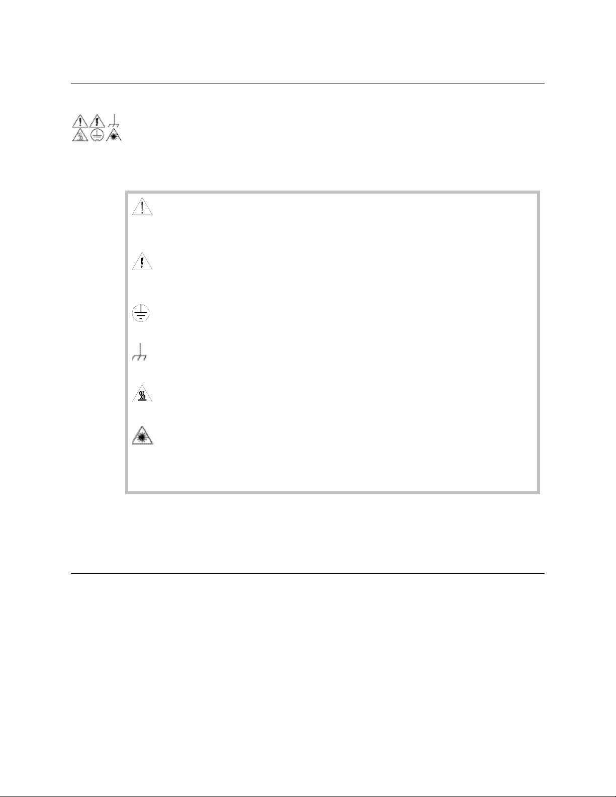
Avoid personal injury and product damage! Do not proceed beyond any symbol
until you fully understand the indicated conditions.
You may find this symbol in the document that accompanies this
product. This symbol indicates important operating or maintenance
instructions.
You may find this symbol affixed to the product. This symbol indicates a
live terminal where a dangerous voltage may be present; the tip of the
flash points to the terminal device.
You may find this symbol affixed to the product. This symbol indicates a
protective ground terminal.
You may find this symbol affixed to the product. This symbol indicates a
chassis terminal (normally used for equipotential bonding).
You may find this symbol affixed to the product. This symbol warns of a
potentially hot surface.
You may find this symbol affixed to the product and in this document.
This symbol indicates an infrared laser that transmits intensitymodulated light and emits invisible laser radiation or an LED that
transmits intensity-modulated light.
Explanation of Warning and Caution Icons
The following warning and caution icons alert you to important information about
the safe operation of this product:
Important
Please read this entire guide. If this guide provides installation or operation
instructions, give particular attention to all safety statements included in this guide.
Page 3

Notices
Trademark Acknowledgments
Cisco and the Cisco logo are trademarks or registered trademarks of Cisco and/or
its affiliates in the U.S. and other countries. A listing of Cisco's trademarks can be
found at www.cisco.com/go/trademarks.
Third party trademarks mentioned are the property of their respective owners.
The use of the word partner does not imply a partnership relationship between
Cisco and any other company. (1009R)
Publication Disclaimer
Cisco Systems, Inc. assumes no responsibility for errors or omissions that may
appear in this publication. We reserve the right to change this publication at any
time without notice. This document is not to be construed as conferring by
implication, estoppel, or otherwise any license or right under any copyright or
patent, whether or not the use of any information in this document employs an
invention claimed in any existing or later issued patent.
Copyright
© 2011 Cisco and/or its affiliates. All rights reserved.
Information in this publication is subject to change without notice. No part of this
publication may be reproduced or transmitted in any form, by photocopy, microfilm,
xerography, or any other means, or incorporated into any information retrieval
system, electronic or mechanical, for any purpose, without the express permission of
Cisco Systems, Inc.
Page 4

Contents
Important Safety Instructions .................................................................................................................... vi
Chapter 1 General Information
Overview ........................................................................................................................ 1-1
Overview Diagram ....................................................................................................... 1-2
Power Supply ................................................................................................................ 1-3
Plug-in Modules ............................................................................................................ 1-5
Power Saving Modes .................................................................................................... 1-6
Chapter 2 Installation
Overview ........................................................................................................................ 2-1
Tools and Accessories ................................................................................................... 2-2
Site Requirements ......................................................................................................... 2-3
Mounting the Amplifier ............................................................................................... 2-4
Chapter 3 Operation
Overview ........................................................................................................................ 3-1
Starting Up the Amplifier .......................................................................................... 3-2
Setting Up the Amplifier with a Computer ............................................................... 3-3
Setting Up the Amplifier with a Handheld Terminal .............................................. 3-8
ROSA Element Management System ....................................................................... 3-13
Setting Up Transponders ........................................................................................... 3-14
Starting Up the Amplifier with the AGC Module .................................................. 3-16
Setting Up the AGC Module ..................................................................................... 3-17
Functions of the AGC Module .................................................................................. 3-18
Temperature Back-off ................................................................................................. 3-20
Chapter 4 Customer Support Information
Overview ........................................................................................................................ 4-1
Support Telephone Numbers ...................................................................................... 4-2
4038501 Rev C iii
Page 5
Important Safety Instructions
Read and Retain Instructions
Carefully read all safety and operating instructions before operating this equipment, and
retain them for future reference.
Follow Instructions and Heed Warnings
Follow all operating and use instructions. Pay attention to all warnings and cautions in the
operating instructions, as well as those that are affixed to this equipment.
Terminology
The terms defined below are used in this document. The definitions given are based on those
found in safety standards.
Service Personnel - The term service personnel applies to trained and qualified individuals
who are allowed to install, replace, or service electrical equipment. The service personnel are
expected to use their experience and technical skills to avoid possible injury to themselves
and others due to hazards that exist in service and restricted access areas.
User and Operator - The terms user and operator apply to persons other than service
personnel.
Ground(ing) and Earth(ing) - The terms ground(ing) and earth(ing) are synonymous. This
document uses ground(ing) for clarity, but it can be interpreted as having the same meaning
as earth(ing).
Electric Shock Hazard
This equipment meets applicable safety standards.
WARNING!
To reduce risk of electric shock, perform only the instructions that are included in the
operating instructions. Refer all servicing to qualified service personnel only.
Electric shock can cause personal injury or even death. Avoid direct contact with dangerous
voltages at all times. The protective ground connection, where provided, is essential to safe
operation and must be verified before connecting the power supply.
Know the following safety warnings and guidelines:
Dangerous Voltages
Only qualified service personnel are allowed to perform equipment installation or
replacement.
Only qualified service personnel are allowed to remove chassis covers and access any of
the components inside the chassis.
Grounding
Do not violate the protective grounding by using an extension cable, power cable, or
autotransformer without a protective ground conductor.
Take care to maintain the protective grounding of this equipment during service or
repair and to re-establish the protective grounding before putting this equipment back
into operation.
Continued on next page
vi 4038501 Rev C
Page 6
Important Safety Instructions, Continued
Installation Site
When selecting the installation site, comply with the following:
Protective Ground - The protective ground lead of the building’s electrical installation
should comply with national and local requirements.
Environmental Condition – The installation site should be dry, clean, and ventilated. Do
not use this equipment where it could be at risk of contact with water. Ensure that this
equipment is operated in an environment that meets the requirements as stated in this
equipment’s technical specifications, which may be found on this equipment’s data sheet.
Installation Requirements
WARNING:
Allow only qualified service personnel to install this equipment. The installation must
conform to all local codes and regulations.
Equipment Placement
WARNING:
Avoid personal injury and damage to this equipment. An unstable mounting surface
may cause this equipment to fall.
To protect against equipment damage or injury to personnel, comply with the following:
Install this equipment in a restricted access location.
Do not install near any heat sources such as radiators, heat registers, stoves, or other
equipment (including amplifiers) that produce heat.
Place this equipment close enough to a mains AC outlet to accommodate the length of this
equipment’s power cord.
Route all power cords so that people cannot walk on, place objects on, or lean objects
against them. This may pinch or damage the power cords. Pay particular attention to
power cords at plugs, outlets, and the points where the power cords exit this equipment.
Use only with a cart, stand, tripod, bracket, or table specified by the manufacturer, or sold
with this equipment.
Make sure the mounting surface or rack is stable and can support the size and weight of
this equipment.
The mounting surface or rack should be appropriately anchored according to
manufacturer’s specifications. Ensure this equipment is securely fastened to the mounting
surface or rack where necessary to protect against damage due to any disturbance and
subsequent fall.
Ventilation
This equipment has openings for ventilation to protect it from overheating. To ensure
equipment reliability and safe operation, do not block or cover any of the ventilation
openings. Install the equipment in accordance with the manufacturer’s instructions.
Continued on next page
4038501 Rev C vii
Page 7
Important Safety Instructions, Continued
WARNING:
Avoid personal injury and damage to this equipment! Move any
equipment and cart combination with care. Quick stops, excessive
force, and uneven surfaces may cause this equipment and cart to
overturn.
Rack Mounting Safety Precautions
Mechanical Loading
Make sure that the rack is placed on a stable surface. If the rack has stabilizing devices, install
these stabilizing devices before mounting any equipment in the rack.
WARNING:
Avoid personal injury and damage to this equipment. Mounting this equipment in the
rack should be such that a hazardous condition is not caused due to uneven mechanical
loading.
Reduced Airflow
When mounting this equipment in the rack, do not obstruct the cooling airflow through the
rack. Be sure to mount the blanking plates to cover unused rack space. Additional
components such as combiners and net strips should be mounted at the back of the rack, so
that the free airflow is not restricted.
CAUTION:
Installation of this equipment in a rack should be such that the amount of airflow
required for safe operation of this equipment is not compromised.
Elevated Operating Ambient Temperature
Only install this equipment in a humidity- and temperature-controlled environment that
meets the requirements given in this equipment’s technical specifications.
CAUTION:
If installed in a closed or multi-unit rack assembly, the operating ambient temperature
of the rack environment may be greater than room ambient temperature. Therefore,
install this equipment in an environment compatible with the manufacturer’s maximum
rated ambient temperature.
Handling Precautions
When moving a cart that contains this equipment, check for any of the following possible
hazards:
Use caution when moving this equipment/cart combination to avoid injury from tip-over.
Continued on next page
viii 4038501 Rev C
Page 8

Important Safety Instructions, Continued
If the cart does not move easily, this condition may indicate obstructions or cables that may
need to be disconnected before moving this equipment to another location.
Avoid quick stops and starts when moving the cart.
Check for uneven floor surfaces such as cracks or cables and cords.
Grounding
This section provides instructions for verifying that the equipment is properly grounded.
Safety Plugs (USA Only)
This equipment is equipped with either a 3-terminal (grounding-type) safety plug or a 2terminal (polarized) safety plug. The wide blade or the third terminal is provided for safety.
Do not defeat the safety purpose of the grounding-type or polarized safety plug.
To properly ground this equipment, follow these safety guidelines:
Grounding-Type Plug - For a 3-terminal plug (one terminal on this plug is a protective
grounding pin), insert the plug into a grounded mains, 3-terminal outlet.
Note: This plug fits only one way. If this plug cannot be fully inserted into the outlet,
contact an electrician to replace the obsolete 3-terminal outlet.
Polarized Plug - For a 2-terminal plug (a polarized plug with one wide blade and one
narrow blade), insert the plug into a polarized mains, 2-terminal outlet in which one socket
is wider than the other.
Note: If this plug cannot be fully inserted into the outlet, try reversing the plug. If the plug
still fails to fit, contact an electrician to replace the obsolete 2-terminal outlet.
Grounding Terminal
If this equipment is equipped with an external grounding terminal, attach one end of an 18gauge wire (or larger) to the grounding terminal; then, attach the other end of the wire to a
ground, such as a grounded equipment rack.
Safety Plugs (European Union)
Class I Mains Powered Equipment – Provided with a 3-terminal AC inlet and requires
connection to a 3-terminal mains supply outlet via a 3-terminal power cord for proper
connection to the protective ground.
Note: The equipotential bonding terminal provided on some equipment is not designed to
function as a protective ground connection.
Class II Mains Powered Equipment – Provided with a 2-terminal AC inlet that may be
connected by a 2-terminal power cord to the mains supply outlet. No connection to the
protective ground is required as this class of equipment is provided with double or
reinforced and/or supplementary insulation in addition to the basic insulation provided in
Class I equipment.
Note: Class II equipment, which is subject to EN 50083-1, is provided with a chassis
mounted equipotential bonding terminal. See the section titled Equipotential Bonding for
connection instructions.
Continued on next page
4038501 Rev C ix
Page 9
Important Safety Instructions, Continued
Equipotential Bonding
If this equipment is equipped with an external chassis terminal marked with the IEC 60417-
5020 chassis icon ( ), the installer should refer to CENELEC standard EN 50083-1 or IEC
standard IEC 60728-11 for correct equipotential bonding connection instructions.
AC Power
Important: If this equipment is a Class I equipment, it must be grounded.
If this equipment plugs into an outlet, the outlet must be near this equipment, and must be
easily accessible.
Connect this equipment only to the power sources that are identified on the equipment-
rating label normally located close to the power inlet connector(s).
This equipment may have two power sources. Be sure to disconnect all power sources
before working on this equipment.
If this equipment does not have a main power switch, the power cord connector serves as
the disconnect device.
Always pull on the plug or the connector to disconnect a cable. Never pull on the cable
itself.
Unplug this equipment when unused for long periods of time.
Connection to –48 V DC/–60 V DC Power Sources
If this equipment is DC-powered, refer to the specific installation instructions in this manual
or in companion manuals in this series for information on connecting this equipment to
nominal -48 V DC/-60 V DC power sources.
Circuit Overload
Know the effects of circuit overloading before connecting this equipment to the power
supply.
CAUTION:
Consider the connection of this equipment to the supply circuit and the effect that
overloading of circuits might have on overcurrent protection and supply wiring. Refer
to the information on the equipment-rating label when addressing this concern.
General Servicing Precautions
WARNING:
Avoid electric shock! Opening or removing this equipment’s cover may expose you to
dangerous voltages.
Be aware of the following general precautions and guidelines:
Servicing - Refer all servicing to qualified service personnel. Servicing is required when
this equipment has been damaged in any way, such as power supply cord or plug is
damaged, liquid has been spilled or objects have fallen into this equipment, this equipment
has been exposed to rain or moisture, does not operate normally, or has been dropped.
Continued on next page
x 4038501 Rev C
Page 10

Important Safety Instructions, Continued
Wristwatch and Jewelry - For personal safety and to avoid damage of this equipment
during service and repair, do not wear electrically conducting objects such as a wristwatch
or jewelry.
Lightning - Do not work on this equipment, or connect or disconnect cables, during
periods of lightning.
Labels - Do not remove any warning labels. Replace damaged or illegible warning labels
with new ones.
Covers - Do not open the cover of this equipment and attempt service unless instructed to
do so in the instructions. Refer all servicing to qualified service personnel only.
Moisture - Do not allow moisture to enter this equipment.
Cleaning - Use a damp cloth for cleaning.
Safety Checks - After service, assemble this equipment and perform safety checks to
ensure it is safe to use before putting it back into operation.
Electrostatic Discharge
Electrostatic discharge (ESD) results from the static electricity buildup on the human body
and other objects. This static discharge can degrade components and cause failures.
Take the following precautions against electrostatic discharge:
Use an anti-static bench mat and a wrist strap or ankle strap designed to safely ground
ESD potentials through a resistive element.
Keep components in their anti-static packaging until installed.
Avoid touching electronic components when installing a module.
Fuse Replacement
To replace a fuse, comply with the following:
Disconnect the power before changing fuses.
Identify and clear the condition that caused the original fuse failure.
Always use a fuse of the correct type and rating. The correct type and rating are indicated
on this equipment.
Batteries
This product may contain batteries. Special instructions apply regarding the safe use and
disposal of batteries:
Safety
Insert batteries correctly. There may be a risk of explosion if the batteries are incorrectly
inserted.
Do not attempt to recharge ‘disposable’ or ‘non-reusable’ batteries.
Please follow instructions provided for charging ‘rechargeable’ batteries.
Replace batteries with the same or equivalent type recommended by manufacturer.
Do not expose batteries to temperatures above 100°C (212°F).
Continued on next page
4038501 Rev C xi
Page 11

Important Safety Instructions, Continued
Disposal
The batteries may contain substances that could be harmful to the environment
Recycle or dispose of batteries in accordance with the battery manufacturer’s instructions
and local/national disposal and recycling regulations.
The batteries may contain perchlorate, a known hazardous substance, so special handling
and disposal of this product might be necessary. For more information about perchlorate
and best management practices for perchlorate-containing substance, see
www.dtsc.ca.gov/hazardouswaste/perchlorate.
Electromagnetic Compatibility Regulatory Requirements
This equipment meets applicable electromagnetic compatibility (EMC) regulatory
requirements. EMC performance is dependent upon the use of correctly shielded cables of
good quality for all external connections, except the power source, when installing this
equipment.
Ensure compliance with cable/connector specifications and associated installation
instructions where given elsewhere in this manual.
Otherwise, comply with the following good practices:
Multi-conductor cables should be of single-braided, shielded type and have conductive
connector bodies and backshells with cable clamps that are conductively bonded to the
backshell and capable of making 360° connection to the cable shielding. Exceptions from
this general rule will be clearly stated in the connector description for the excepted
connector in question.
Ethernet cables should be of single-shielded or double-shielded type.
Coaxial cables should be of the double-braided shielded type.
EMC
Where this equipment is subject to USA FCC and/or Industry Canada rules, the following
statements apply:
FCC Statement for Class A Equipment
This equipment has been tested and found to comply with the limits for a Class A digital
device, pursuant to Part 15 of the FCC Rules. These limits are designed to provide
reasonable protection against harmful interference when this equipment is operated in a
commercial environment.
This equipment generates, uses, and can radiate radio frequency energy and, if not installed
and used in accordance with the instruction manual, may cause harmful interference to radio
communications. Operation of this equipment in a residential area is likely to cause harmful
interference in which case users will be required to correct the interference at their own
expense.
Continued on next page
xii 4038501 Rev C
Page 12

Important Safety Instructions, Continued
Industry Canada – Industrie Canadienne Statement
This apparatus complies with Canadian ICES-003.
Cet appareil est confome à la norme NMB-003 du Canada.
CENELEC/CISPR Statement with Respect to Class A Information Technology Equipment
This is a Class A equipment. In a domestic environment this equipment may cause radio
interference in which case the user may be required to take adequate measures.
Modifications
This equipment has been designed and tested to comply with applicable safety, laser safety,
and EMC regulations, codes, and standards to ensure safe operation in its intended
environment.
Do not make modifications to this equipment. Any changes or modifications could void the
user’s authority to operate this equipment.
Modifications have the potential to degrade the level of protection built into this equipment,
putting people and property at risk of injury or damage. Those persons making any
modifications expose themselves to the penalties arising from proven non-compliance with
regulatory requirements and to civil litigation for compensation in respect of consequential
damages or injury.
Accessories
Use only attachments or accessories specified by the manufacturer.
4038501 Rev C xiii
Page 13
About This Guide
Topic
See Page
Chapter 1: General Information
1-1
Chapter 2: Installation
2-1
Chapter 3: Operation
3-1
Chapter 4: Customer Information
4-1
Introduction
This guide describes how to operate, install, and configure the Compact Single
Output EGC Amplifier A93280.
Qualified Personnel
Only appropriately qualified and skilled personnel should attempt to install,
operate, maintain, and service this equipment.
WARNING:
Allow only qualified and skilled personnel to install, operate, maintain and
service this equipment. Otherwise, personal injury or equipment damage may
occur.
Who Should Read This Guide
This guide is intended for personnel who are responsible for installing, setting up,
monitoring, and maintaining this product.
Preface
In This Guide
This guide is divided into the following chapters.
xiiv Preface 4038501 Rev C
Page 14

Overview
Topic
See Page
Overview Diagram
1-2
Power Supply
1-3
Plug-in Modules
1-5
Power Saving Modes
1-6
Introduction
This chapter describes general information about the amplifier.
In This Chapter
This chapter contains the following topics.
Chapter 1
General Information
4038501 Rev C Introduction 1-1
Page 15

Overview Diagram
Overview Diagram
The following illustration is the block diagram of the amplifier.
1-2 Introduction 4038501 Rev C
Page 16

Power Supply
Power Supply
For Products Rated 100-240 VAC
When the amplifier is delivered with a 100-240 VAC power supply for mains supply,
the correct voltage is labeled on the side of the amplifier.
The amplifier has factory mounted mains cable and plugs, which according to
approval provisions may not be altered. The power unit is double insulated, and
supplies only this single amplifier.
Rating labels for 100-240 VAC power supply
Continued on next page
4038501 Rev C Introduction 1-3
Page 17

Power Supply, Continued
Fuse 5 AT, for 100 - 240 VAC
560852
Fuse 6.3 AT, for 24 - 65 VAC
1006647
Fuse 10A, for input/output port
4018230
For Products Rated 24-65 VAC
The amplifier is delivered with a 24-65 VAC power supply for remote supply. The
correct voltage is labeled on the side of the amplifier.
The amplifier can be supplied with 24-65 VAC via coaxial cables (max. 7A), or
directly to the AC input (max. 15A).
Rating label for 24-65 VAC power supply
CAUTION:
Permanently exceeding the maximum remote current draw may result in
damage to the amplifier.
Fuses
Note: All fuses must be replaced by a similar type.
1-4 Introduction 4038501 Rev C
Page 18

Plug-in Modules
Frequency split
Input
Output
42/54 MHz
4008154
4008155
65/87 MHz
589690
589691
Splitter
IN
OUT
OUT 1
OUT 2
A77041.10
3.5 dB
3.5 dB
3.5 dB
3.5 dB
A77042.10
6.0 dB
2.0 dB
2.0 dB
6.0 dB
A77043.10
10.5 dB
1.0 dB
1.0 dB
10.5 dB
A74069.10
N/A
N/A
0 dB
N/A
A74089.10
0 dB
N/A
N/A
0 dB
Modules
The amplifier is equipped with different plug-in locations for the input splitter,
diplex filter, equalizer, attenuator, and transponder.
Input Splitter/Output Splitter
Insert an input splitter, type A77041 through A77043. If an asymmetric splitter
(bridger) is used, the largest attenuation at the output (OUT) is obtained. If only a
signal at input (IN) is requested, jumper type A74089.10 should be used.
AUX Equalizer/Attenuator
Insert an equalizer or attenuator to adjust the amplifiers for impairments in the cable
network, if required. The equalizer type is A74100.10xxx, inverse equalizer type is
A74190.10xxx, and attenuator type is A77150.100xx. If no equalization /attenuation
is requested, 0 dB link, type A74069.10 should be used.
Diplex Filters
The following filters can be selected depending on the required frequency split.
AGC Module (optional)
AGC module 4031283 can be installed to monitor and control the output level of the
amplifier. The AGC module also provides downstream Auto Alignment, and has
three LEDs to indicate its status. For more information about installing the AGC
module, see Compact Automatic Gain Control Module for Compact EGC Amplifier
Mounting Instruction, part number 4036171. For more information about operating
the AGC module, see Chapter 3 of this document.
Reverse Equalizer
Place an equalizer, type A74141.1042 (42 MHz) or A74141.1065 (65 MHz) in the plugin slot for the reverse path equalizer, to select the desired reverse tilt frequency.
SMC Transponder (A91051) or HMS Transponder (A91067)
Use transponder, type A91051 or A91067, to monitor the amplifier output level,
temperature, power supply, etc., via the ROSA network management system.
4038501 Rev C Introduction 1-5
Page 19

Power Saving Modes
Conditions
Power reduction (W)
Power Saving On
2
Low Gain Mode
3
Power Saving
The amplifier provides two modes for reducing power consumption:
Power Saving On: When the amplifier is set to the power saving mode, the
power consumption will be reduced by approximately 2 W.
Low Gain Mode: In addition, when the forward gain of the amplifier is lower
than 32 dB, the amplifier will be set to the low gain mode, with an additional 3
W of power consumption reduced.
See the following table for power reductions of two power saving modes.
1-6 Introduction 4038501 Rev C
Page 20

Overview
Topic
See Page
Tools and Accessories
2-2
Site Requirements
2-3
Mounting the Amplifier
2-4
Introduction
This chapter describes the requirements and procedures for mounting the amplifier.
Qualified Personnel
Only appropriately qualified and skilled personnel should attempt to install,
operate, maintain, and service this equipment.
WARNING:
Allow only qualified and skilled personnel to install, operate, maintain and
service this equipment. Otherwise, personnel injury or equipment damage may
occur.
In This Chapter
This chapter contains the following topics.
Chapter 2
Installation
4038501 Rev C Installation 2-1
Page 21

Tools and Accessories
You need a…
To…
5 mm Allen wrench
Tighten the screws on the lid
3 mm flat-tip screwdriver
Clamp the inner conductor and PE conductor
M5 screws
Mount the amplifier
Ø 1.0 mm grounding wire
Connect Protective Earth (PE) to the PE terminal
Fastener
Torque Specification
Screw on the lid
Tighten from 6.5 Nm to 7 Nm (58 in-lb to 62 in-lb)
RF input/output port
connector
Tighten from 5 Nm to 6 Nm (44 in-lb to 53 in-lb)
PE terminal
Tighten from 2 Nm to 2.5 Nm (18 in-lb to 22 in-lb)
Required Tools and Hardware
Before you start the installation, make sure you have the following tools and
equipment to connect and configure the amplifier.
Torque Specifications
The following table provides the torque specifications.
2-2 Installation 4038501 Rev C
Page 22

Site Requirements
Introduction
Before you install the amplifier, make sure the installation site meets the
requirements discussed in this section.
Qualified Personnel
Only appropriately qualified and skilled personnel should attempt to install, operate,
maintain, and service this equipment.
WARNING:
Allow only qualified and skilled personnel to install, operate, maintain, and
service this equipment. Otherwise, personal injury or equipment damage may
occur.
Operating Temperature Requirements
The external operating temperature range is –40 to +55°C (–40 to +131°F). Before you
install, make sure the environment is within the range specified.
WARNING:
Avoid damage to the amplifier. Operating the amplifier above the maximum
operating temperature specified will result in damage to the product.
4038501 Rev C Installation 2-3
Page 23

Mounting the Amplifier
To Mount the Amplifier
The amplifier should be mounted vertically with the cable input underneath, to secure
the best possible operating temperature conditions. Use a 5 mm Allen wrench to
tighten the screws on the lid from 6.5 to 7 Nm (58 in-lb to 62 in-lb).
The following illustration shows the arrows that indicate the mounting bolt positions.
CAUTION!
Be aware of the size and weight of the amplifier when mounting. Ensure that
the mounting location has a stable flat surface, and can safely support the
amplifier’s maximum weight. Use the appropriate type of screws and
screwdrivers, depending on the mounting method.
To Open and Tighten the Housing
Use a 5 mm Allen wrench to tighten or loosen the closure bolts. To ensure a proper
seal, tighten or loosen the bolts in sequence 1, 2, 3, and 4 as shown in the following
diagram.
The pin length of the PG 11 cable connector at input and output is shown on the
cover plate of the amplifier. If needed, trim the connector with a wire cutter.
2-4 Installation 4038501 Rev C
Page 24

Overview
Topic
See Page
Starting Up the Amplifier
3-2
Setting Up the Amplifier with a Computer
3-3
Setting Up the Amplifier with a Handheld Terminal
3-8
ROSA Element Management System
3-13
Setting Up Transponders
3-14
Starting Up the Amplifier with the AGC Module
3-16
Setting Up the AGC Module
3-17
Functions of the AGC Module
3-18
Temperature Back-off
3-20
Introduction
This section describes the procedures for setting up and operating the amplifier.
The amplifier can be set up using a computer with an LCI software kit, or a
handheld terminal.
This product should be operated by qualified personnel only. Non-authorized
personnel are not allowed in the site area, otherwise physical injury or
equipment damage may occur.
In This Chapter
This chapter contains the following topics.
Chapter 3
Operation
WARNING:
4038501 Rev C Operation 3-1
Page 25

Starting Up the Amplifier
When the amplifier is powered up, the green LED on the power supply board
illuminates to indicate that the power is on, as illustrated below. In case the LED is
flashing, a short circuit may have occurred in the power supply.
3-2 Operation 4038501 Rev C
Page 26

Setting Up the Amplifier with a Computer
The amplifier can be set up using a computer with an LCI software kit, or a
handheld terminal.
Before setting up with a computer, ensure that the LCI software kit has been
installed on your computer. For detailed information about the software installation
and requirements, see LCI Software Installation Instructions, part number 4033113.
Operation
To set up the amplifier via the LCI software, you must connect the amplifier either to
a USB port with an LCI-USB cable or to a serial port. Follow the steps below to set up
the amplifier:
1. Start the LCI software.
Result: An LCI Detect Configuration window appears.
Note: If you use a serial port on the computer, type the desired serial port name into
the COM Port box such as COM1.
2. Click Node Products, and then Click Start to find the amplifier.
Result: A Refresh dialog box appears.
3. Click OK to finish.
4. Double-click the amplifier in the left tree to display the amplifier configuration
window.
Continued on next page
4038501 Rev C Operation 3-3
Page 27

Setting Up the Amplifier with a Computer, Continued
Result: A configuration window displays all settings of the amplifier, as
illustrated below.
Note: “AGC_Status” and “AGC_Configuration” categories are only available when
the AGC module is mounted. Otherwise, this column is blank.
5. Double-click the parameter you want to set up in the configuration window.
Result: A dialog box appears.
Continued on next page
3-4 Operation 4038501 Rev C
Page 28

Setting Up the Amplifier with a Computer, Continued
6. Either type a value in the text box, select the desired option button, or select the
desired value in the dialog box, as illustrated below.
7. Click Execute to validate the change.
Result: The change is effective right away.
Continued on next page
4038501 Rev C Operation 3-5
Page 29

Setting Up the Amplifier with a Computer, Continued
Category
Adjustable Item
Notes
Forward Path
Forward Gain
32 or 40 dB
Forward Output ATT
0 to 8 dB
Forward Output EQ
0 to 14 dB
Forward Input ATT
0 to 18 dB
Forward Input EQ
0 to 18 dB
Forward Power Saving
Off or On
Forward Bandwidth
862 MHz or 1 GHz
Reverse Path
Reverse Input ATT
0 to 20 dB
Reverse Interstage ATT
0 to 8 dB
Reverse Output ATT
0 to 18 dB
Reverse Output EQ
0 to 15 dB
Reverse Switch
0 dB, -6 dB, or Off
All parameters of the amplifier are listed in the window on page 3-4. The following
table lists the parameters that are configurable via the LCI software.
Continued on next page
3-6 Operation 4038501 Rev C
Page 30

Setting Up the Amplifier with a Computer, Continued
Category
Adjustable Item
Notes
AGC Configuration
AGC Mode Setting
Standby, AA, FixGain, or
AGC
High Pilot Frequency
47 to 1002 MHz
High Pilot Level
85 to 120 dBV
Backup High Pilot Frequency
47 to 1002 MHz
Backup High Pilot Level
85 to 120 dBV
Low Pilot Frequency
47 to 1002 MHz
Low Pilot Level
85 to 120 dBV
Backup Low Pilot Frequency
47 to 1002 MHz
Backup Low Pilot Level
85 to 120 dBV
Temperature Back Off
-20, -10, 0, 10, 20, 30, 40, 50,
60 or AUTO degC
Monitor Frequency 0
47 to 1002 MHz
Monitor Frequency 1
47 to 1002 MHz
Monitor Frequency 2
47 to 1002 MHz
Monitor Frequency 3
47 to 1002 MHz
Monitor Frequency 4
47 to 1002 MHz
Monitor Frequency 5
47 to 1002 MHz
Monitor Frequency 6
47 to 1002 MHz
Monitor Frequency 7
47 to 1002 MHz
Monitor Frequency 8
47 to 1002 MHz
Monitor Frequency 9
47 to 1002 MHz
The following table lists the parameters that are configurable when the AGC module
is mounted.
4038501 Rev C Operation 3-7
Page 31

Setting Up the Amplifier with a Handheld Terminal
Navigate to the submenus to open a menu for editing. The value can then be
changed. The button can also be used to reject a value entered by the keypad.
Navigate to the root menus to delete wrong digits when a menu is open for
editing. The button can also be used to reject a value entered by the keypad.
• 0
-
4 5 6
1 2 3
8 97
All numbers, „.‟ and „-„ are used to enter values. The numbers can also be used as
short cuts.
Navigate through menus at the same level to select the settings in some menus.
These buttons can also be used to fine-tune some values.
E
N
T
E
R
Confirm a setting or a change.
Keypads
The amplifier can be set up using a handheld terminal, type A91200.10. The
following table lists the terminal keypads and their definitions.
For detailed information, see Operation Instructions Handheld Programming
Terminal, type 91200, part number A541365.
Shortcuts
The menu item numbers can be used as shortcuts. To enter a menu, press the item
number. For example, if you want to enter the submenu “Reverse Mode” press
number keys 3 and 1 continuously. This key sequence displays the “Reverse Mode”
menu. See Menu Structures and Operations on page 3-8 to determine the number for a
required menu.
Ten shortcuts are specifically designed to help the user enter seven menus to set
parameters, indicated on the cover:
Press and hold “1” on the keypad to set forward input ATT directly.
Press and hold “2” on the keypad to set forward input EQ directly.
Press and hold “3” on the keypad to set forward output ATT directly.
Press and hold “4” on the keypad to set forward output EQ directly.
Press and hold “5” on the keypad to set reverse input ATT directly.
Press and hold “6” on the keypad to set reverse output EQ directly.
Press and hold “7” on the keypad to set reverse output ATT directly.
Continued on next page
3-8 Operation 4038501 Rev C
Page 32

Setting Up the Amplifier with a Handheld Terminal, Continued
Menus and Descriptions
1 General
Submenu1
Submenu2
Actions
11 Fwd Config
111 Fwd Gain
Read-write
Select 40 dB or 32 dB
112 Fwd Bandwidth
Read-write
Select 862 MHz or 1 GHz
12 Rev Config
121 Rev Gain
Read-write
20-28 dB, 0.5 dB step
13 Mounted Modules
131 Transponder
Read-only
Mounted or Not Mounted
132 AGC Module
Read-only
Mounted or Not Mounted
14 Power Supply
141 Remote Supply
Read-only
142 24 VDC
Read-only
143 12 VDC
Read-only
15 Temperature
–
Read-only
1°C step
2 Forward
Submenu1
Submenu2
Actions
21 Fwd Input Att
–
Read-write
Set Fwd input attenuation
0–18 dB, Unit in 0.1 dB, 0.5 dB step
22 Fwd Input EQ
–
Read-write
Set Fwd input EQ
0–18 dB, unit in 0.1 dB, 0.5 dB step
23 Fwd Output Att
–
Read-write
Set Fwd output attenuation
0–11.5 dB, unit in 0.1 dB, 0.5 dB step
24 Fwd Output EQ
–
Read-write
Set Fwd output EQ
0–14 dB, unit in 0.1 dB, 0.5 dB step
25 Power Saving
–
Read-write
Select ON or OFF
Menu Structures and Operations
The number before each menu name is the menu item number.
Continued on next page
4038501 Rev C Operation 3-9
Page 33

Setting Up the Amplifier with a Handheld Terminal, Continued
3 Reverse
Submenu1
Submenu2
Actions
31 Rev Input Att
–
Read-write
Set Rev input attenuation
0–20 dB, unit in 0.1 dB, 0.5 dB step
32 Rev Switch
–
Read-write
Set 0 dB, –6 dB or off
33 Rev Output
ATT
–
Read-write
Set Rev output attenuation
0–18 dB, unit in 0.1 dB, 0.5 dB step
34 Rev Output EQ
–
Read-write
Set Rev output EQ
0–15 dB, unit in 0.1 dB, 0.5 dB step
4 Copy Parameters
Submenu1
Submenu2
Actions
41 From Product
411 Setting 1
Nine amplifier settings can be
configured.
If a setting position is available, it
displays Empty; If not available, it
displays nothing.
Copy the parameters from one product
and store those parameters into a
handheld EEPROM. (Parameters for
both AGC module and Amplifier)
Select AMP, AMP+AGC, or Not Exist
(Abort or Execute)
412 Setting 2
413 Setting 3
414 Setting 4
415 Setting 5
416 Setting 6
417 Setting 7
418 Setting 8
419 Setting 9
42 To Product
421 Setting 1
Select and copy a setting to product.
If no valid setting exists, you cannot
enter the menu and No Data displays.
Restore the parameters from a
Handheld EEPROM to a product.
(Parameters for both AGC module and
Amplifier)
Select AMP, AMP+AGC, or Not Exist
(Abort or Execute)
422 Setting 2
423 Setting 3
424 Setting 4
425 Setting 5
426 Setting 6
427 Setting 7
428 Setting 8
429 Setting 9
43 Restore Default
–
Restore the default configuration to a
product. (Parameters for both AGC
module and amplifier)
Select Abort, AMP, AGC, or
AMP+AGC
Menu Structures and Operations, continued
3-10 Operation 4038501 Rev C
Continued on next page
Page 34

Setting Up the Amplifier with a Handheld Terminal, Continued
5 Identification
Submenu1
Submenu2
Actions
51 Model No
–
Read-only
Displays product model number
52 Serial No
–
Read-only
Displays product serial number
53 Time in Service
–
Read-only
Displays service time, Unit in days
54 Software ID
–
Read-only
Displays amplifier software ID
55 Terminal SW ID
–
Read-only
Displays handheld software ID
56 Product Date
–
Read-only
Displays product date of amplifier
57 HW Version
–
Read-only
Displays hardware version of
amplifier
6 TP Module
Submenu1
Submenu2
Actions
61 TP SW ID
–
Read-only (only when using HMS)
62 MAC ADDR
–
Read-only
63 IP ADDR
–
Read-write (only when using HMS)
Set IP address
64 MASTER RESET
–
Read-write
Select Abort or Reset
65 FREQ
651 STATUS
Read-only
652 FREQ SCAN
Read-write (only when using HMS)
Select Disable or Enable
653 BAUDRATE
Read-write (only when using SMC)
Select 9600, 19200, 38400 or ERROR
654 TX FREQ
Read-write
5–65 MHz, unit in 0.01 MHz
655 RX FREQ
Read-write
45–174 MHz, unit in 0.01 MHz
656 TX LEVEL
Read-write
24–50 dB, unit in 1 dB
657 RX LEVEL
Read-only (only when using HMS)
Note: This menu is only accessible when a transponder is mounted. Same with existing menu in
handheld through LCI interface on transponder.
Menu Structures and Operations, continued
4038501 Rev C Operation 3-11
Continued on next page
Page 35

Setting Up the Amplifier with a Handheld Terminal, Continued
7 AGC
Module
Submenu1
Submenu2
Actions
71 Pilot Settings
711 Pilot Hi Freq
Read-write
Pilot High Frequency, 47-1002 MHz, Unit in 0.0001
MHz
712 Pilot Hi Level
Read-write
Pilot High Level, 85-120 dBV, Unit in 0.1 dBV
713 Pilot Lo Freq
Read-write
Pilot Low Frequency, 47-1002 MHz, Unit in 0.0001
MHz
714 Pilot Lo Level
Read-write
Pilot Low Level, 85-120 dBV, Unit in 0.1 dBV
72 Bk Pilot
Settings
722 Bk PilotHi Freq
Read-write, Backup Pilot High Frequency, 47-1002
MHz, Unit in 0.0001 MHz
723 Bk PilotHi
Level
Read-write, Backup Pilot High Level, 85-120 dBV,
Unit in 0.1 dBV
725 BkPilot Lo Freq
Read-write, Backup Pilot Low Frequency, 47-1002
MHz, Unit in 0.0001 MHz
726 BkPilotLo Level
Read-write, Backup Pilot Low Level, 85-120 dBV,
Unit in 0.1 dBV
73 Temp Backoff
–
Read-write
-20 deg-C, -10 deg-C, 0 deg-C, 10 deg-C, 20 deg-C,
30 deg-C, 40 deg-C, 50 deg-C, 60 deg-C or AUTO
74 Function
–
Read-write
AA, AGC, FixGain, Standby, ! AA, ! AGC,
! FixGain or ! Standby
In case of alarms, flashing an exclamatory mark “!”
in “! AA/! AGC/! FGain/! Standby”
75 Alarm
–
Read-only
Normal, AA Time Out, AA OutRange, AGC
OutRange or PltLevOutRng
76 Pilot Display
761 Hi Pilot Slt
Read-only
Main/Backup
762 Lo Pilot Slt
Read-only
Main/Backup
763 Active Hi Freq
Read-only
Frequency unit in 0.0001 MHz
764 Active Hi Level
Read-only
Level unit in 0.1 dBV
765 Active Lo Freq
Read-only
Frequency unit in 0.0001 MHz
766 Active Lo Level
Read-only
Level unit in 0.1 dBV
77 Identification
771 Model Number
Read-only
Displays AGC model number
772 Serial Number
Read-only
Displays AGC serial number
773 Software ID
Read-only
Displays AGC software ID
Menu Structures and Operations, continued
3-12 Operation 4038501 Rev C
Page 36

ROSA Element Management System
ROSA Element Management System
To monitor the amplifier, a transponder must be installed in the amplifier. This
transponder will communicate back to the headend through the reverse path. The
transponder signal is received at the test point at output. See Overview Diagram on
page 1-2.
The level measured by the transponder will be attenuated by approximately 40 dB
relative to the output signal at output. The transponder transmitter level is adjusted
to the same level as the other reverse signals. The level from the transponder will be
attenuated by approximately 30 dB when injected at the reverse path.
Use a handheld terminal which contains the necessary driver for the unit to set up a
transponder. New drivers can be installed by means of downloading the kit
A91210.10.
4038501 Rev C Operation 3-13
Page 37

Setting Up Transponders
HMS Transponder
Use an HMS transponder to set up the parameters that are highlighted in the
following illustration.
Continued on next page
3-14 Operation 4038501 Rev C
Page 38

Setting Up Transponders, Continued
SMC Transponder
Use a SMC transponder to set up the parameters that are highlighted in the
following illustration.
CAUTION:
The SMC transponder can only be recognized by the amplifier when it is set to
IEP mode. To change the mode, connect a handheld, part number A91200.11 to
the LCI interface of the transponder. For detailed information, see Compact
Transponder 91051 Mounting Instructions, part number 744610. The USB – LCI
interface, part number A91220.10 can’t be used on the LCI port of the SMC
transponder.
4038501 Rev C Operation 3-15
Page 39

Starting Up the Amplifier with the AGC Module
LED Status
Description
Red
Warning: out of AGC range
Red, fast flashing
Warning: auto alignment is out of range
Red, slow flashing
Warning: auto alignment is timed out
Green
The AGC module is in AGC mode
Green, fast flashing
Auto alignment is in progress
Green, slow flashing
The AGC module is in Standby mode
Yellow
The AGC module is in Fixed Gain mode
Yellow, fast flashing
Level out of range is detected
Yellow, slow flashing
NA
All of the three LED
indicators are on
Communication with the amplifier failed
The following sections describe how to operate amplifiers with the AGC module
mounted. The LEDs on the AGC module indicate the status of the module when it is
mounted.
When the amplifier is powered up, and during initialization of the AGC module and
amplifier, the three LED indicators with different colors flash in sequence for
approximately 50 seconds. The AGC module reads the configurations, such as pilot
settings and AGC function settings, from the amplifier, and runs the configured
function. By default, the AGC module is set to Standby mode when the green LED
indicator is flashing slowly.
Before installing the AGC module, if the values of the output attenuator and
equalizer of the amplifier are less than 4 dB, these values will be set automatically to
4 dB after the AGC module is plugged in. On the other hand, if such values are not
less than 4 dB, they will be kept. These values are shown on the handheld display or
in the ROSA Element Management system.
Description of LED Indications
The following table lists LED status and description.
Note: To avoid the warnings of auto alignment being overlooked, the failure status
of auto alignment is not cleared unless the user manually changes the AGC module
to other functions or runs another auto alignment.
3-16 Operation 4038501 Rev C
Page 40

Setting Up the AGC Module
E
N
T
E
R
E
N
T
E
R
When the AGC module is plugged into the amplifier, it reads the settings, including
pilot settings and function settings from the amplifier, and starts to run the
configured function.
CAUTION:
When a SMC transponder will be installed, make sure its mode is set to IEP,
before configuring the AGC module. Refer to page 3-15 for details.
Setting Up the AGC Module with a Handheld Terminal
The following steps provide instructions on setting up the AGC module with a
handheld terminal. Before using the AGC module to monitor and control the output
signals of the amplifier, check the pilot settings to make sure they have been set to
the desired values.
1. Connect Terminal A91200 to the amplifier by plugging the connector of the
terminal into the LCI socket. The display on the terminal shows the status of the
AGC module.
2. Press to navigate to menu ”7 AGC Module” and press to open the
submenu. Go to “71 Pilot Settings” in the submenu by pressing again.
3. Press to enter the submenu “711 Pilot Hi Freq”, and press to
change the value of pilot high frequency. The menu title “711 Pilot Hi Freq” will
be flashing when the value can be changed. Use the number keys to enter the
desired value and press
to confirm.
4. Go to “712 Pilot Hi Level” and repeat step 3 to set up pilot high level.
5. Press to return to submenu “71 Pilot Settings” and repeat steps 3 and 4, to
set up pilot low frequency and level.
Note: Frequency and level have configurable ranges. See page 3-7 for details. Value
input out of the specified range will not be effective, and an “Out of Range” display
will appear.
6. Before using the auto alignment function, the cable temperature also has to be set
up. Go to submenu “73 Temp Backoff” and press and to select the
desired value. Press
to confirm. When the auto alignment is completed, the
temperature returns to 20℃ by default.
4038501 Rev C Operation 3-17
Page 41

Functions of the AGC Module
Standby
If no function is required, the AGC module is automatically set to Standby mode to
reduce power consumption. The standby mode is running in a cycle of 2 minutes
between monitoring and sleeping. In monitoring status, the AGC module detects the
levels of 4 pilots and the selected frequencies and sends the information back to the
handheld or the ROSA Element Management system. In sleeping status, the
microprocessor in AGC module continues communicating with the amplifier.
Auto Alignment
The auto alignment function adjusts input attenuator and equalizer to get the
desired output level and tilt, according to the pilot levels set up as per page 3-17.
When the auto alignment function is selected, if the differences between the detected
pilot levels and the set pilot levels are less then ±1 dB, the auto alignment function is
completed, and the AGC module goes back to Standby mode. Otherwise, the auto
alignment continues until one of the following occurs:
The differences are less than ±1 dB;
Auto alignment is timed out. After 2 minutes of auto alignment, a time-out
alarm is activated, either shown on the LED indicators, the handheld, or in the
ROSA Element Management system. See page 3-16 for the descriptions of LED
indicators. Meanwhile, the current input attenuator and equalizer values
remain, and the AGC module goes into Standby mode.
No input attenuator/equalizer can be adjusted. In this case, an alarm is
activated, either shown on the LED indicators, the handheld, or in the ROSA
Element Management system. See page 3-16 for the descriptions of LED
indicators. Meanwhile, the current input equalizer value remains, but the input
attenuator value is set to its maximum, and the AGC module goes into Standby
mode.
In the auto alignment function, when all the high or low pilots and their backup
pilots drop out, the current input equalizer value remains, while the input attenuator
value is set to its maximum, and the AGC module goes into Standby mode.
The user cannot switch the AGC module to other functions, or change the values of
attenuator or equalizer, until the auto alignment is completed. At this time, both
attenuator and equalizer values are updated in the handheld or ROSA Element
Management system. And if the AGC module is pulled out of the amplifier during
the auto alignment, the input attenuator and equalizer values are saved.
Note: Special attention is required when using the auto-alignment function. This
function is used for adjusting the input attenuator and equalizer only. Before
running the auto-alignment function to automatically set the input attenuator and
equalizer, make sure to manually set the interstage attenuator and equalizer to a
desired value first.
Continued on next page
3-18 Operation 4038501 Rev C
Page 42

Functions of the AGC Module, Continued
AGC
The AGC function continuously adjusts output attenuators and equalizers up to ±4
dB, to keep the output level and tilt of the amplifier constant. This function runs in a
cycle of 6 minutes to save power. During each AGC tuning session, the AGC module
monitors 4 pilot levels and 10 selected frequencies, and when the amplifier detects
that the adjusting values of attenuator and equalizer are out of the ±4 dB range, an
alarm activates on the LED indicators or ROSA Element Management system. See
page 3-16 for the descriptions of LED indicators. After each tuning task is completed,
the AGC module goes to sleep status for the rest of the cycle.
In AGC function, when all the high or low pilots and their backup pilots drop out,
the values of the output attenuator and equalizer are set back to those in effect before
the AGC function is performed. The AGC module stays in AGC mode, monitoring
the pilot levels and the 10 selected frequencies, in a cycle the same as in Standby
mode. However, the amplifier doesn‟t adjust the output attenuator and equalizer,
until the level of any of the 4 pilots goes back to its detected level range from 85 to
120 dBuV.
If the user switches the AGC function to Standby mode, or pulls the AGC module
out of the amplifier, the current values of output attenuator and equalizer remain. If
a new AGC module is installed into the amplifier, the values of output attenuator
and equalizer are set back to those in effect before the AGC function is performed,
and the AGC module continues with the AGC function.
Fixed Gain
The fixed gain function sets the amplifier to its nominal gain, and monitors the 4
pilot frequencies and the 10 selected frequencies, in a cycle the same as in Standby
mode.
4038501 Rev C Operation 3-19
Page 43

Temperature Back-off
Introduction
The temperature back-off feature is used to off-set the attenuator and equalizer when
the amplifier is auto aligned at a non-room temperature, to allow the AGC module
to work at room temperature. This feature is used for the auto alignment function
only, and is turned off when the auto alignment is completed.
Notes:
45 dB cable loss at 1 GHz is used to simulate the network variation over
temperature.
Room temperature is defined as 20℃.
Using the Temperature Back-off Feature
To use the temperature back-off feature, set up the desired value in submenu “731
Cable Temp” as per instructions on page 3-17.
There are two ways to determine the temperature compensation needed.
1. When the amplifier‟s ambient temperature is very different from the “network”
temperature, the user should enter the estimated “network” temperature
manually, by selecting from the available values in the submenu, including -20℃,
-10℃, 0℃, 10℃, 20℃, 30℃, 40℃, 50℃, and 60℃. If 20℃ is selected, the
temperature compensation function is turned off.
2. When the amplifier‟s ambient temperature is about the same as the “network”
temperature, the user can select AUTO in the submenu, and a sensor inside the
amplifier will measure the temperature and calculate the compensation
automatically.
3-20 Operation 4038501 Rev C
Page 44

Overview
IF…
THEN…
you have general questions about
this product
contact your distributor or sales agent for
product information or refer to product data
sheets on www.cisco.com.
you have technical questions about
this product
call the nearest Technical Service center.
you have customer service
questions about this product
call the nearest Customer Service center.
Topic
See Page
Support Telephone Numbers
4-2
Introduction
Chapter 4
Customer Support Information
This chapter contains information on obtaining product support.
Obtaining Product Support
In This Chapter
This chapter contains the following topics.
4038501 Rev C Customer Support Information 4-1
Page 45

Support Telephone Numbers
Region
Centers
Telephone and Fax Numbers
North America
Cisco Services
Atlanta, Georgia
United States
For Technical Support, call:
Toll-free: 1-800-722-2009
Local: 678-277-1120 (Press 2 at the prompt)
For Customer Service, call:
Toll-free: 1-800-722-2009
Local: 678-277-1120 (Press 3 at the prompt)
Fax: 770-236-5477
E-mail: customer-service@cisco.com
Europe,
Middle East,
Africa
Belgium
For Technical Support, call:
Telephone: 32-56-445-197 or 32-56-445-155
Fax: 32-56-445-061
For Customer Service, call:
Telephone: 32-56-445-444
Fax: 32-56-445-051
E-mail: service-elc@cisco.com
Japan
Japan
Telephone: 81-3-5908-2153 or +81-3-5908-2154
Fax: 81-3-5908-2155
Korea
Korea
Telephone: 82-2-3429-8800
Fax: 82-2-3452-9748
E-mail: songk@cisco.com
China (mainland)
China
Telephone: 86-21-2401-4433
Fax: 86-21-2401-4455
E-mail: repaircentercn@external.cisco.com
All other
Asia-Pacific countries
& Australia
Hong Kong
Telephone: 852-2588-4746
Fax: 852-2588-3139
E-mail: support.apr@sciatl.com
Brazil
Brazil
Telephone: 11-55-08-9999
Fax: 11-55-08-9998
E-mail: fattinl@cisco.com or ecavalhe@cisco.com
Mexico,
Central America,
Caribbean
Mexico
For Technical Support, call:
Telephone: 52-3515152599
Fax: 52-3515152599
For Customer Service, call:
Telephone: 52-55-50-81-8425
Fax: 52-55-52-61-0893
All other
Latin America
countries
Argentina
For Technical Support, call:
Telephone: 54-23-20-403340 ext 109
Fax: 54-23-20-403340 ext 103
For Customer Service, call:
Telephone: 770-236-5662
Fax: 770-236-5888
E-mail: keillov@cisco.com
Telephone Numbers
This table lists the Technical Support and Customer Service numbers for your area.
4-2 Customer Support Information 4038501 Rev C
Page 46

Cisco Systems, Inc.
5030 Sugarloaf Parkway, Box 465447
Lawrenceville, GA 30042
678 277-1120
800 722-2009
www.cisco.com
This document includes various trademarks of Cisco Systems, Inc. Please see the Notices section of
this document for a list of the Cisco Systems, Inc. trademarks used in this document.
Product and service availability are subject to change without notice.
© 2011 Cisco and/or its affiliates. All rights reserved.
February 2011
Part Number 4038501 Rev C
 Loading...