

Page 1

APPENDIX
A
Cisco Cabinet Dimensions
This appendix illustrates the space requirements for various system configurations in the Cisco
cabinet and a typical cable management setup. It also contains a table with the height of Cisco WAN
switching components in inches, centimeters, and rack-mount units (RMUs). This can help in the
calculation of height requirements for individual system configurations. The last illustration shows
the bracket installation in the Cisco cabinet (for a BPX 8620 node, in this case). The illustrated
components are the:
• BPX 8620
• IGX 8410, 8420, and 8430 switches
• Cisco MGX 8220 edge concentrator
The sequence of illustrations in this chapter is as follows:
• Cisco Cabinet
• Cable Management
• Examples of System Configurations
• Table of Component Heights
Cisco Cabinet Dimensions A-1
Page 2
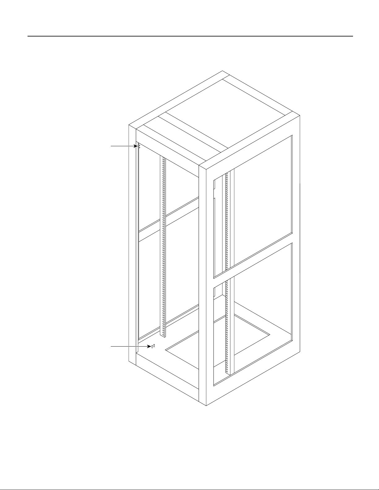
Figure A-1 Back View of Cisco Cabinet
Frame
bonding
connection
Frame
bonding
connection
A-2 BPX 8600 Series Installation
H8215
Page 3
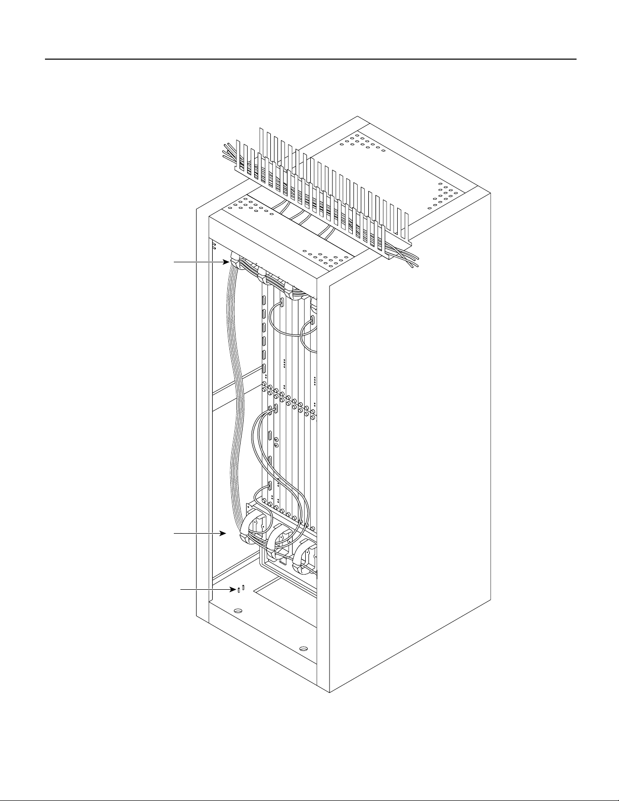
Figure A-2 Cable Management
Cable
manager
Cable
manager
Frame
bonding
connection
H7963
Cisco Cabinet Dimensions A-3
Page 4
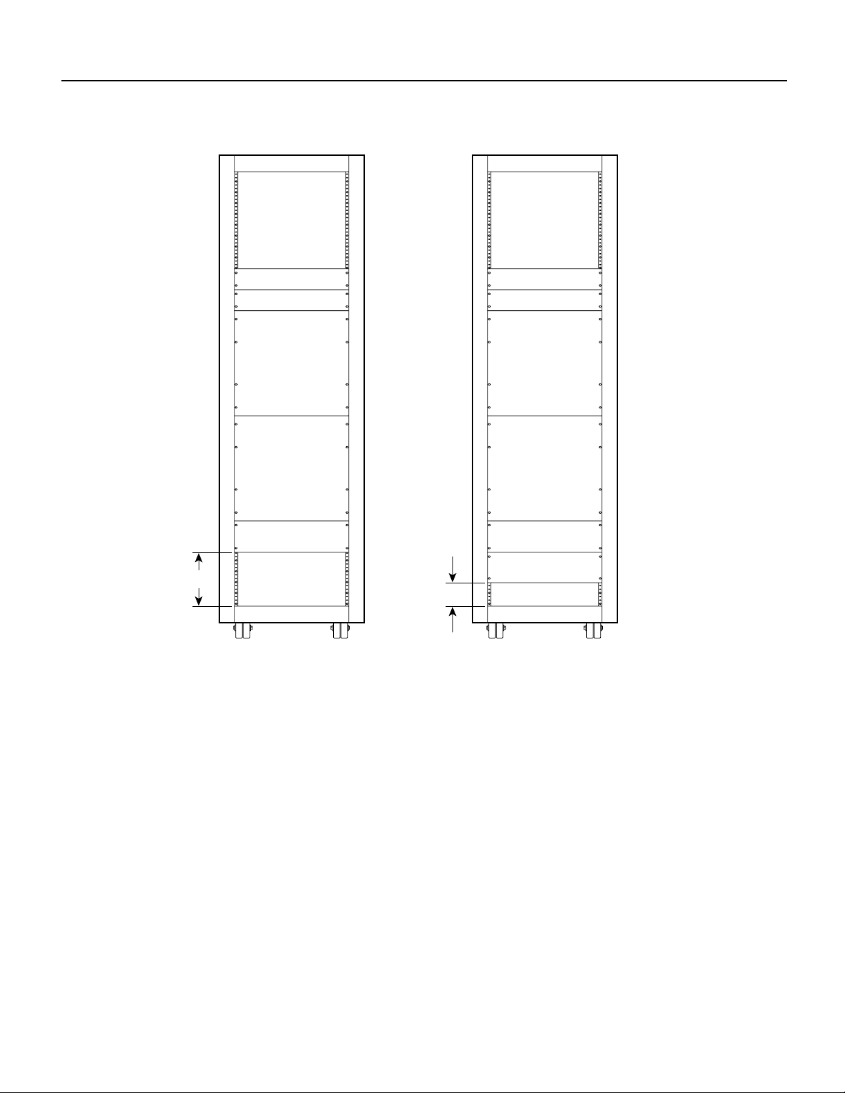
Figure A-3 IGX 8430 Switch, AC and DC-Powered
8.75
Exhaust plenum
Cooling unit
IGX switch
(upper shelf)
IGX switch
(lower shelf)
Cooling unit
DC-powered
IGX 8430 switch
Exhaust plenum
Cooling unit
IGX switch
(upper shelf)
IGX switch
(lower shelf)
Cooling unit
AC power supply
3.50
H8220
AC-powered
IGX 8430 switch
A-4 BPX 8600 Series Installation
Page 5
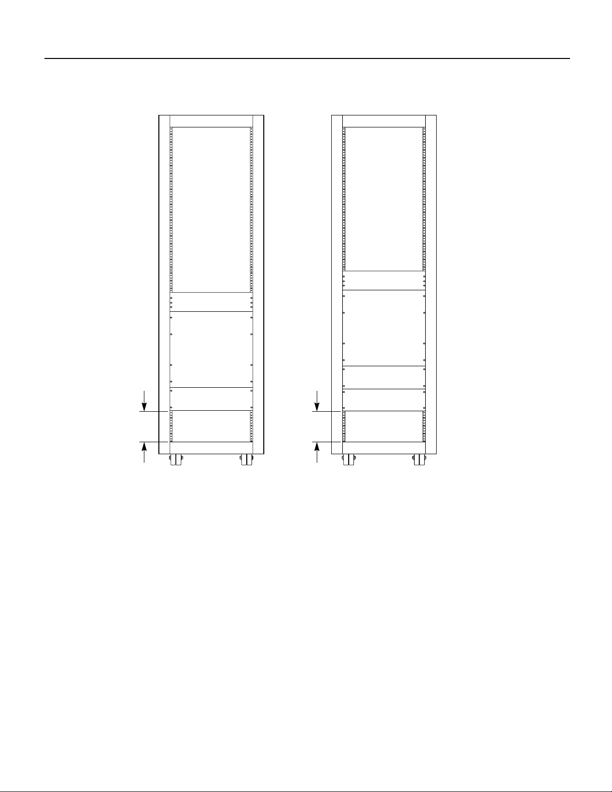
Figure A-4 IGX 8420 Swtch, DC-Powered and AC-Powered
Exhaust plenum
Exhaust plenum
IGX switch
IGX switch
Cooling unit
8.75
Cooling unit
DC-powered
IGX 8420 switch
AC power supply
8.75
H8364
AC-powered
IGX 8420 switch
Cisco Cabinet Dimensions A-5
Page 6

Figure A-5 IGX 8410 Switch, AC or DC-Powered
IGX 8410 switch
8.75
H8365
AC or DC-powered
IGX 8410 switch
A-6 BPX 8600 Series Installation
Page 7

Figure A-6 Single BPX Switch, AC and DC-Powered
BPX 8620 switch BPX 8620 switch
8.75
3.50
DC-powered BPX 8620 node AC-powered BPX 8620 node
AC power supply
H8217
Cisco Cabinet Dimensions A-7
Page 8

Figure A-7 Single BPX Node and MGX 8220 Edge Concentrator, AC and DC-Powered
Exhaust plenum
8.75
Exhaust plenum
MGX 8220
Cooling unit
BPX 8620 switch BPX 8620 switch
3.50
DC-powered BPX 8620
and MGX 8220 units
MGX 8220
Cooling unit
AC power supply
AC power supply
AC-powered BPX 8620
and MGX 8220 units
H8218
A-8 BPX 8600 Series Installation
Page 9

Figure A-8 BPX Node, MGX 8220 Edge Concentrator, and ESP, AC and DC-Powered
Exhaust plenum
Exhaust plenum
MGX 8220
Cooling unit
BPX 8620 switch BPX 8620 switch
8.75
WAN service node
BPX 8620/MGX 8220/ESP
DC power
MGX 8220
Cooling unit
AC power supply
AC power supply
3.50
H8219
WAN service node
BPX 8620/MGX 8220/ESP
AC power
Cisco Cabinet Dimensions A-9
Page 10

Figure A-9 BPX Node With 2 ESP Systems and 3 MGX 8220 Shelves, DC-Powered
Exhaust plenum
MGX 8220
MGX 8220 booster
MGX 8220
MGX 8220
Cooling unit
ESP
ESP
BPX 8620
WAN Service Node
BPX 8620/MGX 8220/ESP
DC power
H8221
A-10 BPX 8600 Series Installation
Page 11

Figure A-10 Six MGX 8220 Edge Concentrators, DC-Powered
Exhaust plenum
MGX 8220
MGX 8220
MGX 8220 booster
MGX 8220
MGX 8220
MGX 8220 booster
MGX 8220
MGX 8220
Cooling unit
3.50
Six MGX 8220 edge concentrators
H8222
Cisco Cabinet Dimensions A-11
Page 12

Figure A-11 BPX Node With Three MGX 8220 Edge Concentrators, DC-Powered
Exhaust plenum
MGX 8220
Concentrator
MGX 8220 booster
MGX 8220
Concentrator
MGX 8220
Concentrator
Cooling unit
BPX 8620 switch
3.50
H8223
One BPX 8620 and
three MGX 8220 units
A-12 BPX 8600 Series Installation
Page 13

Table A-1 Table of Cisco Cabinet and Component Heights
Components Unit Height
Inches CM RMUs
MGX 8220 Card Cage 8.75 22.225 5
MGX 8220 AC Power Supply shelf 5.25 13.335 3
MGX 8220 Booster Fan Assembly 3.5 8.89 2
MGX 8220 Cooling Assembly 5.25 13.335 3
MGX 8220 Exhaust Plenum 3.5 8.89 2
BPX AC Power Supply shelf 5.25 13.335 3
BPX Card Cage 22.75 57.785 13
IGX AC Power Supply shelf 5.25 13.335 3
IGX Booster Fan Assembly 3.5 8.89 2
IGX Card Cage 17.5 44.45 10
IGX Cooling Assembly 5.25 13.335 3
IGX Exhaust Plenum 3.5 8.89 2
IGX Node 24.5 62.23 14
VNS 5.25 13.335 3
Unit Height
Cabinet
Cisco Cabinet 71.75 1822.45 41
Other Cabinets 75.25 1911.35 43
Inches CM RMUs
Note The depth of the Cisco-supplied cabinet is 36 inches, the width is 23 inches, and the weight
(empty of equipment with side panels installed) is 233 pounds.
Cisco Cabinet Dimensions A-13
Page 14

Figure A-12 Mounting Brackets (BPX Example)
BPX shelf
Rear rail
Bottom of
support bracket
is mounted even
with bottom of
BPX shelf
Front
rail
19.86 Ref
Additional
bracket for
AC power
supply
H8205
A-14 BPX 8600 Series Installation
 Loading...