

Page 1

Cisco 850 Series and Cisco 870 Series
Access Routers Software
Configuration
Corporate Headquarters
Cisco Systems, Inc.
170 West Tasman Drive
San Jose, CA 95134-1706
USA
http://www.cisco.com
Tel: 408 526-4000
800 553-NETS (6387)
Fax: 408 526-4100
Text Part Number: OL-5332-01
Guide
Page 2

THE SPECIFICATIONS AND INFORMATION REGARDING THE PRODUCTS IN THIS MANUAL ARE SUBJECT TO CHANGE WITHOUT NOTICE. ALL
STATEMENTS, INFORMATION, AND RECOMMENDATIONS IN THIS MANUAL ARE BELIEVED TO BE ACCURATE BUT ARE PRESENTED WITHOUT
WARRANTY OF ANY KIND, EXPRESS OR IMPLIED. USERS MUST TAKE FULL RESPONSIBILITY FOR THEIR APPLICATION OF ANY PRODUCTS.
THE SOFTWARE LICENSE AND LIMITED WARRANTY FOR THE ACCOMPANYING PRODUCT ARE SET FORTH IN THE INFORMATION PACKET THAT
SHIPPED WITH THE PRODUCT AND ARE INCORPORATED HEREIN BY THIS REFERENCE. IF YOU ARE UNABLE TO LOCATE THE SOFTWARE LICENSE
OR LIMITED WARRANTY, CONTACT YOUR CISCO REPRESENTATIVE FOR A COPY.
The Cisco implementation of TCP header compression is an adaptation of a program developed by the University of California, Berkeley (UCB) as part of UCB’s public
domain version of the UNIX operating system. All rights reserved. Copyright © 1981, Regents of the University of California.
NOTWITHSTANDING ANY OTHER WARRANTY HEREIN, ALL DOCUMENT FILES AND SOFTWARE OF THESE SUPPLIERS ARE PROVIDED “AS IS” WITH
ALL FAULTS. CISCO AND THE ABOVE-NAMED SUPPLIERS DISCLAIM ALL WARRANTIES, EXPRESSED OR
LIMITATION, THOSE OF MERCHANTABILITY, FITNESS FOR A PARTICULAR PURPOSE AND NONINFRINGEMENT OR ARISING FROM A COURSE OF
DEALING, USAGE, OR TRADE PRACTICE.
IN NO EVENT SHALL CISCO OR ITS SUPPLIERS BE LIABLE FOR ANY INDIRECT, SPECIAL, CONSEQUENTIAL, OR INCIDENTAL DAMAGES, INCLUDING,
WITHOUT LIMITATION, LOST PROFITS OR LOSS OR DAMAGE TO DATA ARISING OUT OF THE USE OR INABILITY TO USE THIS MANUAL, EVEN IF CISCO
OR ITS SUPPLIERS HAVE BEEN ADVISED OF THE POSSIBILITY OF SUCH DAMAGES.
CCSP, the Cisco Square Bridge logo, Follow Me Browsing, and StackWise are trademarks of Cisco Systems, Inc.; Changing the Way We Work, Live, Play, and Learn, and iQuick
Study are service marks of Cisco Systems, Inc.; and Access Registrar, Aironet, ASIST, BPX, Catalyst, CCDA, CCDP, CCIE, CCIP, CCNA, CCNP, Cisco, the Cisco Certified
Internetwork Expert logo, Cisco IOS, Cisco Press, Cisco Systems, Cisco Systems Capital, the Cisco Systems logo, Cisco Unity, Empowering the Internet Generation,
Enterprise/Solver, EtherChannel, EtherFast, EtherSwitch, Fast Step, FormShare, GigaDrive, GigaStack, HomeLink, Internet Quotient, IOS, IP/TV, iQ Expertise, the iQ logo, iQ
Net Readiness Scorecard, LightStream, Linksys, MeetingPlace, MGX, the Networkers logo, Networking Academy, Network Registrar, Pack et , PIX, Post-Routing, Pre-Routing,
ProConnect, RateMUX, ScriptShare, SlideCast, SMARTnet, StrataView Plus, SwitchProbe, TeleRouter, The Fastest Way to Increase Your Internet Quotient, TransPath, and VCO
are registered trademarks of Cisco Systems, Inc. and/or its affiliates in the United States and certain other countries.
All other trademarks mentioned in this document or Website are the property of their respective owners. The use of the word partner does not imply a partnership relationship
between Cisco and any other company. (0501R)
IMPLIED, INCLUDING, WITHOUT
Cisco 850 Series and Cisco 870 Series Access Routers Software Configuration Guide
Copyright © 2005, Cisco Systems, Inc.
All rights reserved.
Page 3

Preface 11
PART
1 Getting Started
CONTENTS
Audience 11
Organization 12
Conventions 13
Notes, Cautions, and Timesavers 13
Command Conventions 13
Related Documents 14
Obtaining Documentation and Submitting a Service Request 14
CHAPTER
1 Basic Router Configuration 1
Interface Port Labels 1
Viewing the Default Configuration 2
Information Needed for Configuration 4
Configuring Basic Parameters 5
Configure Global Parameters 5
Configure Fast Ethernet LAN Interfaces 6
Configure WAN Interfaces 6
Configure the Fast Ethernet WAN Interface 6
Configure the ATM WAN Interface 7
Configure the Wireless Interface 7
Configuring a Loopback Interface 8
Configuration Example 8
Verifying Your Configuration 9
Configuring Command-Line Access to the Router 9
Configuration Example 11
Configuring Static Routes 11
Configuration Example 12
Verifying Your Configuration 12
OL-5332-01
Configuring Dynamic Routes 12
Configuring RIP 13
Configuration Example 14
Verifying Your Configuration 14
Cisco 850 Series and Cisco 870 Series Access Routers Software Configuration Guide
3
Page 4

Contents
Configuring Enhanced IGRP 14
Configuration Example 15
Verifying Your Configuration 15
PART
2 Configuring Your Router for Ethernet and DSL Access
CHAPTER
CHAPTER
CHAPTER
2 Sample Network Deployments 1
3 Configuring PPP over Ethernet with NAT 1
Configure the Virtual Private Dialup Network Group Number 2
Configure the Fast Ethernet WAN Interfaces 3
Configure the Dialer Interface 4
Configure Network Address Translation 6
Configuration Example 8
Verifying Your Configuration 9
4 Configuring PPP over ATM with NAT 1
Configure the Dialer Interface 3
Configure the ATM WAN Interface 5
Configure DSL Signaling Protocol 6
Configuring ADSL 6
Verify the Configuration 7
Configuring SHDSL 7
Verify the Configuration 8
CHAPTER
CHAPTER
4
Configure Network Address Translation 9
Configuration Example 11
Verifying Your Configuration 12
5 Configuring a LAN with DHCP and VLANs 1
Configure DHCP 2
Configuration Example 4
Verify Your DHCP Configuration 4
Configure VLANs 5
Assign a Switch Port to a VLAN 6
Verify Your VLAN Configuration 6
6 Configuring a VPN Using Easy VPN and an IPSec Tunnel 1
Configure the IKE Policy 4
Cisco 850 Series and Cisco 870 Series Access Routers Software Configuration Guide
OL-5332-01
Page 5

Configure Group Policy Information 5
Apply Mode Configuration to the Crypto Map 6
Enable Policy Lookup 6
Configure IPSec Transforms and Protocols 7
Configure the IPSec Crypto Method and Parameters 8
Apply the Crypto Map to the Physical Interface 9
Create an Easy VPN Remote Configuration 10
Verifying Your Easy VPN Configuration 11
Configuration Example 11
Contents
CHAPTER
CHAPTER
CHAPTER
7 Configuring VPNs Using an IPSec Tunnel and Generic Routing Encapsulation 1
Configure a VPN 2
Configure the IKE Policy 3
Configure Group Policy Information 4
Enable Policy Lookup 5
Configure IPSec Transforms and Protocols 5
Configure the IPSec Crypto Method and Parameters 6
Apply the Crypto Map to the Physical Interface 7
Configure a GRE Tunnel 8
Configuration Example 9
8 Configuring a Simple Firewall 1
Configure Access Lists 3
Configure Inspection Rules 3
Apply Access Lists and Inspection Rules to Interfaces 4
Configuration Example 5
9 Configuring a Wireless LAN Connection 1
Configure the Root Radio Station 2
Configure Bridging on VLANs 4
Configure Radio Station Subinterfaces 6
Configuration Example 7
CHAPTER
PART
OL-5332-01
10 Sample Configuration 1
3 Configuring Additional Features and Troubleshooting
Cisco 850 Series and Cisco 870 Series Access Routers Software Configuration Guide
5
Page 6

Contents
CHAPTER
CHAPTER
CHAPTER
11 Additional Configuration Options 1
12 Configuring Security Features 1
Authentication, Authorization, and Accounting 1
Configuring AutoSecure 2
Configuring Access Lists 2
Access Groups 3
Guidelines for Creating Access Groups 3
Configuring a CBAC Firewall 3
Configuring Cisco IOS Firewall IDS 4
Configuring VPNs 4
13 Configuring Dial Backup and Remote Management 1
Dial Backup Feature Activation Methods 1
Backup Interfaces 2
Configuring Backup Interfaces 2
Floating Static Routes 2
Configuring Floating Static Routes 3
Dialer Watch 4
Configuring Dialer Watch 4
CHAPTER
Dial Backup Feature Limitations 5
Configuration Example 6
Configuring Dial Backup and Remote Management Through the Console or Auxiliary Port 9
Configuration Tasks 10
Configuration Example 13
Configuring Dial Backup and Remote Management Through the ISDN S/T Port 16
Configuration Tasks 17
Configure ISDN Settings 17
Configure the Aggregator and ISDN Peer Router 20
14 Troubleshooting 1
Getting Started 1
Before Contacting Cisco or Your Reseller 1
ADSL Troubleshooting 2
SHDSL Troubleshooting 2
ATM Troubleshooting Commands 2
ping atm interface Command 3
Cisco 850 Series and Cisco 870 Series Access Routers Software Configuration Guide
6
OL-5332-01
Page 7

show interface Command 3
show atm interface Command 5
debug atm Commands 6
Guidelines for Using Debug Commands 6
debug atm errors Command 6
debug atm events Command 7
debug atm packet Command 8
Software Upgrade Methods 9
Recovering a Lost Password 9
Change the Configuration Register 10
Reset the Router 11
Reset the Password and Save Your Changes 12
Reset the Configuration Register Value 12
Managing Your Router with SDM 13
Contents
PART
4 Reference Information
APPENDIX
A Cisco IOS Software Basic Skills 1
Configuring the Router from a PC 1
Understanding Command Modes 2
Getting Help 4
Enable Secret Passwords and Enable Passwords 5
Entering Global Configuration Mode 5
Using Commands 6
Abbreviating Commands 6
Undoing Commands 6
Command-Line Error Messages 6
Saving Configuration Changes 7
Summary 7
Where to Go Next 7
APPENDIX
B Concepts 1
OL-5332-01
ADSL 1
SHDSL 2
Network Protocols 2
IP 2
Routing Protocol Options 2
Cisco 850 Series and Cisco 870 Series Access Routers Software Configuration Guide
7
Page 8

Contents
RIP 3
Enhanced IGRP 3
PPP Authentication Protocols 3
PAP 4
CHAP 4
TACACS+ 5
Network Interfaces 5
Ethernet 5
ATM for DSL 5
PVC 6
Dialer Interface 6
Dial Backup 6
Backup Interface 6
Floating Static Routes 7
Dialer Watch 7
APPENDIX
NAT 7
Easy IP (Phase 1) 8
Easy IP (Phase 2) 8
QoS 9
IP Precedence 9
PPP Fragmentation and Interleaving 9
CBWFQ 10
RSVP 10
Low Latency Queuing 10
Access Lists 11
C ROM Monitor 1
Entering the ROM Monitor 1
ROM Monitor Commands 2
Command Descriptions 3
Disaster Recovery with TFTP Download 3
TFTP Download Command Variables 4
Required Variables 4
Optional Variables 5
Using the TFTP Download Command 5
Configuration Register 6
Changing the Configuration Register Manually 6
Changing the Configuration Register Using Prompts 6
Cisco 850 Series and Cisco 870 Series Access Routers Software Configuration Guide
8
OL-5332-01
Page 9

Console Download 7
Command Description 8
Error Reporting 8
Debug Commands 8
Exiting the ROM Monitor 10
Contents
APPENDIX
I
NDEX
D Common Port Assignments 1
OL-5332-01
Cisco 850 Series and Cisco 870 Series Access Routers Software Configuration Guide
9
Page 10

Contents
10
Cisco 850 Series and Cisco 870 Series Access Routers Software Configuration Guide
OL-5332-01
Page 11

Preface
This software configuration guide provides instructions for using the Cisco command-line interface
(CLI) to configure features of the following Cisco
• Cisco 850 Series Routers
–
Cisco 851 Ethernet Access Router
–
Cisco 857 DSL Access Router
• Cisco 870 Series Routers
–
Cisco 871 Ethernet Access Router
–
Cisco 876, Cisco 877, and Cisco 878 DSL Access Routers
This preface describes the intended audience, the organization of this guide, and the text and command
conventions used throughout the guide. The preface includes the following topics:
• Audience
800 series routers:
Audience
Note We strongly recommend that network administrators with minimal familiarity with Cisco routers use the
• Organization
• Conventions
• Related Documents
• Obtaining Documentation and Submitting a Service Request
This guide is intended for network administrators whose backgrounds vary from having no or little
experience in configuring routers to having a high level of experience. You can use this guide in the
following situations:
• You have configured the software by using the Cisco Router Web Setup tool, and you want to
configure additional advanced software features by using the command-line interface (CLI).
• You want to configure the software using only the CLI.
Cisco Router and Security Device Manager (SDM)—a web-based configuration tool that allows you to
configure LAN and WAN interfaces, routing, Network Address Translation (NAT), firewalls, VPNs, and
other features on your router. To obtain the SDM release notes and other SDM documentation, go to
http://www.cisco.com/go/sdm and click the Technical Documentation link.
OL-5332-01
Cisco 850 Series and Cisco 870 Series Access Routers Software Configuration Guide
11
Page 12

Organization
See the “Organization” section of this preface to help you decide which chapters contain the information
you need to configure your router.
Organization
This guide contains the following information:
Part 1: Getting Started
• Chapter 1, “Basic Router Configuration”—Describes how to configure basic router features and
Part 2: Configuring Your Router for Ethernet and DSL Access
• Chapter 2, “Sample Network Deployments”—Provides a road map for Part 2.
• Chapter 3, “Configuring PPP over Ethernet with NAT”—Provides instructions on how to configure
• Chapter 4, “Configuring PPP over ATM with NAT”—Provides instructions on how to configure
• Chapter 5, “Configuring a LAN with DHCP and VLANs”—Provides instructions on how to
• Chapter 6, “Configuring a VPN Using Easy VPN and an IPSec Tunnel”—Provides instructions on
Preface
interfaces.
PPPoE with Network Address Translation (NAT) on your Cisco router.
PPPoA with Network Address Translation (NAT) on your Cisco router.
configure your Cisco router with multiple VLANs and to have it act as a DHCP server.
how to configure a virtual private network (VPN) with a secure IP tunnel using the Cisco Easy VPN.
• Chapter 7, “Configuring VPNs Using an IPSec Tunnel and Generic Routing
Encapsulation”—Provides instructions on how to configure a VPN with a secure IP tunnel and
generic routing encapsulation (GRE).
• Chapter 8, “Configuring a Simple Firewall”—Provides instructions on how to configure a basic
firewall on your Cisco router.
• Chapter 9, “Configuring a Wireless LAN Connection”—Provides instructions on how to configure
a wireless LAN connection on your Cisco router.
• Chapter 10, “Sample Configuration”—Presents a summary configuration example showing features
configured in the preceding chapters of this part of the guide.
Part 3: Configuring Additional Features and Troubleshooting
• Chapter 11, “Additional Configuration Options”—Provides a road map for Part 3.
• Chapter 12, “Configuring Security Features”—Explains basic configuration of Cisco IOS security
features, including firewall and VPN configuration.
• Chapter 13, “Configuring Dial Backup and Remote Management”—Provides instructions on how to
configure your Cisco router for dial backup and remote management.
• Chapter 14, “Troubleshooting”—Provides information on identifying and solving problems with the
ADSL line and the telephone interface. Also explains how to recover a lost software password.
Part 4: Reference Information
• Appendix A, “Cisco IOS Software Basic Skills”—Explains what you need to know about Cisco IOS
software before you begin to configure it.
• Appendix B, “Concepts”—Provides general concept explanations of features.
• Appendix C, “ROM Monitor”—Describes the use of the ROM Monitor (ROMMON) utility.
12
Cisco 850 Series and Cisco 870 Series Access Routers Software Configuration Guide
OL-5332-01
Page 13

Preface
• Appendix D, “Common Port Assignments”—Describes the currently assigned Transmission
Control Protocol (TCP) and User Datagram Protocol (UDP) port numbers.
• Index
Conventions
This guide uses the conventions described in the following sections for instructions and information.
Notes, Cautions, and Timesavers
Notes, cautions and time-saving tips use the following conventions and symbols:
Note Means reader take note. Notes contain helpful suggestions or references to materials not contained in
this guide.
Conventions
Caution This caution symbol means reader be careful. In this situation, you might do something that could result
in equipment damage or loss of data.
Timesaver This symbol means the described action saves time.
Command Conventions
Table 1 describes the command syntax used in this guide.
Ta b l e 1 Command Syntax Conventions
Convention Description
boldface Commands and keywords.
italic Command input that is supplied by you.
[ ] Optional keywords and default responses to system
{x | x | x} A choice of keywords (represented by x) appears in
^ or Ctrl Represents the key labeled Control. For example,
screen font
boldface screen
font
prompts appear within square brackets.
braces separated by vertical bars. You must select
one.
when you read ^D or Ctrl-D, you should hold down
the Control key while you press the D key.
Examples of information displayed on the screen.
Examples of information that you must enter.
OL-5332-01
Cisco 850 Series and Cisco 870 Series Access Routers Software Configuration Guide
13
Page 14

Related Documents
Related Documents
The following publications provide related information on these routers:
• Cisco 850 Series and Cisco 870 Series Access Routers Cabling and Setup Quick Start Guide
• Cisco 850 Series and Cisco 870 Series Access Routers Hardware Installation Guide
• Cisco Router and Security Device Manager (SDM) Quick Start Guide
• Cisco Access Router Wireless Configuration Guide
• Upgrading Memory in Cisco 800 Series Routers
• Regulatory Compliance and Safety Information for Cisco 800 Series and SOHO Series Routers
• Declarations of Conformity and Regulatory Information for Cisco Access Products with 802.11a/b/g
and 802.11b/g Radios
Obtaining Documentation and Submitting a Service Request
For information on obtaining documentation, submitting a service request, and gathering additional
information, see the monthly What’s
revised Cisco
technical documentation, at:
New in Cisco Product Documentation, which also lists all new and
Preface
http://www.cisco.com/en/US/docs/general/whatsnew/whatsnew.html
Subscribe to the What’s New in Cisco Product Documentation as a Really Simple Syndication (RSS) feed
and set content to be delivered directly to your desktop using a reader application. The RSS feeds are a free
service and Cisco currently supports RSS
Ve r si o n 2.0.
14
Cisco 850 Series and Cisco 870 Series Access Routers Software Configuration Guide
OL-5332-01
Page 15

P
ART
1
Getting Started
Page 16

Page 17

CHA P TER
1
Basic Router Configuration
This chapter provides procedures for configuring the basic parameters of your Cisco router, including
global parameter settings, routing protocols, interfaces, and command-line access. It also describes the
default configuration on startup.
Note Individual router models may not support every feature described throughout this guide. Features not
supported by a particular router are indicated whenever possible.
This chapter contains the following sections:
• Interface Port Labels
• Viewing the Default Configuration
• Information Needed for Configuration
• Configuring Basic Parameters
• Configuring Static Routes
• Configuring Dynamic Routes
• Configuring Enhanced IGRP
Each section includes a configuration example and verification steps, as available.
For complete information on how to access global configuration mode, see the “Entering Global
Configuration Mode” section in Appendix A, “Cisco IOS Basic Skills.” For more information on the
commands used in the following tables, see the Cisco IOS Release 12.3 documentation set.
Interface Port Labels
Table 1-1 lists the interfaces supported for each router and their associated port labels on the equipment.
Ta b l e 1-1 Supported Interfaces and Associated Port Labels by Cisco Router
Router Interface Port Label
Cisco 851 Fast Ethernet LAN LAN (top), FE0–FE3 (bottom)
OL-5332-01
Fast Ethernet WAN WAN (top), FE4 (bottom)
Wireless LAN (no label)
Cisco 850 Series and Cisco 870 Series Access Routers Software Configuration Guide
1-1
Page 18

Viewing the Default Configuration
Table 1-1 Supported Interfaces and Associated Port Labels by Cisco Router (continued)
Router Interface Port Label
Cisco 871 Fast Ethernet LAN FE0–FE3
Cisco 857 Fast Ethernet LAN LAN (top), FE0–FE3 (bottom)
Cisco 876 Fast Ethernet LAN LAN (top), FE0–FE3 (bottom)
Cisco 877 Fast Ethernet LAN LAN (top), FE0–FE3 (bottom)
Cisco 878 Fast Ethernet LAN FE0–FE3
Chapter 1 Basic Router Configuration
Fast Ethernet WAN FE4
Wireless LAN LEFT, RIGHT/PRIMARY
USB 1–0
ATM WA N ADSLoPOTS
Wireless LAN (no label)
ATM WA N ADSLoISDN
Wireless LAN LEFT, RIGHT/PRIMARY
BRI ISDN S/T
ATM WA N ADSLoPOTS
Wireless LAN LEFT, RIGHT/PRIMARY
ATM WA N G.SHDSL
Wireless LAN LEFT, RIGHT/PRIMARY
BRI ISDN S/T
Viewing the Default Configuration
When you first boot up your Cisco router, some basic configuration has already been performed. All of
the LAN and WAN interfaces have been created, console and VTY ports are configured, and the inside
interface for Network Address Translation has been assigned. Use the show
to view the initial configuration, as shown in
Example 1-1 Cisco 851 Default Configuration on Startup
Router# show running-config
Building configuration...
Current configuration : 1090 bytes
!
version 12.3
no service pad
service timestamps debug datetime msec
service timestamps log datetime msec
no service password-encryption
!
hostname Router
!
boot-start-marker
boot-end-marker
!
running-config command
Example 1-1.
1-2
Cisco 850 Series and Cisco 870 Series Access Routers Software Configuration Guide
OL-5332-01
Page 19

Chapter 1 Basic Router Configuration
no aaa new-model
ip subnet-zero
!
ip cef
ip ips po max-events 100
no ftp-server write-enable
!
interface FastEthernet0
no ip address
shutdown
!
interface FastEthernet1
no ip address
shutdown
!
interface FastEthernet2
no ip address
shutdown
!
interface FastEthernet3
no ip address
shutdown
!
interface FastEthernet4
no ip address
duplex auto
speed auto
!
interface Dot11Radio0
no ip address
shutdown
speed basic-1.0 basic-2.0 basic-5.5 6.0 9.0 basic-11.0 12.0 18.0 24.0 36.0 48.0
54.0
rts threshold 2312
station-role root
!
interface Vlan1
no ip address
!
ip classless
!
no ip http server
no ip http secure-server
!
control-plane
!
line con 0
no modem enable
transport preferred all
transport output all
line aux 0
transport preferred all
transport output all
line vty 0 4
login
transport preferred all
transport input all
transport output all
!
end
Viewing the Default Configuration
OL-5332-01
Cisco 850 Series and Cisco 870 Series Access Routers Software Configuration Guide
1-3
Page 20

Information Needed for Configuration
Information Needed for Configuration
You need to gather some or all of the following information, depending on your planned network
scenario, prior to configuring your network
• If you are setting up an Internet connection, gather the following information:
–
Point-to-Point Protocol (PPP) client name that is assigned as your login name
–
PPP authentication type: Challenge Handshake Authentication Protocol (CHAP) or Password
Authentication Protocol (PAP)
–
PPP password to access your Internet service provider (ISP) account
–
DNS server IP address and default gateways
• If you are setting up a connection to a corporate network, you and the network administrator must
generate and share the following information for the WAN interfaces of the routers:
–
PPP authentication type: CHAP or PAP
–
PPP client name to access the router
–
PPP password to access the router
• If you are setting up IP routing:
–
Generate the addressing scheme for your IP network.
Chapter 1 Basic Router Configuration
–
Determine the IP routing parameter information, including IP address, and ATM permanent
virtual circuits (PVCs). These PVC parameters are typically virtual path identifier (VPI), virtual
circuit identifier (VCI), and traffic shaping parameters.
–
Determine the number of PVCs that your service provider has given you, along with their VPIs
and VCIs.
–
For each PVC determine the type of AAL5 encapsulation supported. It can be one of the
following:
AAL5SNAP—This can be either routed RFC 1483 or bridged RFC 1483. For routed RFC 1483,
the service provider must provide you with a static IP address. For bridged RFC 1483, you may
use DHCP to obtain your IP address, or you may obtain a static IP address from your service
provider.
AAL5MUX PPP—With this type of encapsulation, you need to determine the PPP-related
configuration items.
• If you plan to connect over an ADSL or G.SHDSL line:
–
Order the appropriate line from your public telephone service provider.
For ADSL lines—Ensure that the ADSL signaling type is DMT (also called ANSI T1.413) or
DMT Issue 2.
For G.SHDSL lines—Verify that the G.SHDSL line conforms to the ITU G.991.2 standard and
supports Annex A (North America) or Annex B (Europe).
Once you have collected the appropriate information, you can perform a full configuration on
your router, beginning with the tasks in the
“Configuring Basic Parameters” section.
1-4
Cisco 850 Series and Cisco 870 Series Access Routers Software Configuration Guide
OL-5332-01
Page 21

Chapter 1 Basic Router Configuration
Configuring Basic Parameters
To configure the router, perform one or more of these tasks:
• Configure Global Parameters
• Configure Fast Ethernet LAN Interfaces
• Configure WAN Interfaces
• Configuring a Loopback Interface
• Configuring Command-Line Access to the Router
A configuration example is presented with each task to show the network configuration following
completion of that task.
Configure Global Parameters
Perform these steps to configure selected global parameters for your router:
Configuring Basic Parameters
Step 1
Step 2
Step 3
Step 4
Command Purpose
configure terminal
Enters global configuration mode, when using the
console port.
Example:
Router> enable
Router# configure terminal
Router(config)#
hostname name
Example:
Router(config)# hostname Router
Router(config)#
enable secret password
If you are connecting to the router using a remote
terminal, use the following:
telnet router name or address
Login: login id
Password: *********
Router> enable
Specifies the name for the router.
Specifies an encrypted password to prevent
unauthorized access to the router.
Example:
Router(config)# enable secret cr1ny5ho
Router(config)#
no ip domain-lookup
Disables the router from translating unfamiliar
words (typos) into IP addresses.
Example:
Router(config)# no ip domain-lookup
Router(config)#
OL-5332-01
For complete information on the global parameter commands, see the Cisco IOS Release 12.3
documentation set.
Cisco 850 Series and Cisco 870 Series Access Routers Software Configuration Guide
1-5
Page 22

Configuring Basic Parameters
Configure Fast Ethernet LAN Interfaces
The Fast Ethernet LAN interfaces on your router are automatically configured as part of the default
VLAN and as such, they are not configured with individual addresses. Access is afforded through the
VLAN. You may assign the interfaces to other VLANs if desired. For more information about creating
VLANs, see
Chapter 5, “Configuring a LAN with DHCP and VLANs.”
Configure WAN Interfaces
The Cisco 851 and Cisco 871 routers each have one Fast Ethernet interface for WAN connection. The
857, Cisco 877, and Cisco 878 routers each have one ATM interface for WAN connection.
Cisco
Based on the router model you have, configure the WAN interface(s) using one of the following
procedures:
• Configure the Fast Ethernet WAN Interface
• Configure the ATM WAN Interface
Chapter 1 Basic Router Configuration
Configure the Fast Ethernet WAN Interface
This procedure applies only to the Cisco 851 and Cisco 871 router models. Perform these steps to
configure the Fast Ethernet interface, beginning in global configuration mode:
Command Purpose
Step 1
Step 2
Step 3
interface type number
Example:
Router(config)# interface fastethernet 4
Router(config-int)#
ip address ip-address mask
Example:
Router(config-int)# ip address 192.168.12.2
255.255.255.0
Router(config-int)#
no shutdown
Example:
Router(config-int)# no shutdown
Router(config-int)#
Enters the configuration mode for a Fast
Ethernet WAN interface on the router.
Sets the IP address and subnet mask for the
specified Fast Ethernet interface.
Enables the Ethernet interface, changing its
state from administratively down to
administratively up.
1-6
Step 4
Cisco 850 Series and Cisco 870 Series Access Routers Software Configuration Guide
exit
Example:
Router(config-int)# exit
Router(config)#
Exits configuration mode for the Fast Ethernet
interface and returns to global configuration
mode.
OL-5332-01
Page 23

Chapter 1 Basic Router Configuration
Configure the ATM WAN Interface
This procedure applies only to the Cisco 857, Cisco 876, Cisco 877 and Cisco 878 models.
Perform these steps to configure the ATM interface, beginning in global configuration mode:
Command Purpose
Step 1
For the Cisco 878 model only:
controller dsl 0
mode atm
exit
Example:
Router(config)# controller dsl 0
Router(config-controller)# mode atm
Router(config-controller)# exit
Router(config)#
Configuring Basic Parameters
For routers using the G.SHDSL signaling, perform
these commands. Ignore this step for routers using
ADSL signaling.
Step 2
Step 3
Step 4
Step 5
interface type number
Example:
Router(config)# interface atm0
Router(config-int)#
ip address ip-address mask
Example:
Router(config-int)# ip address 10.10.10.100
255.255.255.0
Router(config-int)#
no shutdown
Example:
Router(config-int)# no shutdown
Router(config-int)#
exit
Example:
Router(config-int)# exit
Router(config)#
Identifies and enters the configuration mode for an
ATM interface.
Sets the IP address and subnet mask for the ATM
interface.
Enables the ATM 0 interface.
Exits configuration mode for the ATM interface
and returns to global configuration mode.
Configure the Wireless Interface
The wireless interface enables connection to the router through a wireless LAN connection. For more
information about configuring a wireless connection, see
Connection,” and the Cisco Access Router Wireless Configuration Guide.
Cisco 850 Series and Cisco 870 Series Access Routers Software Configuration Guide
OL-5332-01
Chapter 9, “Configuring a Wireless LAN
1-7
Page 24

Configuring Basic Parameters
Configuring a Loopback Interface
The loopback interface acts as a placeholder for the static IP address and provides default routing
information.
For complete information on the loopback commands, see the Cisco IOS Release 12.3
set.
Step 1
documentation
Perform these steps to configure a loopback interface:
Command Purpose
interface type number
Example:
Router(config)# interface Loopback 0
Router(config-int)#
Chapter 1 Basic Router Configuration
Enters configuration mode for the loopback
interface.
Step 2
ip address ip-address mask
Example:
Router(config-int)# ip address 10.108.1.1
255.255.255.0
Router(config-int)#
Step 3
exit
Example:
Router(config-int)# exit
Router(config)#
Configuration Example
The loopback interface in this sample configuration is used to support Network Address Translation
(NAT) on the virtual-template interface. This configuration example shows the loopback interface
configured on the Fast Ethernet interface with an IP address of 10.10.10.100/24, which acts as a static
IP address. The loopback interface points back to virtual-template1, which has a negotiated IP address.
!
interface loopback 0
ip address 10.10.10.100 255.255.255.0 (static IP address)
ip nat outside
!
interface Virtual-Template1
ip unnumbered loopback0
no ip directed-broadcast
ip nat outside
!
Sets the IP address and subnet mask for the
loopback interface.
Exits configuration mode for the loopback
interface and returns to global configuration
mode.
1-8
Cisco 850 Series and Cisco 870 Series Access Routers Software Configuration Guide
OL-5332-01
Page 25

Chapter 1 Basic Router Configuration
Verifying Your Configuration
To verify that you have properly configured the loopback interface, enter the show interface loopback
command. You should see verification output similar to the following example.
Router# show interface loopback 0
Loopback0 is up, line protocol is up
Hardware is Loopback
Internet address is 10.10.10.100/24
MTU 1514 bytes, BW 8000000 Kbit, DLY 5000 usec,
reliability 255/255, txload 1/255, rxload 1/255
Encapsulation LOOPBACK, loopback not set
Last input never, output never, output hang never
Last clearing of "show interface" counters never
Queueing strategy: fifo
Output queue 0/0, 0 drops; input queue 0/75, 0 drops
5 minute input rate 0 bits/sec, 0 packets/sec
5 minute output rate 0 bits/sec, 0 packets/sec
0 packets input, 0 bytes, 0 no buffer
Received 0 broadcasts, 0 runts, 0 giants, 0 throttles
0 input errors, 0 CRC, 0 frame, 0 overrun, 0 ignored, 0 abort
0 packets output, 0 bytes, 0 underruns
0 output errors, 0 collisions, 0 interface resets
0 output buffer failures, 0 output buffers swapped out
Configuring Basic Parameters
Another way to verify the loopback interface is to ping it:
Router# ping 10.10.10.100
Type escape sequence to abort.
Sending 5, 100-byte ICMP Echos to 10.10.10.100, timeout is 2 seconds:
!!!!!
Success rate is 100 percent (5/5), round-trip min/avg/max = 1/2/4 ms
Configuring Command-Line Access to the Router
Perform these steps to configure parameters to control access to the router, beginning in global
configuration mode.
Command Purpose
Step 1
Step 2
line [aux | console | tty | vty] line-number
Example:
Router(config)# line console 0
Router(config)#
password password
Example:
Router(config)# password 5dr4Hepw3
Router(config)#
Enters line configuration mode, and specifies the
type of line.
This example specifies a console terminal for
access.
Specifies a unique password for the console
terminal line.
OL-5332-01
Cisco 850 Series and Cisco 870 Series Access Routers Software Configuration Guide
1-9
Page 26

Configuring Basic Parameters
Command Purpose
Step 3
login
Example:
Router(config)# login
Router(config)#
Chapter 1 Basic Router Configuration
Enables password checking at terminal session
login.
Step 4
Step 5
Step 6
Step 7
exec-timeout minutes [seconds]
Example:
Router(config)# exec-timeout 5 30
Router(config)#
line [aux | console | tty | vty] line-number
Example:
Router(config)# line vty 0 4
Router(config)#
password password
Example:
Router(config)# password aldf2ad1
Router(config)#
login
Example:
Router(config)# login
Router(config)#
Sets the interval that the EXEC command
interpreter waits until user input is detected. The
default is 10 minutes. Optionally, add seconds to
the interval value.
This example shows a timeout of 5 minutes and
30
seconds. Entering a timeout of 0 0 specifies
never to time out.
Specifies a virtual terminal for remote console
access.
Specifies a unique password for the virtual
terminal line.
Enables password checking at the virtual terminal
session login.
1-10
Step 8
end
Exits line configuration mode, and returns to
privileged EXEC mode.
Example:
Router(config)# end
Router#
For complete information about the command line commands, see the Cisco IOS Release 12.3
documentation set.
Cisco 850 Series and Cisco 870 Series Access Routers Software Configuration Guide
OL-5332-01
Page 27

Chapter 1 Basic Router Configuration
Configuration Example
The following configuration shows the command-line access commands.
You do not need to input the commands marked “default.” These commands appear automatically in the
configuration file generated when you use the show running-config command.
!
line con 0
exec-timeout 10 0
password 4youreyesonly
login
transport input none (default)
stopbits 1 (default)
line vty 0 4
password secret
login
!
Configuring Static Routes
Configuring Static Routes
Step 1
Step 2
Static routes provide fixed routing paths through the network. They are manually configured on the
router. If the network topology changes, the static route must be updated with a new route. Static routes
are private routes unless they are redistributed by a routing protocol. Configuring static routes on the
850 and Cisco 870 series routers is optional.
Cisco
Perform these steps to configure static routes, beginning in global configuration mode:
Command Purpose
ip route prefix mask {ip-address | interface-type
interface-number [ip-address]}
Example:
Router(config)# ip route 192.168.1.0
255.255.0.0 10.10.10.2
Router(config)#
end
Specifies the static route for the IP packets.
For details about this command and additional
parameters that can be set, see the
Cisco IOS IP
Command Reference, Volume 2 of 4: Routing
Protocols.
Exits router configuration mode, and enters
privileged EXEC mode.
Example:
Router(config)# end
Router#
For complete information on the static routing commands, see the Cisco IOS Release 12.3
documentation set. For more general information on static routing, see
Appendix B, “Concepts.”
OL-5332-01
Cisco 850 Series and Cisco 870 Series Access Routers Software Configuration Guide
1-11
Page 28

Configuring Dynamic Routes
Configuration Example
In the following configuration example, the static route sends out all IP packets with a destination IP
address of 192.168.1.0 and a subnet mask of 255.255.255.0 on the Fast Ethernet interface to another
device with an IP address of 10.10.10.2. Specifically, the packets are sent to the configured PVC.
You do not need to enter the commands marked “(default).” These commands appear automatically in
the configuration file generated when you use the show running-config command.
!
ip classless (default)
ip route 192.168.1.0 255.255.255.0 10.10.10.2!
Verifying Your Configuration
To verify that you have properly configured static routing, enter the show ip route command and look
for static routes signified by the “S.”
You should see verification output similar to the following example.
Router# show ip route
Codes: C - connected, S - static, R - RIP, M - mobile, B - BGP
D - EIGRP, EX - EIGRP external, O - OSPF, IA - OSPF inter area
N1 - OSPF NSSA external type 1, N2 - OSPF NSSA external type 2
E1 - OSPF external type 1, E2 - OSPF external type 2
i - IS-IS, su - IS-IS summary, L1 - IS-IS level-1, L2 - IS-IS level-2
ia - IS-IS inter area, * - candidate default, U - per-user static route
o - ODR, P - periodic downloaded static route
Chapter 1 Basic Router Configuration
Gateway of last resort is not set
10.0.0.0/24 is subnetted, 1 subnets
C 10.108.1.0 is directly connected, Loopback0
S* 0.0.0.0/0 is directly connected, FastEthernet0
Configuring Dynamic Routes
In dynamic routing, the network protocol adjusts the path automatically, based on network traffic or
topology. Changes in dynamic routes are shared with other routers in the network.
The Cisco routers can use IP routing protocols, such as Routing Information Protocol (RIP) or Enhanced
Interior Gateway Routing Protocol (EIGRP), to learn routes dynamically. You can configure either of
these routing protocols on your router.
1-12
Cisco 850 Series and Cisco 870 Series Access Routers Software Configuration Guide
OL-5332-01
Page 29

Chapter 1 Basic Router Configuration
Configuring RIP
Perform these steps to configure the RIP routing protocol on the router, beginning in global
configuration mode:
Command Task
Step 1
router rip
Example:
Router> configure terminal
Router(config)# router rip
Router(config-router)#
Configuring Dynamic Routes
Enters router configuration mode, and enables RIP
on the router.
Step 2
Step 3
Step 4
Step 5
version {1 | 2}
Example:
Router(config-router)# version 2
Router(config-router)#
network ip-address
Example:
Router(config-router)# network 192.168.1.1
Router(config-router)# network 10.10.7.1
Router(config-router)#
no auto-summary
Example:
Router(config-router)# no auto-summary
Router(config-router)#
end
Example:
Router(config-router)# end
Router#
Specifies use of RIP version 1 or 2.
Specifies a list of networks on which RIP is to be
applied, using the address of the network of
directly connected networks.
Disables automatic summarization of subnet routes
into network-level routes. This allows subprefix
routing information to pass across classful network
boundaries.
Exits router configuration mode, and enters
privileged EXEC mode.
OL-5332-01
For complete information on the dynamic routing commands, see the Cisco IOS Release 12.3
documentation set. For more general information on RIP, see
Cisco 850 Series and Cisco 870 Series Access Routers Software Configuration Guide
Appendix B, “Concepts.”
1-13
Page 30

Configuring Enhanced IGRP
Configuration Example
The following configuration example shows RIP version 2 enabled in IP network 10.0.0.0 and
192.168.1.0.
Execute the show running-config command from privileged EXEC mode to see this configuration.
!
router rip
version 2
network 10.0.0.0
network 192.168.1.0
no auto-summary
!
Verifying Your Configuration
To verify that you have properly configured RIP, enter the show ip route command and look for RIP
routes signified by “R.” You should see a verification output like the example shown below.
Router# show ip route
Codes: C - connected, S - static, R - RIP, M - mobile, B - BGP
D - EIGRP, EX - EIGRP external, O - OSPF, IA - OSPF inter area
N1 - OSPF NSSA external type 1, N2 - OSPF NSSA external type 2
E1 - OSPF external type 1, E2 - OSPF external type 2
i - IS-IS, su - IS-IS summary, L1 - IS-IS level-1, L2 - IS-IS level-2
ia - IS-IS inter area, * - candidate default, U - per-user static route
o - ODR, P - periodic downloaded static route
Chapter 1 Basic Router Configuration
Gateway of last resort is not set
10.0.0.0/24 is subnetted, 1 subnets
C 10.108.1.0 is directly connected, Loopback0
R 3.0.0.0/8 [120/1] via 2.2.2.1, 00:00:02, Ethernet0/0
Configuring Enhanced IGRP
Perform these steps to configure Enhanced IGRP (EIGRP), beginning in global configuration mode:
Command Purpose
Step 1
router eigrp as-number
Example:
Router(config)# router eigrp 109
Router(config)#
Enters router configuration mode, and enables
EIGRP on the router. The autonomous-system
number identifies the route to other EIGRP routers
and is used to tag the EIGRP information.
1-14
Cisco 850 Series and Cisco 870 Series Access Routers Software Configuration Guide
OL-5332-01
Page 31

Chapter 1 Basic Router Configuration
Command Purpose
Step 2
network ip-address
Example:
Router(config)# network 192.145.1.0
Router(config)# network 10.10.12.115
Router(config)#
Configuring Enhanced IGRP
Specifies a list of networks on which EIGRP is to
be applied, using the IP address of the network of
directly connected networks.
Step 3
end
Example:
Router(config-router)# end
Router#
For complete information on the IP EIGRP commands, see the Cisco IOS Release 12.3 documentation
set. For more general information on EIGRP concepts, see
Configuration Example
The following configuration example shows the EIGRP routing protocol enabled in IP networks
192.145.1.0 and 10.10.12.115. The EIGRP autonomous system number is 109.
Execute the show running-config command from privileged EXEC mode to see this configuration.
!
router eigrp 109
network 192.145.1.0
!
network 10.10.12.115
Exits router configuration mode, and enters
privileged EXEC mode.
Appendix B, “Concepts.”
Verifying Your Configuration
To verify that you have properly configured IP EIGRP, enter the show ip route command, and look for
EIGRP routes indicated by “D.” You should see verification output similar to the following example.
Router# show ip route
Codes: C - connected, S - static, R - RIP, M - mobile, B - BGP
D - EIGRP, EX - EIGRP external, O - OSPF, IA - OSPF inter area
N1 - OSPF NSSA external type 1, N2 - OSPF NSSA external type 2
E1 - OSPF external type 1, E2 - OSPF external type 2
i - IS-IS, su - IS-IS summary, L1 - IS-IS level-1, L2 - IS-IS level-2
ia - IS-IS inter area, * - candidate default, U - per-user static route
o - ODR, P - periodic downloaded static route
Gateway of last resort is not set
10.0.0.0/24 is subnetted, 1 subnets
C 10.108.1.0 is directly connected, Loopback0
D 3.0.0.0/8 [90/409600] via 2.2.2.1, 00:00:02, Ethernet0/0
OL-5332-01
Cisco 850 Series and Cisco 870 Series Access Routers Software Configuration Guide
1-15
Page 32

Configuring Enhanced IGRP
Chapter 1 Basic Router Configuration
1-16
Cisco 850 Series and Cisco 870 Series Access Routers Software Configuration Guide
OL-5332-01
Page 33

P
ART
2
Configuring Your Router for Ethernet and DSL Access
Page 34

Page 35

CHA P TER
2
Sample Network Deployments
This part of the software configuration guide presents a variety of possible Ethernet- and Digital
Subscriber Line (DSL)-based network configurations using the Cisco
routers. Each scenario is described with a network topology, a step-by-step procedure that is used to
implement the network configuration, and a configuration example that shows the results of the
configuration. The Cisco
and the Cisco
scenarios.
The first network scenario provides a simple network configuration: point-to-point protocol (PPP) over
the WAN interface with Network Address Translation (NAT). Each successive scenario builds on the
previous scenario by configuring another key feature.
The scenarios do not address all of the possible network needs; instead, they provide models on which
you can pattern your network. You can choose not to use features presented in the examples, or you can
add or substitute features that better suit your needs.
857, Cisco 876, Cisco 877, and Cisco 878 router models can be used in the DSL-based
851 and Cisco 871 router models can be used in the Ethernet-based scenarios
850 and Cisco 870 series access
Note To verify that a specific feature is compatible with your router, you can use the Software Advisor tool.
You can access this tool at www.cisco.com > Technical Support & Documentation > Tools &
Resources with your Cisco username and password.
For Ethernet-Based Network Deployments
Use the following configuration examples to assist you in configuring your router for Ethernet-based
networks.
• Chapter 3, “Configuring PPP over Ethernet with NAT”
• Chapter 5, “Configuring a LAN with DHCP and VLANs”
• Chapter 6, “Configuring a VPN Using Easy VPN and an IPSec Tunnel”
• Chapter 7, “Configuring VPNs Using an IPSec Tunnel and Generic Routing Encapsulation”
• Chapter 8, “Configuring a Simple Firewall”
For DSL-Based Network Deployments
Use the following configuration examples to assist you in configuring your router for DSL-based
networks.
• Chapter 4, “Configuring PPP over ATM with NAT”
• Chapter 5, “Configuring a LAN with DHCP and VLANs”
• Chapter 6, “Configuring a VPN Using Easy VPN and an IPSec Tunnel”
OL-5332-01
Cisco 850 Series and Cisco 870 Series Access Routers Software Configuration Guide
2-1
Page 36

Chapter 2 Sample Network Deployments
• Chapter 7, “Configuring VPNs Using an IPSec Tunnel and Generic Routing Encapsulation”
• Chapter 8, “Configuring a Simple Firewall”
2-2
Cisco 850 Series and Cisco 870 Series Access Routers Software Configuration Guide
OL-5332-01
Page 37

CHA P TER
3
Configuring PPP over Ethernet with NAT
The Cisco 851 and Cisco 871access routers support Point-to-Point Protocol over Ethernet (PPPoE)
clients and network address translation (NAT).
Multiple PCs can be connected to the LAN behind the router. Before the traffic from these PCs is sent
to the PPPoE session, it can be encrypted, filtered, and so forth.
scenario with a PPPoE client and NAT configured on the Cisco router.
Figure 3-1 PPP over Ethernet with NAT
4
2
5
Figure 3-1 shows a typical deployment
Internet
OL-5332-01
3
7
1
2
1 Multiple networked devices—Desktops, laptop PCs, switches
2 Fast Ethernet LAN interface (inside interface for NAT)
3 PPPoE client—Cisco 851 or Cisco 871 access router
4 Point at which NAT occurs
5 Fast Ethernet WAN interface (outside interface for NAT)
6 Cable modem or other server (for example, a Cisco 6400 server) that is connected to the Internet
7 PPPoE session between the client and a PPPoE server
1
Cisco 850 Series and Cisco 870 Series Access Routers Software Configuration Guide
4
5
3
7
6
121753
6
121753
3-1
Page 38

Configure the Virtual Private Dialup Network Group Number
PPPoE
The PPPoE Client feature on the router provides PPPoE client support on Ethernet interfaces. A dialer
interface must be used for cloning virtual access. Multiple PPPoE client sessions can be configured on
an Ethernet interface, but each session must use a separate dialer interface and a separate dialer pool.
A PPPoE session is initiated on the client side by the Cisco 850 or Cisco 870 series router.An established
PPPoE client session can be terminated in one of two ways:
• By entering the clear vpdn tunnel pppoe command. The PPPoE client session terminates, and the
PPPoE client immediately tries to reestablish the session. This also occurs if the session has a
timeout.
• By entering the no pppoe-client dial-pool number command to clear the session. The PPPoE client
does not attempt to reestablish the session.
NAT
NAT (represented as the dashed line at the edge of the Cisco router) signifies two addressing domains
and the inside source address. The source list defines how the packet travels through the network.
Configuration Tasks
Perform the following tasks to configure this network scenario:
Chapter 3 Configuring PPP over Ethernet with NAT
• Configure the Virtual Private Dialup Network Group Number
• Configure the Fast Ethernet WAN Interfaces
• Configure the Dialer Interface
• Configure Network Address Translation
An example showing the results of these configuration tasks is shown in the “Configuration Example”
section on page 3-8.
Configure the Virtual Private Dialup Network Group Number
Configuring a virtual private dialup network (VPDN) enables multiple clients to communicate through
the router by way of a single IP address.
Complete the following steps to configure a VPDN, starting from the global configuration mode. See the
“Configure Global Parameters” section on page 1-5 for details about entering this mode.
Command or Action Purpose
Step 1
vpdn enable
Example:
Router(config)# vpdn enable
Router(config)#
Enables VPDN on the router.
3-2
Step 2
vpdn-group name
Creates and associates a VPDN group with a
customer or VPDN profile.
Example:
Router(config)# vpdn-group 1
Router(config-vpdn)#
Cisco 850 Series and Cisco 870 Series Access Routers Software Configuration Guide
OL-5332-01
Page 39

Chapter 3 Configuring PPP over Ethernet with NAT
Command or Action Purpose
Step 3
request-dialin
Example:
Router(config-vpdn)# request-dialin
Router(config-vpdn-req-in)#
Configure the Fast Ethernet WAN Interfaces
Creates a request-dialin VPDN subgroup,
indicating the dialing direction, and initiates the
tunnel.
Step 4
protocol {l2tp | pppoe}
Specifies the type of sessions the VPDN subgroup
can establish.
Example:
Router(config-vpdn-req-in)# protocol pppoe
Router(config-vpdn-req-in)#
Step 5
exit
Exits request-dialin VPDN group configuration.
Example:
Router(config-vpdn-req-in)# exit
Router(config-vpdn)#
Step 6
exit
Exits VPDN configuration, returning to global
configuration mode.
Example:
Router(config-vpdn)# exit
Router(config)#
Configure the Fast Ethernet WAN Interfaces
In this scenario, the PPPoE client (your Cisco router) communicates over a 10/100 Mbps-Ethernet
interface on both the inside and the outside.
Perform these steps to configure the Fast Ethernet WAN interfaces, starting in global configuration
mode:
OL-5332-01
Step 1
Step 2
Command Purpose
interface type number
Enters interface configuration mode for a
Fast
Ethernet WAN interface.
Example:
Router(config)# interface fastethernet 4
Router(config-if)#
pppoe-client dial-pool-number number
Configures the PPPoE client and specifies the
dialer interface to use for cloning.
Example:
Router(config-if)# pppoe-client
dial-pool-number 1
Router(config-if)#
Cisco 850 Series and Cisco 870 Series Access Routers Software Configuration Guide
3-3
Page 40

Configure the Dialer Interface
Command Purpose
Step 3
no shutdown
Example:
Router(config-if)# no shutdown
Router(config-if)#
Chapter 3 Configuring PPP over Ethernet with NAT
Enables the Fast Ethernet interface and the
configuration changes just made to it.
Step 4
exit
Example:
Router(config-if)# exit
Router(config)#
Configure the Dialer Interface
The dialer interface indicates how to handle traffic from the clients, including, for example, default
routing information, the encapsulation protocol, and the dialer pool to use. The dialer interface is also
used for cloning virtual access. Multiple PPPoE client sessions can be configured on a Fast Ethernet
interface, but each session must use a separate dialer interface and a separate dialer pool.
Complete the following steps to configure a dialer interface for one of the Fast Ethernet LAN interfaces
on the router, starting in global configuration mode.
Command Purpose
Step 1
interface dialer dialer-rotary-group-number
Example:
Router(config)# interface dialer 0
Router(config-if)#
Exits configuration mode for the Fast Ethernet
interface and returns to global configuration
mode.
Creates a dialer interface (numbered 0–255), and
enters interface configuration mode.
3-4
Step 2
ip address negotiated
Specifies that the IP address for the interface is
obtained through PPP/IPCP (IP Control Protocol)
address negotiation.
Sets the size of the IP maximum transmission unit
Step 3
Example:
Router(config-if)# ip address negotiated
Router(config-if)#
ip mtu bytes
(MTU). The default minimum is 128
maximum for Ethernet is 1492
Sets the encapsulation type to PPP for the data
Step 4
Example:
Router(config-if)# ip mtu 1492
Router(config-if)#
encapsulation encapsulation-type
packets being transmitted and received.
Example:
Router(config-if)# encapsulation ppp
Router(config-if)#
Cisco 850 Series and Cisco 870 Series Access Routers Software Configuration Guide
bytes. The
bytes.
OL-5332-01
Page 41

Chapter 3 Configuring PPP over Ethernet with NAT
Command Purpose
Step 5
ppp authentication {protocol1 [protocol2...]}
Example:
Router(config-if)# ppp authentication chap
Router(config-if)#
Configure the Dialer Interface
Sets the PPP authentication method to Challenge
Handshake Authentication Protocol (CHAP).
For details about this command and additional
parameters that can be set, see the Cisco IOS
Security Command Reference.
Step 6
Step 7
Step 8
Step 9
dialer pool number
Example:
Router(config-if)# dialer pool 1
Router(config-if)#
dialer-group group-number
Example:
Router(config-if)# dialer-group 1
Router(config-if)#
exit
Example:
Router(config-if)# exit
Router(config)#
dialer-list dialer-group protocol protocol-name
{permit | deny | list access-list-number |
access-group}
Example:
Router(config)# dialer-list 1 protocol ip
permit
Router(config)#
Specifies the dialer pool to use to connect to a
specific destination subnetwork.
Assigns the dialer interface to a dialer group
(1–10).
Tip Using a dialer group controls access to
your router.
Exits the dialer 0 interface configuration.
Creates a dialer list and associates a dial group
with it. Packets are then forwarded through the
specified interface dialer group.
For details about this command and additional
parameters that can be set, see the Cisco IOS Dial
Technologies Command Reference.
OL-5332-01
Step 10
ip route prefix mask {interface-type
interface-number}
Example:
Router(config)# ip route 10.10.25.2
255.255.255.255 dialer 0
Router(config)#
Cisco 850 Series and Cisco 870 Series Access Routers Software Configuration Guide
Sets the IP route for the default gateway for the
dialer 0 interface.
For details about this command and additional
parameters that can be set, see the Cisco IOS IP
Command Reference, Volume 2; Routing
Protocols.
3-5
Page 42

Configure Network Address Translation
Configure Network Address Translation
Network Address Translation (NAT) translates packets from addresses that match a standard access list,
using global addresses allocated by the dialer interface. Packets that enter the router through the inside
interface, packets sourced from the router, or both are checked against the access list for possible address
translation. You can configure NAT for either static or dynamic address translations.
Perform these steps to configure the outside Fast Ethernet WAN interface with dynamic NAT, beginning
in global configuration mode:
Command Purpose
Step 1
ip nat pool name start-ip end-ip {netmask
netmask | prefix-length prefix-length}
Example:
Router(config)# ip nat pool pool1
192.168.1.0 192.168.2.0 netmask
255.255.252.0
Router(config)#
Creates pool of global IP addresses for NAT.
Chapter 3 Configuring PPP over Ethernet with NAT
Step 2
Step 3
Step 4
ip nat inside source {list access-list-number}
{interface type number | pool name} [overload]
Example 1:
Router(config)# ip nat inside source list 1
interface dialer 0 overload
or
Example 2:
Router(config)# ip nat inside source list
acl1 pool pool1
interface type number
Example:
Router(config)# interface vlan 1
Router(config-if)#
ip nat {inside | outside}
Example:
Router(config-if)# ip nat inside
Router(config-if)#
Enables dynamic translation of addresses on the
inside interface.
The first example shows the addresses permitted
by the access list 1 to be translated to one of the
addresses specified in the dialer interface 0.
The second example shows the addresses
permitted by access list acl1 to be translated to one
of the addresses specified in the NAT pool pool1.
For details about this command and additional
parameters that can be set, as well as information
about enabling static translation, see the
Cisco IOS IP Command Reference, Volume 1 of 4:
Addressing and Services.
Enters configuration mode for the VLAN (on
which the Fast Ethernet LAN interfaces
[FE0–FE3] reside) to be the inside interface for
NAT.
Identifies the specified VLAN interface as the
NAT inside interface.
For details about this command and additional
parameters that can be set, as well as information
about enabling static translation, see the
Cisco IOS IP Command Reference, Volume 1 of 4:
Addressing and Services.
3-6
Cisco 850 Series and Cisco 870 Series Access Routers Software Configuration Guide
OL-5332-01
Page 43

Chapter 3 Configuring PPP over Ethernet with NAT
Command Purpose
Step 5
no shutdown
Example:
Router(config-if)# no shutdown
Router(config-if)#
Configure Network Address Translation
Enables the configuration changes just made to the
Ethernet interface.
Step 6
Step 7
Step 8
Step 9
exit
Example:
Router(config-if)# exit
Router(config)#
interface type number
Example:
Router(config)# interface fastethernet 4
Router(config-if)#
ip nat {inside | outside}
Example:
Router(config-if)# ip nat outside
Router(config-if)#
no shutdown
Example:
Router(config-if)# no shutdown
Router(config-if)#
Exits configuration mode for the Fast Ethernet
interface.
Enters configuration mode for the Fast Ethernet
WAN interface (FE4) to be the outside interface
for NAT.
Identifies the specified WAN interface as the NAT
outside interface.
For details about this command and additional
parameters that can be set, as well as information
about enabling static translation, see the
Cisco IOS IP Command Reference, Volume 1 of 4:
Addressing and Services.
Enables the configuration changes just made to the
Ethernet interface.
OL-5332-01
Step 10
exit
Exits configuration mode for the Fast Ethernet
interface.
Example:
Router(config-if)# exit
Router(config)#
Step 11
Note If you want to use NAT with a virtual-template interface, you must configure a loopback interface. See
access-list access-list-number {deny | permit}
source [source-wildcard]
Example:
Router(config)# access-list 1 permit
192.168.1.0 255.255.255.0
Defines a standard access list indicating which
addresses need translation.
Note All other addresses are implicitly denied.
Chapter 1, “Basic Router Configuration,” for information on configuring a loopback interface.
Cisco 850 Series and Cisco 870 Series Access Routers Software Configuration Guide
3-7
Page 44

Configuration Example
For complete information on the NAT commands, see the Cisco IOS Release 12.3 documentation set.
For more general information on NAT concepts, see
Configuration Example
The following configuration example shows a portion of the configuration file for the PPPoE scenario
described in this chapter.
The VLAN interface has an IP address of 192.168.1.1 with a subnet mask of 255.255.255.0. NAT is
configured for inside and outside
Note Commands marked by “(default)” are generated automatically when you run the show running-config
command.
vpdn enable
vpdn-group 1
request-dialin
protocol pppoe
!
interface vlan 1
ip address 192.168.1.1 255.255.255.0
no ip directed-broadcast (default)
ip nat inside
interface FastEthernet 4
no ip address
no ip directed-broadcast (default)
ip nat outside
pppoe enable group global
pppoe-client dial-pool-number 1
no sh
!
interface dialer 1
ip address negotiated
ip mtu 1492
encapsulation ppp
ppp authentication chap
dialer pool 1
dialer-group 1
!
dialer-list 1 protocol ip permit
ip nat inside source list 1 interface dialer 0 overload
ip classless (default)
ip route 10.10.25.2 255.255.255.255 dialer 0
ip nat pool pool1 192.168.1.0 192.168.2.0 netmask 255.255.252.0
ip nat inside source list acl1 pool pool1
!
Chapter 3 Configuring PPP over Ethernet with NAT
Appendix B, “Concepts.”
3-8
Cisco 850 Series and Cisco 870 Series Access Routers Software Configuration Guide
OL-5332-01
Page 45

Chapter 3 Configuring PPP over Ethernet with NAT
Verifying Your Configuration
Use the show ip nat statistics command in privileged EXEC mode to verify the PPPoE with NAT
configuration. You should see verification output similar to the following example:
Router# show ip nat statistics
Total active translations: 0 (0 static, 0 dynamic; 0 extended)
Outside interfaces:
FastEthernet4
Inside interfaces:
Vlan1
Hits: 0 Misses: 0
CEF Translated packets: 0, CEF Punted packets: 0
Expired translations: 0
Dynamic mappings:
-- Inside Source
[Id: 1] access-list 1 interface Dialer0 refcount 0
Queued Packets: 0
Configuration Example
OL-5332-01
Cisco 850 Series and Cisco 870 Series Access Routers Software Configuration Guide
3-9
Page 46

Configuration Example
Chapter 3 Configuring PPP over Ethernet with NAT
3-10
Cisco 850 Series and Cisco 870 Series Access Routers Software Configuration Guide
OL-5332-01
Page 47

CHA P TER
4
Configuring PPP over ATM with NAT
The Cisco 857, Cisco 876, Cisco 877, and Cisco 878 access routers support Point-to-Point Protocol over
Asynchronous Transfer Mode (PPPoA) clients and network address translation (NAT).
Multiple PCs can be connected to the LAN behind the router. Before traffic from the PCs is sent to the
PPPoA session, it can be encrypted, filtered, and so forth. PPP over ATM provides a network solution
with simplified address handling and straight user verification like a dial network.
typical deployment scenario with a PPPoA client and NAT configured on the Cisco router. This scenario
uses a single static IP address for the ATM connection.
Figure 4-1 PPP over ATM with NAT
4
Figure 4-1 shows a
2
3
4
1
2
1 Small business with multiple networked devices—desktops, laptop PCs, switches
2 Fast Ethernet LAN interface (inside interface for NAT, 192.168.1.1/24)
3 PPPoA Client—Cisco 857, Cisco 876, Cisco 877, or Cisco 878 router
4 Point at which NAT occurs
5 ATM WAN interface (outside interface for NAT)
6 PPPoA session between the client and a PPPoA server at the ISP
1
3
5
ISP
6
5
6
7
92340
121753
OL-5332-01
Cisco 850 Series and Cisco 870 Series Access Routers Software Configuration Guide
4-1
Page 48

Chapter 4 Configuring PPP over ATM with NAT
In this scenario, the small business or remote user on the Fast Ethernet LAN can connect to an Internet
service provider (ISP) using the following protocols on the WAN connection:
• Asymmetric digital subscriber line (ADSL) over plain old telephone service (POTS) using the
Cisco
857 or Cisco 877 router
• ADSL over integrated services digital network (ISDN) using the Cisco 876 router
• Single-pair high-speed digital subscriber line (G.SHDSL) using the Cisco 878 router
The Fast Ethernet interface carries the data packet through the LAN and off-loads it to the PPP
connection on the ATM interface. The ATM traffic is encapsulated and sent over the ADSL, ISDN, or
G.SHDSL lines. The dialer interface is used to connect to the ISP.
PPPoA
The PPPoA Client feature on the router provides PPPoA client support on ATM interfaces. A dialer
interface must be used for cloning virtual access. Multiple PPPoA client sessions can be configured on
an ATM interface, but each session must use a separate dialer interface and a separate dialer pool.
A PPPoA session is initiated on the client side by the Cisco 850 or Cisco 870 series router.
NAT
NAT (represented as the dashed line at the edge of the Cisco router) signifies two addressing domains
and the inside source address. The source list defines how the packet travels through the network.
Configuration Tasks
Perform the following tasks to configure this network scenario:
• Configure the Dialer Interface
• Configure the ATM WAN Interface
• Configure DSL Signaling Protocol
• Configure Network Address Translation
An example showing the results of these configuration tasks is shown in the “Configuration Example”
section on page 4-11.
4-2
Cisco 850 Series and Cisco 870 Series Access Routers Software Configuration Guide
OL-5332-01
Page 49

Chapter 4 Configuring PPP over ATM with NAT
Configure the Dialer Interface
The dialer interface indicates how to handle traffic from the clients, including, for example, default
routing information, the encapsulation protocol, and the dialer pool to use. It is also used for cloning
virtual access. Multiple PPPoA client sessions can be configured on an ATM interface, but each session
must use a separate dialer interface and a separate dialer pool.
Perform these steps to configure a dialer interface for the ATM interface on the router, starting in global
configuration mode.
Command Purpose
Step 1
interface dialer dialer-rotary-group-number
Example:
Router(config)# interface dialer 0
Router(config-if)#
Configure the Dialer Interface
Creates a dialer interface (numbered 0–255), and
enters into interface configuration mode.
Step 2
Step 3
Step 4
Step 5
Step 6
ip address negotiated
Example:
Router(config-if)# ip address negotiated
Router(config-if)#
ip mtu bytes
Example:
Router(config-if)# ip mtu 4470
Router(config-if)#
encapsulation encapsulation-type
Example:
Router(config-if)# encapsulation ppp
Router(config-if)#
ppp authentication {protocol1 [protocol2...]}
Example:
Router(config-if)# ppp authentication chap
Router(config-if)#
dialer pool number
Example:
Router(config-if)# dialer pool 1
Router(config-if)#
Specifies that the IP address for the dialer
interface is obtained through PPP/IPCP (IP
Control Protocol) address negotiation.
Sets the size of the IP maximum transmission unit
(MTU). The default minimum is 128
maximum for ATM is 4470
bytes.
bytes. The
Sets the encapsulation type to PPP for the data
packets being transmitted and received.
Sets the PPP authentication method.
The example applies the Challenge Handshake
Authentication Protocol (CHAP).
For details about this command and additional
parameters that can be set, see the Cisco IOS
Security Command Reference.
Specifies the dialer pool to use to connect to a
specific destination subnetwork.
OL-5332-01
Cisco 850 Series and Cisco 870 Series Access Routers Software Configuration Guide
4-3
Page 50

Configure the Dialer Interface
Command Purpose
Step 7
dialer-group group-number
Example:
Router(config-if)# dialer-group 1
Router(config-if)#
Chapter 4 Configuring PPP over ATM with NAT
Assigns the dialer interface to a dialer group
(1–10).
Tip Using a dialer group controls access to
your router.
Step 8
Step 9
Step 10
exit
Example:
Router(config-if)# exit
Router(config)#
dialer-list dialer-group protocol protocol-name
{permit | deny | list access-list-number |
access-group}
Example:
Router(config)# dialer-list 1 protocol ip
permit
Router(config)#
ip route prefix mask {interface-type
interface-number}
Example:
Router(config)# ip route 10.10.25.2
0.255.255.255 dialer 0
Router(config)#
Exits the dialer 0 interface configuration.
Creates a dialer list and associates a dial group
with it. Packets are then forwarded through the
specified interface dialer group.
For details about this command and additional
parameters that can be set, see the Cisco IOS Dial
Technologies Command Reference.
Sets the IP route for the default gateway for the
dialer 0 interface.
For details about this command and additional
parameters that can be set, see the Cisco IOS IP
Command Reference, Volume 1 of 4: Routing
Protocols.
4-4
Repeat these steps for any additional dialer interfaces or dialer pools needed.
Cisco 850 Series and Cisco 870 Series Access Routers Software Configuration Guide
OL-5332-01
Page 51

Chapter 4 Configuring PPP over ATM with NAT
Configure the ATM WAN Interface
Perform these steps to configure the ATM interface, beginning in global configuration mode.
Command Purpose
Step 1
Step 2
interface type number
Example:
Router(config)# interface atm 0
Router(config-if)#
pvc vpi/vci
Example:
Router(config-if)# pvc 8/35
Router(config-if-atm-vc)#
Configure the ATM WAN Interface
Enters interface configuration mode for the ATM
interface (labeled ADSLoPOTS or G.SHDSL on
the back of your router).
Note This interface was initially configured
during basic router configuration. See the
“Configure WAN Interfaces” section on
page 1-6.
Creates an ATM PVC for each end node (up to ten)
with which the router communicates. Enters ATM
virtual circuit configuration mode.
When a PVC is defined, AAL5SNAP
encapsulation is defined by default. Use the
encapsulation command to change this, as shown
in
Step 3. The VPI and VCI arguments cannot be
simultaneously specified as zero; if one is 0, the
other cannot be 0.
Step 3
Step 4
encapsulation {aal5auto | aal5autoppp
virtual-template number [group group-name] |
aal5ciscoppp virtual-template number |
aal5mux protocol | aal5nlpid | aal5snap}
Example:
Router(config-if-atm-vc)# encapsulation
aal5mux ppp dialer
Router(config-if-atm-vc)#
dialer pool-member number
Example:
Router(config-if-atm-vc)# dialer
pool-member 1
Router(config-if-atm-vc)#
For details about this command and additional
parameters that can be set, see the Cisco IOS
Wide-Area Networking Command Reference.
Specifies the encapsulation type for the PVC and
points back to the dialer interface.
For details about this command and additional
parameters that can be set, see the Cisco IOS
Wide-Area Networking Command Reference.
Specifies the ATM interface as a member of a
dialer profile dialing pool. The pool number must
be in the range of 1–255.
OL-5332-01
Cisco 850 Series and Cisco 870 Series Access Routers Software Configuration Guide
4-5
Page 52

Configure DSL Signaling Protocol
Command Purpose
Step 5
no shutdown
Example:
Router(config-if-atm-vc)# no shutdown
Router(config-if)#
Chapter 4 Configuring PPP over ATM with NAT
Enables interface and configuration changes just
made to the ATM interface.
Step 6
exit
Example:
Router(config-if)# exit
Router(config)#
Configure DSL Signaling Protocol
DSL signaling must be configured on the ATM interface for connection to your ISP. The Cisco 857 and
877 routers support ADSL signaling over POTS, the Cisco 876 supports ADSL signaling over
Cisco
ISDN, and the Cisco
of the following sections to configure the appropriate DSL signaling protocol.
• Configuring ADSL
• Configuring SHDSL
Configuring ADSL
The default configuration for ADSL signaling is shown in Tab le 4-1.
Ta b l e 4-1 Default ADSL Configuration
878 supports SHDSL signaling. Based on the router you are configuring, see one
Exits configuration mode for the ATM interface.
4-6
Attribute Description Default Value
Operating mode Specifies the operating mode of the digital subscriber line
(DSL) for an ATM interface.
• ADSL over POTS—ANSI or ITU full rate, or
automatic selection.
• ADSL over ISDN—ITU full rate, ETSI, or
automatic
selection.
Loss of margin Specifies the number of times a loss of margin may occur. —
Training log Toggles between enabling the training log and disabling the
training log.
Cisco 850 Series and Cisco 870 Series Access Routers Software Configuration Guide
Auto
Disabled
OL-5332-01
Page 53

Chapter 4 Configuring PPP over ATM with NAT
If you wish to change any of these settings, use one of the following commands in global configuration
mode.
• dsl operating-mode (from the ATM interface configuration mode)
• dsl lom integer
• dsl enable-training-log
See the Cisco IOS Wide-Area Networking Command Reference for details of these commands.
Verify the Configuration
You can verify that the configuration is set the way you want by using the show dsl interface atm
command from privileged EXEC mode.
Configuring SHDSL
Complete the following steps to configure the DSL controller in your router to use SHDSL signaling,
beginning in global configuration mode.
Configure DSL Signaling Protocol
Step 1
Step 2
Step 3
Step 4
Command Purpose
controller dsl port
Enters the configuration mode for the DSL
controller.
Example:
Router(config)# controller dsl 0
Router(config-controller)#
line-term {co | cpe}
Specifies if the DSL line is terminated at a central
office (CO) or at customer premises equipment
Example:
Router(config-controller)# line-term co
Router(config-controller)#
exit
(CPE).
Exits controller configuration mode, returning to
global configuration mode.
Example:
Router(config-controller)# exit
Router(config)#
mode protocol
Specifies the mode of the DSL controller and
enters controller configuration mode.
Example:
Router(config)# mode atm
Router(config-controller)#
OL-5332-01
Step 5
line-mode {4-wire | 2-wire}
Example:
Router(config-controller)# line-mode 4-wire
Router(config-controller)#
Cisco 850 Series and Cisco 870 Series Access Routers Software Configuration Guide
Specifies whether this DSL connection is
operating in 2-wire or 4-wire mode.
4-7
Page 54

Configure DSL Signaling Protocol
Command Purpose
Step 6
ignore-error-duration number
Example:
Router(config-controller)#
ignore-error-duration 15
Router(config-controller)#
Chapter 4 Configuring PPP over ATM with NAT
Specifies how long, 15 to 30 seconds, to ignore
errors.
Step 7
exit
Example:
Router(config-controller)# exit
Router(config)#
Note If you are integrating your Cisco router into a European network, use the dsl dsl-mode shdsl symmetric
annex {A | B} command to choose annex B. The router uses annex A by default (United States).
Verify the Configuration
You can verify that the configuration is set the way you want by using the show controllers dsl command
from the privileged EXEC mode.
Router# show controllers dsl 0
DSL 0 controller UP
SLOT 0: Globespan xDSL controller chipset
DSL mode: SHDSL Annex A
Frame mode: Utopia
Configured Line rate: Auto
Line Re-activated 6 times after system bootup
LOSW Defect alarm: ACTIVE
CRC per second alarm: ACTIVE
Line termination: CPE
Exits controller configuration mode, returning to
global configuration mode.
4-8
Current 15 min CRC: 0
Current 15 min LOSW Defect: 0
Current 15 min ES Defect: 0
Current 15 min SES Defect: 0
Current 15 min UAS Defect: 33287
Previous 15 min CRC Defect: 0
Previous 15 min LOSW Defect: 0
Previous 15 min ES Defect: 0
Previous 15 min SES Defect: 0
Previous 15 min UAS Defect: 0
Line-0 status
Chipset Version: 0
Firmware Version: A388
Modem Status: Data, Status 1
Last Fail Mode: No Failure status:0x0
Line rate: 2312 Kbps
Framer Sync Status: In Sync
Rcv Clock Status: In the Range
Loop Attenuation: 341.1450 dB
Transmit Power: 7.5 dB
Cisco 850 Series and Cisco 870 Series Access Routers Software Configuration Guide
OL-5332-01
Page 55

Chapter 4 Configuring PPP over ATM with NAT
Receiver Gain: 22.5420 dB
SNR Sampling: 36.8590 dB
Dying Gasp: Present
Configure Network Address Translation
Network Address Translation (NAT) translates packets from addresses that match a standard access list,
using global addresses allocated by the dialer interface. Packets that enter the router through the inside
interface, packets sourced from the router, or both are checked against the access list for possible address
translation. You can configure NAT for either static or dynamic address translations.
Perform these steps to configure the outside ATM WAN interface with dynamic NAT, beginning in global
configuration mode:
Command Purpose
Step 1
ip nat pool name start-ip end-ip {netmask
netmask | prefix-length prefix-length}
Creates pool of global IP addresses for NAT.
Configure Network Address Translation
Step 2
Step 3
Example:
Router(config)# ip nat pool pool1
192.168.1.0 192.168.2.0 netmask
255.255.255.0
Router(config)#
ip nat inside source {list access-list-number}
{interface type number | pool name} [overload]
Example 1:
Router(config)# ip nat inside source list 1
interface dialer 0 overload
or
Example 2:
Router(config)# ip nat inside source list
acl1 pool pool1
interface type number
Example:
Router(config)# interface vlan 1
Router(config-if)#
Enables dynamic translation of addresses on the
inside interface.
The first example shows the addresses permitted
by the access list 1 to be translated to one of the
addresses specified in the dialer interface 0.
The second example shows the addresses
permitted by access list acl1 to be translated to one
of the addresses specified in the NAT pool pool1.
For details about this command and additional
parameters that can be set, as well as information
about enabling static translation, see the
Cisco IOS IP Command Reference, Volume 1 of 4:
Addressing and Services.
Enters configuration mode for the VLAN (on
which the Fast Ethernet LAN interfaces
[FE0–FE3] reside) to be the inside interface for
NAT.
OL-5332-01
Cisco 850 Series and Cisco 870 Series Access Routers Software Configuration Guide
4-9
Page 56

Configure Network Address Translation
Command Purpose
Step 4
ip nat {inside | outside}
Example:
Router(config-if)# ip nat inside
Router(config-if)#
Step 5
no shutdown
Example:
Router(config-if)# no shutdown
Router(config-if)#
Chapter 4 Configuring PPP over ATM with NAT
Applies NAT to the Fast Ethernet LAN interface
as the inside interface.
For details about this command and additional
parameters that can be set, as well as information
about enabling static translation, see the
Cisco IOS IP Command Reference, Volume 1 of 4:
Addressing and Services.
Enables the configuration changes just made to the
Ethernet interface.
Step 6
Step 7
Step 8
Step 9
exit
Example:
Router(config-if)# exit
Router(config)#
interface type number
Example:
Router(config)# interface atm 0
Router(config-if)#
ip nat {inside | outside}
Example:
Router(config-if)# ip nat outside
Router(config-if)#
no shutdown
Example:
Router(config-if)# no shutdown
Router(config-if)#
Exits configuration mode for the Fast Ethernet
interface.
Enters configuration mode for the ATM WAN
interface (ATM0) to be the outside interface for
NAT.
Identifies the specified WAN interface as the NAT
outside interface.
For details about this command and additional
parameters that can be set, as well as enabling
static translation, see the
Cisco IOS IP Command
Reference, Volume 1 of 4: Addressing and
Services.
Enables the configuration changes just made to the
Ethernet interface.
4-10
Cisco 850 Series and Cisco 870 Series Access Routers Software Configuration Guide
OL-5332-01
Page 57

Chapter 4 Configuring PPP over ATM with NAT
Command Purpose
Step 10
exit
Example:
Router(config-if)# exit
Router(config)#
Configuration Example
Exits configuration mode for the ATM interface.
Step 11
access-list access-list-number {deny | permit}
source [source-wildcard]
Example:
Router(config)# access-list 1 permit
192.168.1.0 255.255.255.0
Note If you want to use NAT with a virtual-template interface, you must configure a loopback interface. See
Chapter 1, “Basic Router Configuration,” for information on configuring the loopback interface.
For complete information on NAT commands, see the Cisco IOS Release 12.3 documentation set. For
more general information on NAT concepts, see
Configuration Example
The following configuration example shows a portion of the configuration file for a client in the PPPoA
scenario described in this chapter.
The VLAN interface has an IP address of 192.168.1.1 with a subnet mask of 255.255.255.0. NAT is
configured for inside and outside.
Defines a standard access list permitting addresses
that need translation.
Note All other addresses are implicitly denied.
Appendix B, “Concepts.”
OL-5332-01
Note Commands marked by “(default)” are generated automatically when you run the show running-config
command.
!
interface Vlan1
ip address 192.168.1.1 255.255.255.0
ip nat inside
ip virtual-reassembly (default)
!
interface ATM0
no ip address
ip nat outside
ip virtual-reassembly
no atm ilmi-keepalive
pvc 8/35
encapsulation aal5mux ppp dialer
dialer pool-member 1
!
dsl operating-mode auto
!
Cisco 850 Series and Cisco 870 Series Access Routers Software Configuration Guide
4-11
Page 58

Configuration Example
interface Dialer0
ip address negotiated
ip mtu 1492
encapsulation ppp
dialer pool 1
dialer-group 1
ppp authentication chap
!
ip classless (default)
!
ip nat pool pool1 192.168.1.0 192.168.2.0 netmask 0.0.0.255
ip nat inside source list 1 interface Dialer0 overload
!
access-list 1 permit 192.168.1.0 0.0.0.255
dialer-list 1 protocol ip permit
ip route 10.10.25.2 0.255.255.255 dialer 0
!
Verifying Your Configuration
Chapter 4 Configuring PPP over ATM with NAT
Use the show ip nat statistics command in privileged EXEC mode to verify the PPPoA client with NAT
configuration. You should see verification output similar to the following example:
Router# show ip nat statistics
Total active translations: 0 (0 static, 0 dynamic; 0 extended)
Outside interfaces:
ATM0
Inside interfaces:
Vlan1
Hits: 0 Misses: 0
CEF Translated packets: 0, CEF Punted packets: 0
Expired translations: 0
Dynamic mappings:
-- Inside Source
[Id: 1] access-list 1 interface Dialer0 refcount 0
Queued Packets: 0
4-12
Cisco 850 Series and Cisco 870 Series Access Routers Software Configuration Guide
OL-5332-01
Page 59
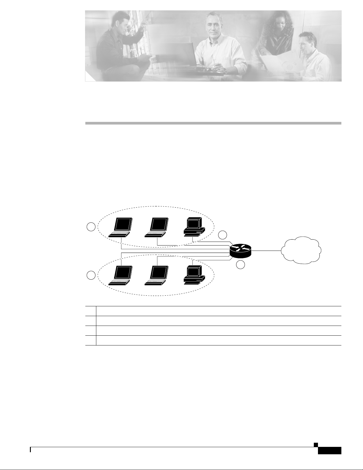
CHA P TER
5
Configuring a LAN with DHCP and VLANs
The Cisco 870 series routers support clients on both physical LANs and virtual LANs (VLANs). The
routers can use the Dynamic Host Configuration Protocol (DHCP) to enable automatic assignment of IP
configurations for nodes on these networks.
Figure 5-1 shows a typical deployment scenario with two physical LANs connected by the router and
two VLANs.
Figure 5-1 Physical and Virtual LANs with DHCP Configured on the Cisco Router
3
1
2
4
92339
1 Fast Ethernet LAN (with multiple networked devices)
2 Router and DHCP server—Cisco 870 series access router—connected to the Internet
3 VLAN 1
4 VLAN 2
DHCP
DHCP, which is described in RFC 2131, uses a client/server model for address allocation. As an
administrator, you can configure your Cisco
address assignment and other TCP/IP-oriented configuration information to your workstations. DHCP
frees you from having to manually assign an IP address to each client.
800 series router to act as a DHCP server, providing IP
OL-5332-01
Cisco 850 Series and Cisco 870 Series Access Routers Software Configuration Guide
5-1
Page 60

Configure DHCP
Note Whenever you change server properties, you must reload the server with the configuration data from the
Chapter 5 Configuring a LAN with DHCP and VLANs
When you configure a DHCP server, you must configure the server properties, policies, and DHCP
options.
Network Registrar database.
VLANs
The Cisco 870 series access routers support four Fast Ethernet ports on which you can configure
VLANs.
VLANs enable networks to be segmented and formed into logical groups of users, regardless of the
user’s physical location or LAN connection.
Configuration Tasks
Perform the following tasks to configure this network scenario:
• Configure DHCP
• Configure VLANs
Note The procedures in this chapter assume you have already configured basic router features as well as
PPPoE or PPPoA with NAT. If you have not performed these configurations tasks, see
Router Configuration,” Chapter 3, “Configuring PPP over Ethernet with NAT,” and Chapter 4,
“Configuring PPP over ATM with NAT” as appropriate for your router.
Configure DHCP
Perform these steps to configure your router for DHCP operation, beginning in global configuration
mode:
Command Purpose
Step 1
Step 2
ip domain name name
Example:
Router(config)# ip domain name smallbiz.com
Router(config)#
ip name-server server-address1
[server-address2...server-address6]
Example:
Router(config)# ip name-server 192.168.11.12
Router(config)#
Chapter 1, “Basic
Identifies the default domain that the router uses to
complete unqualified hostnames (names without a
dotted-decimal domain name).
Specifies the address of one or more Domain Name
System (DNS) servers to use for name and address
resolution.
5-2
Cisco 850 Series and Cisco 870 Series Access Routers Software Configuration Guide
OL-5332-01
Page 61

Chapter 5 Configuring a LAN with DHCP and VLANs
Command Purpose
Step 3
ip dhcp excluded-address low-address
[high-address]
Example:
Router(config)# ip dhcp excluded-address
192.168.9.0
Configure DHCP
Specifies IP addresses that the DHCP server should
not assign to DHCP clients. In this example, we are
excluding the router address.
Step 4
Step 5
Step 6
Step 7
ip dhcp pool name
Example:
Router(config)# ip dhcp pool dpool1
Router(config-dhcp)#
network network-number [mask | prefix-length]
Example:
Router(config-dhcp)# network 10.10.0.0
255.255.255.0
Router(config-dhcp)#
import all
Example:
Router(config-dhcp)# import all
Router(config-dhcp)#
default-router address [address2...address8]
Example:
Router(config-dhcp)# default-router
10.10.10.10
Router(config-dhcp)#
Creates a DHCP address pool on the router and
enters DHCP pool configuration mode. The name
argument can be a string or an integer.
Defines subnet number (IP) address for the DHCP
address pool, optionally including the mask.
Imports DHCP option parameters into the DHCP
portion of the router database.
Specifies up to 8 default routers for a DHCP client.
OL-5332-01
Step 8
dns-server address [address2...address8]
Example:
Router(config-dhcp)# dns-server 192.168.35.2
Router(config-dhcp)#
Cisco 850 Series and Cisco 870 Series Access Routers Software Configuration Guide
Specifies up to 8 DNS servers available to a DHCP
client.
5-3
Page 62

Configure DHCP
Step 9
Command Purpose
domain-name domain
Example:
Router(config-dhcp)# domain-name cisco.com
Router(config-dhcp)#
Specifies the domain name for a DHCP client.
Chapter 5 Configuring a LAN with DHCP and VLANs
Step 10
exit
Example:
Router(config-dhcp)# exit
Router(config)#
Configuration Example
The following configuration example shows a portion of the configuration file for the DCHP
configuration described in this chapter.
ip dhcp excluded-address 192.168.9.0
!
ip dhcp pool dpool1
import all
network 10.10.0.0 255.255.255.0
default-router 10.10.10.10
dns-server 192.168.35.2
domain-name cisco.com
!
ip domain name smallbiz.com
ip name-server 192.168.11.12
Exits DHCP configuration mode, and enters global
configuration mode.
Verify Your DHCP Configuration
Use the following commands to view your DHCP configuration.
• show ip dhcp import—Displays the optional parameters imported into the DHCP server database.
• show ip dhcp pool—Displays information about the DHCP address pools.
• show ip dhcp server statistics—Displays the DHCP server statistics, such as the number of address
pools, bindings, and so forth.
Router# show ip dhcp import
Address Pool Name: dpool1
Router# show ip dhcp pool
Pool dpool1 :
Utilization mark (high/low) : 100 / 0
Subnet size (first/next) : 0 / 0
Total addresses : 254
Leased addresses : 0
Pending event : none
1 subnet is currently in the pool :
Current index IP address range Leased addresses
10.10.0.1 10.10.0.1 - 10.10.0.254 0
Cisco 850 Series and Cisco 870 Series Access Routers Software Configuration Guide
5-4
OL-5332-01
Page 63

Chapter 5 Configuring a LAN with DHCP and VLANs
Router# show ip dhcp server statistics
Memory usage 15419
Address pools 1
Database agents 0
Automatic bindings 0
Manual bindings 0
Expired bindings 0
Malformed messages 0
Secure arp entries 0
Message Received
BOOTREQUEST 0
DHCPDISCOVER 0
DHCPREQUEST 0
DHCPDECLINE 0
DHCPRELEASE 0
DHCPINFORM 0
Message Sent
BOOTREPLY 0
DHCPOFFER 0
DHCPACK 0
DHCPNAK 0
Router#
Configure VLANs
Configure VLANs
Perform these steps to configure VLANs on your router, beginning in global configuration mode:
Command Purpose
Step 1
Step 2
Step 3
vlan ?
Example:
Router# config t
Router(config)#vlan ?
WORD ISL VLAN IDs 1-4094
accounting VLAN accounting configuration
ifdescr VLAN subinterface ifDescr
Router(config)#vlan
ISL VLAN ID
Example:
Router(config)#vlan 2
Router(config-vlan)#
exit
Example:
Router(config-vlan)#exit
Router(config)#
Enters VLAN configuration mode.
Adds VLANs, with identifiers ranging from
1- 4094.
For details about this command and additional
parameters that can be set, see the
Cisco IOS
Switching Services Command Reference.
Updates the VLAN database, propagates it throughout
the administrative domain, and returns to global
configuration mode.
OL-5332-01
Cisco 850 Series and Cisco 870 Series Access Routers Software Configuration Guide
5-5
Page 64

Configure VLANs
Assign a Switch Port to a VLAN
Perform these steps to assign a switch port to a VLAN, beginning in global configuration mode:
Command Purpose
Step 1
interface switch port id
Example:
Router(config)# interface FastEthernet 2
Router(config-if)#
Chapter 5 Configuring a LAN with DHCP and VLANs
Specifies the switch port that you want to assign
to the VLAN.
Step 2
switchport access vlan vlan-id
Example:
Router(config-if)# switchport access vlan 2
Router(config-if)#
Step 3
end
Example:
Router(config-if)# end
Router#
Verify Your VLAN Configuration
Use the following commands to view your VLAN configuration.
• show—Entered from VLAN database mode. Displays summary configuration information for all
configured VLANs.
• show vlan-switch—Entered from privileged EXEC mode. Displays detailed configuration
information for all configured VLANs.
Router# vlan database
Router(vlan)# show
Assigns a port to the VLAN.
Exits interface mode and returns to privileged
EXEC mode.
5-6
VLAN ISL Id: 1
Name: default
Media Type: Ethernet
VLAN 802.10 Id: 100001
State: Operational
MTU: 1500
Translational Bridged VLAN: 1002
Translational Bridged VLAN: 1003
VLAN ISL Id: 2
Name: VLAN0002
Media Type: Ethernet
VLAN 802.10 Id: 100002
State: Operational
MTU: 1500
Cisco 850 Series and Cisco 870 Series Access Routers Software Configuration Guide
OL-5332-01
Page 65

Chapter 5 Configuring a LAN with DHCP and VLANs
VLAN ISL Id: 3
Name: red-vlan
Media Type: Ethernet
VLAN 802.10 Id: 100003
State: Operational
MTU: 1500
VLAN ISL Id: 1002
Name: fddi-default
Media Type: FDDI
VLAN 802.10 Id: 101002
State: Operational
MTU: 1500
Bridge Type: SRB
Translational Bridged VLAN: 1
Translational Bridged VLAN: 1003
VLAN ISL Id: 1003
Name: token-ring-default
Media Type: Token Ring
VLAN 802.10 Id: 101003
State: Operational
MTU: 1500
Bridge Type: SRB
Ring Number: 0
Bridge Number: 1
Parent VLAN: 1005
Maximum ARE Hop Count: 7
Maximum STE Hop Count: 7
Backup CRF Mode: Disabled
Translational Bridged VLAN: 1
Translational Bridged VLAN: 1002
Configure VLANs
VLAN ISL Id: 1004
Name: fddinet-default
Media Type: FDDI Net
VLAN 802.10 Id: 101004
State: Operational
MTU: 1500
Bridge Type: SRB
Bridge Number: 1
STP Type: IBM
VLAN ISL Id: 1005
Name: trnet-default
Media Type: Token Ring Net
VLAN 802.10 Id: 101005
State: Operational
MTU: 1500
Bridge Type: SRB
Bridge Number: 1
STP Type: IBM
Router# show vlan-switch
VLAN Name Status Ports
---- -------------------------------- --------- ------------------------------1 default active Fa0, Fa1, Fa3
2 VLAN0002 active Fa2
1002 fddi-default active
1003 token-ring-default active
1004 fddinet-default active
1005 trnet-default active
OL-5332-01
Cisco 850 Series and Cisco 870 Series Access Routers Software Configuration Guide
5-7
Page 66

Configure VLANs
Chapter 5 Configuring a LAN with DHCP and VLANs
VLAN Type SAID MTU Parent RingNo BridgeNo Stp BrdgMode Trans1 Trans2
---- ----- ---------- ----- ------ ------ -------- ---- -------- ------ -----1 enet 100001 1500 - - - - - 1002 1003
2 enet 100002 1500 - - - - - 0 0
1002 fddi 101002 1500 - - - - - 1 1003
1003 tr 101003 1500 1005 0 - - srb 1 1002
1004 fdnet 101004 1500 - - 1 ibm - 0 0
1005 trnet 101005 1500 - - 1 ibm - 0 0
5-8
Cisco 850 Series and Cisco 870 Series Access Routers Software Configuration Guide
OL-5332-01
Page 67

CHA P TER
6
Configuring a VPN Using Easy VPN and an IPSec Tunnel
The Cisco 870 series routers support the creation of Virtual Private Networks (VPNs).
Cisco routers and other broadband devices provide high-performance connections to the Internet, but
many applications also require the security of VPN connections which perform a high level of
authentication and which encrypt the data between two particular endpoints.
Two types of VPNs are supported—site-to-site and remote access. Site-to-site VPNs are used to connect
branch offices to corporate offices, for example. Remote access VPNs are used by remote clients to log
in to a corporate network.
The example in this chapter illustrates the configuration of a remote access VPN that uses the Cisco Easy
VPN and an IPSec tunnel to configure and secure the connection between the remote client and the
corporate network.
Figure 6-1 shows a typical deployment scenario.
Note The material in this chapter does not apply to Cisco 850 series routers. Cisco 850 series routers do not
support Cisco Easy VPN.
OL-5332-01
Cisco 850 Series and Cisco 870 Series Access Routers Software Configuration Guide
6-1
Page 68

Chapter 6 Configuring a VPN Using Easy VPN and an IPSec Tunnel
Figure 6-1 Remote Access VPN Using IPSec Tunnel
5
3
4
2
Internet
6
121782
1
1 Remote, networked users
2 VPN client—Cisco 870 series access router
3 Router—Providing the corporate office network access
4 VPN server—Easy VPN server; for example, a Cisco VPN 3000 concentrator with outside
interface address 210.110.101.1
5 Corporate office with a network address of 10.1.1.1
6 IPSec tunnel
6-2
Cisco Easy VPN
The Cisco Easy VPN client feature eliminates much of the tedious configuration work by implementing
the Cisco Unity Client protocol. This protocol allows most VPN parameters, such as internal IP
addresses, internal subnet masks, DHCP server addresses, WINS server addresses, and split-tunneling
flags, to be defined at a VPN server, such as a Cisco VPN 3000 series concentrator that is acting as an
IPSec server.
An Easy VPN server–enabled device can terminate VPN tunnels initiated by mobile and remote workers
who are running Cisco Easy VPN Remote software on PCs. Easy VPN server–enabled devices allow
remote routers to act as Easy VPN Remote nodes.
The Cisco Easy VPN client feature can be configured in one of two modes—client mode or network
extension mode. Client mode is the default configuration and allows only devices at the client site to
access resources at the central site. Resources at the client site are unavailable to the central site.
Network extension mode allows users at the central site (where the VPN 3000 series concentrator is
located) to access network resources on the client site.
After the IPSec server has been configured, a VPN connection can be created with minimal configuration
on an IPSec client, such as a supported Cisco
870 series access router. When the IPSec client initiates
the VPN tunnel connection, the IPSec server pushes the IPSec policies to the IPSec client and creates
the corresponding VPN tunnel connection.
Cisco 850 Series and Cisco 870 Series Access Routers Software Configuration Guide
OL-5332-01
Page 69

Chapter 6 Configuring a VPN Using Easy VPN and an IPSec Tunnel
Note The Cisco Easy VPN client feature supports configuration of only one destination peer. If your
application requires creation of multiple VPN tunnels, you must manually configure the IPSec VPN and
Network Address Translation/Peer Address Translation (NAT/PAT) parameters on both the client and the
server.
Configuration Tasks
Perform the following tasks to configure your router for this network scenario:
• Configure the IKE Policy
• Configure Group Policy Information
• Apply Mode Configuration to the Crypto Map
• Enable Policy Lookup
• Configure IPSec Transforms and Protocols
• Configure the IPSec Crypto Method and Parameters
• Apply the Crypto Map to the Physical Interface
• Create an Easy VPN Remote Configuration
An example showing the results of these configuration tasks is provided in the “Configuration Example”
section on page 6-11.
Note The procedures in this chapter assume that you have already configured basic router features as well as
PPPoE or PPPoA with NAT, DCHP and VLANs. If you have not performed these configurations tasks,
see
Chapter 1, “Basic Router Configuration,” Chapter 3, “Configuring PPP over Ethernet with NAT,”
Chapter 4, “Configuring PPP over ATM with NAT,” and Chapter 5, “Configuring a LAN with DHCP
and VLANs” as appropriate for your router.
Note The examples shown in this chapter refer only to the endpoint configuration on the Cisco 870 series
router. Any VPN connection requires both endpoints be configured properly to function. See the
software configuration documentation as needed to configure VPN for other router models.
OL-5332-01
Cisco 850 Series and Cisco 870 Series Access Routers Software Configuration Guide
6-3
Page 70

Configure the IKE Policy
Configure the IKE Policy
Perform these steps to configure the Internet Key Exchange (IKE) policy, beginning in global
configuration mode:
Command or Action Purpose
Step 1
Step 2
crypto isakmp policy priority
Example:
Router(config)# crypto isakmp policy 1
Router(config-isakmp)#
encryption {des | 3des | aes | aes 192 | aes 256}
Example:
Router(config-isakmp)# encryption 3des
Router(config-isakmp)#
Chapter 6 Configuring a VPN Using Easy VPN and an IPSec Tunnel
Creates an IKE policy that is used during IKE
negotiation. The priority is a number from 1 to
10000, with 1 being the highest.
Also enters the Internet Security Association Key
and Management Protocol (ISAKMP) policy
configuration mode.
Specifies the encryption algorithm used in the IKE
policy.
The example specifies 168-bit data encryption
standard (DES).
Step 3
Step 4
Step 5
Step 6
hash {md5 | sha}
Example:
Router(config-isakmp)# hash md5
Router(config-isakmp)#
authentication {rsa-sig | rsa-encr | pre-share}
Example:
Router(config-isakmp)# authentication
pre-share
Router(config-isakmp)#
group {1 | 2 | 5}
Example:
Router(config-isakmp)# group 2
Router(config-isakmp)#
lifetime seconds
Example:
Router(config-isakmp)# lifetime 480
Router(config-isakmp)#
Specifies the hash algorithm used in the IKE
policy.
The example specifies the Message Digest 5
(MD5) algorithm. The default is Secure Hash
standard (SHA-1).
Specifies the authentication method used in the
IKE policy.
The example specifies a pre-shared key.
Specifies the Diffie-Hellman group to be used in
an IKE policy.
Specifies the lifetime, 60–86400 seconds, for an
IKE security association (SA).
6-4
Step 7
exit
Exits IKE policy configuration mode, and enters
global configuration mode.
Example:
Router(config-isakmp)# exit
Router(config)#
Cisco 850 Series and Cisco 870 Series Access Routers Software Configuration Guide
OL-5332-01
Page 71

Chapter 6 Configuring a VPN Using Easy VPN and an IPSec Tunnel
Configure Group Policy Information
Perform these steps to configure the group policy, beginning in global configuration mode:
Command or Action Purpose
Step 1
crypto isakmp client configuration group
{group-name | default}
Example:
Router(config)# crypto isakmp client
configuration group rtr-remote
Router(config-isakmp-group)#
Configure Group Policy Information
Creates an IKE policy group containing attributes
to be downloaded to the remote client.
Also enters the Internet Security Association Key
and Management Protocol (ISAKMP) group
policy configuration mode.
Step 2
Step 3
Step 4
Step 5
key name
Example:
Router(config-isakmp-group)# key
secret-password
Router(config-isakmp-group)#
dns primary-server
Example:
Router(config-isakmp-group)# dns 10.50.10.1
Router(config-isakmp-group)#
domain name
Example:
Router(config-isakmp-group)# domain
company.com
Router(config-isakmp-group)#
exit
Example:
Router(config-isakmp-group)# exit
Router(config)#
Specifies the IKE pre-shared key for the group
policy.
Specifies the primary Domain Name System
(DNS) server for the group.
Note You may also want to specify Windows
Internet Naming Service (WINS) servers
for the group by using the wins command.
Specifies group domain membership.
Exits IKE group policy configuration mode, and
enters global configuration mode.
OL-5332-01
Step 6
ip local pool {default | poolname}
[low-ip-address [high-ip-address]]
Example:
Router(config)# ip local pool dynpool
30.30.30.20 30.30.30.30
Router(config)#
Cisco 850 Series and Cisco 870 Series Access Routers Software Configuration Guide
Specifies a local address pool for the group.
For details about this command and additional
parameters that can be set, see the
Cisco IOS Dial
Technologies Command Reference.
6-5
Page 72

Chapter 6 Configuring a VPN Using Easy VPN and an IPSec Tunnel
Apply Mode Configuration to the Crypto Map
Apply Mode Configuration to the Crypto Map
Perform these steps to apply mode configuration to the crypto map, beginning in global configuration
mode:
Command or Action Purpose
Step 1
crypto map map-name isakmp authorization list
list-name
Example:
Router(config)# crypto map dynmap isakmp
authorization list rtr-remote
Router(config)#
Applies mode configuration to the crypto map and
enables key lookup (IKE queries) for the group
policy from an authentication, authorization, and
accounting (AAA) server.
Step 2
crypto map tag client configuration address
[initiate | respond]
Example:
Router(config)# crypto map dynmap client
configuration address respond
Router(config)#
Enable Policy Lookup
Perform these steps to enable policy lookup through AAA, beginning in global configuration mode:
Command or Action Purpose
Step 1
Step 2
aaa new-model
Example:
Router(config)# aaa new-model
Router(config)#
aaa authentication login {default | list-name}
method1 [method2...]
Example:
Router(config)# aaa authentication login
rtr-remote local
Router(config)#
Configures the router to reply to mode
configuration requests from remote clients.
Enables the AAA access control model.
Specifies AAA authentication of selected users at
login, and specifies the method used.
This example uses a local authentication database.
You could also use a RADIUS server for this. For
details, see the
Cisco IOS Security Configuration
Guide and Cisco IOS Security Command
Reference.
6-6
Cisco 850 Series and Cisco 870 Series Access Routers Software Configuration Guide
OL-5332-01
Page 73

Chapter 6 Configuring a VPN Using Easy VPN and an IPSec Tunnel
Command or Action Purpose
Step 3
aaa authorization {network | exec | commands
level | reverse-access | configuration} {default |
list-name} [method1 [method2...]]
Example:
Router(config)# aaa authorization network
rtr-remote local
Router(config)#
Configure IPSec Transforms and Protocols
Specifies AAA authorization of all
network-related service requests, including PPP,
and specifies the method of authorization.
This example uses a local authorization database.
You could also use a RADIUS server for this. For
details, see the
Guide and Cisco IOS Security Command
Reference.
Cisco IOS Security Configuration
Step 4
username name {nopassword | password
password | password encryption-type
encrypted-password}
Example:
Router(config)# username Cisco password 0
Cisco
Router(config)#
Establishes a username-based authentication
system.
This example implements a username of Cisco
with an encrypted password of Cisco.
Configure IPSec Transforms and Protocols
A transform set represents a certain combination of security protocols and algorithms. During IKE
negotiation, the peers agree to use a particular transform set for protecting data flow.
During IKE negotiations, the peers search in multiple transform sets for a transform that is the same at
both peers. When such a transform set is found, it is selected and applied to the protected traffic as a part
of both peers’ configurations.
OL-5332-01
Cisco 850 Series and Cisco 870 Series Access Routers Software Configuration Guide
6-7
Page 74

Configure the IPSec Crypto Method and Parameters
Perform these steps to specify the IPSec transform set and protocols, beginning in global configuration
mode:
Command or Action Purpose
Step 1
crypto ipsec transform-set transform-set-name
transform1 [transform2] [transform3]
[transform4]
Example:
Router(config)# crypto ipsec transform-set
vpn1 esp-3des esp-sha-hmac
Router(config)#
Chapter 6 Configuring a VPN Using Easy VPN and an IPSec Tunnel
Defines a transform set—an acceptable
combination of IPSec security protocols and
algorithms.
See the Cisco IOS Security Command Reference
for detail about the valid transforms and
combinations.
Step 2
Note With manually established security associations, there is no negotiation with the peer, and both sides
crypto ipsec security-association lifetime
{seconds seconds | kilobytes kilobytes}
Example:
Router(config)# crypto ipsec
security-association lifetime seconds 86400
Router(config)#
Specifies global lifetime values used when IPSec
security associations are negotiated.
See the Cisco IOS Security Command Reference
for details.
must specify the same transform set.
Configure the IPSec Crypto Method and Parameters
A dynamic crypto map policy processes negotiation requests for new security associations from remote
IPSec peers, even if the router does not know all the crypto map parameters (for example, IP address).
Perform these steps to configure the IPSec crypto method, beginning in global configuration mode:
Command or Action Purpose
Step 1
crypto dynamic-map dynamic-map-name
dynamic-seq-num
Creates a dynamic crypto map entry and enters
crypto map configuration mode.
6-8
Example:
Router(config)# crypto dynamic-map dynmap 1
Router(config-crypto-map)#
Step 2
set transform-set transform-set-name
[transform-set-name2...transform-set-name6]
Example:
Router(config-crypto-map)# set
transform-set vpn1
Router(config-crypto-map)#
Cisco 850 Series and Cisco 870 Series Access Routers Software Configuration Guide
See the Cisco IOS Security Command Reference
for more detail about this command.
Specifies which transform sets can be used with
the crypto map entry.
OL-5332-01
Page 75

Chapter 6 Configuring a VPN Using Easy VPN and an IPSec Tunnel
Command or Action Purpose
Step 3
reverse-route
Example:
Router(config-crypto-map)# reverse-route
Router(config-crypto-map)#
Apply the Crypto Map to the Physical Interface
Creates source proxy information for the crypto
map entry.
See the Cisco IOS Security Command Reference
for details.
Step 4
Step 5
exit
Example:
Router(config-crypto-map)# exit
Router(config)#
crypto map map-name seq-num [ipsec-isakmp]
Returns to global configuration mode.
Creates a crypto map profile.
[dynamic dynamic-map-name] [discover]
[profile profile-name]
Example:
Router(config)# crypto map static-map 1
ipsec-isakmp dynamic dynmap
Router(config)#
Apply the Crypto Map to the Physical Interface
The crypto maps must be applied to each interface through which IP Security (IPSec) traffic flows.
Applying the crypto map to the physical interface instructs the router to evaluate all the traffic against
the security associations database. With the default configurations, the router provides secure
connectivity by encrypting the traffic sent between remote sites. However, the public interface still
allows the rest of the traffic to pass and provides connectivity to the Internet.
Perform these steps to apply a crypto map to an interface, beginning in global configuration mode:
OL-5332-01
Step 1
Command or Action Purpose
interface type number
Enters the interface configuration mode for the
interface to which you want the crypto map
Example:
Router(config)# interface fastethernet 4
Router(config-if)#
Cisco 850 Series and Cisco 870 Series Access Routers Software Configuration Guide
applied.
6-9
Page 76

Create an Easy VPN Remote Configuration
Command or Action Purpose
Step 2
crypto map map-name
Example:
Router(config-if)# crypto map static-map
Router(config-if)#
Chapter 6 Configuring a VPN Using Easy VPN and an IPSec Tunnel
Applies the crypto map to the interface.
See the Cisco IOS Security Command Reference
for more detail about this command.
Step 3
exit
Returns to global configuration mode.
Example:
Router(config-crypto-map)# exit
Router(config)#
Create an Easy VPN Remote Configuration
The router acting as the IPSec remote router must create an Easy VPN remote configuration and assign
it to the outgoing interface.
Perform these steps to create the remote configuration, beginning in global configuration mode:
Command or Action Purpose
Step 1
Step 2
crypto ipsec client ezvpn name
Example:
Router(config)# crypto ipsec client ezvpn
ezvpnclient
Router(config-crypto-ezvpn)#
group group-name key group-key
Example:
Router(config-crypto-ezvpn)# group
ezvpnclient key secret-password
Router(config-crypto-ezvpn)#
Creates a Cisco Easy VPN remote configuration,
and enters Cisco Easy VPN remote configuration
mode.
Specifies the IPSec group and IPSec key value for
the VPN connection.
6-10
Step 3
peer {ipaddress | hostname}
Specifies the peer IP address or hostname for the
VPN connection.
Step 4
Example:
Router(config-crypto-ezvpn)# peer
192.168.100.1
Router(config-crypto-ezvpn)#
mode {client | network-extension | network
Note A hostname can be specified only when
Specifies the VPN mode of operation.
extension plus}
Example:
Router(config-crypto-ezvpn)# mode client
Router(config-crypto-ezvpn)#
Cisco 850 Series and Cisco 870 Series Access Routers Software Configuration Guide
the router has a DNS server available for
hostname resolution.
OL-5332-01
Page 77

Chapter 6 Configuring a VPN Using Easy VPN and an IPSec Tunnel
Command or Action Purpose
Step 5
exit
Example:
Router(config-crypto-ezvpn)# exit
Router(config)#
Verifying Your Easy VPN Configuration
Returns to global configuration mode.
Step 6
interface type number
Enters the interface configuration mode for the
interface to which you want the Cisco Easy VPN
remote configuration applied.
Note For routers with an ATM WAN interface,
Assigns the Cisco Easy VPN remote configuration
Step 7
Example:
Router(config)# interface fastethernet 4
Router(config-if)#
crypto ipsec client ezvpn name [outside | inside]
to the WAN interface, causing the router to
automatically create the NAT or port address
translation (PAT) and access list configuration
needed for the VPN connection.
Returns to global configuration mode.
Step 8
Example:
Router(config-if)# crypto ipsec client
ezvpn ezvpnclient outside
Router(config-if)#
exit
Example:
Router(config-crypto-ezvpn)# exit
Router(config)#
Verifying Your Easy VPN Configuration
Router# show crypto ipsec client ezvpn
this command would be interface atm 0.
Tunnel name :ezvpnclient
Inside interface list:vlan 1
Outside interface:fastethernet 4
Current State:IPSEC_ACTIVE
Last Event:SOCKET_UP
Address:8.0.0.5
Mask:255.255.255.255
Default Domain:cisco.com
Configuration Example
The following configuration example shows a portion of the configuration file for the VPN and IPSec
tunnel described in this chapter.
!
aaa new-model
!
aaa authentication login rtr-remote local
aaa authorization network rtr-remote local
aaa session-id common
OL-5332-01
Cisco 850 Series and Cisco 870 Series Access Routers Software Configuration Guide
6-11
Page 78

Configuration Example
Chapter 6 Configuring a VPN Using Easy VPN and an IPSec Tunnel
!
username Cisco password 0 Cisco
!
crypto isakmp policy 1
encryption 3des
authentication pre-share
group 2
lifetime 480
!
crypto isakmp client configuration group rtr-remote
key secret-password
dns 10.50.10.1 10.60.10.1
domain company.com
pool dynpool
!
crypto ipsec transform-set vpn1 esp-3des esp-sha-hmac
!
crypto ipsec security-association lifetime seconds 86400
!
crypto dynamic-map dynmap 1
set transform-set vpn1
reverse-route
!
crypto map static-map 1 ipsec-isakmp dynamic dynmap
crypto map dynmap isakmp authorization list rtr-remote
crypto map dynmap client configuration address respond
crypto ipsec client ezvpn ezvpnclient
connect auto
group 2 key secret-password
mode client
peer 192.168.100.1
!
interface fastethernet 4
crypto ipsec client ezvpn ezvpnclient outside
crypto map static-map
!
interface vlan 1
crypto ipsec client ezvpn ezvpnclient inside
!
6-12
Cisco 850 Series and Cisco 870 Series Access Routers Software Configuration Guide
OL-5332-01
Page 79

CHA P TER
7
Configuring VPNs Using an IPSec Tunnel and Generic Routing Encapsulation
The Cisco 850 and Cisco 870 series routers support the creation of virtual private networks (VPNs).
Cisco routers and other broadband devices provide high-performance connections to the Internet, but
many applications also require the security of VPN connections which perform a high level of
authentication and which encrypt the data between two particular endpoints.
Two types of VPNs are supported—site-to-site and remote access. Site-to-site VPNs are used to connect
branch offices to corporate offices, for example. Remote access VPNs are used by remote clients to log
in to a corporate network.
The example in this chapter illustrates the configuration of a site-to-site VPN that uses IPSec and the
generic routing encapsulation (GRE) protocol to secure the connection between the branch office and
the corporate network.
Figure 7-1 shows a typical deployment scenario.
Figure 7-1 Site-to-Site VPN Using an IPSec Tunnel and GRE
8
3
2 4 5 7
Internet
1
9
1 Branch office containing multiple LANs and VLANs
2 Fast Ethernet LAN interface—With address 192.168.0.0/16 (also the inside interface for NAT)
3 VPN client—Cisco 850 or Cisco 870 series access router
4 Fast Ethernet or ATM interface—With address 200.1.1.1 (also the outside interface for NAT)
5 LAN interface—Connects to the Internet; with outside interface address of 210.110.101.1
6 VPN client—Another router, which controls access to the corporate network
7 LAN interface—Connects to the corporate network, with inside interface address of 10.1.1.1
8 Corporate office network
9 IPSec tunnel with GRE
6
121783
OL-5332-01
Cisco 850 Series and Cisco 870 Series Access Routers Software Configuration Guide
7-1
Page 80

Configure a VPN
Note When IP Security (IPSec) is used with GRE, the access list for encrypting traffic does not list the desired
Chapter 7 Configuring VPNs Using an IPSec Tunnel and Generic Routing Encapsulation
GRE Tunnels
GRE tunnels are typically used to establish a VPN between the Cisco router and a remote device that
controls access to a private network, such as a corporate network. Traffic forwarded through the GRE
tunnel is encapsulated and routed out onto the physical interface of the router. When a GRE interface is
used, the Cisco router and the router that controls access to the corporate network can support dynamic
IP routing protocols to exchange routing updates over the tunnel, and to enable IP multicast traffic.
Supported IP routing protocols include Enhanced Interior Gateway Routing Protocol (EIGRP), Routing
Information Protocol (RIP), Intermediate System-to-Intermediate System (IS-IS), Open Shortest Path
First (OSPF), and Border Gateway Protocol (BGP).
end network and applications, but instead refers to the permitted source and destination of the GRE
tunnel in the outbound direction. All packets forwarded to the GRE tunnel are encrypted if no further
access control lists (ACLs) are applied to the tunnel interface.
VPNs
VPN configuration information must be configured on both endpoints; for example, on your Cisco router
and at the remote user, or on your Cisco router and on another router. You must specify parameters, such
as internal IP addresses, internal subnet masks, DHCP server addresses, and Network Address
Translation (NAT).
Configuration Tasks
Perform the following tasks to configure this network scenario:
• Configure a VPN
• Configure a GRE Tunnel
A configuration example showing the results of these configuration tasks is provided in the
“Configuration Example” section on page 7-9.
Note The procedures in this chapter assume that you have already configured basic router features as well as
PPPoE or PPPoA with NAT, DCHP, and VLANs. If you have not performed these configurations tasks,
see
Chapter 1, “Basic Router Configuration,” Chapter 3, “Configuring PPP over Ethernet with NAT,”
Chapter 4, “Configuring PPP over ATM with NAT,” and Chapter 5, “Configuring a LAN with DHCP
and VLANs,” as appropriate for your router.
Configure a VPN
Perform the following tasks to configure a VPN over an IPSec tunnel:
• Configure the IKE Policy
• Configure Group Policy Information
• Enable Policy Lookup
• Configure IPSec Transforms and Protocols
7-2
• Configure the IPSec Crypto Method and Parameters
• Apply the Crypto Map to the Physical Interface
Cisco 850 Series and Cisco 870 Series Access Routers Software Configuration Guide
OL-5332-01
Page 81

Chapter 7 Configuring VPNs Using an IPSec Tunnel and Generic Routing Encapsulation
Configure the IKE Policy
Perform these steps to configure the Internet Key Exchange (IKE) policy, beginning in global
configuration mode:
Command or Action Purpose
Step 1
Step 2
crypto isakmp policy priority
Example:
Router(config)# crypto isakmp policy 1
Router(config-isakmp)#
encryption {des | 3des | aes | aes 192 | aes 256}
Example:
Router(config-isakmp)# encryption 3des
Router(config-isakmp)#
Configure a VPN
Creates an IKE policy that is used during IKE
negotiation. The priority is a number from 1 to
10000, with 1 being the highest.
Also enters Internet Security Association and Key
Management Protocol (ISAKMP) policy
configuration mode.
Specifies the encryption algorithm used in the IKE
policy.
The example uses 168-bit Data Encryption
Standard (DES).
Step 3
Step 4
Step 5
Step 6
hash {md5 | sha}
Example:
Router(config-isakmp)# hash md5
Router(config-isakmp)#
authentication {rsa-sig | rsa-encr | pre-share}
Example:
Router(config-isakmp)# authentication
pre-share
Router(config-isakmp)#
group {1 | 2 | 5}
Example:
Router(config-isakmp)# group 2
Router(config-isakmp)#
lifetime seconds
Example:
Router(config-isakmp)# lifetime 480
Router(config-isakmp)#
Specifies the hash algorithm used in the IKE
policy.
The example specifies the Message Digest 5
(MD5) algorithm. The default is Secure Hash
standard (SHA-1).
Specifies the authentication method used in the
IKE policy.
The example uses a pre-shared key.
Specifies the Diffie-Hellman group to be used in
the IKE policy.
Specifies the lifetime, 60–86400 seconds, for an
IKE security association (SA).
OL-5332-01
Step 7
exit
Example:
Router(config-isakmp)# exit
Router(config)#
Cisco 850 Series and Cisco 870 Series Access Routers Software Configuration Guide
Exits IKE policy configuration mode, and enters
global configuration mode.
7-3
Page 82

Chapter 7 Configuring VPNs Using an IPSec Tunnel and Generic Routing Encapsulation
Configure a VPN
Configure Group Policy Information
Perform these steps to configure the group policy, beginning in global configuration mode:
Command or Action Purpose
Step 1
crypto isakmp client configuration group
{group-name | default}
Example:
Router(config)# crypto isakmp client
configuration group rtr-remote
Router(config-isakmp-group)#
Creates an IKE policy group that contains
attributes to be downloaded to the remote client.
Also enters Internet Security Association Key
Management Protocol (ISAKMP) policy
configuration mode.
Step 2
Step 3
Step 4
Step 5
key name
Example:
Router(config-isakmp-group)# key
secret-password
Router(config-isakmp-group)#
dns primary-server
Example:
Router(config-isakmp-group)# dns 10.50.10.1
Router(config-isakmp-group)#
domain name
Example:
Router(config-isakmp-group)# domain
company.com
Router(config-isakmp-group)#
exit
Example:
Router(config-isakmp-group)# exit
Router(config)#
Specifies the IKE pre-shared key for the group
policy.
Specifies the primary Domain Name Service
(DNS) server for the group.
Note You may also want to specify Windows
Internet Naming Service (WINS) servers
for the group by using the wins command.
Specifies group domain membership.
Exits IKE group policy configuration mode, and
enters global configuration mode.
7-4
Step 6
Cisco 850 Series and Cisco 870 Series Access Routers Software Configuration Guide
ip local pool {default | poolname}
[low-ip-address [high-ip-address]]
Example:
Router(config)# ip local pool dynpool
30.30.30.20 30.30.30.30
Router(config)#
Specifies a local address pool for the group.
For details about this command and additional
parameters that can be set, see the
Technologies Command Reference.
Cisco IOS Dial
OL-5332-01
Page 83

Chapter 7 Configuring VPNs Using an IPSec Tunnel and Generic Routing Encapsulation
Enable Policy Lookup
Perform these steps to enable policy lookup through AAA, beginning in global configuration mode:
Command or Action Purpose
Step 1
aaa new-model
Example:
Router(config)# aaa new-model
Router(config)#
Configure a VPN
Enables the AAA access control model.
Step 2
Step 3
Step 4
aaa authentication login {default | list-name}
method1 [method2...]
Example:
Router(config)# aaa authentication login
rtr-remote local
Router(config)#
aaa authorization {network | exec | commands
level | reverse-access | configuration} {default |
list-name} [method1 [method2...]]
Example:
Router(config)# aaa authorization network
rtr-remote local
Router(config)#
username name {nopassword | password
password | password encryption-type
encrypted-password}
Example:
Router(config)# username cisco password 0
cisco
Router(config)#
Specifies AAA authentication of selected users at
login, and specifies the method used.
This example uses a local authentication database.
You could also use a RADIUS server for this. See
Cisco IOS Security Configuration Guide and
the
the Cisco IOS Security Command Reference for
details.
Specifies AAA authorization of all
network-related service requests, including PPP,
and the method used to do so.
This example uses a local authorization database.
You could also use a RADIUS server for this. See
Cisco IOS Security Configuration Guide and
the
the Cisco IOS Security Command Reference for
details.
Establishes a username-based authentication
system.
This example implements a username of cisco
with an encrypted password of cisco.
Configure IPSec Transforms and Protocols
A transform set represents a certain combination of security protocols and algorithms. During IKE
negotiation, the peers agree to use a particular transform set for protecting data flow.
During IKE negotiations, the peers search in multiple transform sets for a transform that is the same at
both peers. When such a transform set is found, it is selected and applied to the protected traffic as a part
of both peers’ configurations.
Cisco 850 Series and Cisco 870 Series Access Routers Software Configuration Guide
OL-5332-01
7-5
Page 84

Configure a VPN
Step 1
Chapter 7 Configuring VPNs Using an IPSec Tunnel and Generic Routing Encapsulation
Perform these steps to specify the IPSec transform set and protocols, beginning in global configuration
mode:
Command or Action Purpose
crypto ipsec transform-set transform-set-name
transform1 [transform2] [transform3]
[transform4]
Example:
Router(config)# crypto ipsec transform-set
vpn1 esp-3des esp-sha-hmac
Router(config)#
Defines a transform set—An acceptable
combination of IPSec security protocols and
algorithms.
See the Cisco IOS Security Command Reference
for detail about the valid transforms and
combinations.
Step 2
Note With manually established security associations, there is no negotiation with the peer, and both sides
crypto ipsec security-association lifetime
{seconds seconds | kilobytes kilobytes}
Example:
Router(config)# crypto ipsec
security-association lifetime seconds 86400
Router(config)#
Specifies global lifetime values used when
negotiating IPSec security associations.
See the Cisco IOS Security Command Reference
for details.
must specify the same transform set.
Configure the IPSec Crypto Method and Parameters
A dynamic crypto map policy processes negotiation requests for new security associations from remote
IPSec peers, even if the router does not know all the crypto map parameters (for example, IP address).
Perform these steps to configure the IPSec crypto method, beginning in global configuration mode:
Command or Action Purpose
Step 1
crypto dynamic-map dynamic-map-name
dynamic-seq-num
Creates a dynamic crypto map entry, and enters
crypto map configuration mode.
7-6
Example:
Router(config)# crypto dynamic-map dynmap 1
Router(config-crypto-map)#
Step 2
set transform-set transform-set-name
[transform-set-name2...transform-set-name6]
Example:
Router(config-crypto-map)# set
transform-set vpn1
Router(config-crypto-map)#
Cisco 850 Series and Cisco 870 Series Access Routers Software Configuration Guide
See the Cisco IOS Security Command Reference
for more detail about this command.
Specifies which transform sets can be used with
the crypto map entry.
OL-5332-01
Page 85

Chapter 7 Configuring VPNs Using an IPSec Tunnel and Generic Routing Encapsulation
Command or Action Purpose
Step 3
reverse-route
Example:
Router(config-crypto-map)# reverse-route
Router(config-crypto-map)#
Configure a VPN
Creates source proxy information for the crypto
map entry.
See the Cisco IOS Security Command Reference
for details.
Step 4
Step 5
exit
Example:
Router(config-crypto-map)# exit
Router(config)#
crypto map map-name seq-num [ipsec-isakmp]
[dynamic dynamic-map-name] [discover]
[profile profile-name]
Example:
Router(config)# crypto map static-map 1
ipsec-isakmp dynamic dynmap
Router(config)#
Apply the Crypto Map to the Physical Interface
The crypto maps must be applied to each interface through which IPSec traffic flows. Applying the
crypto map to the physical interface instructs the router to evaluate all the traffic against the security
associations database. With the default configurations, the router provides secure connectivity by
encrypting the traffic sent between remote sites. However, the public interface still allows the rest of the
traffic to pass and provides connectivity to the Internet.
Perform these steps to apply a crypto map to an interface, beginning in global configuration mode:
Enters global configuration mode.
Creates a crypto map profile.
OL-5332-01
Step 1
Command or Action Purpose
interface type number
Enters interface configuration mode for the
interface to which you want to apply the crypto
Example:
Router(config)# interface fastethernet 4
Router(config-if)#
Cisco 850 Series and Cisco 870 Series Access Routers Software Configuration Guide
map.
7-7
Page 86

Configure a GRE Tunnel
Step 2
Chapter 7 Configuring VPNs Using an IPSec Tunnel and Generic Routing Encapsulation
Command or Action Purpose
crypto map map-name
Example:
Router(config-if)# crypto map static-map
Router(config-if)#
Applies the crypto map to the interface.
See the Cisco IOS Security Command Reference
for more detail about this command.
Step 3
exit
Example:
Router(config-if)# exit
Router(config)#
Configure a GRE Tunnel
Perform these steps to configure a GRE tunnel, beginning in global configuration mode:
Command or Action Purpose
Step 1
Step 2
interface type number
Example:
Router(config)# interface tunnel 1
Router(config-if)#
ip address subnet mask
Example:
Router(config-if)# ip address 10.62.1.193
255.255.255.255
Router(config-if)#
Enters global configuration mode.
Creates a tunnel interface and enters interface
configuration mode.
Assigns an address to the tunnel.
7-8
Step 3
tunnel source interface-type number
Specifies the source endpoint of the router for the
GRE tunnel.
Example:
Router(config-if)# tunnel source
fastethernet 0
Router(config-if)#
Step 4
tunnel destination default-gateway-ip-address
Specifies the destination endpoint of the router for
the GRE tunnel.
Example:
Router(config-if)# tunnel destination
192.168.101.1
Router(config-if)#
Cisco 850 Series and Cisco 870 Series Access Routers Software Configuration Guide
OL-5332-01
Page 87

Chapter 7 Configuring VPNs Using an IPSec Tunnel and Generic Routing Encapsulation
Command or Action Purpose
Step 5
Step 6
crypto map map-name
Example:
Router(config-if)# crypto map static-map
Router(config-if)#
exit
Example:
Router(config-if)# exit
Router(config)#
Configuration Example
Assigns a crypto map to the tunnel.
Note Dynamic routing or static routes to the
tunnel interface must be configured to
establish connectivity between the sites.
See the
Cisco IOS Security Configuration
Guide for details.
Exits interface configuration mode, and returns to
global configuration mode.
Step 7
Step 8
Step 9
ip access-list {standard | extended}
access-list-name
Example:
Router(config)# ip access-list extended
vpnstatic1
Router(config-acl)#
permit protocol source source-wildcard
destination destination-wildcard
Example:
Router(config-acl)# permit gre host
192.168.100.1 host 192.168.101.1
Router(config-acl)#
exit
Example:
Router(config-acl)# exit
Router(config)#
Enters ACL configuration mode for the named
ACL that is used by the crypto map.
Specifies that only GRE traffic is permitted on the
outbound interface.
Returns to global configuration mode.
Configuration Example
The following configuration example shows a portion of the configuration file for a VPN using a GRE
tunnel scenario described in the preceding sections.
!
aaa new-model
!
aaa authentication login rtr-remote local
aaa authorization network rtr-remote local
aaa session-id common
!
username cisco password 0 cisco
!
interface tunnel 1
ip address 10.62.1.193 255.255.255.252
OL-5332-01
Cisco 850 Series and Cisco 870 Series Access Routers Software Configuration Guide
7-9
Page 88

Configuration Example
Chapter 7 Configuring VPNs Using an IPSec Tunnel and Generic Routing Encapsulation
tunnel source fastethernet 0
tunnel destination interface 192.168.101.1
ip route 20.20.20.0 255.255.255.0 tunnel 1
crypto isakmp policy 1
encryption 3des
authentication pre-share
group 2
!
crypto isakmp client configuration group rtr-remote
key secret-password
dns 10.50.10.1 10.60.10.1
domain company.com
pool dynpool
!
crypto ipsec transform-set vpn1 esp-3des esp-sha-hmac
!
crypto ipsec security-association lifetime seconds 86400
!
crypto dynamic-map dynmap 1
set transform-set vpn1
reverse-route
!
crypto map static-map 1 ipsec-isakmp dynamic dynmap
crypto map dynmap isakmp authorization list rtr-remote
crypto map dynmap client configuration address respond
!
! Defines the key association and authentication for IPSec tunnel.
crypto isakmp policy 1
hash md5
authentication pre-share
crypto isakmp key cisco123 address 200.1.1.1
!
!
! Defines encryption and transform set for the IPSec tunnel.
crypto ipsec transform-set set1 esp-3des esp-md5-hmac
!
! Associates all crypto values and peering address for the IPSec tunnel.
crypto map to_corporate 1 ipsec-isakmp
set peer 200.1.1.1
set transform-set set1
match address 105
!
!
! VLAN 1 is the internal interface
interface vlan 1
ip address 10.1.1.1 255.255.255.0
ip nat inside
ip inspect firewall in ! Inspection examines outbound traffic.
crypto map static-map
no cdp enable
!
! FE4 is the outside or Internet-exposed interface
interface fastethernet 4
ip address 210.110.101.21 255.255.255.0
! acl 103 permits IPSec traffic from the corp. router as well as
! denies Internet-initiated traffic inbound.
ip access-group 103 in
ip nat outside
no cdp enable
crypto map to_corporate ! Applies the IPSec tunnel to the outside interface.
7-10
Cisco 850 Series and Cisco 870 Series Access Routers Software Configuration Guide
OL-5332-01
Page 89

Chapter 7 Configuring VPNs Using an IPSec Tunnel and Generic Routing Encapsulation
!
! Utilize NAT overload in order to make best use of the
! single address provided by the ISP.
ip nat inside source list 102 interface Ethernet1 overload
ip classless
ip route 0.0.0.0 0.0.0.0 210.110.101.1
no ip http server
!
!
! acl 102 associated addresses used for NAT.
access-list 102 permit ip 10.1.1.0 0.0.0.255 any
! acl 103 defines traffic allowed from the peer for the IPSec tunnel.
access-list 103 permit udp host 200.1.1.1 any eq isakmp
access-list 103 permit udp host 200.1.1.1 eq isakmp any
access-list 103 permit esp host 200.1.1.1 any
! Allow ICMP for debugging but should be disabled because of security implications.
access-list 103 permit icmp any any
access-list 103 deny ip any any ! Prevents Internet-initiated traffic inbound.
! acl 105 matches addresses for the IPSec tunnel to or from the corporate network.
access-list 105 permit ip 10.1.1.0 0.0.0.255 192.168.0.0 0.0.255.255
no cdp run
Configuration Example
OL-5332-01
Cisco 850 Series and Cisco 870 Series Access Routers Software Configuration Guide
7-11
Page 90

Configuration Example
Chapter 7 Configuring VPNs Using an IPSec Tunnel and Generic Routing Encapsulation
7-12
Cisco 850 Series and Cisco 870 Series Access Routers Software Configuration Guide
OL-5332-01
Page 91

CHA P TER
8
Configuring a Simple Firewall
The Cisco 850 and Cisco 870 series routers support network traffic filtering by means of access lists.
The routers also support packet inspection and dynamic temporary access lists by means of
Context-Based Access Control (CBAC).
Basic traffic filtering is limited to configured access list implementations that examine packets at the
network layer or, at most, the transport layer, permitting or denying the passage of each packet through
the firewall. However, the use of inspection rules in CBAC allows the creation and use of dynamic
temporary access lists. These dynamic lists allow temporary openings in the configured access lists at
firewall interfaces. These openings are created when traffic for a specified user session exits the internal
network through the firewall. The openings allow returning traffic for the specified session (that would
normally be blocked) back through the firewall.
See the Cisco IOS Security Configuration Guide, Release 12.3, for more detailed information on traffic
filtering and firewalls.
Figure 8-1 shows a network deployment using PPPoE or PPPoA with NAT and a firewall.
Figure 8-1 Router with Firewall Configured
4
2
3
5 6
1
7
121781
OL-5332-01
Cisco 850 Series and Cisco 870 Series Access Routers Software Configuration Guide
8-1
Page 92

Chapter 8 Configuring a Simple Firewall
1 Multiple networked devices—Desktops, laptop PCs, switches
2 Fast Ethernet LAN interface (the inside interface for NAT)
3 PPPoE or PPPoA client and firewall implementation—Cisco 851/871 or Cisco 857/876/877/878
series access router, respectively
4 Point at which NAT occurs
5 Protected network
6 Unprotected network
7 Fast Ethernet or ATM WAN interface (the outside interface for NAT)
In the configuration example that follows, the firewall is applied to the outside WAN interface (FE4) on
the Cisco
traffic entering the router on the Fast Ethernet WAN interface FE4. Note that in this example, the network
traffic originating from the corporate network, network address 10.1.1.0, is considered safe traffic and
is not filtered.
Configuration Tasks
Perform the following tasks to configure this network scenario:
• Configure Access Lists
851 or Cisco 871 and protects the Fast Ethernet LAN on FE0 by filtering and inspecting all
• Configure Inspection Rules
• Apply Access Lists and Inspection Rules to Interfaces
A configuration example that shows the results of these configuration tasks is provided in the
“Configuration Example” section on page 8-5.
Note The procedures in this chapter assume that you have already configured basic router features as well as
PPPoE or PPPoA with NAT. If you have not performed these configurations tasks, see
Chapter 1, “Basic
Router Configuration,” Chapter 3, “Configuring PPP over Ethernet with NAT,” and Chapter 4,
“Configuring PPP over ATM with NAT,” as appropriate for your router. You may have also configured
DHCP, VLANs, and secure tunnels.
8-2
Cisco 850 Series and Cisco 870 Series Access Routers Software Configuration Guide
OL-5332-01
Page 93

Chapter 8 Configuring a Simple Firewall
Configure Access Lists
Perform these steps to create access lists for use by the firewall, beginning in global configuration mode:
Command Purpose
Step 1
access-list access-list-number {deny | permit}
protocol source source-wildcard [operator [port]]
destination
Example:
Router(config)# access-list 103 deny ip any
any
Router(config)# access-list 103 permit host
200.1.1.1 eq isakmp any
Router(config)#
Configure Access Lists
Creates an access list which prevents Internetinitiated traffic from reaching the local (inside)
network of the router, and which compares
source and destination ports.
See the Cisco IOS IP Command Reference,
Volume 1 of 4: Addressing and Services for
details about this command.
Configure Inspection Rules
Perform these steps to configure firewall inspection rules for all TCP and UDP traffic, as well as specific
application protocols as defined by the security policy, beginning in global configuration mode:
Command or Action Purpose
Step 1
Step 2
ip inspect name inspection-name protocol
Example:
Router(config)# ip inspect name firewall tcp
Router(config)#
ip inspect name inspection-name protocol
Example:
Router(config)# ip inspect name firewall rtsp
Router(config)# ip inspect name firewall h323
Router(config)# ip inspect name firewall
netshow
Router(config)# ip inspect name firewall ftp
Router(config)# ip inspect name firewall
sqlnet
Router(config)#
Defines an inspection rule for a particular
protocol.
Repeat this command for each inspection rule
that you wish to use.
OL-5332-01
Cisco 850 Series and Cisco 870 Series Access Routers Software Configuration Guide
8-3
Page 94

Chapter 8 Configuring a Simple Firewall
Apply Access Lists and Inspection Rules to Interfaces
Apply Access Lists and Inspection Rules to Interfaces
Perform these steps to apply the ACLs and inspection rules to the network interfaces, beginning in global
configuration mode:
Command Purpose
Step 1
interface type number
Example:
Router(config)# interface vlan 1
Router(config-if)#
Enters interface configuration mode for the
inside network interface on your router.
Step 2
Step 3
Step 4
Step 5
ip inspect inspection-name {in | out}
Example:
Router(config-if)# ip inspect firewall in
Router(config-if)#
exit
Example:
Router(config-if)# exit
Router(config)#
interface type number
Example:
Router(config)# interface fastethernet 4
Router(config-if)#
ip access-group {access-list-number |
access-list-name}{in | out}
Example:
Router(config-if)# ip access-group 103 in
Router(config-if)#
Assigns the set of firewall inspection rules to the
inside interface on the router.
Returns to global configuration mode.
Enters interface configuration mode for the
outside network interface on your router.
Assigns the defined ACLs to the outside
interface on the router.
8-4
Step 6
exit
Returns to global configuration mode.
Example:
Router(config-if)# exit
Router(config)#
Cisco 850 Series and Cisco 870 Series Access Routers Software Configuration Guide
OL-5332-01
Page 95

Chapter 8 Configuring a Simple Firewall
Configuration Example
A telecommuter is granted secure access to a corporate network, using IPSec tunneling. Security to the
home network is accomplished through firewall inspection. The protocols that are allowed are all TCP,
UDP, RTSP, H.323, NetShow, FTP, and SQLNet. There are no servers on the home network; therefore,
no traffic is allowed that is initiated from outside. IPSec tunneling secures the connection from the home
LAN to the corporate network.
Like the Internet Firewall Policy, HTTP need not be specified because Java blocking is not necessary.
Specifying TCP inspection allows for single-channel protocols such as Telnet and HTTP. UDP is
specified for DNS.
The following configuration example shows a portion of the configuration file for the simple firewall
scenario described in the preceding sections.
!
! Firewall inspection is set up for all TCP and UDP traffic as well as
! specific application protocols as defined by the security policy.
ip inspect name firewall tcp
ip inspect name firewall udp
ip inspect name firewall rtsp
ip inspect name firewall h323
ip inspect name firewall netshow
ip inspect name firewall ftp
ip inspect name firewall sqlnet
!
interface vlan 1! This is the internal home network.
ip inspect firewall in ! Inspection examines outbound traffic.
no cdp enable
!
interface fastethernet 4! FE4 is the outside or Internet-exposed interface.
! acl 103 permits IPSec traffic from the corp. router
! as well as denies Internet-initiated traffic inbound.
ip access-group 103 in
ip nat outside
no cdp enable
!
! acl 103 defines traffic allowed from the peer for the IPSec tunnel.
access-list 103 permit udp host 200.1.1.1 any eq isakmp
access-list 103 permit udp host 200.1.1.1 eq isakmp any
access-list 103 permit esp host 200.1.1.1 any
! Allow ICMP for debugging but should be disabled because of security implications.
access-list 103 permit icmp any any
access-list 103 deny ip any any ! Prevents Internet-initiated traffic inbound.
! acl 105 matches addresses for the ipsec tunnel to or from the corporate network.
access-list 105 permit ip 10.1.1.0 0.0.0.255 192.168.0.0 0.0.255.255
no cdp run
!
Configuration Example
OL-5332-01
Cisco 850 Series and Cisco 870 Series Access Routers Software Configuration Guide
8-5
Page 96

Configuration Example
Chapter 8 Configuring a Simple Firewall
8-6
Cisco 850 Series and Cisco 870 Series Access Routers Software Configuration Guide
OL-5332-01
Page 97

CHA P TER
9
Configuring a Wireless LAN Connection
The Cisco 850 and Cisco 870 series routers support a secure, affordable, and easy-to-use wireless LAN
solution that combines mobility and flexibility with the enterprise-class features required by networking
professionals. With a management system based on Cisco IOS software, the Cisco routers act as access
points, and are Wi-Fi certified, IEEE 802.11a/b/g-compliant wireless LAN transceivers.
You can configure and monitor the routers using the command-line interface (CLI), the browser-based
management system, or Simple Network Management Protocol (SNMP). This chapter describes how to
configure the router using the CLI. Use the interface dot11radio global configuration CLI command to
place the device into radio configuration mode.
See the Cisco Access Router Wireless Configuration Guide for more detailed information about
configuring these Cisco routers in a wireless LAN application.
Figure 9-1 shows a wireless network deployment.
Figure 9-1 Wireless Connection to the Cisco Router
OL-5332-01
3
1
2
4
129282
1 Wireless LAN (with multiple networked devices)
2 Cisco 850 or Cisco 870 series access router connected to the Internet
3 VLAN 1
4 VLAN 2
In the configuration example that follows, a remote user is accessing the Cisco 850 or Cisco 870 series
access router using a wireless connection. Each remote user has his own VLAN.
Cisco 850 Series and Cisco 870 Series Access Routers Software Configuration Guide
9-1
Page 98

Configure the Root Radio Station
Configuration Tasks
Perform the following tasks to configure this network scenario:
• Configure the Root Radio Station
• Configure Bridging on VLANs
• Configure Radio Station Subinterfaces
A configuration example showing the results of these configuration tasks is provided in the
“Configuration Example” section on page 9-7.
Note The procedures in this chapter assume that you have already configured basic router features as well as
PPPoE or PPPoA with NAT. If you have not performed these configurations tasks, see
Router Configuration,” Chapter 3, “Configuring PPP over Ethernet with NAT,” and Chapter 4,
“Configuring PPP over ATM with NAT,” as appropriate for your router. You may have also configured
DHCP, VLANs, and secure tunnels.
Configure the Root Radio Station
Chapter 9 Configuring a Wireless LAN Connection
Chapter 1, “Basic
Step 1
Step 2
Perform these steps to create and configure the root radio station for your wireless LAN, beginning in
global configuration mode:
Command Purpose
interface name number
Enters interface configuration mode for the
radio interface.
Example:
Router(config)# interface dot11radio 0
Router(config-if)#
broadcast-key [vlan vlan-id] change seconds
Specifies the time interval, in seconds, between
rotations of the broadcast encryption key used
Example:
Router(config-if)# broadcast-key vlan 1
change 45
Router(config-if)#
for clients.
Note Client devices using static Wired
Equivalent Privacy (WEP) cannot use
the access point when you enable
broadcast key rotation—only wireless
client devices using 802.1x
authentication (such as Light Extensible
Authentication Protocol [LEAP],
Extensible Authentication
Protocol–Transport Layer Security
[EAP-TLS], or Protected Extensible
Authentication Protocol [PEAP]) can
use the access point.
9-2
Note This command is not supported on
bridges.
See the Cisco IOS Commands for Access Points
and Bridges for more details.
Cisco 850 Series and Cisco 870 Series Access Routers Software Configuration Guide
OL-5332-01
Page 99

Chapter 9 Configuring a Wireless LAN Connection
Command Purpose
Step 3
encryption method algorithm key
Example:
Router(config-if)# encryption vlan 1 mode
ciphers tkip
Router(config-if)#
Configure the Root Radio Station
Specifies the encryption method, algorithm, and
key used to access the wireless interface.
The example uses the VLAN with optional
encryption method of data ciphers.
Step 4
Step 5
Step 6
Step 7
ssid name
Example:
Router(config-if)# ssid cisco
Router(config-if-ssid)#
vlan number
Example:
Router(config-if-ssid)# vlan 1
Router(config-if-ssid)#
authentication type
Example:
Router(config-if-ssid)# authentication open
Router(config-if-ssid)# authentication
network-eap eap_methods
Router(config-if-ssid)# authentication
key-management wpa
exit
Example:
Router(config-if-ssid)# exit
Router(config-if)#
Creates a Service Set ID (SSID), the public
name of a wireless network.
Note All of the wireless devices on a WLAN
must employ the same SSID to
communicate with each other.
Binds the SSID with a VLAN.
Sets the permitted authentication methods for a
user attempting access to the wireless LAN.
More than one method can be specified, as
shown in the example.
Exits SSID configuration mode, and enters
interface configuration mode for the radio
interface.
OL-5332-01
Step 8
Step 9
speed rate
Example:
Router(config-if)# basic-1.0 basic-2.0
basic-5.5 6.0 9.0 basic-11.0 12.0 18.0 24.0
36.0 48.0 54.0
Router(config-if)#
rts [retries | threshold]
Example:
Router(config-if)# rts threshold 2312
Router(config-if)#
Cisco 850 Series and Cisco 870 Series Access Routers Software Configuration Guide
(Optional) Specifies the required and allowed
rates, in Mbps, for traffic over the wireless
connection.
(Optional) Specifies the Request to Send (RTS)
threshold or the number of times to send a
request before determining the wireless LAN is
unreachable.
9-3
Page 100

Configure Bridging on VLANs
Command Purpose
Step 10
power [client | local] [cck [number | maximum] |
ofdm [number | maximum]]
Example:
Router(config-if)# power local cck 50
Router(config-if)# power local ofdm 30
Router(config-if)#
Chapter 9 Configuring a Wireless LAN Connection
(Optional) Specifies the radio transmitter power
level.
See the Cisco Access Router Wireless
Configuration Guide for available power level
values.
Step 11
Step 12
Step 13
channel [number | least-congested]
Example:
Router(config-if)# channel 2462
Router(config-if)#
station-role [repeater | root]
Example:
Router(config-if)# station-role root
Router(config-if)#
exit
Example:
Router(config-if)# exit
Router(config)#
Configure Bridging on VLANs
Perform these steps to configure integrated routing and bridging on VLANs, beginning in global
configuration mode:
(Optional) Specifies the channel on which
communication occurs.
See the Cisco Access Router Wireless
Configuration Guide for available channel
numbers.
(Optional) Specifies the role of this radio
interface.
You must specify at least one root interface.
Exits interface configuration mode, and enters
global configuration mode.
9-4
Command or Action Purpose
Step 1
Step 2
Cisco 850 Series and Cisco 870 Series Access Routers Software Configuration Guide
bridge [number | crb | irb |mac-address-table]
Example:
Router(config)# bridge irb
Router(config)#
interface name number
Example:
Router(config)# interface vlan 1
Router(config)#
Specifies the type of bridging.
The example specifies integrated routing and
bridging.
Enters interface configuration mode.
We want to set up bridging on the VLANs, so the
example enters the VLAN interface
configuration mode.
OL-5332-01
 Loading...