

Page 1
Feedback on the
Catalyst 8540 Chassis
Installation Guide
78-6134-01
Documentation Response Card
Feedback on the Catalyst 8540 Chassis Installation Guide, 78-6134-01.
Please respond to the following statements by checking a number from 1 to 5:
5 Strongly agree
4 Somewhat agree
3 Neutral
2 Somewhat disagree
1 Strongly disagree
Overall, I am satisfied with this document.
Strongly agree 54321 Strongly disagree
This document is accurate and free of errors.
Strongly agree 54321 Strongly disagree
Thank you for taking the time
to fill out this response card.
Your input is important to us
and helps us to provide you
with better documentation.
If you have comments
about this document,
please complete this
self-addressed response
card and mail it to us.
We also encourage you to
make copies of this blank
response card to complete and
send to us whenever you
have comments about this
document. You can mail
copies of this card to:
Cisco Systems, Inc.
Attn: Central
Documentation Services
170 West Tasman Drive
San Jose, CA 95134-9883
You can also send us your
comments by e-mail to
bug-doc@cisco.com, or fax
your comments to us at
(408) 527-8089.
You can also submit
comments electronically on
the World Wide Web. Click
Feedback in the toolbar and
select Documentation. After
you complete the form, click
Submit to send it to Cisco. We
appreciate your comments.
I can find the information I need in this document.
Strongly agree 54321 Strongly disagree
This document is complete and offers enough relevant information for me to do my job.
Strongly agree 54321 Strongly disagree
This document is written at the correct level of complexity for the subject matter.
Strongly agree 54321 Strongly disagree
This document is useful to me in doing my job.
Strongly agree 54321 Strongly disagree
Would you like us to contact you? Yes No
Additional Information
Mailing Information
Date
Company Name
Contact Name
Mailing Address
City State/Province
Zip/Postal Code Country
Phone ( ) Extension
Fax ( ) E-mail
Page 2
BUSINESS REPLY MAIL
FIRST-CLASS MAIL PERMIT NO. 4631 SAN JOSE CA
ATTN DOCUMENTATION
CISCO SYSTEMS INC
170 WEST TASMAN DRIVE
SAN JOSE CA 95134-9883
POSTAGE WILL BE PAID BY ADDRESSEE
UNITED STATES
IN THE
NO POSTAGE
NECESSARY
IF MAILED
Page 3

Catalyst 8540
Chassis Installation Guide
Corporate Headquarters
Cisco Systems, Inc.
170 West Tasman Drive
San Jose, CA 95134-1706
USA
http://www.cisco.com
Tel:
408 526-4000
800 553-NETS (6387)
Fax:
408 526-4100
Customer Order Number: DOC-786134=
Text Part Number: 78-6134-01
Page 4

THE SPECIFICATIONS AND INFORMATION REGARDING THE PRODUCTS IN THIS MANUAL ARE SUBJECT TO CHANGE WITHOUT
NOTICE. ALL STATEMENTS, INFORMATION, AND RECOMMENDATIONS IN THIS MANUAL ARE BELIEVED TO BE ACCURATE BUT ARE
PRESENTED WITHOUT WARRANTY OF ANY KIND, EXPRESS OR IMPLIED. USERS MUST TAKE FULL RESPONSIBILITY FOR THEIR
APPLICATION OF ANY PRODUCTS.
THE SOFTWARE LICENSE AND LIMITED WARRANTY FOR THE ACCOMPANYING PRODUCT ARE SET FORTH IN THE INFORMATION
PACKET THAT SHIPPED WITH THE PRODUCT AND ARE INCORPORATED HEREIN BY THIS REFERENCE. IF YOU ARE UNABLE TO
LOCATE THE SOFTWARE LICENSE OR LIMITED WARRANTY, CONTACT YOUR CISCO REPRESENTATIVE FOR A COPY.
The following information is for FCC compliance of Class A devices: This equipment has been tested and found to comply with the limits for a Class A
digital device, pursuant to part 15 of the FCC rules. These limits are designed to provide reasonable protection against harmful interference when the
equipment is operated in a commercial environment. This equipment generates, uses, and can radiate radio-frequency energy and, if not installed and used
in accordance with the instruction manual, may cause harmful interference to radio communications. Operation of this equipment in a residential area is
likely to cause harmful interference, in which case users will be required to correct the interference at their own expense.
The following information is for FCC compliance of Class B devices: The equipment described in this manual generates and may radiate radio-frequency
energy. If it is not installed in accordance with Cisco’s installation instructions, it may cause interference with radio and television reception. This equipment
has been tested and found to comply with the limits for a Class B digital device in accordance with the specifications in part 15 of the FCC rules. These
specifications are designed to provide reasonable protection against such interference in a residential installation. However, there is no guarantee that
interference will not occur in a particular installation.
Modifying the equipment without Cisco’s written authorization may result in the equipment no longer complying with FCC requirements for Class A or
Class B digital devices. In that ev ent, your right to use the equipm ent may be limited by FCC regulations, and you may be required to correct any interference
to radio or television communications at your own expense.
You can determine whether your equipment is causing interference by turning it off. If the interference stops, it was probably caused b y the Cisco equipment
or one of its peripheral devices. If the equipment causes interference to radio or television reception, try to correct the interference by using one or more of
the following measures:
• Turn the television or radio antenna until the interference stops.
• Move the equipment to one side or the other of the television or radio.
• Move the equipment farther away from the television or radio.
• Plug the equipment into an outlet that is on a different circuit from the television or radio. (That is, make certain the equipment and the television or radio
are on circuits controlled by different circuit breakers or fuses.)
Modifications to this product not authorized by Cisco Systems, Inc. could void the FCC approval and negate your authority to operate the product.
The Cisco implementation of TCP header compression is an adaptation of a program developed by the University of California, Berkeley (UCB) as part of
UCB’s public domain version of the UNIX operating system. All rights reserved. Copyright © 1981, Regents of the University of California.
NOTWITHSTANDING ANY OTHER WARRANTY HEREIN, ALL DOCUMENT FILES AND SOFTWARE OF THESE SUPPLIERS ARE
PROVIDED “AS IS” WITH ALL FAULTS. CISCO AND THE ABOVE-NAMED SUPPLIERS DISCLAIM ALL WARRANTIES, EXPRESSED
OR IMPLIED, INCLUDING, WITHOUT LIMITATION, THOSE OF MERCHANTABILITY, FITNESS FOR A PARTICULAR PURPOSE AND
NONINFRINGEMENT OR ARISING FROM A COURSE OF DEALING, USAGE, OR TRADE PRACTICE.
IN NO EVENT SHALL CISCO OR ITS SUPPLIERS BE LIABLE FOR ANY INDIRECT, SPECIAL, CONSEQUENTIAL, OR INCIDENTAL
DAMAGES, INCLUDING, WITHOUT LIMITATION, LOST PROFITS OR LOSS OR DAMAGE TO DATA ARISING OUT OF THE USE OR
INABILITY TO USE THIS MANUAL, EVEN IF CISCO OR ITS SUPPLIERS HAVE BEEN ADVISED OF THE POSSIBILITY OF SUCH DAMAGES.
AccessPath, Any to Any, AtmDirector, the CCIE logo, CD-PAC, Centri, the Cisco Capital logo, CiscoLink, the Cisco Management Connection logo, the
Cisco NetWorks logo, the Cisco Powered Network logo, the Cisco Press logo, the Cisco Technologies logo, ClickStart, ControlStream, DAGAZ, Fast Step,
FireRunner, IGX, IOS, JumpStart, Kernel Proxy, LoopRunner, MGX, Natural Network Viewer, NetRanger, NetSonar, Packet, PIX, Point and Click
Internetworking, Policy Builder, RouteStream, Secure Script, SMARTnet, SpeedRunner, Stratm, StreamView, The Cell, TrafficDirector, TransPath,
VirtualStream, VlanDirector, Workgroup Director, and Workgroup Stack are trademarks; Changing the Way We Work, Live, Play, and Learn, Empowering
the Internet Generation, The Internet Economy, and The New Internet Economy are service marks; and BPX, Catalyst, Cisco, Cisco IOS, the Cisco IOS
logo, Cisco Systems, the Cisco Systems logo, Enterprise/Solver, E therChannel, FastHub, ForeSight, FragmentFree, IP/TV, IPX, Ligh tStream, MICA, Phase/
IP, StrataSphere, StrataView Plus, and SwitchProbe are registered trademarks of Cisco Systems, Inc. in the U.S. and certain other countries. All other
trademarks mentioned in this document are the property of their respective owners. (9810R)
Catalyst 8540 Chassis Installation Guide
Copyright © 1998, Cisco Systems, Inc.
All rights reserved.
Page 5

Documentation Feedback xi
Who Should Read This Guide xii
How This Guide Is Organized xii
Related Documentation xiii
Document Conventions xiii
Cisco Connection Online xvi
Chapter 1 Product Overview 1-1
Chapter 2 Site Planning 2-1
Site Preparation Guidelines 2-1
Environmental Monitoring Functions 2-2
Site Requirements 2-3
AC and DC Power 2-3
Interference Considerations 2-4
Equipment Racks 2-4
Site Environment 2-8
Equipment Rack Ventilation 2-10
Power 2-11
Network Connections 2-11
CONTENTS
Chapter 3 Installing the Chassis 3-1
Safety Recommendations 3-2
Safely Lifting the Chassis 3-3
Ensuring Safety with Electricity 3-4
Preventing Electrostatic Discharge Damage 3-5
Tools for Installation 3-7
Rack-Mounting the Chassis 3-7
Contents iii
Page 6

System Ground Connection 3-13
Required Tools and Equipment 3-13
Connecting the System to the Grounding Pad 3-15
Installing the Power Supplies 3-15
Confirming the Installation 3-17
Chapter 4 Maintaining the Chassis 4-1
Removing and Installing Power Supplies 4-2
Power Supply LEDs 4-2
Overvoltage and Overtemperature Protection 4-3
Removing and Installing AC-Input Power Supplies 4-3
Tools Required 4-4
Removing AC-Input Power Supplies 4-4
Installing the AC-Input Power Supply 4-7
Connecting the AC-Input Power Supply 4-7
Connecting Redundant AC-Input Power Supply 4-7
Powering Up the AC-Input Power Supply 4-9
Removing and Installing DC-Input Power Supplies 4-9
Removing the DC-Input Power Supply 4-10
Installing the DC-Input Power Supply 4-13
Connecting the DC-Input Power Supply 4-13
Connecting the Redundant DC-Input Power Supply 4-15
Powering Up the DC-Input Power Supply 4-15
Replacing the Chassis Fan Assembly 4-15
Tools Required 4-17
Removing the Fan Assembly 4-17
Installing a New Fan Assembly 4-17
Appendix A Chassis and Power Supply Specifications A-1
Appendix B Translated Safety Warnings B-1
iv
Catalyst 8540 Chassis Installation Guide
Restricted Area Warning B-1
Disconnect Device Warning B-2
Overtemperature Warning B-3
TN Power Warning B-4
Page 7

Supply Circuit Warning B-5
Installation Warning B-6
Installation Warning B-6
Jewelry Removal Warning B-7
Stacking the Chassis Warning B-8
Ground Conductor Warning B-9
Lightning Activity Warning B-10
Chassis Warning—Rack-Mounting and Servicing B-11
Three Person Lifting and Chassis Handling Warning B-15
Backpane Voltage Warning B-17
Product Disposal Warning B-18
Power Disconnection Warning B-18
Faceplates and Cover Panel Requirement B-19
Main Disconnecting Device Warning B-21
Chassis Power Connection B-22
Ground Connection Warning B-23
DC Power Disconnection Warning B-24
Index
Contents v
Page 8

vi
Catalyst 8540 Chassis Installation Guide
Page 9

FIGURES
Figure 1-1 Catalyst 8540 Chassis 1-2
Figure 2-1 Chassis Footprint and Outer Dimensions 2-5
Figure 2-2 Installing the Chassis in the Rack 2-7
Figure 2-3 Internal Airflow 2-8
Figure 3-1 Unsafe Lifting Practice 3-4
Figure 3-2 Placement of Electrostatic Discharge Wrist Strap
3-6
Figure 3-3 Installing the Shelf Brackets 3-9
Figure 3-4 Attaching L Brackets and Cable Guides
3-10
Figure 3-5 Installing the Chassis in the Rack 3-12
Figure 3-6 System Ground Location 3-14
Figure 3-7 Handling a Power Supply 3-16
Figure 4-1 Power Supply 4-2
Figure 4-2 AC-Input Power Supply Switch, AC Connection, and Captive Screws 4-4
Figure 4-3 Power Supply Removal and Installation 4-5
Figure 4-4 Handling an AC-Input Power Supply 4-6
Figure 4-5 Power Cord Connections 4-8
Figure 4-6 DC-Input Power Supply Location 4-10
Figure 4-7 DC-Input Power Supply 4-11
Figure 4-8 Handling a DC-Input Power Supply 4-12
Figure 4-9 Power Switch and Terminal Block Connections 4-14
Figure 4-10 Chassis Fan Assembly 4-16
Figures vii
Page 10

viii
Catalyst 8540 Chassis Installation Guide
Page 11

Tab le 2- 1 Processor-Monitored Temperature Thresholds 2-2
Tab le 2- 2 Specifications for Operating and Nonoperating Environments 2-10
Tabl e A-1 Chassis and Power Supply Specifications A-1
TABLES
Tables ix
Page 12

x
Catalyst 8540 Chassis Installation Guide
Page 13

About This Guide
This preface describes who should read the Catalyst 8540 Chassis Installation Guide, how
it is organized, and its document conventions.
Cisco documentation and additional literature are available in a CD-ROM package, which
ships with your product. The Documentation CD-ROM, a member of the Cisco Connection
Family, is updated monthly. Therefore, it might be more up to date than printed
documentation. To order additional copies of the Documentation CD-ROM, contact your
local sales representative or call customer service. The CD-ROM package is available as a
single package or as an annual subscription. You can also access Cisco documentation on
the World Wide Web at http://www.cisco.com, http://www-china.cisco.com, or
http://www-europe.cisco.com.
Documentation Feedback
If you are reading Cisco product documentation on the World Wide Web, you can submit
comments electronically:
1 Click Feedback in the toolbar.
2 Select Documentation.
3 Complete the form, click Submit, and send it to Cisco Systems.
If you are reading printed documentation that contains a response card, you can complete
the card and mail it to Cisco Systems.
We appreciate your comments.
About This Guide xi
Page 14

Who Should Read This Guide
Who Should Read This Guide
To use this publication, you should be familiar with electronic circuitry and wiring practices
and preferably have experience as an electronic or electromechanical technician.
How This Guide Is Organized
The major sections of this guide are as follows:
Chapter 1 Product Overview Describes the physical properties of the chassis and chassis
components
Chapter 2 Site Planning Describes how to prepare your site for the installation
of the chassis
Chapter 3 Installing the
Chassis
Chapter 4 Maintaining the
Chassis
Appendix A Chassis and
Power Supply
Specifications
Appendix B Translated Safety
War ni ng s
Describes the procedures for rack-mounting, connecting the
power cables, and powering up the chassis at your site
Describes maintenance procedures
Describes the chassis specifications
Repeats the warnings in this guide and translates them into
different languages
xii
Catalyst 8540 Chassis Installation Guide
Page 15

Related Documentation
This document describes how to install the Catalyst 8540 chassis. There are two
Catalyst 8540 models: Catalyst 8540 Campus Switch Router (CSR) and Catalyst 8540
Multiservice ATM Switch Router (MSR.) The chassis is the same for both models.The
difference between the models depends on how the chassis is populated and which software
is installed. The chassis installation is the same, regardless of which model you have.
For more information about the Catalyst 8540 CSR software and hardware configuration,
refer to the following publications:
• Catalyst 8540 Campus Switch Router Processor and Line Module Installation Guide
• Catalyst 8540 Campus Switch Router Software Feature and Configuration Guide
• Interactive Quick Start: Catalyst 8540 Hardware Installation
http://www.cisco.com/mm/quickstart/8540/
For more information about the Catalyst 8540 MSR software and hardware configuration,
refer to the following publications:
• Catalyst 8540 MSR Preinstallation Guide
• Installing the Catalyst 8540
Related Documentation
• Catalyst 8540 MSR Quick Configuration Guide
• Catalyst 8540 MSR Software Configuration Guide
• Catalyst 8540 MSR Command Reference
Document Conventions
Notes use the following conventions:
Note Means reader take note. Notes contain helpful suggestions or references to material
not covered in the publication.
About This Guide xiii
Page 16
Document Conventions
Cautions use the following conventions:
Caution Means reader be careful. In this situation, you might do something that could
result in equipment damage or loss of data.
Warnings use the following conventions:
Warning This warning symbol means danger. You are in a situation that could cause
bodily injury. Before you work on any equipment, you must be aware of the hazards
involved with electrical circuitry and familiar with standard practices for preventing
accidents. To see translated versions of the warning, refer to the appendix “Translated
Safety Warnings.”
Waarschuwing Dit waarschuwingssymbool betekent gevaar. U verkeert in een situatie
die lichamelijk letsel kan veroorzaken. Voordat u aan enige apparatuur gaat werken, dient
u zich bewust te zijn van de bij elektrische schakelingen betrokken risico's en dient u op de
hoogte te zijn van standaard maatregelen om ongelukken te voorkomen. (Voor vertalingen
van de waarschuwingen die in deze publicatie verschijnen, kunt u het aanhangsel
“Translated Safety Warnings” (Vertalingen van veiligheidsvoorschriften) raadplegen.)
Varoitus Tämä varoitusmerkki merkitsee vaaraa. Olet tilanteessa, joka voi johtaa
ruumiinvammaan. Ennen kuin työskentelet minkään laitteiston parissa, ota selvää
sähkökytkentöihin liittyvistä vaaroista ja tavanomaisista onnettomuuksien
ehkäisykeinoista. (Tässä julkaisussa esiintyvien varoitusten käännökset löydät liitteestä
"Translated Safety Warnings" (käännetyt turvallisuutta koskevat varoitukset).
Attention Ce symbole d'avertissement indique un danger. Vous vous trouvez dans une
situation pouvant causer des blessures ou des dommages corporels. Avant de travailler sur
un équipement, soyez conscient des dangers posés par les circuits électriques et
familiarisez-vous avec les procédures couramment utilisées pour éviter les accidents. Pour
obtenir les traductions des mises en garde figurant dans cette publication, veuillez consulter
l’annexe intitulée «Translated Safety Warnings » (Traduction des avis de sécurité).
Warnung Dieses Warnsymbol bedeutet Gefahr. Sie befinden sich in einer Situation, die
zu einer Körperverletzung führen könnte. Bevor Sie mit der Arbeit an irgendeinem Gerät
beginnen, seien Sie sich der mit elektrischen Stromkreisen verbundenen Gefahren und der
Standardpraktiken zur Vermeidung von Unfällen bewußt. (Übersetzungen der in dieser
Veröffentlichung enthaltenen Warnhinweise finden Sie im Anhang mit dem Titel
“Translated Safety Warnings” (Übersetzung der Warnhinweise).)
xiv
Catalyst 8540 Chassis Installation Guide
Page 17

Document Conventions
Avvertenza Questo simbolo di avvertenza indica un pericolo. La situazione potrebbe
causare infortuni alle persone. Prima di lavorare su qualsiasi apparecchiatura, occorre
conoscere i pericoli relativi ai circuiti elettrici ed essere al corrente delle pratiche standard
per la prevenzione di incidenti. La traduzione delle avvertenze riportate in questa
pubblicazione si trova nell’appendice, “Translated Safety Warnings” (Traduzione delle
avvertenze di sicurezza).
Advarsel Dette varselsymbolet betyr fare. Du befinner deg i en situasjon som kan føre til
personskade. Før du utfører arbeid på utstyr, må du vare oppmerksom på de faremomentene
som elektriske kretser innebærer, samt gjøre deg kjent med vanlig praksis når det gjelder å
unngå ulykker. (Hvis du vil se oversettelser av de advarslene som finnes i denne
publikasjonen, kan du se i vedlegget "Translated Safety Warnings" [Oversatte
sikkerhetsadvarsler].)
Aviso Este símbolo de aviso indica perigo. Encontra-se numa situação que lhe poderá
causar danos físicos. Antes de começar a trabalhar com qualquer equipamento, familiarizese com os perigos relacionados com circuitos eléctricos, e com quaisquer práticas comuns
que possam prevenir possíveis acidentes. (Para ver as traduções dos avisos que constam
desta publicação, consulte o apêndice “Translated Safety Warnings” - “Traduções dos
Avisos de Segurança”).
¡Advertencia! Este símbolo de aviso significa peligro. Existe riesgo para su integridad
física. Antes de manipular cualquier equipo, considerar los riesgos que entraña la corriente
eléctrica y familiarizarse con los procedimientos estándar de prevención de accidentes.
(Para ver traducciones de las advertencias que aparecen en esta publicación, consultar el
apéndice titulado “Translated Safety Warnings.”)
Varning! Denna varningssymbol signalerar fara. Du befinner dig i en situation som kan
leda till personskada. Innan du utför arbete på någon utrustning måste du vara medveten
om farorna med elkretsar och känna till vanligt förfarande för att förebygga skador. (Se
förklaringar av de varningar som förekommer i denna publikation i appendix "Translated
Safety Warnings" [Översatta säkerhetsvarningar].)
About This Guide xv
Page 18

Cisco Connection Online
Cisco Connection Online
Cisco Connection Online (CCO) is Cisco Systems’ primary, real-time support channel.
Maintenance customers and partners can self-register on CCO to obtain additional
information and services.
Available 24 hours a day, 7 days a week, CCO provides a wealth of standard and valueadded services to Cisco’s customers and business partners. CCO services include product
information, product documentation, software updates, release notes, technical tips, the
Bug Navigator, configuration notes, brochures, descriptions of service offerings, and
download access to public and authorized files.
CCO serves a wide variety of users through two interfaces that are updated and enhanced
simultaneously: a character-based version and a multimedia version that resides on the
World Wide Web (WWW). The character-based CCO supports Zmodem, Kermit,
Xmodem, FTP, and Internet e-mail, and it is excellent for quick access to information over
lower bandwidths. The WWW version of CCO provides richly formatted documents with
photographs, figures, graphics, and video, as well as hyperlinks to related information.
You can access CCO in the following ways:
• WWW: http://www.cisco.com
• WWW: http://www-europe.cisco.com
• WWW: http://www-china.cisco.com
• Telnet: cco.cisco.com
• Modem: From North America, 408 526-8070; from Europe, 33 1 64 46 40 82. Use the
following terminal settings: VT100 emulation; databits: 8; parity: none; stop bits: 1; and
connection rates up to 28.8 kbps.
For a copy of CCO’s Frequently Asked Questions (FAQ), contact cco-help@cisco.com.
For additional information, contact cco-team@cisco.com.
xvi
Catalyst 8540 Chassis Installation Guide
Page 19

CHAPTER
1
Product Overview
This chapter describes the Catalyst 8540 chassis and provides an overview of the chassis
components. The Catalyst 8540 is a 13-slot, modular chassis with optional dual,
fault-tolerant, load-sharing AC or DC power supplies. (See Figure 1-1.) In the event of a
failure of input power to one supply, or the failure of one power supply, the redundant
power option ensures uninterrupted operation.
The chassis can contain the following components:
• One route processor placed in slot 4 of the chassis.
• Up to eight hot-swappable line modules or port adapters placed in slots 0 through 3 and
slots 9 through 12.
• Up to three hot-swappable switch modules placed in slots 5 and 7. Slot 6 can contain a
switch module that acts as a backup if either module fails.
Product Overview 1-1
Page 20
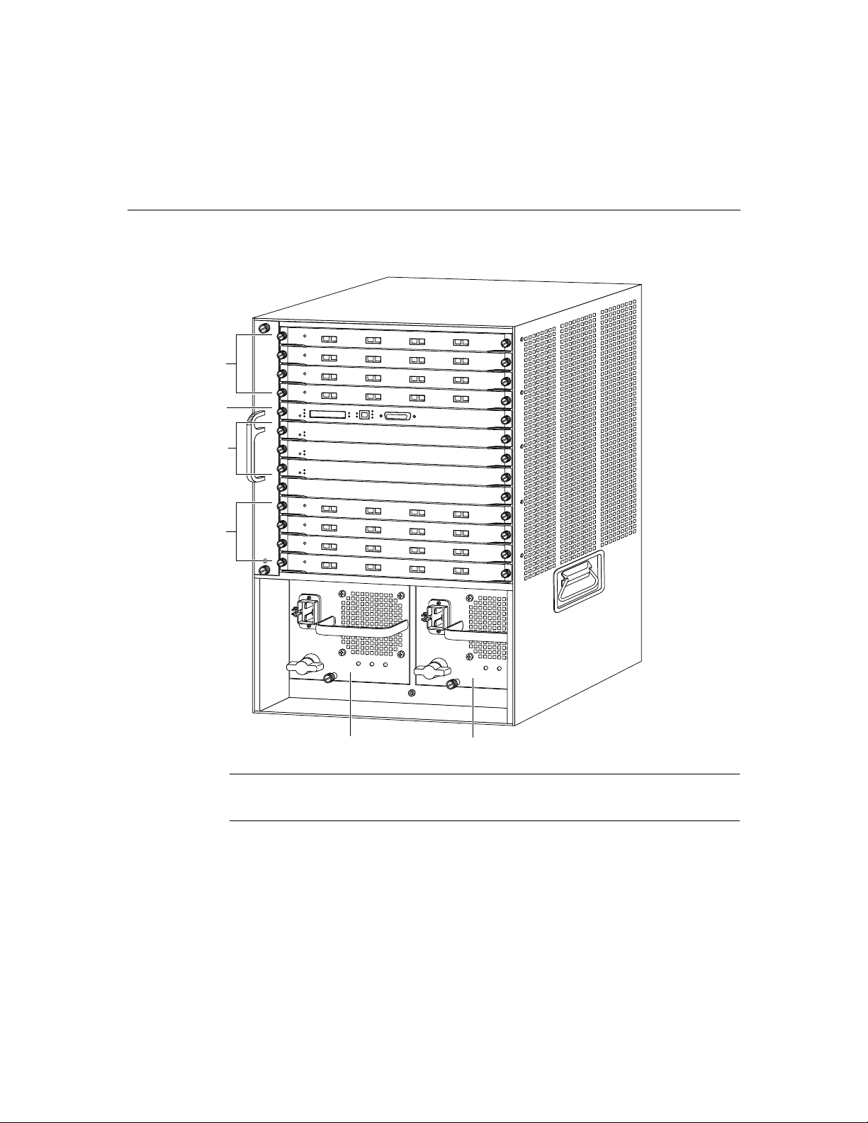
Figure 1-1 Catalyst 8540 Chassis
y
Line modules/
Port adapters
Route processor
Switch modules
Line modules/
Port adapters
16781
1-2
Power suppl
0 Power supply 1
Note The chassis ships populated specific to your order. Figure 1-1 shows an example of
a fully populated chassis.
Catalyst 8540 Chassis Installation Guide
Page 21

Site Planning
This chapter describes how to prepare your site for installation of the chassis and discusses
the site environment requirements. This chapter contains the following sections:
• Site Preparation Guidelines
• Environmental Monitoring Functions
• Site Requirements
Site Preparation Guidelines
Planning the proper location and layout of your equipment rack or wiring closet is essential
for successful system operation. Equipment placed in an inadequately ventilated area can
cause system overtemperature conditions. In addition, poor equipment placement can make
chassis panels inaccessible and difficult to maintain. Follow these precautions when
planning your equipment locations and connections:
CHAPTER
2
• Keep the front of the chassis free from obstructions and away from the exhaust air of
other equipment. Remember that electrical equipment generates heat, and ambient room
temperature alone might not be adequate to cool equipment to acceptable operating
temperatures.
• Secure the placement of all chassis panels, modules, and any module slot fillers. The fan
assembly pulls cooling air across the line modules. A loose panel allows too much air
to escape and can redirect the airflow away from active line modules.
Site Planning 2-1
Page 22

Environmental Monitoring Functions
Warning This unit is intended for installation in restricted access areas. A
restricted access area is where access can only be gained by service personnel
through the use of a special tool, lock and key, or other means of security, and is
controlled by the authority responsible for the location.
Environmental Monitoring Functions
You can maintain normal system operation by identifying and resolving adverse conditions
before the system fails by using environmental monitoring and reporting functions.
Environmental monitoring functions constantly monitor the internal air temperature of the
chassis. Each power supply monitors its own voltage and shuts down if it detects a critical
condition within the power supply. The reporting functions retrieve and display the present
values of measured parameters. If any of the monitored parameters exceed defined
thresholds, the reporting functions display alarms on the console.
The environmental monitoring functions use two levels of status conditions to monitor the
system: normal and alarm. The processor monitors the temperature inside the module
compartment, and the power supplies use the normal and alarm levels to monitor voltages.
Table 2-1 lists temperature thresholds for the processor-monitored levels:
• Normal—All monitored parameters are within normal tolerances.
2-2
• Alarm—An out-of-tolerance temperature or voltage condition exists. The system might
not continue operation. If a voltage measurement reaches this level, the power supply
can shut down the system. Immediate action is required.
Table 2-1 Processor-Monitored Temperature Thresholds
Parameter Normal Alarm
Temperature 0–55°C> 55°C
The power supply monitors its own internal temperature and voltages. The power supply is
either within tolerance (normal) or out of tolerance (alarm). If an internal power supply
temperature or voltage reaches the alarm level, the output fail LED may be unreliable and
the power supply can shut down the system.
Catalyst 8540 Chassis Installation Guide
Page 23

Site Requirements
This section contains the following topics:
• AC and DC Power
• Interference Considerations
• Equipment Racks
• Site Environment
• Equipment Rack Ventilation
• Power
• Network Connections
AC and DC Power
The 1300W AC power supply uses a power factor corrector (PFC) that allows the power
supply to operate on input voltage and current within the ranges of 90 to 264 VAC and 50
to 60 Hz.
A second, identical power supply is also present in the chassis configured with an optional
redundant power supply. Table A-1 in the appendix “Chassis and Power Supply
Specifications” lists system power specifications, including input voltage and operating
frequency ranges.
Site Requirements
The Catalyst 8540 relies on protective devices in the building installation for protection
against short-circuit, overcurrent, and earth fault. Ensure that the protective devices in the
building installation are properly rated to protect the system, and that the protective devices
comply with national and local codes.
Site Planning 2-3
Page 24

Site Requirements
The following warnings apply to DC power supplies:
Warning A readily accessible two-poled disconnect device must be incorporated
in the fixed wiring.
Before connecting each unit, note its power consumption rating in Table A-1 in the
appendix “Chassis and Power Supply Specifications.”
Interference Considerations
When wires are run for any significant distance in an electromagnetic field, interference can
occur between the field and the signals on the wires. As a result:
• Bad plant wiring can result in radio frequency interference (RFI).
• Strong electromagnetic interference (EMI), especially when it is caused by lightning or
radio transmitters, can destroy the signal drivers and receivers in the chassis, and can
even create an electrical hazard by conducting power surges through lines and into
equipment.
Note To predict and remedy strong EMI, you might need to consult RFI experts.
Equipment Racks
A rack-mount kit is provided for mounting the chassis in a standard 19-inch (48 cm)
equipment rack. The rack-mount kit is not suitable for racks with obstructions (such as a
power strip) that could impair access to the processor and power supplies. Figure 2-1 shows
the chassis footprint and outer dimensions.
2-4
Catalyst 8540 Chassis Installation Guide
Page 25
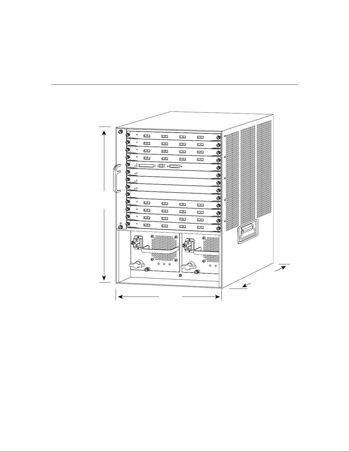
Figure 2-1 Chassis Footprint and Outer Dimensions
25"
(62.5 cm)
Equipment Racks
17104
19.75"
(48.2 cm)
17.75"
(43.13 cm)
To use the rack-mount kit, your equipment rack must meet the following requirements:
• The width of the rack, between the two front mounting strips or rails, must be
17.75 inches (43.13 cm).
• The depth of the rack, between the front and rear mounting strips, must be at least
19.25 inches (48.2 cm) but not more than 32 inches (80 cm).
Site Planning 2-5
Page 26

Site Requirements
• The height of the chassis is approximately 25 inches (62.5 cm). The rack must have
sufficient vertical clearance to allow insertion of the chassis.
When planning your rack installation, follow these guidelines:
• Allow at least 3 feet (1 m) of clearance in front of the rack for maintenance and removal
of the route processor, line modules, power supplies, and the fan assembly.
• Note that the ports for cooling air are located on the front, rear, and both sides of the
chassis, so multiple chassis can be rack-mounted with little or no vertical clearance.
However, avoid placing the chassis in an overly congested rack.
Warning To prevent overheating the chassis, do not operate it in an area that
exceeds the maximum recommended ambient temperature of 104°F (40°C). To
prevent airflow restriction, allow at least 3 inches (7.6 cm) of clearance around the
ventilation openings.
• Consider the equipment and cabling already installed in the rack. Ensure that cables
from other equipment do not obstruct the airflow through the chassis or impair access
to the power supplies or line modules. Route cables away from field-replaceable
components to avoid having to disconnect cables unnecessarily to perform equipment
maintenance or upgrades.
2-6
• Install heavier equipment in the lower half of the rack to maintain a low center of
gravity.
• Ensure that the shelf you place the chassis on can support the weight and dimensions of
the chassis. Use the chassis footprint, shown in Figure 2-1 if you are designing a
customized shelf.
Caution Never install the chassis in an enclosed rack that is not properly
ventilated or air-conditioned.
Catalyst 8540 Chassis Installation Guide
Page 27
Equipment Racks
Follow these guidelines to help ensure your safety:
• Mount the chassis at the bottom of the rack.
• If the rack has stabilizing devices, install the stabilizers before mounting or servicing
the unit in the rack.
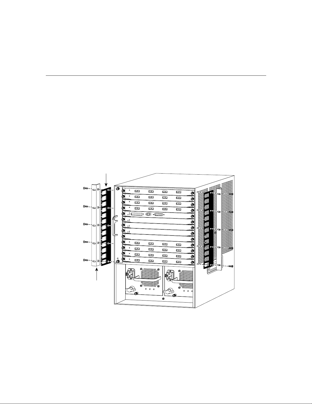
• The chassis must always be mounted horizontally, as shown in Figure 2-2.
In addition to the preceding guidelines, review the precautions in the section “Equipment
Rack Ventilation” later in this chapter.
Figure 2-2 Installing the Chassis in the Rack
Cable
guide
L bracket
17105
Site Planning 2-7
Page 28
Site Requirements
Site Environment
The chassis operates as a standalone system mounted in a rack in a secure wiring closet.
The environment must be dry, clean, well-ventilated, and air-conditioned. An internal fan
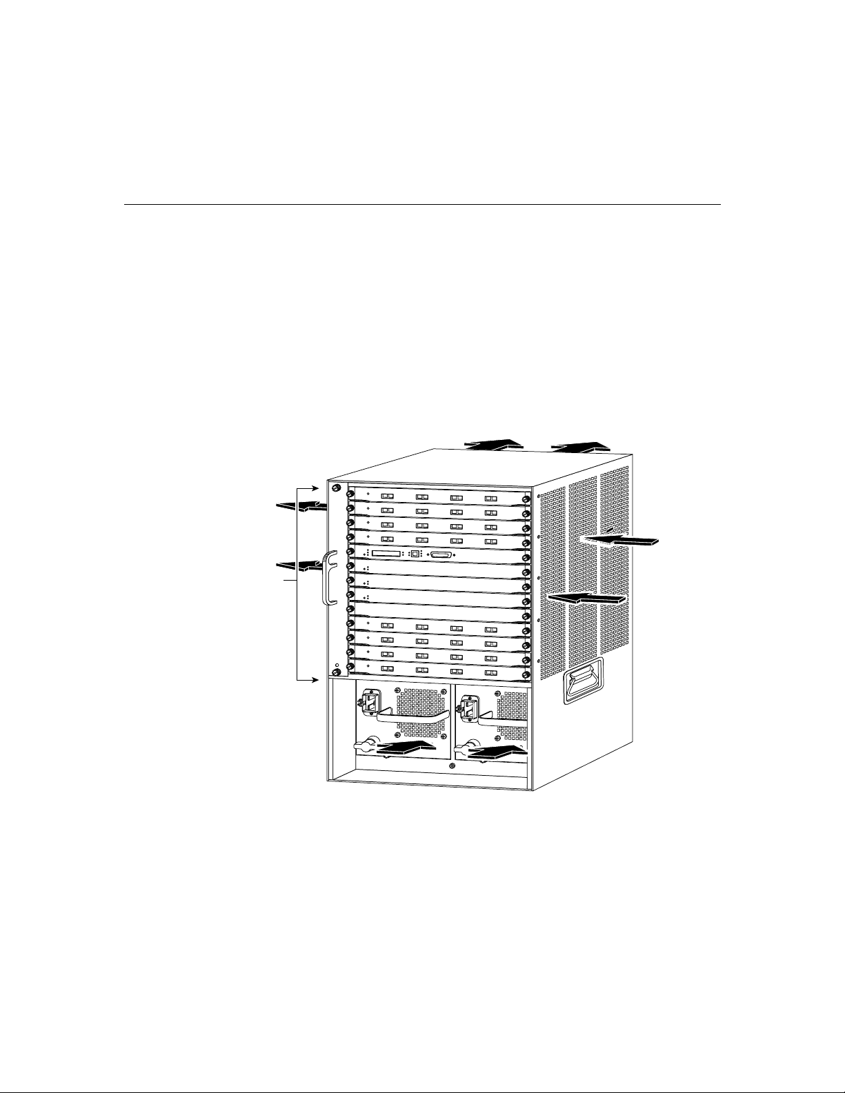
assembly pulls cooling air through the chassis from the front and right side (intake) to the
rear and left side (exhaust). (See Figure 2-3.) The flow of ambient air must be maintained
to ensure normal operation. If the airflow is blocked or restricted, or if the intake air exceeds
104°F, an overtemperature condition can occur. Under extreme conditions, the
environmental monitor can shut down the system to protect the system components.
Figure 2-3 Internal Airflow
Fan
assembly
2-8
17106
To ensure normal operation and avoid unnecessary maintenance, plan your site
configuration and prepare your site before installation. After installation, make sure that the
site maintains an ambient temperature of 32 to 104°F (40°C), and that the area around the
chassis is free of dust.
Catalyst 8540 Chassis Installation Guide
Page 29

Site Environment
If the room temperature exceeds 104°F (40°C), the air temperature inside the chassis could
overheat the unit. Any of the following can inhibit airflow and cause overheating:
• The wiring closet or rack in which the chassis is mounted is not properly ventilated.
• The exhaust of one device is placed so it enters the air intake vent of the chassis.
• The chassis is the top unit in an unventilated rack.
Multiple chassis can be rack-mounted with no clearance above and below the chassis.
When mounting a chassis in a rack with other equipment or when placing a chassis on the
floor adjacent to other equipment, ensure that the exhaust from other equipment does not
blow into the intake vent (lower front panel) of the chassis.
Table 2-2 lists the operating and nonoperating environmental site requirements. To
maintain normal operation and ensure high system availability, maintain an ambient
temperature at your site. The chassis operates in the ranges listed in Table 2-2; however, a
measurement that is approaching the minimum or maximum of a range indicates a potential
problem. You can maintain normal operation by anticipating and correcting environmental
anomalies before they exceed the maximum operating range.
Site Planning 2-9
Page 30

Site Requirements
Table 2-2 Specifications for Operating and Nonoperating Environments
Minimum Maximum
Temperature, ambient operating 32°F (0°C) 104°F (40°C)
Temperature, ambient
nonoperating and storage
Humidity (RH), ambient
(noncondensing) operating
Humidity (RH), ambient
(noncondensing) nonoperating and
storage
Altitude, operating and
nonoperating
Vibration, operating 5 to 200 Hz, 0.5 g
Vibration, nonoperating 5 to 200 Hz, 1 g (1 octet/min)
–4°F (–20°C) 149°F (65°C)
10% 90%
5% 95%
Sea level 6,500 ft. (2000 m)
(1 octet/min)
200 to 500 Hz, 2 g
(1 octet/min)
Equipment Rack Ventilation
If you plan to install the chassis in an equipment rack, follow these precautions and
guidelines that are provided in the section “Equipment Racks” earlier in this chapter to
avoid overtemperature conditions:
• Install the chassis in an enclosed rack only if it has adequate ventilation or an exhaust
fan. Use an open rack whenever possible.
• Note that a ventilation system that is too powerful in a closed rack might prevent cooling
by creating negative pressure around the chassis and redirecting the air away from the
chassis intake vent. If necessary, operate the chassis with the rack open.
• Use baffles inside the enclosed rack to assist in cooling the chassis.
• Do not place equipment near the bottom of a rack, because it might generate excessive
heat that is drawn upward and into the intake ports of equipment above, leading to
overtemperature conditions in the chassis at or near the top of the rack.
2-10
Catalyst 8540 Chassis Installation Guide
Page 31

Power
Follow these precautions when planning power connections to the chassis:
Warning The device is designed to work with TN power systems.
• Install proper grounding to avoid damage from lightning and power surges.
• Connect redundant power supplies to separate input power lines. Install a second source
for redundant power if a separate line is not already in place.
Warning Care must be given to connecting units to the supply circuit so that wiring is not
overloaded.
Network Connections
When preparing your site for network connections to the chassis, consider these factors
related to each type of interface:
• Type of cabling required for each type (fiber-optic, coaxial, or twisted-pair cabling)
Power
• Distance limitations for each signal type
• Specific cables you need to connect each interface
• Any additional interface equipment you need, such as transceivers, modems, channel
service units (CSUs), or data service units (DSUs)
Before installing the chassis, make sure all the additional external equipment and cables are
on hand.
Site Planning 2-11
Page 32

Site Requirements
2-12
Catalyst 8540 Chassis Installation Guide
Page 33

CHAPTER
Installing the Chassis
This chapter describes how to install the chassis, connect the cables, and power up the
chassis at your site. This chapter contains the following sections:
• Safety Recommendations
• Tools for Installation
• Rack-Mounting the Chassis
• System Ground Connection
Caution Before installing the chassis in a rack, read the section “Safety
Recommendations” in this chapter to become familiar with the proper site and
environmental conditions. Failure to read and follow these guidelines can lead to
an unsuccessful installation and possible damage to the system and components.
3
Warning Read the installation instructions before you connect the system to its
power source.
Installing the Chassis 3-1
Page 34

Safety Recommendations
Safety Recommendations
The following guidelines ensure your safety and protect the equipment. This list is not
inclusive of all potentially hazardous situations that you may be exposed to as you install
the chassis, so be alert:
Warning Only trained and qualified personnel should be allowed to install,
replace, or service this equipment.
• Do not lift the chassis by yourself; for safety guidelines to use when lifting, see the
section “Safely Lifting the Chassis.”
• Turn all power supplies off (the position marker should be at zero) and unplug all power
cords before installing or removing a chassis.
• Keep the chassis area clear and free of dust during and after installation.
• Keep tools and chassis components away from walk areas.
• Do not wear loose clothing, jewelry (including rings and chains), or other items that
could get caught in the chassis. Fasten your tie or scarf and sleeves.
3-2
Warning Before working on equipment that is connected to power lines, remove
jewelry (including rings, necklaces, and watches). Metal objects will heat up when
connected to power and ground and can cause serious burns or weld the metal
object to the terminals.
Install the equipment in compliance with the following national codes:
• United States—National Fire Protection Association (NFPA) 70; United States
Electrical Code
• Canada—Canadian Electrical Code, Part I, CSA C22.1
• Other countries—International Electrotechnical Commission (IEC) 364, Parts 1–7 and
any applicable national electrical codes of countries where the product is installed.
Catalyst 8540 Chassis Installation Guide
Page 35

Safely Lifting the Chassis
The chassis weighs 70 pounds (31.7 kg) when empty (no modules or power supplies
installed) and 160 pounds (72.5 kg) with two power supplies and all modules installed. The
chassis is not intended to be moved frequently. Before you install the chassis, verify that
your site is properly prepared to avoid having to move the chassis later to accommodate
power sources and network connections.
Three people are required to lift the chassis. Whenever you lift the chassis or any heavy
object, follow these guidelines:
• Do not lift the chassis by yourself. The size and weight of the chassis requires three
people to safely lift and move it without causing injury and without damaging the
equipment.
• Grasp the bottom of the chassis exterior with both hands.
• Ensure that your footing is solid, and balance the weight of the chassis between your
feet.
• Do not move suddenly or twist your body as you lift. Lift the chassis slowly.
• Keep your back straight and lift with your legs, not your back. If you must bend down
to lift the chassis, bend at the knees, not at the waist, to reduce the strain on your lower
back muscles. (See Figure 3-1.)
Safely Lifting the Chassis
Installing the Chassis 3-3
Page 36

Safety Recommendations
Figure 3-1 Unsafe Lifting Practice
• Leave line modules, power supplies, switch modules, and fan assembly installed.
• Disconnect all external cables before lifting or moving the chassis.
Warning Do not stack the chassis on any other equipment. If the chassis falls, it
can cause severe bodily injury and equipment damage.
H1369a
Ensuring Safety with Electricity
Follow theses guidelines when working with any electrical equipment:
• Locate the emergency off switch for the room in which you are working before
beginning any procedures requiring access to the chassis interior.
• Disconnect all power and external cables before installing or removing a chassis.
• Work with at least one other person when potentially hazardous conditions exist.
• Disconnect the power from a circuit.
3-4
Catalyst 8540 Chassis Installation Guide
Page 37

Preventing Electrostatic Discharge Damage
• Do not perform any action that creates a potential hazard to people or makes the
equipment unsafe.
• Examine your work area for possible hazards such as moist floors, ungrounded power
extension cables, and missing safety grounds.
Warning Never defeat the ground conductor or operate the equipment in the
absence of a suitably installed ground conductor. Contact the appropriate
electrical inspection authority or an electrician if you are uncertain that suitable
grounding is available.
In addition, use the guidelines that follow when working with any equipment that is
disconnected from a power source but still connected to telephone wiring or other network
cabling.
Warning Do not work on the system or connect or disconnect cables during
periods of lightning activity.
• Do not install telephone jacks near water unless the jack is specifically designed for wet
locations.
• Do not touch uninsulated telephone wires or terminals unless the telephone line was
disconnected at the network interface.
• Use caution when installing or modifying telephone lines.
Preventing Electrostatic Discharge Damage
Electrostatic discharge (ESD) damage, which occurs when electronic modules or
components are improperly handled, can result in complete or intermittent failures. The
route processor, switch modules, and line modules each consist of a printed circuit card that
is fixed in a metal carrier. Electromagnetic interference (EMI) shielding and connectors are
integral components of the carrier. Handle the carriers by the carrier edges only; never
touch the modules or connector pins. Although the metal carrier helps to protect the
modules from ESD, use a preventive antistatic strap whenever you handle the route
processor, switch modules, or line modules.
Installing the Chassis 3-5
Page 38

Safety Recommendations
Follow these guidelines to prevent ESD damage:
• Use an ESD-preventive wrist or ankle strap and ensure that it makes good skin contact.
• When removing any module, connect the equipment end of the ESD strap to the ESD
strap connection. (See Figure 3-2.)
• Handle carriers by the faceplates and carrier edges only; avoid touching the card or any
connector pins.
• When removing a module, place the removed module component side up on an
antistatic surface or in a static shielding bag. If the line module is to be returned to the
factory, immediately place it in a static shielding bag.
• Avoid contact between the line modules and clothing. The wrist strap only protects the
card from ESD voltages on the body; ESD voltages on clothing can still cause damage.
For safety, periodically check the resistance value of the antistatic strap. The measurement
should be between 1 and 10 megohms (Mohms).
Figure 3-2 Placement of Electrostatic Discharge Wrist Strap
3-6
16785
ESD
Catalyst 8540 Chassis Installation Guide
Page 39

Tools for Installation
You need the following tools and equipment to install the chassis:
• Number 1 and number 2 Phillips screwdrivers to tighten the captive installation screws
on most systems
• A 3/16-inch flat-blade screwdriver for the captive installation screws on the route
processor and line modules
• An antistatic mat or antistatic foam if you need to remove modules to troubleshoot the
installation
• Your own ESD grounding strap or the disposable ESD strap included with the system
If you are installing the chassis in a rack, you also need the following:
• A rack-mount kit
• A tape measure and a level
Rack-Mounting the Chassis
To install the chassis in a rack, follow these steps:
Tools for Installation
Warning To prevent the chassis from overheating, do not operate it in an area
that exceeds the maximum recommended ambient temperature of 104°F (40°C).
To prevent airflow restriction, allow at least 3 inches (7.6 cm) of clearance around
the ventilation openings.
Step 1 Prepare for installation as follows:
(a) Remove the rubber feet from the chassis, if needed, to ensure a better fit in
the rack. Place the chassis face down on a flat surface. Remove the screw
that holds each foot.
(b) Place the chassis on the floor or on a sturdy table as close as possible to the
rack. Leave enough clearance so that you can move around the chassis.
Installing the Chassis 3-7
Page 40

Rack-Mounting the Chassis
Caution If the rack is on wheels, ensure that the brakes are engaged or that the
rack is otherwise stabilized.
Warning To prevent bodily injury when mounting or servicing this unit in a rack, you
must take special precautions to ensure that the system remains stable. The following
guidelines are provided to ensure your safety:
—This unit should be mounted at the bottom of the rack if it is the only
(c) Use a tape measure to measure the depth of the rack. Measure from the
outside of the front mounting posts to the outside of the rear mounting
strip. The depth must be at least 19.25 inches (48.9 cm) but not greater than
32 inches (81.3 cm).
(d) Measure the space between the inner edges of the left front and right front
mounting posts to ensure that it is 17.75 inches (45.09 cm) wide. (The
chassis is 17.25 inches [43.8 cm] wide and must fit between the mounting
posts.)
(e) Open the rack-mount kit.
unit in the rack.
3-8
—When mounting this unit in a partially filled rack, load the rack from the
bottom to the top with the heaviest component at the bottom of the
rack.
—If the rack is provided with stabilizing devices, install the stabilizers
before mounting or servicing the unit in the rack.
Step 2 Install the shelf brackets as follows:
(a) Position the shelf brackets in the rack. (See Figure 3-3.)
(b) Secure the shelf brackets by using six (three per side) 12 –24 or 10–32
screws.
(c) Attach the crossbar bracket to the back of the shelf brackets using two M3
screws.
Catalyst 8540 Chassis Installation Guide
Page 41

Rack-Mounting the Chassis
Note No shelf is required with this assembly; the shelf brackets support the chassis in the
rack.
Figure 3-3 Installing the Shelf Brackets
Shelf bracket Shelf bracket
12-24 x 3/4-inch
or
10-32 x 3/4-inch screw (6x)
H9466
Step 3 Install the L brackets by attaching the left and right L brackets using the ten M3
Phillips countersunk-head screws provided in the rack-mount kit.
(See Figure 3-4.)
Note Some equipment racks provide a power strip along the length of one of
the rear posts. If your rack has this feature, consider the position of the strip
when planning fastener points. Before you install the L brackets on the chassis,
determine whether you will install the chassis from the front or the rear of the
rack.
Installing the Chassis 3-9
Page 42

Rack-Mounting the Chassis
Figure 3-4 Attaching L Brackets and Cable Guides
Fan
assembly
Note If you are installing cable guides, place the cable guides inside the L
brackets, between the L bracket and the chassis. Secure the cable guides to the
chassis using the same screws (and chassis holes) as the L brackets. (See
Figure 3-4.) The cable guides and screws are provided in the cable management
kit.
3-10
17106
Catalyst 8540 Chassis Installation Guide
Page 43

Rack-Mounting the Chassis
Step 4 Install the chassis in the rack as follows:
Warning Three people are required to lift the chassis. Grasp the chassis
underneath the lower edge and lift with both hands. To prevent injury, keep your
back straight and lift with your legs, not your back. To prevent damage to the
chassis and components, never attempt to lift the chassis with the handles on the
power supplies or on the interface processors, or by the plastic panels on the front
of the chassis. These handles were not designed to support the weight of the
chassis.
(a) With one person standing at each side of the chassis, grasp the bottom edge
of the chassis with one hand near the front and the other near the back.
Slowly lift the chassis in unison. To prevent injury, avoid sudden twists or
moves.
(b) Position the chassis in the rack as follows (see Figure 3-5):
If the front of the chassis (front panel) is at the front of the rack, insert the
rear of the chassis between the mounting posts.
If the rear of the chassis is at the front of the rack, insert the front of the
chassis between the mounting posts.
(c) Place the chassis on the shelf brackets.
(d) Align the mounting holes in the L bracket with the mounting holes in the
equipment rack.
(e) A third person should install the ten (five per side) 12–24 or 10–32 screws
through the elongated holes in the L bracket and into the threaded holes in
the mounting post.
(f) Use a tape measure and level to ensure that the chassis is installed straight
and level.
Step 5 Check the release levers to ensure that all modules are installed securely.
Step 6 Tighten any loose captive installation screws on all modules.
Installing the Chassis 3-11
Page 44

Rack-Mounting the Chassis
Figure 3-5 Installing the Chassis in the Rack
t
3-12
Crossbar bracket
Catalyst 8540 Chassis Installation Guide
H9467
Shelf bracket
Page 45

System Ground Connection
Note The system ground connection must be connected to a suitable ground. The power
supply ground connection must also be connected to a suitable ground.
This section describes how to connect a system (earth) ground to the switch. Two
grounding holes are provided on the chassis frame for the grounding hole location. See
Figure 3-6.
Note The earth ground should be used on both AC- and DC-powered systems.
Required Tools and Equipment
To connect the switch to an earth ground, you need the following tools and materials:
Note Materials are not provided; contact any commercial cable vendor for the required
parts.
System Ground Connection
• Grounding lug—The grounding lug must have two M4 screw holes.
• Two M4 (metric) hex-head screws with locking washers.
• One grounding wire—The length and size of the grounding wires depends on the
proximity of the switch to proper grounding facilities, national and local ones.
• Number 2 Phillips head screwdriver.
• Crimping/wire-stripping tool.
Installing the Chassis 3-13
Page 46

System Ground Connection
Figure 3-6 System Ground Location
F
A
S
F
A
S
U
T
U
T
T E
T
H
E
R
T
E
T
H
E
R
SWITCH/PROCESSOR
SWITCH/PROCESSOR
C
8
5
M
RO
UTE
OC3/STM1 M
P
P
G
I
G
A
B
I
T
E
T
H
E
R
N
E
T
1
6K
LL-
FU
RX
DUPLEX
CDM
T
TX
OP-DE
RX-SEC
OC
T-1
2 A
TM SMF
-IR
256
k
X
M
T
R
A
L
A
X
R
D
/
X
T
X
R
C
S
1
2
TU
STA
N
E
T S
W
IT
C
H
IN
G
M
O
D
U
L
E
1
STATUS
N
E
T
S
W
I
T
C
H
I
N
G
M
O
D
U
L
E
FAN
PS2
STATUS
S1
P
AN
F
S2
P
STATUS
S1
P
S
-1
8F
-O
C
3
M
M
TX
X
STATUS
R
K
SW
IT
IN
CH MO
DULE
L
1
M
F
0
TX
TX
RX
RX
UTP3
0
TX
TX
TX
RX
RX
RX
UTP3
UTP3
4
3
4
5
2
3
3
4
5
X
T 2
T
O
SL
ESET
R
SLOT 2
RX
T 1
LO
K
S
OT 1
LIN
SL
t
IA
ne
C
E
M
PC
X
T
SET
E
R
LOT 2
S
X
R
OT 1
L
LINK
S
IA
net
C
E
CM
X
T
X
R
K
IN
L
1
UTP3
1
UTP3
P
X
T
X
T
X
T
X
T
X
T
X
R
K
IN
2
L
3
X
T
X
X
R
X
R
X
R
X
R
K
R
K
IN
K
L
IN
4
K
L
IN
5
K
L
IN
6
L
7
LIN
2
3
TX
TX
RX
RX
UTP3
UTP3
2
3
TX
TX
RX
RX
UTP3
UTP3
LEX
G
IG
A
B
IT
E
T
H
E
R
N
E
T
16
K
FULL
RX
DM
DUP
C
TX
OP-DET
RX-SEC
GGIGA
BIT EHT
ERN
ET 16
K
FULL-
LINK
DUPLEX
RX
OP-DET
RX-SYNC
TX
X
T
X
R
6
7
8
9
10
11
12
6
7
8
9
10
11
12
UX
A
T
EJEC
UX
A
T
JEC
E
X
T
TX
X
T
X
T
X
T
X
R
K
IN
8
9
L
TX
RX
U
T
P
U
T
P
TX
RX
U
T
P
U
T
P
X
T
X
R
K
LIN
1
0
0
UTP3
0
UTP3
X
X
T
X
R
K
IN
1
L
1
1
TX
RX
UTP3
1
TX
RX
UTP3
T
X
R
K
IN
1
2
L
X
T
X
X
R
X
R
X
R
X
R
K
R
K
IN
K
L
IN
1
3
K
L
1
4
K
IN
LIN
1
5
L
IN
1
6
L
2
3
TX
TX
RX
RX
UTP3
UTP3
2
3
TX
TX
RX
RX
UTP3
UTP3
3-14
IN
P
U
T
IN
P
U
T
O
K
O
K
Grounding
pad
Wire
Grounding lug
Screws (M4)
Catalyst 8540 Chassis Installation Guide
F
A
N
O
U
T
P
U
T
F
A
N
O
U
T
P
U
T
O
K
F
A
IL
O
K
F
A
IL
IN
P
U
T
F
A
N
O
U
T
P
U
T
O
K
O
K
F
A
IL
45787
Grounding
pad location
Page 47

Connecting the System to the Grounding Pad
Connecting the System to the Grounding Pad
You must complete this procedure before connecting the system power or turning on the
switch.
To attach the grounding lug and cable to the grounding pad, perform these steps:
Step 1 Use a wire-stripping tool to remove approximately 0.75 inch (19 mm) of the
covering from the end of the grounding wire.
Step 2 Insert the stripped end of the grounding wire into the open end of the grounding
lug.
Step 3 Use a crimping tool to secure the grounding wire in place in the grounding lug.
Step 4 Locate the grounding pad on the switch (See Figure 3-6.).
Step 5 Remove the label that covers the grounding pad.
Step 6 Place the grounding lug against the grounding pad.
Step 7 Insert two screws through the holes in the grounding lug and the grounding pad.
Ensure that the grounding lug will not interfere with other switch hardware or
rack equipment.
Step 8 Install the locking washers and nuts; tighten them to secure the grounding lug to
the grounding pad.
Step 9 Prepare the other end of the grounding wire and connect it to an appropriate
grounding point in your site to ensure adequate earth ground for the switch.
Installing the Power Supplies
As your communication requirements change, you might want to upgrade your system and
add or replace a power supply.
You need the following tools to remove and install a power supply:
• A 1/4-inch flat-blade screwdriver to remove and install filler plates and to loosen or
tighten the captive installation screw on the power supply.
• Filler plates to install over empty power supply bays to protect the connectors
from contamination.
Installing the Chassis 3-15
Page 48

System Ground Connection
To install an AC-input or DC-input power supply, follow these steps:
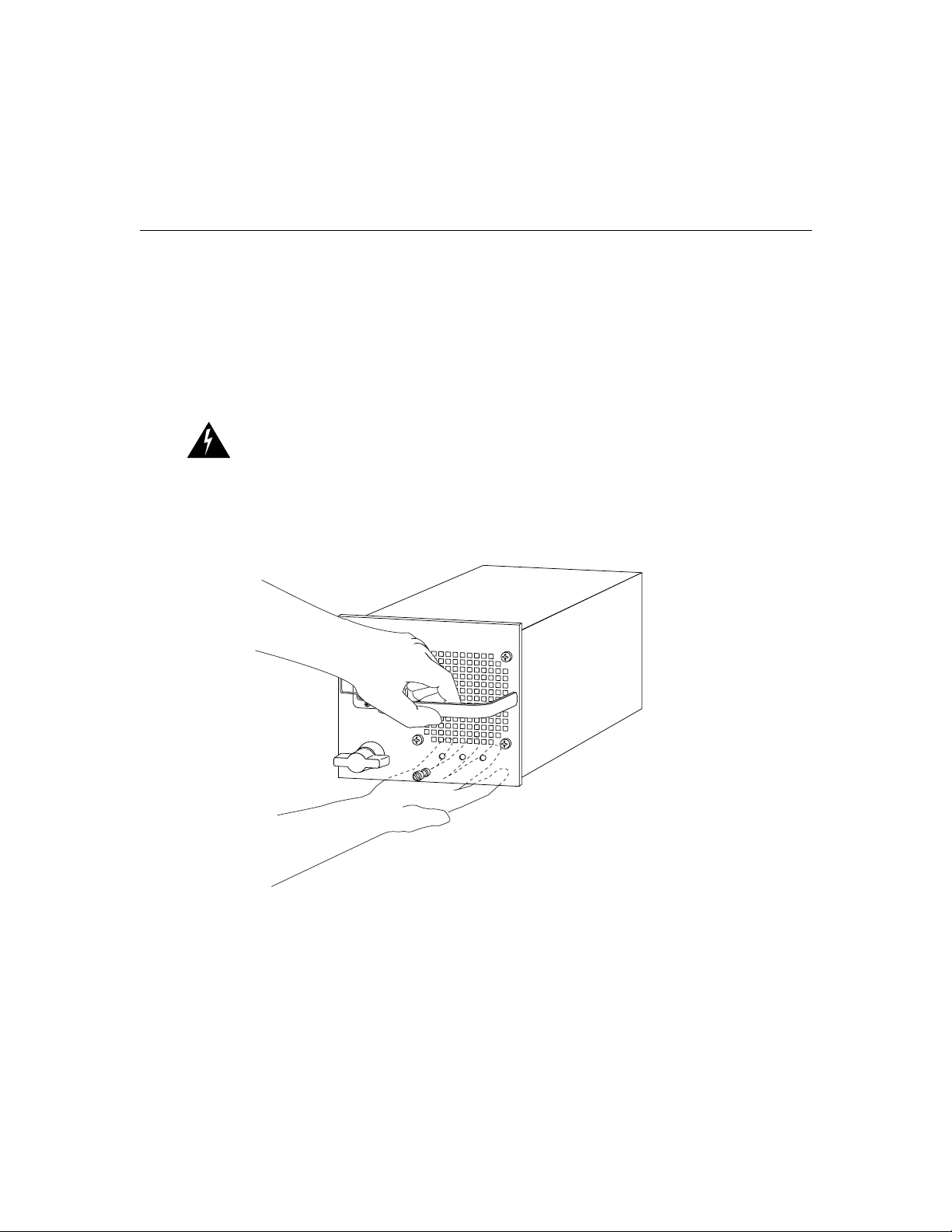
Warning Voltage is present on the backplane when the system is operating. To
reduce risk of an electric shock, keep hands and fingers out of the power supply
bays and backplane areas.
Step 1 Grasp the power supply handle with one hand. Place your other hand underneath
Step 2 Place the power supply into the power supply bay and push the power supply
Step 3 Tighten the captive installation screw by turning it clockwise.
For detailed power supply installation, removal, and maintenance information, see the
section “Removing and Installing Power Supplies” in the chapter
“Maintaining the Chassis.”
Figure 3-7 Handling a Power Supply
to support the bottom of the supply, as shown in Figure 3-7.
into the bay until the power supply faceplate is flush with the cover.
3-16
14305
Catalyst 8540 Chassis Installation Guide
Page 49

Confirming the Installation
If your system has problems starting up, use the information in this section to help isolate
the cause. Problems with the initial startup are usually caused by an interface processor or
power supply that has become dislodged from the backplane or chassis power connector.
Although overtemperature conditions rarely occur at initial startup, the environmental
monitoring functions are included because they also monitor DC line voltages. This
publication covers the system hardware installation only. At the initial system boot, you
should verify the following:
• The power supplies are installed properly and are supplying power to the system.
• The system fan assembly is operating.
• The system software boots successfully.
• The route processor, switch modules, and line modules are properly installed in their
slots and each is initialized without problems.
When all of these conditions are met, the hardware installation is complete and you can
begin software configuration of the Catalyst 8540 route processor. Refer to the following
publications for detailed software configuration information:
• Catalyst 8540 Campus Switch Router Software Feature and Configuration Guide
Confirming the Installation
• Catalyst 8540 MSR Software Configuration Guide
If you are unable to easily solve the problem, contact a customer service representative for
assistance and further instructions. To help your service provider assist you, gather the
following information before you call:
• The date you received the chassis
• The chassis serial number (located on a label on the front of the chassis)
• The type of software and release number
• A brief description of the problem
• A brief explanation of the steps already taken to isolate and resolve the problem
• The maintenance agreement or warranty information
Installing the Chassis 3-17
Page 50

System Ground Connection
3-18
Catalyst 8540 Chassis Installation Guide
Page 51

CHAPTER
4
Maintaining the Chassis
This chapter describes how to add and replace internal system components such as system
fan assemblies and power supplies for the chassis.
Your chassis is configured as specified in your order and is ready for installation and startup
when it leaves the factory. As your communication requirements change, you can upgrade
your system, add components, or change the initial configuration. Software and component
upgrades require specific documents and other frequently updated information; therefore,
only basic replacement guidelines are included in this publication.
There are two kinds of replaceable system components: those that support hot swapping
and those that require the system power to be shut down before they are replaced.
Redundant power supplies, line modules, and the fan assembly are hot swappable.
This chapter contains the following sections:
• Removing and Installing Power Supplies
• Replacing the Chassis Fan Assembly
Warning Ultimate disposal of this product should be handled according to all
national laws and regulations.
Maintaining the Chassis 4-1
Page 52

Removing and Installing Power Supplies
Removing and Installing Power Supplies
As your communication requirements change, you might want to upgrade your system and
add or replace a power supply. This section contains the following power supply
information:
• Power Supply LEDs
• Overvoltage and Overtemperature Protection
• Removing and Installing AC-Input Power Supplies
• Removing and Installing DC-Input Power Supplies
Power Supply LEDs
The three LEDs (see Figure 4-1) on the power supply indicate the status of the power
supply. The Input OK LED indicates that the power supply is on and receiving source
power. The Fan OK signal indicates that the fan assembly is operating properly. The Output
Fail LED is lit only when output voltage is outside of proper range,+3.3, +5, +12, and
+42 VDC.
4-2
Figure 4-1 Power Supply
Power
Metal prongs
Cable
retention
clip
Power
switch
connection
Captive screw
Catalyst 8540 Chassis Installation Guide
INPUT
16787
FAN
OUTPUT
O
K
OK
FAIL
Page 53

Overvoltage and Overtemperature Protection
Overvoltage and Overtemperature Protection
The power supply monitors its own temperature and internal voltages. If the power supply
detects an overvoltage or overtemperature condition, it shuts down to avoid damage to the
power supply or other system components.
Note If the power supply shuts down, turn the power switch off (0), wait several minutes
for the supply to cool, and then turn the power switch on ( | ). If the power supply shuts
down again, remove and replace it.
Removing and Installing AC-Input Power Supplies
The redundant 1300W power supplies (AC-input) support hot swapping. When two power
supplies are installed, you can remove or install one supply without affecting system
operation. When power is removed from one supply, the redundant power feature causes
the second supply to ramp up to full power and maintain uninterrupted system operation.
In systems with dual power supplies, connect each power supply to separate input lines so
that, in case of a line failure, the second source is available and can maintain uninterrupted
power to the system.
A 20A modular power cord should connect each AC-input power supply to a separate site
power source.
Note Each AC-input power supply weighs 22 pounds.
Caution Use both hands to remove and install power supplies.
Maintaining the Chassis 4-3
Page 54

Removing and Installing Power Supplies
Tools Required
You need the following tools to remove and install a power supply:
• A 1/4-inch flat-blade screwdriver to remove and install filler plates and to loosen or
tighten the captive installation screw on the power supply.
• Filler plates to install over empty power supply bays to protect the connectors
from contamination.
Removing AC-Input Power Supplies
To remove an AC-input power supply, follow these steps:
Step 1 Turn off the power switch on the power supply you are removing.
(See Figure 4-2.)
Caution Failure to turn off the AC-input power supply could result in equipment
damage.
Figure 4-2 AC-Input Power Supply Switch, AC Connection, and Captive Screws
Power
Metal prongs
connection
4-4
Cable
retention
clip
Power
switch
Captive screw
Catalyst 8540 Chassis Installation Guide
INPUT
OK
16787
FAN
OUTPUT
OK
FAIL
Page 55

Removing and Installing AC-Input Power Supplies
Step 2 Disconnect the AC power cord from the power source.
Step 3 Remove the input power cord from the power inlet.
Warning Before working on a system that has an on/off switch, turn off the
power and unplug the power cord.
Step 4 Loosen the captive installation screw on the power supply with a screwdriver.
(See Figure 4-2.)
Step 5 Grasp the power supply handle with one hand. Slowly pull the power supply out
of the chassis toward you. (See Figure 4-3.)
Warning Voltage is present on the backplane when the system is operating. To
reduce risk of an electric shock, keep hands and fingers out of the power supply
bays and backplane areas.
Figure 4-3 Power Supply Removal and Installation
16788
Maintaining the Chassis 4-5
Page 56
Removing and Installing Power Supplies
Step 6 While holding the power supply handle with one hand, place your other hand
underneath to support the bottom of the supply, as shown in Figure 4-4.
Step 7 Pull the power supply out of the bay and put it aside.
Step 8 If the power supply bay is to remain empty, install a filler plate over the opening
and secure it with the mounting screws.
Warning Blank faceplates and cover panels serve three important functions: they
prevent exposure to hazardous voltages and currents inside the chassis; they
contain electromagnetic interference (EMI) that might disrupt other equipment;
and they direct the flow of cooling air through the chassis. Do not operate the
system unless all cards, faceplates, front covers, and rear covers are in place.
Figure 4-4 Handling an AC-Input Power Supply
4-6
16748
Catalyst 8540 Chassis Installation Guide
Page 57

Installing the AC-Input Power Supply
To install an AC-input power supply, follow these steps:
Step 1 Grasp the power supply handle with one hand. Place your other hand underneath
to support the bottom of the supply, as shown in Figure 4-4.
Step 2 Place the power supply into the power supply bay and push the power supply
into the bay until the power supply faceplate is flush with the cover.
Warning Voltage is present on the backplane when the system is operating. To
reduce risk of an electric shock, keep hands and fingers out of the power supply
bays and backplane areas.
Step 3 Tighten the captive installation screw by turning it clockwise.
Connecting the AC-Input Power Supply
Connect an AC-input power supply as follows:
Step 1 Plug a power cord into the power inlet of one AC-input power supply.
(See Figure 4-5.)
Removing and Installing AC-Input Power Supplies
Step 2 Connect the other end of the AC-input power supply cord to an input line.
Warning The plug-socket combination must be accessible at all times because it
serves as the main disconnecting device.
To complete the installation, see the section “Power Cord Connections.”
Connecting Redundant AC-Input Power Supply
Connect the redundant AC-input power supply to a separate input line as follows:
Step 1 Plug in the power cord on the redundant AC power supply. (See Figure 4-5.)
Step 2 Connect the redundant power supply cord to an input line other than the initial
power supply line.
Maintaining the Chassis 4-7
Page 58

Removing and Installing Power Supplies
Figure 4-5 Power Cord Connections
4-8
IN
PU
T
FA
N
O
UTP
UT
IN
PU
T
FA
N
OK
O
U
TP
U
T
O
K
FAIL
O
K
O
K
FA
IL
Power
supply 0
Power
cord
connection
connection
Catalyst 8540 Chassis Installation Guide
Power
cord
IN
PU
O
K
Power
supply 1
T
FA
N
O
U
TP
U
T
O
K
FAIL
16789
Page 59

Removing and Installing DC-Input Power Supplies
Powering Up the AC-Input Power Supply
Perform these steps to power up the AC-input power supply and confirm the installation:
Step 1 Turn the power switch of the AC-input power supply on ( | ).
Step 2 Verify that the LEDs (See Figure 4-1.) on the front panel of the power supply are
in the following state within 5 seconds of operation:
• Input OK: ON
• Fan OK: ON
• Output Fail: OFF
Removing and Installing DC-Input Power Supplies
The redundant DC power supplies support hot swapping. When two power supplies are
installed, you can install, remove, or replace one supply without affecting system operation.
When power is removed from one supply, the redundant power feature causes the second
supply to ramp up to full power and maintain uninterrupted system operation. In systems
with dual power supplies, connect each power supply to separate DC-input lines; in the
event of a line failure, the second source is still available.
The DC-input power supply is required by many telcos because these installations are
powered by -48 or -60 VDC batteries. From an operational perspective, the DC-input
power supply has the same characteristics as the AC-input version.
Figure 4-6 shows the location of the DC-input power supplies in a redundant configuration.
In a nonredundant configuration, the power supply goes in the slot labeled Power Supply 0.
Maintaining the Chassis 4-9
Page 60

Removing and Installing Power Supplies
Figure 4-6 DC-Input Power Supply Location
o
INP
UT
OK
FAIL
O
K
Power supply 0
o
Power supply 1
Removing the DC-Input Power Supply
To remove a DC-input power supply, follow these steps:
Step 1 Verify that the power is off to the DC circuit furnishing power to the power
supply you are removing.
Warning Before connecting or disconnecting ground or power wires to the
chassis, ensure that power is removed from the DC circuit. To ensure that all
power is OFF, locate the circuit breaker on the panel board that services the DC
circuit, switch the circuit breaker to the OFF position, and tape the switch handle
of the circuit breaker in the OFF position.
INP
UT
OK
FAIL
OK
16609
4-10
Catalyst 8540 Chassis Installation Guide
Page 61

Removing and Installing DC-Input Power Supplies
Step 2 Turn off the power switch on the power supply you are removing. (See
Figure 4-7.)
Step 3 Remove the terminal block cover by removing the two screws at the top and
bottom of the terminal block. (See Figure 4-7.)
Step 4 Disconnect the input wires from the terminal block. (See Figure 4-7.)
Figure 4-7 DC-Input Power Supply
Terminal
block
cover
Power
switch
o
INPUT
FAN
OUTPUT
OK
OK
FAIL
17116
LEDs
Captive screw
Warning
When installing the unit, the ground connection must always be made
first and disconnected last.
Step 5 Loosen and remove the captive screw on the power supply with a screwdriver.
Step 6 Grasp the power supply handle with one hand. Slowly pull the power supply out
of the chassis toward you. (See Figure 4-3.)
Step 7 While holding the power supply handle with one hand, place your other hand
underneath to support the bottom of the supply.(See Figure 4-8.)
Maintaining the Chassis 4-11
Page 62

Removing and Installing Power Supplies
Figure 4-8 Handling a DC-Input Power Supply
o
14307
DC
FAN
OUTPUT
OK
OK
FAIL
4-12
Step 8
If the power supply bay is to remain empty, install a power supply filler plate
over the opening and secure it with the mounting screws. This protects the inner
chassis from dust and prevents accidental contact with live voltage at the rear of
the bay.
Warning Voltage is present on the backplane when the system is operating. To
reduce risk of an electric shock, keep hands and fingers out of the power supply
bays and backplane areas.
Catalyst 8540 Chassis Installation Guide
Page 63

Installing the DC-Input Power Supply
To install a DC-input power supply, follow these steps:
Step 1 Verify that power is off to the DC-input circuit.
Warning Before connecting or disconnecting ground or power wires to the
chassis, ensure that power is removed from the DC circuit. To ensure that all
power is OFF, locate the circuit breaker on the panel board that services the DC
circuit, switch the circuit breaker to the OFF position, and tape the switch handle
of the circuit breaker in the OFF position.
Step 2 Grasp the power supply handle with one hand and place your other hand
underneath to support the bottom of the supply, as shown in Figure 4-8.
Step 3 Place the DC-input power supply into the power supply bay and push the
DC-input power supply into the bay until the power supply faceplate is flush
with the cover.
Warning Voltage is present on the backplane when the system is operating. To
reduce risk of an electric shock, keep hands and fingers out of the power supply
bays and backplane areas.
Removing and Installing DC-Input Power Supplies
Step 4 Tighten the captive installation screw by turning it clockwise. (See Figure 4-7)
Connecting the DC-Input Power Supply
To connect the DC-input power supply to the input voltage source, follow these steps:
Step 1 Verify that power is off to the input circuit.
Warning Before performing any of the following procedures, ensure that power
is removed from the DC circuit. To ensure that all power is OFF, locate the circuit
breaker on the panel board that services the DC circuit, switch the circuit breaker
to the OFF position, and tape the switch handle of the circuit breaker in the OFF
position.
Maintaining the Chassis 4-13
Page 64
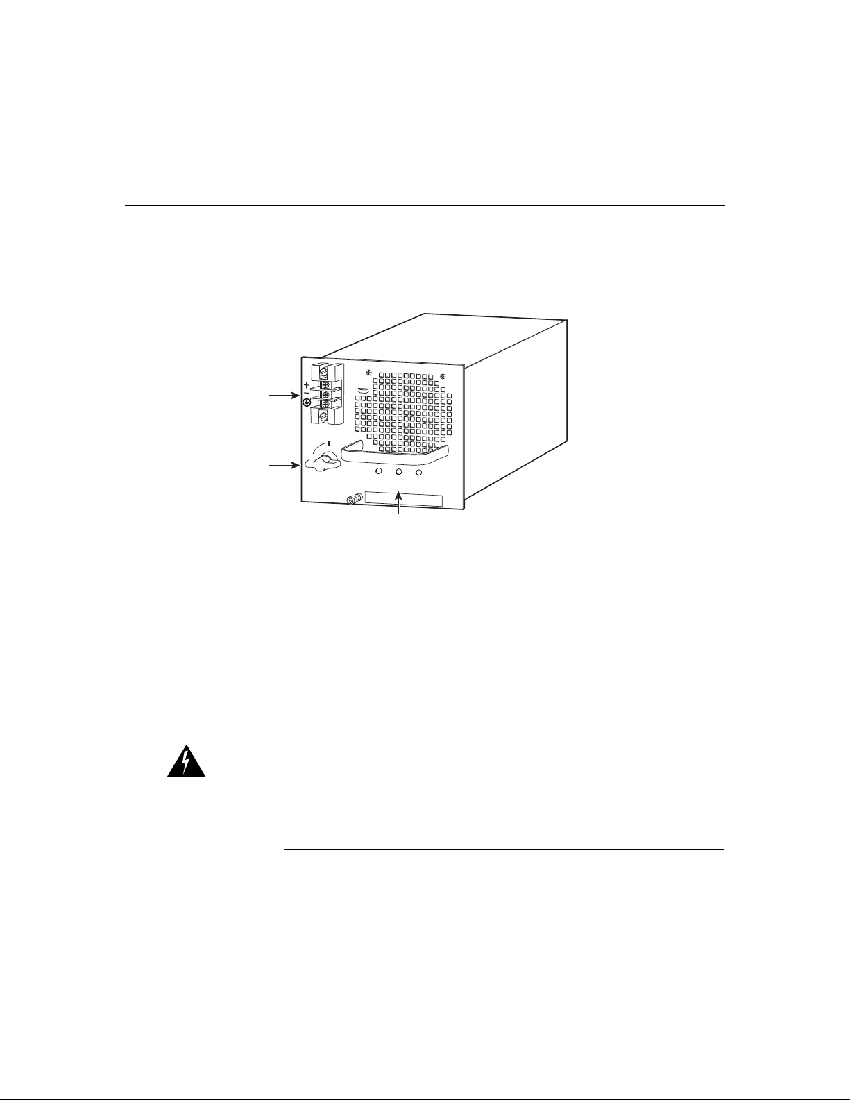
Removing and Installing Power Supplies
Step 2 Ensure that the power switch is off (0) on the power supply. (See Figure 4-9.)
Figure 4-9 Power Switch and Terminal Block Connections
Terminal
block
Power
switch
o
INPUT
FAN
OUTPUT
OK
OK
FAIL
15708
LEDs
Step 3
Remove the terminal block cover by removing the two screws at the top and
bottom of the terminal block cover.
Step 4 Attach the appropriate lugs to the DC-input wires.
Step 5 From the top of the terminal block, wire the DC-input conductors to the terminal
block as follows:
• Ground wire to ground terminal
• Return wire to “+” terminal
• Battery wire to “−” terminal
Warning When installing the unit, the ground connection must always be made
first and disconnected last.
Note Be sure to route the wires from the top of the terminal block so that you
do not obstruct access to the chassis power switch.
4-14
Catalyst 8540 Chassis Installation Guide
Page 65

Step 6 After ensuring that all wire connections are secure, reinstall the terminal block
cover.
To complete the installation, see the section “Powering Up the DC-Input Power Supply”
in this chapter.
Connecting the Redundant DC-Input Power Supply
To connect the redundant DC-input power supply to a separate input line, repeat the steps
in the previous section, “Connecting the DC-Input Power Supply,” but connect the
redundant unit to a different DC-input line from the initial power supply.
Powering Up the DC-Input Power Supply
To power up the DC power supply and confirm the installation, follow these steps:
Step 1 Remove the tape from the circuit breaker switch handle.
Step 2 Turn the power supply power switch on (|).
Step 3 Verify that the Input OK and Fan OK LEDs on the power supply front panel is
green. (See Figure 4-7.)
Replacing the Chassis Fan Assembly
Replacing the Chassis Fan Assembly
This section describes how to replace the fan assembly, which is a single unit that draws in
cooling air and distributes it across the route processor, switch modules and line modules.
Caution Before performing any procedures in this chapter, review the sections
“Safety Recommendations,” “Ensuring Safety with Electricity,” and “Preventing
Electrostatic Discharge Damage” in the chapter “Installing the Chassis.”
Caution If you are replacing the fan assembly while the unit is operating, make
sure the replacement fan assembly is ready to be installed immediately.
Maintaining the Chassis 4-15
Page 66

Replacing the Chassis Fan Assembly
The chassis fan assembly draws cooling air in through the front right side of the chassis and
exhausts the air through the back left side to cool the processor and line modules. The
absence of cooling air can cause the interior of the chassis to heat up and can cause an
overtemperature condition. Never operate the system if the fan assembly is not
functioning properly.
The fan assembly is located at the left of the chassis module cage. (See Figure 4-10.) The
fan assembly is secured to the back panel with two captive installation screws.
Caution Never operate the system if the fan assembly is not functioning
properly or if one is not reinstalled quickly. An overtemperature condition can
result in severe equipment damage.
Figure 4-10 Chassis Fan Assembly
4-16
Fan
assembly
17106
Catalyst 8540 Chassis Installation Guide
Page 67

Tools Required
You need a 3/16-inch flat-blade screwdriver to remove the fan assembly.
Removing the Fan Assembly
To remove the existing chassis fan assembly, follow these steps:
Step 1 Locate the fan assembly (see Figure 4-10) at the left of the module cage, above
the power supply.
Step 2 Use a flat-blade screwdriver to loosen each of the two captive installation screws
by turning them counterclockwise.
Step 3 Loosen both screws on the chassis. These captive installation screws are fixed
to the fan assembly; do not attempt to completely remove them.
Step 4 Grasp the fan assembly with both hands and pull it toward you and away from
the backplane using steady pressure until it frees the backplane.
Step 5 Lift the fan assembly out of the chassis and place it in a safe place.
If the power has not been turned off, quickly proceed to the following section to reinstall a
fan assembly.
Replacing the Chassis Fan Assembly
Caution Never operate the system if the fan assembly is not functioning
properly or if a fan assembly is not quickly reinstalled. An overtemperature
condition can result in severe equipment damage.
Installing a New Fan Assembly
To install the new fan assembly, follow these steps:
Step 1 Hold the fan assembly with the fans facing to the right.
Step 2 Place the fan assembly into the front chassis cavity so it rests on the chassis, and
then lift the fan assembly up slightly and align the top and bottom guides.
Step 3 Push the fan assembly into the chassis until the captive installation screws meet
the chassis.
Step 4 Tighten each of the two captive installation screws.
Maintaining the Chassis 4-17
Page 68

Replacing the Chassis Fan Assembly
4-18
Catalyst 8540 Chassis Installation Guide
Page 69

APPENDIX
Chassis and Power Supply
Specifications
The chassis and power supply specifications are described in Table A-1.
A
Table A-1 Chassis and Power Supply Specifications
Description Specifications
Dimensions (H x W x D) 25 x 17.75 x 19.75 in. (62.5 x 43.13 x 48.2cm)
Weight Chassis only: 70 lb (31.7 kg)
Airflow 200 lfm1 through the system fan assembly
Operating temperature 32 to 104°F (0 to 40°C)
Nonoperating temperature –40 to 167°F (–40 to 75°C)
Humidity 10 to 90%, noncondensing
Altitude –500 to 6,500 ft. (–52 to 2,000 m)
Mean time between
failures
Compliance CE Marking
Safety UL
Chassis depth including cable guide: 21.64 in. (55.0 cm)
Power supply: 7.9 x 7.1 x 15.3 in. (20.1 x 18.1 x 38.9 cm)
Chassis fully configured with 2 route processors, 8 line modules, 3 switch modules, and
2 power supplies:160 lb (72.5 kg)
AC power supply: 22 lb
DC power supply: 25 lb
7.1 years for system configuration
2
1950, CSA3 -C22.2 No. 950, EN4 60950, IEC5 950, TS6 001, AS/NZS7 3260
Chassis and Power Supply Specifications A-1
Page 70

Table A-1 Chassis and Power Supply Specifications (continued)
Description Specifications
9
EMI8,
FCC10 Part 15 Class A (CFR 47), ICES11-003 Class A, EN 55022 Class A,
CISPR22 Class A, AS/NZS 3548 Class A, and VCCI
12
Class A with UTP13 cables
EN 55022 Class B; CISPR22 Class B, AS/NZS 3548 Class B, and VCCI Class B with
FTP14 cables
AC Power Supply Specifications
AC total output 1300W maximum
AC-input voltage 100 to 240 V wide input with power factor correction
AC frequency 50 to 60 Hz
Power supply load 1300W maximum configuration, 1000W typical with maximum configuration
AC current Rated 16 to 8A
Maximum power budget: 17.6A @ 100 VAC, 60 Hz
14.6A @ 115 VAC, 60 Hz; 7A @ 230 VAC, 50 Hz with chassis fully configured
AC voltages supplied and
steady-state maximum
current ratings
+3V3 @ 15.0A
+5V @ 5.0A
+12V @ 6.0A
+42V @ 27.46A
Heat dissipation 1760W (6000 Btu
15
/hr)
DC Power Supply Specifications
DC total output 1360W maximum
Power supply load 1360W maximum, 1000W typical with maximum configuration
DC input current Rated 40A
Maximum power draw: 43A @ 42 VDC, 38A @ 48 VDC, 30A @ 60 VDC with chassis
fully configured
DC voltages supplied and
steady-state maximum
current ratings
+3V3 @ 15.0A
+5V @ 5.0A
+12V @ 6.0A
+42V @ 28.84A
A-2
Catalyst 8540 Chassis Installation Guide
Page 71

Table A-1 Chassis and Power Supply Specifications (continued)
Description Specifications
DC-input voltage
Typical range
Rated –48 to –60 VDC continuous
Rated –48 VDC (nominal) –56 VDC (high) –42 VDC (low)
(U.S. and Canada)
Typical range
Rated –60 VDC (nominal) –72 VDC (high) –52 VDC (low)
(international)
Heat dissipation 1800 W (6140 Btu/hr)
1 lfm = linear feet per minute
2 UL = Underwriters Laboratories
3 CSA = Canadian Standards Association
4 EN = European Norm
5 IEC = International Electrotechnical Commission
6 TS = Technical Standard
7 AS/NZS = Australian/New Zealand Standard
8 EMI = electromagnetic interference
9 LightStream 1010 port adapters installed in a Catalyst 8540 MSR chassis may not be EMI compliant. An EMI strip ships with the
chassis for installation on the port adapters to meet EMI compliance.
10 FCC = Federal Communications Commission
11 ICES = Interference-Causing Equipment Standard
12 VCCI = Voluntary Control Council for Information Technology Equipment
13 UTP = unshielded twisted-pair
14 FTP = foiled twisted-pair
15 Btu = British thermal units
Chassis and Power Supply Specifications A-3
Page 72

A-4
Catalyst 8540 Chassis Installation Guide
Page 73

Translated Safety Warnings
This appendix repeats in multiple languages the warnings in this guide.
Restricted Area Warning
Warning This unit is intended for installation in restricted access areas. A restricted access
area is where access can only be gained by service personnel through the use of a special
tool, lock and key, or other means of security, and is controlled by the authority responsible
for the location.
Waarschuwing Dit toestel is bedoeld voor installatie op plaatsen met beperkte toegang.
Een plaats met beperkte toegang is een plaats waar toegang slechts door servicepersoneel
verkregen kan worden door middel van een speciaal instrument, een slot en sleutel, of een
ander veiligheidsmiddel, en welke beheerd wordt door de overheidsinstantie die
verantwoordelijk is voor de locatie.
APPENDIX
B
Varoitus Tämä laite on tarkoitettu asennettavaksi paikkaan, johon pääsy on rajoitettua.
Paikka, johon pääsy on rajoitettua, tarkoittaa paikkaa, johon vain huoltohenkilöstö pääsee
jonkin erikoistyökalun, lukkoon sopivan avaimen tai jonkin muun turvalaitteen avulla ja
joka on paikasta vastuussa olevien toimivaltaisten henkilöiden valvoma.
Attention Cet appareil est à installer dans des zones d’accès réservé. Ces dernières sont
des zones auxquelles seul le personnel de service peut accéder en utilisant un outil spécial,
un mécanisme de verrouillage et une clé, ou tout autre moyen de sécurité. L’accès aux zones
de sécurité est sous le contrôle de l’autorité responsable de l’emplacement.
Translated Safety Warnings B-1
Page 74

Disconnect Device Warning
Warnung Diese Einheit ist zur Installation in Bereichen mit beschränktem Zutritt
vorgesehen. Ein Bereich mit beschränktem Zutritt ist ein Bereich, zu dem nur
Wartungspersonal mit einem Spezialwerkzeugs, Schloß und Schlüssel oder anderer
Sicherheitsvorkehrungen Zugang hat, und der von dem für die Anlage zuständigen
Gremium kontrolliert wird.
Avvertenza Questa unità deve essere installata in un'area ad accesso limitato. Un'area ad
accesso limitato è un'area accessibile solo a personale di assistenza tramite un'attrezzo
speciale, lucchetto, o altri dispositivi di sicurezza, ed è controllata dall'autorità responsabile
della zona.
Advarsel Denne enheten er laget for installasjon i områder med begrenset adgang. Et
område med begrenset adgang gir kun adgang til servicepersonale som bruker et spesielt
verktøy, lås og nøkkel, eller en annen sikkerhetsanordning, og det kontrolleres av den
autoriteten som er ansvarlig for området.
Aviso Esta unidade foi concebida para instalação em áreas de acesso restrito. Uma área
de acesso restrito é uma área à qual apenas tem acesso o pessoal de serviço autorizado, que
possua uma ferramenta, chave e fechadura especial, ou qualquer outra forma de segurança.
Esta área é controlada pela autoridade responsável pelo local.
¡Advertencia! Esta unidad ha sido diseñada para instalarse en áreas de acceso restringido.
Área de acceso restringido significa un área a la que solamente tiene acceso el personal de
servicio mediante la utilización de una herramienta especial, cerradura con llave, o algún
otro medio de seguridad, y que está bajo el control de la autoridad responsable del local.
Varning! Denna enhet är avsedd för installation i områden med begränsat tillträde. Ett
område med begränsat tillträde får endast tillträdas av servicepersonal med ett speciellt
verktyg, lås och nyckel, eller annan säkerhetsanordning, och kontrolleras av den auktoritet
som ansvarar för området.
Disconnect Device Warning
Warning A readily accessible two-poled disconnect device must be incorporated in the
fixed wiring.
Waarschuwing Er moet een gemakkelijk toegankelijke, tweepolige stroomverbreker
opgenomen zijn in de vaste bedrading.
B-2
Catalyst 8540 Chassis Installation Guide
Page 75

Varoitus Kiinteään johdotukseen on liitettävä kaksinapainen kytkinlaite, johon on helppo
päästä käsiksi.
Attention Un disjoncteur bipolaire facile d’accès doit être intégré dans le câblage fixe.
Warnung Die feste Verdrahtung muß eine leicht zugängliche, zweipolige
Trennvorrichtung enthalten.
Avvertenza Nei cablaggi fissi va incorporato un sezionatore a due poli facilmente
accessibile.
Advarsel En lett tilgjengelig, topolet frakoblingsenhet må være innebygd i det faste
ledningsnettet.
Aviso Deverá incorporar-se um dispositivo de desconexão de dois pólos de acesso fácil,
na instalação eléctrica fixa.
Advertencia El cableado fijo debe incorporar un dispositivo de desconexión de dos polos
y de acceso fácil.
Varning! En lättillgänglig tvåpolig frånkopplingsenhet måste ingå i den fasta kopplingen.
Overtemperature Warning
Warning To prevent overheating the chassis, do not operate it in an area that exceeds the
maximum recommended ambient temperature of 104°F (40°C). To prevent airflow
restriction, allow at least 3 inches (7.6 cm) of clearance around the ventilation openings.
Overtemperature Warning
Waarschuwing Om oververhitting van de schakelaar te voorkomen, mag u die niet
bedienen in een ruimte die de maximale aanbevolen omgevingstemperatuur van 104° F
(40° C) overschrijdt. Om een beperking van de luchtstroom te voorkomen, dient u ten
minste 3 inch (7,6 cm) speling te laten rondom de ventilatie-openingen.
Varoitus Estääksesi kytkimen ylikuumenemisen älä käytä sitä sellaisissa paikoissa,
joiden lämpötila ylittää ympäristön enimmäislämpötilaksi suositellun 40°C. Jätä vähintään
8 cm:n vapaa tila tuuletusaukkojen ympärille, jotta ilma pääsee vapaasti virtaamaan.
Attention Pour éviter une surchauffe du commutateur, ne pas le faire fonctionner dans un
local dont la température ambiante dépasse le maximum recommandé de 40°C (104°F).
Pour faciliter la circulation d'air, aménager un dégagement d'au moins 7,6 cm (3 pouces)
autour des bouches d'aération.
Translated Safety Warnings B-3
Page 76

TN Power Warning
Warnung Um eine Überhitzung des Schalters zu vermeiden, ist das System nicht in einem
Bereich zu betreiben, in dem die empfohlene Höchsttemperatur von 40ºC überschritten
wird. Damit der Luftfluß nicht behindert wird, ist ein Freiraum von mindestens 7,6 cm um
die Belüftungsöffnungen herum einzuhalten.
Avvertenza Per evitare il surriscaldamento dell’interruttore, non usare l'apparecchiatura
in un’area che supera la temperatura ambientale minima consigliata di 40°C (104 °F). Per
evitare una limitazione del flusso dell’aria, lasciare come minimo uno spazio libero di 7,6
cm (3 pollici) intorno ai fori di ventilazione.
Advarsel Unngå at bryteren overopphetes. Dette kan unngås ved å ikke bruke utstyret på
steder hvor anbefalt maks. Omgivelsestemperatur overstiger 104 grader fahrenheit (40
La det være minst 3 tommer (7,6 cm) klaring rundt ventilasjonsåpningene for at
luftsirkulasjonen skal være uhindret.
Aviso Para evitar sobreaquecimento do interruptor, não utilize o equipamento numa àrea
que exceda uma temperatura máxima de 40º C. Para evitar o bloqueamento da circulação
de ar, deixe pelo menos um espaço de 7.6 cm em volta das aberturas de ventilação.
¡Atención! Para evitar que el interruptor se recaliente, no se debe usar en áreas cuya
temperatura ambiente exceda la máxima recomendada, esto es, 40ºC (104ºF). Para no
entorpecer la corriente de aire, dejar por lo menos 7,6 cm (3 pulgadas) de espacio muerto
alrededor de la rejilla de ventilación.
Varning! För att undvika överhettning av strömbrytaren skall den inte användas i
utrymme vars temperatur överskrider den maximalt rekommenderade
omgivningstemperaturen 40°C. Kontrollera att det finns minst 7,6 cm fritt utrymme runt
ventilationsöppningarna så att luftflödet inte begränsas.
TN Power Warning
Warning The device is designed to work with TN power systems.
Waarschuwing Het apparaat is ontworpen om te functioneren met TN energiesystemen.
Varoitus Koje on suunniteltu toimimaan TN-sähkövoimajärjestelmien yhteydessä.
0
C).
B-4
Attention Ce dispositif a été conçu pour fonctionner avec des systèmes d'alimentation
TN.
Warnung Das Gerät ist für die Verwendung mit TN-Stromsystemen ausgelegt.
Catalyst 8540 Chassis Installation Guide
Page 77

Avvertenza Il dispositivo è stato progettato per l’uso con sistemi di alimentazione TN.
Advarsel Utstyret er utfomet til bruk med TN-strømsystemer.
Aviso O dispositivo foi criado para operar com sistemas de corrente TN.
¡Advertencia! El equipo está diseñado para trabajar con sistemas de alimentación tipo
TN.
Varning! Enheten är konstruerad för användning tillsammans med elkraftssystem av
TN-typ.
Supply Circuit Warning
Warning Care must be given to connecting units to the supply circuit so that wiring is not
overloaded.
Waarschuwing Let erop dat de toestellen op voedingscircuits worden aangesloten zonder
het vermogen van de bedrading te overschrijden.
Varoitus Laiteyksiköt on yhdistettävä huolellisesti syöttöpiiriin niin, että johdot eivät ole
ylikuormitettuja.
Avertissement Veillez à bien connecter les unités au circuit d'alimentation afin de ne pas
surcharger les connections.
Supply Circuit Warning
Achtung Beim Anschließen der Geräte an das Stromnetz ist darauf zu achten, daß die
Schaltverbindungen nicht überlastet werden.
Avvertenza Fare attenzione quando si collegano le unità al circuito di alimentazione, per
non sovraccaricare i cablaggi.
Advarsel Vær nøye med å koble enheter til strømforsyningskretsen slik at ledningene ikke
overbelastes.
Aviso Deverá ter precaução ao ligar unidades ao circuito de fornecimento de energia, para
não sobrecarregar a instalação.
¡Atención! Poner mucho cuidado al conectar los equipos al circuito de alimentación a fin
de no sobrecargar el cableado.
Varning Var noga vid anslutning av enheter till matarströmkretsen så att ledningarna inte
överbelastas.
Translated Safety Warnings B-5
Page 78

Installation Warning
Installation Warning
Warning Read the installation instructions before you connect the system to its power
source.
Waarschuwing Raadpleeg de installatie-aanwijzingen voordat u het systeem met de
voeding verbindt.
Varoitus Lue asennusohjeet ennen järjestelmän yhdistämistä virtalähteeseen.
Attention Avant de brancher le système sur la source d'alimentation, consulter les
directives d'installation.
Warnung Lesen Sie die Installationsanweisungen, bevor Sie das System an die
Stromquelle anschließen.
Avvertenza Consultare le istruzioni di installazione prima di collegare il sistema
all’alimentatore.
Advarsel Les installasjonsinstruksjonene før systemet kobles til strømkilden.
Aviso Leia as instruções de instalação antes de ligar o sistema à sua fonte de energia.
¡Advertencia! Ver las instrucciones de instalación antes de conectar el sistema a la red de
alimentación.
Varning! Läs installationsanvisningarna innan du kopplar systemet till dess
strömförsörjningsenhet.
Installation Warning
Warning Only trained and qualified personnel should be allowed to install, replace, or
service this equipment.
Waarschuwing Deze apparatuur mag alleen worden geïnstalleerd, vervangen of
hersteld door bevoegd geschoold personeel.
Varoitus Tämän laitteen saa asentaa, vaihtaa tai huoltaa ainoastaan koulutettu ja laitteen
tunteva henkilökunta.
B-6
Catalyst 8540 Chassis Installation Guide
Page 79

Attention Il est vivement recommandé de confier l'installation, le remplacement et la
maintenance de ces équipements à des personnels qualifiés et expérimentés.
Warnung Das Installieren, Ersetzen oder Bedienen dieser Ausrüstung sollte nur
geschultem, qualifiziertem Personal gestattet werden.
Avvertenza Questo apparato può essere installato, sostituito o mantenuto unicamente da
un personale competente.
Advarsel Bare opplært og kvalifisert personell skal foreta installasjoner, utskiftninger
eller service på dette utstyret.
Aviso Apenas pessoal treinado e qualificado deve ser autorizado a instalar, substituir ou
fazer a revisão deste equipamento.
¡Advertencia! Solamente el personal calificado debe instalar, reemplazar o utilizar este
equipo.
Varning! Endast utbildad och kvalificerad personal bör få tillåtelse att installera, byta ut
eller reparera denna utrustning.
Jewelry Removal Warning
Warning Before working on equipment that is connected to power lines, remove jewelry
(including rings, necklaces, and watches). Metal objects will heat up when connected to
power and ground and can cause serious burns or weld the metal object to the terminals.
Jewelry Removal Warning
Waarschuwing Alvorens aan apparatuur te werken die met elektrische leidingen is
verbonden, sieraden (inclusief ringen, kettingen en horloges) verwijderen. Metalen
voorwerpen worden warm wanneer ze met stroom en aarde zijn verbonden, en kunnen
ernstige brandwonden veroorzaken of het metalen voorwerp aan de aansluitklemmen
lassen.
Varoitus Ennen kuin työskentelet voimavirtajohtoihin kytkettyjen laitteiden parissa, ota
pois kaikki korut (sormukset, kaulakorut ja kellot mukaan lukien). Metalliesineet
kuumenevat, kun ne ovat yhteydessä sähkövirran ja maan kanssa, ja ne voivat aiheuttaa
vakavia palovammoja tai hitsata metalliesineet kiinni liitäntänapoihin.
Translated Safety Warnings B-7
Page 80

Stacking the Chassis Warning
Attention Avant d’accéder à cet équipement connecté aux lignes électriques, ôter tout
bijou (anneaux, colliers et montres compris). Lorsqu’ils sont branchés à l’alimentation et
reliés à la terre, les objets métalliques chauffent, ce qui peut provoquer des blessures graves
ou souder l’objet métallique aux bornes.
Warnung Vor der Arbeit an Geräten, die an das Netz angeschlossen sind, jeglichen
Schmuck (einschließlich Ringe, Ketten und Uhren) abnehmen. Metallgegenstände erhitzen
sich, wenn sie an das Netz und die Erde angeschlossen werden, und können schwere
Verbrennungen verursachen oder an die Anschlußklemmen angeschweißt werden.
Avvertenza Prima di intervenire su apparecchiature collegate alle linee di alimentazione,
togliersi qualsiasi monile (inclusi anelli, collane, braccialetti ed orologi). Gli oggetti
metallici si riscaldano quando sono collegati tra punti di alimentazione e massa: possono
causare ustioni gravi oppure il metallo può saldarsi ai terminali.
Advarsel Fjern alle smykker (inkludert ringer, halskjeder og klokker) før du skal arbeide
på utstyr som er koblet til kraftledninger. Metallgjenstander som er koblet til kraftledninger
og jord blir svært varme og kan forårsake alvorlige brannskader eller smelte fast til polene.
Aviso Antes de trabalhar em equipamento que esteja ligado a linhas de corrente, retire
todas as jóias que estiver a usar (incluindo anéis, fios e relógios). Os objectos metálicos
aquecerão em contacto com a corrente e em contacto com a ligação à terra, podendo causar
queimaduras graves ou ficarem soldados aos terminais.
¡Advertencia! Antes de operar sobre equipos conectados a líneas de alimentación,
quitarse las joyas (incluidos anillos, collares y relojes). Los objetos de metal se calientan
cuando se conectan a la alimentación y a tierra, lo que puede ocasionar quemaduras graves
o que los objetos metálicos queden soldados a los bornes.
Varning! Tag av alla smycken (inklusive ringar, halsband och armbandsur) innan du
arbetar på utrustning som är kopplad till kraftledningar. Metallobjekt hettas upp när de
kopplas ihop med ström och jord och kan förorsaka allvarliga brännskador; metallobjekt
kan också sammansvetsas med kontakterna.
Stacking the Chassis Warning
Warning Do not stack the chassis on any other equipment. If the chassis falls, it can cause
severe bodily injury and equipment damage.
B-8
Catalyst 8540 Chassis Installation Guide
Page 81

Ground Conductor Warning
Waarschuwing Het chassis mag niet op andere apparatuur gestapeld te worden. Als het
chassis mocht vallen, kan dit ernstig lichamelijk letsel en beschadiging van de apparatuur
veroorzaken.
Varoitus Älä aseta asennuspohjaa minkään muun laitteen päälle. Asennuspohja voi
pudotessaan aiheuttaa vaikean ruumiinvamman tai laitevaurion.
Avertissement Ne placez pas ce châssis sur un autre appareil. En cas de chute, il pourrait
provoquer de graves blessures corporelles et d'importants dommages.
Achtung Das Gehäuse nicht auf andere Geräte stellen. Wenn das Gehäuse herunterfällt,
besteht Gefahr schwerer Personenverletzungen und Geräteschäden.
Avvertenza Non collocare lo chassis su nessun altro apparecchio. Se lo chassis cade, può
causare lesioni gravi e danni alle apparecchiature.
Advarsel Stable ikke kabinettet oppå annet utstyr. Hvis kabinettet faller, kan det forårsake
alvorlig skade på mennesker og utstyr.
Aviso Não coloque o chassis em cima de qualquer outro equipamento. Se o chassis cair,
poderá causar ferimentos graves e danos no equipamento.
¡Atención! No apilar los chasis sobre ningún otro equipo. Si el chasis se cae al suelo puede
causar graves lesiones físicas y daños al equipo.
Varning Placera inte chassit ovanpå annan utrustning. Om chassit faller kan allvarlig
kroppsskada såväl som skada på utrustningen uppstå.
Ground Conductor Warning
Warning Never defeat the ground conductor or operate the equipment in the absence of a
suitably installed ground conductor. Contact the appropriate electrical inspection authority
or an electrician if you are uncertain that suitable grounding is available.
Waarschuwing De aardingsleiding mag nooit buiten werking gesteld worden en de
apparatuur mag nooit bediend worden zonder dat er een op de juiste wijze geïnstalleerde
aardingsleiding aanwezig is. Neem contact op met de bevoegde instantie voor elektrische
inspecties of met een elektricien als u er niet zeker van bent dat er voor passende aarding
gezorgd is.
Translated Safety Warnings B-9
Page 82

Lightning Activity Warning
Varoitus Älä koskaan ohita maajohdinta tai käytä laitteita ilman oikein asennettua
maajohdinta. Ota yhteyttä asianmukaiseen sähkötarkastusviranomaiseen tai
sähköasentajaan, jos olet epävarma maadoituksen sopivuudesta.
Attention Ne jamais rendre inopérant le conducteur de masse ni utiliser l’équipement sans
un conducteur de masse adéquatement installé. En cas de doute sur la mise à la masse
appropriée disponible, s’adresser à l’organisme responsable de la sécurité électrique ou à
un électricien.
Warnung Auf keinen Fall den Erdungsleiter unwirksam machen oder das Gerät ohne
einen sachgerecht installierten Erdungsleiter verwenden. Wenn Sie sich nicht sicher sind,
ob eine sachgerechte Erdung vorhanden ist, wenden Sie sich an den zuständigen
elektrischen Fachmann oder einen Elektriker.
Avvertenza Non escludere mai il conduttore di protezione né usare l’apparecchiatura in
assenza di un conduttore di protezione installato in modo corretto. Se non si sa con certezza
che è disponibile un collegamento di messa a terra adeguato, esaminare le Norme CEI
pertinenti o rivolgersi a un elettricista qualificato.
Advarsel Omgå aldri jordingslederen og bruk aldri utstyret uten riktig montert
jordingsleder. Ta kontakt med det riktige organet for elektrisk inspeksjon eller en elektriker
hvis du er usikker på om det finnes velegnet jording.
Aviso Nunca anule o condutor à terra nem opere o equipamento sem ter um condutor à
terra adequadamente instalado. Em caso de dúvida em relação ao sistema de ligação à terra,
contacte os serviços locais de inspecção eléctrica ou um electricista qualificado.
Advertencia No inhabilitar nunca el conductor de tierra ni hacer funcionar el equipo si no
existe un conductor de tierra instalado correctamente. Póngase en contacto con una
autoridad apropiada de inspección eléctrica o con un electricista competente si no está
seguro de que hay una conexión a tierra adecuada.
Varning! Koppla aldrig från jordledningen och använd aldrig utrustningen utan en på
lämpligt sätt installerad jordledning. Om det föreligger osäkerhet huruvida lämplig
jordning finns skall elektrisk besiktningsauktoritet eller elektriker kontaktas.
Lightning Activity Warning
Warning Do not work on the system or connect or disconnect cables during periods of
lightning activity.
B-10
Catalyst 8540 Chassis Installation Guide
Page 83

Chassis Warning—Rack-Mounting and Servicing
Waarschuwing Tijdens onweer dat gepaard gaat met bliksem, dient u niet aan het
systeem te werken of kabels aan te sluiten of te ontkoppelen.
Varoitus Älä työskentele järjestelmän parissa äläkä yhdistä tai irrota kaapeleita
ukkosilmalla.
Attention Ne pas travailler sur le système ni brancher ou débrancher les câbles pendant
un orage.
Warnung Arbeiten Sie nicht am System und schließen Sie keine Kabel an bzw. trennen
Sie keine ab, wenn es gewittert.
Avvertenza Non lavorare sul sistema o collegare oppure scollegare i cavi durante un
temporale con fulmini.
Advarsel Utfør aldri arbeid på systemet, eller koble kabler til eller fra systemet når det
tordner eller lyner.
Aviso Não trabalhe no sistema ou ligue e desligue cabos durante períodos de mau tempo
(trovoada).
¡Advertencia! No operar el sistema ni conectar o desconectar cables durante el transcurso
de descargas eléctricas en la atmósfera.
Varning! Vid åska skall du aldrig utföra arbete på systemet eller ansluta eller koppla loss
kablar.
Chassis Warning—Rack-Mounting and Servicing
Warning To prevent bodily injury when mounting or servicing this unit in a rack, you
must take special precautions to ensure that the system remains stable. The following
guidelines are provided to ensure your safety:
— This unit should be mounted at the bottom of the rack if it is the only unit in the rack.
— When mounting this unit in a partially filled rack, load the rack from the bottom to
the top with the heaviest component at the bottom of the rack.
— If the rack is provided with stabilizing devices, install the stabilizers before
mounting or servicing the unit in the rack.
Translated Safety Warnings B-11
Page 84

Chassis Warning—Rack-Mounting and Servicing
Waarschuwing Om lichamelijk letsel te voorkomen wanneer u dit toestel in een rek
monteert of het daar een servicebeurt geeft, moet u speciale voorzorgsmaatregelen nemen
om ervoor te zorgen dat het toestel stabiel blijft. De onderstaande richtlijnen worden
verstrekt om uw veiligheid te verzekeren:
— Dit toestel dient onderaan in het rek gemonteerd te worden als het toestel het enige
in het rek is.
— Wanneer u dit toestel in een gedeeltelijk gevuld rek monteert, dient u het rek van
onderen naar boven te laden met het zwaarste onderdeel onderaan in het rek.
— Als het rek voorzien is van stabiliseringshulpmiddelen, dient u de stabilisatoren te
monteren voordat u het toestel in het rek monteert of het daar een servicebeurt geeft.
Varoitus Kun laite asetetaan telineeseen tai huolletaan sen ollessa telineessä, on
noudatettava erityisiä varotoimia järjestelmän vakavuuden säilyttämiseksi, jotta vältytään
loukkaantumiselta. Noudata seuraavia turvallisuusohjeita:
— Jos telineessä ei ole muita laitteita, aseta laite telineen alaosaan.
— Jos laite asetetaan osaksi täytettyyn telineeseen, aloita kuormittaminen sen
alaosasta kaikkein raskaimmalla esineellä ja siirry sitten sen yläosaan.
— Jos telinettä varten on vakaimet, asenna ne ennen laitteen asettamista telineeseen tai
sen huoltamista siinä.
B-12
Attention Pour éviter toute blessure corporelle pendant les opérations de montage ou de
réparation de cette unité en casier, il convient de prendre des précautions spéciales afin de
maintenir la stabilité du système. Les directives ci-dessous sont destinées à assurer la
protection du personnel :
— Si cette unité constitue la seule unité montée en casier, elle doit être placée dans le
bas.
— Si cette unité est montée dans un casier partiellement rempli, charger le casier de
bas en haut en plaçant l'élément le plus lourd dans le bas.
— Si le casier est équipé de dispositifs stabilisateurs, installer les stabilisateurs avant
de monter ou de réparer l'unité en casier.
Catalyst 8540 Chassis Installation Guide
Page 85

Chassis Warning—Rack-Mounting and Servicing
Warnung Zur Vermeidung von Körperverletzung beim Anbringen oder Warten dieser
Einheit in einem Gestell müssen Sie besondere Vorkehrungen treffen, um sicherzustellen,
daß das System stabil bleibt. Die folgenden Richtlinien sollen zur Gewährleistung Ihrer
Sicherheit dienen:
— Wenn diese Einheit die einzige im Gestell ist, sollte sie unten im Gestell angebracht
werden.
— Bei Anbringung dieser Einheit in einem zum Teil gefüllten Gestell ist das Gestell
von unten nach oben zu laden, wobei das schwerste Bauteil unten im Gestell
anzubringen ist.
— Wird das Gestell mit Stabilisierungszubehör geliefert, sind zuerst die Stabilisatoren
zu installieren, bevor Sie die Einheit im Gestell anbringen oder sie warten.
Avvertenza Per evitare infortuni fisici durante il montaggio o la manutenzione di questa
unità in un supporto, occorre osservare speciali precauzioni per garantire che il sistema
rimanga stabile. Le seguenti direttive vengono fornite per garantire la sicurezza personale:
— Questa unità deve venire montata sul fondo del supporto, se si tratta dell’unica unità
da montare nel supporto.
— Quando questa unità viene montata in un supporto parzialmente pieno, caricare il
supporto dal basso all’alto, con il componente più pesante sistemato sul fondo del
supporto.
— Se il supporto è dotato di dispositivi stabilizzanti, installare tali dispositivi prima di
montare o di procedere alla manutenzione dell’unità nel supporto.
Advarsel Unngå fysiske skader under montering eller reparasjonsarbeid på denne enheten
når den befinner seg i et kabinett. Vær nøye med at systemet er stabilt. Følgende
retningslinjer er gitt for å verne om sikkerheten:
— Denne enheten bør monteres nederst i kabinettet hvis dette er den eneste enheten i
kabinettet.
— Ved montering av denne enheten i et kabinett som er delvis fylt, skal kabinettet
lastes fra bunnen og opp med den tyngste komponenten nederst i kabinettet.
— Hvis kabinettet er utstyrt med stabiliseringsutstyr, skal stabilisatorene installeres før
montering eller utføring av reparasjonsarbeid på enheten i kabinettet.
Translated Safety Warnings B-13
Page 86

Chassis Warning—Rack-Mounting and Servicing
Aviso Para se prevenir contra danos corporais ao montar ou reparar esta unidade numa
estante, deverá tomar precauções especiais para se certificar de que o sistema possui um
suporte estável. As seguintes directrizes ajudá-lo-ão a efectuar o seu trabalho com
segurança:
— Esta unidade deverá ser montada na parte inferior da estante, caso seja esta a única
unidade a ser montada.
— Ao montar esta unidade numa estante parcialmente ocupada, coloque os itens mais
pesados na parte inferior da estante, arrumando-os de baixo para cima.
— Se a estante possuir um dispositivo de estabilização, instale-o antes de montar ou
reparar a unidade.
¡Advertencia! Para evitar lesiones durante el montaje de este equipo sobre un bastidor, o
posteriormente durante su mantenimiento, se debe poner mucho cuidado en que el sistema
quede bien estable. Para garantizar su seguridad, proceda según las siguientes
instrucciones:
— Colocar el equipo en la parte inferior del bastidor, cuando sea la única unidad en el
mismo.
— Cuando este equipo se vaya a instalar en un bastidor parcialmente ocupado,
comenzar la instalación desde la parte inferior hacia la superior colocando el equipo
más pesado en la parte inferior.
B-14
— Si el bastidor dispone de dispositivos estabilizadores, instalar éstos antes de montar
o proceder al mantenimiento del equipo instalado en el bastidor.
Varning! För att undvika kroppsskada när du installerar eller utför underhållsarbete på
denna enhet på en ställning måste du vidta särskilda försiktighetsåtgärder för att försäkra
dig om att systemet står stadigt. Följande riktlinjer ges för att trygga din säkerhet:
— Om denna enhet är den enda enheten på ställningen skall den installeras längst ned
på ställningen.
— Om denna enhet installeras på en delvis fylld ställning skall ställningen fyllas
nedifrån och upp, med de tyngsta enheterna längst ned på ställningen.
— Om ställningen är försedd med stabiliseringsdon skall dessa monteras fast innan
enheten installeras eller underhålls på ställningen.
Catalyst 8540 Chassis Installation Guide
Page 87

Three Person Lifting and Chassis Handling Warning
Three Person Lifting and Chassis Handling Warning
Warning Three people are required to lift the chassis. Grasp the chassis underneath the
lower edge and lift with both hands. To prevent injury, keep your back straight and lift with
your legs, not your back. To prevent damage to the chassis and components, never attempt
to lift the chassis with the handles on the power supplies or on the interface processors, or
by the plastic panels on the front of the chassis. These handles were not designed to support
the weight of the chassis.
Waarschuwing Er zijn drie personen nodig om het frame op te tillen. Het frame dient
onder de onderste rand vastgegrepen en met beide handen opgetild te worden. Om te
voorkomen dat u letsel oploopt, dient u uw rug recht te houden en met uw benen in plaats
van met uw rug te tillen. Om schade aan het frame en de onderdelen te voorkomen, mag u
nooit proberen om het frame op te tillen aan de handvatten op de stroomvoorzieningen of
op de interface-processors of aan de kunststof panelen aan de voorkant van het frame. Deze
handvatten zijn niet ontworpen om het gewicht van het frame te dragen.
Varoitus Asennuspohjan nostamiseen tarvitaan kolme henkilöä. Ota kiinni
asennuspohjan alareunasta ja nosta molemmin käsin. Nosta jalkojen (ei selän) avulla pitäen
selkäsi suorana, jotta välttäisit loukkaantumista. Älä yritä nostaa asennuspohjaa
virtalähteen tai liitäntäprosessorin kahvoista tai asennuspohjan etuosan muovipaneeleista,
jotta estät asennuspohjan ja rakenneosien vaurioitumisen. Näitä kahvoja ei ole suunniteltu
kestämään asennuspohjan painoa.
Attention Il faut trois personnes pour soulever le châssis. Le saisir par son rebord
inférieur et soulever des deux mains. Pour éviter tout traumatisme de la région lombaire,
garder le dos droit et soulever la charge en redressant les jambes. Pour éviter d'endommager
le châssis et ses composants, ne jamais tenter de le soulever par les poignées des blocs
d'alimentation ou des processeurs d'interface, ni par les panneaux en plastique à l'avant du
châssis. Ces poignées ne sont pas prévues pour supporter le poids du châssis.
Warnung Zum Anheben des Chassis werden drei Personen benötigt. Fassen Sie das
Chassis unterhalb der unteren Kante an und heben es mit beiden Händen an. Um
Verletzungen zu vermeiden, ist der Rücken aufrecht zu halten und das Gewicht mit den
Beinen, nicht mit dem Rücken, anzuheben. Um Schäden an Chassis und Bauteilen zu
vermeiden, heben Sie das Chassis nie an den Kunststoffabdeckungen vorne am Chassis
oder mit den Griffen am Netzgerät oder an den Schnittstellenprozessoren an. Diese Griffe
sind nicht so konstruiert, daß sie das Gewicht des Chassis tragen könnten.
Translated Safety Warnings B-15
Page 88

Three Person Lifting and Chassis Handling Warning
Avvertenza Il telaio va sollevato da due persone. Afferrare il telaio al di sotto del bordo
inferiore e sollevare con entrambe le mani. Per evitare infortuni, mantenere la schiena
diritta e sollevare il peso con le gambe, non con la schiena. Per evitare danni al telaio ed ai
componenti, non provare mai a sollevare il telaio tramite le maniglie sugli alimentatori o
sui processori di interfaccia oppure tramite i pannelli in plastica sulla parte anteriore del
telaio. Queste maniglie non sono state progettate per sostenere il peso del telaio.
Advarsel Det er nødvendig at tre personer løfter kabinettet. Ta tak under den nedre
kanten på kabinettet og løft det med begge hender. Hold ryggen rett og løft med beina - ikke
ryggen - for å unngå personskade. Unngå skade på kabinettet og komponentene. Prøv aldri
å løfte kabinettet etter håndtakene på strømforsyningen eller grensesnittprosessorene, eller
etter plastpanelene foran på kabinettet. Disse håndtakene er ikke beregnet på å tåle vekten
av kabinettet.
Aviso São necessárias três pessoas para levantar o chassis. Agarre o chassis
imediatamente abaixo da borda inferior, e levante-o com ambas as mãos. Para evitar lesões,
mantenha as suas costas direitas e levante o peso com ambas as pernas, sem forçar as costas.
Para prevenir danos no chassis e nos seus componentes, nunca tente levantá-lo pelas asas
das unidades abastecedoras de energia, nem pelos processadores de interface, ou pelos
painéis plásticos localizados na frente do chassis. Estas asas não foram criadas para
suportar o peso do chassis.
B-16
¡Advertencia! Se necesitan tres personas para levantar el chasis. Sujete el chasis con las
dos manos por debajo del borde inferior y levántelo. Para evitar lesiones, mantenga la
espalda recta y levántelo con la fuerza de las piernas y no de la espalda. Para evitar daños
al chasis y a sus componentes, no intente nunca levantar el chasis por las asas de las fuentes
de alimentación o de los procesadores de interfase, ni por los paneles de plástico situados
en el frontal del chasis. Las asas no han sido diseñadas para soportar el peso del chasis.
Varning! Det krävs tre personer för att lyfta chassit. Fatta tag i chassit under den nedre
kanten och lyft med båda händerna. För att undvika skador skall du hålla ryggen rak och
lyfta med benen, inte ryggen. För att undvika skada på chassit och dess delar får chassit
aldrig lyftas med handtagen på strömförsörjningsenheterna eller gränssnittsprocessorerna,
eller i plastpanelerna på chassits framsida. Dessa handtag är inte konstruerade för att bära
upp chassits tyngd.
Catalyst 8540 Chassis Installation Guide
Page 89

Backpane Voltage Warning
Warning Voltage is present on the backplane when the system is operating. To reduce risk
of an electric shock, keep hands and fingers out of the power supply bays and backplane
areas.
Waarschuwing Er is spanning aanwezig op de achterplaat wanneer het systeem
bediend wordt. Om mogelijke elektrische schokken te vermijden, dient u uw handen en
vingers uit de buurt van de stroomtoevoercompartimenten en het gebied rondom de
achterplaat te houden.
Varoitus Taustalevyssä on jännitettä laitteen ollessa toiminnassa. Sähköiskun
välttämiseksi on sormet ja kädet pidettävä poissa virtalähdetelineistä ja taustalevyn
alueelta.
Attention Lorsque le système est en fonctionnement, des tensions électriques circulent
sur le fond de panier. Pour éviter tout risque de choc électrique, ne touchez pas aux baies
des blocs d'alimentation ni au fond de panier.
Warnung Wenn das System in Betrieb ist, herrscht Spannung auf der Rückwandplatine.
Um das Risiko eines elektrischen Schlags zu verringern, dürfen Hände und Finger nicht in
die Anschlußstellen der Stromversorgung und in den Bereich der Rückwandplatine
gesteckt werden.
Backpane Voltage Warning
Avvertenza Quando il sistema è in funzione, il pannello posteriore è sotto tensione.
Onde evitare il rischio di scosse elettriche, tenere le mani e le dita lontano dalle parti sotto
tensione e dall’area del pannello posteriore.
Advarsel Spenning er til stede på bakpanelet når systemet kjøres. Hold hender og fingre
borte fra strømforsyningsåpningene og bakpanelområdet.
Aviso Existem tensões na placa traseira quando o sistema está a operar. Para reduzir o
risco de choque eléctrico, mantenha as mãos e os dedos fora das baías das fontes de energia
e das áreas da placa traseira.
¡Advertencia! Cuando el sistema está en funcionamiento el voltaje está presente en el
plano trasero. Para reducir el riesgo de choque eléctrico mantenga las manos y los dedos
fuera de los puertos de alimentación eléctrica y de las áreas del plano trasero.
Varning! Spänning föreligger på bakplattan när systemet körs. Minska risken för
elektriska stötar genom att hålla händer och fingrar borta från områdena kring
strömförsörjningsenhetens fack och bakplattan.
Translated Safety Warnings B-17
Page 90

Product Disposal Warning
Product Disposal Warning
Warning Ultimate disposal of this product should be handled according to all national
laws and regulations.
Waarschuwing Dit produkt dient volgens alle landelijke wetten en voorschriften te
worden afgedankt.
Varoitus Tämän tuotteen lopullisesta hävittämisestä tulee huolehtia kaikkia
valtakunnallisia lakeja ja säännöksiä noudattaen.
Attention La mise au rebut définitive de ce produit doit être effectuée conformément à
toutes les lois et réglementations en vigueur.
Warnung Dieses Produkt muß den geltenden Gesetzen und Vorschriften entsprechend
entsorgt werden.
Avvertenza L'eliminazione finale di questo prodotto deve essere eseguita osservando le
normative italiane vigenti in materia.
Advarsel Endelig disponering av dette produktet må skje i henhold til nasjonale lover og
forskrifter.
Aviso A descartagem final deste produto deverá ser efectuada de acordo com os
regulamentos e a legislação nacional.
¡Advertencia! El desecho final de este producto debe realizarse según todas las leyes y
regulaciones nacionales.
Varning! Slutlig kassering av denna produkt bör skötas i enlighet med landets alla lagar
och föreskrifter.
Power Disconnection Warning
Warning Before working on a system that has an on/off switch, turn OFF the power and
unplug the power cord.
Waarschuwing Voordat u aan een systeem werkt dat een aan/uit schakelaar heeft, dient u
de stroomvoorziening UIT te schakelen en de stekker van het netsnoer uit het stopcontact
te halen.
B-18
Catalyst 8540 Chassis Installation Guide
Page 91

Faceplates and Cover Panel Requirement
Varoitus Ennen kuin teet mitään sellaiselle järjestelmälle, jossa on kaksiasentokytkin,
katkaise siitä virta ja kytke virtajohto irti.
Attention Avant de travailler sur un système équipé d'un commutateur marche-arrêt,
mettre l'appareil à l'arrêt (OFF) et débrancher le cordon d'alimentation.
Warnung Bevor Sie an einem System mit Ein/Aus-Schalter arbeiten, schalten Sie das
System AUS und ziehen das Netzkabel aus der Steckdose.
Avvertenza Prima di lavorare su un sistema dotato di un interruttore on/off, spegnere
(OFF) il sistema e staccare il cavo dell’alimentazione.
Advarsel Slå AV strømmen og trekk ut strømledningen før det utføres arbeid på et system
som er utstyrt med en av/på-bryter.
Aviso Antes de começar a trabalhar num sistema que tem um interruptor on/off,
DESLIGUE a corrente eléctrica e retire o cabo de alimentação da tomada.
¡Advertencia! Antes de utilizar cualquier sistema equipado con interruptor de
Encendido/Apagado (ON/OFF), cortar la alimentación y desenchufar el cable de
alimentación.
Varning! Slå AV strömmen och dra ur nätsladden innan du utför arbete på ett system med
strömbrytare.
Faceplates and Cover Panel Requirement
Warning Blank faceplates and cover panels serve three important functions: they prevent
exposure to hazardous voltages and currents inside the chassis; they contain
electromagnetic interference (EMI) that might disrupt other equipment; and they direct the
flow of cooling air through the chassis. Do not operate the system unless all cards,
faceplates, front covers, and rear covers are in place.
Waarschuwing Lege vlakplaten en afdekpanelen vervullen drie belangrijke functies:
ze voorkomen blootstelling aan gevaarlijke voltages en stroom binnenin het frame, ze
bevatten elektromagnetische storing (EMI) hetgeen andere apparaten kan verstoren en
Translated Safety Warnings B-19
Page 92

Faceplates and Cover Panel Requirement
ze leiden de stroom van koellucht door het frame. Het systeem niet bedienen tenzij
alle kaarten, vlakplaten en afdekkingen aan de voor- en achterkant zich op hun plaats
bevinden.
Va ro it u s Tyhjillä tasolaikoilla ja suojapaneeleilla on kolme tärkeää käyttötarkoitusta:
Ne suojaavat asennuspohjan sisäisille vaarallisille jännitteille ja sähkövirralle
altistumiselta; ne pitävät sisällään elektromagneettisen häiriön (EMI), joka voi häiritä
muita laitteita; ja ne suuntaavat tuuletusilman asennuspohjan läpi. Järjestelmää ei saa
käyttää, elleivät kaikki tasolaikat, etukannet ja takakannet ole kunnolla paikoillaan.
Attention Ne jamais faire fonctionner le système sans que l’intégralité des cartes, des
plaques métalliques et des panneaux avant et arrière ne soient fixés à leur emplacement.
Ceux-ci remplissent trois fonctions essentielles : ils évitent tout risque de contact avec des
tensions et des courants dangereux à l’intérieur du châssis, ils évitent toute diffusion
d’interférences électromagnétiques qui pourraient perturber le fonctionnement des autres
équipements, et ils canalisent le flux d’air de refroidissement dans le châssis.
Warnung Blanke Faceplates und Abdeckungen haben drei wichtigen Funktionen: (1) Sie
schützen vor gefährlichen Spannungen und Strom innerhalb des Chassis; (2) sie halten
elektromagnetische Interferenzen (EMI) zurück, die andere Geräte stören könnten; (3) sie
lenken den kühlenden Luftstrom durch das Chassis. Das System darf nur betrieben werden,
wenn alle Karten, Faceplates, Voder- und Rückabdeckungen an Ort und Stelle sind.
B-20
Avvertenza Le piattaforme bianche e i panelli di protezione hanno tre funzioni
importanti: Evitano l'esposizione a voltaggi e correnti elettriche pericolose nello chassis,
trattengono le interferenze elettromagnetiche (EMI) che potrebbero scombussolare altri
apparati e dirigono il flusso di aria per il raffreddamento attraverso lo chassis. Non mettete
in funzione il sistema se le schede, le piattaforme, i panelli frontali e posteriori non sono in
posizione.
Advarsel Blanke ytterplater og deksler sørger for tre viktige funksjoner: de forhindrer
utsettelse for farlig spenning og strøm inni kabinettet; de inneholder elektromagnetisk
forstyrrelse (EMI) som kan avbryte annet utstyr, og de dirigerer luftavkjølingsstrømmen
gjennom kabinettet. Betjen ikke systemet med mindre alle kort, ytterplater, frontdeksler
og bakdeksler sitter på plass.
Av is o As faces furadas e os painéis de protecção desempenham três importantes funções:
previnem contra uma exposição perigosa a voltagens e correntes existentes no interior do
chassis; previnem contra interferência electromagnética (EMI) que poderá danificar outro
Catalyst 8540 Chassis Installation Guide
Page 93

equipamento; e canalizam o fluxo do ar de refrigeração através do chassis. Não deverá
operar o sistema sem que todas as placas, faces, protecções anteriores e posteriores estejam
nos seus lugares.
¡Advertencia! Las placas frontales y los paneles de relleno cumplen tres funciones
importantes: evitan la exposición a niveles peligrosos de voltaje y corriente dentro del
chasis; reducen la interferencia electromagnética (EMI) que podría perturbar la operación
de otros equipos y dirigen el flujo de aire de enfriamiento a través del chasis. No haga
funcionar el sistema a menos que todas las tarjetas, placas frontales, cubiertas frontales
y cubiertas traseras estén en su lugar.
Va rn in g ! Tomma framplattor och skyddspaneler har tre viktiga funktioner: de förhindrar
att personer utsätts för farlig spänning och ström som finns inuti chassit; de innehåller
elektromagnetisk interferens (EMI) som kan störa annan utrustning; och de styr riktningen
på kylluftsflödet genom chassit. Använd inte systemet om inte alla kort, framplattor, framoch bakskydd är på plats.
Main Disconnecting Device Warning
Warning The plug-socket combination must be accessible at all times because it serves
as the main disconnecting device.
Main Disconnecting Device Warning
Waarschuwing De combinatie van de stekker en het elektrisch contactpunt moet te allen
tijde toegankelijk zijn omdat deze het hoofdmechanisme vormt voor verbreking van de
aansluiting.
Varoitus Pistoke/liitinkohta toimii pääkatkaisumekanismina. Pääsy siihen on pidettävä
aina esteettömänä.
Attention La combinaison de prise de courant doit être accessible à tout moment parce
qu'elle fait office de système principal de déconnexion.
Warnung Der Netzkabelanschluß am Gerät muß jederzeit zugänglich sein, weil er als
primäre Ausschaltvorrichtung dient.
Avvertenza Il gruppo spina-presa deve essere sempre accessibile, poiché viene utilizzato
come dispositivo di scollegamento principale.
Advarsel Kombinasjonen støpsel/uttak må alltid være tilgjengelig ettersom den fungerer
som hovedfrakoplingsenhet.
Translated Safety Warnings B-21
Page 94

Chassis Power Connection
Aviso A combinação ficha-tomada deverá ser sempre acessível, porque funciona como
interruptor principal.
¡Advertencia! El conjunto de clavija y toma ha de encontrarse siempre accesible ya que
hace las veces de dispositivo de desconexión principal.
Varning! Man måste alltid kunna komma åt stickproppen i uttaget, eftersom denna
koppling utgör den huvudsakliga frånkopplingsanordningen.
Chassis Power Connection
Warning Before connecting or disconnecting ground or power wires to the chassis,
ensure that power is removed from the DC circuit. To ensure that all power is OFF, locate
the circuit breaker on the panel board that services the DC circuit, switch the circuit breaker
to the OFF position, and tape the switch handle of the circuit breaker in the OFF position.
Waarschuwing Voordat u aarddraden of elektriciteitsdraden op het frame aansluit of
van het frame neemt, dient u te controleren of de stroom naar het gelijkstroomcircuit
uitgeschakeld is. Om u ervan te verzekeren dat alle stroom UIT is geschakeld, kiest u op het
schakelbord de stroomverbreker die het gelijkstroomcircuit bedient, draait de
stroomverbreker naar de UIT positie en plakt de schakelaarhendel van de stroomverbreker
met plakband in de UIT positie vast.
B-22
Va ro it u s Varmista, että tasavirtapiirissä ei ole virtaa ennen maadoitus- tai virtajohtojen
kytkemistä asennuspohjaan tai ennen niiden irrottamista. Varmistaaksesi, että virta
on KATKAISTU täysin, paikanna tasavirrasta huolehtivassa kojetaulussa sijaitseva
suojakytkin, käännä suojakytkin KATKAISTU-asentoon ja teippaa suojakytkimen varsi
niin, että se pysyy KATKAISTU-asennossa.
Attention Avant de connecter ou de déconnecter les câbles d'alimentation (pôles et terre)
du châssis, vérifiez que le circuit de courant continu est hors tension : localisez le
disjoncteur sur le panneau de commande du circuit de courant continu, poussez-le sur la
position fermée (OFF) et, à l'aide d'un ruban adhésif, bloquez sa poignée sur cette position.
Warnung Gleichstrom-UnterbrechungBevor Sie Erdungs- oder Stromkabel an das
Chassis anschließen oder von ihm abtrennen, ist sicherzustellen, daß der
Gleichstrom-Stromkreis unterbrochen ist. Um sicherzustellen, daß sämtlicher Strom AUS
ist, machen Sie auf der Schalttafel den Unterbrecher für die Gleichstromschaltung
ausfindig, stellen Sie den Unterbrecher auf OFF, und kleben Sie den Schaltergriff des
Unterbrechers mit Klebeband in der AUS-Stellung fest.
Catalyst 8540 Chassis Installation Guide
Page 95

Ground Connection Warning
Avvertenza Prima di collegare o distaccare i cavi elettrici o di messa a terra dallo chassis,
assicuratevi che il circuito DC non sia alimentato. Per verificare che tutta l'alimentazione
sia scollegata (OFF), individuare l'interruttore automatico sul quadro strumenti che
alimenta il circuito CC, mettere l'interruttore in posizione OFF e fissarlo con nastro adesivo
in tale posizione.
Advarsel Før til- eller frakobling av jord- og strømledninger til kabinettet, kontroller at
strømmen er frakoblet likestrømkretsen. Sørg for at all strøm er slått AV. Dette gjøres ved å
lokalisere strømbryteren på brytertavlen som betjener likestrømkretsen, slå strømbryteren
AV og teipe bryterhåndtaket på strømbryteren i AV-stilling.
Av is o Antes de conectar ou desconectar a ligação à terra ou a alimentação do chassis,
certifique-se de que desligou a fonte de alimentação de energia do circuito de corrente
contínua. Para se assegurar que toda a corrente foi DESLIGADA, localize o disjuntor no
painel que serve o circuito de corrente contínua e coloque-o na posição OFF (Desligado),
segurando nessa posição a manivela do interruptor do disjuntor com fita isoladora.
¡Advertencia! Antes de conectar o desconectar el circuito de tierra o de alimentación
del chasis, asegúrese que la alimentación del circuito CC esté cortada (OFF). Para
asegurarse de que toda la alimentación esté cortada (OFF), localice el interruptor
automático en el panel que alimenta el circuito de corriente continua, cambie el interruptor
automático a la posición de apagado (OFF) y sujete con cinta la palanca del interruptor
automático en posición de apagado (OFF).
Varning! Innan du kopplar jord- eller elledningar till eller från chassit måste du
kontrollera att strömförsörjningen till likströmskretsen är bruten. Kontrollera att all
strömförsörjning är BRUTEN genom att slå AV det överspänningsskydd som skyddar
likströmskretsen och tejpa fast överspänningsskyddets omkopplare i FRÅN-läget.
Ground Connection Warning
Warning When installing the unit, the ground connection must always be made first and
disconnected last.
Waarschuwing Bij de installatie van het toestel moet de aardverbinding altijd het eerste
worden gemaakt en het laatste worden losgemaakt.
Varoitus Laitetta asennettaessa on maahan yhdistäminen aina tehtävä ensiksi ja
maadoituksen irti kytkeminen viimeiseksi.
Translated Safety Warnings B-23
Page 96

DC Power Disconnection Warning
Attention Lors de l’installation de l’appareil, la mise à la terre doit toujours être connectée
en premier et déconnectée en dernier.
Warnung Der Erdanschluß muß bei der Installation der Einheit immer zuerst hergestellt
und zuletzt abgetrennt werden.
Avvertenza In fase di installazione dell'unità, eseguire sempre per primo il collegamento
a massa e disconnetterlo per ultimo.
Advarsel Når enheten installeres, må jordledningen alltid tilkobles først og frakobles sist.
Aviso Ao instalar a unidade, a ligação à terra deverá ser sempre a primeira a ser ligada, e
a última a ser desligada.
¡Advertencia! Al instalar el equipo, conectar la tierra la primera y desconectarla la última.
Varning! Vid installation av enheten måste jordledningen alltid anslutas först och kopplas
bort sist.
DC Power Disconnection Warning
Warning Before performing any of the following procedures, ensure that power is
removed from the DC circuit. To ensure that all power is OFF, locate the circuit breaker on
the panel board that services the DC circuit, switch the circuit breaker to the OFF position,
and tape the switch handle of the circuit breaker in the OFF position.
B-24
Waarschuwing Voordat u een van de onderstaande procedures uitvoert, dient u te
controleren of de stroom naar het gelijkstroom circuit uitgeschakeld is. Om u ervan te
verzekeren dat alle stroom UIT is geschakeld, kiest u op het schakelbord de
stroomverbreker die het gelijkstroom circuit bedient, draait de stroomverbreker naar de
UIT positie en plakt de schakelaarhendel van de stroomverbreker met plakband in de UIT
positie vast.
Varoitus Varmista, että tasavirtapiirissä ei ole virtaa ennen seuraavien toimenpiteiden
suorittamista. Varmistaaksesi, että virta on KATKAISTU täysin, paikanna tasavirrasta
huolehtivassa kojetaulussa sijaitseva suojakytkin, käännä suojakytkin
KATKAISTU-asentoon ja teippaa suojakytkimen varsi niin, että se pysyy
KATKAISTU-asennossa.
Catalyst 8540 Chassis Installation Guide
Page 97

DC Power Disconnection Warning
Attention Avant de pratiquer l'une quelconque des procédures ci-dessous, vérifier que le
circuit en courant continu n'est plus sous tension. Pour en être sûr, localiser le disjoncteur
situé sur le panneau de service du circuit en courant continu, placer le disjoncteur en
position fermée (OFF) et, à l'aide d'un ruban adhésif, bloquer la poignée du disjoncteur en
position OFF.
Warnung Vor Ausführung der folgenden Vorgänge ist sicherzustellen, daß die
Gleichstromschaltung keinen Strom erhält. Um sicherzustellen, daß sämtlicher Strom
abgestellt ist, machen Sie auf der Schalttafel den Unterbrecher für die
Gleichstromschaltung ausfindig, stellen Sie den Unterbrecher auf AUS, und kleben Sie den
Schaltergriff des Unterbrechers mit Klebeband in der AUS-Stellung fest.
Avvertenza Prima di svolgere una qualsiasi delle procedure seguenti, verificare che il
circuito CC non sia alimentato. Per verificare che tutta l’alimentazione sia scollegata
(OFF), individuare l’interruttore automatico sul quadro strumenti che alimenta il circuito
CC, mettere l’interruttore in posizione OFF e fissarlo con nastro adesivo in tale posizione.
Advarsel Før noen av disse prosedyrene utføres, kontroller at strømmen er frakoblet
likestrømkretsen. Sørg for at all strøm er slått AV. Dette gjøres ved å lokalisere
strømbryteren på brytertavlen som betjener likestrømkretsen, slå strømbryteren AV og
teipe bryterhåndtaket på strømbryteren i AV-stilling.
Aviso Antes de executar um dos seguintes procedimentos, certifique-se que desligou a
fonte de alimentação de energia do circuito de corrente contínua. Para se assegurar que toda
a corrente foi DESLIGADA, localize o disjuntor no painel que serve o circuito de corrente
contínua e coloque-o na posição OFF (Desligado), segurando nessa posição a manivela do
interruptor do disjuntor com fita isoladora.
¡Advertencia! Antes de proceder con los siguientes pasos, comprobar que la alimentación
del circuito de corriente continua (CC) esté cortada (OFF). Para asegurarse de que toda la
alimentación esté cortada (OFF), localizar el interruptor automático en el panel que
alimenta al circuito de corriente continua, cambiar el interruptor automático a la posición
de Apagado (OFF), y sujetar con cinta la palanca del interruptor automático en posición de
Apagado (OFF).
Varning! Innan du utför någon av följande procedurer måste du kontrollera att
strömförsörjningen till likströmskretsen är bruten. Kontrollera att all strömförsörjning är
BRUTEN genom att slå AV det överspänningsskydd som skyddar likströmskretsen och
tejpa fast överspänningsskyddets omkopplare i FRÅN-läget.
Translated Safety Warnings B-25
Page 98

DC Power Disconnection Warning
B-26
Catalyst 8540 Chassis Installation Guide
Page 99

INDEX
A
AC power
connecting 4-7
connecting redundant 4-7
current 2-3
input voltage 2-3
installing power supply 4-3
powering up 4-9
removing power supply 4-3
specifications A-2
airflow
internal 2-8
specifications A-1
See also exhaust
C
cabling
network connection 2-11
racks 2-6
chassis
components 1-1
dimensions A-1
environment 2-8
environmental monitoring 2-2
fan assembly 4-15
figure 1-2
lifting safely 3-3
maintenance procedures 4-1
overview 1-1
racks 2-4
site preparation 2-1
specifications A-1
warning against stacking 3-4, B-8
components
chassis 1-1
fan assembly 4-15
removing modules 3-6
replacing 4-1
D
DC power
connecting 4-13
connecting redundant 4-15
installing power supply 4-9
powering up 4-15
removing power supply 4-9
specifications A-2
terminal block 4-14
voltage thresholds 2-2
dimensions, chassis A-1
documentation
additional xiii
audience xii
organization xii
related xiii
software configuration xiii
E
electricity safety warnings 3-4
electromagnetic interference
See EMI
electrostatic discharge
See ESD
EMI
compliant A-2, A-3
interference 2-4
shielding 3-5
Index 1
Page 100

environment
See also site environment
environmental monitoring 2-2
equipment racks
See racks
ESD
disposable strap 3-7
grounding strap 3-7
preventing damage 3-5
protection 3-6
exhaust
precaution 2-9
See also airflow
F
confirming 3-17
DC power supply 4-9
fan assembly 4-15
power supplies 3-15, 4-2
preparing for 2-1
tools for chassis 3-7
L
LEDs
power supply 4-2
verifying 4-9
lifting the chassis 3-3
fan assembly
removing 4-17
replacing 4-15
G
grounding 3-15
H
humidity
specifications (table) 2-10
I
installation
AC power supply 4-3
chassis 3-11
M
monitoring
environmental 2-2
parameters 2-2
thresholds 2-2
O
overtemperature protection
power supply 4-3
overvoltage protection
power supply 4-3
P
PFC 2-3
power
connections 2-11
grounding 2-11
Catalyst 8540 Chassis Installation GuideIndex 2
 Loading...