

Page 1

Cisco IP Phone Models 7905G and
7912G Administrator Guide (SIP)
Corporate Headquarters
Cisco Systems , Inc.
170 West Tasman Drive
San Jose, CA 95134-1706
USA
http://www.cisco.com
Tel: 408 526-4000
800 553-NETS (6387)
Fax: 408 526-4100
Text Part Number: OL-4277-01
Page 2

THE SPECIFICATIONS AND INFORMATION REGARDI NG THE PRODUCTS IN THIS MANUAL ARE SUBJECT TO CHANGE WITHOUT
NOTICE. ALL STATEMENTS, INFORMATION, AND RECOMMENDATIONS IN THIS MANUAL ARE BELIEVED TO BE ACCURATE BUT
ARE PRESENTED WITHOUT WARRANTY OF ANY KIND, EXPRESS OR IMPLIED. USERS MUS T TAKE FULL RESPONS IBILITY FOR
THEIR APPLICATION OF ANY PRODUCTS.
THE SOFTWARE LICENSE AND LIMITED WARRANTY FOR THE ACCOMPANYING PRODUCT ARE SET FORT H IN THE
INFORMATION PACKET THAT SHIPPED WITH THE PRODUCT AND ARE INCORPORATED HEREIN BY THIS REFERENCE. IF YOU
ARE UNABLE TO LOCATE THE SOFTWARE LICENSE OR LIMITED WARRANTY, CONTACT YOUR CISCO REPRESENTATIVE FOR A
COPY.
The following information is for FCC compliance of Class A devices: This equipment has been tested and found to comply with the limits for a Class
A digital device, pursuant to part 15 of the FCC rules. These limits are designed to provide reasonable protection against harmful interference when
the equipment is operated in a commercial environment. This equipment generates, uses, and can radiate radio-frequency energy and, if not installed
and used in accordance with the instruction manual, may cause harmful interference to radio communications. Operation of this equipment in a
residential area is likely to cause harmful interference, in which case users will be required to correct the interference at their own expense.
The following information is for FCC com pliance of Class B devices: T he equipm ent described in this manual gener ates and may radi ate
radio-frequency energy. If it is not installed in accordance with Cisco’ s installation instructions, it may cause interference with radio an d television
reception. This equipment has been tested and found to comply with the limits for a Class B digital device in accordance with the specifications in
part 15 of the FCC rules. These specifications are designed to provide reasonable protection against such interference in a residential instal lation.
However, there is no guarantee that interference will not occur in a particular installation.
Modifying the equipmen t without Cisco’s written authorization may resul t i n the equipment no longer complying with FCC requirements for Cla ss
A or Class B digital devices. In that event, your ri ght to use the equi pment ma y be lim ited by FC C regul atio ns, and you m ay be required to correct
any interference to radio or television com municat ions at yo ur own expen se.
You can determine whether your equipment is causing interference by turning it off. If the interferen ce stops, it was probably caused by the Cisco
equipment or one of its peripheral devices. If the equipment causes interference to radio or television reception , try to correct the interference by
using one or more of the following meas ures:
• Turn the television or radio antenna unt il the int erference st ops.
• Move the equipment to one side or the other of the televisio n or radi o.
• Move the equipment farther away from the te levision or radio.
• Plug the equip me nt into an outlet tha t is on a different circuit from the television or radio. (That is, make certain the equipment and the television
or radio are on circuits controlled by different circuit br eakers or fus es.)
Modifications to this product no t author ized by Cis co Syst ems, Inc. coul d voi d the FCC appro val and ne gate your authorit y to op erate the pr oduct.
The Cisco implementation of TCP header compression is an adaptation of a program developed by the University of Cal ifo rn ia, Be rk el ey (UCB) as
part of UCB’s public domain version of the UNIX operating system. All rights reserved. Copyright © 1981, Regents of the University of California.
NOTWITHSTANDING ANY OTHER WARRANTY HEREIN, ALL DOCUMENT FILES AND SOFTWARE OF THE SE SUPPLIERS ARE
PROVIDED “AS IS” WITH ALL FAULTS. CISCO AND THE ABOVE-NAMED SUPPLIERS DISCLAI M ALL WARRANT IES, EXPRESSED
OR IMPLIED, INCLUDING, WITHOUT LIMITATION, THOSE OF MERCHANTABILITY, FITNESS FOR A PARTICULAR PU RPOSE AND
NONINFRINGEMENT OR ARISING FROM A COURSE OF DEALING, USAGE, OR TRADE PRACTICE.
IN NO EVENT SHALL CISCO OR ITS SUPPLIERS BE LIABLE FOR ANY INDIRECT, SPECIAL, CONSEQUENTIAL, OR INCIDENTAL
DAMAGES, INCLUDING, WITHOUT LIMITATION, LOST PROF ITS OR LOSS OR DAMAG E TO DATA ARISING OUT OF THE USE OR
INABILITY TO USE THIS MANUAL, EVEN IF CISCO OR ITS SUPPLIERS HAVE BEEN ADVISED OF THE POSSIBILITY OF SUCH
DAMAGES.
CCIP, CCSP, the Cisco Arrow logo, the Cisco Powered Network mark, Cisco Unity, Follow Me Browsing, FormShare, and StackWise are trademarks
of Cisco Systems, Inc.; Changing the Way We Work, Live, Play, and Learn, and iQuick Study are service marks of Cisco Systems, Inc.; and Aironet,
ASIST, BPX, Catalyst, CCDA, CCD P, CCIE, CCNA, C CNP, Cis co, the Ci sco Certi fied In ternetwo rk Exp ert logo, C isco IOS, the Cisco IOS logo ,
Cisco Press, Cisco Systems, Cisco Systems Capital, the Cisco Systems logo, Empowering the Internet Generation, Enterprise/Solver, EtherChannel,
EtherSwitch, Fast Step, GigaStack, Internet Quotient, IOS, IP/TV, iQ Expertise, the iQ logo, iQ Net Readiness Scorecard, LightStream, MGX,
MICA, the Networkers logo, Networking Academy, Network Registrar, Packet, PIX, Post-Routing, Pre-Routing, RateM UX, Registrar, Scri ptShare,
SlideCast, SMARTnet, StrataView Plus, Stratm, SwitchProbe, TeleRouter, The Fastest Way to Increase Your Internet Quotient, TransPath, and VCO
are registered trademarks of Cisco Systems, Inc. and/or its affiliates in the U.S. and certain other countries.
Page 3

All other trademarks mentioned in this document or Web site are the property of their respective owners. The use of the word partner does not imply
a partnership relationship between Cis co and any oth er company . (0304 R)
Cisco IP Phone Models 7905G and 7912G Adm inistrato r Guide (SIP)
Copyright © 2003 Cisco Systems, Inc. All rights reserved.
Page 4

Page 5

Preface xi
Overview xi
Audience xi
Organization xii
Related Documentation xiii
Obtaining Documentation xiii
World Wide Web xiii
Documentation CD-ROM xiii
Ordering Documentation xiv
Documentation Feedback xiv
Obtaining Technical Assistance xiv
Cisco Connection Online xv
Technical Assistance Center xv
CONTENTS
CHAPTER
OL-4277-01
Obtaining Additional Publicati ons and Information xvi
Document Conventions xvii
1 Overview of the CiscoIP Phone Models 7905G and 7912G 1-1
Hardware Overview 1-1
Software Features 1-4
Protocols 1-4
Basic Services 1-5
Supplemental Services 1-5
SIP-Specific Services 1-6
Cisco IP Phone Models 7905G and 7912G Administrator Guide (SIP)
v
Page 6

Contents
SIP Overview 1-7
SIP Functions 1-7
SIP Components 1-8
CHAPTER
CHAPTER
2 Installing the Cisco IP Phone Models 7905G and 7912G 2-1
Prerequisites 2-1
Safety 2-2
Connecting to the Network 2-4
Providing Power to the Cisco IP Phone 2-5
Power Source Design 2-5
Redundancy Feature 2-6
Installing the CiscoIP PhoneModels 7905G and 7912G 2-6
Physical Installation of the CiscoIPPhone Models 7905G and 7912G 2-7
Mounting the Phone to the Wall 2-12
Basic Configuration of the CiscoIP Phone Models 7905G and 79 12G 2-13
Verifying Installation 2-15
3 Configuring the CiscoIP Phone Models 7905G and 7912G for SIP 3-1
Overview of Configuration Methods 3-1
Default Boot Load Be havior 3-2
Specifying a Prec onfigured VLAN ID or Disabling VLAN IP Encapsulation 3-4
vi
Basic Configuration Steps in a TFTP Server Environment 3-6
Minimum Configuration Settings for the CiscoIPPhone Models 7905G and
7912G
3-9
Making Settings with a DHCP Server 3-9
Making Settings Manually 3-10
Cisco IP Phone Models 7905G and 7912G Administrator Guide (SIP)
OL-4277-01
Page 7

Contents
CHAPTER
CHAPTER
4 Basic and Additional SIP Servi ces 4-1
Important Basic SIP Services 4-2
Required Paramete rs 4-2
Establishing Authentication 4-4
Configuring Refresh Interval 4-4
Additional SIP Services 4-4
Setting Up and Placing a Call Without Using a SIP Proxy 4-10
Complete Reference of all Cisco IP Phone SIP Services 4-12
5 Configuring the Cisco IP Phone Models 7905G and 7912G Using the Phone
Menus
5-1
Configuratio n Menus on the CiscoIP Phone 5-2
Displaying a Conf iguration Menu 5-3
Unlocking and Locking Configuration Parameters 5-4
Editing Paramet er Values 5-5
Network Configuration Menu 5-6
SIP Configuration Menu 5-14
Model Information Menu 5-17
CHAPTER
OL-4277-01
Status Menu 5-18
6 Configuring the Cisco IP Phone Models 7905G and 7912G Using a TFTP
Server
6-1
Using Profiles with TFTP Configuration 6-2
Setting Up the TFTP Server with Cisco IP Phone Software 6-4
Configuring the CiscoIP Phone to Obtain its Configuration File from the TFTP
Server
6-5
Using a DHCP Server 6-5
Without Using a DHCP Server 6-8
Cisco IP Phone Models 7905G and 7912G Administrator Guide (SIP)
vii
Page 8

Contents
Creating or Updating a Profile 6-9
Profile Conventions 6-10
Creating a Phone-Specific Profile 6-11
Creating a Default Profile 6-13
Using Encryption 6-15
Refreshing or Resetting the CiscoIP Phone 6-17
Refreshing the Cisco IP Phone 6-17
Resetting the Cisco IP Phone 6-17
CHAPTER
CHAPTER
7 Configuring the CiscoIP Phone Models7905G and 7912G Using Web
Pages
7-1
Accessing a Phone’s Web Page 7-2
Viewing Statis tical and Operational Informati on 7-4
Device Information 7-4
Network Configura tion 7-5
Network Statistics 7-6
8 Profile and Web Page Parameters and Defaults 8-1
Network Parameters 8-2
SIP Parameters 8-9
Call Preference Parameters 8-13
Tone Paramete rs 8-21
Audio Parameters 8-24
Profile Param e te rs 8-26
Parameter Det ails 8-27
BusyTone, CallWait Tone, DialTone, DialTone2, and Ri ngBackTone Parame ter
Details
8-28
ReorderTone Para meter Details 8-30
ConnectMode Detail 8-36
viii
Cisco IP Phone Models 7905G and 7912G Administrator Guide (SIP)
OL-4277-01
Page 9

DialPlan Parameter Detail 8-38
Upgradecode Parameter Detail 8-41
Upgradelogo Parameter Detail 8-43
Contents
CHAPTER
APPENDIX
APPENDIX
APPENDIX
9 Troubleshooting the Cisco IP Phone Models 7905G and 7912G 9-1
General Troubleshooting Tips 9-1
Resolving Probl ems 9-2
Contacting TAC 9-5
Debugging 9-5
A Additional End User Features on the CiscoIP PhoneModels 7905G and
7912G
A-1
Call Preferences Menu A-1
Softkeys A-6
Other Features A-7
B Phone Menu, Web Page, and Profile Equivalent Parameters B-1
C SIP Call Flows C-1
Supported SI P Request Meth od s C-1
Call Flow Scenarios for Successful Calls C-2
CiscoIP Phone-to-SIP Server—Registration without Authentication C-2
CiscoIP Phone-to-SIP Server—Registration with Authentication C-4
CiscoIP Phone-to-Cisco IP Phone—Basic SIP to SI P Call without
Authentication
C-7
CiscoIP Phone-to-Cisco IP Phone—Basic SIP to SI P Call with
Authentication
C-15
OL-4277-01
Cisco IP Phone Models 7905G and 7912G Administrator Guide (SIP)
ix
Page 10

Contents
APPENDIX
G
LOSSARY
I
NDEX
D Specifications for the Cisco IP Phone Models 7905G and 7912G D-1
Physical Specifications D-2
Electrical Specifications D-2
Environmental Specifications D-3
Physical Inte rf ac es D-3
Software Specifications D-3
Cisco IP Phone Models 7905G and 7912G Administrator Guide (SIP)
x
OL-4277-01
Page 11

Overview
Preface
Cisco IP Phone Mode ls 79 05G and 79 12G Adm inist rator G uide ( SIP ) desc ribes
how to install and configure the Cisco IP Phone models 7905G and 7912G for use
on a Session Initiation protocol (SIP) network. It includes configuration steps for
network parameters, sta ndard se rvice s, an d s upple ment al serv ice s.
This guide does not cover information that is related to the implementation of a
SIP Voice over IP (VoIP) network.
Audience
OL-4277-01
This guide is i nte nd ed fo r ser vice provi der s and ne twor k adm ini stra tors w ho
administer V oIP services using the Cisco IP Phone models 7905G and 7912G and
who have a fundamental understand ing of SIP. The tasks described in this guide
are not intended for end users of the p hones. Man y of these tasks af fect th e ability
of a phone to function on the network and requir e an understa nding of IP
networking and tel ephony c once pts.
Cisco IP Phone Models 7905G and 7912G Administrator Guide (SIP)
xi
Page 12

Organization
Organization
This manual i s organiz ed as fol lows:
Preface
Chapter 1, “Overview of the
Cisco IP Phone Models 7905G an d 7912G”
Chapter 2 , “Installing the Cisco IP Phone
Models 7905G and 79 12G ”
Chapter 3, “Configurin g the
Cisco IP Phone Models 7905G an d 7912G for
SIP”
Chapter 4, “Basic and Additional SIP Services” Prov ides info rmation ab out basic and additio nal SIP
Chapter 5, “Configuring the Cisc o IP Phone
Models 7905G a nd 7912G Usin g th e Phon e
Menus”
Chapter 6, “Configuring the Cisc o IP Phone
Models 7905G and 79 12G Usin g a TFT P
Server”
Chapter 7, “Configurin g the
Cisco IP Phone Models 7905G and 7912 G
Using Web Pages”
Chapter 8, “Profile and Web Page Parameters
and Defaults”
Chapter 9, “Troubleshoo ting th e
Cisco IP Phone Models 7905G and 7912 G”
Appendix A, “Additional End User Features on
the Cisco IP Phone Models 7905G and 791 2G”
Appendix B, “Phone Menu , Web Page, and
Profile Equivalent Parameters”
Appendix C, “SIP Call Fl ows” Describes some basic call flows for the p hone
Describes the hardware and software features of the
phone and provid es a b rief overview of SIP
Provides procedures for i nstalling t he phone at an
end user location
Provides an overview of how to configure the phone
to operate with the SIP signa ling ima ge
services that the ph one suppo rts
Explains how to use me nus on t he p hon e to
configure or view a variety of n etwork, SI P, and
phone settings
Explains how to configure a phone using a Trivial
File Transfer Protocol (TFTP) server
Describes how to use a p hon e’s web page to
configure parameters a nd obta in in for mat ion
Describes the para met ers t hat y ou ca n use t o
configure a phone t hrough a p rofile or thr oug h a
phone’s web page
Provides guidance fo r di ag nosin g and c orre cting
installation and configuration errors
Describes end-user features that are not explained in
the User Guide for the phone
Lists the configurable options on the phone menus
and their equivalent parameters in t he phone
configuration web page s and p rofile
xii
Cisco IP Phone Models 7905G and 7912G Administrator Guide (SIP)
OL-4277-01
Page 13

Preface
Related Docu m e ntation
Appendix D, “Specifications for the
Cisco IP Phone Models 7905G and 7912 G”
Glossary Explains terms that may be new to you
Provides physical, elec trical , environmental, and
software specifications for the phone
Related Documentation
For more information, refer to the following documents, which are available at
this URL:
http://www.cisco.com/en/US/products/hw/phones/index.html
• Cisco IP Phone 7905G/7912G User G uide for Cisco Call Manager
• Regulatory Compliance and Safety Information for the Cisco IP Phone 7900
Series
Obtaining Documentation
World Wide Web
You can access the most current Cisco documentation on the World Wide Web at
http://www.cisco.com, http://www-china.cisco.com, or
http://www-europe.cisco.com.
Documentation CD-ROM
Cisco documentation and additional literature are available in a CD-ROM
package, which ships with your product. The Documentation CD-ROM is updated
monthly. Therefore, it is probably more current than printed documentation. The
CD-ROM package is available as a single unit or as an annual subscription.
OL-4277-01
Cisco IP Phone Models 7905G and 7912G Administrator Guide (SIP)
xiii
Page 14

Obtaining Technical Assistance
Ordering Documentation
Registered CCO users can order the Docume ntation CD-ROM and other Cisco
Product documenta tion t hroug h our on line Subscri ptio n Se rvi ces a t
http://www.cisco.com/cgi-bin/subcat/kaojump.cgi.
Nonregistered CCO u ser s ca n o rder do cum ent ation t hroug h a loca l a cco unt
representative by calling Cisco’s corporate head qua rte rs (Cali forni a, U SA ) at
408 526-4000 or, in North Am er ica , ca ll 8 00 553-N ET S (6387).
Documentation Feedback
If you are reading Cisco product documentation on the W orld W ide Web, you can
submit technical comments electronically. Click Feedback in the toolbar and
select Documentation. After you complete the form, click Submit to send it to
Cisco.
You can e- mail yo ur comm ents to bug-do c@cisco. com.
T o submit your comments by mail, for your convenience many documents contain
a response card behind the front cover. Otherwise, you can mail your c omment s
to the following address:
Preface
Cisco Systems, Inc.
Document Resource Connect ion
170 West Tasman Dr ive
San Jose, CA 95134- 988 3
We appreciate and valu e your co mmen ts.
Obtaining Technical Assistanc e
Cisco provides Cisco Conne ct ion Onlin e (CC O) a s a star ting poi nt f or a ll
technical assistance. Warranty or maintenance contract customers can use the
Technical Assistance Center. All customers can submit technical feedback on
Cisco documentation using the web, e-mail , a self-addr essed stamped respo nse
card included in many printed doc s, or by sending mail to Cisco.
Cisco IP Phone Models 7905G and 7912G Administrator Guide (SIP)
xiv
OL-4277-01
Page 15

Preface
Cisco Connection Online
Cisco continues to revolutionize how business is done on the Internet. Cisco
Connection Online is the foundation of a suite of interactive, networked services
that provides immediate, open access to Cisco information and resources at
anytime, from anywhere in th e world. This highly integrated Internet applicat ion
is a powerful, easy-to-use t oo l fo r doi ng business wit h Ci sco.
CCO’s broad range of features and services helps cu stomers and partners to
streamline business processes and improve productivity. Through CCO, you will
find information about C isco a nd our n etworki ng solu tion s, se rvic es, a nd
programs. In addition, you can resol ve technica l issues with online supp ort
services, download and test software packages, and order Cisco learning materials
and merchandise. Valuable online skill assessment, training, and certification
programs are also available.
Customers and partners can self-register on CCO to obtain additional
personalized inform ation and services. Registere d users may ord er produc ts,
check on the st at us o f an or de r an d v iew ben efits sp eci fic to t hei r relat ionsh i ps
with Cisco.
You can ac cess CCO in the foll owing ways:
Obtaining Technical Assistance
• WWW: ww w.cisco.com
• Telnet: cco.cisco.com
• Modem using standard c onn ect ion ra tes and the fo llowing ter mina l sett ings:
VT100 emulation; 8 data bits; no parity; and 1 sto p bit.
–
From North Amer ica, c all 4 08 526 -80 70
–
From Europe, call 3 3 1 64 46 40 82
You can e- mail qu estion s about using CCO to cco- team@ cisco. com.
Technical Assistance Center
The Cisco Technical Assistanc e Center (TAC) is available to warranty or
maintenance co ntra ct cus tomers who need tech nical assist ance with a Ci sco
product that is under warrant y or covered by a maint enance cont ract.
Cisco IP Phone Models 7905G and 7912G Administrator Guide (SIP)
OL-4277-01
xv
Page 16

Obtaining Additional Publications and Information
To display the TAC web site that includes links to technical support information
and software upgr ad es an d for r eques ting TAC support, use
www.cisco.com/techsupport.
To contact by e-mail, use one of the following:
Language E-mail Addres s
English tac@cisco.com
Hanzi (Chinese) chinese-tac@cisco.com
Kanji (Japanese) japan-tac@cisco.com
Hangul (Korean) korea-tac@cisco.com
Spanish tac@cisco.com
Thai thai-tac@cisco.com
In North America, TAC can be reached at 800 553-2447 or 408 526- 7209. For
other telephone number s and TAC e- mail addresses world wide, consult the
following web site:
http://www.cisco.com/warp/public/687/Directory/DirTAC.shtml.
Preface
Obtaining Additional Publications and Information
Information about C isco pr odu cts, te chnol og ies, a nd network solu tio ns is
available from various online and printed sources.
• The Cisco Product Catalog describe s the ne tworking p roduc ts offere d by
Cisco Systems, as well as ordering and customer support services. Access the
Cisco Product Catalog at this URL:
http://www.cisco.com/en/US/products/products_catalog_links_launch.html
• Cisco Press publishes a wi de r ange of n etworki ng pu bli cati ons. Cisc o
suggests these titles for new and experien ced use rs: Internetwork ing Terms
and Acronyms Dictionary, Internetworking Technology Handbook,
Internetworking Troubleshooting Guide, and the Internetworking Design
Guide. For current Cisco Press titles and other information, go to Cisco Press
online at this URL:
http://www.ciscopress.com
Cisco IP Phone Models 7905G and 7912G Administrator Guide (SIP)
xvi
OL-4277-01
Page 17

Preface
Document Conventions
• Packet magazine is the Cisco quarterly publication that provides the latest
networking trends, t echn ology br eakt hr oughs, and Ci sco p rod ucts and
solutions to help industry professionals get the most from their networking
investment. Included are networking deployment and trouble shootin g tips,
configuration examples, cu stomer case stu dies, tuto rials and tra ining,
certification information, and links to numerous in-depth online resources.
You can ac cess Packet magazine at th is U RL:
http://www.cisco.com/go/packet
• iQ Magazine is the Cisco bimonthl y publica tion that de livers the latest
information about Internet business strategies for executives. You can access
iQ Magazine at this URL:
http://www.cisco.com/go/iqmagazine
• Internet Protocol Journal is a quarterly jour nal publis hed by Cisco Systems
for engineering p rofe ssiona ls i nvolved in designing, developing, and
operating public and private internets and intranets. You can access the
Internet Protocol Journa l at this UR L:
http://www.cisco.com/en/US/about/ac123/ac147/about_cisco_the_internet_
protocol_journal.htm l
• Training—Cisco offers world-class networking training. Current offerings in
network training are listed at this URL:
http://www.cisco.com/en/US/learning/le31/learning_recommended_training
_list.html
Document Conventions
This docume nt u s es the f ol lowing conventions:
Convention Description
boldface font Commands and keywords a re in boldface.
italic font Arguments for which you supply values are in itali c s .
[ ] Elements in square brackets are optional.
{ x | y | z } Alternative keywords are grouped in braces and separat ed by vertical bars .
Cisco IP Phone Models 7905G and 7912G Administrator Guide (SIP)
OL-4277-01
xvii
Page 18

Preface
Document Conventions
Convention Description
[ x | y | z ] Optional alterna tive keywords are grouped in bra ckets and sep arated by
vertical bars.
string A nonquoted set of characters. Do not use quotation marks around the string
or the string will include the quotati on marks.
screen font Terminal sessions and information the system displays are in screen font.
boldface screen font Information you must enter is in boldface screen font.
italic screen font Arguments for which you supply values are in italic s creen font .
^ The symbol ^ r e pres ent s the key labe led Cont rol— fo r examp le, th e key
combination ^D in a screen di splay means ho ld down the Control k e y while
you press the D key.
< > Nonprinting characters, such as passwords are in angle brackets.
Note Means reader take note. Notes contain helpful suggestions or references to
material not covered in the pub lication .
xviii
Caution Means rea der be careful. In this situation, you might do something that could
result in equipment damage or l oss of data.
Cisco IP Phone Models 7905G and 7912G Administrator Guide (SIP)
OL-4277-01
Page 19

Preface
Document Conventions
Warnings use the following conventions:
Warning
Waarschuwing
Varoitus
IMPORTANT SAFETY INSTRUCTIONS
This warning symbol means danger. You are in a situation that could cause
bodily injury. Before you work on any equipment, be aware of the hazards
involved with electrical circuitry and be familiar with standard practices for
preventing accidents. Use the statement number provided at the end of each
warning to locate its translation in the translated safety warnings that
accompanied this device.
Statement 1071
SAVE THESE INSTRUCTIONS
BELANGRIJKE VEILIGHEIDSINSTRUCTIES
Dit waarschuwingssymbool betekent gevaar. U verkeert in een situatie die
lichamelijk letsel kan veroorzaken. Voordat u aan enige apparatuur gaat
werken, dient u zich bewust te zijn van de bij elektrische schakelingen
betrokken risico's en dient u op de hoogte te zijn van de standaard praktijken
om ongelukken te voorkomen. Gebruik het nummer van de verklaring
onderaan de waarschuwing als u een vertaling van de waarschuwing die bij
het apparaat wordt geleverd, wilt raadplegen.
BEWAAR DEZE INSTRUCTIES
TÄRKEITÄ TURVALLISUUSOHJEITA
Tämä varoitusmerkki merkitsee vaaraa. Tilanne voi aiheuttaa ruumiillisia
vammoja. Ennen kuin käsittelet laitteistoa, huomioi sähköpiirien
käsittelemiseen liittyvät riskit ja tutustu onnettomuuksien yleisiin
ehkäisytapoihin. Turvallisuusvaroitusten käännökset löytyvät laitteen
mukana toimitettujen käännettyjen turvallisuusvaroitusten joukosta
varoitusten lopussa näkyvien lausuntonumeroiden avulla.
OL-4277-01
SÄILYTÄ NÄMÄ OHJEET
Cisco IP Phone Models 7905G and 7912G Administrator Guide (SIP)
xix
Page 20

Document Conventions
Preface
Attention
Warnung
Avvertenza
IMPORTANTES INFORMATIONS DE SÉCU RI TÉ
Ce symbole d'avertissement indique un danger. Vous vous trouvez dans une
situation pouvant entraîner des blessures ou des dommages corporels. Avant
de travailler sur un équipement, soyez conscient des dangers liés aux circuits
électriques et familiarisez-vous avec les procédures couramment utilisées
pour éviter les accidents. Pour prendre connaissance des traductions des
avertissements figurant dans les consignes de sécurité traduites qui
accompagnent cet appareil, référez-vous au numéro de l'instruction situé à la
fin de chaque avertissement.
CONSERVEZ CES INFORMATIONS
WICHTIGE SICHE RHEIT SHINWEI SE
Dieses Warnsymbol bedeutet Gefahr. Sie befinden sich in einer Situation, die
zu Verletzungen führen kann. Machen Sie sich vor der Arbeit mit Geräten mit
den Gefahren elektrischer Schaltungen und den üblichen Verfahren zur
Vorbeugung vor Unfällen vertraut. Suchen Sie m it der am Ende jeder Warnung
angegebenen Anweisungsnummer nach der jeweiligen Übersetzung in den
übersetzten Sicherheitshinweisen, die zusammen mit diesem Gerät
ausgeliefert wurden.
BEWAHREN SIE DIESE HINWEISE GUT AUF.
IMPORTANTI ISTRUZIONI SULLA SICUREZZA
xx
Questo simbolo di avvertenza indica un pericolo. L a situazione potrebbe
causare infortuni alle persone. Prima di intervenire su qualsiasi
apparecchiatura, occorre essere al corrente dei pericoli relativi ai circuiti
elettrici e conoscere le procedure standard per la prevenzione di incidenti.
Utilizzare il numero di istruzione presente alla fine di ciascuna avvertenza per
individuare le traduzioni delle avvertenze riportate in questo documento.
CONSERVARE QUESTE ISTRUZIONI
Cisco IP Phone Models 7905G and 7912G Administrator Guide (SIP)
OL-4277-01
Page 21

Preface
Document Conventions
Advarsel
Aviso
¡Advertencia!
VIKTIGE SIKKERHETSINSTRUKSJONER
Dette advarselssymbolet betyr fare. Du er i en situasjon som kan føre til skade
på person. Før du begynner å arbeide med noe av utstyret, må du være
oppmerksom på farene forbundet med elektriske kretser, og kjenne til
standardprosedyrer for å forhindre ulykker. Bruk nummeret i slutten av hver
advarsel for å finne oversettelsen i de oversatte sikkerhetsadvarslene som
fulgte med denne enheten.
TA VARE PÅ DISSE INSTR UKSJ ONENE
INSTRUÇÕES IMPORTANTES DE SEGURANÇA
Este símbolo de aviso significa perigo. Você está em uma situação que poderá
ser causadora de lesões corporais. Antes de iniciar a utilização de qualquer
equipamento, tenha conhecimento dos perigos envolvidos no manuseio de
circuitos elétricos e familiarize-se com as práticas habituais de prevenção de
acidentes. Utilize o número da instrução fornecido ao final de cada aviso para
localizar sua tradução nos avisos de segurança traduzidos que acompanham
este dispositivo.
GUARDE ESTAS INSTRUÇÕES
INSTRUCCIONES IMPORTANTES DE SEGURIDAD
Este símbolo de aviso indica peligro. Existe riesgo para su integridad física.
Antes de manipular cualquier equipo, considere los riesgos de la corriente
eléctrica y familiarícese con los procedimientos estándar de prevención de
accidentes. Al final de cada advertencia encontrará el número que le ayudará
a encontrar el texto traducido en el apartado de traducciones que acompaña
a este dispositivo.
OL-4277-01
GUARDE ESTAS INSTRUCCIONES
Cisco IP Phone Models 7905G and 7912G Administrator Guide (SIP)
xxi
Page 22
Document Conventions
Preface
Varning!
VIKTIGA SÄKERHETSANVISNINGAR
Denna varningssignal signalerar fara. Du befinner dig i en situation som kan
leda till personskada. Innan du utför arbete på någon utrustning måste du vara
medveten om farorna med elkretsar och känna till vanliga förfaranden för att
förebygga olyckor. Använd det nummer som finns i slutet av varje varning för
att hitta dess översättning i de översatta säkerhetsvarningar som medföljer
denna anordning.
SPARA DESSA ANVISNINGAR
xxii
Cisco IP Phone Models 7905G and 7912G Administrator Guide (SIP)
OL-4277-01
Page 23
Preface
Document Conventions
OL-4277-01
Cisco IP Phone Models 7905G and 7912G Administrator Guide (SIP)
xxiii
Page 24

Document Conventions
Preface
xxiv
Cisco IP Phone Models 7905G and 7912G Administrator Guide (SIP)
OL-4277-01
Page 25

CHAPTER
1
Overview of the
Cisco IP Phone Models 7905G and
7912G
This chapter describ es the hard ware an d software featur es of the
Cisco IP Phone models 7905G and 7912G and pr ovides a brief overview of the
Session Initiation Protocol (SIP).
This chapter includes the following sections:
• Hardware Overview, page 1 -1
• Software Features, pa ge 1-4
• SIP Overview, page 1-7
Hardware Overview
The Cisco IP Phone models 7905G and 791 2G are cost- effective, entry-level,
single-line telephone s that ope rat e on I P-ba se d tel ephony ne twor ks. They c an
function as desk units or be mounted on a wall. The phones are easily installed by
end-users.
Figure 1-1 shows the main components of the Cisco IP Phone models 7905G and
7912G.
Cisco IP Phone Models 7905G and 7912G Administrator Guide (SIP)
OL-4277-01
1-1
Page 26
Hardware Overview
Chapter 1 Overview of the CiscoIP Phone Models 7905G and 7912G
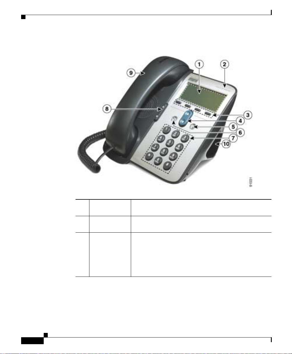
Figure 1-1 Cisco IP Phone Models 7905G and 7912G Features
1-2
1 LCD screen Displays features su ch as the tim e, date, you r phone
number, caller ID, call status, and softkey tabs.
2 Cisco IP Phon e
series type
Indicates the Cisco IP Phone ser ies to which th e phone
belongs.
3 Softkeys Enable you to e ngage any of the func ti ons di spla yed o n
the correspondin g LCD scr een tabs . Softkeys point to
feature options displayed along the bo ttom of the LCD
screen. Softkey functions change depending on the status
of your phone (for exampl e, if the phon e is ac tive or
idle).
Cisco IP Phone Models 7905G and 7912G Administrator Guide (SIP)
OL-4277-01
Page 27

Chapter 1 Overview of the Ci sco IP Phone Models 7905G and 7912G
Hardware Overview
4 Navigation
button
Enables you to scroll through text and select features
displayed on the LCD screen. Also provides access to
speed dial numbers when there are no text or features to
scroll through.
5 Menu button Provides access to phone services and setti ngs such as
messages, direct ori es, con tr ast, r ing soun d, net work
configuration, and status information.
6 Hold button Puts a current call on hold or ta kes a cal l off hold.
7 Dial pad Works exactly like the di al pad on a tra dition al
telephone.
8 Volume button Increases or decreases volume for the handset and
speaker. Also controls the rin ge r volum e (i f o n-h ook) .
OL-4277-01
9 Handset Functions like a traditional handse t. The light strip at the
top of the ha nds et b l inks wh en the p hone ri ngs a nd
remains lit to indicate a new voice mail message
(depending on y our m essag e syste m).
10 Footstand Allows the phone to stand at a convenient angle on a desk
or table.
Cisco IP Phone Models 7905G and 7912G Administrator Guide (SIP)
1-3
Page 28

Software Features
Software Features
The Cisco IP Phone models 7905 G and 791 2G su ppo rt t he f oll owing software
features:
• Protocols, page 1-4
• Basic Services, page 1-5
• Supplemental Services , pa ge 1-5
• SIP-Specific Services, page 1-6
Protocols
The Cisco IP Phone models 7905 G and 791 2G su ppo rt t he f ollowing pr ot ocols:
• Domain Name S yste m (DNS )
• Dynamic Host Configuration Protocol (DHCP)
• Internet Control Message Protocol (ICMP)
• Internet Protocol (IP)
Chapter 1 Overview of the CiscoIP Phone Models 7905G and 7912G
1-4
• Network Time Protocol (NTP)
• Real-Time Transport Protocol (RTP)
• Session Initiation Protocol (SIP)
• Transmission Control Protocol (TCP)
• Trivial File Transfer Protocol (TFTP)
• User Datagram Pr ot ocol (U DP )
Related Topics
• Basic Services, page 1-5
• Supplemental Services , pa ge 1-5
• SIP-Specific Services, page 1-6
Cisco IP Phone Models 7905G and 7912G Administrator Guide (SIP)
OL-4277-01
Page 29

Chapter 1 Overview of the Ci sco IP Phone Models 7905G and 7912G
Basic Services
The Cisco IP Phone models 7905G and 791 2G provide the fo llowing basic
services:
• Configuration using LCD screen menus, TF TP server, or web browser
• IP address assignment—DHCP or manual static IP address
• Configurable Type of Service (ToS) bit for Quality of Service (QoS)
• Configurable tone (busy tone, call waiting tone , dial tone , seco ndary dial
tone, reorder tone, ringb ack t one)
• Dial plan support
• Remote reset suppo rt
• G.711 u-law, G.711 A-law, and G.729A supp ort
• Voice-ac tivity-d et ecti on (VAD) and comfort-noise-ge ner ation ( CN G )
support for G.711 u-l aw and G.7 11 A-l aw, and support for G .729 A nnex B
• Dynamic jitter buffer for voice packets
Software Fea t ures
Related Topics
• Protocols, page 1-4
• Supplemental Services , pa ge 1-5
• SIP-Specific Services, page 1-6
Supplemental Services
The Cisco IP Phone models 7905 G and 791 2G su ppo rt t he f oll owing
supplemental services:
• Call waiting
• Calling line ID presentation/rejection (CLIP/CLIR)
• Three-way calling
• Conferencing bridge—up to three parties
• Call hold
OL-4277-01
Cisco IP Phone Models 7905G and 7912G Administrator Guide (SIP)
1-5
Page 30

Software Features
• Call transfer—attended and unattended
• Message-waiting indicator
Related Topics
• Protocols, page 1-4
• Basic Services, page 1-5
• SIP-Specific Services, page 1-6
SIP-Specific Services
The Cisco IP Phone models 7905G and 7912G support the following SIP-specific
services:
• Direct IP dial ing in a dd ition t o pr oxy -ro uted c a lls.
• Configurable periodic registration with a SIP proxy server.
• Authentication support for all SIP methods.
• Configurable NAT supp ort.
Chapter 1 Overview of the CiscoIP Phone Models 7905G and 7912G
1-6
• Configurable outbound proxy supp ort.
• Local support for call return (or call back), call forwarding, and call transfer.
• FQDN for SIP proxy and ou tboun d pro xy.
• Uses the same configurable MediaPort to transmit and receive RTP audio.
• Out-of-Band DTMF vi a RFC2 833 ( also known as AVT tones).
• UDP for SIP signaling.
• Message-waiting indication (MWI) provided via the telephone-handset LED
lamp.
• Distinctive ringing support via the SIP Aler t-In fo header.
Related Topics
• Protocols, page 1-4
• Basic Services, page 1-5
• Supplemental Services , pa ge 1-5
Cisco IP Phone Models 7905G and 7912G Administrator Guide (SIP)
OL-4277-01
Page 31

Chapter 1 Overview of the Ci sco IP Phone Models 7905G and 7912G
SIP Overview
Session Initiation Protocol (SIP) is the Internet Engineering Task Force (IETF)
standard for re al-time calls and conferenci ng ov er Internet Pr otocol (IP) . SIP is an
ASCII-based, applic ation-l ayer contr ol protoc ol that ca n be used to establis h,
maintain, and terminate calls between two or more endpoints.
Like other VoIP protoc ols, SIP provides sign aling and sessi on manage ment
within a packet telephon y network. Signal ing allows cal l information to be carr ied
across network bou ndari es. Sess io n ma na geme nt c on trols th e attri butes of an
end-to-end call .
This sect io n in c lu de s th es e to p ics:
• SIP Functions, page 1-7
• SIP Components, page 1-8
SIP Functions
SIP does the following:
• Determines the l oca tio n of th e t arget e ndpoi nt— SI P sup por ts a ddre ss
resolution, name mapping, and call redirection.
SIP Overview
OL-4277-01
• Determines the media capabilities of the target endpoint—Via Session
Description Protocol ( SDP), SIP deter mine s the lowest level of common
services between endpoi nts. Conf eren ces are est ablis hed using only the
media capabilities that can be supported by all endpoints.
• Determines the availability of the target endpoint—If a call cannot be
completed because the target endpoint is unavailable, SIP determines
whether the cal led part y is a lre ad y on th e phone o r d id n ot a nsw er in t he
allotted number of rings. It then returns a message indicating why the target
endpoint was unavailable.
• Establishes a session between the originating and target endpoint—If the call
can be completed, SIP estab lish es a session b etw een the end point s. SIP a lso
supports mid-call changes such as adding another endpoint to the conference
and changing media characteristic or codec.
• Transfers and terminates calls— SIP support s the transf er of calls from one
endpoint to another. During call transfer, SIP simply establishes a session
between the transferee and a new endpoint (specified by the transferring
Cisco IP Phone Models 7905G and 7912G Administrator Guide (SIP)
1-7
Page 32

SIP Overview
Related Topic
• SIP Components, page 1-8
SIP Components
SIP is a peer -to- peer pr otocol. The peers in a se ssion are call ed user agent s (U As) .
A user agent can function in either of two roles:
• User-agent client (UAC)—A client application that initiates the SIP request.
• User-agent server (UAS)—A server application that contacts the user when a
Typically, a SIP endpoint is capable of f unc tioni ng as e it her UAC or UAS (but
not both simultaneously ) during a tra nsaction. Whether it functions as UAC or
UAS depends on the UA that initiated the request.
Chapter 1 Overview of the CiscoIP Phone Models 7905G and 7912G
party) and terminates the session between the transferee and the transferring
party. At the end of a call, SIP terminates sessions between all parties.
Conferences can consist of two or more users an d can be est ablished using
multicast or multiple unicast sessions.
SIP request is received and returns a response on behalf of the user.
SIP servers can interact with other back-end application services such as
Lightweight Directory Acc ess Protocol (LDAP) servers, database
applications, and extens ible mark up langua ge (XML ) applica tions that
provide back-end services such as directory, authentication, and billing
services.
1-8
Figure 1-2 shows the architecture of a SIP network.
Cisco IP Phone Models 7905G and 7912G Administrator Guide (SIP)
OL-4277-01
Page 33

Chapter 1 Overview of the Ci sco IP Phone Models 7905G and 7912G
Figure 1-2 SIP Architecture
SIP proxy and
redirect servers
SIP
SIP SIP
user agents
SIP Overview
SIP gateway
SIP Client s
RTP
Legacy PBX
PSTN
72342
Related Topic
• SIP Functions, page 1-7
• SIP Clients, page 1-9
• SIP Servers, page 1-10
SIP clients include the following:
• Te lephones—Act as either UAS or UAC. The Cisco IP Phone models 7905G
and 7912G can initiate SIP requests and re spond to r equests.
• Gateways—Provide call control. Gateways provide many services, the most
common being translation betwee n SIP confere ncing endp oints of
transmission format, commu nicati ons procedu res, and co decs. Other
functions include ca ll setup an d clearin g on both the LA N side and the
switched-circuit network side.
OL-4277-01
Cisco IP Phone Models 7905G and 7912G Administrator Guide (SIP)
1-9
Page 34

SIP Overview
SIP Server s
Chapter 1 Overview of the CiscoIP Phone Models 7905G and 7912G
SIP servers include the following:
• Proxy servers—Rece ive SIP requests from a cli ent and forward them to the
next SIP server in the ne twork. Pr oxy se rvers c an pr ovide func ti ons suc h as
authentication, author i zati on, ne twor k ac cess co ntrol , r outi ng , re liabl e
request retransmission, and security.
• Redirect servers—Receive SIP requests, strip out the address in the re quest,
check its address tables for any other addresses that may be mapped to the one
in the request, and return the results of the address mapping to the client.
Basically, redirect servers provide the client with information about the next
one or more hops that a message should take and then the client contacts the
next hop server or UAS directl y.
• Registrar servers—Process requests from UACs for registration of their
current location. Registrar ser vers are ofte n coloc ated with re dire ct or proxy
servers.
1-10
Cisco IP Phone Models 7905G and 7912G Administrator Guide (SIP)
OL-4277-01
Page 35

CHAPTER
2
Installing the Cisco IP Phone Models 7905G and 7912G
This chapter provides information about installing the Cisco IP Phone models
7905G and 7912G at the en d user locat ion. It inc ludes the following secti ons:
• Prerequisites, page 2-1
• Safety, page 2-2
• Connecting to the Network, page 2-4
• Providing Power to the Cisco IP Phone, page 2-5
• Installing the Cisco IP Phone Models 790 5G and 7912G, page 2-6
• Verifyi ng Installati on, page 2-15
Prerequisites
The Cisco IP Phone models 7905G and 791 2G act as endp oints on an IP
telephony network, and have the fo llowing ne twor k r equi reme nts :
• An Ethernet conn ec tio n to a ne tw ork wit h SI P cli ent s a nd s ervers, as required
• A Trivial File Transfer Protocol (TFTP) server for storing IP phone profiles,
• A Dynamic Host Configuration Protocol (DH CP) server, if desired
OL-4277-01
if desired
Cisco IP Phone Models 7905G and 7912G Administrator Guide (SIP)
2-1
Page 36

Safety
Chapter2 Installing the Cisco IP Phone Models 7905G and 7912G
• A Call Control System
–
Proxy server—There must be a device running RFC 2543 SIP-compliant
software
–
Voice packet gateway—Required if you are connecting to the Public
Switched Telephone Network (PSTN)
Note If you use a firewall, Cisco re comme nd s tha t it be a Ci sco PIX firewall, Version
5 or later.
Related Topics
• Safety, page 2-2
• Connecting to the Network, page 2-4
• Providing Power to the Cisco IP Phone, page 2-5
• Installing the Cisco IP Phone Models 790 5G and 7912G, page 2-6
• Verifyi ng Installati on, page 2-15
Safety
2-2
To ensure general safety, follow these guidelines:
• Do not open or disassemble this product.
• Do not get this product wet or pour liquids into this device.
• Do not perform any action that creates a potential hazard to people or makes
the equipment unsa fe.
Warning
Cisco IP Phone Models 7905G and 7912G Administrator Guide (SIP)
Ultimate disposal of this product should be handled according to all national
laws and regulations. To see translations of the warnings that appear in this
publication, refer to the Regulatory Compliance and Safety Information
document that accompanied this device.
OL-4277-01
Page 37

Chapter 2 Installing the Cisco IP Phone Models 7905G and 791 2G
Safety
Warning
Warning
Warning
Warning
Read the installation instructions before you connect the system to its power
source. To see translations of the warnings that appear in this publication, refer
to the Regulatory Compliance and Safety Information document that
accompanied this device.
The plug-socket combination must be accessible at all times because it serves
as the main disconnecting device. To see transl ations of the warnings that
appear in this publication, refer to the Regulatory Compliance and Safety
Information document that accompanied this device.
Do not work on the syst em or connect or disconnect cables during periods of
lightning activity. To see transl ations of the warnings that appear in this
publication, refer to the Regulatory Compliance and Safety Information
document that accompanied this device.
This equipment is to be installed and maintained by service personnel only as
defined by AS/NZS 3260 Clause 1.2.14.3 Service Personnel. To see translations
of the warnings that appear in this publication, refer to the Regulatory
Compliance and Safety Information document that accompanied this device.
OL-4277-01
Warning
Warning
This product relies on the building’s installation for short-circuit (overcurrent)
protection. Ensure that a fuse or circuit breaker no larger than 120 VAC, 15A U.S.
(240 VAC, 10A international) is used on the phase conductors (all
current-carrying conductors). To see translations of the warnings that appear
in this publication, refer to the Regulatory Compliance and Safety Information
document that accompanied this device.
The device is designed to work with TN power systems. To see translations of
the warnings that appear in this publication, refer to the Regulatory Compliance
and Safety Information document that accompanied this device.
Cisco IP Phone Models 7905G and 7912G Administrator Guide (SIP)
2-3
Page 38

Chapter2 Installing the Cisco IP Phone Models 7905G and 7912G
Connecting to the Network
Related Topics
• Connecting to the Network, page 2-4
• Providing Power to the Cisco IP Phone, page 2-5
• Installing the Cisco IP Phone Models 790 5G and 7912G, page 2-6
• Verifyi ng Installati on, page 2-15
Connecting to the Network
The Cisco IP Phone 7912G has two RJ-45 ports labe lled “10/ 100 SW” and
“10/100 PC.” Each port supports 10/100 Mbps half- or full-duplex connections to
external devices. The Ci sco IP Phone 7905 G has one RJ -45 port la bel ed
“10 BASET.” This port supports 10 Mbps hal f- or full-du plex connect ions to
external devices. You can use Category 3 or 5 cab lin g for 10 -M bps c onn ect ions,
but you must use Category 5 c abling f or 100 M bp s conn ec tions. C isco
recommends that you use full-duplex mode on all ports (set at the switch) to avoid
collisions.
Use the 10BASET port on the Cisco IP Phone 7905G or the 10/ 100 SW po rt on
the Cisco IP Phone 7912G to co nnec t a phone to the n etwork. You must use a
straight-through c abl e on thes e p ort s. A ph one c a n al so ob tain inl ine power over
these connections.
Use the 10/100 PC port on the Cisco IP Phone 7912G to connect a network device,
such as a computer, to the phone. You must use a straight-through cable on this
port.
2-4
Figure 2-1 shows the connection ports on the back of the Cisco IP Phone 7905G .
Figure 2-2 shows the connection por t s on the b ack of the C isco I P Pho ne 791 2G .
Related Topics
• Safety, page 2-2
• Providing Power to the Cisco IP Phone, page 2-5
• Installing the Cisco IP Phone Models 790 5G and 7912G, page 2-6
• Verifyi ng Installati on, page 2-15
Cisco IP Phone Models 7905G and 7912G Administrator Guide (SIP)
OL-4277-01
Page 39

Chapter 2 Installing the Cisco IP Phone Models 7905G and 791 2G
Providing Power to the Cisco IP Phone
Providing Power to the Cisco IP Phone
The Cisco IP Phone can be powered by the following sources :
• External power—option al Cisco AC adapter and power co rd for con necting
to a standard wall receptacle.
• Inline power—provided to the Cisco IP Phone w hen con nected to a
Cisco C atalyst switch that is capable of providing inline power.
Note Only the network port supports in line power from the
Cisco C atalyst switches. The network port is labelled
“10 BASET” on the Cisco IP Phone 7905G and “10/1 00 SW” on
the Cisco IP Phone 7912 G.
• WS-PWR-PANEL—power patch panel tha t al lows the Cisc o I P Pho ne t o be
connected to existing Catalyst 400 0, 5000, and 60 00 family 10/1 00BaseTX
switchi ng modules.
This module sends power on pins 4, 5, 7, & 8, which are not used for Ethernet
signaling. The power patch panel attempts to verify that the attached device
is a Cisco IP Phone befor e providing power.
Related Topics
• Safety, page 2-2
• Connecting to the Network, page 2-4
• Installing the Cisco IP Phone Models 790 5G and 7912G, page 2-6
• Power Source Design, page 2-5
• Redundancy Feature, pag e 2-6
• Verifyi ng Installati on, page 2-15
Power Source Design
The phone and switch automatically determine which power source the phone
uses. If the power switches to a different sourc e, the phon e user will exper ience
different results ba sed on w hic h power sour ce i s bein g used by the phon e.
OL-4277-01
Cisco IP Phone Models 7905G and 7912G Administrator Guide (SIP)
2-5
Page 40

Installing the C isc oIP PhoneMode l s 7905G and 7912G
Use the following in for mat ion t o choo se a power sou rce for t h e phone :
• If you plug a phone into the optional pow er supply before plugging it into the
network, the phone is powered by the power supply.
• If you then unplug the phon e fr om the power sup ply, the phone resets. If the
switch port is configured for 10/ 100 Mbp s, t he swi tch re co gniz es the lo ss of
power and brings t he phon e ba ck u p.
• If the switch port is c onfigured f or 10 Mbps on ly, then you must u nplug th e
network connection an d p lug i t ba ck i nto t he p hone for t he s wit ch t o
recognize the p hone’s loss of power.
• If, however, you plugged the network co nne c tion i nto t he p hon e befor e yo u
plugged in the power cord, the phone receives power through the switch, and
unplugging the power co rd w ill n ot b ri ng down the p hon e. I f the sw itch
reboots, the phone will then be powered by the power cord.
Redundancy Feature
For redundancy, you can use the Cisco AC adapter even if you are using inline
power fr om the Cisco Cataly st s wi t ches . T he C is c o IP Phone can shar e the power
load being used from the inline power and external power source. If either the
inline power or the external power goes down, the phone can switch entirely to
the other power source.
Chapter2 Installing the Cisco IP Phone Models 7905G and 7912G
To use this re dund ancy fe a ture :
1. Set the inline power mode to auto on the Cisco Catalyst switch.
2. Connect the unpowered Cisco IP Phon e to the ne twork.
3. Connect the external power supply to the phone afte r the phone powers up.
Installing the Cisco IPPhoneModels 7905G and
7912G
You must install and configure the Cisco IP Phone before it will operate.
Installation consist s of ma king p ower and network conn ec ti ons. C onfigurat ion
consists of setting values for various parameters.
Cisco IP Phone Models 7905G and 7912G Administrator Guide (SIP)
2-6
OL-4277-01
Page 41

Chapter 2 Installing the Cisco IP Phone Models 7905G and 791 2G
Most frequently, the configuration p aram eter-value pairs fo r ea ch phone ar e
contained in a configuration file known as a profile that is stored on a TFTP server
on the network. When the phone powers up, it contac ts the TFTP server an d
downloads its profile. To do so, however, the phone must first receive a basic
configuration that instructs it to download its profile from the TFTP server and
informs it of the server location. Th is basic co nfiguration can be preprogrammed
on the phone before it is shipped to the end user, or it can be performed by the end
user when the phone is insta lled.
For more information about configuring a phone, see Chapter 3, “Configuring the
Cisco IP Phone Models 7905G and 7912G f or SIP.” For detailed information
about profiles, see Chapter 6, “C onfiguring the Cisco IP Phone Models 790 5G
and 7912G Using a TFTP Server.”
The following sections describe how to install the Cisco IP Phone models 7905G
and 7912G:
• Physical Installation of the Ci sco IP Phon e Models 79 05G an d 7912 G,
page 2-7
• Mounting the Phone to the Wall, page 2-12
• Basic Configuration of the Cisco IP Phone Models 790 5G and 7912G ,
page 2-13
Installing the CiscoIP Phone Models 7905G and 7912G
Related Topic
• Safety, page 2-2
Physical Installation of the Cisco IPPhone Models 7905G and
7912G
To install the Cisco I P Phone mode ls 79 05G and 7 912 G, p er fo rm t he f ollowing
steps.
See Figure 2-1 as you install the Cisco IP Phone 7905G, or see Figur e 2-2 as you
install the Cisco I P Ph one 7 912 G.
Cisco IP Phone Models 7905G and 7912G Administrator Guide (SIP)
OL-4277-01
2-7
Page 42

Installing the C isc oIP PhoneMode l s 7905G and 7912G
Chapter2 Installing the Cisco IP Phone Models 7905G and 7912G
Warning
To avoid electric shock, do not connect safety extra-low voltage (SEL V) circuits
to telephone-network voltage (TNV) circuits. LAN ports contain SELV circuits,
and WAN ports contain TNV circuits. Some LAN and WAN ports both use RJ-45
connectors. Use caution when connecting cables. To see translations of the
warnings that appear in this publication, refer to the Regulatory Compliance
and Safety Information document that accompanied this device.
Caution Do not cover or block the air vents on the back side of the Cisco IP Phone.
Overheating can cause permanent damage to the unit.
Caution If you plan to power your phone locally (instead of receiving power through the
Ethernet connectio n), use onl y a Cisco 48 volt power supply desig ned to work
with a Cisco IP Phon e.
Note Do not use hoo ded ca ble s w ith t h e Ci sco IP Pho ne mode ls 7 905G an d 7912 G
because they can cause the phone to rock .
Procedure
2-8
Step 1 Use a Category 3 or 5 straig ht-thr ough Ethe rnet ca ble to conne ct the 10 BASET
port on the Cisco IP Phone 7905G or the 10 /100 SW port on the Cisc o IP Phone
7912G to an Ethe rne t p ort.
Step 2 Connect th e ha ndset to the h andse t po rt.
Ensure that the end of the cord with the longer uncoiled section is connected to
the body of the phon e.
Step 3 Connect a Category 3 or 5 Ethernet cable to the 10/100 PC port on the back of the
Cisco IP Phone 7912G (optio nal).
Use a crossover Ethernet cable to connect from the access port to another Ethernet
device (such as a router or desktop computer) without using a hub. Otherwise, use
a straight-through Ethe rnet ca ble.
The Cisco IP Phone 7 905G does not have a 10/ 100 PC por t.
Cisco IP Phone Models 7905G and 7912G Administrator Guide (SIP)
OL-4277-01
Page 43

Chapter 2 Installing the Cisco IP Phone Models 7905G and 791 2G
Step 4 If the phone will not receive power through the Ethernet connection, connect the
power supply plug to the DC adapter port on the back of the phone. Then use the
power cable to connec t the p ower supply to a stand ard power out let.
After you connect a Cisco IP Phone to its power source, a startup process begins.
After several minutes, the LCD di spla ys a neut ral “r eady ” sc reen . Th e de tail s on
the screen might vary, but a ready screen typ ica lly di sp lays the dat e a nd time ,
extension number, and available softkeys. Startup is complete and the phone is
ready to use.
Softkeys point to featu re opt ions displ ayed a long the b otto m of the L CD s cr een.
Softkeys are flexible—they cha nge dep en ding on the sta tus o f the ph one. For
example, one set of so ftkey opt ion s a ppe ars wh en t he h an dse t i s p icked up , and
another set appear s when the phone is not in us e.
If the phone was prep rog ra mmed w ith i ts b asic c on figuration, i t b egins t o
automatically download its complete profile from the TFTP server. the initial
preloaded boot load firmware imag e is upgra ded to a firmware image that
supports a specific signall ing prot ocol .
Installing the CiscoIP Phone Models 7905G and 7912G
OL-4277-01
You or the end user must complete the steps in the “Basic Configuration of the
Cisco IP Phone Models 7905G and 7912G” section on page 2-13 before using the
phone.
Cisco IP Phone Models 7905G and 7912G Administrator Guide (SIP)
2-9
Page 44

Installing the C isc oIP PhoneMode l s 7905G and 7912G
Figure 2-1 Cisco IP Phone 7905G Cable Connections
3
Chapter2 Installing the Cisco IP Phone Models 7905G and 7912G
2
2-10
1
5
4
1 Network p ort (10BASE-T) Connec ts the pho ne to the Eth erne t port in
your workspace
2 Handset por t Connects the handset to the phone
3 DC ada pter p ort (48 VDC) Connects the power s upply plu g t o the phone
4 Power supply with DC
Connects to the AC power cable
output connector (if
included)
5 AC power cable with wall
socket plug (if inc lud ed)
Cisco IP Phone Models 7905G and 7912G Administrator Guide (SIP)
Connects the power s upply to a stan da rd
power outlet
91637
OL-4277-01
Page 45

Chapter 2 Installing the Cisco IP Phone Models 7905G and 791 2G
Figure 2-2 Cisco IP Phone 7912G Cable Connections
4
3
Installing the CiscoIP Phone Models 7905G and 7912G
OL-4277-01
1
2
1 Network port (10BASE-T,
100BASE-T)
2 Access port (10BASE-T,
100BASE-T)
6
5
91638
Connects the phone to th e Ether net port in
your workspace.
Connects the phone to th e Ether net port in a
desktop computer
3 Handset por t Connects the handset to the phone
4 DC ada pter p ort (48 VDC) Connects the power s upply plu g t o the phone
5 Power supply with DC
Connects to the AC power cable
output connector (if
included)
6 AC power cable with wall
socket plug (if inc lud ed)
Cisco IP Phone Models 7905G and 7912G Administrator Guide (SIP)
Connects the power s upply to a stan da rd
power outlet
2-11
Page 46

Installing the C isc oIP PhoneMode l s 7905G and 7912G
Related Topics
• Mounting the Phone to the Wall, page 2-12
• Basic Configuration of the Cisco IP Phone Models 790 5G and 7912G ,
page 2-13
Mounting the Phone to the Wall
You ca n moun t the Cisco I P Pho ne on the wal l by re moving the foot sta nd and
using the mountin g bra c ket on the b ac k of t he p hone , or y ou can use sp ec ial
brackets available in a Cisco IP Phone wall mount kit. (A wall mount kit must be
ordered separate ly f rom t he p hon e. ) If yo u a ttac h the Ci sco IP Phone to th e wal l
using the standard footstand a nd not the wall mou nt kit, you need to supply the
following tools and parts:
• Screwdriver
• Screws to secure the Cisco IP phone to the wall
To mount the phone on the wall using its mounting bracket, follow these steps:
Chapter2 Installing the Cisco IP Phone Models 7905G and 7912G
2-12
Procedure
Step 1 Remove the footstand from the phone.
Step 2 Modify the handset rest so that the handset remains on the ear-piec e rest when the
phone is vertically place d.
a. Remove the handset f rom the ear-piece re st.
b. Locate the ta b (ha nds et wall h ook) a t t he ba se of t he e ar-piec e r est.
c. Slide this tab out, rotate it 180 degrees (left to right) to expose a lip on which
the handset catches when the phone is vertical, and reinsert this tab.
d. Place the handset on the ear-piece rest.
For an illustrated procedure of modifying the handset rest, refer to Installing the
Wall Mount Kit for the Cisco IP Phone.
Cisco IP Phone Models 7905G and 7912G Administrator Guide (SIP)
OL-4277-01
Page 47

Chapter 2 Installing the Cisco IP Phone Models 7905G and 791 2G
Installing the CiscoIP Phone Models 7905G and 7912G
Step 3 Insert two screws into a w all stud or i nto w all anch ors, matc hing the scr e ws to t he
two screw holes on the bac k of t he p hone .
The keyholes fit standard phone jack mounts.
Step 4 Hang the pho ne on th e wal l.
Basic Configuration of the Cisco IP PhoneModels 7905G and
7912G
The basic configuration of a Cisco IP Phone provides the phone with the minimal
information that it needs to download its complete operational configuration
profile from a TFTP server. This information includes a value to enable TFTP
downloads, a value for the U RL for th e TFTP server that stores t he phone ’s
complete configuration file (also known as a profile), and a value for the
encryption key.
The following steps explai n how to perf or m this basic c onfigurati on f or the
Cisco IP Phone.As administrat or, you can preconfigure a phone bef ore it is
shipped to the en d u s er. Then, after the end user c on n ect s a p h one as d es cr ib ed in
the “Physical Installation of the Cisc o IP Phone Mode ls 79 05G and 7 912G”
section on page 2-7, the phone automatically down loads t he conf ig uration prof ile
and the latest phone softwa re from the TFT P server. The phone is ready for use
within seconds.
If preconfiguration is no t po ssibl e, t he en d u ser c an p er form t hes e st ep s aft er
connecting the pho ne .
OL-4277-01
Procedure
Step 1 Press the Menu button to access the Services menu.
Step 2 In the Services menu, use the Navigation button to selec t Settings, and then press
the Select softkey.
Step 3 In the Settings menu, use the Navigation button to select Network
Configuration, and then press the Select softkey.
Cisco IP Phone Models 7905G and 7912G Administrator Guide (SIP)
2-13
Page 48

Installing the C isc oIP PhoneMode l s 7905G and 7912G
Step 4 Unlock network configuration settings.
For instructions, see the “Unlocking and Locking Configurat ion Paramet ers”
section on page 5-4.
Step 5 In the Ne twork Co nfigurat ion menu , use the Navigation button to select
Alternate TFTP, and then press the Yes softkey.
Step 6 In the Ne twork Co nfigurat ion menu , use the Navigation button to select TFTP
Server, and then press the Edit softkey.
The current value fo r th e IP addre ss of t he TFTP server appea rs in the Cur ren t
Value and the New Value fields.
Step 7 Enter a new IP address in the New Value field.
Use the arrow softkey (<<) to delete existing characters. Use the * key on the
keypad to enter a period (.).
Note When the cursor moves over a character, the character is deleted and a
new character must be ent ere d. You cannot cancel individual cha rac ter
deletions, but you can use the Cancel softkey to back ou t of the s cree n
without saving your changes .
Chapter2 Installing the Cisco IP Phone Models 7905G and 7912G
2-14
Step 8 Press the Validate softkey.
Step 9 In the Ne twork Co nfigurat ion menu , use the Navigation button to select Profile
Encrypt Key, and then press the Edit softkey.
Step 10 Enter the encryption key using the keys on the keypad, and then pr ess the
Validate softkey.
For information about ent ering al pha- numer ic char acter s, se e the “Editing
Parameter Va lues” se ction on page 5-5 .
Step 11 Press the Save softkey.
Step 12 Press the Back softkey and then press the Exit softkey.
The phone downloads its conf igurati on profile and the latest ph one software from
the TFTP server.
Cisco IP Phone Models 7905G and 7912G Administrator Guide (SIP)
OL-4277-01
Page 49

Chapter 2 Installing the Cisco IP Phone Models 7905G and 791 2G
Verifying Installation
If you hear a di al ton e w hen y ou lif t the h andse t, you have install ed t he
Cisco IP Phone properly. If you experienc e any p rob lems , see Chapter 9,
“Troubleshooting the Cisco IP Phone Models 790 5G and 7912G .”
Verifying Installation
OL-4277-01
Cisco IP Phone Models 7905G and 7912G Administrator Guide (SIP)
2-15
Page 50

Verifying Installation
Chapter2 Installing the Cisco IP Phone Models 7905G and 7912G
2-16
Cisco IP Phone Models 7905G and 7912G Administrator Guide (SIP)
OL-4277-01
Page 51

CHAPTER
3
Configuring the
Cisco IP Phone Models 7905G and
7912G for SIP
This chapter provides an overview of configuring the Cisco IP Phone to operate
with the SIP firmware image.
This chapter includes the following sections:
• Overview of Configuration Methods, page 3-1
• Default Boot Load B eh avior, page 3-2
• Specifying a Preconfigured VLAN ID or Disabling VLAN IP Encapsulation,
page 3-4
• Basic Configuration Steps in a TFTP Server Environment, page 3-6
• Minimum Configuration Settings for the Cisco IP Phone Models 7905G and
7912G, page 3-9
Overview of Configuration Methods
You can co nfigure the Cisco IP Phone for SIP by using any of these me thods:
• TFTP server—Recommend ed met hod for depl oying a large num ber of
Cisco IP Phones. This method allows you to set up a unique configuration file
for each phone or to se t u p a co nfigurati on file th at i s co mmon t o al l
Cisco IP phones. These configuration files are called profiles. The
Cisco IP Phone Models 7905G and 7912G Administrator Guide (SIP)
OL-4277-01
3-1
Page 52

Default Boot Load B ehavior
Related Topics
Chapter 3 Configuring the CiscoIP Phone Models 7905G and 7912G for SIP
Cisco I P Phone can automatically download its latest profile from the TFTP
server when the phone powers up, is refreshed or reset, or when the specified
TFTP query interval expires.
For more information , see C hapter 6, “Co nfiguring the Cisc o IP Phone
Models 7905G and 7912G Us ing a TFTP Server.”
• Phone configuration menu s—Manu al method for configurin g an individual
phone. Each Cisco IP Phon e inclu des men us f or c onfiguring a variety o f
network and SIP settings.
For more information , see C hapter 5, “Co nfiguring the Cisc o IP Phone
Models 7905G an d 7912 G Usi ng t he Pho ne Men us.”
• Phone web page —Convenient if you plan to deploy a small number of
Cisco IP Phones in your ne twork. To use this method, the p hone must f irst ob tain
IP connectivity
For more information , see C hapter 7, “Co nfiguring th e
Cisco IP Phone Models 7905G and 7912G Us ing Web Pages.”
• Default Boot Load B eh avior, page 3-2
• Specifying a Preconfigured VLAN ID or Disabling VLAN IP Encapsulation,
page 3-4
• Basic Configuration Steps in a TFTP Server Environment, page 3-6
• Minimum Configuration Settings for the Cisco IP Phone Models 7905G and
7912G, page 3-9
Default Boot Load Behavior
Before you configure the Cisco IP Phone, you need to know how the default boot
load process works. Once you understand this process, you will be able to
configure the phone by fol lowing th e ins tr uct ions pr ovide d in thi s sec ti on and i n
the sections that follow.
It is important to underst and the boo t load pro cess because if your network
environment is not set up to follow this default behavior, you will need to make
the applicable configuration changes. For example, by default, the Cisco IP Phone
attempts t o con tac t a D HC P ser ver fo r t he n ec es sar y I P a dd re ss es to ac hi eve
Cisco IP Phone Models 7905G and 7912G Administrator Guide (SIP)
3-2
OL-4277-01
Page 53

Chapter 3 Configuring the Cisc o IP Phone Models 7905G and 7912G for SIP
network connectivity. Howev er, if your network does not use a DHCP server, you
must manually configure the IP address of the phone, the subnet mask used by the
phone, and the network gateway (default router) IP addr ess for the pho ne.
All Cisco I P Phones are shipped with a bootload image. However, because this
image is not a fully -fun ctional si gnali ng im age, th e imag e must be upgr aded. T he
image is designed to be auto matica lly upgrade d by a properly c onfigured TFTP
server. To configure the Cisco IP Phone to automatically upgrade to the latest
signaling image, see the “Upg rade code Parame ter Detai l” secti on on page 8-41 .
In addition, the Cisco IP Phone obtains its configuration file during the bootload
process.
Here is a summary of the default Cisco IP Pho ne behavior during its boo t-up
process:
1. The Cisco IP Phone uses the Cisco Discovery Protocol (CDP) to discover
which VLAN to enter. If the phone receives a VLAN ID response from the
network switch, the phone enters that VLAN and adds 802.1Q VLAN tags to
its IP packet s. If the phone does not receive a response with a VLAN ID from
the network switch, the phone assumes it is not operating in a VLAN
environment and does not perform VLAN tagging on its packets.
Default Boot Load Behavior
OL-4277-01
Note If your network environment is not set up to handle this default behavior,
make the necessary configuratio n changes by referring to the “Specifying
a Preconfigured VLAN ID or Disabling VLAN IP Encapsulation” section
on page 3-4.
2. The phone contacts the DHCP ser ver to request its own IP address.
Note If your network do es not use a DHCP server, you must m an ual ly
configure the IP address of the phone, the subnet mask used by the phone,
and the network gateway (de fault r out er) I P a ddress for the phone . For
more information, see the “Minimum Configuration Settings for the
Cisco IP Phone Models 7905G and 79 12G” sect ion on p ag e 3-9.
3. The phone also requests the IP add ress of the TFTP se rver from the DHCP
server.
Cisco IP Phone Models 7905G and 7912G Administrator Guide (SIP)
3-3
Page 54

Chapter 3 Configuring the CiscoIP Phone Models 7905G and 7912G for SIP
Specifying a Preconfigured VLAN ID or Disabling VLA N I P Encapsulation
4. The phone downloads a pro file from the T FT P se rver. To do so, it requests
the following profiles from the TFTP server, in the order shown, until a file
exists. Then it downloads that file. In the file names, xxxxxxxxxxxx is the
hexadecimal representation of the phone’s MAC address. (The first three files
are not used for SIP. They are included for compatibility reasons.)
–
SEPxxxxxxxxxxxx.cfg.xml
–
XMLDefault.cnf.xml
–
SEPDefault.cnf
–
ldxxxxxxxxxxxx (for the Cisco IP Phone 7905G ) or gkxxxxxxxxxxxx (for
the Cisco IP Phone 7912 G)
–
lddefault.cfg (fo r th e Cisco I P Pho ne 79 05G ) or g kde fault. cf g (for t he
Cisco IP Phone 7912G)
Related Topics
• Specifying a Preconfigured VLAN ID or Disabling VLAN IP Encapsulation,
page 3-4
• Basic Configuration Steps in a TFTP Server Environment, page 3-6
• Minimum Configuration Settings for the Cisco IP Phone Models 7905G and
7912G, page 3-9
Specifying a Preconfigured VLAN ID or Disabling
VLAN IP Encapsulation
If you want the Cisco IP Phone to use a preconfigured VLAN ID instead of using
the Cisco Discovery Protocol to locate a VLAN, or if you want to disable VLAN
IP encapsulation, you may need to configure the following parameters. (For more
information about t hese para meter s, see th e “Network Parameters” section on
page 8-2.) See Table 3-1 for information about which VLAN-related parameters
and bits to co nfigure de pendi ng on y our ne twork e nvironmen t.
• OpFlags parameter:
–
Bit 4—Enable the use of user-specified voice VLAN ID
–
Bit 5—Disable VLAN IP encapsulation
–
Bit 6—Disable CDP discovery
Cisco IP Phone Models 7905G and 7912G Administrator Guide (SIP)
3-4
OL-4277-01
Page 55

Chapter 3 Configuring the Cisc o IP Phone Models 7905G and 7912G for SIP
Specifying a Preconfigured VLAN ID or Disabling VLAN IP Encapsulation
• VLANSetting parameter:
–
Bits 0-2—Specify VLAN CoS bit value (802.1Q priority) for signaling
packets
–
Bits 3-5—Specify VLAN CoS bit value (802.1Q priority) for aud io packets
–
Bits 18-29—Us er-speci fied 80 2.1 Q VLA N I D
Table 3-1 VLAN-Related Features and Corresponding Configuration
Parameters
Feature OpFlags Bit 4 OpFlags Bit 5 OpFlags Bit 6
Static VLAN101VLAN ID
CDP-acquired
VLAN
No VLAN — 1 — Not applicable
No CDP — — 1 Not applicable
No CDP and no
VLAN
1. This variab le is no t ap pl icab le to t h e fea tur e a nd t he s ett in g of t his variable does not af fe ct the feat u re.
000Not applicable
011Not applicable
VLANSetting
Bits 18-29
1
1
1
1
OL-4277-01
Example
The following procedure shows you how to configure the OpFlag s and
VLANSetting parameters to allow the phone to use a user-specified VLAN ID. In
this example, the voice VLAN ID is 115 (in decimal format).
Step 1 Set bits 4-6 of the OpFlags parameter to 1, 0, and 1, respectively. This setting
translates to the following bitmap:
xxxx xxxx xxxx x xx x xxx x xx xx x1 01 x xxx
The remaining bits of the OpFlags parameter, using all default values, make up
the following bitmap representation:
0000 0000 0000 0 00 0 000 0 00 00 0x xx 0 010
Cisco IP Phone Models 7905G and 7912G Administrator Guide (SIP)
3-5
Page 56

Chapter 3 Configuring the CiscoIP Phone Models 7905G and 7912G for SIP
Basic Configuration Steps in a TFTP Ser ve r Environment
Therefore, the resulting value of the OpFlags parameter becomes the following
bitmap representation:
0000 0000 0000 0 00 0 000 0 00 00 01 01 0 010
In hexadecimal for ma t, this value i s 0x00 000 052.
Step 2 Set bits 18-29 of the VLANSetting parameter to v oice VLAN ID 115 . This setting
translates to the following bitmap
xx00 0001 1100 1 1x x xxx x xx xx xx xx x xxx
where 00000111001 1 is the bina ry rep res ent ation of the d eci mal value 115.
The remaining bits of the VLANSett ing paramete r, using all default values, make
up the following representation:
00xx xxxx xxxx x x0 0 000 0 00 00 00 10 1 011
Therefore, the resulting value of the VLANSetting parameter becomes the
following bitmap representation:
0000 0001 1100 1 10 0 000 0 00 00 00 10 1 011
In hexadecimal forma t, th is value is 0x01 cc 00 2b.
Related Topics
• Default Boot Load B eh avior, page 3-2
• Basic Configuration Steps in a TFTP Server Environment, page 3-6
• Minimum Configuration Settings for the Cisco IP Phone Models 7905G and
7912G, page 3-9
Basic Configuration Steps in a TFTP Server
Environment
The following table shows the basic steps for upgrading the firmware image for a
Cisco IP Phone, configuring the phone, and making it operational in a typical SIP
environment, which includes a TFTP server.
Cisco IP Phone Models 7905G and 7912G Administrator Guide (SIP)
3-6
OL-4277-01
Page 57

Chapter 3 Configuring the Cisc o IP Phone Models 7905G and 7912G for SIP
Basic Conf i guration Steps in a TFTP Server Environment
Procedure Reference
Step 1
Step 2
Download the desired phone release software
zip file from the Cisco website and store it on
the TFTP server.
Follow these basic steps to create a unique
profile, which actually entails creating two
files:
1. Create a phone profile that contains
parameters that are common to all
Cisco IP Phones in your network.
2. Create a unique profile text file that
contains parameters th at are s pecif ic to a
Cisco IP Phone.
Make sure to use an Include parameter
in the unique profile to pull in values
from the common co nfiguration file.
See the “Setting Up the TFTP
Server with Cisco IP Phon e
Software” section on page 6-4.
See Chapter 6, “Configuring the
Cisco IP Phone Model s 7905 G
and 7912G Using a TFTP
Server.”
OL-4277-01
Step 3
Step 4
3. Convert the unique configuration file to
binary format.
4. Place the uniq ue binary configuratio n
file on the TFTP server.
Optionally, create a default profile called
lddefault.cfg for the Ci sco IP Phone 7905G
or gkdefault.cf g for the C isco IP Phone
7912G, which the phone will download from
the TFTP server only if the un ique p rofile
called ldxxxxxxxxxxxx or gkxxxxxxxxxxxx
does not exist on the TFTP server.
Configure the upgradecode parameter so that
the phone will obtain th e corre ct signal ing
image from the TFTP server when the phone
powers up.
Cisco IP Phone Models 7905G and 7912G Administrator Guide (SIP)
See the “Creating a Default
Profile” section on page 6-13 .
See the “Upgradecode Parameter
Detail” section on page 8-41.
3-7
Page 58

Chapter 3 Configuring the CiscoIP Phone Models 7905G and 7912G for SIP
Basic Configuration Steps in a TFTP Ser ve r Environment
Procedure Reference
Step 5
Configure the desired interval for the pho ne
to contact the TF TP ser ver to ch eck for a
configuration-file update or an upgrade of
the signaling image file.
Use the CfgInterval parameter to set this
interval.
Step 6
Configure the metho d by whi ch t he ph one
will locate the TFTP server at boot up time.
Step 7
Step 8
Power up the phone. —
If you make configuration change s to the
phone or if you upg rade th e sign ali ng imag e
on the TFTP server, you can re fresh t he
phone so that th ese chang es take effect
immediately. Otherwise, these changes will
take effect when the specified interval
(CfgInterval par amet er value) f or the T FTP
query expires.
See the “Network Parameters”
section on page 8-2.
See the“Configuring the
Cisco IP Phone to Obtain its
Configuration File from the
TFTP Server” section on
page 6-5.
See the “Refreshing or Resetting
the Cisco IP Phone” s ecti on on
page 6-17.
3-8
Table 4-1 on page 4-2 conta ins a list of all re quired SIP parameters . These
parameters must be properly c onfigured for the Cisco IP Phone to work.
For descriptions of important Cisco IP Phone SIP services that you can configure,
and references to their configuration parameters, see the “Important Basic SIP
Services” section on page 4-2 an d the “Additional SIP Services” section on
page 4-4.
Table 4-3 on page 4-12 l ist s, i n alph ab eti c al ord er, various fe atur es t ha t yo u ca n
configure for the Cisco IP Phone.
Cisco IP Phone Models 7905G and 7912G Administrator Guide (SIP)
OL-4277-01
Page 59

Chapter 3 Configuring the Cisc o IP Phone Models 7905G and 7912G for SIP
Minimum Configuration Settings for the Cisco IPPhoneModels 7905G and 7912G
Related Topics
• Default Boot Load B eh avior, page 3-2
• Specifying a Preconfigured VLAN ID or Disabling VLAN IP Encapsulation,
page 3-4
• Minimum Configuration Settings for the Cisco IP Phone Models 7905G and
7912G, page 3-9
Minimum Configuration Settings for the
Cisco IP Phone Models 7905G and 7912G
The Cisco IP Phone r equire s the following mi nim um settin gs f or ne twor k
connectivity:
• IP address
• Subnet mask
• Network gateway (default router) IP ad dress
These settings can be configured usi ng any of the metho ds describ ed in the
following sections:
• Making Settings with a D HCP Server, page 3-9
• Making Settings Manuall y, page 3 -10
Related Topics
• Default Boot Load B eh avior, page 3-2
• Specifying a Preconfigured VLAN ID or Disabling VLAN IP Encapsulation,
page 3-4
• Basic Configuration Steps in a TFTP Server Environment, page 3-6
Making Settings with a DHCP Server
If your Cisco IP Phone n etwork co ntai ns a D HCP s er ver, the Cisco I P Pho ne
automatically learns its IP address, subnet mask, and network gateway from the
DHCP server when the phone starts up.
Cisco IP Phone Models 7905G and 7912G Administrator Guide (SIP)
OL-4277-01
3-9
Page 60

Chapter 3 Configuring the CiscoIP Phone Models 7905G and 7912G for SIP
Minimum Configuration Setti ngs for the Cisco IP Phone Models 7905G and 7912G
Making Settings Manually
If your network do es not use a DHCP server, you must m an ual ly sp eci fy the IP
address of the phone, the subnet mask used by the phone, and the network gateway
(default router) IP ad dre ss f or the phon e. You can specify this inf ormat ion usi ng
the phone’s Network Configuration menu, using a profile, or using a phone’s web
page.
When you manually spec ify the se values, y ou mu st disabl e D HCP by u sin g th e
DHCP Enabled parameter on t he Network Con figuration menu or the Dhcp
parameter in a profile or web page.
To manually specify t he I P a ddres s, subn et ma sk, a nd default rout er IP ad dress,
use these parameters:
Parameter on Network
Setting
IP address of a phone IP Address StaticIP
Subnet mask us ed by
the phone
Network gateway
(default router) IP
address used by the
phone
For detailed information about configuring menus on the phone, see Chapter 5,
“Configuring the Cisco IP Phone Models 79 05G and 7912G Using the Phon e
Menus.”
For detailed informa tion a bo ut c on figuring th rough p rofiles, see Ch apter 6,
“Configuring the Cisco IP Phone Models 79 05G and 7912G Using a TFTP
Server.”
For detailed inform atio n abo ut con figuring thr ough a phon e’s web page, see
Chapter 7, “Configuring the Cisco IP Phone Models 7905G and 7912 G Using
We b Pages.”
Configuration Menu
Subnet Mask StaticNetMask
Default Router StaticRoute
Parameter in Profile or on
Web P age
3-10
Cisco IP Phone Models 7905G and 7912G Administrator Guide (SIP)
OL-4277-01
Page 61

CHAPTER
4
Basic and Additional SIP Services
This chapter provides info rmat ion about co nfiguring SI P service s that ar e
supported on the Cisc o IP Phone model s 790 5G and 79 12G. For de taile d
information about any par ameter me ntioned i n the foll owing section s, see
Chapter 8, “Profile and Web Page Parameters and Defaults.”
This chapter includes these topics:
• Important Basic SIP Services, page 4-2—Describes paramet ers that y ou must
configure for the Cisco IP Phone to function in a SIP environment.
• Additional SIP Services, pa ge 4-4—Contains information about additional,
commonly used SIP feat ures , with re ferenc es to the pa ramet ers for
configuring these services.
• Complete Reference of all Cisco I P Phone SIP Services, page 4-12—
Contains a complete listi ng of Cisc o IP Phone s erv ices that ar e suppor ted fo r
SIP, and includes cross references to the parameters for configuring these
services. Includes services not described in the sections about the basic SIP
services and the commonly used a dditional SIP servic es.
OL-4277-01
Cisco IP Phone Models 7905G and 7912G Administrator Guide (SIP)
4-1
Page 62

Important Basic SIP Services
Important Basic SIP Services
This section provides descriptions and cross references for configuring required
SIP parameters and for configuring oth er importa nt basic SIP ser vices. This
section includes these topics:
• Required Parameters, page 4-2
• Establishing Authentication, page 4-4
• Configuring Refresh I nte rval, pa ge 4-4
Required Parameters
Table 4-1 shows the SIP param eters tha t you must su pply fo r a Cisc o IP Pho ne.
The Parameter fields in this table show each parameter name as it appears on a
phone’s web page or in its profile (“web page or profile”), or on the phone’s
Network Configuration menu or SIP Configuration menu (“ on phone menu” ).
For more detailed explanations of these parameters, see Chapter 5, “Configuring
the Cisco IP Phone Models 7905G and 79 12G Using th e Phone Menu s,” and
Chapter 8, “Profile and Web Page Parameters and Defaults.” These chapters also
contain information about other configuration parameters.
Chapter 4 Basic and Additional SIP Services
Table 4-1 Required SIP Parameters and Defaults
Parameter Description
SIPRegInterval
(web page or pro file)
Register Expires
(on phone menu)
MAXRedirect
(web page or pro file)
SIPRegOn
(web page or pro file)
Register with Proxy
(on phone menu)
Cisco IP Phone Models 7905G and 7912G Administrator Guide (SIP)
4-2
Number of seconds between registration
renewal.
Maximum number of times to try
redirection.
Enable SIP registration. 0 1 0
Minimum
Value
1 86400 3600
0105
Maximum
Value
Default
Value
OL-4277-01
Page 63

Chapter 4 Basic and Additional SI P Services
Table 4-1 Required SIP Parameters and Defaults (continued)
Important Basic SIP Services
Parameter Description
NA TIP
(web page or pro file)
NAT WAN IP Address
WAN address of the attached router/NAT;
currently only used to support SIP behind a
NAT.
(on phone menu)
SIPPort
Port to listen for incoming SIP requests. 1 65535 5060
(web page or pro file)
Local SIP Port
(on phone menu)
MediaPort
Base port to receive RTP media. 1 65535 16384
(web page or pro file)
Local RTP Port
(on phone menu)
OutBoundProxy
(web page or pro file)
Outbound Proxy
(on phone menu)
Outbound proxy server IP address or full y
qualified domain name (FQDN) for all
outbound SIP requests.
All SIP requests are sent to OutBoundProxy,
when configured, instead of to the
configured Proxy.
Proxy
(web page or pro file)
SIP proxy server IP address or fully
qualified domain name (FQDN).
Minimum
Value
Maximum
Value
Default
Value
— — 0.0.0.0
——0
——0
SIP Proxy
(on phone menu)
OL-4277-01
Cisco IP Phone Models 7905G and 7912G Administrator Guide (SIP)
4-3
Page 64

Additional SIP Services
Establishing Authentication
The UseLoginID parameter lets you select the user ID for authentication of the
phone to the remote end as fo llows:
• If UseLoginID is set to 0, the user ID (set with the UID parameter) is used
with a user-supplie d p assword (se t w ith th e PWD p ara mete r) f or
authentication.
• If UseLoginID is se t to 1, yo u m ust s uppl y a log i n ID (set wi th the Lo ginI D
parameter) and a password (set with the PWD parameter) for authentication.
Configuring Refresh Interval
When the value specified with the CfgInterval parameter is reached, the
Cisco I P Phone attempts to refresh its configuration file from the TFTP server.
(You can manually perform a refresh before the scheduled refresh as explained in
the “Refreshing the Cisco IP Phone” sect ion on page 6-17 .)
When a Cisco IP Phone contacts the TFTP server, it also checks to see if a
firmware image has been placed on the TFTP server. If such an image exists, the
phone will download thi s ima ge.
Chapter 4 Basic and Additional SIP Services
Additional SIP Services
Table 4-2 describes additional SIP services and provides references to additional
information. These services are listed alphabetically.
Note Many of the descriptions in Table 4-2 refer to spec ific pa rameters that you can set
in a profile or from a p hon e’s web page. For the c orre spon ding pa rame ter in t he
phone configuration menus, see A ppend i x B, “Pho ne Me nu, Web Page, and
Profile Equivalent Parameters.”
Cisco IP Phone Models 7905G and 7912G Administrator Guide (SIP)
4-4
OL-4277-01
Page 65

Chapter 4 Basic and Additional SI P Services
Additional SIP Services
Table 4-2 Additional SIP Services
SIP Service Description Reference
Advanced audio
configuration.
The TOS parameter (which specifies the default IP
precedence of U DP pac kets) and A u dioM ode
parameter (which spec ifies the audio ope rating mo de)
allow you to tune au dio c on figurati on.
Call preferences The GUI Show Mask or CallPrefGuiShow specify
which parameter s, if any, appear on the Call
Preference s m en u on t he pho ne . Th e G UI Se t M as k o r
CallPrefGuiSet parameters specify which parameters
on the Call Preferences menu on the phon e can be
changed by an end user. You can use these para meters
to offer specific features on a subscription basi s
Comfort noise When silence supp ressi on i s tur ne d o n in G.7 11, th e
Cisco IP Phone calculates and transmits its noise level
to the far end t o enab le the rem ote endp oint to gene rate
the appropriate amount of comfort noise. This feature
provides the remote user with a similar experience to
that of a PSTN c al l an d prevents sile nt ga ps wh en
neither party is talking.
See the “SIP Parameters”
section on page 8-9 and
the “Audio Parameters”
section on page 8-24.
See the “Call Pref er en ce
Parameters” section on
page 8-13.
See the “Audio
Parameters” section on
page 8-24.
You ena ble or disable silence suppression with bit 0 in
the AudioMode p aram eter.
Debugging
diagnostics
You can use the following param eters to tr oublesho ot
operation i ss u es:
• NP rintf—Spe cifies the IP address and por t where
debug information is sent.
• TraceFlags—Turns on specific trace features.
Dial plan You can use the DialPlan parameter to set specific dial
plan rules and ti meout v alue s. Man y of th ese v alues a re
determined on a c ount ry-by-co untry b asis.
Disabling access
to the web
interface
To prevent tampering and unauthor ized ac cess to the
Cisco IP Phone configuration, you can use the OpFlags
parameter to prevent configuring the phone through the
web.
Cisco IP Phone Models 7905G and 7912G Administrator Guide (SIP)
OL-4277-01
See the “Network
Parameters” section on
page 8-2.
See the “SIP Parameters”
section on page 8-9.
See the “Network
Parameters” section on
page 8-2.
4-5
Page 66

Chapter 4 Basic and Additional SIP Services
Additional SIP Services
Table 4-2 Additional SIP Services (continued)
SIP Service Description Reference
Distinctive
ringing support
DNS SRV
support
Hardware
information
If an incoming INVITE contains an Alert-Info header
with the name Bellcore-dr1, Bellcore-dr2,
Bellcore-dr3, Bellcore-dr4, or Bellcore-dr5, the phone
will play the ring pattern r
, where n = 1, 2, 3, 4, or 5 as
n
specified in Bellcore GR506. If the Alert-In fo header is
not present or if the ring pattern na me is unknown, the
phone will play the default ring pattern Bellcore-dr1.
The Cisco IP Phone supports DNS SRV lookup for the
SIP proxy server. If the Proxy param ete r value is a
domain name, the ph one perf orm s a D NS SRV lookup
for the SIP proxy server. A DNS SRV lookup results in
one of the fol lowing co ndi tions:
• Z ero host is retur ned or DNS SRV lookup failed.
The phone then performs a regul ar DNS A-re cord
lookup for the given name.
• One host is returned. The single host is use d as the
primary proxy far m.
• Two or more hosts are returned. The two hosts with
the highest priorities are used as the primary and
backup proxy farms.
You can view Cisco IP Phone hardware information on
the phone’s Model Information menu and on the Device
Information area in a phon e’s web page.
—
See the “SIP Parameters”
section on page 8-9.
See the “Model
Information Me nu”
section on page 5-17 and
the “Device Infor matio n”
section on page 7-4.
4-6
Cisco IP Phone Models 7905G and 7912G Administrator Guide (SIP)
OL-4277-01
Page 67

Chapter 4 Basic and Additional SI P Services
Additional SIP Services
Table 4-2 Additional SIP Services (continued)
SIP Service Description Reference
NAT gateway Network Address Translation (NAT) supports port
mapping and forwarding to stand ard default SIP
signaling port 5060 and media base port 16384, or other
ports as conf igured for the Cisc o IP Phone . Media po rts
are evenly numbered from the base port . NAT must
support multiple port mappings. The phon e can use up
to four media ports to handl e conferenc e calls on bot h
lines. For example, if media base port 16384 is used for
one call, the next call uses port 16386 an d other ca lls
will use ports 16388 and 16390. (Route rs such as
D-Link, WinRoute, and WinProxy m ay n ot rout e
correctly if both caller and callee are behind the same
NA T.)
T o conf igure the phone to work in a NAT environment,
make the following settings:
• Use the StaticRoute parameter to specify the LAN
IP address of the NAT through whic h th e phone
will communicate.
See the “Network
Parameters” section on
page 8-2 and the “SIP
Parameters” section on
page 8-9.
OL-4277-01
• Use the NATIP parameter to specify the WAN IP
address of the NAT through which all external SIP
user agents will communicate.
• Optionally use the SIPPort parameter to specify a
new port for SIP messages.
• Optionally use the MediaPort parameter to specif y
a new base port for RTP media.
Cisco IP Phone Models 7905G and 7912G Administrator Guide (SIP)
4-7
Page 68

Chapter 4 Basic and Additional SIP Services
Additional SIP Services
Table 4-2 Additional SIP Services (continued)
SIP Service Description Reference
NA T/PAT
translation
To maintain Network Address Translation/Port
Address Translation (NAT/PAT) for a session, the
Cisco IP Phone can be configured to periodically send
a dummy UDP packet to a server (the ph one doe s not
expect any response from the server) .
To specify this configuration, use these parameters:
• NatTimer—Bits 0 to 11 are for specifying the
retransmission period.
• NatServer—Specifies the server to which the
dummy packet is sent.
Network timing You can fine tune your network tim ing by making the
following settings:
• Use the TimeZone parameter to specify the
time-stamp for incoming calls (offset from
Greenwich Mean Time).
See the “SIP Parameters”
section on page 8-9.
See the “Network
Parameters” section on
page 8-2 and the “Audio
Parameters” section on
page 8-24.
4-8
• Use the NTPIP parameter to specify the IP address
of the Network Time Protocol (N TP) server. NTP
is a protocol built on top of TCP that ensures
accurate local time-k eeping with ref erence to radio
and atomic clocks located on the Internet.
• Use the AltNTPIP parameter to specify an
alternate NTP server IP address.
• Use the ConnectMode parameter to specify the
connection mode of the SI P prot ocol .
Cisco IP Phone Models 7905G and 7912G Administrator Guide (SIP)
OL-4277-01
Page 69

Chapter 4 Basic and Additional SI P Services
Additional SIP Services
Table 4-2 Additional SIP Services (continued)
SIP Service Description Reference
Proxy
Redundancy
support
The Cisco IP phone supports next hop server
redundancy when a f ull y q ual ified doma in na me
(FQDN) is specified for the Proxy or Outboun d Proxy
parameter. When sending a SIP request, the phone
performs a DNS SRV records query for the domain
name. The phone selects two recor ds from the result
and identifies them as Primary Proxy Farm (PPF) and
Alternate Proxy Farm (APF). Ea ch farm may co ntain
up to five IP addresses. If a DN S SRV record does not
exist, the phone performs a DNS A records query fo r
the domain name, which is no w considered the Pri mary
Proxy Farm with no Alterna te Pr oxy Farm. The p hone
accepts up to five IP addresse s from th e query r esu lt.
The phone retries with the alternate next hop server for
the following SIP requests: RE GIST ER, I NVI TE,
CANCEL, BYE, REFER, and NOTIFY. If sending one
of these requests results in a 5xx response, no response,
or ARP timeout, the phone attempts the same request
with an alternate destination IP address derived from
the next hop domain name. If both primary a nd
alternate farms exist, the phone attempts the primary
farm first and then the alternate farm. The phone will
attempt all the IP addresses in one farm before
switching to t he o t her fa rm . Once th e pho ne finds a
responding next hop server, it remembers the farm and
IP address of the server and keeps using it for the given
domain name until it fails or expires. If the request still
fails after all the possible IP addresses are attempted,
the phone considers the request as failed.
See the “SIP Parameters”
section on page 8-9.
OL-4277-01
If a server in the alternate proxy farm is active at the
moment, the p hon e ca n be c on figured to ret ry t he
primary proxy farm after the number of seconds
specified by the AltProxyTimeout parameter. If this
value is 0, the phone rema ins w ith t he a ltern at e p rox y
farm until all the IP addresses in the farm are down
before attempti ng the pri mary pr oxy farm aga in.
Cisco IP Phone Models 7905G and 7912G Administrator Guide (SIP)
4-9
Page 70

Chapter 4 Basic and Additional SIP Services
Additional SIP Services
Table 4-2 Additional SIP Services (continued)
SIP Service Description Reference
Progress tones Valu es for the following parame ters must be
determined based on th e countr y in which th e
Cisco IP Phone is located:
• DialTone
• DialTone2
• Bu syTone
• Reor derTone
• Rin gBackTone
• CallWaitTone
Receiver-tagged
VIA header
You ca n use t he C onn ec tMo de pa ram ete r to disa ble or
enable the processing of the received = parameter in the
Via header. This feature is disable d by default.
Setting up and
placing a call
You can user the Cisco IP Phone to make a direc t
IP-to-IP calls without usi ng a SIP proxy.
without using a
SIP proxy
See the “Tone
Parameters” section on
page 8-21.
See the “Audio
Parameters” section on
page 8-24.
See the “Setting Up and
Placing a Call Without
Using a SIP Proxy”
section on page 4-10.
Setting Up and Placing a Call Without Using a SIP Proxy
The Cisco IP Phone models 7 905 G a nd 791 2G su pport d irect IP -to- IP calls
without using a SIP proxy. When a call is placed, the phone sends the INVITE
request directly t o th e re mote us er a ge nt an d expe cts the u sua l 10 0/180 /2 00
responses from the user agent.
Cisco IP Phone Models 7905G and 7912G Administrator Guide (SIP)
4-10
OL-4277-01
Page 71

Chapter 4 Basic and Additional SI P Services
To configure a Cisco IP Phone for calls that do not use a SIP proxy, set the
following parameters to the values shown:
Additional SIP Services
Parameter on SIP
Configuration Men u
Parameter in Profile
or on Web Page Setting
SIP Proxy Proxy 0 (zero) or No
User ID UID Telephone number of t he
Register with Proxy SipRegOn 0 (zero) or No (disables SIP
To place an IP call, dial the tel ephone nu mber a nd the IP addre ss of the rem ote
user agent using this format:
phone_number** IP ad dr ess
Use the star (*) key on the te leph one keypa d to re pr es ent the do t (. ) in a n IP
address. If you are using on-hook dialing, press the Dial softkey to terminate the
dial string and place the call . If you are using off-hook dia ling, press t he pound
(#) key on the telep hon e keypad t o te rmin ate th e di al stri ng a nd pla ce t he ca ll
Note URL dialing is not supported.
For example, to place a call to a user ag ent w ith an ID of 408- 555-1 212 at IP
address 192.168.1.1 00, ente r the following strin g on your te lephon e keypad:
4085551212**192*168 *1*100
phone
registration with a SIP proxy
server)
OL-4277-01
Related Topics
• Chapter 5, “Configuring the Cisco IP Phone Models 7905G and 7912G Using
the Phone Menus,”
• Chapter 6, “Configuring the Cisco IP Phone Models 7905G and 7912G Using
a TFTP Server,”
• Chapter 7, “Configuring the Cisco IP Phone Models 7905G and 7912 G
Using Web Pages.”
• Chapter 8, “Profile and Web Page Parameters and Defaults.”
Cisco IP Phone Models 7905G and 7912G Administrator Guide (SIP)
4-11
Page 72

Chapter 4 Basic and Additional SIP Services
Complete Reference of all Cisco IP Phone SIP Services
Complete Reference of all CiscoIP Phone SIP
Services
Table 4-3 lists all configurab le feat ures for t he Cisco IP Phone usi ng SIP. It also
lists the names of the parameters used to configure the features.
Table 4-3 Configurable Features and Related Parameters
Related Parameter in Profile
Configurable Feature
802.1Q packet tagging VLANSetting Admin. VLAN Id
Backup proxy tim eo ut AltProxyTimeOut Backup Proxy Timeout
Call forward CallForwardNumber
Call forwarding—Maximum times allowed MAXRedirect —
Call Preferences GUI Show Mask and
Call waiting tone period SigTimer —
Cisco Discovery Protocol OpFlags —
Configuration update i nter val CfgInterval —
Debug messages—configuring host NPrintf —
DialPlan DialPlan —
Primary domain name server (DNS) DNS1IP DNS Server 1
DTMF signaling method AudioMode —
Encryption EncryptKey Profile Encrypt Key
IDs for phone l ine s UID User ID
or on Web Page
(in profile)
Call Forward Number
(on web page)
GUI Set Mask
(on web page)
CallPrefGuiShow and
CallPrefGuiSet
(in profile)
Related Parameter on
Phone Menu
Call Forward Number
Parameters on Call
Preference menu
4-12
Cisco IP Phone Models 7905G and 7912G Administrator Guide (SIP)
OL-4277-01
Page 73

Chapter 4 Basic and Additional SI P Services
Complete Reference of all Cisco IP Phone SIP Services
Table 4-3 Configurable Features and Related Parameters (continued)
Configurable Feature
Related Parameter in Profile
or on Web Page
Related Parameter on
Phone Menu
IP-like address in dial plan IPDialPlan —
Login ID LoginID Login ID
NTP IP address NATIP NAT WAN IP Address
Outbound proxy OutBoundProxy Outbound Proxy
Password for registration and
PWD Password
authentication
Primary NTP server NTPIP NTP Server 1
Received= tag processing enable/disable ConnectMode —
Receiving-audio codec preference RxCodec —
Refresh phone usi ng w eb ser ver OpFlags —
REGISTER action types ConnectMode —
Registration removal ConnectMode —
Reset phone using web server OpFlags —
Retransmission interval for NAT server NatTimer —
Ringback tone —s end t o cal le r ConnectMode —
Ring-cadence pattern RingOnOffTime —
RTP media port MediaPort Local RTP Port
RTP packet size NumTxFrames —
RTP statistics TraceFlags —
Secondary domain na me se r ver DNS2IP DNS Server 2
Secondary NTP server AltNTPIP NTP Server 2
Server to which to send dummy packets to
NatServer —
maintain port mappings
Silence compression AudioMode —
SIP proxy address Proxy SIP Proxy
SIP registration renewal interval SIPRegInterval Register Ex pires
SIP registration enable/disable SIPRegOn Register with Proxy
OL-4277-01
Cisco IP Phone Models 7905G and 7912G Administrator Guide (SIP)
4-13
Page 74

Chapter 4 Basic and Additional SIP Services
Complete Reference of all Cisco IP Phone SIP Services
Table 4-3 Configurable Features and Related Parameters (continued)
Configurable Feature
Related Parameter in Profile
or on Web Page
Related Parameter on
Phone Menu
SIP request sending and receiving port SIPPort Local SIP Port
Static network router prob ing OpFlags —
TFTP file—not using internally generated
OpFlags —
name
Timeout values SigTimer —
Time zone offset TimeZone Time Zone
Tones: BusyTone, CallWaitTone,
Tone Parameters —
DialTone, DialTone2, ReorderTone, and
RingBackTone parameters
Tracing TraceFlags —
Transmitting-audio codec preference TxCodec —
UDP packet default IP precedence TOS —
VLAN encapsulat ion OpFlags —
VLAN mode OpFlags —
WAN address of NAT NATIP NAT WAN IP Address
Web configuration—disallowing OpFlags —
4-14
Cisco IP Phone Models 7905G and 7912G Administrator Guide (SIP)
OL-4277-01
Page 75

CHAPTER
5
Configuring the Cisco IP Phone Models 7905G and 7912G Using the Phone Menus
The Cisco IP Phone inc lude s co nfigurabl e n etwork an d SI P par amete rs, whic h
you might need to modi fy befor e the ph one is a cce ssibl e and fu ncti on al f or y our
users.
You ca n co nfigure and v i ew many param eters t hro ugh c onfigura tio n and st at us
menus on the phone, as described in this chapter. You can also view and configure
most parameters through web pages and all parameters through profiles. For more
information, see Chapter 6, “Configuring the Cisco IP Phone Models 7905G and
7912G Using a T FTP Server,” and Chapter 7, “Con figuring the
Cisco IP Phone Models 7905G and 7912G Us ing Web Pages.”
OL-4277-01
Appendix B, “Phone Menu, Web Page, and Profile Equivalent Parameters,” shows
the configurable para met ers on t h e phone m enus a nd the ir eq uivalent web pa ge
and profile parameters.
Note If you configure a pho ne usi ng a T FT P se rver, parameter values in a p rofile will
overwrite va lues that you set from the phone menus for the same parameters.
This chapter includes the following sections:
• Configuration Menus on the Ci sco IP Phone , p age 5-2
• Network Configuration Menu , p ag e 5-6
• SIP Configuration Menu, p age 5-14
Cisco IP Phone Models 7905G and 7912G Administrator Guide (SIP)
5-1
Page 76

Chapter5 Configuring the Cisco IP Phone Models 7905G and 7912G Using the Phone Menus
Configuration Menus on the Cisco IP Phone
• Model Information Me nu, page 5-17
• Status Menu, page 5-18
Configuration Menus on the CiscoIP Phone
The Cisco IP Phone models 7905G and 791 2G include the following
configuration, informat ion, and stat us men us. You access each of these menus
from the Settings menu on the phone.
• Network Configuration menu—L ets you view and configur e a variety of
network parameters. For mo re inf or mat ion, se e t he “N etwor k C onfigura tion
Menu” section on pa ge 5-6 .
• SIP Configuration menu—Lets you configure variety of SIP signaling
parameters. For more information, see the “SIP Configuration Menu” section
on page 5-14.
• Model Information me nu—Di splays ha rdware and softwa re inform ation
about phone. For more inform ation, see the “M odel I nfo rmat ion M e nu”
section on page 5-17.
5-2
• Status menu—Provides options for displ aying sta tus messages, net work
statistics, and firmware versions. For more information, see the “Status
Menu” section on pa ge 5-1 8.
• Call Preferences menu—C ontrols various user fe atures on the phone. For
more information, see the “Call Preferences Menu” se ction on page A-1.
Before you can change parameter values on the Network Configuration menu and
the SIP Configuration menu, you must unlock the parameters that appear on these
menus. See the “Unlocking and Locking Configurati on Paramete rs” se c tion o n
page 5-4 for instructions.
For information about the keys you can use to edit or c ha nge par ame ters, see th e
“Editing Parameter Values” section on page 5-5.
You can also c hange many of the ne twork configura tion and SIP configurat ion
parameters from the pho ne’s profile or web page. For more inform ation , see
Chapter 6, “Configuring the Cisco IP Phone Mo dels 7905G and 7912 G Using a
TFTP Server,” and Chapter 7, “Configuri ng the Cisco IP Phone Mod els 7905G
and 7912G Using Web Pages.”
Cisco IP Phone Models 7905G and 7912G Administrator Guide (SIP)
OL-4277-01
Page 77

Chapter 5 Configuring the Cisco IP Phone Models 7905G and 7912G Using the Phone Menus
Configuration Menus on the Cisco IP Phone
This section includes the following topics:
• Displaying a Configuration Menu, page 5-3
• Unlocking and Lockin g Configuration Parameters , page 5-4
• Editing Parameter Values, page 5-5
Displaying a Configuration Menu
To display a configuration menu, follow these steps:
Procedure
Step 1 Press the Menu button to access the Services menu.
Step 2 In the Services menu, use the Navigation butto n to select Settings, and then press
the Select softkey.
Tip You can ac cess a menu option dire ctly by pressing on the keypad the
number that appears next to the opt ion.
OL-4277-01
Step 3 In the Settings menu, use the Navigation button to select the desired menu, and
then press the Select softkey.
To exit a configuration menu and return to the main LCD screen, press the Back
softkey until the Exit softkey appears, and then press the Exit softkey.
Related Topics
• Unlocking and Lockin g Configuration Parameters , page 5-4
• Editing Parameter Values, page 5-5
Cisco IP Phone Models 7905G and 7912G Administrator Guide (SIP)
5-3
Page 78

Chapter5 Configuring the Cisco IP Phone Models 7905G and 7912G Using the Phone Menus
Configuration Menus on the Cisco IP Phone
Unlocking and Locking Configuration Parameters
Configuration parameters in the Network Configurati on menu and th e SIP
Configuration menu on a phone a re lo cked by d efau lt to p revent users fr om
making changes that co uld affect the ope ration of a phone.
When parameters are inacc essible for mod ification , a locked pa dlock icon a ppears
on the Network Configuration menu and the SIP Configurati on menu. Whe n
parameters are unloc ked an d acc essible f or mo di fication, an unlocked padlock
icon appears on these menus, as shown below.
You must unloc k the network con figuration para meters or the SIP configurati on
parameters before you c an configu re the m. If a password h as be en sp eci fied for
the phone, you must enter the password when unl ocking configur ation
parameters. (For more in format ion about password s, see the expl anation of
UIPassword in Table 8-6 on page 8-26.)
Network configuration parame ters and SIP configuration paramete rs are loc ked
again automatically when you exit the Settings menu.
To unlock network configuration and SIP configur ation para meters on t he
Cisco IP Ph one, follow these steps:
5-4
Procedure
Step 1 Press the Menu button.
Step 2 Use the Navigation button to select Settings, and then press the Select softkey.
Step 3 Use the Navigation button to select Network Configuration or SIP
Configuration, and then press the Select softkey.
Step 4 From the Network Configuration menu or the SIP Configuration menu, press **# .
Cisco IP Phone Models 7905G and 7912G Administrator Guide (SIP)
OL-4277-01
Page 79

Chapter 5 Configuring the Cisco IP Phone Models 7905G and 7912G Using the Phone Menus
Configuration Menus on the Cisco IP Phone
Step 5 If your phone d isplay s “ Ente r A dm in Password ,” ent er you r p ass word a nd t hen
press the Enter softkey.
See the “Editing Parameter Values” section on page 5-5 for information ab out
entering numbers or lett ers.
When parameters are unloc ked, the icon in the upper-righ t portion of yo ur LCD
appears as an unlo cked p adlo ck.
Related Topic
• Editing Parameter Values, page 5-5
Editing Parameter Values
When you edit the value of a configuration parameter, follow these guidelines:
• Use the keys on the dial pad to enter characters (such as numbers, letters, and
periods).
OL-4277-01
• If a parameter v alue can accep t either numbers or letters, the Number / Alpha
toggle softkey will be available. Press the Number softkey to enter numbe rs
using the dial pad. Press the Alpha softkey to enter letters using the dial pad.
• T o enter letters using the dial pad, use a corresponding number key . Press the
key one or more times to display a particular letter. For example, press the 2
key once for “a,” twi ce quickly for “b,” an d three times quic kly for “c.” Afte r
you pause, the cursor automatically advances so you can enter the next letter.
• To enter a period (for example, in an IP address), press the * key on the dial
pad.
• Press the << softkey if yo u make a mis take. This sof tke y de letes the charact er
to the left of the cursor.
• Press the Cancel softkey before pressing the Validate softkey or the Save
softkey to discard any change s y ou have made.
Note After you change and save some paramete r values, the phone ma y reset
automatically.
Cisco IP Phone Models 7905G and 7912G Administrator Guide (SIP)
5-5
Page 80

Chapter5 Configuring the Cisco IP Phone Models 7905G and 7912G Using the Phone Menus
Network Configuration M enu
Related Topic
• Unlocking and Lockin g Configuration Parameters , page 5-4
Network Configuration Menu
The Network Configuration men u lets you configur e a variety of network
parameters. Table 5-1 describes these par ameter s and explains how to change
them.
Note The Edit, Yes, or No softkeys for changing network configura tion pa rame ter s
appear only if p ar am ete rs ar e un lo cked a s d esc r ib ed in t he “Un locking an d
Locking Configuratio n Para met ers ” se cti on on page 5-4 . For in format ion about
the keys you can us e t o e dit par a mete rs , see t h e “Editing Parameter Values”
section on page 5-5.
Table 5-1 Network Configuration Menu Parameters
Parameter Description To Change
DHCP Server IP address of the Dynamic Host
Configuration Protocol (D HCP)
server from whi ch the ph one
obtains information such as its IP
address, its subnet mask, and the IP
addresses of the ne twork gat eway
and the DNS, NTP, and TFTP
servers.
MAC Address Unique Media Access Control
(MAC) address of the phone.
Host Name Unique host name of the phone. Display only—cannot configure.
Cisco IP Phone Models 7905G and 7912G Administrator Guide (SIP)
5-6
Display only—cannot configure.
Display only—cannot configure.
OL-4277-01
Page 81

Chapter 5 Configuring the Cisco IP Phone Models 7905G and 7912G Using the Phone Menus
Table 5-1 Network Configuration Menu Parameters (continued)
Parameter Description To Change
Domain Name Network domain in which the
phone resides. Y ou can change this
value if the Alternate Domain
parameter is set to Yes.
IP Address Internet Protocol (IP) address of
the phone. You can use this
parameter to assign the IP address
if DHCP does not provide it.
If you assign an I P a ddre ss wi th
this parameter, you must also
assign a subnet mask and net work
gateway (default router ). See th e
Subnet Mask and the Default
Router parameters in this table.
Subnet Mask Subnet mask used by the p hon e.
You can use this parameter to
assign a subnet mask if DHCP does
not provide it.
If you assign a Subnet Mask with
this parameter, you must also
assign an IP address and a network
gateway (default router) for the
phone. See the IP Address and the
Default Router parameters in this
table.
1. Unlo ck c on figu r a tio n p ar am e te r s .
2. Set the Alternate Domain parameter to
Yes.
3. Scroll to the Domain Name parameter,
press the Edit softkey, and then enter a
new domain name.
4. Press the Validate softkey, and then press
the Save softkey.
1. Unlo ck c on figu r a tio n p ar am e te r s .
2. Set the DHCP Enabled parameter to No.
3. Scroll to the IP Address parameter, press
the Edit softkey, and then enter a new IP
Address.
4. Press the Validate softkey, and then press
the Save softkey.
1. Unlo ck c on figu r a tio n p ar am e te r s .
2. Set the DHCP Enabled parameter to No.
3. Scroll to the Subnet Mask parameter,
press the Edit softkey, and then enter a
new subnet mask.
4. Press the Validate softkey, and then press
the Save softkey.
Network C onfiguratio n Menu
OL-4277-01
Cisco IP Phone Models 7905G and 7912G Administrator Guide (SIP)
5-7
Page 82

Chapter5 Configuring the Cisco IP Phone Models 7905G and 7912G Using the Phone Menus
Network Configuration M enu
Table 5-1 Network Configuration Menu Parameters (continued)
Parameter Description To Change
TFTP Server IP address or URL of the TFTP
server from which a phone obta ins
a profile. Required if the DHCP
server does no t pr ovide t he TFT P
server addres s.
If you set the Alternate TFTP
parameter to Yes, you must enter a
non-zero value for the TFTP
Server paramete r.
Default Router IP address of the network gateway
used by the phone. You can use this
parameter to assign this address if
DHCP does not provide it.
If you assign a ne twork gateway
address with this parameter, you
must also assign an IP address and
a subnet mask for the phone. See
the IP Address an d the S ubnet
Mask parameters in this table.
DNS Server 1,
DNS Server 2
IP addresses of the Primary
Domain Name System (DNS)
server (DNS Server 1) and
secondary DNS server (D NS
Server 2) used by t he p hone .
1. Unlo ck c on figu r a tio n p ar am e te r s .
2. Set the TFTP Enabled parameter to Yes.
3. Set the Alternate TFTP parameter to Yes.
4. Scroll to the TFTP Server parameter,
press the Edit softkey, and then enter a
new TFTP server IP address or URL.
5. Press the Validate softkey, and then press
the Save softkey.
1. Unlo ck c on figu r a tio n p ar am e te r s .
2. Set the DHCP Enabled parameter to No.
3. Scroll to th e Default Ro uter par ameter,
press the Edit softkey, and then enter a
new network gateway IP address.
4. Press the Validate softkey, and then press
the Save softkey.
1. Unlo ck c on figu r a tio n p ar am e te r s .
2. Set the Alternate DNS parameter to Yes.
3. Scroll to the DNS Server 1 parameter or
the DNS Server 2 parameter, press the
Edit softkey, and then enter a new DNS
server IP address.
5-8
4. Press the Validate softkey, and then press
the Save softkey.
Cisco IP Phone Models 7905G and 7912G Administrator Guide (SIP)
OL-4277-01
Page 83

Chapter 5 Configuring the Cisco IP Phone Models 7905G and 7912G Using the Phone Menus
Table 5-1 Network Configuration Menu Parameters (continued)
Parameter Description To Change
NTP Server 1,
NTP Server 2
Time Zone Offset to apply to t he G r eenw ich
IP addresses of the Primary
Network Time Protocol (NTP)
server (NTP Server 1) a nd
secondary NTP server (NTP Server
2) used by the pho ne.
Mean Time (GMT) returned by an
NTP server to determine local time
(to use for Call ID d isplay, for
example).
Local time is generated as follows:
• Local time =
GMT + Time Zone,
if Time Zone <= 1 2.
• Local time =
GMT + Time Zone – 25 ,
if Time Zone > 12.
1. Unlo ck c on figu r a tio n p ar am e te r s .
2. Set the Alternate NTP parameter to Yes.
3. Scroll to the NTP Server 1 parameter or
the NTP Server 2 para met er, press the
Edit softkey, and then enter a new NTP
server IP address.
4. Press the Validate softkey, and then press
the Save softkey.
1. Unlo ck c on figu r a tio n p ar am e te r s .
2. Scroll to the Time Zone parameter, press
the Edit softkey, and then enter a new
time zone offset value.
3. Press the Validate softkey, and then press
the Save softkey.
Network C onfiguratio n Menu
OL-4277-01
For example, Time Zone = 17 for
Pacific Standa rd Time.
Note You must update this
parameter manually when
daylight savings time goes
into effect and ends.
Cisco IP Phone Models 7905G and 7912G Administrator Guide (SIP)
5-9
Page 84

Chapter5 Configuring the Cisco IP Phone Models 7905G and 7912G Using the Phone Menus
Network Configuration M enu
Table 5-1 Network Configuration Menu Parameters (continued)
Parameter Description To Change
Operational
VLAN Id
Auxiliary Virtual Local Area
Network (VLAN) c on figured on a
Cisco Catalyst switch in which the
phone is a member.
If the phone has not received an
auxiliary VLAN, this parameter
indicates the Administrative
VLAN.
If neither the auxiliary VLAN nor
the Administrative VLAN are
configured, this parameter is blank.
Admin. VLAN Id Auxiliary VLAN in which the
phone is a member.
Overrides the value specified by
the Operation VLAN Id parameter.
The phone obtains its Operatio nal VLAN Id
via Cisco Discovery Protocol (CDP) from the
switch to which the phone is attached. To
assign a VLAN ID ma nua lly, use the Adm in
VLAN Id paramet er.
1. Unlo ck c on figu r a tio n p ar am e te r s .
2. Scroll to the Admin. VLAN Id parameter ,
press the Edit softkey, and then enter a
new Admin VLAN value.
VLAN Enabled Indicates whether VLAN is
enabled for the phone.
Cisco IP Phone Models 7905G and 7912G Administrator Guide (SIP)
5-10
3. Press the Validate softkey, and then press
the Save softkey.
1. Unlo ck c on figu r a tio n p ar am e te r s .
2. Scroll to the VLAN Enabled parameter
and press the No softkey to disabl e
VLAN, or press the Yes softke y to enable
VLAN.
3. Press the S ave softkey.
OL-4277-01
Page 85

Chapter 5 Configuring the Cisco IP Phone Models 7905G and 7912G Using the Phone Menus
Table 5-1 Network Configuration Menu Parameters (continued)
Parameter Description To Change
CDP Enabled Indicates whether Cisco Discove ry
Protocol (CDP) i s ena ble d for the
phone. CDP allows the phone to be
discovered by the CiscoWorks
network management syst em.
For more information ab out
CiscoWorks2000, refer to the
documentation available at this
URL:
http://www.cisco.com/univercd/cc
/td/doc/product/r trmg mt/cw 2000/ i
ndex.htm
DHCP Enabled Specifies whether to use the DHCP
server to obtain informat ion such
as its IP address, its subnet mask,
and the IP addresses of the network
gateway and the DNS, NTP, and
TFTP servers.
If this parameter is 0, you must
manually specify the IP address of
the phone, and the subnet mask and
the network gateway (default
router) used by t he p hone . See the
“Minimum Configuration Settings
for the Cisco IP Phone Models
7905G and 7912G” section on
page 3-9 for more information.
1. Unlo ck c on figu r a tio n p ar am e te r s .
2. Scroll to the CDP Enabled parameter and
press the No softkey to disable C DP, or
press the Yes softkey to enable CDP.
3. Press the S ave softkey.
1. Unlo ck c on figu r a tio n p ar am e te r s .
2. Scroll to the DHCP Enabled parameter
and press the No softkey to disabl e
DHCP, or press the Yes softkey to enab le
DHCP.
3. Press the S ave softkey.
Network C onfiguratio n Menu
OL-4277-01
Cisco IP Phone Models 7905G and 7912G Administrator Guide (SIP)
5-11
Page 86

Chapter5 Configuring the Cisco IP Phone Models 7905G and 7912G Using the Phone Menus
Network Configuration M enu
Table 5-1 Network Configuration Menu Parameters (continued)
Parameter Description To Change
TFTP Enabled Enables or disables downloa ding
of a profile from a TFTP server. If
you set this parameter to Yes and
subsequently make chan ges using
the web interface, you must set this
parameter to No before saving
those changes; otherwise, the
changes will be overwritten by the
profile obtained from a TFTP
server.
If you set this parameter to Y es and
do not specify a TFTP server, the
phone will use the TFTP IP address
or URL obtained fro m the DHC P
server to contact the TFTP server.
If you set this parameter to Yes, set
the Alternate TFTP parameter to
Yes, and specify a value for the
TFTP Server parameter, the phone
will use the server that you specify.
Alternate TFTP Indicates whether the phone
obtains the IP address or URL of
the TFTP server fr om the DH CP
server (No) or uses the IP address
or URL specified by the TFTP
Server paramete r (Yes).
If you set the Alternate TFTP
server to Yes, you must specify a
value for the TFTP Server
parameter.
1. Unlo ck c on figu r a tio n p ar am e te r s .
2. Scroll to the TFTP Enabled parameter
and press th e No softkey to disable TFTP ,
or press the Yes s oftkey to en ab le TFT P.
3. Press the S ave softkey.
1. Unlo ck c on figu r a tio n p ar am e te r s .
2. Scroll to the Alternate TFTP parameter
and press the Yes softkey if the phone
should use an a l tern at ive TFTP ser ver.
Press the No softkey otherwise.
3. Press the S ave softkey.
5-12
Cisco IP Phone Models 7905G and 7912G Administrator Guide (SIP)
OL-4277-01
Page 87

Chapter 5 Configuring the Cisco IP Phone Models 7905G and 7912G Using the Phone Menus
Table 5-1 Network Configuration Menu Parameters (continued)
Parameter Description To Change
Alternate DNS Indicates whether the phone
obtains the IP address of the DNS
server from the DHCP server (No)
or uses the IP addresses specified
by the DNS Server 1 a nd,
optionally, the DNS Server 2
parameters (Yes).
If you set the Alternate DNS server
to Yes, you must specify a value
for the DNS Server 1 parameter.
You may also specify a value for
the DNS Server 2 parameter.
Alternate NTP Indicates whether the phone
obtains the IP address of the NTP
server from the DHCP server (No)
or uses the IP addresses specified
by the NTP Server 1 and,
optionally, the NTP Server 2
parameters (Yes).
1. Unlo ck c on figu r a tio n p ar am e te r s .
2. Scroll to the Alternate DNS parameter
and press the Yes softkey if the phone
should use an alternative DNS. Press the
No softkey otherwi se.
3. Press the S ave softkey.
1. Unlo ck c on figu r a tio n p ar am e te r s .
2. Scroll to the Alternate NTP parameter
and press the Yes softkey if the phone
should use an al te rn ative NT P se rver.
Press the No softkey otherwise.
3. Press the S ave softkey.
Network C onfiguratio n Menu
Alternate
Domain
OL-4277-01
If you set the Alternate NT P server
to Yes, you must specify a value
for the NTP Server 1 parameter.
You may also specify a value for
the NTP Server 2 parameter.
Indicates whether the phone is
using an alternative domain name.
If you set this parameter to Yes,
you must specify a value for the
Domain Name parameter.
Cisco IP Phone Models 7905G and 7912G Administrator Guide (SIP)
1. Unlo ck c on figu r a tio n p ar am e te r s .
2. Scroll to the Alternate Domain pa rameter
and press the Yes softkey if the phone
should use an a lte rn ative doma in nam e.
Press the No softkey otherwise.
3. Press the S ave softkey.
5-13
Page 88

Chapter5 Configuring the Cisco IP Phone Models 7905G and 7912G Using the Phone Menus
SIP Configuration Menu
Table 5-1 Network Configuration Menu Parameters (continued)
Parameter Description To Change
Profile Encrypt
Key
Erase
Configuration
Specifies an encryption key used to
decrypt the pro file t ha t th e phon e
downloads from the TFTP server.
For more information ab out
encryption keys, see “Using
Encryption” section on page 6-15 .
Changes these settings to their
default values: Network
Configuration menu set tings
(including password), SIP
Configuration menu set tings, C all
Preferences menu settings , v olume
settings, and contr ast set tings.
1. Unlo ck c on figu r a tio n p ar am e te r s .
2. Scroll to the Profile Encryption Key
parameter, press the Edit softkey, and
then enter a new encr ypt ion key.
3. Press the Validate softkey, and then press
the Save softkey.
1. Unlo ck c on figu r a tio n p ar am e te r s .
2. Scro ll to th e Er ase Co nfigu rat ion
parameter, press the Yes softkey , and then
press the Save softkey.
SIP Configuration Menu
The SIP Configuration menu lets you configure a variety of SIP signa ling
parameters. Table 5-2 describes these par ameter s and explains how to change
them.
Note The Edit, Yes, or No softkeys for changing SIP configuration parameters app ear
only if paramet ers a re u nl ocked as de scri bed in t he “Unlocking and L ocki ng
Configuration Parameters” se ctio n o n pag e 5-4. For info rmati on about the keys
you can use to edit parameters, see the “Editing Parameter Values” section on
page 5-5.
Cisco IP Phone Models 7905G and 7912G Administrator Guide (SIP)
5-14
OL-4277-01
Page 89

Chapter 5 Configuring the Cisco IP Phone Models 7905G and 7912G Using the Phone Menus
Table 5-2 SIP Configuration Menu Parameters
Parameter Description To Change
SIP Proxy IP address or URL of the SIP proxy
server used by t he ph one .
User ID User ID for registration and
authentication of the phone.
Password Password for regist rati on and
authentication of the phone.
1. Unlo ck c on figu r a tio n p ar am e te r s .
2. Scroll to the SIP Proxy par ameter, press
the Edit softkey, and then enter the IP
address or URL of a SIP proxy server.
3. Press the Accept softkey, and then press
the Save softkey.
1. Unlo ck c on figu r a tio n p ar am e te r s .
2. Scroll to the User ID parameter, press the
Edit softkey, and then enter a user ID .
3. Press the Accept softkey, and then press
the Save softkey.
1. Unlo ck c on figu r a tio n p ar am e te r s .
2. Scroll to the Password parameter, press
the Edit softkey, and then enter a
Password.
SIP Configuration Menu
Use Login ID Indicates whether to use the value
specified with the Login ID
parameter instead of the value
specified with the User ID
parameter for registr ation and
authentication of the phone.
Login ID Alternat e ID used for
authentication of the phone.
Cisco IP Phone Models 7905G and 7912G Administrator Guide (SIP)
OL-4277-01
3. Press the Accept softkey, and then press
the Save softkey.
1. Unlo ck c on figu r a tio n p ar am e te r s .
2. Scroll to the Use Login ID par ameter , and
then press the Yes softkey to use th e value
specified with the Login ID paramet er for
registration and authentication.
3. Press the S ave softkey.
1. Unlo ck c on figu r a tio n p ar am e te r s .
2. Set the Use Login ID parameter to Yes.
3. Scroll to the Login ID parameter, press
the Edit softkey, and then enter a login
ID.
4. Press the Accept softkey, and then press
the Save softkey.
5-15
Page 90

Chapter5 Configuring the Cisco IP Phone Models 7905G and 7912G Using the Phone Menus
SIP Configuration Menu
Table 5-2 SIP Configuration Menu Para meters (continued)
Parameter Description To Change
Local SIP Port Port where the phone listens for
incoming requests and send s
outgoing requests.
Local RTP Port Port from which the phone
transmits and receives media
streams.
Backup Proxy
Timeout
Timeout, in seconds, for switching
from backup proxy ser ver to
primary proxy s er ver.
The value can range from 0 to
4294967295.
Outbound Proxy IP add ress o r URL of t he SIP
outbound proxy server used by the
phone.
1. Unlo ck c on figu r a tio n p ar am e te r s .
2. Scroll to the Local SIP Port parameter,
press the Edit softkey, and then enter a
SIP port from 506 0 to 65 535.
3. Press the Accept softkey, and then press
the Save softkey.
1. Unlo ck c on figu r a tio n p ar am e te r s .
2. Scroll to the Local RTP Port parameter,
press the Edit softkey, and then enter a
SIP port, which must be an even number
from 0 to 65535 .
3. Press the Accept softkey, and then press
the Save softkey.
1. Unlo ck c on figu r a tio n p ar am e te r s .
2. Scroll to the Ba ckup Prox y Timeout
parameter, press the Edit softkey, and
then enter a timeout value.
3. Press the Accept softkey, and then press
the Save softkey.
1. Unlo ck c on figu r a tio n p ar am e te r s .
2. Scroll to the O utbound Pro xy parame ter,
press the Edit softkey, and then enter the
IP address or URL of the outbound proxy
server.
5-16
3. Press the Accept softkey, and then press
the Save softkey.
Cisco IP Phone Models 7905G and 7912G Administrator Guide (SIP)
OL-4277-01
Page 91

Chapter 5 Configuring the Cisco IP Phone Models 7905G and 7912G Using the Phone Menus
Table 5-2 SIP Configuration Menu Para meters (continued)
Parameter Description To Change
Register Expires SIP registration interval, in
seconds, between e ach re gist ration
renewal to the SIP proxy server.
The value can range from 1 to
86400.
Register with
Proxy
Indicates wh eth er to en able SIP
registration. This parameter is
ignored if a SIP proxy server is not
specified.
NAT WAN IP
Address
External Network Address
Translation (NAT) IP address
where other SIP user agent s can
communicate wi th t he phon e.
1. Unlo ck c on figu r a tio n p ar am e te r s .
2. Scroll to the Register Expires parameter,
press the Edit softkey, and then enter the
SIP registration interval.
3. Press the Accept softkey, and then press
the Save softkey.
1. Unlo ck c on figu r a tio n p ar am e te r s .
2. Scroll to the Regist er with Proxy and
press the Yes softkey to enable SIP
registration, or press the No softkey to
disable SIP registration.
3. Press the S ave softkey.
1. Unlo ck c on figu r a tio n p ar am e te r s .
2. Scroll to the NAT WAN IP Address
parameter, press the Edit softkey, and
then enter t h e NAT IP address.
Model Information Menu
Model Information Menu
The Model Informati on menu provides infor mation th at can assist with
troubleshooting t he p hon e.
The Model Information menu shows the following information:
• Model Number—T he mo de l nu mber of the p hon e.
• MAC Address—The MAC address of the phon e.
• App Load ID—Identi fier of the firmware runni ng on the phon e.
• Boot Load ID—Identi fier of the facto ry-in stal led l oad runni ng on the phone .
• Serial Numbe r —Se r ia l n umb er o f t h e pho ne.
Cisco IP Phone Models 7905G and 7912G Administrator Guide (SIP)
OL-4277-01
3. Press the Accept softkey, and then press
the Save softkey.
5-17
Page 92

Status Menu
Status Menu
The Status menu contains the following options, which provide information about
the phone and its operation:
To access the Statu s men u, choos e Status f rom t he Sett ings menu .
Chapter5 Configuring the Cisco IP Phone Models 7905G and 7912G Using the Phone Menus
• Status Messages—Reserved for future use.
• Network Statistics—Displays Ethernet traffic statistics.
• Firmware Versions—Display s this infor mat ion about the software and
firmware running on the phone:
–
Application Load ID—Identifier of the firmware.
–
Boot Load ID—Identifier of the factory-installed load.
–
Version— Software version num ber.
5-18
Cisco IP Phone Models 7905G and 7912G Administrator Guide (SIP)
OL-4277-01
Page 93

CHAPTER
6
Configuring the Cisco IP Phone Models 7905G and 7912G Using a TFTP Server
This chapter explai ns h ow to configure t he Ci sco IP Phon e using a Trivial File
Transfer Protocol (TFTP) server. This configuratio n m eth od is use ful whe n you
have many Cisco IP Phones because you can use a TFTP server for remote, batch
configuration of the phon es. T he T FT P se rver can also ho st on e un ique
configuration file for e ach ph one .
To obtain configuration information from a TFTP server, a phone downloads a
configuration file, called a profile. A profile contains various parameters and
values for phone and network setting s.
You can also c onfigure many parame ters for a Cisco IP Phone by using the
configuration menus on a phone a nd by using the phone’s web page. For more
information, see Chapter 5, “Configuring the Cisco IP Phone Models 7905G and
7912G Using the Ph one M enus, ” a nd Chapter 7, “Configuring the
Cisco IP Phone Models 7905G and 7912G Us ing Web Pages.”
For an explanation of the parameters that you can use in a profile, see Chapter 8,
“Profile and Web Page Parameters and Defaults.”
OL-4277-01
For a list of the configurable parameters on the phone menus and their equivalent
profile and web page parameters, see Appendix B, “Phone Menu, Web Page, and
Profile Equivalent Parameters.”
For an overview of configuring the Cisco IP Phone, see Chapter 3, “Configuring
the Cisco IP Phone Models 7905G a nd 79 12G for SI P.”
Cisco IP Phone Models 7905G and 7912G Administrator Guide (SIP)
6-1
Page 94

Chapter6 Configuring the Cisco IP Phone Models 7905G and 7912G Using a TFTP Server
Using Profiles with TFTP Configu ration
If you are not using a Dynamic Host Configuration Protocol (DHCP) server, you
must manually define IP addresses, subn et masks, and gateways for the phones
before you can access pro files. For more inf ormatio n, see th e “Minimum
Configuration Settings for the Cisco IP Phone Models 7905G and 7912G” section
on page 3-9.
Note Parameter values that you set in a profile will overwrite values that you set from
a phone’s Network Configuration menu , its SIP Configura tio n men u, or i ts w eb
page.
This chapter includes the following topics:
• Using Profiles with TFTP Configuration, page 6-2
• Setting Up the TFTP Server with Cisco IP Phone Software, page 6-4
• Configuring the Cisco IP Phone to Obtain its Configuration File from the
TFTP Server, page 6-5
• Creating or Updating a Profile, page 6-9
• Using Encryption, page 6-1 5
• Refreshing or Res etting the Cisc o IP Phone, pa ge 6-17
Using Profiles with TFTP Configuration
After the Cisco IP Phone has been configure d with the mini mum setti ngs as
explained in the “Minimum Configuration Settings for the
Cisco IP Phone Models 7905G and 79 12G” sect ion on p ag e 3-9, you can
configure many additional paramete rs using a file call ed a profile. A profile is
stored on the TFTP server and contains a list of tag, length, and value triplets
(TLVs) that represent some of the configuration parameters for the Cisco IP
Phone. Yo u c an edi t a text version of a p rofile file and the n c onvert it to a bin ary
file for the phone to downloa d.
Cisco IP Phone Models 7905G and 7912G Administrator Guide (SIP)
6-2
OL-4277-01
Page 95

Chapter 6 Configuring the Cisc o IP Phone Models 7905G and 7912G Using a TFTP Server
Using Profiles with TFTP Configuration
TFTP configuration works as follows:
1. The Cisco IP Ph one m odel 7 905G will tr y to d ownload th e pro file
ldxxxxxxxxxxxx from the TFTP server . The Cisco IP Phone model 7912G will
try to download the profile gkxxxxxxxxxxxx from the TFTP server. In these
file names, each xx is the two-digit lowercase hexade ci mal repr ese nta ti on of
each integer in the phone’s MAC address.
2. If the ldxxxxxxxxxxxx or the gkxxxxxxxxxxxx profile does not exist, the
Cisco IP Phone 7905G will try to download p rofile ldde fau lt.cf g, a nd the
Cisco IP Phone 7912 G w ill try to d ownload profile gk default .cfg
Use the ldxxxxxxxxxxxx or the gkxxxxxxxxxxxx profile to configure a particular
Cisco IP Phone. Use the lddefault. cfg or the gkdefault.cfg profile to
simultaneously configure mu l tiple phon es of t he sa m e mo del w ith t he sa me
information.
Parameter values in a profile will overwrite any values configured through the
web or through the phone configura tion menus w hen the phon e powers up or
refreshes.
Note If you name a profile something other than ldxxxxxxxxxxxx or gkxxxxxxxxxxxx,
you must configure DHCP with the nam e of the profile or else the phone will not
recognize it.
OL-4277-01
Related Topics
• Setting Up the TFTP Server with Cisco IP Phone Software, page 6-4
• Configuring the Cisco IP Phone to Obtain its Configuration File from the
TFTP Server, page 6-5
• Creating or Updating a Profile, page 6-9
• Using Encryption, page 6-1 5
• Refreshing or Res etting the Cisc o IP Phone, pa ge 6-17
Cisco IP Phone Models 7905G and 7912G Administrator Guide (SIP)
6-3
Page 96

Chapter6 Configuring the Cisco IP Phone Models 7905G and 7912G Using a TFTP Server
Setting Up the TFTP Server with Cisco IP Phone Software
Setting Up the TFTP Server with Cisco IP Phone
Software
Before you can use a TFTP server to configure a Cisco IP Phone, the firmware
image that you ar e usi ng fo r t he ph one m ust exist o n the TFT P se rver. To obtain
the correct firmware image and install it on the TFTP server, perform the
following steps.
Note You must be a registered Cisco.com user to download the firmware image.
Procedure
Step 1 Go to the following URL:
http://www.cisco.com/kobayashi/sw-center/sw-voice.shtml
Step 2 Download th e zip file that co ntai ns the softwa re for t he appli cabl e rele ase an d
firmware image you are using. The contents of each file are described next to the
file n a m e .
6-4
Note A firmware image can contain a signa ture th at allows a phone t o verify
the authenticity o f the i mage. A f irm ware i mage wit h such a signat ure ha s
the extension .sbin. A firmware image without such a signature has the
extension .zup. For the Cisco IP Phone 7905G, you should obtain both the
.sbin and the .zup versions of a firmwar e im age . Aft er a phone upg rade s
to a .zup firmware image, it will request .sbin firmware images for future
firmware upgrades. If a phone upgrades to a .zup firmware image released
after March 26, 2003, the phone cannot be upgraded or downgraded to any
other .zup firmware ima ge. I n ad dit ion, a ph one canno t be downgraded
from a .sbin firmware image to a .zup firmware image. (The
Cisco IP Phone 7912G is distributed with a .sbin firmware image.)
Step 3 Extract the firmware files onto the TFTP server.
This server should be the same one that will contain the binary profile file that you
create as described in this chapter.
Cisco IP Phone Models 7905G and 7912G Administrator Guide (SIP)
OL-4277-01
Page 97

Chapter 6 Configuring the Cisc o IP Phone Models 7905G and 7912G Using a TFTP Server
Configuring the Cisco IPPhone to Obtain its Configuration File from the TFTP Server
Related Topics
• Using Profiles with TFTP Configuration, page 6-2
• Configuring the Cisco IP Phone to Obtain its Configuration File from the
TFTP Server, page 6-5
• Creating or Updating a Profile, page 6-9
• Using Encryption, page 6-1 5
• Refreshing or Res etting the Cisc o IP Phone, pa ge 6-17
Configuring the CiscoIP Phone to Obtain its
Configuration File from the TFTP Server
This section describes the fo llowing ways in which the Ci sco IP Phone can
contact the TFTP server to obtain its profile:
• Using a DHCP Server, page 6-5
–
The phone contac ts t he D HCP ser ver, which provides the I P a ddre ss o f
the TFTP server
–
The phone uses the DH CP server but the DHCP se rver doe s not k now
about the TFTP ser ver
• Without Using a DHCP Server, page 6-8
Using a DHCP Server
Configuration settings for a DHCP ser ver vary depe nding on w hether the DH CP
server is under the control of the Cisco IP Phon e system adm inistra tor or the
service provider . The simple st configurati on is when the DHCP server is u nder the
control of the C isco IP Phon e ad mini str ator, in whi ch c as e t he D HC P ser ver
provides the IP address of the TFTP server. Depending on who controls the DHCP
server, follow the applicable configuration procedure:
• If the DHCP Server i s Unde r Contr ol o f th e Cisc o IP Phone A dmi nist rator,
page 6-6
• If the DHCP Server is not Under the Control of the Cisco IP Phone
Administrator, page 6-7
OL-4277-01
Cisco IP Phone Models 7905G and 7912G Administrator Guide (SIP)
6-5
Page 98

Chapter6 Configuring the Cisco IP Phone Models 7905G and 7912G Using a TFTP Server
Configuring the Cisco IP Phone to Obtain its Configuration File from the TFTP Server
This section also includes this topic:
• Other DHCP Options You Can Set, page 6-7
The procedures in the following sections instruct you to set various parameter
values using a phone’s configuration menus or web page. For informa tion ab out
phone menu configuration and parameters, see Chapter 5, “Configuring the Cisco
IP Phone Models 7905G and 7912 G Using th e Phone Men us.” For infor mation
about web page configuratio n, see Chapte r 7, “ Con figuring t he
Cisco IP Phone Models 7905G and 7912G Us ing Web Pages.” For information
about web page p ar amete rs, se e the “Network Parameters” sectio n on page 8-2.
You can co nfigure parame ters thr ough configura tion menus on a phone witho ut
first obtaining network co nne ctivity for t he pho ne. If you want to configur e a
parameter using the phone’s web page, you first must obtain network connectivity
by statically configuring IP with the settings as explained in the “Minimum
Configuration Settings for the Cisco IP Phone Models 7905G and 7912G” section
on page 3-9.
If the DHCP Server is Under Control of the Cisco IP Phone Administrator
6-6
If you as the Cisco IP Phone administrator control the DHCP server, follow these
steps to make appro pria te DHCP server co nfigurat ion se tting s:
Procedure
Step 1 On the DHCP server, set one of the following options:
• DHCP option 150 (TFTP server IP add ress)
• Standard DHCP option 66 (TFTP server name)
If you use DHCP option 150, the Cisco I P Phone will ignore DHCP option 66.
However, if you use DHCP option 66, you must turn off DHCP option 150 or set
its value to 0.
Note You can tu rn off the DHCP optio n 150 requ est by using OpFlag s
parameter. See the “Network Parameters” section on page 8-2.
Cisco IP Phone Models 7905G and 7912G Administrator Guide (SIP)
OL-4277-01
Page 99

Chapter 6 Configuring the Cisc o IP Phone Models 7905G and 7912G Using a TFTP Server
Configuring the Cisco IPPhone to Obtain its Configuration File from the TFTP Server
Step 2 Make sure to use these default va lues for the follo wing conf igurati on parame ters:
• TftpURL=0
• UseTftp=1
• DHCP=1
After you complete these steps, the Cisco IP Phone will contact the DHCP server
for the IP address of the TFT P ser ver that co ntai ns the Ci sco IP Phone profile.
If the DHCP Server is not Under the Control of the Cisco IP Phone Administrator
If you as the Ci sco IP Phone adm i nstrat or do no t cont rol the DH CP server, you
must manually configure the URL of the TFTP server.
Procedure
Step 1 Set the TFTP Server parameter (on the phone’s Network Configuration menu) or
the TftpURL parameter (on the phone’s web page) to the IP address or the URL
of the TFTP server.
Step 2 Make sure t hat the DH CP E nabl ed p aram e ter on t he p hon e's N et work
Configuration menu is set to Yes (the default value) or that the Dhcp parameter on
the phone's web p ag e i s se t to 1 (the d efau lt value).
Step 3 Make sure that the TF TP Enabled pa ramet er on the phone' s Network
Configuration menu is set to Yes (the default v alue) or that the UseT ftp parameter
on the phone's we b pag e i s set to 1 (the defa ult value).
After you complete these steps, the Cisco IP Phone will contact the
manually-configured TFTP server tha t c onta ins th e pho ne ’s profile.
Other DHCP Options You Can Set
The DHCP server can use option 60 (DH CP_VENDO R_CLA SS_ID) to identify
Cisco IP Phone models 7905G and 791 2G d evices on the net work. If s pe cific
phones with specific M A C a ddresses nee d to do wn load a TFTP f ile , the f ile name
Cisco IP Phone Models 7905G and 7912G Administrator Guide (SIP)
OL-4277-01
6-7
Page 100

Chapter6 Configuring the Cisco IP Phone Models 7905G and 7912G Using a TFTP Server
Configuring the Cisco IP Phone to Obtain its Configuration File from the TFTP Server
can be set in the bootfile name field of the DHCP header. This field is limited to
31 characters, even though the DHCP specification allows for a longer bootfile
name.
You can co nfigure the fo llowing phone co nfigurati on parame ters usi ng DHCP:
• Client IP address
• DHCP option 1: Cli ent su bne t m ask
• DHCP option 3: Rout er s on th e clie nt’s subnet
• DHCP option 6: Domain Name System (DNS) server (up to two)
• DHCP option 42: N et work Time Protoc ol ( NTP) se rver (up to two)
• DHCP option 66: TFTP server
The values for DNS server, NTP server, and TFTP server can be overwritten by
values in the correspondin g parame ters in the ph one profile (DN S1IP, DNS2IP,
NTPIP, AltNTPIP, and TftpURL). If these parameters are not set to 0, their v alu es
are used in place of tho se corr esp ondin g values that are sup pli ed by the DH CP
options.
Without Using a DHCP Server
If you are not using a DHCP server in your environment but are still using a TFTP
server to obtain the Cisco IP Phone profile, follow these steps so that t he
Cisco IP Phone can contact the TFTP server without using DHCP:
Procedure
Step 1 Set the DHCP Enabled parameter on the phone’s Network Configuration menu to
No or set the Dhcp parame ter on the phon e’s web page to 0.
Step 2 Set the TFTP Enab led pa rame ter on the phone’s Network Configuration menu to
Yes or set the UseT ftp para mete r on the phone ’s web page to 1.
Step 3 Set the TFTP Server parameter on the phone’ s Network Configuration menu to the
IP address or the URL of the TFT P se rver or se t the T ftpUR L par ame ter on the
phone’s web page to the IP add ress o r the U RL of t he T FT P se rver.
Step 4 If you have done al read y d one so, st ati cal ly co nfigure the fo llowing par am eters
using the phone’s Network Configurat ion m en u. Thes e pa rame ter s a re r eq uire d
for the phone t o obta in n etwor k co nne c tivity:
Cisco IP Phone Models 7905G and 7912G Administrator Guide (SIP)
6-8
OL-4277-01
 Loading...