

Page 1

Cisco IP Phone Administration Guide
for Cisco CallManager 3.3
Cisco IP Phones 7902G, 7905G, and 7912G
Corporate Headquarters
Cisco Systems , Inc.
170 West Tasman Drive
San Jose, CA 95134-1706
USA
http://www.cisco.com
Tel: 408 526-4000
800 553-NETS (6387)
Fax: 408 526-4100
Text Part Number: OL-6313-01
Page 2

THE SPECIFICATIONS AND INFORMATION REGARDING THE PRODUCTS IN THIS MANUAL ARE SUBJECT TO CHANGE WITHOUT
NOTICE. ALL STATEMENTS, INFORMATION, AND RECOMMENDATIONS IN THIS MANUAL ARE BELIEVED TO BE ACCURATE BUT
ARE PRESENTED WITHOUT WARRANTY OF ANY KIND, EXPRESS OR IMPLIED. USERS MUST TAKE FULL RESPONSIBILITY FOR
THEIR APPLICATION OF ANY PRODUCTS.
THE SOFTW ARE LICENSE AND LIMITED WARRANTY FO R THE A CCOMPANYING PR ODUCT ARE S ET FORTH IN THE INFORMATION
PACKET THAT SHIPPED WITH THE PRODUCT AND ARE INCORPORATED HEREIN BY THIS REFERENCE. IF YOU ARE UNABLE TO
LOCATE THE SOFTWARE LICENSE OR LIMITED WARRANTY, CONTACT YOUR CISCO REPRESENTATIVE FOR A COPY.
The following information is for FCC compliance of Class B devices: The equipment described in this manual generates and may rad iate
radio-frequency energy. If it is not installed in accordance with Cisco’s installation instructions, it may cause interference with radio and television
reception. This equipment has been tested and found to comply with the limits for a Class B digital device in accordance with the specifications in
part 15 of the FCC rules. These specifications are designed to provide reasonable protection against such interference in a residential installation.
However, there is no guarantee that interference will not occur in a particular installation.
Modifying the equipment wit hou t Cisco’s written autho riz atio n may resul t in the equi pme nt no longe r comply ing with FCC re quir ements for Class
A or Class B digital devices. In that event, your right to use the equipment m ay be lim ited by FCC regulati ons, and yo u may be r equired to correct
any interference to radio or television communicati ons at your own expense.
You can determine whether your equipment is causing int erferen ce by turning it off. If the inter ference stops, it was probably caused by the Cisco
equipment or one of its peripheral devices. If the equipment causes interference to radio or television reception, try to correct the interference by
using one or more of the following measures:
• Turn the television or radio antenna until the interferenc e stops.
• Move the equipment to one side or the other of the television or radio .
• Move the equipment farther away from the television or radio.
• Plug the equipment into an outlet that is on a different circ uit from the tel evision or radio. (That is, make certain the equip ment and the television
or radio are on circuits controlled by different circui t breakers or fuses.)
Modifications to this product not auth orized by Cisco Sys tems, Inc. could void the FCC approval and negate your auth ority to op erate the prod uct.
The Cisco implementation of TCP header compression is an adap tati on o f a pr ogr am d eveloped by the University of California, Berkeley (UCB) as
part of UCB’s public domain version of the UNIX operating system. All rights reserved. Copyright © 1981, Regents of the University of California.
NOTWITHSTANDING ANY OTHER WARRANTY HEREIN, ALL DOCUMENT FILES AND SOFTWARE OF THESE SUPPLIERS ARE
PROVIDED “AS IS” WITH ALL FAULTS. CISCO AND THE ABOVE-NAMED SUPPLIERS DISCLAIM ALL WARRANTIES, EXPRESSED
OR IMPLIED, INCLUDING, WITHOUT LIMITATION, THOSE OF MERCHANTABILITY, FITNESS FOR A PARTICULAR PURPOSE AND
NONINFRINGEMENT OR ARISING FROM A COURSE OF DEALING, USAGE, OR TRADE PRACTICE.
IN NO EVENT SHALL CISCO OR ITS SUPPLIERS BE LIABLE FOR ANY INDIRECT, SPECIAL, CONSEQUENTIAL, OR INCIDENTAL
DAMAGES, INCLUDING, WITHOUT LIMITATION, LOST PROFITS OR LOSS OR DAMAGE TO DATA ARISING OUT OF THE USE OR
INABILITY TO USE THIS MANUAL, EVEN IF CISCO OR ITS SUPPLIERS HAVE BEEN ADVISED OF THE POSSIBILITY OF SUCH
DAMAGES.
CCSP, the Cisco Square Bridge logo, Cisco Unity, Follow Me Browsing, FormShare, and StackWise are trademarks of Cisco Systems, Inc.; Changing
the Way We Work, Live, Play, and Learn, and iQui ck Study are service marks of Cisco Systems, Inc.; and Aironet , ASI S T, BPX, Catalyst, CCDA,
CCDP, CCIE, CCIP, CCNA, CCNP, Cisco, the Cisco Certified Internetwork Expert logo, Cisco IOS, Cisco Press, Cisco Systems, Cisco Systems
Capital, the Cisco Systems logo, Empo wering the Internet Gener ation, Enterpr ise/S olve r, EtherC hannel, EtherFast, EtherSwitch, Fast Step,
GigaDrive, GigaStack, HomeLink, Internet Quotient, IOS, IP/TV, iQ Expertise, the iQ logo, iQ Net Readiness Scorecard, LightStream, Linksys,
MeetingPlace, MGX, the Networkers logo, Networking Academy, Network Registrar, Packet, PIX, Post-Ro uti ng, Pr e-Routi ng, Pr oCon nect,
RateMUX, Registrar, ScriptShare, SlideCast, SMARTnet, StrataView Plus, SwitchProbe, TeleRouter, The Fastest Way to Increase Your Internet
Quotient, TransPath, and VCO are registered trademarks of Cisco Systems, Inc. and/or its affiliates in the United States and certain other countries.
All other trademarks mentioned in this document or Website are the property of their respective owners. The use of the word partner does not imply
a partnership relationship between Cis co and any oth er company . (0406 R)
Cisco IP Phone Administration Guide fo r Cisco CallMan ager 3.3, Cis co IP Phones 7902G, 7905G, and 7912G
Copyright © 2000-2004 Cisco Sys tems , Inc. All rights rese rved.
Page 3

Preface xi
Overview xi
Audience xi
Objectives xii
Organization xii
Related Documentation xiii
Obtaining Documentation xiv
World Wide Web xiv
Documentation CD-ROM xiv
Ordering Documentation xiv
Documentation Feedback xiv
Obtaining Technical Assistance xv
Cisco Connection Online xv
Technical Assistance Center xvi
CONTENTS
CHAPTER
OL-6313-01
Obtaining Additional Publicati ons and Information xvii
Document Conventions xviii
1 An Overview of the Cisco IP Phone 1-1
Understanding th e Cisco IP Phone 7902G 1-2
Understanding the CiscoIP Phone Models 7905G/7912G 1-4
What Networking Protocols Are Used? 1-7
What Features are Supported on the CiscoIP Phone Models
7902G/7905G/7912G?
1-9
Feature Overview 1-9
Cisco IP Phone Administration Guide for Cisco CallManager 3.3, Cisco IP Phones 7902G/7905G/7912G
iii
Page 4

Contents
Configuring Tel ephony Features 1-10
Configuring Network Features Using the Cisco IP Phone 1-11
Providing Users with Feature Information 1-11
Understanding the Requirement s for Instal ling and Conf iguring the Cisco IP P hone
Models 7902G/7905G/7912G
1-12
CHAPTER
2 Preparing to Install the Cisco IP Phone on Your Network 2-1
Understanding Interactions with Other CiscoIP Telephony Products 2-1
Understanding How the CiscoIP Phone Interacts with
CiscoCallManager
2-2
Understanding How the Cisco IP Phone Interacts with the CiscoCatalyst
Family of Switch es
2-3
Understanding the Phone Startup Process 2-4
Obtaining Power from the Switch 2-4
Loading the Stored Phone Image 2-5
Configuring VLAN 2-5
Obtaining an IP Address 2-5
Accessing TF T P Se r ver 2-6
Requesting Configuration Files 2-6
Contacting CiscoCallManager 2-7
Guidelines for Configuring Ports on the CiscoIP Phone models
7902G/7905G/7912G
2-8
Connecting to the Network 2-8
Using the Network Port 2-8
Using the Access Port 2-9
Providing Power t o the Cisco IP Phone 2-9
Power Source Design 2-10
Redundancy Feature 2-11
Connecting a Handset to a Cisco IP Phone 2-11
iv
Cisco IP Phone Administration Guide for Cisco CallManager 3.3, Cisco IP Phones 7902G/7905G/7912G
OL-6313-01
Page 5

Adding Phones to the Cisco CallManager Database 2-12
Using Auto-Registration 2-12
Adding Phones Manually 2-14
Adding Phones Manually Using DHCP 2-14
Assigning Static IP Addresses 2-15
Using the Bulk Administration Tool 2-17
Contents
CHAPTER
CHAPTER
3 Installing the Cisc oIP Phone 3-1
Before You Begin 3-1
Network Requirements 3-2
CiscoCallManager Configuration 3-2
Safety 3-3
Connecting the Ci sco IP Phone to the Network 3-4
Mounting the Phone to the Wall 3-8
Verifying the Phone Startup Process 3-9
Configuring Startup Network Settin gs 3-10
4 Configuring Network Settings on the Cisco IP Phone 4-1
Configuring Methods 4-1
Accessing Net w o rk Con figuration Sett in g s fro m a Ci sc o IP Pho ne 4-2
Accessing Network Con figurat ion Sett ings th rough a Phone’s Web Page 4-3
Verifying Network Settings 4-4
Modifying DHC P Se tt in gs 4-9
Enabling DHCP 4-10
Disabling DHCP 4-11
Releasing a DHCP Address 4-13
OL-6313-01
Cisco IP Phone Administration Guide for Cisco CallManager 3.3, Cisco IP Phones 7902G/7905G/7912G
v
Page 6

Contents
Configuring IP Settings 4-15
Assigning an IP Address 4-15
Assigning a Default Router 4-17
Assigning a Subnet Mask 4-19
Assigning a Domain Name 4-20
Assigning DNS Servers 4-22
Modifying VLA N Se tt ings 4-24
Configuring VLAN Settings 4-25
Disabling VLAN 4-26
Configuring TFTP Options 4-28
Assigning a TFTP Sever 4-28
Enabling an Alternate TFTP Server 4-30
Assigning a Backup TFTP Server 4-31
Configuring CDP 4-32
CHAPTER
vi
5 Configuring Users, Features, and Services 5-1
Configuring Telephony Features Using CiscoCallManager Administration 5-2
Configuring Telephony Features for the Cisco IP Phone models
7902G/7905G/7912G
5-2
Adding Users to CiscoCallManager 5-7
Configuring the Corporate Directo ry 5-7
Setting Up Services 5-8
Providing Inf or m at io n to Us er s V i a a Web Site 5-9
How Users Obtain Support for the Cisco IP Phone 5-9
How Users Get Copies of Cisco IP Phone Manuals 5-9
How Users Subscribe to Services and Configur e Phone Features 5-10
How Users Configure Phone Features 5-11
How Users Access Voice Messages 5-11
Cisco IP Phone Administration Guide for Cisco CallManager 3.3, Cisco IP Phones 7902G/7905G/7912G
OL-6313-01
Page 7

Contents
CHAPTER
6 Troubleshooting the Cisco IP Phone 6-1
Obtaining Stat us , M o de l, an d Version Informa ti on 6-2
Viewing Status Messages 6-2
Displaying Network Statistics 6-3
Verifying Model and Serial Number 6-5
Verifying Firmware Version 6-6
Monitoring Cisco IP Phones Remotely 6-7
Resetting the Cisco IP Phone 6-8
Erasing the Local Configuration 6-8
Updating the Firmware Version 6-10
Checking the Ligh t Indicators on a CiscoIPPhone 7902G 6-11
Resolving Startup Problems 6-12
Symptom: Cisco IP Phone Does Not Start Up 6-12
Symptom: Cisco IP Phone Not Registering with Cisco CallManager 6-13
Registering the Phone with CiscoCallManager 6-14
Checking Network Connectivity 6-14
Verifying TFTP Se rver Settings 6-15
Verifying IP Addressing and Routing 6-15
Verifying DNS Settings 6-16
Verifying CiscoCallManager Settings 6-16
Cisco CallManager and TFTP Services Are Not Running 6-16
Creating a New Configuration File 6-17
Symptom: Cisco IP Phone Resetting 6-18
Verifying Physical Connection 6-19
Identifying Intermittent Network Outages 6-19
Verifying DHCP Setti ngs 6-19
Checking Static IP Address Settings 6-19
Verifying Voice VLAN Configuration 6-20
Verifying that the Phones Have Not Been Intentionally Reset 6-20
OL-6313-01
Cisco IP Phone Administration Guide for Cisco CallManager 3.3, Cisco IP Phones 7902G/7905G/7912G
vii
Page 8

Contents
Eliminating DNS or Other Connectivity Errors 6-20
Resolving Known Issues 6-21
Where to Go for More Information 6-23
APPENDIX
A Additional Configuration Methods, Parameters, and Procedures A-1
TFTP Configuring A-2
About Profile Files A-3
Creating or Updat ing a Profile File A-4
Profile File Con v en tions A-4
Editing a Profile File and Converting it to Binary Format A-5
Web Page Configuring A-6
Device Information A-8
Network Configura tion A-8
Network Statistics A-10
Device Logs A-11
Configuration Parameters A-11
Network Parameters A-11
Tone Paramete rs A-16
Audio Parameters A-19
Profile File Par am e te r s A-20
Specifying Firmware Upgrade Instructions for the Cisco IP Phone A-21
Using the Interactive Voice Response (IVR) System on the
CiscoIP Phone 7902G
A-22
IVR System Menu Codes A-22
Entering Data in t he IVR System A-24
Navigating the IVR System A-26
viii
Changing the Logo on the Cisco IP Phone LCD Screen A-27
Collecting Inf ormation for Troubleshooting A-30
Cisco IP Phone Administration Guide for Cisco CallManager 3.3, Cisco IP Phones 7902G/7905G/7912G
OL-6313-01
Page 9

Contents
APPENDIX
I
NDEX
B Technical Specifications B-1
Physical and Ope r ating Environm en t Specificati on s B-1
Cable Specifications B-2
Network Port Pinouts B-2
OL-6313-01
Cisco IP Phone Administration Guide for Cisco CallManager 3.3, Cisco IP Phones 7902G/7905G/7912G
ix
Page 10

Contents
Cisco IP Phone Administration Guide for Cisco CallManager 3.3, Cisco IP Phones 7902G/7905G/7912G
x
OL-6313-01
Page 11

Overview
Audience
Preface
Cisco IP Phone Admi nistration Gui de for Cisc o C allM anager 3.3 ,
Cisco IP Phones 7902G, 7905G, and 7912G provides the information you need to
understand, install, configure, and ma nage the Cisco IP Phone mod els 7902G,
7905G, and 791 2G on y our net work.
OL-6313-01
Network engineers, syste m administ rators, or teleco m engineer s should review
this guide to learn the steps required to properly set up the Cisco IP Phone on the
network.
The tasks described are considered to be administration-level tasks and are not
intended for end-use rs of t he ph one s. M any of the t asks involve configuring
network settings and affect the phone’s ability to function in the network.
Because of the close int eracti on betw een the Cisc o IP Ph one and
Cisco C allManager, these tasks require familiarity with Cisco CallManager.
Cisco IP Phone Administration Guide for Cisco CallManager 3.3, Cisco IP Phones 7902G/7905G/7912G
xi
Page 12

Preface
Objectives
Objectives
This guide provides the requir ed steps to get the Cisco IP Phone up and running
on a Voice-over-IP (VoIP) network. Because of the complexity of an IP telephony
network, this guide does not provi de complet e and detail ed infor mation for
procedures that you ne ed to pe rform o n t he Ci sco Ca ll Mana ger a ppli cati on or
other network devices.
Organization
This guide is organized as follows:
Chapter Description
Chapter 1, “An Overview of the Cisco IP Phone” Provides a conceptual overview and description of
the Cisco IP Phone.
Chapter 2, “Preparing to Install the
Cisco IP Phone on Your Network”
Chapter 3 , “Installing the Cisco IP Phone” Describes how to properly and safely install and
Chapter 4, “Configuring Network Settin gs on the
Cisco IP Phone”
Chapter 5, “Configuring Users , Feature s, and
Services”
Chapter 6, “Troubleshootin g th e Cisco I P Pho ne ” Provides tips for troubleshooting the
Appendix A, “Additional Configuration Methods,
Parameters, and Procedur es”
Appendix B, “Technical Specifications” Provides technical specifications of the
Describes how the IP Phone interacts with other
key IP telephony components, and provides an
overvie w of the tasks r equired prior to in stallation.
configure the Cisco IP P hone o n y our ne twor k.
Describes how to configure ne twork set tin gs,
verify status, and make global cha nges to th e
Cisco IP Phone.
Provides an overview of proc edur es fo r addi ng
users to the network, configu ring corp ora te
directories, and se ttin g u p web info rmat ion
services.
Cisco IP Phones.
Describes alternative configuration me thod s for
the Cisco I P P hone.
Cisco IP Phone.
xii
Cisco IP Phone Administration Guide for Cisco CallManager 3.3, Cisco IP Phones 7902G/7905G/7912G
OL-6313-01
Page 13

Preface
Related Documentation
For more information about Cisco IP Pho nes, r ef er to th e foll owing publications,
which are available at this location:
http://www.cisco.com/en/US/products/hw/phones/index.html
• Find Your Phone Guide on the Web
• Cisco IP Phone 7902 G Q uick Star t G uide
• At a Glance Ci sco IP P ho ne 79 05G
• At a Glance Ci sco IP P ho ne 79 12 G
• Cisco IP Phone 7902 G U ser Guide fo r Cisc o Cal lManager
• Cisco IP Phone 7905G/7912G User Gui de for Cisco Call Manager
• Cisco IP Phone 7905 G Q uick Refe rence Card for Cisco Call Man ager
• Regulatory Compliance and Safety Information for the Cisco IP Phone 7900
Series
For more information about Cisco CallManager, refer to the following
publications, which are available at this location:
http://www.cisco.com/en/US/products/sw/voicesw/ps556/prod_technical_docum
entation.html
Related Docu m e ntation
OL-6313-01
Cisco CallManager Administration
• Cisco CallManager Administration G uide
• Cisco CallManager System Guide
• Cisco CallManager Serviceabi lity A dmi nistration Gu ide
• Cisco CallManager Serviceability Syste m G uide
• Bulk Administration Tool User Guide
Cisco IP Phones S ervices and Feat ures
• Cisco CallManager Features and Services Guide
Cisco IP Phone Administration Guide for Cisco CallManager 3.3, Cisco IP Phones 7902G/7905G/7912G
xiii
Page 14

Obtaining Documentation
Obtaining Documentation
World Wide Web
You can access the most current Cisco do cumentation on the World Wide Web at
http://www.cisco.com, http://www-china.cisco.com, or
http://www-europe.cisco.com.
Documentation CD-ROM
Cisco documentation and additional literature are available in a CD-ROM
package, which ships with your product. The Documentation CD-ROM is updated
monthly. Therefore, it is probably more current than printed documentation. The
CD-ROM package is available as a single unit or as an annual subscription.
Preface
Ordering Documentation
Registered CCO users can order the Docume ntation CD-ROM and other Cisco
Product documenta tion t hroug h our on line Subscri ptio n Se rvi ces a t
http://www.cisco.com/cgi-bin/subcat/kaojump.cgi.
Nonregistered CCO u ser s ca n o rder do cum ent ation t hroug h a loca l a cco unt
representative by calling Cisco’s corporate head qua rte rs (Cali forni a, U SA ) at
408 526-4000 or, in Nort h Am er ica , ca ll 8 00 553 -N ETS ( 638 7).
Documentation Feedback
If you are reading Cisco product documentation on the W orld W ide Web, you can
submit technical comments electronically. Click Feedback in the toolb ar a nd
select Documentation. After you complete the form, click Submit to send it to
Cisco.
You can e-mail your comments to bug-do c@cisco. com.
Cisco IP Phone Administration Guide for Cisco CallManager 3.3, Cisco IP Phones 7902G/7905G/7912G
xiv
OL-6313-01
Page 15

Preface
T o submit your comments by mail, for your convenience many documents contain
a response card behind the front cover. Otherwise, you can mail your c omment s
to the following address:
Cisco Systems, Inc.
Document Resource Connect ion
170 West Tasman Drive
San Jose, CA 95134- 988 3
We appreciate and valu e your co mmen ts.
Obtaining Technical Assistanc e
Cisco provides Cisco Conne ct ion Onlin e (CC O) a s a star ting poi nt f or a ll
technical assistance. Warranty or maintenance contract customers can use the
Technical Assistance Center. All customers can submit technical feedback on
Cisco documentation using the web, e-mail , a self-addr essed stamped respo nse
card included in many printed doc s, or by sending mail to Cisco.
Obtaining Technical Assistance
Cisco Connection Online
Cisco continues to revolutionize how business is done on the Internet. Cisco
Connection Online is the foundation of a suite of interactive, networked services
that provides immediate, open access to Cisco information and resources at
anytime, from anywhere in th e world. This highly integrated Internet applicat ion
is a powerful, easy-to-use t oo l fo r doi ng business wit h Ci sco.
CCO’s broad range of features and services helps cu stomers and partners to
streamline business processes and improve productivity. Through CCO, you will
find information about C isco a nd our n etworki ng solu tion s, se rvic es, a nd
programs. In addition, you can resol ve technica l issues with online supp ort
services, download and test software packages, and order Cisco learning materials
and merchandise. Valuable online skill assessment, training, and certification
programs are also available.
Customers and partners can self-register on CCO to obtain additional
personalized inform ation and services. Registere d users may ord er produc ts,
check on the st at us o f an or de r an d v iew ben efits sp eci fic to t hei r relat ionsh i ps
with Cisco.
Cisco IP Phone Administration Guide for Cisco CallManager 3.3, Cisco IP Phones 7902G/7905G/7912G
OL-6313-01
xv
Page 16

Obtaining Technical Assistance
You can access CCO in the following ways:
• WWW: www.cisco.com
• Telnet: cco.cisco.com
• Modem using standard c onnec ti on rat es and th e fol lowing termi nal setti ngs:
VT100 emulation; 8 data bits; no parity; and 1 stop bit.
–
From North Amer ica, c all 4 08 526-8070
–
From Europe, call 3 3 1 6 4 46 4 0 82
You can e-mail questions about using CCO to cco- team@ cisco. com.
Technical Assistance Center
The Cisco Technical Assistanc e Center (TAC) is available to warranty or
maintenance co ntra ct cus tomers who need tech nical assist ance with a Ci sco
product that is under warrant y or covered by a maint enance cont ract.
To display the TAC web site that includes links to technical support information
and software upgr ad es an d for r eques ting TAC support, use
www.cisco.com/techsupport.
Preface
xvi
To contact by e-mail, use one of the following:
Language E-mail Addres s
English tac@cisco.com
Hanzi (Chinese) chinese-tac@cisco.com
Kanji (Japanese) japan-tac@cisco.com
Hangul (Korean) korea-tac@cisco.com
Spanish tac@cisco.com
Thai thai-tac@cisco.com
In North America, TAC can be reached at 800 553-24 47 or 408 526- 7209. For
other telephone number s and TAC e-mail addresses worldwide, consult the
following web site:
http://www.cisco.com/warp/public/687/Directory/DirTAC.shtml.
Cisco IP Phone Administration Guide for Cisco CallManager 3.3, Cisco IP Phones 7902G/7905G/7912G
OL-6313-01
Page 17

Preface
Obtaining Additional Pub li cations and Information
Obtaining Additional Publications and Information
Information about C isco pr odu cts, te chnol og ies, a nd network solu tio ns is
available from various online and printed sources.
• The Cisco Product Catalog describes t he networki ng p rod uc ts offered by
Cisco Systems, as well as ordering and customer support services. Access the
Cisco Product Catalog at this URL:
http://www.cisco.com/en/US/products/products_catalog_links_launch.html
• Cisco Press publishes a wide ran ge of n etworking pu blica tions. Cisc o
suggests these titles for new and experien ced use rs: Internetwork ing Terms
and Acronyms Dictionary, Internetworking Technology Handbook,
Internetworking Troubleshooting Guide, and the Internetworking Design
Guide. For current Cisco Press titles and other information, go to Cisco Press
online at this URL:
http://www.ciscopress.com
• Packet magazine is the Cisco quarterly publication that provides the latest
networking trends, t echn ology br eakt hr oughs, and Ci sco p rod ucts and
solutions to help industry professionals get the most from their networking
investment. Included are networking deployment and trouble shootin g tips,
configuration examples, cu stomer case stu dies, tuto rials and tra ining,
certification information, and links to numerous in-depth online resources.
You can access Packet ma gazi ne a t t his U RL:
OL-6313-01
http://www.cisco.com/go/packet
• iQ Magazine is the Cisco bimonthly pu blicat ion that delivers the latest
information about Internet business strategies for executives. You can access
iQ Magazine at this URL:
http://www.cisco.com/go/iqmagazine
• Internet Protocol Journal is a quart erly jour nal publis hed by Cisco Systems
for engineering p rofe ssiona ls i nvolved in designing, developing, and
operating public and private internets and intranets. You can access the
Internet Protocol Journa l at this UR L:
http://www.cisco.com/en/US/about/ac123/ac147/about_cisco_the_internet_
protocol_journal.htm l
Cisco IP Phone Administration Guide for Cisco CallManager 3.3, Cisco IP Phones 7902G/7905G/7912G
xvii
Page 18

Preface
Document Conventions
• Training—Cisco offers world-class networking training. Current offerings in
network training are listed at this URL:
http://www.cisco.com/en/US/learning/le31/learning_recommended_training
_list.html
Document Conventions
This docume nt u s es the f ol lowing conventions:
Convention Description
boldface font Commands and keywords a re in boldface.
italic font Arguments for which you supply values are in itali c s .
[ ] Elements in square brackets are optional.
{ x | y | z } Alternative keywords are grouped in braces and separat ed by vertical bars .
[ x | y | z ] Optional alterna tive keywords are grouped in bra ckets and sep arated by
vertical bars.
string A nonquoted set of characters. Do not use quotation marks around the string
or the string will include the quotati on marks.
screen font Terminal sessions and information the system displays are in screen font.
boldface screen font Information you must enter is in boldface screen font.
italic screen font Arguments for which you supply values are in italic s creen font .
^ The symbol ^ r e pres ent s the key labe led Cont rol— fo r examp le, th e key
combination ^D in a screen di splay means ho ld down the Control k e y while
you press the D key.
< > Nonprinting characters, such as passwords are in angle brackets.
xviii
Note Means reader take note. Notes contain helpful suggestions or references to
material not covered in the pub lication .
Cisco IP Phone Administration Guide for Cisco CallManager 3.3, Cisco IP Phones 7902G/7905G/7912G
OL-6313-01
Page 19

Preface
Document Conventions
Caution Means rea der be careful. In this situation, you might do something that could
result in equipment damage or l oss of data.
Warnings use the following conventions:
Warning
Waarschuwing
Varoitus
IMPORTANT SAFETY INSTRUCTIONS
This warning symbol means danger. You are in a situation that could cause
bodily injury. Before you work on any equipment, be aware of the hazards
involved with electrical circuitry and be familiar with standard practices for
preventing accidents. Use the statement number provided at the end of each
warning to locate its translation in the translated safety warnings that
accompanied this device.
Statement 1071
SAVE THESE INSTRUCTIONS
BELANGRIJKE VEILIGHEIDSINSTRUCTIES
Dit waarschuwingssymbool betekent gevaar. U verkeert in een situatie die
lichamelijk letsel kan veroorzaken. Voordat u aan enige apparatuur gaat
werken, dient u zich bewust te zijn van de bij elektrische schakelingen
betrokken risico's en dient u op de hoogte te zijn van de standaard praktijken
om ongelukken te voorkomen. Gebruik het nummer van de verklaring
onderaan de waarschuwing als u een vertaling van de waarschuwing die bij
het apparaat wordt geleverd, wilt raadplegen.
BEWAAR DEZE INSTRUCTIES
TÄRKEITÄ TURVALLISUUSOHJEITA
Tämä varoitusmerkki merkitsee vaaraa. Tilanne voi aiheuttaa ruumiillisia
vammoja. Ennen kuin käsittelet laitteistoa, huomioi sähköpiirien
käsittelemiseen liittyvät riskit ja tutustu onnettomuuksien yleisiin
ehkäisytapoihin. Turvallisuusvaroitusten käännökset löytyvät laitteen
mukana toimitettujen käännettyjen turvallisuusvaroitusten joukosta
varoitusten lopussa näkyvien lausuntonumeroiden avulla.
OL-6313-01
SÄILYTÄ NÄMÄ OHJEET
Cisco IP Phone Administration Guide for Cisco CallManager 3.3, Cisco IP Phones 7902G/7905G/7912G
xix
Page 20

Document Conventions
Preface
Attention
Warnung
Avvertenza
IMPORTANTES INFORMATIONS DE SÉCU RI TÉ
Ce symbole d'avertissement indique un danger. Vous vous trouvez dans une
situation pouvant entraîner des blessures ou des dommages corporels. Avant
de travailler sur un équipement, soyez conscient des dangers liés aux circuits
électriques et familiarisez-vous avec les procédures couramment utilisées
pour éviter les accidents. Pour prendre connaissance des traductions des
avertissements figurant dans les consignes de sécurité traduites qui
accompagnent cet appareil, référez-vous au numéro de l'instruction situé à la
fin de chaque avertissement.
CONSERVEZ CES INFORMATIONS
WICHTIGE SICHE RHEIT SHINWEI SE
Dieses Warnsymbol bedeutet Gefahr. Sie befinden sich in einer Situation, die
zu Verletzungen führen kann. Machen Sie sich vor der Arbeit mit Geräten mit
den Gefahren elektrischer Schaltungen und den üblichen Verfahren zur
Vorbeugung vor Unfällen vertraut. Suchen Sie m it der am Ende jeder Warnung
angegebenen Anweisungsnummer nach der jeweiligen Übersetzung in den
übersetzten Sicherheitshinweisen, die zusammen mit diesem Gerät
ausgeliefert wurden.
BEWAHREN SIE DIESE HINWEISE GUT AUF.
IMPORTANTI ISTRUZIONI SULLA SICUREZZA
xx
Questo simbolo di avvertenza indica un pericolo. La sit uazione potrebbe
causare infortuni alle persone. Prima di intervenire su qualsiasi
apparecchiatura, occorre essere al corrente dei pericoli relativi ai circuiti
elettrici e conoscere le procedure standard per la prevenzione di incidenti.
Utilizzare il numero di istruzione presente alla fine di ciascuna avvertenza per
individuare le traduzioni delle avvertenze riportate in questo documento.
CONSERVARE QUESTE ISTRUZIONI
Cisco IP Phone Administration Guide for Cisco CallManager 3.3, Cisco IP Phones 7902G/7905G/7912G
OL-6313-01
Page 21

Preface
Document Conventions
Advarsel
Aviso
¡Advertencia!
VIKTIGE SIKKERHETSINSTRUKSJONER
Dette advarselssymbolet betyr fare. Du er i en situasjon som kan føre til skade
på person. Før du begynner å arbeide med noe av utstyret, må du være
oppmerksom på farene forbundet med elektriske kretser, og kjenne til
standardprosedyrer for å forhindre ulykker. Bruk nummeret i slutten av hver
advarsel for å finne oversettelsen i de oversatte sikkerhetsadvarslene som
fulgte med denne enheten.
TA VARE PÅ DISSE INSTR UKSJ ONENE
INSTRUÇÕES IMPORTANTES DE SEGURANÇA
Este símbolo de aviso significa perigo. Você está em uma situação que poderá
ser causadora de lesões corporais. Antes de iniciar a utilização de qualquer
equipamento, tenha conhecimento dos perigos envolvidos no manuseio de
circuitos elétricos e familiarize-se com as práticas habituais de prevenção de
acidentes. Utilize o número da instrução fornecido ao final de cada aviso para
localizar sua tradução nos avisos de segurança traduzidos que acompanham
este dispositivo.
GUARDE ESTAS INSTRUÇÕES
INSTRUCCIONES IMPORTANTES DE SEGURIDAD
Este símbolo de aviso indica peligro. Existe riesgo para su integridad física.
Antes de manipular cualquier equipo, considere los riesgos de la corriente
eléctrica y familiarícese con los procedimientos estándar de prevención de
accidentes. Al final de cada advertencia encontrará el número que le ayudará
a encontrar el texto traducido en el apartado de traducciones que acompaña
a este dispositivo.
OL-6313-01
GUARDE ESTAS INSTRUCCIONES
Cisco IP Phone Administration Guide for Cisco CallManager 3.3, Cisco IP Phones 7902G/7905G/7912G
xxi
Page 22
Document Conventions
Preface
Varning!
VIKTIGA SÄKERHETSANVISNINGAR
Denna varningssignal signalerar fara. Du befinner dig i en situation som kan
leda till personskada. Innan du utför arbete på någon utrustning måste du vara
medveten om farorna med elkretsar och känna till vanliga förfaranden för att
förebygga olyckor. Använd det nummer som finns i slutet av varje varning för
att hitta dess översättning i de översatta säkerhetsvarningar som medföljer
denna anordning.
SPARA DESSA ANVISNINGAR
xxii
Cisco IP Phone Administration Guide for Cisco CallManager 3.3, Cisco IP Phones 7902G/7905G/7912G
OL-6313-01
Page 23
Preface
Document Conventions
OL-6313-01
Cisco IP Phone Administration Guide for Cisco CallManager 3.3, Cisco IP Phones 7902G/7905G/7912G
xxiii
Page 24

Document Conventions
Preface
xxiv
Cisco IP Phone Administration Guide for Cisco CallManager 3.3, Cisco IP Phones 7902G/7905G/7912G
OL-6313-01
Page 25

CHAPTER
1
An Overview of the Cisco IP Phone
The Cisco IP Phone provides functionality similar to that of a traditional analog
phone, but it must be configured and managed like ot her network devices.
The Cisco IP Phone supports G.711, G.729, G.729a, G.729b, and G.729ab audio
compression.
This section covers the following topics:
• Understanding the Ci sco I P Pho ne 7902G , page 1-2
• Understanding the Ci sco I P Pho ne Mode ls 7 905 G/7 912G, pag e 1-4
• What Features are Suppo rted o n the Cisc o IP Ph one M od els
7902G/7905G/7912G ?, p age 1-9
• Understanding the Requirements for Installing and Configuring the Cisco IP
Phone Models 7902G/7905G /7912G , page 1 -12
OL-6313-01
Caution Using a cell phone or mobile phone in close proximity to a Cisco IP Phone might
cause interferenc e w ith t he sp ea kerphon e on your Ci sco I P Ph one .
Caution If you plan to power your phone locally (instead of receiving power through the
Ethernet connectio n), use onl y a Cisco 48V volt power supply desi gned to work
with a Cisco IP Phon e.
Cisco IP Phone Administration Guide for Cisco CallManager 3.3, Cisco IP Phones 7902G/7905G/7912G
1-1
Page 26

Chapter1 An Overview of the Cisco IP Phone
Understanding the Cisco IP Phone 7902G
Understanding the Cisco IP Phone 7902G
The Cisco IP Ph one 7 902 G i s a b asic te lep hone th at provide s voice
communication over an IP (Internet Protocol) network. This phone allows you to
place and receive telep hon e cal ls a nd it sup port s f eat ures th at you have co me t o
expect from a basic telephone—such as call hold, call waiting, call forward, call
transfer, redial, and conference calling.
The main compone nts of th e Cisco IP Phone 7902G are s hown in Figure 1-1 .
Figure 1-1 Cisco IP Phone 7902G Features
1-2
Cisco IP Phone Administration Guide for Cisco CallManager 3.3, Cisco IP Phones 7902G/7905G/7912G
OL-6313-01
Page 27
Chapter 1 An Overview of the Cisco IP Phone
Understanding the Cisco IP Phone 7902G
1 Cisco IP Phon e
series type
2 Label and
plastic cover
Indicates the Cisco IP Phone Series to which your phone
belongs.
A paper label, protec ted by a plastic cover, is used to
indicate your pho ne n umb er. You can also note you r
speed dial numbe rs on thi s label .
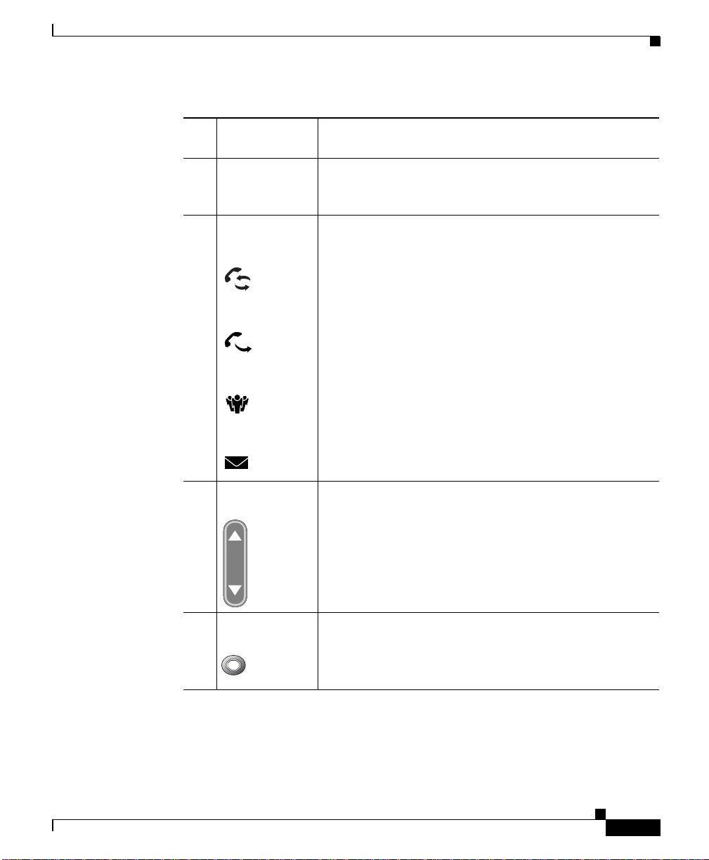
3 Feature buttons
Redial
Enable you to engage the Redial, Transfer, Conference,
and Messages functions.
Transfer
Conference
Messages
4 Volume button Increases or decreases volume for the handset. Also
controls the ring volume (i f on-hook) .
OL-6313-01
5 Hold button Places an active call on hold, resumes a held call, or
switches between an active call and a held
call—depending on the line state.
Cisco IP Phone Administration Guide for Cisco CallManager 3.3, Cisco IP Phones 7902G/7905G/7912G
1-3
Page 28

Chapter1 An Overview of the Cisco IP Phone
Understanding the Cisco IP Phone Models 7905G/7912G
6 Menu button Prov id es access to the Interactive Voice Response (IVR)
system.
7 Keypad W orks exactly like the keypad on a traditional telephone.
8 Handset with
indicator light
Functions like a traditional handset. The light strip at the
top of the ha nds et b l inks wh en the p hone ri ngs a nd
remains lit to indicate a new voice message (depending
on your voice messaging sy stem).
Understanding the CiscoIP Phone Models
7905G/7912G
The Cisco IP Phone models 7905G/7912G are designed primarily to fulfill
requirements for cost-effective IP telephony at the enterprise level, and fo r small
and medium-sized businesses and offices. They also are suita ble for lo cations
where a single-line p hone is ne eded, suc h as cafeter ias, br eak room s, lobbie s, and
manufacturing floors.
1-4
The main compone nts of the Cisco IP Phone models 7905G/7912G a re shown in
Figure 1-2.
Cisco IP Phone Administration Guide for Cisco CallManager 3.3, Cisco IP Phones 7902G/7905G/7912G
OL-6313-01
Page 29
Chapter 1 An Overview of the Cisco IP Phone
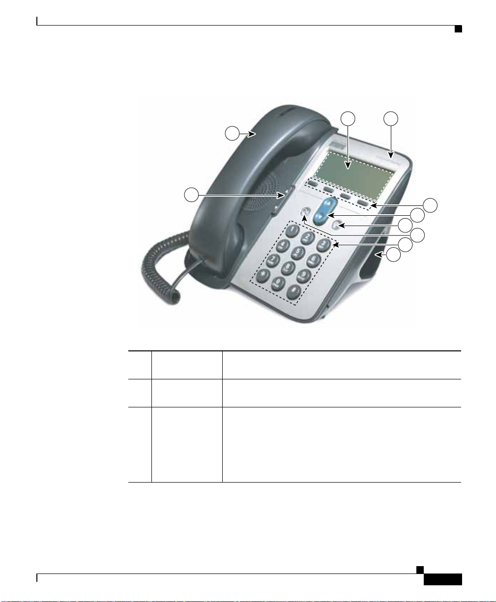
Figure 1-2 Cisco IP Phone Models 7905G/7912 Features
Understanding the CiscoIP Phone Models 7905G/7912G
1 2
9
8
3
4
5
6
7
10
OL-6313-01
1 LCD screen Displays features su ch as the tim e, date, you r phone
number, caller ID, call status, and softkey tabs.
2 Cisco IP Phon e
series type
Indicates the Cisco IP Phone Series to which your phone
belongs.
3 Softkeys Enable you to e ngage any of the func ti ons di spla yed o n
the correspondin g LCD scr een tabs . Softkeys point to
feature option s t hat are displa ye d al ong the bot tom of
your LCD screen. Sof tkey funct ions ch an ge de pend ing
on the status of your phone (for example, if the phone is
active or idle).
Cisco IP Phone Administration Guide for Cisco CallManager 3.3, Cisco IP Phones 7902G/7905G/7912G
91031
1-5
Page 30

Understanding the Cisco IP Phone Models 7905G/7912G
Chapter1 An Overview of the Cisco IP Phone
4 Navigation
button
Enables you to scroll through text and select features
displayed on the LCD screen. Also provides access to
speed dial numbers when there are no text or features to
scroll through.
5 Menu button Displays a menu that provides access to a voice
messaging system, ph one l ogs and dir ectori es, set ting s,
and services.
6 Hold button Puts a current call on hold or ta kes a cal l off hold.
7 Keypad W orks exactly like the keypad on a traditional telephone.
8 Volume button Increases or decreases volume for the handset and
speaker. Also controls the rin ge r volum e (i f o n-h ook) .
1-6
9 Handset Functions like a traditional handse t. The light strip at the
top of the ha nds et b l inks wh en the p hone ri ngs a nd
remains lit to indicate a new voice message (depending
on your voice messaging sy stem).
10 Footstand Allows the phone to stand at a convenient angle on a desk
or table.
Cisco IP Phone Administration Guide for Cisco CallManager 3.3, Cisco IP Phones 7902G/7905G/7912G
OL-6313-01
Page 31

Chapter 1 An Overview of the Cisco IP Phone
What Networking Protocols Are Used?
What Networking Protocols Are Used?
Cisco IP Phones support several industry- st anda rd an d Cisco net working
protocols for voice commu nica tion. Table 1-1 provides an overview of the
networking protocols that the Cisco IP Phon e mode ls 7902G/790 5G/791 2G
supports.
Table 1-1 Supported Networking Protocols on the Cisco IP Phone
Networking Prot ocol Pur pose Usage Notes
Cisco D is cove ry
Protocol (CDP)
Dynamic Host
Configuration Protocol
(DHCP)
CDP is a device-discovery protoc ol t hat
runs on all Cisc o-m anufac tur ed
equipment.
Using CDP, a device can advertise its
existence to other devices and receive
information ab out o the r d evices in th e
network.
DHCP dynamically allocates and assigns
an IP address to network devices.
DHCP enable s you to co nnec t an IP
phone into the net work and have the
phone become ope rationa l without you
needing to manually assign an IP ad dress
or configure additio nal net work
parameters.
The Cisco IP Phone uses CDP to
communicate information such as
auxiliary VLAN ID, per port
power management details, and
Quality of Service (QoS)
configuration information with the
Cisco Catalyst switch.
DHCP is enabled by default. If
disabled, you mu st ma nu ally
configure the IP ad dress, subn et
mask, gateway, and an TFTP
server on each ph one lo ca ll y.
Cisco recommends that you use
DHCP custom option 150. With
this method, you configure the
TFTP server IP address as the
option value. For additional
supported DCHP configurations,
see Cisco CallManager System
Guide.
OL-6313-01
Cisco IP Phone Administration Guide for Cisco CallManager 3.3, Cisco IP Phones 7902G/7905G/7912G
1-7
Page 32

Chapter1 An Overview of the Cisco IP Phone
What Networking Protocol s Are Used?
Table 1-1 Supported Networking Protocols on the Cisco IP Phone (continued)
Networking Prot ocol Pur pose Usage Notes
Internet Protocol (IP) IP is a messaging protocol that addresses
and sends packets across the network.
Real-Time Transport
(RTP)
RTP is a standard for transporting
real-time data, such as interactive voice
and video, over data networks.
Transmission Control
Protocol (TCP)
Trivial File Transfer
Protocol (TFTP)
TCP is a a connection-oriented transport
protocol.
TFTP allows you to transfer f iles ov er the
network.
On the Cisc o IP Phone, TFTP en ab les
you to obtain a conf iguration fi le spec if ic
to the phone type .
User Datagram Protocol
(UDP)
UDP is a connectionless mess aging
protocol for delivery of data packets.
To communicate using IP,
network devices must have an
assigned IP address, subnet, and
gateway.
IP addresses, subnets, and
gateways identifications are
automatically a ssigned if you ar e
using the Cisco IP Phone with
Dynamic Host Configuration
Protocol (DHCP). If you are not
using DHCP , you must manually
assign these properties to each
phone locally.
Cisco IP Phones use the RTP
protocol to send and receive
real-time voice traffic from other
phones and gateways.
Cisco IP Phones use TCP to
connect to Cisco CallManager
and to access XML services.
TFTP requires a TFTP server in
your network, which c an be
automatically identif ied from the
DHCP server. If more than one
TFTP server is runnin g in yo ur
network, you must manuall y
assign a TFTP server to each
phone locally.
Cisco IP Phones receive and
process UDP messages.
1-8
Related Topics
• Modifying DHCP Settings, page 4- 9
• Configuring IP Settings, pa ge 4- 15
Cisco IP Phone Administration Guide for Cisco CallManager 3.3, Cisco IP Phones 7902G/7905G/7912G
OL-6313-01
Page 33

Chapter 1 An Overview of the Cisco IP Phone
What Features are Supported on the CiscoIP Phone Models 7902G/7905G/7912G?
• Configuring TFTP Options, pa ge 4-28
• Understanding Inte racti on s wi th O the r Ci sco I P Telephony Products,
page 2-1
• Understanding the Phone Startup Proc ess, page 2- 4
What Features are Supported on the CiscoIP Phone
Models 7902G/7905G/7912G?
The Cisco IP Phone models 7902G/7905G/7912G function much like traditional
analog phones, al lowing you t o plac e a nd rec eive telephone ca lls.
In addition to traditional telephony featu res, the Cisco IP Phone includes features
that enable you to admi nister an d monitor the phon e as a network device.
This section includes the following topics:
• Feature Overview, page 1-9
• Configuring Telephony Features, page 1-10
• Configuring Network Features Using the Cisc o IP Phone, page 1 -11
• Providing Users with Feature Information, page 1-11
Feature Overview
Cisco IP Phones provide traditional telephony functionality, such as call
forwarding and tra nsf er ring, r edi ali ng , spe ed di al ing, c onf eren ce ca llin g, an d
voice messaging system access. Cisco IP phones also provide a variety of other
features. For an overview telephony features the Cisco IP Phone models
7902G/7905G/7912G sup por t, and f or ti ps o n configurin g t hem , see t h e
“Configuring Telephony Features Using Cisco Ca llMa nage r Ad minist rat ion”
section on page 5-2.
Like other network devices, you must configure the Cisco IP Phon es to prepare
them to access Cisco CallManager and the rest of the IP network. Using DHCP,
you have fewer settings to modify, but you can choose to assign a static IP if your
network requires it. For instructions on configuring the network sett ings on the
Cisco IP Phones, see Chapte r 4, “C onfiguring Network Set tings on the
Cisco IP Phone.”
Cisco IP Phone Administration Guide for Cisco CallManager 3.3, Cisco IP Phones 7902G/7905G/7912G
OL-6313-01
1-9
Page 34

What Features are Supported on the Cisco IP Phone Models 7902G/7905G/7912G?
The Cisco IP Phone models 7905 G/7912G ca n integrate wit h the corp orate
Lightweight Directory Acc ess Protocol 3 (L DAP3) standard directory to ena ble
users to search for co-wo rkers contact information directly from their IP phones.
For information about co nfiguring this feature , see the “ Configuring the
Corporate Directory ” section on pa ge 5-7.
Because the Cisco I P Pho ne i s a network device, y ou can obta in d eta il ed st atu s
information from it dir ectly. This information can assis t you in trouble shooting
any problems users m ig ht en cou nter whe n using the ir IP p hon es. Se e Ch apter 6,
“Troubleshooting the Cisco IP Phone” for tips on u sing this information.
Related Topics
• Configuring Network Setting s on the Ci sco I P Pho ne, pag e 4- 1
• Configuring Users, Featu res, an d Se rvi ces, pa ge 5 -1
• Troubleshooting the Cisco IP Phon e, p age 6-1
Configuring Telephony Features
Chapter1 An Overview of the Cisco IP Phone
1-10
You can modify additional settings from the Cisco CallManager Administration
application. Use this web-based application to set up phone registration criteria
and calling search spaces, to conf igure corpo rate directories, and to mod ify phone
button templates, among other tasks. See the “Configuring Telephony Features
Using Cisco CallManager A dministr ation” secti on on page 5-2 and th e
Cisco CallManager Administration G uide for additional information.
If you are not familiar with the Cisco CallManager Administration application,
use the context-sens itiv e help that is ava ilable within the application for g uidance.
You can access context-sensitive help by choosing Help > For this screen from
the main menu bar.
This guide pr ovides par t ial i ns truc tio ns for proc ed ure s that i nvolve
Cisco C allManager Administration. These instructions are intended to point you
to the appropriate window in the Cisco CallManager application and to provide
some initial guidance.
For detailed information about using Cisco CallManager, refer to the
Cisco C allManager documentation suite that is available at this location:
http://www.cisco.com/univercd/cc/td/doc/product/voice/c_callmg/index.htm
Cisco IP Phone Administration Guide for Cisco CallManager 3.3, Cisco IP Phones 7902G/7905G/7912G
OL-6313-01
Page 35

Chapter 1 An Overview of the Cisco IP Phone
What Features are Supported on the CiscoIP Phone Models 7902G/7905G/7912G?
Related Topic
• Configuring Telephony Features Using Cisco CallManager Administrati on,
page 5-2
Configuring Network Features Using the Cisco IP Phone
You can locally configure fe atur es suc h as DH CP, TFTP, and IP sett ing s on the
phone itself. You can also obtain stati stics ab out a curre nt call or firmware
versions on the phon e.
For more informati on abou t configur ing fea ture s a nd viewing s tat ist ics fro m the
phone, see Chapter 4, “Configuring Network Settings on the Cisco IP Phone” and
Chapter 6, “Troubleshooting the Cisco IP Phone.”
Related Topics
• Configuring Network Setting s on the Ci sco I P Pho ne, pag e 4- 1
• Troubleshooting the Cisco IP Phon e, p age 6-1
Providing Users with Feature Information
If you are a system administrator, you are likely the primary source of information
for Cisco IP Phone users in your networ k or company. To ensure that you
distribute the most current feature and procedural information, familiarize
yourself with Cisco IP Phone document ation. M ake sure to visit the
Cisco IP Phone web site:
http://www.cisco.com/univercd/cc/td/doc/product/voice/c_ipphon/ip_clmgr/engl
ish/index.htm.
From this site, you can view and order various user guides, including wallet cards.
For complete ordering information, see the “Obtaining Documentat ion” sectio n
on page xiv.
In addition to p rovidin g docum en tati on, i t i s impo rta nt t o info rm users of
available Cisco IP Phone features—incl uding fe ature s specific to your co mpany
or network—and of how to access and customize those features, if appropriate.
For a summary of some of the key information that phone users need their system
administrators to provide, see the “Providing Information to Users Via a Web
Site” section on page 5-9.
Cisco IP Phone Administration Guide for Cisco CallManager 3.3, Cisco IP Phones 7902G/7905G/7912G
OL-6313-01
1-11
Page 36

Chapter1 An Overview of the Cisco IP Phone
Understanding the Requirem ents for Installing and Configuring the Cis co IP Phone Models 7902G/7905G/7912G
Related Topic
• Providing Information to U ser s Via a Web Site, page 5-9
Understanding the Requirements for Installin g and
Configuring the Cisco IP Phone Models
7902G/7905G/7912G
To install and configure the Cisc o IP Phon e mo dels 790 2G/790 5G /791 2G, you
must configure some net work se tt ings, set up Ci sco CallManager, and make
changes locally on t he p hon e.
Refer to Table 1-2 for an overview of required proc edur es. For detaile d
information about the se step s, refer to the sources s hown.
Note You can specify additional configuration settings using profile files stored on the
TFTP server. For more information, see Appendi x A, “Additional Configuration
Methods, Parameters, and Procedures.”
Table 1-2 Overview of Configuration Procedures for the Cisco IP Phone
Required Task Purpose For More Information
1. If the Cisco IP Phone model that
you want to configure does not
appear in the Phone Type
drop-down list in
Cisco CallManager, go to the
following URL and install the
latest support patch for you r
version of Cisco CallManager:
http://www.cisco.com/cgi-bin/
tablebuild.pl/callmgr-33
Cisco IP Phone Administration Guide for Cisco CallManager 3.3, Cisco IP Phones 7902G/7905G/7912G
1-12
The support patch all ows
Cisco CallManager to identif y
a Cisco IP Phone.
Refer to instructions on the
same web page as the
support patch.
OL-6313-01
Page 37

Chapter 1 An Overview of the Cisco IP Phone
Understanding the Requirements for Installing and Configuring the Cisco IP Phone Models 7902G/7905G/7912G
Table 1-2 Overview of Configuration Procedures for the Cisco IP Phone (continued)
Required Task Purpose For More Information
2. Gather the following information
about the pho ne:
• Model
• MAC address
• Physical location of the phone
• Cisco CallManager user to
associate with the phone
• Partition, calling search space,
and location information, if
used
• Number of lines and
associated directory numbers
to assign to th e pho ne
• Features to be added and
configured to the phone
3. Configure routers, gateways, and
switches to handl e voice
communication.
4. Add the phone to
Cisco CallManager.
Required to configure
Cisco CallManager to support
the Cisco IP Phones.
Establishes the infrastructure
for the IP tel ephony ne twork .
Provides call processing in th e
IP telephony network.
See the following:
• “Adding Phones to the
Cisco CallManager
Database” section on
page 2-12
• “Configuring
Telephony Features
Using
Cisco CallManager
Administration” section
on page 5-2
• Cisco CallManager
System Guide
• Cisco CallManager
Administration Guide
See the “Understanding
How the Cisco IP Phone
Interacts with the
Cisco Cat aly st Fam ily of
Switches” section on
page 2-3 and the
documentation inclu ded
with these devices.
See the “Adding Phones to
the Cisco Call Man ager
Database” section on
page 2-12 and refer to
Cisco CallManager
Administration Guide.
OL-6313-01
Cisco IP Phone Administration Guide for Cisco CallManager 3.3, Cisco IP Phones 7902G/7905G/7912G
1-13
Page 38

Chapter1 An Overview of the Cisco IP Phone
Understanding the Requirem ents for Installing and Configuring the Cis co IP Phone Models 7902G/7905G/7912G
Table 1-2 Overview of Configuration Procedures for the Cisco IP Phone (continued)
Required Task Purpose For More Information
5. Choose to auto-register p hon es,
add them to the Cisco CallManager
database manual ly, or use the
Bulk Administration T ool (BA T) to
Determines how the phone is
added to Ci sc o C al l Manager
and how the directory number
is assigned.
add many phones to t he data base
simultaneously.
6. Choose to power through the
Cisco AC adapter or
Cisco Catalyst switch.
Determines whether the phone
receives power from an
external power source over a
power cor d or from the in-l i n e
power source over the Ethernet
cable.
7. Install the phone in the n etwork. Adds the phone to the network. See Chapter 3, “Installing
8. Configure network settings on the
Cisco IP Phone.
Sets IP settings (if not using
DHCP in the network) and
assigns a TFTP server.
9. Configure the phone features such
as call waiting, call forward, call
Provides enhanced telephony
functionality.
park, and call pickup.
10. C onfigure dir ectori es.
Note This task does not appl y to the
Cisco IP Phone 7902G.
Integrates with a LDAP3
standard d i rect or y, enablin g
users to se ar ch thr oug h a
corporate directory.
See the “Adding Phones to
the Cisco Call Man ager
Database” section on
page 2-12 and refer to
Cisco CallManager
Administration Guide.
See the “Provi ding Pow er to
the Cisco IP Phone” section
on page 2-9 or the
documentation inclu ded
with the Cisco Catalyst
switch.
the Cisco IP Phone”.
See the “Configuring IP
Settings” section on
page 4-15 and the
“Configuring TFTP
Options” section on
page 4-28.
See the “Configuring
Telephony Features Usi ng
Cisco CallManager
Administration” sect ion on
page 5-2 and refer to
Cisco CallManager
Administration Guide.
See the “Configuring the
Corporate Directory”
section on page 5-7 or refer
to Cisco CallManager
Administration Guide.
1-14
Cisco IP Phone Administration Guide for Cisco CallManager 3.3, Cisco IP Phones 7902G/7905G/7912G
OL-6313-01
Page 39

Chapter 1 An Overview of the Cisco IP Phone
Understanding the Requirements for Installing and Configuring the Cisco IP Phone Models 7902G/7905G/7912G
Table 1-2 Overview of Configuration Procedures for the Cisco IP Phone (continued)
Required Task Purpose For More Information
11. Configure Cisco IP Phone services.
Note This task does not appl y to the
Cisco IP Phone 7902G.
Allows users to quickly access
information such as weather
quotes, stocks quotes, or other
web-based information that
uses extensible-markup
language (XML).
12. C onfigure dir ectorie s.
Note This task does not appl y to the
Cisco IP Phone 7902G.
13. A d d u ser s to C is co CallManag er. Associ at es a use r w ith a
Integrates with an LDAP3
standard d i rect or y, enablin g
users to se ar ch thr oug h a
corporate directory.
phone, enabling access to the
User Options web-based
application where users set up
features suc h as cal l
forwarding and speed dial, and
subscribe to services.
14. Pr ovide in forma tion to e nd use rs
about how to use their phone s and
how to configure their phone
options.
Ensures that users have
adequate information to
successfully use their
Cisco IP Phones .
See the “Setting U p
Services” section on
page 5-8 and refer to
Cisco CallManager
Administration Guide.
See the “Configuring the
Corporate Directory”
section on page 5-7 and
refer to Cisco CallManager
Administration Guide.
See the “Adding Users to
Cisco CallManager” section
on page 5-7 and refer to
Cisco CallManager
Administration Guide or the
Cisco CallManager
application online help.
See the “Providing
Information to Users Via a
Web Site” section on
page 5-9.
OL-6313-01
Cisco IP Phone Administration Guide for Cisco CallManager 3.3, Cisco IP Phones 7902G/7905G/7912G
1-15
Page 40

Chapter1 An Overview of the Cisco IP Phone
Understanding the Requirem ents for Installing and Configuring the Cis co IP Phone Models 7902G/7905G/7912G
1-16
Cisco IP Phone Administration Guide for Cisco CallManager 3.3, Cisco IP Phones 7902G/7905G/7912G
OL-6313-01
Page 41

CHAPTER
2
Preparing to Install the Cisco IP Phone
on Your Network
Cisco IP Phones enable you to communicate using voice over a data network. To
provide this capability, the IP Phones depend upon and interact with se v eral o ther
key Cisco IP Telephony components, inclu ding Ci sco Call Man ager.
These sections provid e you with an important o vervie w of the interaction betwe en
the Cisco IP Phone models 7902G/7905G/7912G and other key components of the
Voi ce over IP ( VoIP) network:
• Understanding Inte racti on s wi th O the r Ci sco I P Telephony Products,
page 2-1
• Understanding the Phone Startup Proc ess, page 2- 4
• Guidelines for Configuring Ports on the Cisco IP Phone models
7902G/7905G/7912G, pa ge 2-8
• Adding Phones to the Cisco Ca llMa nager Da tab ase, page 2 -12
Understanding Interactions with Other
Cisco IP Telephony Products
To function in the IP telephony network, the C isco IP Phone mu st be connecte d
to a networking device, such as a Cisco Catalyst switch. You must also register
the Cisco IP Phone with a Cisco CallMan ager sy stem befo re send ing and
receiving calls.
Cisco IP Phone Administration Guide for Cisco CallManager 3.3, Cisco IP Phones 7902G/7905G/7912G
OL-6313-01
2-1
Page 42

Chapter2 Preparing to Install the Cisco IP Phone on Your Network
Understanding Interactions with Other Cisco IP Telephony Products
This section covers the following topics:
• Understanding How the Cisco IP Phone Interacts with Cisco CallManager,
page 2-2
• Understanding How the Cisco IP Phone Interacts with t he Cisco Ca talyst
Family of Switches, page 2-3
Understanding How the Cisco IP Phone Interacts with
Cisco CallManager
Cisco CallManager is an open and indust ry-stand ard cal l processing system.
Cisco CallManager software runs on a Windows 2000 server and sets up and tears
down calls between phones, integrating traditional PBX functionality with the
corporate IP network. Cisco CallManager manages the components of the IP
telephony system—the phones, access gateways, and the resources necessary for
such features as call co nfere ncing a nd route pl anning .
For information about configuring Cisco CallManager to work with the I P devices
described in this chapter, refer to Cisco CallManager Administration Guide and
Cisco CallManager System Guide.
2-2
Note If the Cisco IP Phon e mo de l tha t yo u want to c onfigure does no t appe ar i n the
Phone Type drop-down list in Cisco CallManager, go to the following URL and
install the latest suppor t p atc h for yo ur version of Cisc o CallM ana ger:
http://www.cisco.com/cgi-bin/tablebuild.pl/callmgr-33
Related Topic
• Configuring Telephony Features Using Cisco CallManager Administrati on,
page 5-2
Cisco IP Phone Administration Guide for Cisco CallManager 3.3, Cisco IP Phones 7902G/7905G/7912G
OL-6313-01
Page 43

Chapter 2 Preparing to Install the Cisco IP Phone on Your Network
Understanding Interactions with Other Cisco IP Telephony Products
Understanding How the Cisco IP Phone Interacts with the
Cisco Catalyst Family of Switches
The Cisco IP Phone 7912G has an inte rn al Ethe rn et sw itch, enabl ing it to switch
incoming traffic to the phone, the access port, or to the network port (see the
“Connecting to the Network” section on page 2-8 for details). The Cisco IP Phone
models 7902G/7905G do not include an internal Ethernet switch or an access port.
If a computer is connected to the access port, the computer and the phone share
the same physical link to the switch and the same port on the switch.
This shared physical link has the foll owing implicati ons for the VLAN
configuration on the n etwor k:
• The current VLANs mi ght be configure d on an IP subnet ba sis. However,
additional IP addre sses may not be available to assign the phone to the same
subnet as other devices connected t o the same port .
• Data traff ic present on the VLAN suppor ting phones might reduce the quality
of Voice-over-IP traffic.
You can resolve these issues by isolating the voice traffic onto a separate VLAN
on each of the ports connecte d to a phone. The switch port configure d for
connecting a phone wou ld have separate VLAN s configured for carr ying:
OL-6313-01
• Voice tra ffic to and from the IP phone (a uxiliary VLAN)
• Data traffic to and from the PC connected to the switch through the access
port of the IP p hon e (n ative VLAN )
Isolating the phones on a separate, auxiliary VLAN increases the quality of the
voice traffic and allows a large number of phones to be added to an existing
network where the r e ar e not en oug h I P a dd resses.
For more information, refer to the documentation included with the
Cisco C atalyst switch.
Related Topics
• Connecting to the Network, page 2-8
• Understanding the Phone Startup Proc ess, page 2- 4
• Modifying VLAN Settings, page 4-24
Cisco IP Phone Administration Guide for Cisco CallManager 3.3, Cisco IP Phones 7902G/7905G/7912G
2-3
Page 44

Chapter2 Preparing to Install the Cisco IP Phone on Your Network
Understanding the Phone Startup Process
Understanding the Phone Startup Process
When connecting t o t he VoIP network, the Cisco IP Phone go es thro ugh a
standard startup pro cess co mpos ed of u p to seven steps. De pendi ng on y our
specific network configuration, not all of the se step s may occur on yo ur
Cisco IP Phone.
Each of these steps is described in the sections that follow:
• Obtaining Power from the Swit ch, page 2- 4
• Loading the St ored Phon e Imag e, p age 2-5
• Configuring VLAN, page 2-5
• Obtaining an IP Address, pag e 2-5
• Accessing TFTP Server, page 2-6
• Requesting Configuration Files, page 2-6
• Contacting Cisco CallManager, page 2-7
Related Topics
• Verifying the Phone Startup Process, pa ge 3 -9
• Resolving Startup Problems, page 6-12
Obtaining Power from the Switch
You can connect the Cisco IP Phone to a Cisco Catalyst switch with on e of the
modules that provid es power to t he p hon e (W S-X634 8-R J45V ) . See the
“Providing Power to the Ci sco I P Pho ne” se ction on pa ge 2 -9 fo r details .
If you use this opti onal co nfigura ti on, t he p hon e rece ives phan tom power an d
powers up when you connect the Cisco IP Phone t o the switc h. The phone then
sends Cisco Discovery Protocol (CDP) notifications to the switch indicating it is
ready to receive CDP packets and indicating the power requirement for the phone.
The switch allocates power an d sends it over the network cabl e.
Cisco IP Phone Administration Guide for Cisco CallManager 3.3, Cisco IP Phones 7902G/7905G/7912G
2-4
OL-6313-01
Page 45

Chapter 2 Preparing to Install the Cisco IP Phone on Your Network
Related Topics
• Understanding the Phone Startup Proc ess, page 2- 4
• Providing Power to the Cisco IP Phone, page 2 -9
• Resolving Startup Problems, page 6-12
Loading the Stored Phone Image
The Cisco IP Phone h as non -volatile Fla sh m emor y in whi ch it store s firmware
images and user-defined preferences. At startup, the phone runs a bootstrap loader
that loads a phone image stored in Flash memory. Using this image, the phone
initializes its software and hardware.
Related Topics
• Understanding the Phone Startup Proc ess, page 2- 4
• Resolving Startup Problems, page 6-12
Understanding the Phone Startup Process
Configuring VLAN
If the Cisco IP Phone is connected to a Cisco Catalyst switch, the switch next
informs the phone of the voice VLAN defined on the switch. The phone nee ds to
know its VLAN membership before i t can procee d with the Dyn amic H ost
Configuration Protocol (DHCP) request for an IP address.
Related Topics
• Understanding the Phone Startup Proc ess, page 2- 4
• Modifying VLAN Settings, page 4-24
• Resolving Startup Problems, page 6-12
Obtaining an IP Address
If the Cisco IP Phone is using DHCP to obtain an IP address, the phone querie s
the DHCP server to obtain one . If you ar e not u sing D HC P in you r net work, yo u
must assign static IP addresses to each phone locally.
Cisco IP Phone Administration Guide for Cisco CallManager 3.3, Cisco IP Phones 7902G/7905G/7912G
OL-6313-01
2-5
Page 46

Understanding the Phone Startup Process
Related Topics
• Understanding the Phone Startup Proc ess, page 2- 4
• Modifying DHCP Settings, page 4- 9
• Configuring IP Settings, pa ge 4- 15
• Resolving Startup Problems, page 6-12
Accessing TFTP Server
In addition to assigning an IP addr ess, the DHCP server dire cts the
Cisco IP Phone to a TFTP Server. If the phone has a statically defined IP address,
you must configure the TFTP server locally on the phone; the phone then contacts
the TFTP server directly.
Related Topics
• Understanding the Phone Startup Proc ess, page 2- 4
• Configuring TFTP Options, pa ge 4-28
Chapter2 Preparing to Install the Cisco IP Phone on Your Network
• Resolving Startup Problems, page 6-12
Requesting Configuration Files
The TFTP server ha s co nfigura tion files ( .cnf file for ma t o r . cnf. xm l) f or
telephony devices, which define parameters for connecting to Cisco CallManager.
In general, any t ime you ma ke a chan ge in Ci sco C al lM an ager t hat requ i res the
phone (device) to be re set, a cha nge has b ee n ma de to the p hone' s con figurat ion
file.
The .cnf.xml file also contains the information that tells the phone which image
load it should be running. If this image load differs from the one currently loaded
on the phone, the phone cont acts th e TFTP server to re quest the new image file.
The phone first requests the file SEPxxxxxxxxxxxx.cnf.xml, where each xx is the
two-digit lowercase hexadecimal representation of each integer in the phone’s
MAC address. If the phone cannot find this file, it requests th e files
XMLDefault.cnf.xm l and SEDDefa ult.cnf.
Cisco IP Phone Administration Guide for Cisco CallManager 3.3, Cisco IP Phones 7902G/7905G/7912G
2-6
OL-6313-01
Page 47

Chapter 2 Preparing to Install the Cisco IP Phone on Your Network
After the phone ob tains one of t he .c nf .xml files or t he . c nf file, the
Cisco IP Phone 7902G request s the profile file ffxxxxxxxxxxxx, the
Cisco IP Phone 7905G requests th e profile file ldxxxxxxxxxxxx, and the
Cisco IP Phone 7912G requests the profile file gkxxxxxxxxxxxx, where each xx is
the two-digit lowercase hexadecimal representation of each integer in the phone’s
MAC address. If a phone can not find this pro file file, i t r eq uest s th e p rofile file
ffdefault.cfg for the Cisco IP Ph one 7902 G, the profile file lddefault .cfg for the
Cisco IP Phone 7905G, or the profile file gkdefault.cfg for t he Cisco IP Phone
7912G. For more informati on about profile files, see Appendi x A, “Additional
Configuration Methods, Paramete rs, and Procedu res.”
After the phone finds one of the profile files, or if it cann ot find a profile file, it
continues with its startup process.
Related Topics
• Understanding the Phone Startup Proc ess, page 2- 4
• Resolving Startup Problems, page 6-12
Contacting Cisco CallManager
Understanding the Phone Startup Process
OL-6313-01
The configuration file de fines how the Cisco I P Pho ne com mun ica tes with
Cisco C allManager. After obtaining the file from the TFTP server, the phone
attempts to make a TCP connec tio n to the h ig hes t p rior ity Ci sco CallManager on
the list.
If the phone was manually added to the database, Cisco CallManager identifies
the phone. If t he p hon e was no t manu all y ad ded to t he dat aba se and
auto-registration is enabled in Cisco CallManager, the phone attempts to
auto-register itself in the Cisco CallManager database.
Cisco CallManager informs devices using .cnf format configuration files of their
load ID. Devices using .xml format configuration files receive the load ID in the
configuration file.
Related Topics
• Understanding the Phone Startup Proc ess, page 2- 4
• Resolving Startup Problems, page 6-12
Cisco IP Phone Administration Guide for Cisco CallManager 3.3, Cisco IP Phones 7902G/7905G/7912G
2-7
Page 48

Chapter2 Preparing to Install the Cisco IP Phone on Your Network
Guidelines for Configu ring Ports on the Cisco IP Phone mode ls 7902G/7905G/7912G
Guidelines for Configuring Ports on the
Cisco IP Phone models 7902G/7905G/7912G
Cisco IP Phones includ e ports for co nnectin g the pho nes to the net work and for
providing power to the phones. These sections provide tips for configuring these
ports:
• Connecting to the Network, page 2-8
• Providing Power to the Cisco IP Phone, page 2 -9
Connecting to the Network
The Cisco IP Phone 7912G has two RJ-45 ports labelled “network” and “access.”
The Cisco IP Phone m odels 7 902G/7 905G have one RJ- 45 por t. Ea ch p ort
supports 10/100 Mbps half - or full-dup lex connect ions to exter nal devices. You
can use either Category 3 or 5 cabling for 10-Mbps connections, but you must use
Category 5 for 100 Mbps conne ct ions. On both the network port and access port,
use full-duplex mode to avoid collisions.
See Figure 3-1 for the connec tion por ts available on the back of the Ci sco IP
Phone models 7902G/7905G. See Figure 3-2 for the connectio n ports a vail able on
the back of the Cisco I P Ph one 7912 G
Related Topics
• Connecting the Cisco IP Phone to the Network, pa ge 3-4
• Using the Network Port, page 2-8
• Using the Access Port, page 2-9
Using the Network Port
Use the network port to conne ct the phone to the network. You must use a
straight-through ca ble o n th is po rt. The ph one c an al so obtai n inl ine power from
the Cisco Catalyst switch over this connection. See the “Providing Power to the
Cisco IP Phone” se ction on page 2-9 for detail s.
Cisco IP Phone Administration Guide for Cisco CallManager 3.3, Cisco IP Phones 7902G/7905G/7912G
2-8
OL-6313-01
Page 49

Chapter 2 Preparing to Install the Cisco IP Phone on Your Network
Guidelines for Configuring Ports on the Cisco IPPhone models 7902G/7905G/7912G
Related Topics
• Connecting the Cisco IP Phone to the Network, pa ge 3-4
• Providing Power to the Cisco IP Phone, page 2 -9
Using the Access Port
Use the access port to con nect a network devi ce, such as a compute r , to the phone.
You must use a straight-through cable on this port.
Related Topic
• Connecting the Cisco IP Phone to the Network, pa ge 3-4
Providing Power to the Cisco IP Phone
You can power a Cisco IP Phone f rom a n extern al p ower suppl y, from a switch
port, or from a power source between the pho ne and the swit ch.
The Cisco IP Phone can b e powered by the following sources :
OL-6313-01
• External power—optiona l Cisco AC adapter and power cord fo r conne cting
to a standard wall receptacle.
• Inline power—inline power pr ovider to th e Cisco IP Phone when co nne cte d
to a Cisco Catalyst switch capable of providing inline power.
Note Only the network port supports in line power from the
Cisco Catalyst switches.
• WS-PWR-PANEL—power patch panel t hat allows the Cisc o IP Pho ne to be
connected to existing Catalyst 400 0, 5000, and 60 00 family 10/1 00BaseTX
switchi ng modules.
This module sends power on pins 4, 5, 7, & 8, which are not used for Ethernet
signaling. The power patch panel also attempts to verify that the attached
device is a Cisco IP Phone before providing power.
Cisco IP Phone Administration Guide for Cisco CallManager 3.3, Cisco IP Phones 7902G/7905G/7912G
2-9
Page 50

Chapter2 Preparing to Install the Cisco IP Phone on Your Network
Guidelines for Configu ring Ports on the Cisco IP Phone mode ls 7902G/7905G/7912G
Related Topics
• Connecting the Cisco IP Phone to the Network, pa ge 3-4
• Connecting to the Network, page 2-8
• Understanding Inte racti on s wi th O the r Ci sco I P Telephony Products,
page 2-1
• Power Source Design, page 2-10
• Redundancy Feature, page 2-11
Power Source Design
The phone and switch automatically determine which power source the phone
uses. If the power has to be switched to a different source, the phone user will
experience different results based on which power source is being used by the
phone.
Use the following in for mat ion t o choo se a power sou rce for t h e phone :
• If you plug a phone into the optional pow er supply before plugging it in to the
network, the phone is powered by the power supply.
• If you then unplug the phon e fr om the power suppl y, the phone resets. If th e
switch port is configured for 10/ 100 Mbp s, t he swi tch re co gniz es the lo ss of
power and brings t he phon e ba ck u p.
2-10
• If the switch port is configure d f or 10 M bps on ly, then you must u nplug the
network connection an d p lug i t ba ck i nto t he p hone for t he s wit ch t o
recognize the p hone’s loss of power.
• If, however, you plugged the network co nne ctio n in to the p hon e be for e yo u
plugged in the power cord, the phone receives power through the switch, and
unplugging the power co rd w ill n ot b ri ng down the p hon e. I f the sw itch
reboots, the phone will then be powered by the power cord.
Related Topics
• Connecting the Cisco IP Phone to the Network, pa ge 3-4
• Connecting to the Network, page 2-8
• Understanding Inte racti on s wi th O the r Ci sco I P Telephony Products,
page 2-1
• Providing Power to the Cisco IP Phone, page 2 -9
Cisco IP Phone Administration Guide for Cisco CallManager 3.3, Cisco IP Phones 7902G/7905G/7912G
OL-6313-01
Page 51

Chapter 2 Preparing to Install the Cisco IP Phone on Your Network
Guidelines for Configuring Ports on the Cisco IPPhone models 7902G/7905G/7912G
Redundancy Feature
For redundancy, you can use the Cisco AC adapter even if you are using inline
power fr om the Cisco Cataly st s wi t ches . T he C is c o IP Phone can shar e the power
load being used from the inline power and external power source. If either the
inline power or the exte rnal powe r goes do wn, the phone c an switch entirely to the
other power source.
To use this re dund ancy fe a ture :
1. Set the inline power mode to auto on the Cisco Catalyst switch.
2. Connect the unpowered Cisco IP Phon e to the ne twork.
3. Connect the external power supply to the phone afte r the phone powers up.
Related Topics
• Connecting the Cisco IP Phone to the Network, pa ge 3-4
• Connecting to the Network, page 2-8
• Understanding Inte racti on s wi th O the r Ci sco I P Telephony Products,
page 2-1
• Providing Power to the Cisco IP Phone, page 2 -9
Connecting a Handset to a Cisco IP Phone
Each Cisco IP Phone includes a handset designed especially for use with the
phone. These h andse ts a re i nte rcha ngea ble a mong Ci sco I P Pho ne mo de ls. The
handsets include a light str ip used to indi cate voice messa ges waiting.
T o pl ace and answer calls u sing a h andset, plug th e includ ed ha ndset in to the ba ck
of the phone ba se (see the “ Connect ing the Cisco IP Phone t o the Network”
section on page 3-4 for details) and pick up the handset.
Cisco IP Phone Administration Guide for Cisco CallManager 3.3, Cisco IP Phones 7902G/7905G/7912G
OL-6313-01
2-11
Page 52

Chapter2 Preparing to Install the Cisco IP Phone on Your Network
Adding Phones to the Cisco Call Manager Database
Adding Phones to the Cisco CallManager Database
Before installing any Cisco IP phones, you must ma ke decisions about how you
want the phones to be added to the Cisco CallManager database. Because
Cisco C allManager handles call processing in the network, this is a critical step.
You can add phones to the Cisco CallMana ger dat abase au tomat ically us ing
auto-registration, manually using the Cisco CallManager Administration
application, or in groups with the Bulk Administration Tool (BAT).
Once you add a Cisco IP phone using the Cisco Cal lManage r Administra tion
application, the Phone Configuration Window in the application displays the
device name, registration status, and the IP ad dress of the Cisco CallMa nager to
which the device is registered.
This section covers the following topics:
• Using Auto-Registration, page 2-12
• Adding Phones Manual ly, page 2-14
• Using the Bulk Administrati on Tool, page 2-17
Tip To get help using the Cisco CallManager application, access context-sensitive
help by choosing Help > For this page from the main menu bar. F or complete
instructions and co nc ep tual i nfo rmat ion, r efer to Ci sco Call Manager
Administration Guide and Cisco CallManager System Guide.
Using Auto-Registration
Use auto-registration if you w ant Cisco CallManag er to a ssign direc tory number s
automatically to ne w p hones as they connect to the I P te lep hony network. Once a
phone has auto-r egistere d, yo u ca n m ove it to a new loc at ion a nd a ssign i t to a
different device pool wi thout affect ing i ts d ir ector y n um be r.
With auto-registration enabled, Cisco CallManager begins the automatic startup
process to obtain a d irec tor y n umber a s s oon as y ou co nnect the Cisco IP Ph one
to the network. During auto-registration, Cisco CallManager automatically
assigns the next available sequential di rector y number to the phone.
Cisco IP Phone Administration Guide for Cisco CallManager 3.3, Cisco IP Phones 7902G/7905G/7912G
2-12
OL-6313-01
Page 53

Chapter 2 Preparing to Install the Cisco IP Phone on Your Network
Use auto-registration to quickly get all phones into the Cisco CallManager
database. You can then modify any settings, such as the direct ory numbers, from
Cisco CallManager. If you do not use auto-regist ration, you must manua lly add
phones to the Cisc o Ca llMa nager d ata base or us e th e Bulk Adm in istra tion Tool
(BAT ).
Use the following procedure a s a starting po int to enabl e auto -registrat ion using
the Cisco CallManager Administration application. For additional information,
access context-sensitive help from the application or refer to Cisco CallManager
documentation.
Procedure
Step 1 Log in to the Cisco CallManager Administration application.
Step 2 From the menu bar, choose System > Cisco CallManager.
The Cisco Call Man ager Configurat ion win dow appear s.
Step 3 Verify that the “Auto-registration disabled on this Cisco CallManager” setting is
not checked. Cisco CallManager disables the auto-registration by default to
prevent unauthorized connections to the network.
Adding Phones to the Cisco CallManager Database
OL-6313-01
Step 4 To modify phone settings, choose Device > Phone. Use the Find and List Phones
window to enter search criteria for each phone.
Step 5 Install the phone by following the instructions in Chapter 3, “Installing the
Cisco IP Phone.”
Step 6 To configure additional phone features, see the “Configuring Telephony Features
Using Cisco CallManager A dministr ation” secti on on page 5-2 for details.
Related Topics
• Adding Phones Manual ly, page 2-14
• Using the Bulk Administrati on Tool, page 2-17
• Configuring Telephony Features Using Cisco CallManager Administrati on,
page 5-2
Cisco IP Phone Administration Guide for Cisco CallManager 3.3, Cisco IP Phones 7902G/7905G/7912G
2-13
Page 54

Adding Phones to the Cisco Call Manager Database
Adding Phones Manually
If you want to assign spe cific dir ector y n um bers t o a sp eci fic Cisco IP Phone
without using auto-r egistrati on, you can ma nual ly add ea ch phone to the
Cisco CallManager database or use the Bulk Administ ration Tool (BAT).
If you want to add phone s manua lly, and are not us ing Dyna mic Host
Configuration Protocol (DHCP) in your network, then you must configure the IP
settings and Trivial File Transfer Protocol (TFTP) server locally on each phon e.
Alternatively, if you use DHCP, but want to manually set the TFTP server, then
allow the phone to start up, using DHC P, before re-assigning the TFTP server.
See these topics for mor e info rmati on:
• Adding Phones Manual ly U sing DH CP, page 2-14
• Assigning Static IP Add resses , p age 2- 15
Adding Phones Manually Using DHCP
If you are using D HCP i n yo ur ne twork , but you a re n ot u sin g au to-regist rat ion,
you can manually add a phone to the Cisco CallManager database. If you are
using DHCP, you do not need to a ssign IP addre sses o r TFTP servers.
Use the following procedure as a starting point to add phones manually using the
Cisco C allManager Administration application.
Chapter2 Preparing to Install the Cisco IP Phone on Your Network
2-14
Procedure
Step 1 Log in to the Cisco CallManager Administration application.
Step 2 From the menu bar, choose Device > Add a New Device.
The Add a New Device window appears.
Step 3 Select Phone from the Device Type drop-down menu and c lick Ne x t .
The Add a New Phone window appears.
Step 4 Select a phone typ e fr om t he d rop -down m enu and c lick Next.
The Phone Configuration window appears. The fields displayed in this window
depend upon the phone type sele cted.
Cisco IP Phone Administration Guide for Cisco CallManager 3.3, Cisco IP Phones 7902G/7905G/7912G
OL-6313-01
Page 55

Chapter 2 Preparing to Install the Cisco IP Phone on Your Network
Step 5 In the Phone Configuration window, you must enter information in the following
fields:
• MAC Address
• Device Pool
Step 6 Click Insert.
The Cisco C allManager Administration application asks if you want to assign a
directory number.
Step 7 To configure additional phone features, see the “Configuring Telephony Features
Using Cisco CallManager A dministr ation” secti on on page 5-2 for details.
For additional information, access context-sensitive help from the application or
refer to Cisco CallManager documentation.
Related Topics
• Using Auto-Registration, page 2-12
• Assigning Static IP Add resses , p age 2- 15
Adding Phones to the Cisco CallManager Database
• Using the Bulk Administrati on Tool, page 2-17
• Configuring Telephony Features Using Cisco CallManager Administrati on,
page 5-2
Assigning Static IP Addresses
If you do not use DHCP in your network, you must assign st atic IP addresse s to
each phone. You must configure each phone lo ca lly.
Use the following procedure as a starting point to add phones manually using the
Cisco C allManager Administration application.
Procedure
Step 1 Log in to the Cisco CallManager Administration application.
Step 2 From the menu bar, choose Device > Add a New Device.
The Add a New Device window appears.
Cisco IP Phone Administration Guide for Cisco CallManager 3.3, Cisco IP Phones 7902G/7905G/7912G
OL-6313-01
2-15
Page 56

Adding Phones to the Cisco Call Manager Database
Step 3 Select Phone from the Device Type drop-down menu and c lick Ne x t .
The Add a New Phone window appears.
Step 4 Select a phone typ e fr om t he d rop -down m enu and c lick Next.
The Phone Configuration window appears. The fields displayed in this window
depend upon the phone type sele cted.
Step 5 In the Phone Configuration window, enter information in the following fields:
• MAC Address
• Device Pool
Step 6 Click Insert.
The Cisco C allManager Administration application asks if you want to assign a
directory number.
Step 7 Enter information in the required fields.
Step 8 Install the phone by following the instructions in the Chapter 3 , “Installing the
Cisco IP Phone.”
Step 9 Configure the IP settings by following the instructions in the “Configuring IP
Settings” section on page 4-15.
Chapter2 Preparing to Install the Cisco IP Phone on Your Network
2-16
Step 10 Configure the TFTP server by following the instructions in the “Configuring
TFTP Options” se cti on on pa ge 4-28.
Step 11 To configure additional phone features, see the “Configuring Telephony Features
Using Cisco CallManager A dministr ation” secti on on page 5-2 for details.
Related Topics
• Using Auto-Registration, page 2-12
• Adding Phones Manual ly U sing DH CP, page 2-14
• Using the Bulk Administrati on Tool, page 2-17
• Configuring Telephony Features Using Cisco CallManager Administrati on,
page 5-2
Cisco IP Phone Administration Guide for Cisco CallManager 3.3, Cisco IP Phones 7902G/7905G/7912G
OL-6313-01
Page 57

Chapter 2 Preparing to Install the Cisco IP Phone on Your Network
Using the Bulk Administration Tool
The Cisco Bulk Administra tion Tool (BAT) is a plug-i n applica tion for
Cisco C allManager that enables system administrators to perform batch
operations, including registrati on, on large numbers of Cisc o IP Phones.
Refer to Bulk Administration Tool Guide for Cisco CallManager for information
about using BAT in your network.
Related Topics
• Using Auto-Registration, page 2-12
• Adding Phones Manual ly, page 2-14
• Configuring Telephony Features Using Cisco CallManager Administrati on,
page 5-2
Adding Phones to the Cisco CallManager Database
OL-6313-01
Cisco IP Phone Administration Guide for Cisco CallManager 3.3, Cisco IP Phones 7902G/7905G/7912G
2-17
Page 58

Adding Phones to the Cisco Call Manager Database
Chapter2 Preparing to Install the Cisco IP Phone on Your Network
2-18
Cisco IP Phone Administration Guide for Cisco CallManager 3.3, Cisco IP Phones 7902G/7905G/7912G
OL-6313-01
Page 59

CHAPTER
3
Installing the Cisco IP Phone
These topics help you install the Cisco IP Phone on an IP telepho ny network:
• Before You Begin, page 3- 1
• Connecting the Cisco IP Phone to the Network, pa ge 3-4
• Mounting the Phone to the Wall, page 3-8
• Verifying the Phone Startup Process, pa ge 3 -9
• Configuring Startup Network Settings, pag e 3-10
Note For each Cisco IP phone tha t y ou inst all in your ne twork , you m ust first ma ke
some critical decisio ns about how to configure t he phone in yo ur network . You
can then safely install the phone and verify its functionality. For information on
preparing to install, see Chapter 2, “Prepa ring t o In st all t he Ci sco I P Pho ne on
Your Network.”
Before You Begin
Before installing the Cisco IP Phone, review the requirements in these sections:
• Network Requirements, page 3-2
• Cisco C allManager Configuration, page 3-2
• Safety, page 3-3
Cisco IP Phone Administration Guide for Cisco CallManager 3.3, Cisco IP Phones 7902G/7905G/7912G
OL-6313-01
3-1
Page 60

Before You Begin
Network Requirements
For the Cisco IP Phone to successfully operate a s a Cisco IP Phone endpo int in
your network, your network must me et the fo llowing require ments:
• Working VoIP Network
–
Voi ce over IP (VoIP) configured on your Cisco routers and gateways
–
Cisco CallManage r Re lea se 3 .3 or high er ins ta ll ed i n you r net work an d
configured to handle ca ll proce ssing
• IP network that supports DHCP or manual assignment of IP address, gateway,
and subnet mask
Cisco CallManager Configuration
The Cisco IP Phone requires Cisco CallManager to handle call processing. Refer
to the Cisco CallManager Administ ration Guide or context-sensitive help in the
Cisco C allManager application to ensure that Cisco CallManager is set up
properly to manage the phone and to prope rly rout e and proce ss calls .
Chapter 3 Installing the Cisco IP Phone
3-2
If you plan to use auto-registration, verify that it is enabled and properly
configured in Cisco Call Manage r before connec ting any Cisco IP Phone to the
network. See the “Using Auto-R egistration ” section on pa ge 2-12 for details.
You must use Cisco CallManager to configure and assign telephony features to
the Cisco IP Phones. See t he “ Configuring Telephony Features Using
Cisco C allManager Administration” section on page 5-2 for details.
In Cisco CallManager, you can add use rs to the dat abase and asso ciate t hem with
specific phones. By doing this, users gain access to web pages that allow them to
configure phone opt ions suc h as cal l fo rwardi ng and sp ee d di ali ng . See th e
“Adding Users to Cisco CallManager” section on page 5-7 for details.
Note If the Cisco IP Phon e mo de l tha t yo u want to c onfigure does no t appe ar i n the
Phone Type drop-down list in Cisco CallManager, go to the following URL and
install the latest suppor t p atc h for yo ur version of Cisc o CallM ana ger:
http://www.cisco.com/cgi-bin/tablebuild.pl/callmgr-33
Cisco IP Phone Administration Guide for Cisco CallManager 3.3, Cisco IP Phones 7902G/7905G/7912G
OL-6313-01
Page 61

Chapter 3 Installing the Cisco IP Phone
Safety
Review the following warnings before installing the Cisco IP Phone. To see
translations of these warnings, refer to the Regulatory Compliance and Safety
Information for the Cisco IP Phone 7900 Series document that accompanied this
device.
Before You Begin
Warning
Warning
Warning
Warning
Warning
Read the installation instructions before you connect the system to its power
source.
Only trained and qualified personnel should be allowed to install, replace, or
service this equipment.
Ultimate disposal of this product should be handled according to all national
laws and regulations.
Do not work on the system or connect or disconnect cables during periods of
lightning activity.
T o avoid electric shock , d o not connect safety extra low voltage (SELV) circuits
to telephone network voltage (TNV) circuits. LAN ports contain SELV circuits,
and WAN ports contain TNV circuits. Some LAN and WAN ports both use RJ-45
connectors. Use caution when connecting cables.
OL-6313-01
Cisco IP Phone Administration Guide for Cisco CallManager 3.3, Cisco IP Phones 7902G/7905G/7912G
3-3
Page 62

Connecting the Cisco IP Phone t o the Network
The following warnin gs a pp ly w hen yo u u se an exter na l power supp ly.
Chapter 3 Installing the Cisco IP Phone
Warning
Warning
Warning
This product relies on the building's installat ion for short-circuit (overcurrent)
protection. Ensure that a fuse or circuit breaker no larger than 120 VAC, 15 A U.S.
(240 VAC, 10 A international) is used on the phase conductors (all
current-carrying conductors).
The device is designed to work with TN power systems.
The plug-socket combination must be accessible at all times because it serves
as the main disconnecting device.
Connecting the Cisco IP Phone to the Network
You must connect the Cisco IP Phone to the network and to a power source before
using it. See Figure 3-1 and Figure 3-2 for graphical o verviews o f th e procedures
that follow.
To install a Cisco IP Phone, perform these steps.
Procedure
3-4
Step 1 Connect a Category 3 or 5 straight-through Ethernet cable fr om the switch to the
network port on the phone.
See the “Connecting to the Network” section on page 2-8 for guidel ines. Ea ch
Cisco IP Phone ships wi th one E the rnet ca ble in the box .
Step 2 Connect the ha ndset to its port.
Cisco IP Phone Administration Guide for Cisco CallManager 3.3, Cisco IP Phones 7902G/7905G/7912G
OL-6313-01
Page 63

Chapter 3 Installing the Cisco IP Phone
Step 3 Connect a Category 3 or 5 st rai ght-th rou gh Et hern et ca ble fro m an othe r network
device, such as a desktop computer, to the access port on the Cisco IP Pho ne
7912G (optional).
See the “Connecting to the Network” section on page 2-8 for guide lin es.
Note This option is not available on the Cisco IP Phone models 7902G/7905G.
Step 4 Connect the power supply to the Cisco DC Adapter port (optional).
See the “Providing Power to the Cisco IP Phon e” se cti on on pa ge 2 -9 .
Connecting the Cisco IP Phone to the Network
OL-6313-01
Cisco IP Phone Administration Guide for Cisco CallManager 3.3, Cisco IP Phones 7902G/7905G/7912G
3-5
Page 64

Connecting the Cisco IP Phone t o the Network
Figure 3-1 Cisco IP Phone Models 7902G/7905G Cable Connections
3
Chapter 3 Installing the Cisco IP Phone
3-6
2
5
1
Network (Ethernet) port
1
(10BASE-T)
Power supply with DC output
4
connector. (Optional. Required
4
79976
only if power is not supp lied
through an Ethe rne t conn ectio n.)
Handset port
2
Power cable with wall AC plug.
5
Provided if your phone uses
external po wer.
DC adapter port (DC48V)
3
Cisco IP Phone Administration Guide for Cisco CallManager 3.3, Cisco IP Phones 7902G/7905G/7912G
OL-6313-01
Page 65

Chapter 3 Installing the Cisco IP Phone
Figure 3-2 Cisco IP Phone Model 7912G Cable Connections
Connecting the Cisco IP Phone to the Network
OL-6313-01
1 Network port (10BASE-T,
4 DC adapter port (DC48V)
100BASE-T)
2 A ccess port (10BASE-T,
100BASE-T)
5 Power supply with DC connector
(if included)
3 H and set port 6 Power cable with AC wall socket
plug (if included)
Cisco IP Phone Administration Guide for Cisco CallManager 3.3, Cisco IP Phones 7902G/7905G/7912G
3-7
Page 66

Mounting the Phone to the Wal l
Mounting the Phone to the Wall
You can mount the Ci sco I P Pho ne o n the wal l by re moving the f ootsta nd an d
using the mountin g bra c ket on the b ac k of t he p hone , or y ou can use sp ec ial
brackets available in a Cisco IP Phone wall mount kit. (A wall mount kit must be
ordered separate ly f rom t he p hon e. ) If yo u a ttac h the Ci sco IP Phone to the wal l
using the standard footstand a nd not the wall mou nt kit, you need to supply the
following tools and parts:
• Screwdriver
• Screws to secure the Cisco IP phone to the wall
Use the following procedure to mount the phone on the wall using its mounting
bracket.
Before You Begin
T o ensure that the handset attaches securely to a wall-mounted phone, remove the
handset wall hook from the handset rest, rotate the hook 180 degrees, and reinsert
the hook. Turning the hook exposes a lip on which the handset catches when the
phone is vertical. For an illustrated procedure, see Installing the Wall Mount Kit
for the Cisco IP Ph one .
Chapter 3 Installing the Cisco IP Phone
3-8
Procedure
Step 1 Remove the footstand from the phone.
Step 2 Modify the handset rest so that the handset remains on the ear-piec e rest when the
phone is vertically place d.
a. Remove the handset f rom the ear-piece re st.
b. Locate the ta b (ha nds et wall h ook) a t t he ba se of t he e ar-piec e r est.
c. Slide this tab out, rotate it 180 degrees (left to right), and reinsert it.
d. Place the handset on the ear-piece rest.
Cisco IP Phone Administration Guide for Cisco CallManager 3.3, Cisco IP Phones 7902G/7905G/7912G
OL-6313-01
Page 67

Chapter 3 Installing the Cisco IP Phone
Step 3 Insert two screws into a wall stud, matching them to the two screw holes on the
back of the pho ne.
The keyholes fit standard phone jack mounts.
Step 4 Hang the pho ne on th e wal l.
Verifying the Phone Startup Process
After the Cisco IP Pho ne ha s power conne cted to it, the ph one begins it s sta rtup
process by cycling through the following steps.
Cisco IP Phone 7902G
The phone uses a combin ation of the thre e LEDs (handset, H old, and Menu
buttons) to indicate the phone star tup proce ss. After several minutes, st artup is
complete and your phone is ready to use. When all of the LEDs are off, you will
hear a dial tone whe n you lift th e handse t. If th e p hon e does not start up
successfully, see “Checking the Light Indicators on a Cisco IP Phone 7902 G”
section on page 6-11
.
Verifying the Phone Startup Process
OL-6313-01
Cisco IP Phone
1. The handset ligh t st rip, Hol d button, a nd Men u button f lash on and off
Models 7905G/7912G
simultaneously.
2. The LCD screen displays the Cisco Systems, Inc., copyright screen.
3. The LCD screen displays th ese messa ges as the pho ne starts up:
• Configuring VLAN
• Configuring IP via DHCP
• Configuring CM List
• Opening address (where address is the IP address of the
Cisco CallM an ager s erver )
• Registering
Cisco IP Phone Administration Guide for Cisco CallManager 3.3, Cisco IP Phones 7902G/7905G/7912G
3-9
Page 68

Chapter 3 Installing the Cisco IP Phone
Configuring Startup Net work Setting s
4. The main LCD screen dis plays:
• Current date and time
• Primary directory num ber
• Softkeys
If the phone successfully passes throu gh the se stages, it ha s started u p prop erly.
Otherwise , se e to th e “R esolvi ng Startup Prob lems” secti on on page 6-12 .
Configuring Startup Network Settings
If you are not using DHCP in your ne twork, you must configure these ne twork
settings on the Cisco IP Phone after in stall ing the ph one on th e network:
• IP address
• IP subnet mask
• Default gateway IP address
• Domain name
• DNS server IP address
3-10
• TFTP server IP addr ess
Collect this informat ion and fo llow the proced ures de fined in Chapter 4,
“Configuring Network Settings on the Cisco IP Phone.”
Cisco IP Phone Administration Guide for Cisco CallManager 3.3, Cisco IP Phones 7902G/7905G/7912G
OL-6313-01
Page 69

CHAPTER
4
Configuring Network Settings on the
Cisco IP Phone
Because the Cisco I P Pho ne is a ne twork device, it in cl udes ma ny co nfigurab le
network settings, which you might need to modify before the phone is accessible
and functional f or yo ur users.
The following sections provide details about configuring and verifying these
network settings:
• Configuring Methods, page 4-1
• Verifying Network Settings, page 4-4
• Modifying DHCP Settings, page 4- 9
• Configuring IP Settings, pa ge 4- 15
• Modifying VLAN Settings, page 4-24
• Configuring TFTP Options, pa ge 4-28
• Configuring CDP, page 4-32
Configuring Methods
On the Cisco I P Pho ne 7902G , you ca n co nfigure network se tting s u sin g the
phone’s web page or using its I nte ract ive Voice Response (IVR) syste m. On the
Cisco IP Phone mode ls 7 905 G/7 912G, y ou ca n configur e ne twork set tings
through the phone ’s web page or us ing the Net work Co nfigurat ion sc reen on the
phone.
Cisco IP Phone Administration Guide for Cisco CallManager 3.3, Cisco IP Phones 7902G/7905G/7912G
OL-6313-01
4-1
Page 70

Chapter 4 Configuring Network Settings on the Cisco IP Phone
Configuring Methods
This chapter descri b es various me tho ds y ou can use to configu re m ost n etwor k
settings for the Cisco IP Phone. For more information about web page
configuration, and for info rmati on abou t IVR system co nfiguration, see
Appendix A, “Additional Configuration Me th ods, Para met ers , an d Proc edur es. ”
Related Topics
• Accessing Network Configuration Se ttin gs fro m a Ci sco IP Pho ne , pa ge 4- 2
• Accessing Network Configuration Settings th rough a Phon e’s Web Page,
page 4-3
Accessing Network Configuration Settings from a Cisco IP Phone
On the Cisco IP Pho ne m ode ls 7 905G/ 79 12G, net work c on figuration opti on s in
the Network Configuration Screen are locked by default to prevent users from
making changes that co uld affect netwo rk conne ctivity for a pho ne.
When settings a re inacce ssible for m odif ication, a locked padlock icon appears on
the Network Configuration screen. An unlocked padlock i con appears on this
screen when settings are unlocked and accessible for modification.
4-2
You must unlock the network con figurat ion option s f rom the Ne twork
Configuration screen before you can configure th em. If a password ha s been
specified for the phone, yo u must enter t he pa ssword whe n u nloc king net work
configuration options. (For more in form ati on abo ut pa sswords, se e A p pendix A,
“Additional Configuration M eth ods, Para met ers, an d Pr oced ure s. ”)
Network configuration options are locked again automatically when you exit the
Network Configuration Screen.
The unlocked padl o ck i con , shown b elow, appears in the ma rgins of t his ch ap ter
to indicate procedures that require you to unlock settings before modifying them.
Note On the Cisco IP Phone 7902G, network settings are not locked on the phone itself
because these settings are accessed through the Phone Configuration web page or
the Interactive Voice Response (IVR) system. See the specific instructions for the
Cisco I P Phone 7902G in the sections that follow for more information.
Cisco IP Phone Administration Guide for Cisco CallManager 3.3, Cisco IP Phones 7902G/7905G/7912G
OL-6313-01
Page 71

Chapter 4 Configuring Network Settings on the Cisco IP Phone
To unlock network set tings o n the Cisco IP Pho ne mod els 79 05G /79 12G, foll ow
these steps .
Procedure
Step 1 Press the Menu button.
Step 2 Use the Navigation button to select Settings, and then press the Select softkey.
Step 3 Use the Navigation button to select Network Configuration, and then press the
Select softkey.
Step 4 From the N etwork C onfigur ation m enu, press ** #.
Step 5 If your ph one d isp lay s “En ter Adm in Pa ssword,” e nte r you r pass word and the n
press the Enter softkey.
Step 6 Look at the uppe r-right portion of you r LCD.
• Locked—The icon appears as a locked padlock.
• Unlocked—The icon ap pear s as an unlo cked pa dlo ck.
Configuring Methods
Accessing Network Configuration Settings through a Phone’s Web Page
The following sections includ e instruc tions fo r setting co nfiguration op tions
using a phone’s web page. To set configuration options in this way, you must first
use the UIPassword parameter in the ph one ’s profile file to set up a passwor d. If
you do not set up a password, you will not be able to change network settings, and
Apply will not be available.
For more information about the UIPassword parameter, see Ta ble A-4 on
page A-21.
Cisco IP Phone Administration Guide for Cisco CallManager 3.3, Cisco IP Phones 7902G/7905G/7912G
OL-6313-01
4-3
Page 72

Chapter 4 Configuring Network Settings on the Cisco IP Phone
Verifying Network Settings
Verifying Network Settings
On Cisco IP Phone models 7905G /7912G , you can vi ew detailed inform ation
about the current net work settin gs of the phone . Use t his infor matio n to
troubleshoot or to make modificat ions.
For the Cisco IP Phone 7902G, you can obtain detailed information about current
network settings fro m th e Phone Con figurat ion web page o r th rou gh t he IV R
system.
To display current network settings for the Cisco IP Phone, follow these steps:
Using the Phone Configuration Web Page (Cisco I P Phone Models 7902G/7905G/7912G)
Procedure
Step 1 Open the Phone Con figuration web page .
a. Open your web browser and enter the following URL, where IPaddress is the
IP address of your phone
4-4
http://IPaddress
b. Press Enter.
The Phone Configuration web page appears.
Step 2 In the pane on the left:
a. Select Ne twork Configuration to re view ne twork configuratio n information.
b. Select Network Statistics to view network statistics.
On the Cisco IP Phone 7902G, you can also review phone settings using the IVR
system. See the “Using the Interactive Voice Response (IVR) System on the
Cisco IP Phone 7902G” sect ion on page A-2 2.
Cisco IP Phone Administration Guide for Cisco CallManager 3.3, Cisco IP Phones 7902G/7905G/7912G
OL-6313-01
Page 73

Chapter 4 Configuring Network Settings on the Cisco IP Phone
Verifying Network Settings
Using the Phone’s Network Configuration Screen (Cisco IP Phone Models 7905G/7912G)
Procedure
Step 1 Press the Menu button.
Step 2 Use the Navigation button to sel ect Settings , and then press the Select softkey.
Step 3 Use the Navigation button to sel ect Network Configuration, and then press the
Select softkey.
Step 4 Scroll through the options to display the settings described in Table 4-1.
Table 4-1 Network Settings
Network Setting Description Usage Notes
DHCP Server Displays IP address of the Dynamic Host
Configuration Protocol ( DHC P) s erver
that the phone uses to obtain IP address.
BootP Server Indicates whether the phone obt ains its
configuration from a Bootstra p Protocol
(BootP) ser ver rather than a DH CP server.
MAC Address Identifies the unique Media Access
Control (MAC) address of t he phon e.
Host Name Identifies the unique host name assigned
to the phone.
Domain Na me Identi fies th e nam e of th e D omai n Nam e
System (DNS) domain in which the phone
resides.
IP Address Indicates the Internet Protocol (IP)
address of the phone.
Subnet Mask Indicates the subnet mask used by the
phone.
See the “Modifying DHCP
Settings” section on page 4-9.
Always displays No.
Cannot be co nfigured .
Cannot configure.
Obtained from the DHCP
server.
See the “Assigning a Domain
Name” section on p age 4-2 0.
See the “Assigning an IP
Address” section on
page 4-15.
See the “Assigning a Subnet
Mask” section on page 4-19.
OL-6313-01
Cisco IP Phone Administration Guide for Cisco CallManager 3.3, Cisco IP Phones 7902G/7905G/7912G
4-5
Page 74

Chapter 4 Configuring Network Settings on the Cisco IP Phone
Verifying Network Settings
Table 4-1 Network Settings (continued)
Network Setting Description Usage Notes
TFTP Server 1-2 TFTP Server 1 indicates the primary
Trivial File Transfer Protocol (TFTP)
server used by th e ph one to ob tai n
configuration files.
TFTP Server 2 displays the IP address of
the backup TFTP server, which is used to
obtain configuration files and software
upgrades if th e prim ary TFT P server is
unavailable.
Default Router 1 I dentifies the default gateway used by the
phone.
DNS Servers 1-2 Indicates the Domain Name System
(DNS) serve r used by the phone to resolv e
the host name of the TFTP server,
Cisco CallManager system and web server
host names.
Operational VLAN Id Indicates the auxiliary Virtual Local Area
Network (VLAN) con figured on a Cisc o
Catalyst switch i n w hich the phone i s a
member.
See the “Assigning a TFTP
Sever” section on page 4-28.
See the “Assigning a Default
Router” section on page 4-17.
See the “Assigning DNS
Servers” section on
page 4-22.
Obtained via Cisco Discov ery
Protocol (CDP) from the
switch to which the phone is
attached.
If the phone has not received an auxiliary
VLAN, then the operational VLAN
reflects the Administrative VLAN.
If neither the auxiliary VLAN nor the
Administrative VLAN are configured,
then the Operational VLAN field is blank.
Admin. VLAN Id Indicates the auxiliary VLAN in which the
phone is a member.
Used only if the ph one doe s not rece i ve an
auxiliary VLAN from the switch.
The Administrati ve VLAN is igno red if an
auxiliary VLAN is obta ined fro m the
switch.
Cisco IP Phone Administration Guide for Cisco CallManager 3.3, Cisco IP Phones 7902G/7905G/7912G
4-6
See the “Configuring VLAN
Settings” section on
page 4-25.
OL-6313-01
Page 75

Chapter 4 Configuring Network Settings on the Cisco IP Phone
Verifying Network Settings
Table 4-1 Network Settings (continued)
Network Setting Description Usage Notes
VLAN Enabled Indicates whether VLAN is enabled for
the phone.
CDP Enabled Indicates whether Cisco Discovery
Protocol (CDP) i s ena ble d f or t he p hon e.
CDP allows the phone to be discovered by
the CiscoWorks2000 network
management system .
Displays Yes or No.
See the “Disabling VLAN”
section on page 4- 26
Displays Yes or No.
For more information ab out
CiscoWorks2000, refer to the
documentation available at
this URL:
http://www.cisco.com/
univercd/cc/td/doc/product/
rtrmgmt/cw2000/ind ex.htm
See the “Configuring CDP”
section on page 4- 32
OL-6313-01
Cisco IP Phone Administration Guide for Cisco CallManager 3.3, Cisco IP Phones 7902G/7905G/7912G
4-7
Page 76

Chapter 4 Configuring Network Settings on the Cisco IP Phone
Verifying Network Settings
Table 4-1 Network Settings (continued)
Network Setting Description Usage Notes
CallManager 1-4 Displays a prioritized list of the
Cisco CallManager systems that are
available for processing calls from this
phone. Pos sibl e st ate s i n clud e:
• Active—the Cisco CallManager
server from whi ch th e ph one is
currently receiving call-processing
services.
• Standby—the Cisco CallManager
server to which the phone switches if
the current ser ver goe s down.
• Blank—no TCP connect ion to this
Cisco CallManager server.
This field might also include the
Survivable Remote Site Telephony
(SRST) designation, which indicates an
SRST router capable of pr oviding
Cisco CallManager functionality with a
limited feature set. If all other
Cisco CallManager servers are
unreachable, this router assumes control
of call processin g. You configure the
SRST router addr ess usin g the Device
Pool section in Cisco CallManager. The
SRST Cisco CallManager always appears
last in the list of servers, even if it is
currently active.
DHCP Enabled Indicates whether DHC P is being used by
the phone.
DHCP Address Released Allows the IP-address assigned by DHCP
to be released.
Cannot configu re locally. Use
Cisco CallManager to
modify.
See the “Modifying DHCP
Settings” section on page 4-9.
See the “Releasing a DHCP
Address” section on
page 4-13.
4-8
Cisco IP Phone Administration Guide for Cisco CallManager 3.3, Cisco IP Phones 7902G/7905G/7912G
OL-6313-01
Page 77

Chapter 4 Configuring Network Settings on the Cisco IP Phone
Modifying DHCP Settings
Table 4-1 Network Settings (continued)
Network Setting Description Usage Notes
Alternate TFTP Indicates whether the phone is using an
alternative TFTP server.
Alternate DNS Indicates whether the phone is using an
alternative DNS.
Alternate Domain Indicates whether the phone is using an
alternative domain name.
Erase Configuration On the Cisco IP Phon e mo de ls
7905G/7912G, sets all configu ratio n
values except ringer sound to their factory
defaults.
Related Topics
• Verifying Network Settings, page 4-4
See the “Enabling an
Alternate TFTP Server”
section on page 4- 30.
See the “Assigning DNS
Servers” section on
page 4-22.
See the “Assigning a Domain
Name” section on p age 4-2 0
See the “Erasing th e Loca l
Configuration” section on
page 6-8.
• Modifying DHCP Settings, page 4- 9
• Configuring IP Settings, pa ge 4- 15
• Modifying VLAN Settings, page 4-24
• Configuring TFTP Options, pa ge 4-28
Modifying DHCP Settings
Dynamic Host Configuration Protocol (D HCP) automa ticall y assigns IP
addresses to devices when you connect them to the network. This section provides
information abou t en ab ling DHC P and re leasi ng a D HC P-a ssigne d IP addre ss in
the following topics:
• Enabling DHCP, page 4 -10
• Disabling DHCP, page 4-11
• Releasing a DHCP Address, page 4-13
Cisco IP Phone Administration Guide for Cisco CallManager 3.3, Cisco IP Phones 7902G/7905G/7912G
OL-6313-01
4-9
Page 78

Chapter 4 Configuring Network Settings on the Cisco IP Phone
Modifying DHCP Settings
Enabling DHCP
Cisco IP Phones enable DH CP by defa ult, but you c an r eset the proto col if it
becomes disabled.
Using the Phone Configuration Web Page (CiscoIPPhone Models 7902G/7905G/7912G)
Procedure
Step 1 Open the Phone Con figuration web page .
a. Open your web browser and enter the following URL, where IPaddress is the
IP address of your phone
http://IPaddress
b. Press Enter.
The Phone Configuration web page appears.
Step 2 In the pane on the left under Change Configuration, c lick Ne twork Pa rame ters .
You may be prompted to enter a password.
The Network Parameters web page appears.
Step 3 To enable DHCP, enter 1 in the DHCP field and click Apply.
On the Cisco IP Phone 7902G, you can also review phone settings using the IVR
system. See the “Using the Interactive Voice Response (IVR) System on the
Cisco IP Phone 7902G” sect ion on page A-2 2.
Using the Phone’s Network Configuration Screen (Cisco IP Phone Models 7905G/7912G)
Procedure
Step 1 Press the Menu button.
Step 2 Use the Navigation button to select Settings, and then press the Select softkey.
Step 3 From the Settings me nu, use the Navigation button to select Network
Configuration, and the n pre ss th e Select softkey.
Cisco IP Phone Administration Guide for Cisco CallManager 3.3, Cisco IP Phones 7902G/7905G/7912G
4-10
OL-6313-01
Page 79

Chapter 4 Configuring Network Settings on the Cisco IP Phone
Step 4 From the N etwork C onfigur ation m enu, press ** #.
If your phone d isplay s “ Enter A dmin Password,” ent er you r p assword and t hen
press the Enter softkey.
Make sure that an unlocked padlock icon appears in the upper-right corner of your
LCD.
Step 5 Scroll to DHCP Enabled.
If DHCP is disabled, the op tion appea rs as
DHCP Enabled NO
Step 6 Press the Yes softkey to enabl e D HCP.
Step 7 Press Save.
Related Topics
• Disabling DHCP, page 4-11
• Releasing a DHCP Address, page 4-13
• Configuring IP Settings, pa ge 4- 15
Modifying DHCP Settings
Disabling DHCP
If you do not use DHCP in your network, use this pro cedure to disa ble DHCP
before manually assigni ng IP addresse s to Cisco IP phones.
Note Procedures involved in configuring IP sett ings or TFT P o ptions c annot b e
completed when D HC P is ena ble d in y our ne twork.
Cisco IP Phone Administration Guide for Cisco CallManager 3.3, Cisco IP Phones 7902G/7905G/7912G
OL-6313-01
4-11
Page 80

Chapter 4 Configuring Network Settings on the Cisco IP Phone
Modifying DHCP Settings
Using the Phone Configuration Web Page (Cisco I P Phone Models 7902G/7905G/7912G)
Procedure
Step 1 Open the Phone Con figuration web page .
a. Open your web browser and enter the following URL, where IPaddress is the
IP address of your phone:
http://IPaddress
b. Press Enter.
The Phone Configuration web page appears.
Step 2 In the pane on the left under Change Configuration, c lick Ne twork Pa rame ters .
You may be prompted to enter a password.
The Network Parameters web page appears.
Step 3 To disable DHCP, enter 0 in the DHCP field and click Apply.
On the Cisco IP Phone 7902G, you can also review phone settings using the IVR
system. See the “Using the Interactive Voice Response (IVR) System on the
Cisco IP Phone 7902G” sect ion on page A-2 2.
Using the Phone’s Network Configuration Screen (Cisco IP Phone Models 7905G/7912G)
Procedure
Step 1 Press the Menu button.
Step 2 Use the Navigation button to select Settings, and then press the Select softkey.
Step 3 From the Settings me nu, use the Navigation button to select Network
Configuration, and then press the Select softkey.
Step 4 From the N etwork C onfigur ation m enu, press ** #.
If your phone d isplay s “ Enter A dmin Password”, ent er you r p assword and t hen
press the Enter softkey.
Make sure that an unlocked padlock icon appears in the upper-right corner of your
LCD.
Cisco IP Phone Administration Guide for Cisco CallManager 3.3, Cisco IP Phones 7902G/7905G/7912G
4-12
OL-6313-01
Page 81

Chapter 4 Configuring Network Settings on the Cisco IP Phone
Step 5 Scroll to DHCP Enabled.
If DHCP is en ab led, t h e opt i on appe a rs as
DHCP Enabled YES
Step 6 Press the No softkey to disable DHCP.
Step 7 Press Save.
Related Topics
• Enabling DHCP, page 4 -10
• Releasing a DHCP Address, page 4-13
• Configuring IP Settings, pa ge 4- 15
Releasing a DHCP Address
When moving the ph one t o a new net work s egmen t, y ou shou ld firs t rel ease the
DHCP address. You cannot perform this procedure from the Phone Configuration
web page. Instead, you must us e the IVR system (for the Cisco IP Phon e 7902G)
or the phone’s Network Configuration Sc reen ( for t he C i sco IP Pho ne mo del s
7902G/7912G).
Modifying DHCP Settings
Using the IVR System (Cisco IP Phone 7902G)
Step 1 Lift the handset, then press an d hold the Menu button for ab out 3 s econd s.
Step 2 Press 4444 to release the DHCP address.
Step 3 Hang up the pho ne. The pho ne reset s.
Cisco IP Phone Administration Guide for Cisco CallManager 3.3, Cisco IP Phones 7902G/7905G/7912G
OL-6313-01
4-13
Page 82

Chapter 4 Configuring Network Settings on the Cisco IP Phone
Modifying DHCP Settings
Using the Phone’s Network Configuration Screen (Cisco IP Phone Models 7905G/7912G)
Procedure
Step 1 Press the Menu button.
Step 2 Use the Navigation button to select Settings, and then press the Select softkey.
Step 3 From the Settings me nu, use the Navigation button to select Network
Configuration, and then press the Select softkey.
Step 4 From the N etwork C onfigur ation m enu, press ** #.
If your phone d isplay s “ Enter A dmin Password,” ent er you r p assword and t hen
press the Enter softkey.
Make sure that an unlocked padlock icon appears in the upper-right corner of your
LCD.
Step 5 Scroll to DHCP Address Released.
If the DHCP address is currently assigned, the option appe ars as
DHCP Address Released NO
4-14
Step 6 Press the Yes softkey to release the DHCP-assigne d IP address.
Step 7 Press Save.
The phone rem ains in an id le sta te, wi thou t an I P a ddr es s assi gned, u nti l you d o
one of the following actions:
• Manually assign an IP address.
• Set DHCP Address Released back to No.
• Power cycl e the phone, which enable s all default setti ngs, inclu ding enablin g
DHCP.
Related Topics
• Enabling DHCP, page 4 -10
• Disabling DHCP, page 4-11
• Configuring IP Settings, pa ge 4- 15
Cisco IP Phone Administration Guide for Cisco CallManager 3.3, Cisco IP Phones 7902G/7905G/7912G
OL-6313-01
Page 83

Chapter 4 Configuring Network Settings on the Cisco IP Phone
Configuring IP Settings
Use these guideline s when manu ally co nfiguring th e IP settings:
• You can use 0.0.0.0 for the su bnet m ask on ly if the d efault gateway is al so
0.0.0.0.
• Ensure the TFTP server has an IP address.
• Ensure the default gateway IP address is on the same subnet as t he host IP
address.
Note Procedures involved in configuring IP sett ings or TFT P o ptions c annot b e
completed when D HCP is e na ble d in y our net work.
This section covers the following topics:
• Assigning an IP Addre ss, pa ge 4-15
• Assigning a Default Rout er, page 4-17
• Assigning a Subnet Mas k, page 4 -19
Configuring IP Settings
• Assigning a Domain N ame , page 4- 20
• Assigning DNS Servers, p ag e 4-2 2
Assigning an IP Addres s
The IP address is the unique logical address identifying each host computer, or
node, on a TCP/I P ne twork . A n I P a dd ress is a 32- bit nu mber expr esse d as fo ur
decimal numbers from 0 to 25 5 separate d by periods.
Before you can assign an IP a ddress, yo u must d isable DHCP. For instructions,
see the “Disabli ng DHCP” sect ion on page 4-11.
Cisco IP Phone Administration Guide for Cisco CallManager 3.3, Cisco IP Phones 7902G/7905G/7912G
OL-6313-01
4-15
Page 84

Chapter 4 Configuring Network Settings on the Cisco IP Phone
Configuring IP Settings
Using the Phone Configuration Web Page (Cisco I P Phone Models 7902G/7905G/7912G)
Procedure
Step 1 Open the Phone Con figuration web page .
a. Open your web browser and enter the following URL, where IPaddress is the
IP address of your phone:
http://IPaddress
b. Press Enter.
The Phone Configuration web page appears.
Step 2 In the pane on the left under Change Configuration, c lick Ne twork Pa rame ters .
You may be prompted to enter a password.
The Network Parameters web page appears.
Step 3 To set the IP address, enter an address in the StaticIP field and click Apply.
On the Cisco IP Phone 7902G, you can also review phone settings using the IVR
system. See the “Using the Interactive Voice Response (IVR) System on the
Cisco IP Phone 7902G” sect ion on page A-2 2.
Using the Phone’s Network Configuration Screen (Cisco IP Phone Models 7905G/7912G)
Procedure
Step 1 Press the Menu button.
Step 2 Use the Navigation button to select Settings, and then press the Select softkey.
Step 3 From the Settings me nu, use the Navigation button to select Network
Configuration, and the n pre ss th e Select softkey.
Step 4 From the N etwork C onfigur ation m enu, press ** #.
If your phone d isplay s “ Enter A dmin Password,” ent er you r p assword and t hen
press the Enter softkey.
Make sure that an unlocked padlock icon appears in the upper-right corner of your
LCD.
Cisco IP Phone Administration Guide for Cisco CallManager 3.3, Cisco IP Phones 7902G/7905G/7912G
4-16
OL-6313-01
Page 85

Chapter 4 Configuring Network Settings on the Cisco IP Phone
Step 5 Scroll to IP Address.
Step 6 Press the Edit softkey.
Step 7 Use the buttons on the keypad to enter the new IP address, using the * key on the
keypad to enter periods.
Use the << softkey to correct any mistakes.
Step 8 Press Validat.
Step 9 Press Save.
Assigning a Default Router
If you manually assign an IP address to the Cisco IP Phone, you must indicate the
default router to b e use d. T he defau lt ro uter pr ovides conne ctivity t o th e IP
network beyond the subn et t o whi ch t he ph one bel ongs.
Before you can assign a default router, you must disable DHCP. For instructions,
see the “Disabli ng DHCP” sect ion on page 4-11.
Configuring IP Settings
Using the Phone Configuration Web Page (Cisco I P Phone Models 7902G/7905G/7912G)
Procedure
Step 1 Open the Phone Con figuration web page .
a. Open your web browser and enter the following URL, where IPaddress is the
IP address of your phone
http://IPaddress
b. Press Enter.
The Phone Configuration web page appears.
Step 2 In the pane on the left under Change Configuration, c lick Ne twork Pa rame ters .
You may be prompted to enter a password.
The Network Parameters web page appears.
Cisco IP Phone Administration Guide for Cisco CallManager 3.3, Cisco IP Phones 7902G/7905G/7912G
OL-6313-01
4-17
Page 86

Chapter 4 Configuring Network Settings on the Cisco IP Phone
Configuring IP Settings
Step 3 To s et the route a ddres s, ent er an ad dress in the St atic Route field and click Apply.
On the Cisco IP Phone 7902G, you can also review phone settings using the IVR
system. See the “Using the Interactive Voice Response (IVR) System on the
Cisco IP Phone 7902G” sect ion on page A-2 2.
Using the Phone’s Network Configuration Screen (Cisco IP Phone Models 7905G/7912G)
Procedure
Step 1 Press the Menu button.
Step 2 Use the Navigation button to select Settings, and then press the Select softkey.
Step 3 From the Settings me nu, use the Navigation button to select Network
Configuration, and the n pre ss th e Select softkey.
Step 4 From the N etwork C onfigur ation m enu, press ** #.
If your phone d isplay s “ Enter A dmin Password,” ent er you r p assword and t hen
press the Enter softkey.
4-18
Make sure that an unlocked padlock icon appears in the upper-right corner of your
LCD.
Step 5 Scroll to Default Router.
Step 6 Press the Edit softkey.
Step 7 Use the buttons on the keypad to enter the new IP address, using the * key on the
keypad to enter periods.
Use the << softkey to correct any mistakes.
Step 8 Press Validat.
Step 9 Press Save.
Cisco IP Phone Administration Guide for Cisco CallManager 3.3, Cisco IP Phones 7902G/7905G/7912G
OL-6313-01
Page 87

Chapter 4 Configuring Network Settings on the Cisco IP Phone
Configuring IP Settings
Assigning a Subnet Mask
The subnet mask is used to partition the IP address into a network and a host
identifier. The subnet mask is used to mask a portion of the IP address so that
TCP/IP can disting uish t he ne twork I D from th e h ost I D.
Before you can assign a su bnet m ask , you m ust d isabl e DH CP. For instructions,
see the “Disabli ng DHCP” sect ion on page 4-11.
Using the Phone Configuration Web Page (Cisco I P Phone Models 7902G/7905G/7912G)
Procedure
Step 1 Open the Phone Con figuration web page .
a. Open your web browser and enter the following URL, where IPaddress is the
IP address of your phone
http://IPaddress
b. Press Enter.
OL-6313-01
The Phone Configuration web page appears.
Step 2 In the pane on the left under Change Configuration, c lick Ne twork Pa rame ters .
You may be prompted to enter a password.
The Network Parameters web page appears.
Step 3 To set the subnet mask, enter an a ddress in th e Stati cNe tMask field and cl ick
Apply.
On the Cisco IP Phone 7902G, you can also review phone settings using the IVR
system. See the “Using the Interactive Voice Response (IVR) System on the
Cisco IP Phone 7902G” sect ion on page A-2 2.
Cisco IP Phone Administration Guide for Cisco CallManager 3.3, Cisco IP Phones 7902G/7905G/7912G
4-19
Page 88

Chapter 4 Configuring Network Settings on the Cisco IP Phone
Configuring IP Settings
Using the Phone’s Network Configuration Screen (Cisco IP Phone Models 7905G/7912G)
Procedure
Step 1 Press the Menu button.
Step 2 Use the Navigation button to select Settings, and then press the Select softkey.
Step 3 From the Settings me nu, use the Navigation button to select Network
Configuration, and then press the Select softkey.
Step 4 From the N etwork C onfigur ation m enu, press ** #.
If your phone d isplay s “ Enter A dmin Password,” ent er you r p assword and t hen
press the Enter softkey.
Make sure that an unlocked padlock icon appears in the upper-right corner of your
LCD.
Step 5 Scroll to Subnet Mask.
Step 6 Press the Edit softkey.
Step 7 Use the buttons on the keypad to enter the new IP address, using the * key on the
keypad to enter periods.
Use the << softkey to correct any mistakes.
Step 8 Press Validat.
Step 9 Press Save.
Assigning a Domain Name
The domain na m e i s the n ame of t he D om ain Na me Sy stem (D NS ) do ma in i n
which the phone is located. DNS is a hierarchical name for TCP/IP host
computers that p rovid es stan dard na ming c onventions.
Before assigning a domain name , verify that you have a DNS in your network.
Cisco IP Phone Administration Guide for Cisco CallManager 3.3, Cisco IP Phones 7902G/7905G/7912G
4-20
OL-6313-01
Page 89

Chapter 4 Configuring Network Settings on the Cisco IP Phone
Configuring IP Settings
Using the Phone Configuration Web Page (Cisco I P Phone Models 7902G/7905G/7912G)
Procedure
Step 1 Open the Phone Con figuration web page .
a. Open your web browser and enter the following URL, where IPaddress is the
IP address of your phone
http://IPaddress
b. Press Enter.
The Phone Configuration web page appears.
Step 2 In the pane on the left under Change Configuration, c lick Ne twork Pa rame ters .
You may be prompted to enter a password.
The Network Parameters web page appears.
Step 3 To set the domain name, e nte r a dom ai n name in t he D o main field and c lick
Apply.
On the Cisco IP Phone 7902G, you can also review phone settings using the IVR
system. See the “Using the Interactive Voice Response (IVR) System on the
Cisco IP Phone 7902G” sect ion on page A-2 2.
Using the Phone’s Network Configuration Screen (Cisco IP Phone Models 7905G/7912G)
Procedure
Step 1 Press the Menu button.
Step 2 Use the Navigation button to select Settings, and then press the Select softkey.
Step 3 From the Settings me nu, use the Navigation button to select Network
Configuration, and then press the Select softkey.
Cisco IP Phone Administration Guide for Cisco CallManager 3.3, Cisco IP Phones 7902G/7905G/7912G
OL-6313-01
4-21
Page 90

Configuring IP Settings
Step 4 From the N etwork C onfigur ation m enu, press ** #.
Step 5 Scroll to Alternate Domain.
Step 6 If the o ption ap pe ar s as
Step 7 Scroll to Domain Name.
Step 8 Press the Edit softkey.
Step 9 Use the buttons on th e keypad to en ter t he new dom ain n am e, usi ng the * key on
Chapter 4 Configuring Network Settings on the Cisco IP Phone
If your phone d isplay s “ Enter A dmin Password,” ent er you r p assword and t hen
press the Enter softkey.
Make sure that an unlocked padlock icon appears in the upper-right corner of your
LCD.
Alternate Domain NO
Press the Yes softkey.
the keypad to enter pe riod s.
To enter letters, use the numbers associated with a particular letter. For example,
the 2 key has the letters ABC. For a lower case “a,” press 2 once. Press t he 2 key
repeatedly to scr oll thr ough the available l etters an d num bers. Pause af ter the
selected letter appears on the screen.
Use the << softkey to correct any mistakes.
Step 10 Press Validat.
Step 11 Press Save.
Assigning DNS Servers
The DNS setting on the Cisco IP Phone allo ws users to specify remote co mputers
by host names, which are c haracter strings with some mnemon ic value, rather than
by using IP addresses, which are simply string s of number s.
The phones use DNS to resol ve the host name of TFT P servers,
Cisco CallManager systems, and web server host names when the syste m is
configured to use n ames rat her th an I P a ddr esses.
Cisco IP Phone Administration Guide for Cisco CallManager 3.3, Cisco IP Phones 7902G/7905G/7912G
4-22
OL-6313-01
Page 91

Chapter 4 Configuring Network Settings on the Cisco IP Phone
Configuring IP Settings
Using the Phone Configuration Web Page (Cisco I P Phone Models 7902G/7905G/7912G)
Procedure
Step 1 Open the Phone Con figuration web page .
a. Open your web browser and enter the following URL, where IPaddress is the
IP address of your phone
http://IPaddress
b. Press Enter.
The Phone Configuration web page appears.
Step 2 In the pane on the left under Change Configuration, c lick Ne twork Pa rame ters .
You may be prompted to enter a password.
The Network Parameters web page appears.
Step 3 To set the DNS servers:
a. To set DNS Server1, in the DNSServer1 field ente r an address a nd click
Apply.
b. To set DNS Server2, in the DNSServer2 field ente r an address a nd click
Apply.
On the Cisco IP Phone 7902G, you can also review phone settings using the IVR
system. See the “Using the Interactive Voice Response (IVR) System on the
Cisco IP Phone 7902G” sect ion on page A-2 2.
Using the Phone’s Network Configuration Screen (Cisco IP Phone Models 7905G/7912G)
Procedure
Step 1 Press the Menu button.
Step 2 Use the Navigation button to select Settings, and then press the Select softkey.
Step 3 From the Settings me nu, use the Navigation button to select Network
Configuration, and then press the Select softkey.
Cisco IP Phone Administration Guide for Cisco CallManager 3.3, Cisco IP Phones 7902G/7905G/7912G
OL-6313-01
4-23
Page 92

Modifyin g VLAN Settin g s
Step 4 From the N etwork C onfigur ation m enu, press ** #.
Step 5 Scroll to Alternate DNS.
Step 6 If the o ption ap pe ar s as
Step 7 Scroll to DNS Server 1.
Step 8 Press the Edit softkey.
Step 9 Use the buttons on th e keypad to en ter t he new dom ain n am e, usi ng the * key on
Step 10 Scroll to DNS Server 2 to add a backup DNS server.
Chapter 4 Configuring Network Settings on the Cisco IP Phone
If your phone d isplay s “ Enter A dmin Password,” ent er you r p assword and t hen
press the Enter softkey.
Make sure that an unlocked padlock icon appears in the upper-right corner of your
LCD.
Alternate DNS NO
Press the Yes softkey.
the keypad to enter pe riod s.
Use the << softkey to correct any mistakes.
Step 11 Press Validat.
Step 12 Press Save.
Modifying VLAN Settings
You can change the administrative VLAN used by the Cisco IP Phone and, on the
Cisco IP Phone models 79 05G /791 2, you ca n disab le o r e nabl e V LAN ma nu all y.
This section covers the following topics:
• Configuring VLAN Settings, page 4-25
• Disabling VLAN, page 4-26
Cisco IP Phone Administration Guide for Cisco CallManager 3.3, Cisco IP Phones 7902G/7905G/7912G
4-24
OL-6313-01
Page 93

Chapter 4 Configuring Network Settings on the Cisco IP Phone
Modifying VLAN Settings
Configuring VLAN Settings
If you have an auxiliary VLAN assign ed on the Cisco Catalyst swit ch, that se tting
overrides any changes made on the pho ne.
Using the Phone Configuration Web Page (Cisco I P Phone Models 7902G/7905G/7912G)
Procedure
Step 1 Open the Phone Con figuration web page .
a. Open your web browser and enter the following URL, where IPaddress is the
IP address of your phone
http://IPaddress
b. Press Enter.
The Phone Configuration web page appears.
Step 2 In the pane on the left under Change Configuration, c lick Ne twork Pa rame ters .
You may be prompted to enter a password.
The Network Parameters web page appears.
Step 3 In the VLANSetting field, enter a VLAN ID into bits 18–29 and click Apply.
For more information about this field, see the VLANSetting parameter in
Table A-1 on page A-12.
On the Cisco IP Phone 7902G, you can also review phone settings using the IVR
system. See the “Using the Interactive Voice Response (IVR) System on the
Cisco IP Phone 7902G” sect ion on page A-2 2.
Using the Phone’s Network Configuration Screen (Cisco IP Phone Models 7905G/7912G)
Procedure
Step 1 Press the Menu button.
Step 2 Use the Navigation button to select Settings, and then press the Select softkey.
Cisco IP Phone Administration Guide for Cisco CallManager 3.3, Cisco IP Phones 7902G/7905G/7912G
OL-6313-01
4-25
Page 94

Modifyin g VLAN Settin g s
Step 3 From the Settings me nu, use the Navigation button to select Network
Step 4 From the N etwork C onfigur ation m enu, press ** #.
Step 5 Scroll to Admin. VLAN Id.
Step 6 Press the Edit softkey.
Step 7 Use the buttons on the keypad to enter the new Admin VLAN setting.
Step 8 Press Validat.
Step 9 Press Save.
Chapter 4 Configuring Network Settings on the Cisco IP Phone
Configuration, and then press the Select softkey.
If your phone d isplay s “ Enter A dmin Password,” ent er you r p assword and t hen
press the Enter softkey.
Make sure that an unlocked padlock icon appears in the upper-right corner of your
LCD.
Use the << softkey to correct any mistakes.
Disabling VLAN
You can disable or enable VLAN man ually.
Using the Phone Configuration Web Page (Cisco I P Phone Models 7902G/7905G/7912G)
Procedure
Step 1 Open the Phone Con figuration web page .
a. Open your web browser and enter the following URL, where IPaddress is the
IP address of your phone
http://IPaddress
b. Press Enter.
The Phone Configuration web page appears.
Cisco IP Phone Administration Guide for Cisco CallManager 3.3, Cisco IP Phones 7902G/7905G/7912G
4-26
OL-6313-01
Page 95

Chapter 4 Configuring Network Settings on the Cisco IP Phone
Modifying VLAN Settings
Step 2 In the pane on the left under Change Configuration, c lick Ne twork Pa rame ters .
You may be prompted to enter a password.
The Network Parameters web page appears.
Step 3 To enable VLAN, in the OpFlags field, change bit 5 to 0 (zero).
To disable VLAN, in the OpFlags field, change bit 5 to 1.
For more information about this field, see OpFlags parameter in Table A-1 on
page A-12.
Step 4 Click Apply.
Using the Phone’s Network Configuration Screen (Cisco IP Phone Models 7905G/7912G)
Procedure
Step 1 Press the Menu button.
Step 2 Use the Navigation button to select Settings, and then press the Select softkey.
OL-6313-01
Step 3 From the Settings me nu, use the Navigation button to select Network
Configuration, and then press the Select softkey.
Step 4 From the N etwork C onfigur ation m enu, press ** #.
If your phone d isplay s “ Enter A dmin Password,” ent er you r p assword and t hen
press the Enter softkey.
Make sure that an unlocked padlock icon appears in the upper-right corner of your
LCD.
Step 5 Scroll to VLAN Enabled.
If VLAN is enabled, the option appears as
VLAN Enabled YES
Step 6 Press the No softkey to disable VLAN.
Step 7 Press Save.
Cisco IP Phone Administration Guide for Cisco CallManager 3.3, Cisco IP Phones 7902G/7905G/7912G
4-27
Page 96

Configuring TFTP Options
Configuring TFTP Options
If you do not use DHCP to direct the Cisco IP Phone to a TFTP server, you must
manually assign one. You can also assign an alternative TFTP server to use
instead of the one assigned by DHCP. On the Cisco IP Phone 7902G, you can
manually enab le or di sable TF TP.
This sect io n c overs th es e to p ics :
• Assigning a TFTP Sever, page 4-28
• Enabling an Altern ate TFTP Ser ver, page 4-30
Assigning a TFTP Sever
If you are not using DHCP in your network, and you want to ch ange this setting,
you must manually assign the TFTP server to the phone.
Before you can manually assign a TFTP server, you must enable an alter nate
TFTP server. For instructions, see the “Enabling an Alternate TFTP Server”
section on page 4-30.
Chapter 4 Configuring Network Settings on the Cisco IP Phone
Using the Phone Configuration Web Page (Cisco I P Phone Models 7902G/7905G/7912G)
Procedure
Step 1 Open the Phone Con figuration web page .
a. Open your web browser and enter the following URL, where IPaddress is the
IP address of your phone
http://IPaddress
b. Press Enter.
The Phone Configuration web page appears.
Step 2 In the pane on the left under Change Configuration, c lick Ne twork Pa rame ters .
You may be prompted to enter a password.
The Network Parameters web page appears.
Cisco IP Phone Administration Guide for Cisco CallManager 3.3, Cisco IP Phones 7902G/7905G/7912G
4-28
OL-6313-01
Page 97

Chapter 4 Configuring Network Settings on the Cisco IP Phone
Configuring TFTP Options
Step 3 To set the TFTP servers:
a. To set TFTP Server1, in the TFTPServer1 field enter an address and click
Apply.
b. To set TFTP Server2, in the TFTPServer2 field enter an address and click
Apply.
Using the Phone’s Network Configuration Screen (Cisco IP Phone Models 7905G/7912G)
Procedure
Step 1 Press the Menu button.
Step 2 Use the Navigation button to select Settings, and then press the Select softkey.
Step 3 From the Settings me nu, use the Navigation button to select Network
Configuration, and then press the Select softkey.
Step 4 From the N etwork C onfigur ation m enu, press ** #.
If your phone d isplay s “ Enter A dmin Password,” ent er you r p assword and t hen
press the Enter softkey.
OL-6313-01
Make sure that an unlocked padlock icon appears in the upper-right corner of your
LCD.
Step 5 Scroll to TFTP Server 1.
Step 6 Press the Edit softkey.
Step 7 Use the buttons on the keypad to enter a new TFTP server address, using the * key
on the keypad to en ter peri o ds.
Use the << softkey to correct any mistakes.
Step 8 Press Validat.
Step 9 Scroll to TFTP Server 2 to add a backup TFTP ser ver.
Step 10 Press Save.
Cisco IP Phone Administration Guide for Cisco CallManager 3.3, Cisco IP Phones 7902G/7905G/7912G
4-29
Page 98

Chapter 4 Configuring Network Settings on the Cisco IP Phone
Configuring TFTP Options
Enabling an Alternate TFTP Server
If you are using DHCP, but you want to override the TFTP address that the phone
received through DHCP, enable an alternate TFTP Server.
Using the Phone’s Network Configuration Screen (Cisco IP Phone Models 7905G/7912G)
Procedure
Step 1 Press the Menu button.
Step 2 Use the Navigation button to select Settings, and then press the Select softkey.
Step 3 From the Settings me nu, use the Navigation button to select Network
Configuration, and then press the Select softkey.
Step 4 From the N etwork C onfigur ation m enu, press ** #.
If your phone d isplay s “ Enter A dmin Password,” ent er you r p assword and t hen
press the Enter softkey.
4-30
Make sure that an unlocked padlock icon appears in the upper-right corner of your
LCD.
Step 5 Scroll to Alternate TFTP.
If the phone i s no t usi n g an alt erna tive TFTP se r ver, the option appe ars a s
Alternate TFTP NO
Step 6 Press the Yes softkey.
Step 7 Scroll to TFTP Server 1.
Step 8 Press the Edit softkey.
Step 9 Use the buttons on the keypad to enter the new Alternative TFTP Server address,
using the * key on the keypad t o ent er pe rio ds.
Step 10 Press Validat.
Step 11 Scroll to TFTP Server 2 to add a backup TFTP server.
Step 12 Press Save.
Cisco IP Phone Administration Guide for Cisco CallManager 3.3, Cisco IP Phones 7902G/7905G/7912G
OL-6313-01
Page 99

Chapter 4 Configuring Network Settings on the Cisco IP Phone
Configuring TFTP Options
Assigning a Backup TFTP Server
TFTP Server 2 displays the IP address of the backup TFTP server. This server is
used to obtain configuration files and software upgrades if the primary TFTP
server is unavailable.
Before you can assign a backup TFTP server, the Alternate TFTP setting must
be set to Yes.
This procedure does n ot a pp ly to the Cisc o IP Ph one 7902G .
Using the Phone’s Network Configuration Screen (Cisco IP Phone Models 7905G/7912G)
Procedure
Step 1 Press the Menu button.
Step 2 Use the Navigation button to select Settings, and then press the Select softkey.
Step 3 From the Settings me nu, use the Navigation button to select Network
Configuration, and then press the Select softkey.
OL-6313-01
Step 4 From the N etwork C onfigur ation m enu, press ** #.
If your phone d isplay s “ Enter A dmin Password,” ent er you r p assword and t hen
press the Enter softkey.
Make sure that an unlocked padlock icon appears in the upper-right corner of your
LCD.
Step 5 Scroll to TFTP Server 2.
Step 6 Press the Edit softkey.
Step 7 Use the buttons on the keypad to enter the new Alternative TFTP Server address,
using the * key on the keypad to ent er pe rio ds.
Use the << softkey to correct any mistakes.
Step 8 Press the Validat softkey.
Step 9 Press Save.
Cisco IP Phone Administration Guide for Cisco CallManager 3.3, Cisco IP Phones 7902G/7905G/7912G
4-31
Page 100

Chapter 4 Configuring Network Settings on the Cisco IP Phone
Configuring CDP
Configuring CDP
Y ou can disable or enable Cisco Discovery Protocol (CDP). CDP allows the phone
to be discovered by the CiscoWorks2000 network managemen t syst em.
For more informati on abou t Ci scoWorks2000, refer t o the do cu ment atio n
available at this URL:
http://www.cisco.com/univercd/cc/td/doc/product/rtrmgmt/cw2000/index.htm
Using the Phone Configuration Web Page (Cisco I P Phone Models 7902G/7905G/7912G)
Procedure
Step 1 Open the Phone Con figuration web page .
a. Open your web browser and enter the following URL, where IPaddress is the
IP address of your phone
http://IPaddress
b. Press Enter.
The Phone Configuration web page appears.
Step 2 In the pane on the left under Change Configuration, c lick Ne twork Pa rame ters .
You may be prompted to enter a password.
The Network Parameters web page appears.
Step 3 In the OpFlags field,
a. To enable CDP, change bit 6 to a zero (0).
b. To disable CDP, change bit 6 to a 1.
Using the Phone’s Network Configuration Screen (Cisco IP Phone Models 7905G/7912G)
Procedure
Step 1 Press the Menu button.
Step 2 Use the Navigation button to select Settings, and then press the Select softkey.
Cisco IP Phone Administration Guide for Cisco CallManager 3.3, Cisco IP Phones 7902G/7905G/7912G
4-32
OL-6313-01
 Loading...