

Page 1

Cisco SFS 7008P InfiniBand Server Switch
Installation and Configuration Note
Product number: PID=78-17434-01 Rev. A0
This installation and configuration note describes how to install and configure the Cisco SFS 7008P
switch. This publication contains these sections:
• Safety Overview, page 2
• Parts List, page 2
• Required Tools, Equipment, and Personnel, page 2
• Before You Install, page 3
• Installing the Cisco SFS 7008P Switch into a Rack, page 6
• Troubleshooting, page 20
• Translated Safety Warnings, page 21
• Obtaining Documentation, page 27
• Documentation Feedback, page 27
• Cisco Product Security Overview, page 28
• Obtaining Technical Assistance, page 29
• Obtaining Additional Publications and Information, page 31
Corporate Headquarters:
Cisco Systems, Inc., 170 West Tasman Drive, San Jose, CA 95134-1706 USA
© 2006 Cisco Systems, Inc. All rights reserved.
Page 2

Safety Overview
Safety Overview
Safety warnings appear throughout this publication in procedures that may harm you if performed
incorrectly. A warning symbol precedes each warning statement.
Warning
Parts List
IMPORTANT SAFETY INSTRUCTIONS
This warningsymbol means danger.You are in a situation that could cause bodily injury. Before you
work on any equipment, be aware of the hazards involved with electrical circuitry and be familiar
with standard practices for preventing accidents. Use the statement number provided at the end of
each warning to locate its translation in the translated safety warnings that accompanied this
device. Statement 1071
SAVE THESE INSTRUCTIONS
The following items are included in your SFS 7008 package:
• Chassis with TopSpin OS v2.5.0 preloaded
• 2 Serial Cable Kits
–
Serial Cable
–
Serial cable document
–
DB-9 connector male to RJ-45
–
DB-9 connector female to RJ-45
–
MX-9-1 roll-over cable
• Power cord for each power supply
• Bezel
• Parts bag
• Regulation and Compliance Statement
• 1 year warranty package (Cisco PN 83-1190-01)
Required Tools, Equipment, and Personnel
In addition to the accessories provided with the switch, you should have the following:
• A #2 Phillips screw driver
• Screws (not provided) to attach the mounting brackets to the rack
• Any associated mounting clips to secure the brackets to your rack (two for each rail of the rack)
• A rack with enough clearance for the Cisco SFS 7008P switch and cables.
Cisco SFS 7008P InfiniBand Server Switch Installation and Configuration Note
2
78-17434-01 Rev. A0
Page 3

• Three people to complete the installation (highly recommended). The Cisco SFS 7008P switch
chassis weighs up to 106 pounds fully loaded.
Before You Install
Before you begin the installation, do the following:
• Make sure that you have the right cables and sufficient ventilation.
• Open the Cisco SFS 7008P package and remove the chassis, rack brackets, parts bag, and
documentation from the box. Remove the packaging from around the chassis. After you have
removed the straps, lift the box up and away from the switch and pallet. Do not cut the packaging,
as you could damage the switch. Save the box and packaging.
• Prepare a management workstation, such as a PC or laptop running a terminal program with a
rollover M/F DB-9 serial cable (included).
Verifying Basic Hardware
Before You Install
If you have not purchased a fully loaded chassis with high-availability components installed, verify that
you have the minimum components necessary to run the chassis. Specific components in the Cisco SFS
7008P switch (see Figure 1 and Figure 2) have interdependencies on other components.
Check for basic hardware by following these steps:
Step 1 Verify that you have at least onemanagement interface module installed in slot 15 at the back of the unit.
(See Figure 1.) Slot 15 is paired with the Fabric Controller in slot 11. (See Figure 2.)
78-17434-01 Rev. A0
Cisco SFS 7008P InfiniBand Server Switch Installation and Configuration Note
3
Page 4
Verifying Basic Hardware
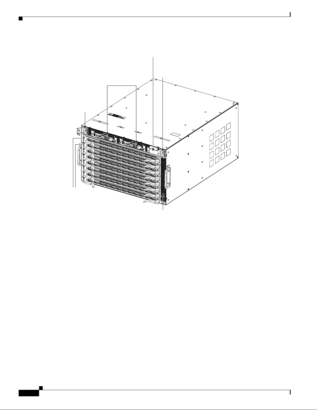
Figure 1 Back of Unit
Power
plug
2
Management I.O
modules
Chassis ID
Power
plug
1
4x copper
line interface
modules
Main air
exhaust
144988
Step 2 Verify that you have a Chassis ID module installed. (See Figure 1).
Step 3 Verify that you have a Fabric Controller installed in the Core slot (see slot 11 in Figure 2). A second
Fabric Controller module (installed in slot 12) is not required for the chassis to function, but is required
to have a non-blocking fabric.
Cisco SFS 7008P InfiniBand Server Switch Installation and Configuration Note
4
78-17434-01 Rev. A0
Page 5
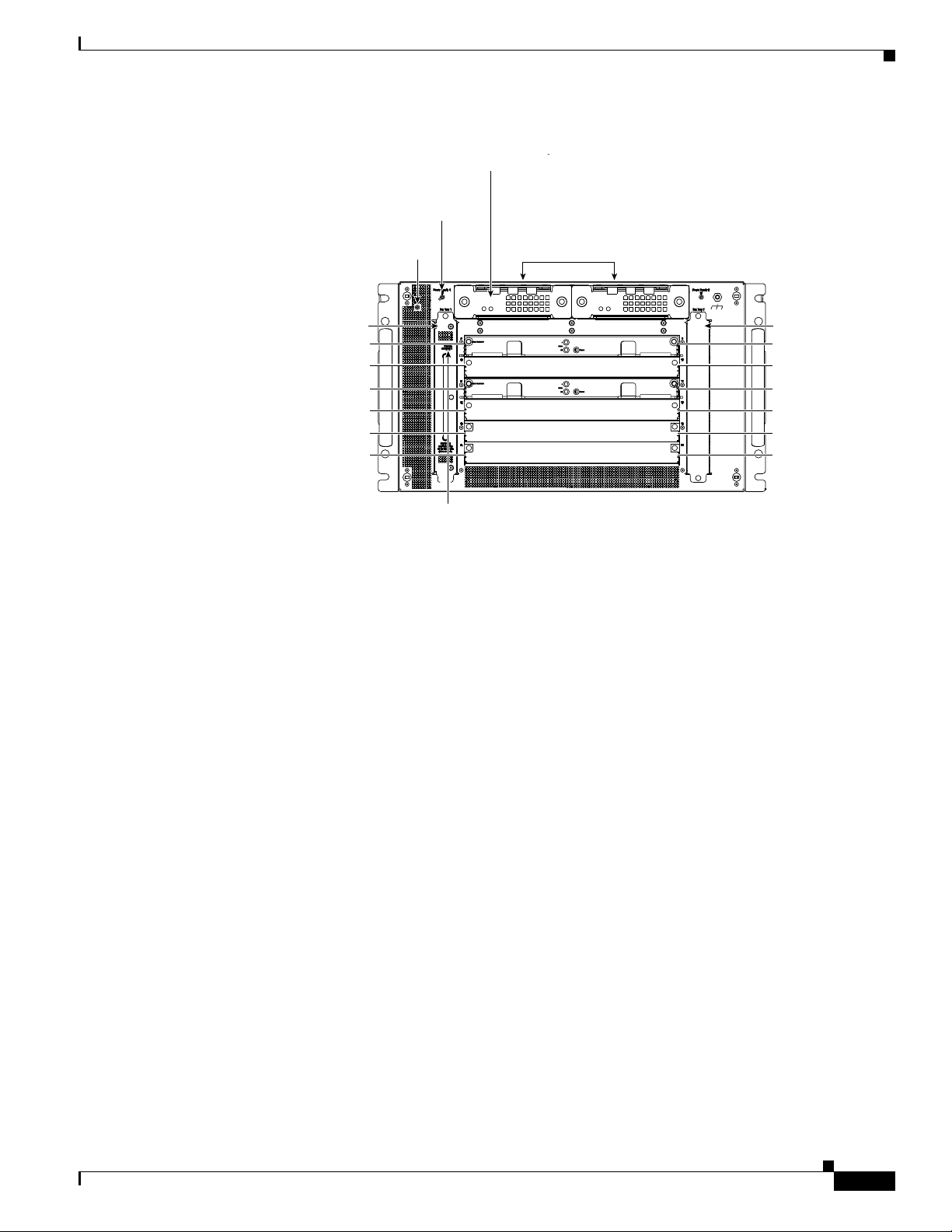
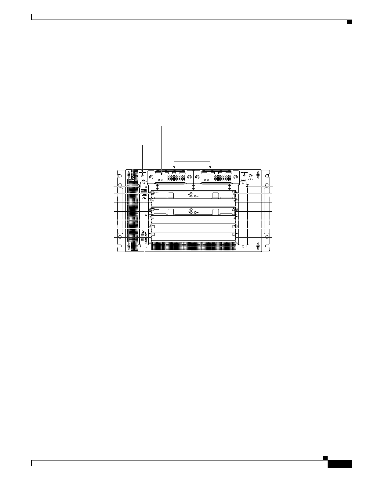
Figure 2 Cisco SFS 7008P Switch Front ViewWithout Bezel
y
Status LED
Power Supply
identity LED
System
Status LED
Power supplies
Fan Fan
Node slot 1 Slot 9
Node slot 2
Core slot 1
Core slot 2
Node slot 3
Node slot 4
Fan tray LED
Verifying Basic Hardware
Slot 10
Slot 11
Slot 12
Slot 13
Slot 14
154497
Step 4 Verify that you have at least one power supply installed. (See Figure 2.)
Step 5 Verify that you have at least one fan module installed. (See Figure 2.)
Step 6 Verify that you have at least one fabric module installed in one of the node slots. The node slots are 9,
10, 13 and 14. (See Figure 2.)
Step 7 Verify that you have two LIMs installed for each fabric module in the node slots. See Figure 3 for an
example of the connections between the LIMs and the fabric modules in the node slots:
78-17434-01 Rev. A0
Cisco SFS 7008P InfiniBand Server Switch Installation and Configuration Note
5
Page 6
Installing the Cisco SFS 7008P Switch into a Rack
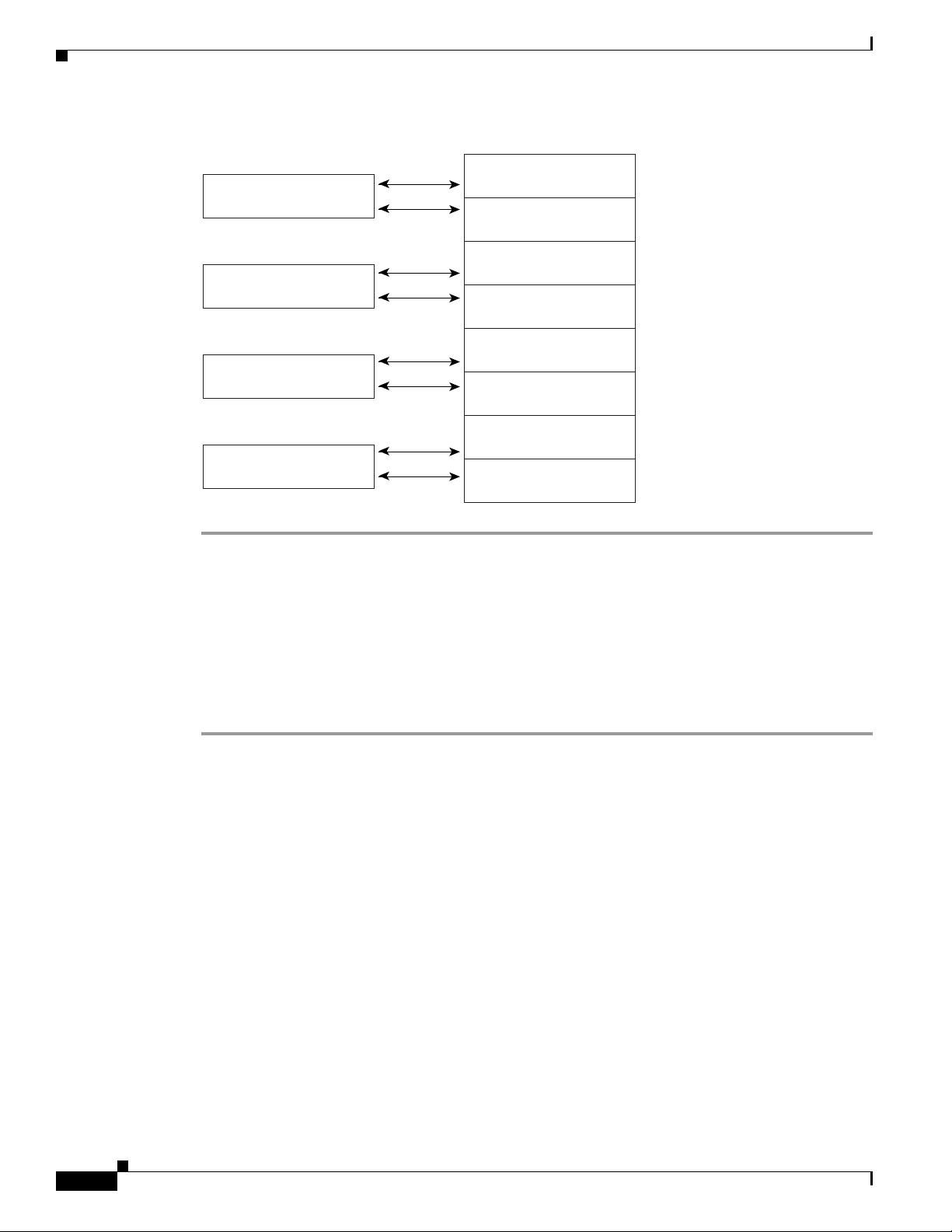
Figure 3 LIM and Fabric Module Connections
Fabric card in slot 9
Fabric card in slot 10
Fabric card in slot 13
LIM card in slot 1
LIM card in slot 2
LIM card in slot 3
LIM card in slot 4
LIM card in slot 5
LIM card in slot 6
LIM card in slot 7
Fabric card in slot 14
LIM card in slot 8
154550
Installing the Cisco SFS 7008P Switch into a Rack
This section describes how to install the Cisco SFS 7008Pswitch in an equipment rack. If you purchased
the custom Cisco SFS 7008P switch shelf, follow the directions in the Cisco SFS 7008 InfiniBand Server
Switch Hardware Installation Guide. To mount the Cisco SFS 7008P switch chassis in an
industry-standard rack, follow these steps:
Step 1 Install a shelf for the chassis as shown in Figure 4, if you have not already done so.
The shelf must support the weight of the chassis, which can be up to 106 pounds if all possible
components are installed.
Cisco SFS 7008P InfiniBand Server Switch Installation and Configuration Note
6
78-17434-01 Rev. A0
Page 7
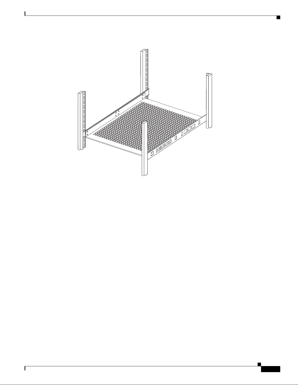
Figure 4 Install Appropriate Shelf
Installing the Cisco SFS 7008P Switch into a Rack
144964
Step 2 Ground yourself using an approved ground wrist-strap.
Step 3 Determine the direction that the switch will be installedand justified in the rack.
The direction that the switch will be justified determines which set of mounting brackets need to be
removed in the next step.
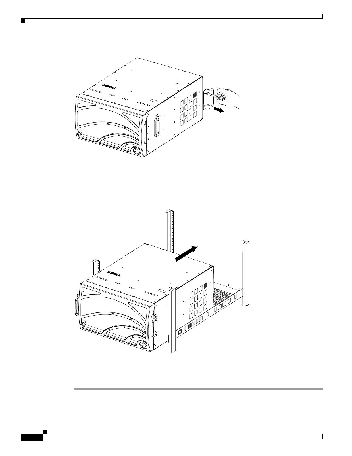
Step 4 Remove one set of mounting brackets, as shown in Figure 5:
• If the switch will be justified towardthe bezel-side in the rack, then unscrew the mounting brackets
from the port-side of the switch.
• If the switch will be justified toward the port-side in the rack, then unscrew the mounting brackets
from the bezel-side of the switch.
78-17434-01 Rev. A0
Cisco SFS 7008P InfiniBand Server Switch Installation and Configuration Note
7
Page 8
Installing the Cisco SFS 7008P Switch into a Rack
Figure 5 Unscrew Extra Mounting Brackets from the Chassis
Step 5 Separate the mounting brackets from the chassis when all screws have been loosened.
Step 6 With 2 or 3 people working together, lift the switch into the rack as shown in Figure 6.
144965
Figure 6 Chassis Set onto Shelf
144966
Step 7 Push the chassis into the rack until the mounting brackets are flush with the rails.
Step 8 Use screws that fit your rack to attach both mounting brackets to the rack posts.
Cisco SFS 7008P InfiniBand Server Switch Installation and Configuration Note
8
78-17434-01 Rev. A0
Page 9
Installing Optional High-Availability Components
If you purchased a High-Availability (HA) package, install the following components:
• Redundant Power Supply; see the power supply locations in Figure 7. Install the second power
supply according to the directions in the Power Supply Module Installation Guide in the package.
Figure 7 Power Supplies and Fans Located in the Front of the Unit with the Bezel Removed
Power Supply
Status LED
Power Supply
identity LED
System
Status LED
Fan Fan
Node slot 1 Slot 9
Node slot 2
Core slot 1
Core slot 2
Node slot 3
Node slot 4
Power supplies
Installing the Cisco SFS 7008P Switch into a Rack
Slot 10
Slot 11
Slot 12
Slot 13
Slot 14
154497
Fan tray LED
• Redundant Fan Tray; see the fan locations in Figure 7. Install the second fan according to the Fan
Module Installation Guide in the package.
• Redundant Management Interface Module; see the location of the Management I/O Modules in
Figure 8. Install the second I/O Module according to the directions in the Management Interface
Module Installation Guide in the package.
78-17434-01 Rev. A0
Cisco SFS 7008P InfiniBand Server Switch Installation and Configuration Note
9
Page 10

Installing the Cisco SFS 7008P Switch into a Rack
Figure 8 Management I/O Modules Located in the Back of the Unit
Management I.O
Power
plug
2
Chassis ID
Power
plug
1
modules
4x copper
line interface
modules
Main air
exhaust
144988
ConfiguringandConnectingHostChannelExpansionCardforIBMBladeCenter
This section briefly describes configuring your InfiniBand host. Download the configuration software
and an integrated suite of drivers including IPoIB, SRP, SDP, uDAPL and MPI from the Cisco Software
Center at this URL:
http://www.cisco.com/public/sw-center
Install the Host Channel Expansion Card for IBM BladeCenter by doing the following:
Step 1 Power down the host system following proper grounding procedures.
Step 2 Unpack the HCA module and insert it into an open 64-bit PCI or PCI-X slot.
Step 3 Power on the host system.
Installing Host Channel Expansion Card Linux Drivers
Make sure your Linux kernel is supported. See www.cisco.com for a list of supported versions.
Cisco SFS 7008P InfiniBand Server Switch Installation and Configuration Note
10
78-17434-01 Rev. A0
Page 11

Installing the Cisco SFS 7008P Switch into a Rack
To install the Host Channel Expansion Card for IBM BladeCenter drivers after you have installed the
HCA Expansion Card, follow these steps:
Step 1 Locate your downloaded software direcory.
Step 2 Open a terminal or graphic window and access the top-level directory.
Step 3 Execute the command ./tsinstall in a terminal window.
# cdmount ./tsinstall
This program automatically detects the available kernel and installs the appropriate drivers as RPM
packages. By default, the files are saved in the /usr/local/cisco directory.
Step 4 Configure the IPoIB driver by assigning an IP address to interface ib0 and/or ib1, which corresponds to
the two HCA ports. IPoIB drivers load when the interfaces are used for the first time. To assign ib
interfaces, enter ifconfig ib# ip address netmask netmask.
This example configures one HCA:
# ifconfig ib0 192.168.0.1 netmask 255.255.255.0
#
# ifconfig ib1 192.168.1.1 netmask 255.255.255.0
#
This example configures two HCAs:
# ifconfig ib0 192.168.0.1 netmask 255.255.255.0
#
# ifconfig ib1 192.168.1.1 netmask 255.255.255.0
#
# ifconfig ib2 192.168.2.1 netmask 255.255.255.0
#
# ifconfig ib3 192.168.3.1 netmask 255.255.255.0
#
Step 5 Merge ib0 and ib1 for port-to-port redundancy, if desired.
Step 6 (Optional) Configure MPI by following these steps:
• Make sure that your connections to the HCA uses port 1 of the first HCA. MPI requires the use of
HCA 1, port 1.
• Set up rsh or ssh on two nodes so that you can run commands between a remote and local node
without entering a login or password. This is required to use the MPI protocol.
• Either add paths to your environment PATH:
/usr/local/cisco/mpi/mpich/bin
/usr/local/cisco/bin
or
Add directories to your PATH variable. For example:
export PATH=$PATH:/usr/local/cisco
Step 7 Configure all other drivers, including SDP.
78-17434-01 Rev. A0
Cisco SFS 7008P InfiniBand Server Switch Installation and Configuration Note
11
Page 12
Installing the Cisco SFS 7008P Switch into a Rack
Installing Non-WHQL Host Channel Expansion Card Drivers on a Windows 2000 Server (BoIB and non-BoIB)
The SFS 7008 chassis has Topspin operating system version 2.5.0 preloaded. DRIVERS TOO? OR
DOWNLOAD?? IN STEP 4, THE SDK COMES UP - WHERE DID THAT COME FROM?
To install Windows drivers after you have installed the HCA Expansion Card, follow these steps:
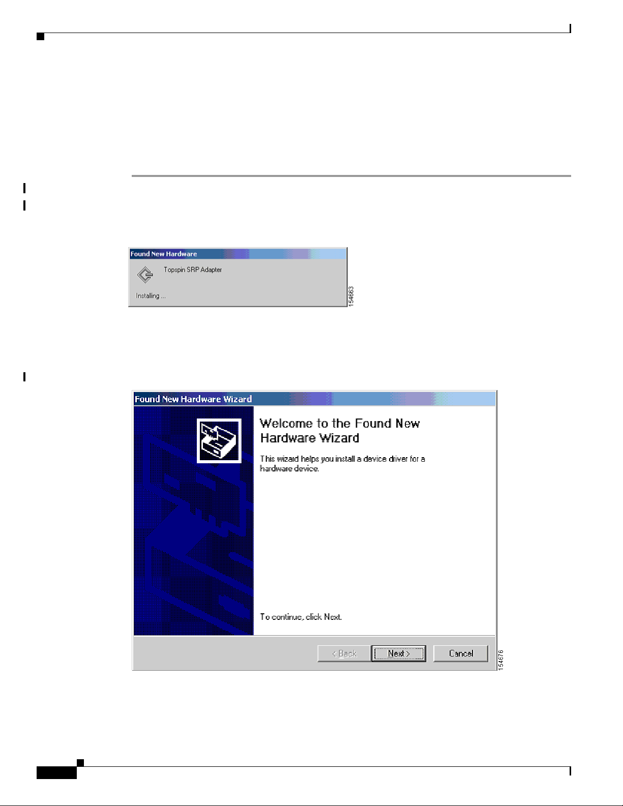
Step 1 Log on to your Windows 2000 host.
A Found New Hardware alert appears (see Figure 9).
Figure 9 Found New Hardware Alert
Step 2 Ignore the alert.
The Found New Hardware Wizard window opens (see Figure 10).
Figure 10 Found New Hardware Wizard WIZARD.TIF
12
Step 3 Click Cancel.
Cisco SFS 7008P InfiniBand Server Switch Installation and Configuration Note
78-17434-01 Rev. A0
Page 13

Note This wizard may not appear immediately. When the wizard does appear, click Cancel.
Step 4 Run Topspin-ib-W2k-releaseNumber.exe.
The InfiniBand SDK Setup window opens (see Figure 11).
Figure 11 InfiniBand SDK Setup Window
Installing the Cisco SFS 7008P Switch into a Rack
Step 5 Click Next.
Step 6 Click the I Agree to the terms listed above radio button, and then click Next.
Step 7 Click Next.
Step 8 Click Next.
Step 9 Click Finish.
Step 10 Click Yes.
78-17434-01 Rev. A0
The End User License Agreement window opens.
The Product Information window appears.
The Ready to Install window opens.
The installation executes. The Installation Complete window appears when the installation completes.
The system prompts you to reboot. If you have not previously installed host drivers on this system, you
do not need to reboot.
Your host reboots.
Cisco SFS 7008P InfiniBand Server Switch Installation and Configuration Note
13
Page 14

Installing the Cisco SFS 7008P Switch into a Rack
Installing Host Channel Expansion Card Windows 2003 Drivers
If you have not already done so, download an integrated suite of HCA drivers including IPoIB, SRP,
SDP, uDAPL and MPI from the Cisco Software Center at this URL:
http://www.cisco.com/public/sw-center
To install the Windows 2003 drivers, follow these steps:
Step 1 Log on to your Windows 2003 host.
Step 2 HOW DID SW GET ON MY COMPUTER?HOW DO I START THIS????????????.
The Product Install window appears (see Figure 12).
Figure 12 Product Install Window
14
Step 3 Click Next.
The End User License Agreement appears.
Step 4 Click the I Agree to the terms listed above radio button, and then click Next to continue.
The Product Information window appears.
Step 5 Click Next.
The Installation in Progress window appears with the status of the installation (see Figure 13).
Cisco SFS 7008P InfiniBand Server Switch Installation and Configuration Note
78-17434-01 Rev. A0
Page 15

Installing the Cisco SFS 7008P Switch into a Rack
Figure 13 Installation Status
A Windows driver dialog box appears. This dialog box explains that the new drivers do not contain a
Windows signature. Although the drivers are not digitally signed, they are tested using the Microsoft
HCT suite. WHQL submission materials are available per request (CAB files, etc.).
Step 6 Click Continue Anyway (Figure 14) each time the Windows Logo testing dialog box appears.
Figure 14 Testing Dialog Box
The driver installation notice shown in Figure 15 appears for each host channel adapter you have
installed.
Step 7 Click Yes in the Driver Installation Notice dialog window. (See Figure 15.)
78-17434-01 Rev. A0
Cisco SFS 7008P InfiniBand Server Switch Installation and Configuration Note
15
Page 16

Installing the Cisco SFS 7008P Switch into a Rack
Figure 15 Driver Installation Notice
Step 8 Important: Ignore the Found New Hardware Wizard (see Figure 16) when it appears because it will
continue without user intervention. This window appears three times (twice for the IPoIB and once for
SRP).
Figure 16 Ignore the Found New Hardware Wizard Windows
Step 9 Click Finish.
Step 10 Reboot the server.
a. In Windows, click Start > Shutdown.
You see the screen in Figure 17.
b. Select Restart from the drop-down menu(see Figure 17).
c. Optionally, enter a reason for the system reboot in the Commentfield(see Figure 17), if your server
requires it.
d. Click OK.
The system reboots and new driver installation is complete.
16
Cisco SFS 7008P InfiniBand Server Switch Installation and Configuration Note
78-17434-01 Rev. A0
Page 17

Figure 17 Restarting Windows Server
Installing the Cisco SFS 7008P Switch into a Rack
Installing WHQL Drivers on a Windows 2000 or 2003 Server (BoIB and non-BoIB)
WHQL drivers are packaged in a .ZIP file. To install WHQL drivers, see the documentation at
http://www.cisco.com. THERE IS NOTHING HERE??!!
Launching the SFS Chassis Manager (Optional)
SFS Chassis Manager is a web-based GUI that can be used to manage a single InfiniBand chassis from
a Web browser. SFS Chassis Manager supports the following browsers:
• Microsoft Internet Explorer version 6
• Netscape Navigator version 6
• Mozilla version 1.4
To launch SFS Chassis Manager, follow these steps:
Step 1 Type the Management IP address of your switch in the address field of your browser and press Enter.
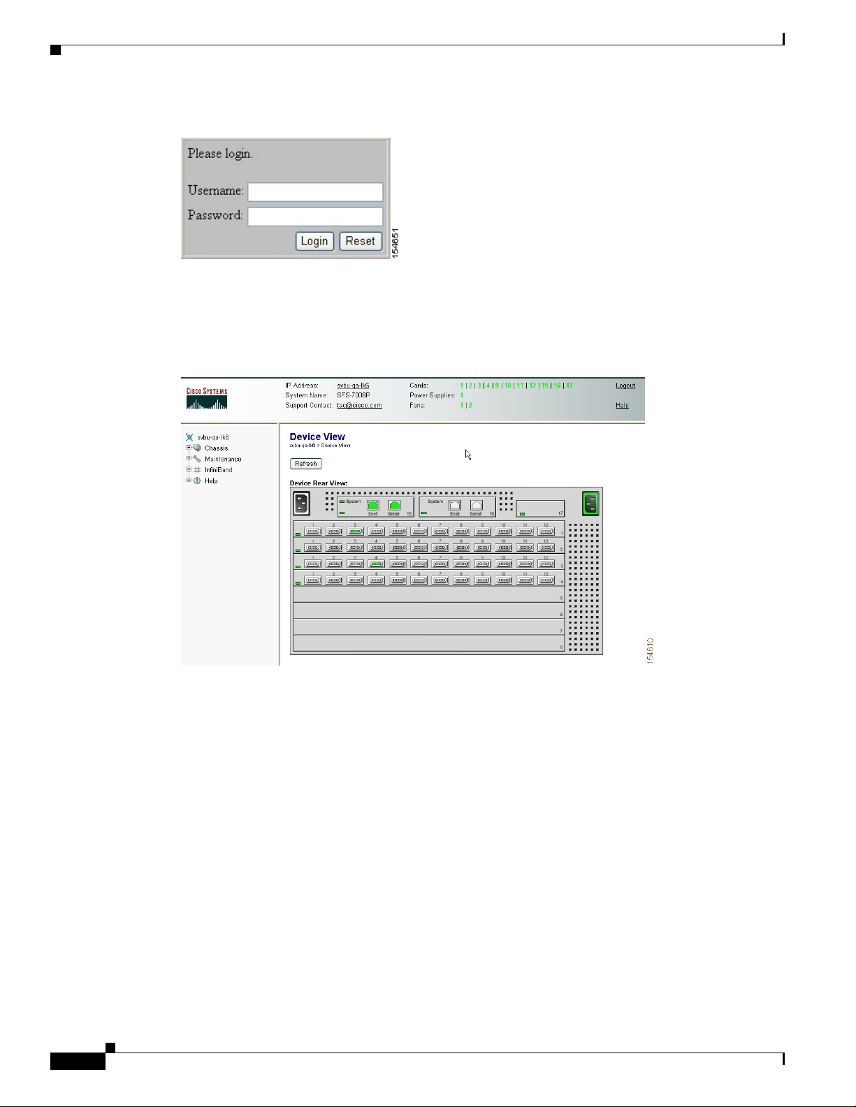
A login window opens. (See Figure 18.)
78-17434-01 Rev. A0
Cisco SFS 7008P InfiniBand Server Switch Installation and Configuration Note
17
Page 18
Installing the Cisco SFS 7008P Switch into a Rack
Figure 18 SFS Chassis Manager Log-In Window
Step 2 Enter your username and password in the log-in window and click Login .
SFS Chassis Manager loads in your browser window as shown in Figures 19 and 20.
Figure 19 SFS Chassis Manager Opening (Rear View)
18
Cisco SFS 7008P InfiniBand Server Switch Installation and Configuration Note
78-17434-01 Rev. A0
Page 19
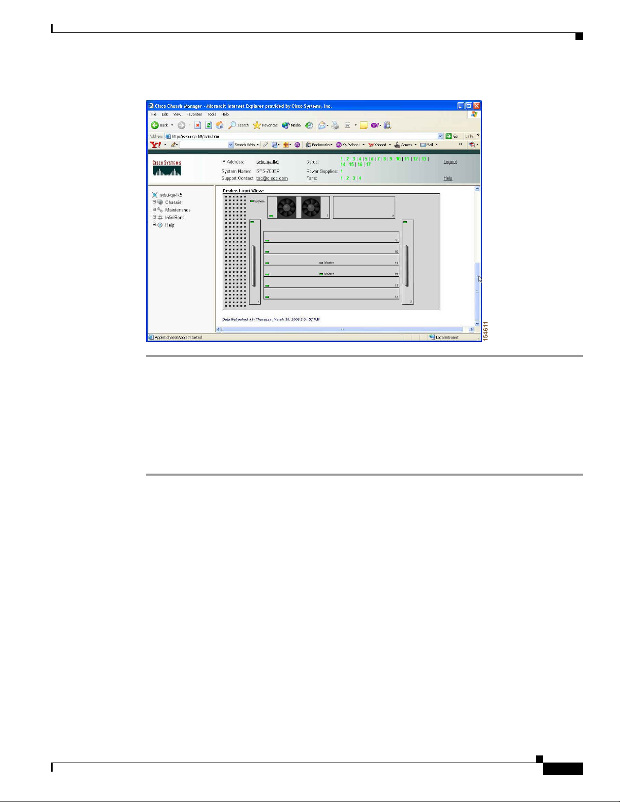
Installing the Cisco SFS 7008P Switch into a Rack
Figure 20 SFS Chassis Manager Opening (Front View)
Installing the SFS Element Manager GUI (Optional)
For more information regarding the SFS Element Manager, see the Cisco SFS 7000 Series Product
Family Element Manager User Guide.
To install Element Manager, follow these steps:
Step 1 Ensure that you have sufficient system resources. You need the following:
• 32 MB free RAM
• 50 MB disk space and 50MB additional temporary space during installation
• 300 MHz processor
• 800 x 600 screen resolution, 16-bit color depth
Step 2 Download the Element Manager software. To download the latest software, access the Cisco Software
Center at this URL:
http://www.cisco.com/public/sw-center
Step 3 Locate the appropriate install file.
• Linux/install_linux_ia64.bin
• Linux/install_linux_x86.bin
• Windows/install_x86.exe
• Solaris/install_solaris_sparc.bin
78-17434-01 Rev. A0
Cisco SFS 7008P InfiniBand Server Switch Installation and Configuration Note
19
Page 20

Troubleshooting
Step 4 Run the installation wizard:
a. On Windows, double-click install.exe.
On Solaris and Linux systems, enter sh ./install_yourOS.bin.
b. Follow the onscreen instructions. Enter location and preference information as requested by the
installation program.
Step 5 Start the SFS Element Manager by following these steps:
a. On Windows platforms, click Programs -> Cisco SFS Element Manager -> Cisco SFS EM
On Linux platforms, change to the installation directory and run SFS Element Manager with
./CiscoEM.
b. When prompted to enter a device name, enter the DNS host name or IP address of the Cisco SFS
7008P switch, and community string for the unrestricted user. The default community string for the
unrestricted user is secret.
Troubleshooting
For all customers, partners, resellers, and distributors who hold valid Cisco service contracts, Cisco
Technical Support provides 24-hour-a-day, award-winning technical assistance. The Cisco Technical
Support Website on Cisco.com features extensive online support resources. In addition, Cisco Technical
Assistance Center (TAC) engineers provide telephone support. If you do not hold a valid Cisco service
contract, contact your reseller.
Cisco Technical Support Website
The Cisco Technical Support Website provides online documents and tools for troubleshooting and
resolving technical issues with Cisco products and technologies. The website is available 24 hours aday,
365 days a year, at this URL:
http://www.cisco.com/techsupport
Access to all tools on the Cisco Technical Support Website requires a Cisco.com user ID and password.
If you have a valid service contract but do not have a user ID or password, you can register at this URL:
http://tools.cisco.com/RPF/register/register.do
Note Use the Cisco Product Identification (CPI) tool to locate your product serial number before submitting
a web or phone request for service. You can access the CPI tool from the Cisco Technical Support
Website by clicking the Tools& Resources link under Documentation & Tools. Choose Cisco Product
Identification Tool from the Alphabetical Index drop-down list, or click the Cisco Product
IdentificationToollink under Alerts & RMAs. The CPI tool offers three search options: by product ID
or model name; by tree view; or for certain products, by copying and pasting show command output.
Search results show an illustration of your product with the serial number label location highlighted.
Locate the serial number label on your product and record the information before placing a service call.
20
Cisco SFS 7008P InfiniBand Server Switch Installation and Configuration Note
78-17434-01 Rev. A0
Page 21

Submitting a Service Request
Using the online TAC Service Request Tool is the fastest way to open S3 and S4 service requests. (S3
and S4 service requests are those in which your network is minimally impaired or for which you require
product information.) After you describe your situation, the TAC Service Request Tool provides
recommended solutions. If your issue is not resolved using the recommended resources, your service
request is assigned to a Cisco TAC engineer. The TAC Service Request Tool is located at
http://www.cisco.com/techsupport/servicerequest.
For S1 or S2 service requests or if you do not have Internet access, contact the Cisco TAC by telephone.
(S1 or S2 service requests are those in which your production network is down or severely degraded.)
Cisco TAC engineers are assigned immediately to S1 and S2 service requests to help keep your business
operations running smoothly.
To open a service request by telephone, use one of the following numbers:
Asia-Pacific: +61 2 8446 7411 (Australia: 1 800 805 227)
EMEA: +32 2 704 55 55
USA: 1 800 553-2447
For a complete list of Cisco TAC contacts, see http://www.cisco.com/techsupport/contacts.
Translated Safety Warnings
Definitions of Service Request Severity
To ensure that all service requests are reported in a standard format, Cisco has established severity
definitions.
Severity 1 (S1)—Your network is “down,” or there is a critical impact to your business operations. You
and Cisco will commit all necessary resources around the clock to resolve the situation.
Severity 2 (S2)—Operation of an existing network is severely degraded, or significant aspects of your
business operation are negatively affected by inadequate performance of Cisco products. You and Cisco
will commit full-time resources during normal business hours to resolve the situation.
Severity 3 (S3)—Operational performance of your network is impaired, but most business operations
remain functional. You and Cisco will commit resources during normal business hours to restore service
to satisfactory levels.
Severity 4 (S4)—You require information or assistance with Cisco product capabilities, installation, or
configuration. There is little or no effect on your business operations.
Translated Safety Warnings
Safety warnings appear throughout this publication in procedures that may harm you if performed
incorrectly. A warning symbol precedes each warning statement.
78-17434-01 Rev. A0
Cisco SFS 7008P InfiniBand Server Switch Installation and Configuration Note
21
Page 22

Translated Safety Warnings
Warning
Waarschuwing
Varoitus
IMPORTANT SAFETY INSTRUCTIONS
This warning symbol means danger.You are in a situation that could cause bodily injury. Before you
work on any equipment, be aware of the hazards involved with electrical circuitry and be familiar
with standard practices for preventing accidents. Use the statement number provided at the end of
each warning to locate its translation in the translated safety warnings that accompanied this
device. Statement 1071
SAVE THESE INSTRUCTIONS
BELANGRIJKE VEILIGHEIDSINSTRUCTIES
Dit waarschuwingssymbool betekent gevaar. U verkeert in een situatie die lichamelijk letsel kan
veroorzaken. Voordat u aan enige apparatuur gaat werken, dient u zich bewust te zijn van de bij
elektrische schakelingen betrokken risico's en dient u op de hoogte te zijn van de standaard
praktijken om ongelukken te voorkomen. Gebruik het nummer van de verklaring onderaan de
waarschuwing als u een vertaling van de waarschuwing die bij het apparaat wordt geleverd, wilt
raadplegen.
BEWAAR DEZE INSTRUCTIES
TÄRKEITÄ TURVALLISUUSOHJEITA
Tämä varoitusmerkki merkitsee vaaraa. Tilanne voi aiheuttaa ruumiillisia vammoja. Ennen kuin
käsittelet laitteistoa, huomioi sähköpiirien käsittelemiseen liittyvät riskit ja tutustu
onnettomuuksien yleisiin ehkäisytapoihin. Turvallisuusvaroitusten käännökset löytyvät laitteen
mukana toimitettujen käännettyjen turvallisuusvaroitusten joukosta varoitusten lopussa näkyvien
lausuntonumeroiden avulla.
Attention
Warnung
SÄILYTÄ NÄMÄ OHJEET
IMPORTANTES INFORMATIONS DE SÉCURITÉ
Ce symbole d'avertissement indique un danger. Vous vous trouvez dans une situation pouvant
entraîner des blessures ou des dommages corporels. Avant de travailler sur un équipement, soyez
conscient des dangers liés aux circuits électriques et familiarisez-vous avec les procédures
couramment utilisées pour éviter les accidents. Pour prendre connaissance des traductions des
avertissements figurant dans les consignes de sécurité traduites qui accompagnent cet appareil,
référez-vous au numéro de l'instruction situé à la fin de chaque avertissement.
CONSERVEZ CES INFORMATIONS
WICHTIGE SICHERHEITSHINWEISE
DiesesWarnsymbolbedeutet Gefahr.Siebefindensichin einer Situation, diezuVerletzungenführen
kann. Machen Sie sich vor der Arbeit mit Geräten mit den Gefahren elektrischer Schaltungen und
den üblichen Verfahren zur Vorbeugung vor Unfällen vertraut. Suchen Sie mit der am Ende jeder
Warnung angegebenen Anweisungsnummer nach der jeweiligen Übersetzung in den übersetzten
Sicherheitshinweisen, die zusammen mit diesem Gerät ausgeliefert wurden.
BEWAHREN SIE DIESE HINWEISE GUT AUF.
22
Cisco SFS 7008P InfiniBand Server Switch Installation and Configuration Note
78-17434-01 Rev. A0
Page 23

Translated Safety Warnings
Avvertenza
Advarsel
Aviso
IMPORTANTI ISTRUZIONI SULLA SICUREZZA
Questo simbolo di avvertenza indica un pericolo. La situazione potrebbe causare infortuni alle
persone. Prima di intervenire su qualsiasi apparecchiatura, occorre essere al corrente dei pericoli
relativi ai circuiti elettrici e conoscere le procedure standard per la prevenzione di incidenti.
Utilizzare il numero di istruzione presente alla fine di ciascuna avvertenza per individuare le
traduzioni delle avvertenze riportate in questo documento.
CONSERVARE QUESTE ISTRUZIONI
VIKTIGE SIKKERHETSINSTRUKSJONER
Dette advarselssymbolet betyr fare. Du er i en situasjon som kan føre til skade på person. Før du
begynner å arbeide med noe av utstyret, må du være oppmerksom på farene forbundet med
elektriske kretser, og kjennetil standardprosedyrerfor åforhindre ulykker. Bruk nummeret i slutten
avhver advarsel forå finne oversettelsen ide oversatte sikkerhetsadvarslenesom fulgte meddenne
enheten.
TA VARE PÅ DISSE INSTRUKSJONENE
INSTRUÇÕES IMPORTANTES DE SEGURANÇA
Este símbolo de aviso significa perigo. Você está em uma situação que poderá ser causadora de
lesões corporais. Antes de iniciar a utilização de qualquer equipamento, tenha conhecimento dos
perigos envolvidos nomanuseio de circuitoselétricos e familiarize-se com aspráticas habituais de
prevenção de acidentes. Utilize o número da instrução fornecido ao final de cada aviso para
localizar sua tradução nos avisos de segurança traduzidos que acompanham este dispositivo.
¡Advertencia!
Varning!
GUARDE ESTAS INSTRUÇÕES
INSTRUCCIONES IMPORTANTES DE SEGURIDAD
Este símbolo de aviso indica peligro. Existe riesgo para su integridad física. Antes de manipular
cualquier equipo, considere los riesgos de la corriente eléctrica y familiarícese con los
procedimientos estándar de prevención de accidentes. Al final de cada advertencia encontrará el
número que leayudará a encontrarel texto traducido en elapartado de traduccionesque acompaña
a este dispositivo.
GUARDE ESTAS INSTRUCCIONES
VIKTIGA SÄKERHETSANVISNINGAR
Denna varningssignal signalerar fara. Du befinner dig i en situation som kan leda till personskada.
Innan du utför arbete på någon utrustning måste du vara medveten om farorna med elkretsar och
känna till vanliga förfaranden för att förebygga olyckor. Använd det nummer som finns i slutet av
varje varning för att hitta dess översättning i de översatta säkerhetsvarningar som medföljer denna
anordning.
SPARA DESSA ANVISNINGAR
78-17434-01 Rev. A0
Cisco SFS 7008P InfiniBand Server Switch Installation and Configuration Note
23
Page 24

Translated Safety Warnings
24
Cisco SFS 7008P InfiniBand Server Switch Installation and Configuration Note
78-17434-01 Rev. A0
Page 25

Translated Safety Warnings
Aviso
Advarsel
INSTRUÇÕES IMPORTANTES DE SEGURANÇA
Estesímbolo de avisosignificaperigo. Você se encontraem uma situaçãoem que hárisco de lesões
corporais. Antes de trabalhar com qualquerequipamento, esteja ciente dos riscos que envolvem os
circuitos elétricos e familiarize-se com as práticas padrão de prevenção de acidentes. Use o
número da declaração fornecido ao final de cada aviso para localizar sua tradução nos avisos de
segurança traduzidos que acompanham o dispositivo.
GUARDE ESTAS INSTRUÇÕES
VIGTIGE SIKKERHEDSANVISNINGER
Dette advarselssymbol betyder fare. Du befinder dig i en situation med risiko for
legemesbeskadigelse. Før du begynder arbejde på udstyr, skal du være opmærksom på de
involverede risici, der er ved elektriske kredsløb, og du skal sætte dig ind i standardprocedurer til
undgåelse af ulykker. Brug erklæringsnummeret efter hver advarsel for at finde oversættelsen i de
oversatte advarsler, der fulgte med denne enhed.
GEM DISSE ANVISNINGER
78-17434-01 Rev. A0
Cisco SFS 7008P InfiniBand Server Switch Installation and Configuration Note
25
Page 26

Translated Safety Warnings
26
Cisco SFS 7008P InfiniBand Server Switch Installation and Configuration Note
78-17434-01 Rev. A0
Page 27

Obtaining Documentation
Cisco documentation and additional literature are available on Cisco.com. Cisco also provides several
ways to obtain technical assistance and other technical resources. These sections explain how to obtain
technical information from Cisco Systems.
Cisco.com
You can access the most current Cisco documentation at this URL:
http://www.cisco.com/techsupport
You can access the Cisco website at this URL:
http://www.cisco.com
You can access international Cisco websites at this URL:
http://www.cisco.com/public/countries_languages.shtml
Product Documentation DVD
Obtaining Documentation
The Product Documentation DVD is a comprehensive library of technical product documentation on a
portable medium. The DVD enables you to access multiple versions of installation, configuration, and
command guides for Cisco hardware and software products. With the DVD, you have access to the same
HTML documentation that is found on the Cisco website without being connected to the Internet.
Certain products also have .PDF versions of the documentation available.
The Product Documentation DVD is availableas asingle unit or as a subscription. Registered Cisco.com
users (Cisco direct customers) can order a Product Documentation DVD (product number
DOC-DOCDVD= or DOC-DOCDVD=SUB) from Cisco Marketplace at this URL:
http://www.cisco.com/go/marketplace/
Ordering Documentation
Registered Cisco.com users may order Cisco documentation at the Product Documentation Store in the
Cisco Marketplace at this URL:
http://www.cisco.com/go/marketplace/
Nonregistered Cisco.com users can order technical documentation from 8:00 a.m. to 5:00 p.m.
(0800 to 1700) PDT by calling 1 866 463-3487 in the United States and Canada, or elsewhere by
calling 011 408 519-5055. You can also order documentation by e-mail at
tech-doc-store-mkpl@external.cisco.com or by fax at 1 408 519-5001 in the United States and Canada,
or elsewhere at 011 408 519-5001.
Documentation Feedback
You can rate and provide feedback about Cisco technical documents by completing the online feedback
form that appears with the technical documents on cisco.com.
78-17434-01 Rev. A0
Cisco SFS 7008P InfiniBand Server Switch Installation and Configuration Note
27
Page 28

Cisco Product Security Overview
You can submit comments about Cisco documentation by using the response card (if present) behind the
front cover of your document or by writing to the following address:
Cisco Systems
Attn: Customer Document Ordering
170 West Tasman Drive
San Jose, CA 95134-9883
We appreciate your comments.
Cisco Product Security Overview
Cisco provides a free online Security Vulnerability Policy portal at this URL:
http://www.cisco.com/en/US/products/products_security_vulnerability_policy.html
From this site, you will find information about how to:
• Report security vulnerabilities in Cisco products.
• Obtain assistance with security incidents that involve Cisco products.
• Register to receive security information from Cisco.
A current list of security advisories, security notices, and security responses for Cisco products is
available at this URL:
http://www.cisco.com/go/psirt
To see security advisories, security notices, and security responses as they are updated in real time, you
can subscribe to the Product Security Incident Response Team Really Simple Syndication (PSIRT RSS)
feed. Information about how to subscribe to the PSIRT RSS feed is found at this URL:
http://www.cisco.com/en/US/products/products_psirt_rss_feed.html
Reporting Security Problems in Cisco Products
Cisco is committedto delivering secure products. Wetestour products internally before werelease them,
and we strive to correct all vulnerabilities quickly. If you think that you have identified a vulnerability
in a Cisco product, contact PSIRT:
• For Emergencies only —security-alert@cisco.com
An emergencyis either a condition in which a system is under active attack or a condition for which
a severe and urgent security vulnerability should be reported. All other conditions are considered
nonemergencies.
• For Nonemergencies —psirt@cisco.com
In an emergency, you can also reach PSIRT by telephone:
• 1 877 228-7302
• 1 408 525-6532
Tip We encourage you to use Pretty Good Privacy (PGP) or a compatible product (for example, GnuPG) to
encrypt any sensitiveinformationthat yousend to Cisco. PSIRT can workwith information that has been
encrypted with PGP versions 2.x through 9.x.
Cisco SFS 7008P InfiniBand Server Switch Installation and Configuration Note
28
78-17434-01 Rev. A0
Page 29

Never use a revoked or an expired encryption key. The correct public key to use in your correspondence
with PSIRT is the one linked in the Contact Summary section of the Security Vulnerability Policy page
at this URL:
http://www.cisco.com/en/US/products/products_security_vulnerability_policy.html
The link on this page has the current PGP key ID in use.
If you do not have or use PGP, contact PSIRT at the aforementioned e-mail addresses or phone numbers
before sending any sensitive material to find other means of encrypting the data.
Obtaining Technical Assistance
Cisco Technical Support provides 24-hour-a-day award-winning technical assistance. The Cisco
Technical Support & Documentation website on Cisco.com features extensive online support resources.
In addition, if you have a valid Cisco service contract, Cisco Technical Assistance Center (TAC)
engineers provide telephone support. If you do not have a valid Cisco service contract, contact your
reseller.
Obtaining Technical Assistance
Cisco Technical Support & Documentation Website
The Cisco Technical Support & Documentation website provides online documents and tools for
troubleshooting and resolving technical issues with Cisco products and technologies. The website is
available 24 hours a day, at this URL:
http://www.cisco.com/techsupport
Access to all tools on the Cisco TechnicalSupport & Documentation website requires a Cisco.com user
ID and password. If you have a valid service contract but do not have a user ID or password, you can
register at this URL:
http://tools.cisco.com/RPF/register/register.do
Note Use the Cisco Product Identification (CPI) tool to locate your product serial number before submitting
a web or phone request for service. You can access the CPI tool from the Cisco Technical Support &
Documentation website by clicking the Tools & Resources link under Documentation & Tools. Choose
Cisco Product Identification Tool from the Alphabetical Index drop-down list, or click the Cisco
Product Identification Tool link under Alerts & RMAs. The CPI tool offers three search options: by
product ID or model name; by tree view; or for certain products, by copying and pasting showcommand
output. Search results show an illustration of your product with the serial number label location
highlighted. Locate the serial number label on your product and record the information before placing a
service call.
78-17434-01 Rev. A0
Cisco SFS 7008P InfiniBand Server Switch Installation and Configuration Note
29
Page 30

Obtaining Technical Assistance
Submitting a Service Request
Using the online TAC Service Request Tool is the fastest way to open S3 and S4 service requests. (S3
and S4 service requests are those in which your network is minimally impaired or for which you require
product information.) After you describe your situation, the TAC Service Request Tool provides
recommended solutions. If your issue is not resolved using the recommended resources, your service
request is assigned to a Cisco engineer. The TAC Service Request Tool is located at this URL:
http://www.cisco.com/techsupport/servicerequest
For S1 or S2 service requests, or if you do not have Internet access, contact the Cisco TAC by telephone.
(S1 or S2 service requests are those in which your production network is down or severely degraded.)
Cisco engineers are assigned immediately to S1 and S2 service requests to help keep your business
operations running smoothly.
To open a service request by telephone, use one of the following numbers:
Asia-Pacific: +61 2 8446 7411 (Australia: 1 800 805 227)
EMEA: +32 2 704 55 55
USA: 1 800 553-2447
For a complete list of Cisco TAC contacts, go to this URL:
http://www.cisco.com/techsupport/contacts
30
Cisco SFS 7008P InfiniBand Server Switch Installation and Configuration Note
78-17434-01 Rev. A0
Page 31

Obtaining Additional Publications and Information
Definitions of Service Request Severity
To ensure that all service requests are reported in a standard format, Cisco has established severity
definitions.
Severity 1 (S1)—An existing network is down, or there is a critical impact to your business operations.
You and Cisco will commit all necessary resources around the clock to resolve the situation.
Severity 2 (S2)—Operation of an existing network is severely degraded, or significant aspects of your
business operations arenegativelyaffected by inadequate performance of Cisco products. You and Cisco
will commit full-time resources during normal business hours to resolve the situation.
Severity 3 (S3)—Operational performance of the network is impaired, while most business operations
remain functional. You and Cisco will commit resources during normal business hours to restore service
to satisfactory levels.
Severity 4 (S4)—You require information or assistance with Cisco product capabilities, installation, or
configuration. There is little or no effect on your business operations.
Obtaining Additional Publications and Information
Information about Cisco products, technologies, and network solutions is available from various online
and printed sources.
• The Cisco Product Quick Reference Guide is a handy, compact reference tool that includes brief
product overviews, key features, sample part numbers, and abbreviated technical specifications for
many Cisco products that are sold through channel partners. It is updated twice a year and includes
the latest Cisco offerings. To order and find out more about the Cisco Product Quick Reference
Guide, go to this URL:
http://www.cisco.com/go/guide
• Cisco Marketplace provides a variety of Cisco books, reference guides, documentation, and logo
merchandise. Visit Cisco Marketplace, the company store, at this URL:
http://www.cisco.com/go/marketplace/
• Cisco Press publishesa wide range of general networking, training and certification titles. Both new
and experienced users will benefit from these publications. For current Cisco Press titles and other
information, go to Cisco Press at this URL:
http://www.ciscopress.com
• Packet magazine is the Cisco Systems technical user magazine for maximizing Internet and
networking investments. Each quarter, Packet delivers coverage of the latest industry trends,
technology breakthroughs, and Cisco products and solutions, as well as network deployment and
troubleshooting tips, configuration examples, customer case studies, certification and training
information, and links to scores of in-depth online resources. You can access Packet magazine at
this URL:
http://www.cisco.com/packet
• iQ Magazine is the quarterly publication from Cisco Systems designed to help growing companies
learn how they can use technology to increase revenue, streamline their business, and expand
services. The publication identifies the challenges facing these companies and the technologies to
help solve them, using real-world case studies and business strategies to help readers make sound
technology investment decisions. You can access iQ Magazine at this URL:
http://www.cisco.com/go/iqmagazine
78-17434-01 Rev. A0
Cisco SFS 7008P InfiniBand Server Switch Installation and Configuration Note
31
Page 32

Obtaining Additional Publications and Information
or view the digital edition at this URL:
http://ciscoiq.texterity.com/ciscoiq/sample/
• Internet Protocol Journal is a quarterly journal published by Cisco Systems for engineering
professionals involved in designing, developing, and operating public and private internets and
intranets. You can access the Internet Protocol Journal at this URL:
http://www.cisco.com/ipj
• Networking products offered by Cisco Systems, as well as customer support services, can be
obtained at this URL:
http://www.cisco.com/en/US/products/index.html
• Networking Professionals Connection is an interactive website for networking professionals to
share questions, suggestions, and information about networking products and technologies with
Cisco experts and other networking professionals. Join a discussion at this URL:
http://www.cisco.com/discuss/networking
• World-class networking training is available from Cisco. You can view current offerings at
this URL:
http://www.cisco.com/en/US/learning/index.html
32
Cisco SFS 7008P InfiniBand Server Switch Installation and Configuration Note
78-17434-01 Rev. A0
Page 33

Obtaining Additional Publications and Information
78-17434-01 Rev. A0
Cisco SFS 7008P InfiniBand Server Switch Installation and Configuration Note
33
Page 34

Obtaining Additional Publications and Information
This document is to be used in conjunction with the Cisco SFS 7000P Installation and Configuration Note.
CCSP, CCVP, the Cisco Square Bridge logo, Follow Me Browsing, and StackWise are trademarks of Cisco Systems, Inc.; Changing the Way We
Work, Live, Play, and Learn, and iQuick Study are service marks of Cisco Systems, Inc.; and Access Registrar, Aironet, BPX, Catalyst, CCDA,
CCDP, CCIE, CCIP, CCNA, CCNP, Cisco, the Cisco Certified Internetwork Expert logo, Cisco IOS, Cisco Press, Cisco Systems, Cisco Systems
Capital, the Cisco Systems logo, Cisco Unity, Enterprise/Solver, EtherChannel, EtherFast, EtherSwitch, Fast Step, FormShare, GigaDrive,
GigaStack, HomeLink, Internet Quotient, IOS, IP/TV, iQ Expertise, the iQ logo, iQ Net Readiness Scorecard, LightStream, Linksys, MeetingPlace,
MGX, the Networkers logo, Networking Academy, Network Registrar, Packet, PIX, Post-Routing, Pre-Routing, ProConnect, RateMUX,
ScriptShare, SlideCast, SMARTnet, The Fastest Way to Increase Your Internet Quotient, and TransPath are registered trademarks of Cisco Systems,
Inc. and/or its affiliates in the United States and certain other countries.
All other trademarks mentioned in this document or Website are the property of their respective owners. The use of the word partner does not imply
a partnership relationship between Cisco and any other company. (0601R)
© 2006 Cisco Systems, Inc. All rights reserved.
34
Cisco SFS 7008P InfiniBand Server Switch Installation and Configuration Note
78-17434-01 Rev. A0
 Loading...