

Page 1

Cisco Global Site Selector 4491
Hardware Installation Guide
December 2004
Corporate Headquarters
Cisco Systems, Inc.
170 West Tasman Drive
San Jose, CA 95134-1706
USA
http://www.cisco.com
Tel: 408 526-4000
800 553-NETS (6387)
Fax: 408 526-4100
Text Part Number: 78-16356-01
Page 2

THE SOFTWARE LICENSE AND LIMITED WARRANTY FOR THE ACCOMPANYING PRODUCT ARE SET FORTH IN THE INFORMATION
PACKET THAT SHIPPED WITH THE PRODUCT AND ARE INCORPORATED HEREIN BY THIS REFERENCE. IF YOU ARE UNABLE TO
LOCATE THE SOFTWARE LICENSE OR LIMITED WARRANTY, CONTACT YOUR CISCO REPRESENTATIVE FOR A COPY.
The following information is for FCC compliance of Class A devices: This equipment has been tested and found to comply with the limits for a Class
A digital device, pursuant to part 15 of the FCC rules. These limits are designed to provide reasonable protection against harmful interference when
the equipment is operated in a commercial environment. This equipment generates, uses, and can radiate radio-frequency energy and, if not installed
and used in accordance with the instruction manual, may cause harmful interference to radio communications. Operation of this equipment in a
residential area is likely to cause harmful interference, in which case users will be required to correct the interference at their own expense.
The following information is for FCC compliance of Class B devices: The equipment described in this manual generates and may radiate
radio-frequency energy. If it is not installed in accordance with Cisco’s installation instructions, it may cause interference with radio and television
reception. This equipment has been tested and found to comply with the limits for a Class B digital device in accordance with the specifications in
part 15 of the FCC rules. These specifications are designed to provide reasonable protection against such interference in a residential installation.
However, there is no guarantee that interference will not occur in a particular installation.
Modifying the equipment without Cisco’s written authorization may result in the equipment no longer complying with FCC requirements for Class
A or Class B digital devices. In that event, your right to use the equipment may be limited by FCC regulations, and you may be required to correct
any interference to radio or television communications at your own expense.
You can determine whether your equipment is causing interference by turning it off. If the interference stops, it was probably caused by the Cisco
equipment or one of its peripheral devices. If the equipment causes interference to radio or television reception, try to correct the interference by
using one or more of the following measures:
• Turn the television or radio antenna until the interference stops.
• Move the equipment to one side or the other of the television or radio.
• Move the equipment farther away from the television or radio.
• Plug the equipment into an outlet that is on a different circuit from the television or radio. (That is, make certain the equipment and the television
or radio are on circuits controlled by different circuit breakers or fuses.)
Modifications to this product not authorized by Cisco Systems, Inc. could void the FCC approval and negate your authority to operate the product.
The Cisco implementation of TCP header compression is an adaptation of a program developed by the University of California, Berkeley (UCB) as
part of UCB’s public domain version of the UNIX operating system. All rights reserved. Copyright © 1981, Regents of the University of California.
NOTWITHSTANDING ANY OTHER WARRANTY HEREIN, ALL DOCUMENT FILES AND SOFTWARE OF THESE SUPPLIERS ARE
PROVIDED “AS IS” WITH ALL FAULTS. CISCO AND THE ABOVE-NAMED SUPPLIERS DISCLAIM ALL WARRANTIES, EXPRESSED
OR IMPLIED, INCLUDING, WITHOUT LIMITATION, THOSE OF MERCHANTABILITY, FITNESS FOR A PARTICULAR PURPOSE AND
NONINFRINGEMENT OR ARISING FROM A COURSE OF DEALING, USAGE, OR TRADE PRACTICE.
IN NO EVENT SHALL CISCO OR ITS SUPPLIERS BE LIABLE FOR ANY INDIRECT, SPECIAL, CONSEQUENTIAL, OR INCIDENTAL
DAMAGES, INCLUDING, WITHOUT LIMITATION, LOST PROFITS OR LOSS OR DAMAGE TO DATA ARISING OUT OF THE USE OR
INABILITY TO USE THIS MANUAL, EVEN IF CISCO OR ITS SUPPLIERS HAVE BEEN ADVISED OF THE POSSIBILITY OF SUCH
DAMAGES.
Page 3

CCSP, the Cisco Square Bridge logo, Cisco Unity, Follow Me Browsing, FormShare, and StackWise are trademarks of Cisco Systems, Inc.; Changing
the Way We Work, Live, Play, and Learn, and iQuick Study are service marks of Cisco Systems, Inc.; and Aironet, ASIST, BPX, Catalyst, CCDA, CCDP,
CCIE, CCIP, CCNA, CCNP, Cisco, the Cisco Certified Internetwork Expert logo, Cisco IOS, Cisco Press, Cisco Systems, Cisco Systems Capital, the
Cisco Systems logo, Empowering the Internet Generation, Enterprise/Solver, EtherChannel, EtherFast, EtherSwitch, Fast Step, GigaDrive, GigaStack,
HomeLink, Internet Quotient, IOS, IP/TV, iQ Expertise, the iQ logo, iQ Net Readiness Scorecard, LightStream, Linksys, MeetingPlace, MGX, the
Networkers logo, Networking Academy, Network Registrar, Pac ke t, PIX, Post-Routing, Pre-Routing, ProConnect, RateMUX, Registrar, ScriptShare,
SlideCast, SMARTnet, StrataView Plus, SwitchProbe, TeleRouter, The Fastest Way to Increase Your Internet Quotient, TransPath, and VCO are
registered trademarks of Cisco Systems, Inc. and/or its affiliates in the United States and certain other countries.
All other trademarks mentioned in this document or Website are the property of their respective owners. The use of the word partner does not imply a
partnership relationship between Cisco and any other company. (0406R)
Cisco Global Site Selector 4491 Ha rdware Installation Guide
Copyright © 2004 Cisco Systems, Inc. All rights reserved.
Page 4

Page 5

CONTENTS
Preface xiii
Audience xiv
How to Use This Guide xv
Related Documentation xvi
Symbols and Conventions xvii
Warning Definition xviii
Obtaining Documentation, Obtaining Support, and Security Guidelines xxii
CHAPTER
CHAPTER
78-16356-01
1 Introduction 1-1
Introduction 1-1
System Hardware Features 1-2
Front Panel Features 1-3
Rear Panel Features 1-5
Ports and Connectors 1-6
Console Port 1-6
Ethernet Connectors 1-8
2 Preparing for Installation 2-1
Safety 2-2
Warnings and Cautions 2-2
General Precautions 2-6
Maintaining Safety with Electricity 2-6
Protecting Against Electrostatic Discharge 2-7
Preparing Your Site for Installation 2-8
Cisco Global Site Selector 4491 Hardware Installation Guide
v
Page 6

Contents
Environmental 2-9
Choosing a Site for Installation 2-9
Ensuring Overcurrent Protection 2-10
Grounding the GSS 2-10
Creating a Safe Environment 2-10
AC Power 2-10
Cabling 2-11
Precautions for Rack-Mounting 2-11
Precautions for Products with Modems, Telecommunications, or Local Area
Network Options
2-12
Required Tools and Equipment 2-12
CHAPTER
3 Installing the GSS 3-1
Unpacking and Inspecting the GSS 3-2
If the Product is Damaged 3-2
Installing Your GSS 3-3
Installing the GSS in a Four-Post Rack 3-4
Attaching the Telescopic Rails to the Rack Assembly 3-6
Inserting the GSS into the Rack 3-11
Attaching a Two-Post Rack Bracket to the GSS 3-12
Installing the GSS on a Workbench or Tabletop 3-14
Connecting Cables 3-15
Connecting AC Power 3-16
Booting the GSS 3-17
Establishing a Serial Console Connection 3-18
Checking the Front Panel LEDs 3-19
Removing or Replacing a GSS 3-20
vi
Cisco Global Site Selector 4491 Hardware Installation Guide
78-16356-01
Page 7

Contents
CHAPTER
CHAPTER
4 Troubleshooting the GSS Hardware 4-1
Checking the Basics 4-1
Checking Connections 4-2
5 Maintaining Your GSS 5-1
Maintaining Your Site Environment 5-1
Temperature 5-2
Humidity 5-3
Altitude 5-3
Dust and Particles 5-4
Corrosion 5-4
Electrostatic Discharge 5-4
Electromagnetic and Radio Frequency Interference 5-5
Magnetism 5-6
Power Source Interruptions 5-6
Using Power Protection Devices 5-7
Surge Protectors 5-7
Line Conditioners 5-8
Uninterruptible Power Supplies 5-8
APPENDIX
APPENDIX
78-16356-01
A Specifications A-1
Electrical Specifications A-1
Environmental Specifications A-2
Physical Specifications A-3
Port Specifications A-3
B Connecting a Modem to the GSS Console Port B-1
Configuring a Modem B-2
Cisco Global Site Selector 4491 Hardware Installation Guide
vii
Page 8

I
NDEX
Contents
Cabling a Modem to the GSS B-4
viii
Cisco Global Site Selector 4491 Hardware Installation Guide
78-16356-01
Page 9

FIGURES
Figure 1-1 Front Panel View 1-3
Figure 1-2 LED Indicators 1-4
Figure 1-3 Rear Panel View 1-5
Figure 1-4 Console Port Connector Pin Numbers 1-6
Figure 1-5 Ethernet Port 0 Pin Numbers 1-8
Figure 3-1 Rack Rail Components 3-5
Figure 3-2 Removing the Inner Server Rail 3-6
Figure 3-3 Telescoping the Rail 3-7
Figure 3-4 Attaching Front Rail to the Right Side of the Rack 3-8
Figure 3-5 Telescopic Rail Adjustment Screws 3-9
Figure 3-6 Attaching Back Rail to the Right Side of the Rack 3-10
Figure 3-7 Attaching GSS to Right Rail 3-11
Figure 3-8 Sliding the GSS into the Four-post Rack 3-12
Figure 3-9 Attaching the Right Bracket to the Right Side of the GSS 3-13
Figure 3-10 GSS Back Panel Ports and Connectors 3-15
Figure 3-11 GSS 4491 Front Panel LEDs 3-19
Figure B-1 Console Port Connector Pin Numbers B-2
Figure B-2 Rear Panel Ports and Connectors B-4
Cisco Global Site Selector 4491 Hardware Installation Guide
78-16356-01
ix
Page 10

Figures
Cisco Global Site Selector 4491 Hardware Installation Guide
x
78-16356-01
Page 11

Table 1-1 Front Panel LED Indicators 1-4
Table 1-2 Console Port Connector Pinouts 1-7
Table 1-3 GSS Console Port Settings 1-7
Table 3-1 Four-Post Rack Components 3-5
Table 3-2 Front Panel LED Indicators 3-20
Table A-1 AC Electrical Specifications A-1
Table A-2 Environmental Specifications A-2
Table A-3 Physical Specifications A-3
Table A-4 Port Specifications A-3
Table B-1 Console Port Connector Pinouts B-3
Table B-2 Console Port Default Settings B-5
TABLES
78-16356-01
Cisco Global Site Selector 4491 Hardware Installation Guide
xi
Page 12

Tables
xii
Cisco Global Site Selector 4491 Hardware Installation Guide
78-16356-01
Page 13

Preface
This guide is intended to help you install your Cisco Global Site Selector 4491
(GSS) and get it ready for operation. It describes how to prepare your site for
installation, how to install the GSS in an equipment rack, and how to maintain and
troubleshoot the GSS hardware.
This preface contains the following major sections:
• Audience
• How to Use This Guide
• Related Documentation
• Symbols and Conventions
• Warning Definition
• Obtaining Documentation, Obtaining Support, and Security Guidelines
78-16356-01
Cisco Global Site Selector 4491 Hardware Installation Guide
xiii
Page 14

Audience
Audience
Preface
Warning
Only trained and qualified personnel should be allowed to install, replace, or
service this equipment.
This guide is intended for the following trained and qualified service personnel
who are responsible for installing and operating the GSS:
• System installer
• Hardware technician
• System operator
You should be familiar with networking equipment and cabling, and have a basic
knowledge of electronic circuitry and wiring practices.
To complete the installation, including the software configuration for the GSS,
you should be familiar with basic networking principles and configurations,
especially web page protocols.
xiv
Cisco Global Site Selector 4491 Hardware Installation Guide
78-16356-01
Page 15

Preface
How to Use This Guide
This section describes the chapters and contents in this guide.
Chapter/Appendix Description
Chapter 1, Introduction Describes the physical properties and provides a
Chapter 2, Preparing for
Installation
Chapter 3, Installing the
GSS
Chapter 4, Troubleshooting
the GSS Hardware
Chapter 5, Maintaining
You r G S S
Appendix A, Specifications Lists the hardware specifications for the GSS.
Appendix B, Connecting a
Modem to the GSS Console
Port
How to Use This Guide
functional overview of the GSS.
Describes safety considerations and provides an
overview of the installation and procedures you
should perform before the actual installation.
Describes how to install the hardware and connect
the external network interface cables.
Describes troubleshooting procedures for the
hardware installation.
Contains the procedures for maintaining your GSS
in proper operating condition.
Provides information for configuring a dial-up
modem and connecting it to the console port on
the GSS.
78-16356-01
Cisco Global Site Selector 4491 Hardware Installation Guide
xv
Page 16

Related Documentation
Related Documentation
In addition to this document, the GSS documentation set includes the following:
Document Title Provides
Regulatory Compliance
and Safety Information for
the Cisco Global Site
Selector 4491
Release Note for the Cisco
Global Site Selector
Cisco Global Site Selector
Getting Started Guide
Cisco Global Site Selector
Global Server
Load-Balancing
Configuration Guide
Cisco Global Site Selector
Administration Guide
Cisco Global Site Selector
Command Reference
Preface
Regulatory compliance and safety information for
the GSS.
Information on operating considerations, caveats,
and new CLI commands for the GSS software.
Information on getting your GSS setup, configured,
and ready to perform global server load balancing.
Procedures on how to configure your GSS to
perform global server load-balancing, such as
configuring source address lists, domain lists,
answers, answer groups, DNS sticky, network
proximity, and DNS rules. This document also
provides an overview of the GSS device and global
server load-balancing as performed by the GSS.
Procedures necessary to properly set up, manage,
and maintain your GSSM and individual GSS
devices, including login security, software
upgrades, GSSM database administration, and
logging.
An alphabetical list of all GSS command-line
interface (CLI) commands including syntax,
options, and related commands. This document
also describes how to use the CLI interface.
xvi
Cisco Global Site Selector 4491 Hardware Installation Guide
78-16356-01
Page 17

Preface
Symbols and Conventions
Graphical user interface elements use the following conventions:
• Bold text indicates a command in a paragraph.
• Courier text indicates text that appears in a command line, including the
CLI prompt.
• Courier bold text indicates commands and text you enter in a command
line.
• Italic text indicates the first occurrence of a new term, book title, and
emphasized text.
Lists use the following conventions:
1. A numbered list indicates that the order of the list items is important.
a. An alphabetical list indicates that the order of the secondary list items is
important.
• A bulleted list indicates that the order of the list topics is unimportant.
–
An indented list indicates that the order of the list subtopics is
unimportant.
Notes, cautionary statements, and safety warnings use these conventions:
Symbols and Conventions
78-16356-01
Note Means reader take note. Notes contain helpful suggestions or references to
materials not contained in this manual.
Caution Means reader be careful. You are capable of doing something that might result
in equipment damage or loss of data.
Cisco Global Site Selector 4491 Hardware Installation Guide
xvii
Page 18

Warning Definition
Warning Definition
Preface
Warning
Waarschuwing
Varoitus
IMPORTANT SAFETY INSTRUCTIONS
This warning symbol means danger. You are in a situation that could cause
bodily injury. Before you work on any equipment, be aware of the hazards
involved with electrical circuitry and be familiar with standard practices for
preventing accidents. Use the statement number provided at the end of each
warning to locate its translation in the translated safety warnings that
accompanied this device.
SAVE THESE INSTRUCTIONS
BELANGRIJKE VEILIGHEIDSINSTRUCTIES
Dit waarschuwingssymbool betekent gevaar. U verkeert in een situatie die
lichamelijk letsel kan veroorzaken. Voordat u aan enige apparatuur gaat
werken, dient u zich bewust te zijn van de bij elektrische schakelingen
betrokken risico's en dient u op de hoogte te zijn van de standaard praktijken
om ongelukken te voorkomen. Gebruik het nummer van de verklaring
onderaan de waarschuwing als u een vertaling van de waarschuwing die bij
het apparaat wordt geleverd, wilt raadplegen.
BEWAAR DEZE INSTRUCTIES
TÄRKEITÄ TURVALLISUUSOHJEITA
Tämä varoitusmerkki merkitsee vaaraa. Tilanne voi aiheuttaa ruumiillisia
vammoja. Ennen kuin käsittelet laitteistoa, huomioi sähköpiirien
käsittelemiseen liittyvät riskit ja tutustu onnettomuuksien yleisiin
ehkäisytapoihin. Turvallisuusvaroitusten käännökset löytyvät laitteen
mukana toimitettujen käännettyjen turvallisuusvaroitusten joukosta
varoitusten lopussa näkyvien lausuntonumeroiden avulla.
xviii
SÄILYTÄ NÄMÄ OHJEET
Cisco Global Site Selector 4491 Hardware Installation Guide
78-16356-01
Page 19

Preface
Warning Definition
Attention
Warnung
Avvertenza
IMPORTANTES INFORMATIONS DE SÉCURITÉ
Ce symbole d'avertissement indique un danger. Vous vous trouvez dans une
situation pouvant entraîner des blessures ou des dommages corporels. Avant
de travailler sur un équipement, soyez conscient des dangers liés aux circuits
électriques et familiarisez-vous avec les procédures couramment utilisées
pour éviter les accidents. Pour prendre connaissance des traductions des
avertissements figurant dans les consignes de sécurité traduites qui
accompagnent cet appareil, référez-vous au numéro de l'instruction situé à la
fin de chaque avertissement.
CONSERVEZ CES INFORMATIONS
WICHTIGE SICHERHEITSHINWEISE
Dieses Warnsymbol bedeutet Gefahr. Sie befinden sich in einer Situation, die
zu Verletzungen führen kann. Machen Sie sich vor der Arbeit mit Geräten mit
den Gefahren elektrischer Schaltungen und den üblichen Verfahren zur
Vorbeugung vor Unfällen vertraut. Suchen Sie mit der am Ende jeder Warnung
angegebenen Anweisungsnummer nach der jeweiligen Übersetzung in den
übersetzten Sicherheitshinweisen, die zusammen mit diesem Gerät
ausgeliefert wurden.
BEWAHREN SIE DIESE HINWEISE GUT AUF.
IMPORTANTI ISTRUZIONI SULLA SICUREZZA
78-16356-01
Questo simbolo di avvertenza indica un pericolo. La situazione potrebbe
causare infortuni alle persone. Prima di intervenire su qualsiasi
apparecchiatura, occorre essere al corrente dei pericoli relativi ai circuiti
elettrici e conoscere le procedure standard per la prevenzione di incidenti.
Utilizzare il numero di istruzione presente alla fine di ciascuna avvertenza per
individuare le traduzioni delle avvertenze riportate in questo documento.
CONSERVARE QUESTE ISTRUZIONI
Cisco Global Site Selector 4491 Hardware Installation Guide
xix
Page 20

Warning Definition
Preface
Advarsel
Aviso
¡Advertencia!
VIKTIGE SIKKERHETSINSTRUKSJONER
Dette advarselssymbolet betyr fare. Du er i en situasjon som kan føre til skade
på person. Før du begynner å arbeide med noe av utstyret, må du være
oppmerksom på farene forbundet med elektriske kretser, og kjenne til
standardprosedyrer for å forhindre ulykker. Bruk nummeret i slutten av hver
advarsel for å finne oversettelsen i de oversatte sikkerhetsadvarslene som
fulgte med denne enheten.
TA VARE PÅ DISSE INSTRUKSJONENE
INSTRUÇÕES IMPORTANTES DE SEGURANÇA
Este símbolo de aviso significa perigo. Você está em uma situação que poderá
ser causadora de lesões corporais. Antes de iniciar a utilização de qualquer
equipamento, tenha conhecimento dos perigos envolvidos no manuseio de
circuitos elétricos e familiarize-se com as práticas habituais de prevenção de
acidentes. Utilize o número da instrução fornecido ao final de cada aviso para
localizar sua tradução nos avisos de segurança traduzidos que acompanham
este dispositivo.
GUARDE ESTAS INSTRUÇÕES
INSTRUCCIONES IMPORTANTES DE SEGURIDAD
Este símbolo de aviso indica peligro. Existe riesgo para su integridad física.
Antes de manipular cualquier equipo, considere los riesgos de la corriente
eléctrica y familiarícese con los procedimientos estándar de prevención de
accidentes. Al final de cada advertencia encontrará el número que le ayudará
a encontrar el texto traducido en el apartado de traducciones que acompaña
a este dispositivo.
xx
GUARDE ESTAS INSTRUCCIONES
Cisco Global Site Selector 4491 Hardware Installation Guide
78-16356-01
Page 21

Preface
Warning Definition
Varning!
VIKTIGA SÄKERHETSANVISNINGAR
Denna varningssignal signalerar fara. Du befinner dig i en situation som kan
leda till personskada. Innan du utför arbete på någon utrustning måste du vara
medveten om farorna med elkretsar och känna till vanliga förfaranden för att
förebygga olyckor. Använd det nummer som finns i slutet av varje varning för
att hitta dess översättning i de översatta säkerhetsvarningar som medföljer
denna anordning.
SPARA DESSA ANVISNINGAR
78-16356-01
Cisco Global Site Selector 4491 Hardware Installation Guide
xxi
Page 22

Obtaining Documentation, Obtaining Support, and Security Guidelines
Preface
Obtaining Documentation, Obtaining Support, and
Security Guidelines
For information on obtaining documentation, obtaining support, providing
documentation feedback, security guidelines, and also recommended aliases and
general Cisco documents, see the monthly What’s New in Cisco Product
Documentation, which also lists all new and revised Cisco technical
documentation, at:
http://www.cisco.com/en/US/docs/general/whatsnew/whatsnew.html
Cisco Global Site Selector 4491 Hardware Installation Guide
xxii
78-16356-01
Page 23

Introduction
CHAP T E R
1
Introduction
This chapter provides a basic functional overview of the Cisco Global Site
Selector 4491 (GSS) and describes the hardware, major components, and front
and rear panel indicators and controls.
This chapter contains the following major sections:
• Introduction
• System Hardware Features
• Ports and Connectors
The GSS is a networking product that provides site selection services that are
critical for disaster recovery deployments involving Internet and intranet data
centers. The GSS globally load balances traffic between geographically
distributed data centers managed by other server load balancers (SLBs), such as:
78-16356-01
• Cisco CSS 11500, CSS 11000, or CSS 11150
• Cisco Content Switching Module (CSM) for the Catalyst 6500 series
switches
• Cisco LocalDirector
• Cisco IOS SLB
Cisco Global Site Selector 4491 Hardware Installation Guide
1-1
Page 24

System Hardware Features
The GSS is the cornerstone of disaster recovery in such distributed deployments
and enables businesses to confidently deploy global Internet and intranet
applications with the knowledge that users will be quickly routed to standby data
centers should problems occur.
The GSS is deployed at strategic locations within your network. The GSS
performs two major functions when deployed with other SLBs by:
• Taking an active role in the domain name server (DNS) infrastructure,
connecting clients to SLBs that support the requested website.
• Continuously monitoring the load and availability of SLBs in its network,
selecting the SLB that is most able to answer each client request.
By off-loading DNS resolution from traditional DNS servers, the GSS optimizes
global site selection and increases DNS responsiveness. The GSS increases the
fault tolerance and scalability of large websites and data centers through its
monitoring of load and availability.
System Hardware Features
Chapter 1 Introduction
1-2
The GSS is designed for AC-input power and has a single AC-input power supply.
The GSS includes:
• An integrated dual-port Ethernet controller that provides an interface for
connecting to 10-Mbps, 100-Mbps, or 1000-Mbps networks.
• Two 10BASE-T/100BASE-TX/1000BASE-TX Ethernet ports with RJ-45
receptacles.
Both Ethernet ports support autonegotitate, full-duplex, or half-duplex operation
on an Ethernet LAN.
This section includes the following topics:
• Front Panel Features
• Rear Panel Features
Cisco Global Site Selector 4491 Hardware Installation Guide
78-16356-01
Page 25
Chapter 1 Introduction
Front Panel Features
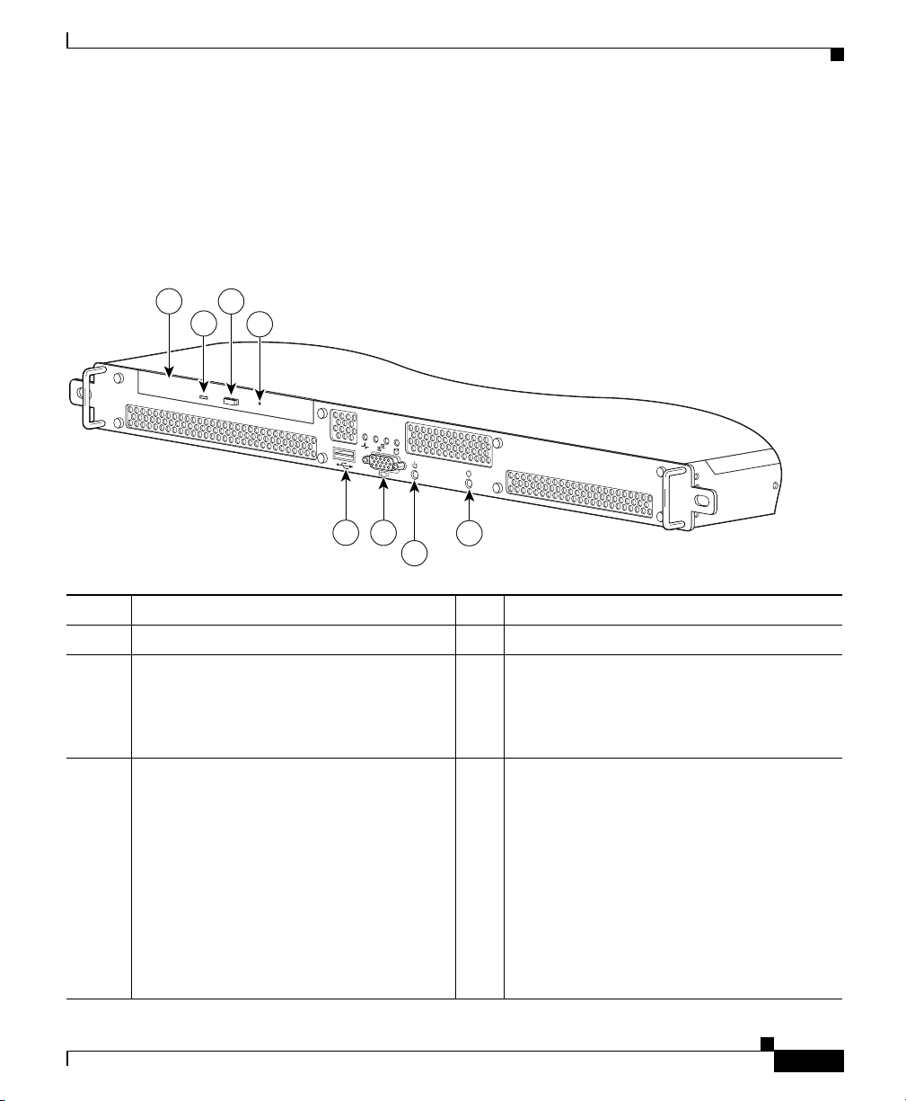
The GSS front panel contains LED indicators, a power button, and a CD-ROM
drive. Figure 1-1 illustrates the GSS front panel.
Figure 1-1 Front Panel View
1
3
2
4
System Hardware Features
0
1
i
119602
5
6
8
7
1 CD-ROM drive 5 USB port (not supported)
2 CD-ROM indicator 6 VGA port (not supported)
3 CD-ROM eject button 7 Power button with built-in power indicator.
The power button turns power on or off. To
turn chassis power off, press and hold this
switch for approximately four seconds.
4 CD-ROM emergency eject button 8 System ID button. The System ID button
allows you to identify the GSS when it is
installed in a single rack with multiple GSS
devices. The LED illuminates on the rear
panel of the active GSS.
• Press the front System ID button to
activate the blue LED on the rear panel
of the GSS.
• Press the rear System ID button to turn
off the LED on the rear panel.
Cisco Global Site Selector 4491 Hardware Installation Guide
78-16356-01
1-3
Page 26
System Hardware Features
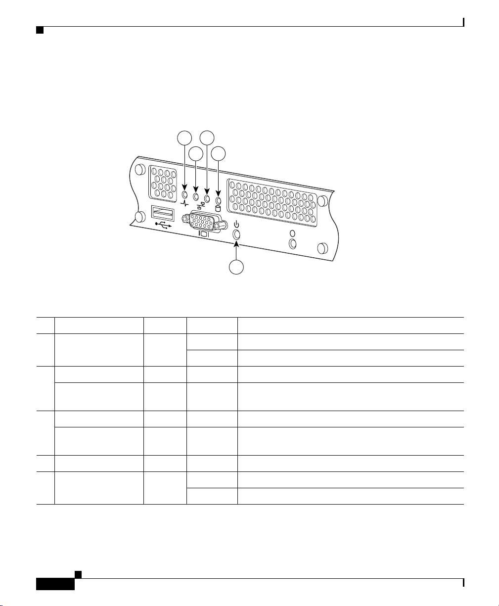
Figure 1-2 shows the LED indicators on the front panel of the GSS. Table 1 - 1
describes their function.
Figure 1-2 LED Indicators
Chapter 1 Introduction
3
1
4
2
0
1
i
5
119603
Table 1-1 Front Panel LED Indicators
Indicator Color State Indicates
1 Power Spike Blue On Normal operation
Blinking A power surge has occurred
2 Ethernet 0 Link Green On Ethernet 0 is connected to a network
Ethernet 0 Activity Green Blinking An active link connection on the
10/100/1000BASE-T interface for Ethernet port 0
3 Ethernet 1 Link Green On Ethernet 1 is connected to a network
Ethernet 1 Activity Green Blinking An active link connection on the
10/100/1000BASE-T interface for Ethernet port 1
4 Hard Drive Activity Green Blinking The hard drive is in use
5 Power Green On The GSS is on
Blinking The GSS is in standby mode
1-4
Cisco Global Site Selector 4491 Hardware Installation Guide
78-16356-01
Page 27
Chapter 1 Introduction
Rear Panel Features
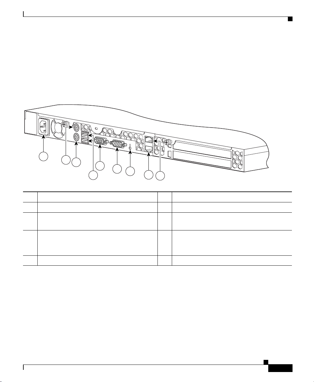
The rear panel contains the AC power receptacle, Ethernet connectors, and the
console/serial connector. Figure 1-3 illustrates the rear panel ports and
connectors.
Figure 1-3 Rear Panel View
System Hardware Features
i
1
2
3
5
6
7
4
8
9
1 AC power receptacle 6 VGA port (not supported)
2 PS/2 mouse port (not supported) 7 System ID button/System status LED
3 PS/2 keyboard port (not supported) 8 RJ-45 Ethernet 1 connector with
10/100/1000-Mbit/s operation
4 USB ports (not supported) 9 RJ-45 Ethernet 0 connector with
10/100/1000-Mbit/s operation and status
LEDs
5 Console/serial connector (see Figure 1-4)
119604
78-16356-01
Cisco Global Site Selector 4491 Hardware Installation Guide
1-5
Page 28
Ports and Connectors
Ports and Connectors
The GSS supports the following port connectors on the rear of the chassis:
• Console Port
• Ethernet Connectors
Chapter 1 Introduction
Warning
Console Port
To avoid electric shock, do not connect safety extra-low voltage (SELV) circuits
to telephone-network voltage (TNV) circuits. LAN ports contain SELV circuits,
and WAN ports contain TNV circuits. Some LAN and WAN ports both use RJ-45
connectors. Use caution when connecting cables.
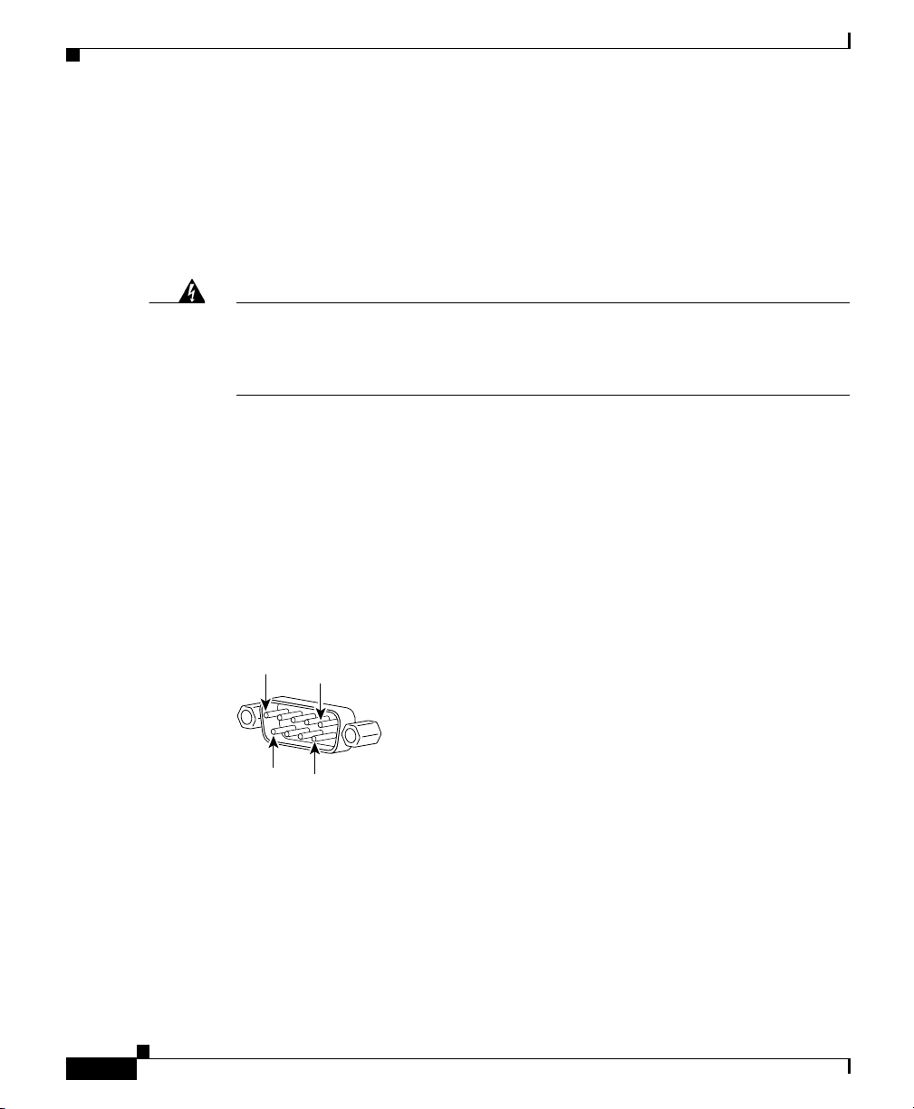
The GSS has one standard RS-232 serial port located on the rear panel that
operates as the console port. The integrated serial port uses a 9-pin male D-shell
connector. Figure 1-4 shows the pin number assignments for the 9-pin port.
Refer to Table 1 - 3 for the console port connector pinouts.
Figure 1-4 Console Port Connector Pin Numbers
1
5
6
9
119657
1-6
Cisco Global Site Selector 4491 Hardware Installation Guide
78-16356-01
Page 29

Chapter 1 Introduction
Ports and Connectors
Table 1-2 Console Port Connector Pinouts
Pin Signal I/O Definition
1 DCD I Data carrier detect
2 SIN I Serial input
3 SOUT O Serial output
4 DTR O Data terminal ready
5 GND N/A Signal ground
6 DSR I Data set ready
7 RTS O Request to send
8 CTS I Clear to send
9 RI I Ring indicator
Shell N/A N/A Chassis ground
78-16356-01
The console port operates at the settings outlined in Tab le 1-3. These settings are
not user-configurable.
Table 1-3 GSS Console Port Settings
Parameters Settings
Baud 9600
Data Bits 8
Parity None
Stop Bits 1
Terminal Type VT100/ANSI
Flow Control None
Cisco Global Site Selector 4491 Hardware Installation Guide
1-7
Page 30
Ports and Connectors
Ethernet Connectors
The GSS has two integrated 10/100/1000–megabit-per-second (Mbps) Ethernet
connectors. The Ethernet controller provides an interface for connecting to
10-Mbps, 100-Mbps, or 1000-Mbps networks and supports autonegotitate,
full-duplex, or half-duplex operation on an Ethernet LAN.
To access the Ethernet port, connect a Category 3, 4, or 5 unshielded twisted-pair
(UTP) cable to the RJ-45 connector on the back of the chassis.
Note The 100BASE-TX/1000BASE-TX Ethernet standard requires that you use
standard four twisted-pair Category 5e cable at lengths up to 328.08 ft. (100 m).
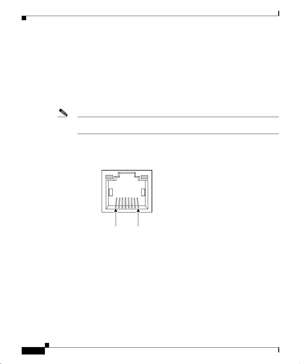
Figure 1-5 illustrates the pin number assignments for the Ethernet 0 RJ-45 port.
Figure 1-5 Ethernet Port 0 Pin Numbers
Chapter 1 Introduction
1-8
Link LED
(green)
8
Cisco Global Site Selector 4491 Hardware Installation Guide
Activity (TX/RX)LED
(green)
97447
1
78-16356-01
Page 31

CHAP T E R
2
Preparing for Installation
This chapter contains important safety information you should review before
working with the GSS. Use the following guidelines to ensure your own personal
safety and to help protect your GSS from potential damage.
Read the Regulatory Compliance and Safety Information for the Cisco Global Site
Selector 4491 document before you prepare the GSS for installation. This
document is included in the GSS accessory kit.
This chapter contains the following major sections:
• Safety
• Preparing Your Site for Installation
• Precautions for Rack-Mounting
• Precautions for Products with Modems, Telecommunications, or Local Area
Network Options
78-16356-01
• Required Tools and Equipment
Cisco Global Site Selector 4491 Hardware Installation Guide
2-1
Page 32

Safety
Safety
This section provides safety information for installing the GSS. It includes the
following topics:
• Warnings and Cautions
• General Precautions
• Maintaining Safety with Electricity
• Protecting Against Electrostatic Discharge
Warnings and Cautions
Read the installation instructions in this document before you connect the GSS to
its power source. Failure to read and follow these guidelines may lead to an
unsuccessful installation and possibly damage the GSS and components.
You should observe the following safety guidelines when working with any
equipment that connects to electrical power or telephone wiring. They can help
you avoid injuring yourself or damaging the GSS.
Chapter 2 Preparing for Installation
2-2
Note The English warnings in this document are followed by a statement number. To
see the translations of a warning into other languages, look up its statement
number in the Regulatory Compliance and Safety Information for the Cisco
Global Site Selector 4491.
Cisco Global Site Selector 4491 Hardware Installation Guide
78-16356-01
Page 33

Chapter 2 Preparing for Installation
The following warnings and cautions are provided to help you prevent injury to
yourself or damage to the devices:
Safety
Warning
Warning
Warning
IMPORTANT SAFETY INSTRUCTIONS
This warning symbol means danger. You are in a situation that could cause
bodily injury. Before you work on any equipment, be aware of the hazards
involved with electrical circuitry and be familiar with standard practices for
preventing accidents. Use the statement number provided at the end of each
warning to locate its translation in the translated safety warnings that
accompanied this device.
Statement 1071
SAVE THESE INSTRUCTIONS
The safety cover is an integral part of the product. Do not operate the unit
without the safety cover installed. Operating the unit without the cover in place
will invalidate the safety approvals and pose a risk of fire and electrical
hazards.
Statement 117
This equipment must be grounded. Never defeat the ground conductor or
operate the equipment in the absence of a suitably installed ground conductor.
Contact the appropriate electrical inspection authority or an electrician if you
are uncertain that suitable grounding is available.
Statement 1024
78-16356-01
Warning
Warning
Before working on a chassis or working near power supplies, unplug the power
cord on AC units; disconnect the power at the circuit breaker on DC units.
Statement 12
Before opening the chassis, disconnect the telephone-network cables to avoid
contact with telephone-network voltages.
Cisco Global Site Selector 4491 Hardware Installation Guide
Statement 1041
2-3
Page 34

Safety
Chapter 2 Preparing for Installation
Warning
Warning
Warning
Warning
This unit might have more than one power cord. To reduce the risk of electrical
shock, disconnect all power supply cords before servicing the unit.
Statement
106
This product requires short-circuit (overcurrent) protection, to be provided as
part of the building installation. Install only in accordance with national and
local wiring regulations.
Statement 1045
This equipment is intended to be grounded to comply with emission and
immunity requirements. Ensure that the switch functional ground lug is
connected to earth ground during normal use.
Statement 1064
Blank faceplates and cover panels serve three important functions: they
prevent exposure to hazardous voltages and currents inside the chassis; they
contain electromagnetic interference (EMI) that might disrupt other equipment;
and they direct the flow of cooling air through the chassis. Do not operate the
system unless all cards, faceplates, front covers, and rear covers are in place.
Statement 1029
2-4
Warning
Warning
Do not work on the system or connect or disconnect cables during periods of
lightning activity.
Statement 1001
The power supply circuitry for the equipment can constitute an energy hazard.
Before you install or replace the equipment, remove all jewelry (including
rings, necklaces, and watches). Metal objects can come into contact with
exposed power supply wiring or circuitry inside the DSLAM equipment. This
could cause the metal objects to heat up and cause serious burns or weld the
metal object to the equipment.
Cisco Global Site Selector 4491 Hardware Installation Guide
.
Statement 207
78-16356-01
Page 35

Chapter 2 Preparing for Installation
Safety
Warning
Warning
Warning
Warning
Ultimate disposal of this product should be handled according to all national
laws and regulations.
Statement 1040
Before working on a system that has an On/Off switch, turn OFF the power and
unplug the power cord.
Statement 1
Read the installation instructions before you connect the system to its power
source.
Statement 1004
There is the danger of explosion if the battery is replaced incorrectly. Replace
the battery only with the same or equivalent type recommended by the
manufacturer. Dispose of used batteries according to the manufacturer’s
instructions.
Statement 1015
78-16356-01
Cisco Global Site Selector 4491 Hardware Installation Guide
2-5
Page 36

Safety
General Precautions
Observe the following general precautions when using and working with your
GSS:
• Keep your GSS components away from radiators and heat sources, and do not
block cooling vents.
• Do not spill food or liquids on your GSS components, and never operate the
product in a wet environment. If the GSS gets wet, see Chapter 4,
Troubleshooting the GSS Hardware or contact the Cisco Technical Assistance
Center. For instructions on contacting the Technical Assistance Center, see
the Preface.
• Do not push any objects into the openings of your GSS components. Doing
so can cause fire or electric shock by shorting out interior components.
• Position cables and power cables carefully; route all cables and the power
cable and plug so that they cannot be stepped on or tripped over. Be sure that
nothing rests on your GSS cables or the power cable.
• Do not modify power cables or plugs. Consult a licensed electrician or your
power company for site modifications. Always follow your local/national
wiring rules.
• To help avoid possible damage to the system board, wait 5 seconds after
turning off the GSS before removing a component from the system board or
disconnecting a peripheral device from the GSS.
Chapter 2 Preparing for Installation
Maintaining Safety with Electricity
Follow these guidelines when working on equipment powered by electricity:
• If any of the following conditions occur contact the Cisco Technical
Assistance Center:
–
The power cable or plug is damaged.
–
An object has fallen into the product.
–
The product has been exposed to water.
–
The product has been dropped or damaged.
–
The product does not operate correctly when you follow the operating
instructions.
Cisco Global Site Selector 4491 Hardware Installation Guide
2-6
78-16356-01
Page 37

Chapter 2 Preparing for Installation
• Use the correct external power source. Operate the product only from the type
of power source indicated on the electrical ratings label. If you are not sure
of the type of power source required, consult the Cisco Technical Assistance
Center or a local power company.
• Use only approved power cable(s). You have been provided with a power
cable for your GSS that is intended for its use (approved for use in your
country, based on the shipping location). Should you have to purchase a
power cable, ensure that it is rated for the product and for the voltage and
current marked on the product’s electrical ratings label. The voltage and
current rating of the cable should be greater than the ratings marked on the
product.
• To help prevent electric shock, plug the GSS, components, and peripheral
power cables into properly grounded electrical outlets. These cables are
equipped with three-prong plugs to help ensure proper grounding. Do not use
adapter plugs or remove the grounding prong from a cable.
• Observe power strip ratings. Make sure that the total ampere rating of all
products plugged into the power strip does not exceed 80% of the rating.
• To help protect your GSS and components from sudden, transient increases
and decreases in electrical power, use a surge suppressor, line conditioner, or
uninterruptible power supply (UPS).
Safety
• Do not modify power cables or plugs. Consult a licensed electrician or your
power company for site modifications. Always follow your local and national
wiring rules.
Protecting Against Electrostatic Discharge
Static electricity can harm delicate components inside your computer. To prevent
static damage, discharge static electricity from your body before you touch any of
your computer’s electronic components, such as the microprocessor. You can do
so by touching an unpainted metal surface on the computer chassis.
As you continue to work inside the computer, periodically touch an unpainted
metal surface to remove any static charge your body may have accumulated.
Cisco Global Site Selector 4491 Hardware Installation Guide
78-16356-01
2-7
Page 38

Preparing Your Site for Installation
You can also take the following steps to prevent damage from electrostatic
discharge (ESD):
• When unpacking a static-sensitive component from its shipping carton, do not
remove the component from the antistatic packing material until you are
ready to install the component in your computer. Just before unwrapping the
antistatic packaging, be sure to discharge static electricity from your body.
• When transporting a sensitive component, first place it in an antistatic
container or packaging.
• Handle all sensitive components in a static-safe area. If possible, use
antistatic floor pads and workbench pads.
Preparing Your Site for Installation
This section describes the requirements your site must meet for safe installation
and operation of your GSS. Before you select an installation site for the GSS, read
the electrical, environmental, and physical requirements as described in
Appendix A, Specifications. Ensure that your site is properly prepared before
beginning installation.
Chapter 2 Preparing for Installation
2-8
This section includes the following requirements:
• Environmental
• Choosing a Site for Installation
• Ensuring Overcurrent Protection
• Grounding the GSS
• Creating a Safe Environment
• AC Power
• Cabling
Cisco Global Site Selector 4491 Hardware Installation Guide
78-16356-01
Page 39

Chapter 2 Preparing for Installation
Environmental
When planning your site layout and equipment locations, remember the
precautions described in this section to help avoid equipment failures and reduce
the possibility of environmentally caused shutdowns. If you are experiencing
shutdowns or unusually high errors with your existing equipment, these
precautions will help you isolate the cause of failures and prevent future
problems.
Use the following precautions when planning the operating environment for your
GSS.
• Always follow the ESD-prevention procedures described in the “Protecting
• Make sure that the chassis cover is secure. The chassis allows cooling air to
• Electrical equipment generates heat. Ambient air temperature might not be
Preparing Your Site for Installation
Against Electrostatic Discharge”section to avoid damage to equipment.
Damage from static discharge can cause immediate or intermittent equipment
failure.
flow effectively within it. An open chassis allows air leaks, which could
interrupt and redirect the flow of cooling air from internal components.
adequate to cool equipment to acceptable operating temperatures without
adequate circulation. Make sure that the room in which you operate has
adequate air circulation.
Choosing a Site for Installation
Warning
78-16356-01
This unit is intended for installation in restricted access areas. A restricted
access area is where access can only be gained by service personnel through
the use of a special tool, lock and key, or other means of security, and is
controlled by the authority responsible for the location.
• Choose a site with a dry, clean, well-ventilated and air-conditioned area.
• Choose a site that maintains an ambient temperature of 10° to 35°C
(50° to 95°F).
Cisco Global Site Selector 4491 Hardware Installation Guide
2-9
Page 40

Preparing Your Site for Installation
Ensuring Overcurrent Protection
The GSS relies on the protective devices in the building installation for protection
against short-circuit, overcurrent, and earth (grounding) fault. Ensure that the
protective devices in the building installation are properly rated to protect the
GSS, and that they comply with national and local codes.
Grounding the GSS
Chapter 2 Preparing for Installation
Warning
Never defeat the ground conductor or operate the equipment in the absence of
a suitably installed ground conductor. Contact the appropriate electrical
inspection authority or an electrician if you are uncertain that suitable
grounding is available.
Creating a Safe Environment
Follow these guidelines to create a safe operating environment:
• Keep tools and chassis components off the floor and away from foot traffic.
• Clear the area of possible hazards, such as moist floors, ungrounded power
extension cables, and missing safety grounds.
• Keep the area around the chassis free from dust and foreign conductive
material (such as metal flakes from nearby construction activity).
AC Power
Ensure that the plug-socket combination is accessible at all times, because it
serves as the main disconnecting device. Refer to Appendix A, Specifications, for
the GSS power requirements.
2-10
Warning
Cisco Global Site Selector 4491 Hardware Installation Guide
This product requires short-circuit (overcurrent) protection, to be provided as
part of the building installation. Install only in accordance with national and
local wiring regulations.
78-16356-01
Page 41

Chapter 2 Preparing for Installation
Cabling
Use the cables in the accessory kit to connect the GSS console port to a console
or computer that is running a console program. In addition to using the console
cable, use the provided standard Ethernet cable to connect the GSS to your
network. Refer to Chapter 1, Introduction, for information on cable requirements.
Precautions for Rack-Mounting
Precautions for Rack-Mounting
Warning
Note Component refers to any server, storage system, or appliance, and to various
To prevent bodily injury when mounting or servicing this unit in a rack, you must
take special precautions to ensure that the system remains stable. The
following guidelines are provided to ensure your safety:
Observe the following precautions for rack stability and safety. Also refer to the
rack installation documentation accompanying the rack for specific warnings and
caution statements and procedures.
peripherals or supporting hardware.
• Do not move large racks by yourself. Due to the height and weight of the rack,
a minimum of two people are needed to accomplish this task.
• Ensure that the rack is level and stable before extending a component from
the rack.
• Do not overload the AC supply branch circuit that provides power to the rack.
The total rack load should not exceed 80% of the branch circuit rating.
• Ensure that proper airflow is provided to components in the rack.
• Do not step or stand on any system or component when servicing other
systems and components in a rack.
• This unit should be mounted at the bottom of the rack if it is the only unit in
the rack.
78-16356-01
Cisco Global Site Selector 4491 Hardware Installation Guide
2-11
Page 42

Chapter 2 Preparing for Installation
Precautions for Products with Modems, Telecommunications, or Local Area Network Options
• When mounting this unit in a partially filled rack, load the rack from the
bottom to the top with the heaviest component at the bottom of the rack.
• If the rack is provided with stabilizing devices, install the stabilizers before
mounting or servicing the unit in the rack.
Precautions for Products with Modems,
Telecommunications, or Local Area Network
Options
Observe the following guidelines when working with these components:
• Do not connect or use a modem or telephone during a lighting storm. There
may be a risk of electrical shock from lightning.
• Never connect or use a modem or telephone in a wet environment.
• Do not plug a modem or telephone cable into the Ethernet connector.
• Disconnect the modem cable before opening a product enclosure, touching or
installing internal components, or touching an uninsulate4d modem cable or
jack.
• Do not use a telephone line to report a gas leak while you are in the vicinity
of the leak.
Required Tools and Equipment
You need the following tools and equipment to install the GSS:
• Number 2 Phillips screwdriver
• Tape measure and level
• Antistatic mat or antistatic foam
• ESD grounding strap with an alligator termination clip
Cisco Global Site Selector 4491 Hardware Installation Guide
2-12
78-16356-01
Page 43

CHAP T E R
3
Installing the GSS
This chapter explains how to install a GSS in an equipment rack, or on a table or
workbench. This chapter also provides instructions for connecting cables, AC
power, and for booting the GSS.
78-16356-01
Warning
Read the installation instructions before connecting the GSS to the
power source.
This chapter contains the following major sections:
• Unpacking and Inspecting the GSS
• Installing Your GSS
• Connecting Cables
• Connecting AC Power
• Booting the GSS
• Establishing a Serial Console Connection
• Checking the Front Panel LEDs
• Removing or Replacing a GSS
Before you begin the installation, be sure you have read:
• Chapter 2, Preparing for Installation
• Regulatory Compliance and Safety Information for the Cisco Global Site
Selector 4491
Cisco Global Site Selector 4491 Hardware Installation Guide
3-1
Page 44

Unpacking and Inspecting the GSS
Unpacking and Inspecting the GSS
The GSS shipment contains the following items:
• One RJ-45 to female 25-pin sub-d connector
• Two RJ-45 to female 9-pin sub-d connectors
• One RJ-45 console cable
• One four-post rack mount kit
• One two-post rack mount kit
• Four rubber feet
• Cisco Product Documentation CD-ROM and Warranty Package
• Cisco Global Site Selector 4491 Hardware Installation Guide
• Regulatory Compliance and Safety Information for the Cisco Global Site
Selector 4491
The GSS is shipped in a protective shipping carton. It is shipped as a
self-contained chassis; no components can be added or removed.
Follow these steps to unpack the GSS:
Chapter 3 Installing the GSS
1. Remove the GSS accessories from the shipping carton. Save the packing
materials in case you need to repack the GSS later.
2. Check the configuration of the GSS and the accessories against the items
listed on the packing slip. Report any discrepancies as described in “If the
Product is Damaged”.
3. Before installing the GSS, review the information outlined in Chapter 2,
Preparing for Installation.
If the Product is Damaged
If any portion of the unit or component is damaged in transit, forward an
immediate request to the delivering carrier to perform an inspection of the product
and to prepare a damage report. Save the container and all packing materials until
the contents are verified.
Cisco Global Site Selector 4491 Hardware Installation Guide
3-2
78-16356-01
Page 45

Chapter 3 Installing the GSS
Concurrently, report the nature and extent of the damage to Customer Service.
Report the problem or deficiency to Customer Service along with the model
number and serial number. Upon receipt of this information, you will be provided
with service instructions, or a Return Material Authorization (RMA) number and
shipping information. To obtain assistance, refer to the “Preface”.
Installing Your GSS
Place the GSS in the desired location. You can mount it in a rack for your
convenience, or place it on a solid, stable surface. If you do not plan to install the
GSS in an equipment rack, proceed to the “Installing the GSS on a Workbench or
Tablet o p ” section.
Racks are marked in vertical increments of 1.75 inches (4.44 cm). Each increment
is referred to as a rack unit (RU). A 1-RU device is 1.75 inches (4.44 cm) tall.
Installing Your GSS
78-16356-01
Warning
To prevent bodily injury when mounting or servicing this unit in a rack, you must
take special precautions to ensure that the GSS remains stable. The following
guidelines are provided to ensure your safety:
This unit should be mounted at the bottom of the rack if it is the only unit in the
rack.
When mounting this unit in a partially filled rack, load the rack from the bottom
to the top with the heaviest component at the bottom of the rack.
If the rack is provided with stabilizing devices, install the stabilizers before mounting or
servicing the unit in the rack.
Statement 1006
This section contains the following procedures:
• Installing the GSS in a Four-Post Rack
• Attaching a Two-Post Rack Bracket to the GSS
• Installing the GSS on a Workbench or Tabletop
Cisco Global Site Selector 4491 Hardware Installation Guide
3-3
Page 46

Installing Your GSS
Installing the GSS in a Four-Post Rack
This section provides instructions for installing the GSS in a four-post rack. The
rack must be properly secured to the floor, ceiling, or upper wall, and where
applicable, to adjacent racks. The rack should be secured using floor and wall
fasteners and bracing as specified by industry standards.
Before installing the GSS in a rack, be sure you have read Chapter 2, Preparing
for Installation, to familiarize yourself with the proper site and environmental
conditions. Failure to read and follow these guidelines may lead to an
unsuccessful installation and possible damage to the GSS and its components.
Perform the steps below when installing and servicing the GSS.
When installing and servicing the GSS:
• Disconnect all power and external cables before installing the GSS.
• Install the GSS in compliance with your local and national electrical codes:
–
United States: National Fire Protection Association (NFPA) 70; United
States National Electrical Code.
–
Canada: Canadian Electrical Code, Part, I, CSA C22.1.
Chapter 3 Installing the GSS
3-4
–
Other countries: If local and national electrical codes are not available,
see IEC 364, Part 1 through Part 7.
• Do not work alone under potentially hazardous conditions.
• Do not perform any action that creates a potential hazard to people or makes
the equipment unsafe.
• Do not attempt to install the GSS in a rack that has not been securely anchored
in place. Damage to the GSS and personal injury may result.
• Due to the size and weight of the GSS, never attempt to install it by yourself.
Refer to Chapter 2, Preparing for Installation, the “Precautions for
Rack-Mounting” section for additional safety information on rack installation.
Cisco Global Site Selector 4491 Hardware Installation Guide
78-16356-01
Page 47
Chapter 3 Installing the GSS
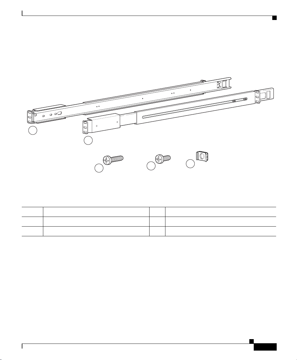
The GSS can be installed in a system 1U rack. Figure 3-1 illustrates the four-post
rack rail components. Tab le 3-1 describes each four-post rack rail component.
Figure 3-1 Rack Rail Components
1
2
3
Installing Your GSS
119960
4
5
Table 3-1 Four-Post Rack Components
1 Left side telescopic rail 4 Round head screws (6)
2 Right side telescopic rail 5 Cage nuts (6)
3 Round head screws with washer (9)
The procedure to install the GSS into a four-post rack is divided into two parts:
• Attaching the Telescopic Rails to the Rack Assembly
• Inserting the GSS into the Rack
To install the GSS in a four-post rack by using a two-post rack bracket, see the
“Attaching a Two-Post Rack Bracket to the GSS” section.
Cisco Global Site Selector 4491 Hardware Installation Guide
78-16356-01
3-5
Page 48
Installing Your GSS
Attaching the Telescopic Rails to the Rack Assembly
To attach the telescopic rails to the four-post rack assembly:
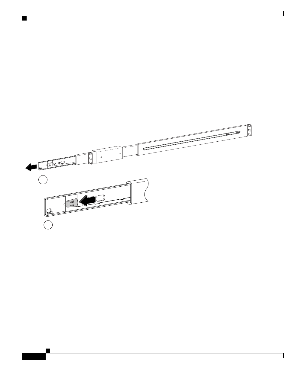
1. Extend the rail (1) as far as it will go, as shown in Figure 3-2.
2. Press the green spring plate (2) on the extended telescopic rail and remove the
inner rail. Set the rail aside for attachment to the GSS (see the “Inserting the
GSS into the Rack” section).
Figure 3-2 Removing the Inner Server Rail
1
Chapter 3 Installing the GSS
3-6
119961
2
Cisco Global Site Selector 4491 Hardware Installation Guide
78-16356-01
Page 49
Chapter 3 Installing the GSS
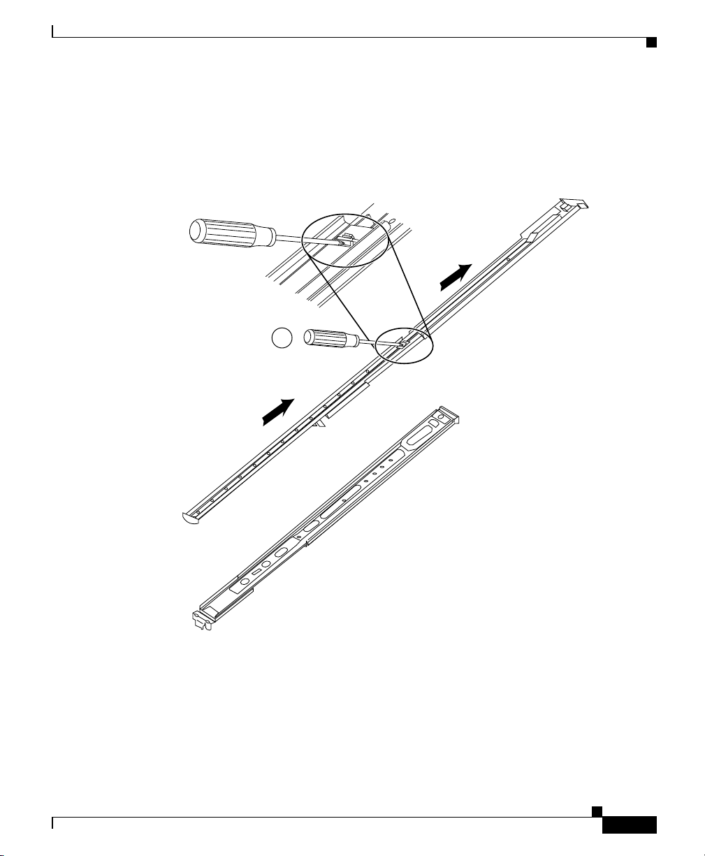
3. Using a screwdriver (1), gently press the button labelled “Push” and move the
Figure 3-3 Telescoping the Rail
Installing Your GSS
middle section of the outer telescopic rail to its end position, as shown in
Figure 3-3.
1
78-16356-01
99522
Cisco Global Site Selector 4491 Hardware Installation Guide
3-7
Page 50
Installing Your GSS
Chapter 3 Installing the GSS
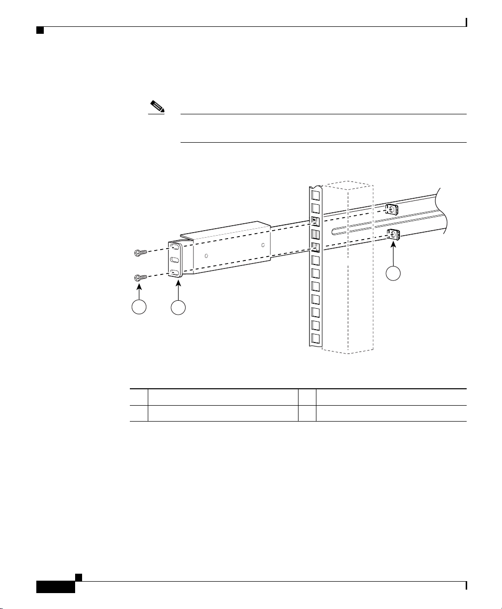
4. Select a location in the rack to mount the GSS and attach the front end of the
right outer telescopic rail to the right side of the rack, as show in Figure 3-4.
Note Racks that contain tapped mounting holes do not require the cage
nuts (3) shown in Figure 3-4.
Figure 3-4 Attaching Front Rail to the Right Side of the Rack
3
3-8
1
2
1 Round head screw and washer 3 Cage nut
2 Right outer telescopic rail—front
5. Extend the middle rail from the front of the rack to have free access to the two
adjustment screws located at the rear of the outer telescopic rail (Figure 3-5).
Loosen the two adjustment screws to leave some play when attaching the
back end of the outer telescopic rail to the rack, then push the middle rail back
into its original position. After the rail is attached to the rack, you can tighten
the two adjustment screws.
Cisco Global Site Selector 4491 Hardware Installation Guide
119962
78-16356-01
Page 51
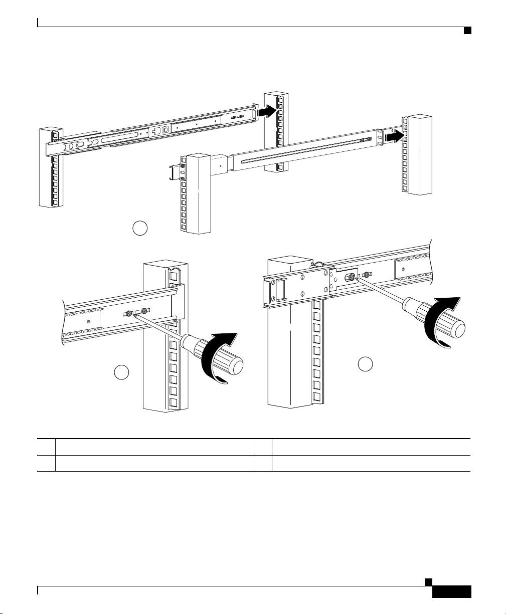
Chapter 3 Installing the GSS
Figure 3-5 Telescopic Rail Adjustment Screws
1
Installing Your GSS
2
3
1 Right and left rails 3 Right rail adjustment screws
2 Left rail adjustment screws
Cisco Global Site Selector 4491 Hardware Installation Guide
78-16356-01
119964
3-9
Page 52
Installing Your GSS
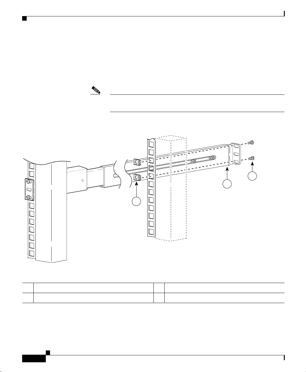
6. Position and align the back end of the outer telescopic rail with the right side
of the rack. Ensure that the back end of the rail is aligned with the front end
and that it is flush with the rack post.
7. Attach the back end of the rail to the right side of the rack, as shown in
Figure 3-6.
Note Racks that contain tapped mounting holes do not require the cage
nuts (3) shown in Figure 3-6.
Figure 3-6 Attaching Back Rail to the Right Side of the Rack
Chapter 3 Installing the GSS
1
2
3
1 Round head screw and washer 3 Cage nut
2 Right outer telescopic rail—rear
Cisco Global Site Selector 4491 Hardware Installation Guide
3-10
119963
78-16356-01
Page 53
Chapter 3 Installing the GSS
8. Repeat steps 1 through 7 with the left side rail and rack assembly.
9. Tighten the two adjustment screws located at the rear of the two outer
telescopic rails (see Figure 3-5).
Inserting the GSS into the Rack
To insert the GSS into the four-post rack:
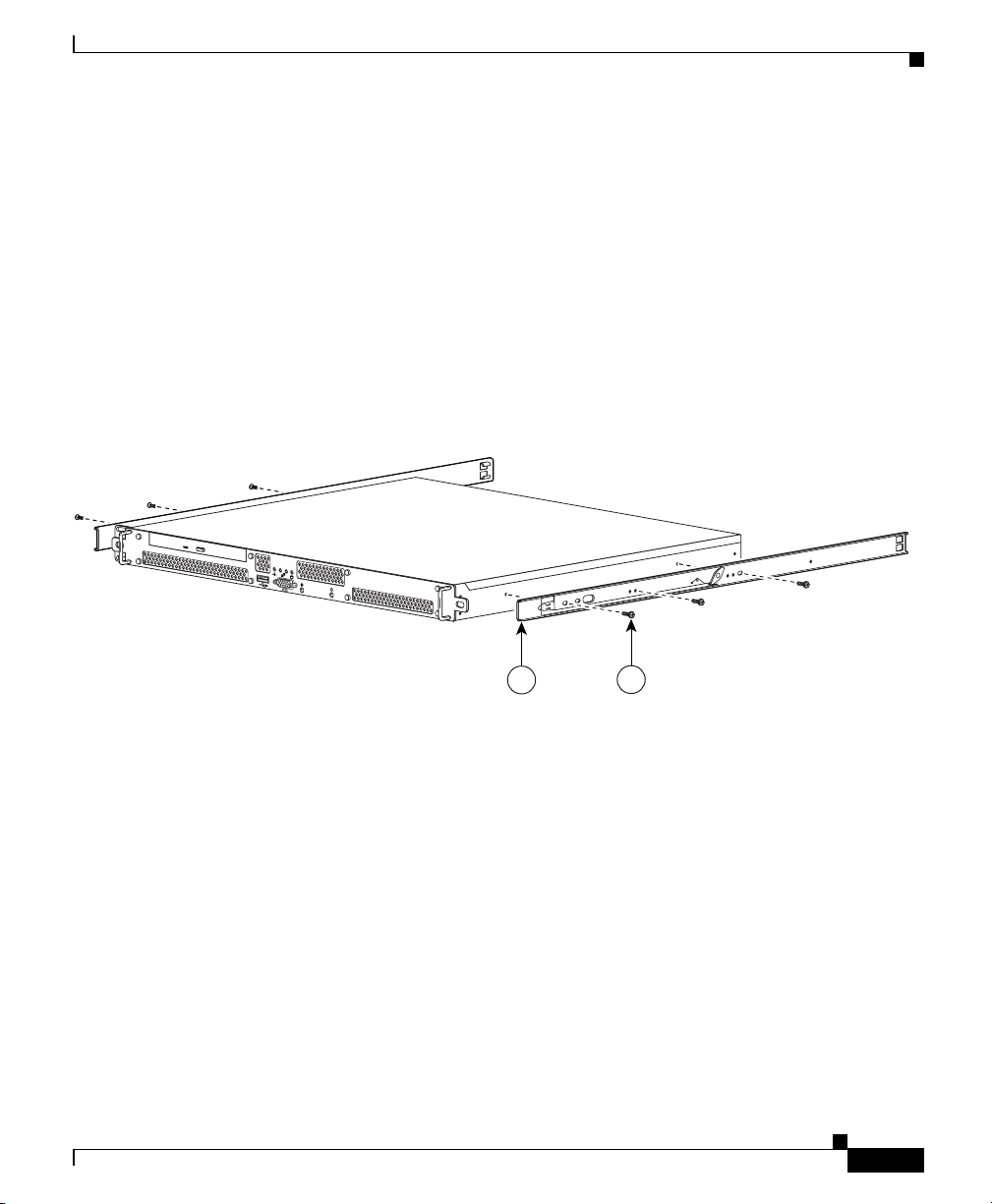
1. Secure the inner rail (1) to GSS using three round head screws (2), as shown
in Figure 3-7. Repeat this step for
Figure 3-7 Attaching GSS to Right Rail
0
1
i
Installing Your GSS
the other rail.
78-16356-01
1
Cisco Global Site Selector 4491 Hardware Installation Guide
2
119965
3-11
Page 54
Installing Your GSS
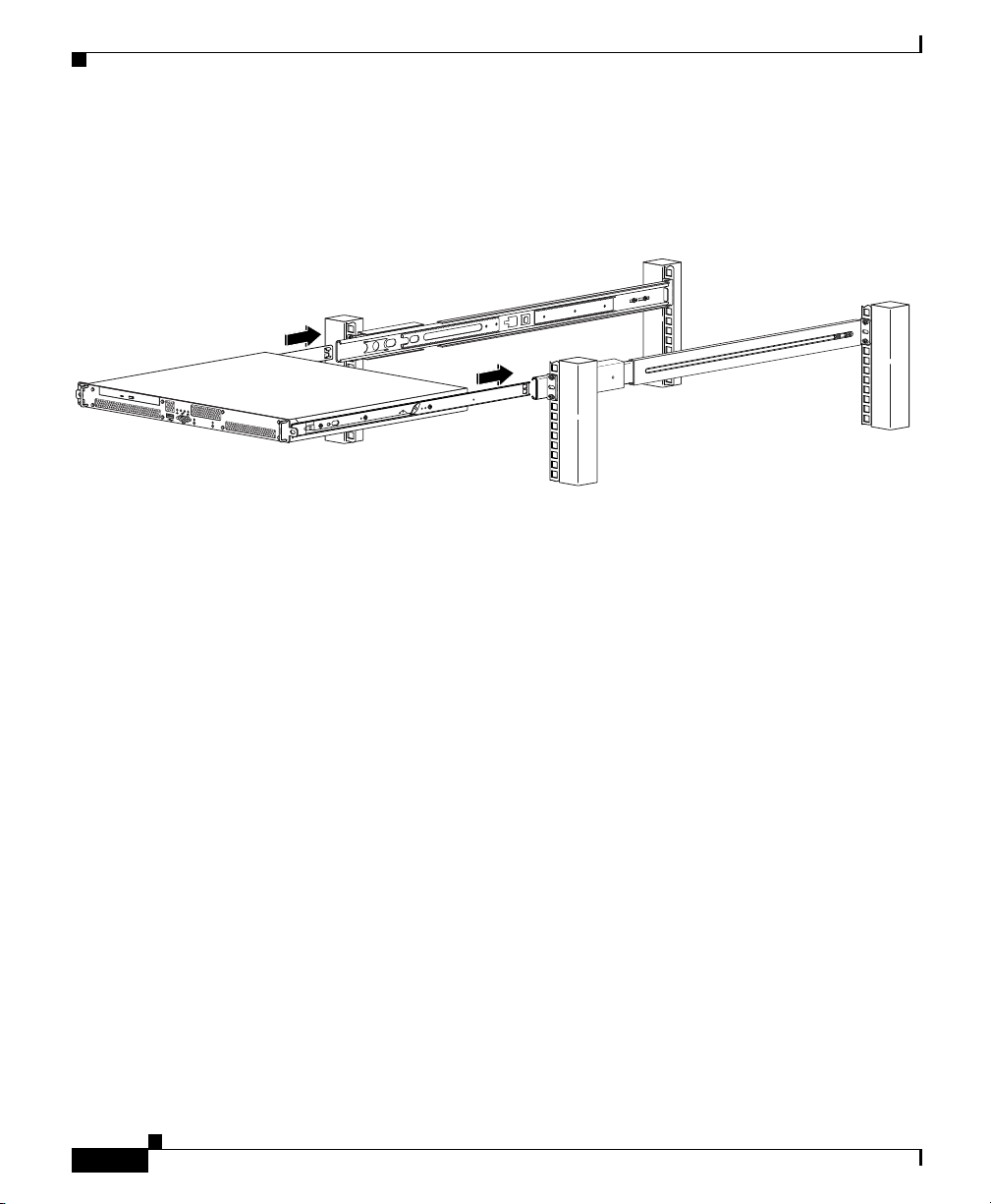
2. Insert the GSS and inner rail into the two outer telescopic rails, as shown in
Figure 3-8.
Figure 3-8 Sliding the GSS into the Four-post Rack
0
1
i
Slide the GSS and inner rails backward and forward in the two outer
3.
telescopic rail two or three times until the GSS seats properly in the rack.
Chapter 3 Installing the GSS
120000
Attaching a Two-Post Rack Bracket to the GSS
You may install the GSS in either a four-post rack or a two-post rack by using the
two-post rack bracket included in the accessory kit.
To attach a two-post rack bracket to the GSS:
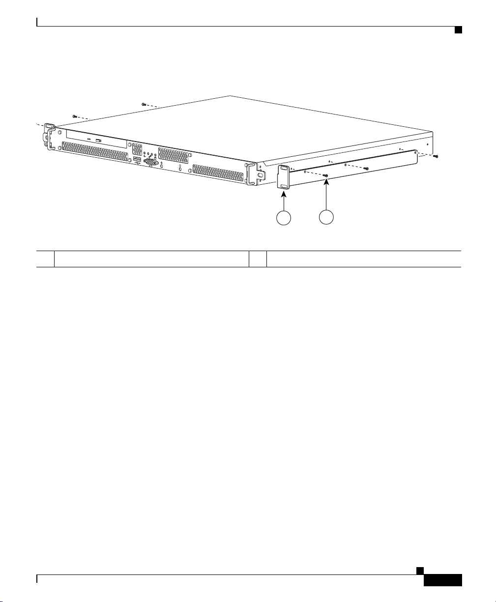
1. Place the right-hand bracket on the right side of the GSS as shown in
Figure 3-9. Align the bracket with the three screw holes in the GSS and use
three round head screws to secure the bracket.
Repeat this step to attach the other bracket to the GSS.
Cisco Global Site Selector 4491 Hardware Installation Guide
3-12
78-16356-01
Page 55
Chapter 3 Installing the GSS
Figure 3-9 Attaching the Right Bracket to the Right Side of the GSS
0
1
i
Installing Your GSS
119959
1
2
1 Bracket 2 Round head screws (6)
Select a location in the rack to mount the GSS, then position the GSS and
2.
brackets in the rack.
3. Align the right side bracket on the GSS to the front of the rack, then insert
and tighten the two round head retaining screws to secure the GSS to the rack.
Repeat this step to secure the left side bracket to the rack.
78-16356-01
Cisco Global Site Selector 4491 Hardware Installation Guide
3-13
Page 56

Installing Your GSS
Installing the GSS on a Workbench or Tabletop
When you install a GSS on a workbench or tabletop, ensure that the surface is
clean and in a secure location and that you have complied with the following
requirements:
• The chassis should be installed off the floor. Dust that accumulates on the
floor is drawn into the interior of the chassis by the cooling fans. Excessive
dust inside the GSS can cause overtemperature conditions and component
failures.
• There must be approximately 19 inches (48.26 cm) of clearance at the front
and rear of the chassis for accessing network cables and equipment.
• The GSS must receive adequate ventilation.
Follow these steps to install the GSS on a workbench or tabletop:
1. Remove any debris and dust from the tabletop or workbench, as well as from
the surrounding area. Ensure that your path between the GSS and its new
location is unobstructed.
2. Place one rubber foot in each corner on the bottom of the GSS. The rubber
feet have an adhesive backing. Peel the protective tape off the adhesive and
adhere the feet to the bottom of a clean chassis surface.
Chapter 3 Installing the GSS
3-14
3. Place the chassis on the tabletop or workbench.
4. Ensure that no exhaust air from other equipment will be drawn into the
chassis. Also, ensure that there is adequate clearance at the front and rear of
the chassis.
Cisco Global Site Selector 4491 Hardware Installation Guide
78-16356-01
Page 57
Chapter 3 Installing the GSS
Connecting Cables
Connecting Cables
Warning
Do not work on the GSS or connect or disconnect cables during periods of
lightning activity.
To connect network and console cables to your GSS 4491:
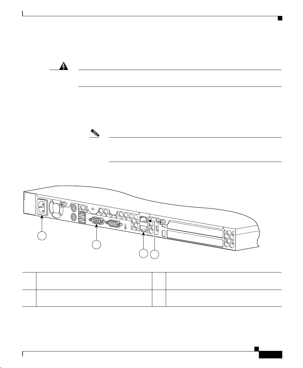
1. For network connections, connect a Category 3, 4, or 5 unshielded
twisted-pair (UTP) cable to the Ethernet 0 or Ethernet 1 connector on the GSS
back panel (Figure 3-10).
Note The 100BASE-TX/1000BASE-TX Ethernet standard requires that
you use standard four twisted-pair Category 5e cable at lengths up to
328.08 ft. (100 m).
Figure 3-10 GSS Back Panel Ports and Connectors
i
1
2
3
119605
4
1 AC power receptacle 3 RJ-45 Ethernet 1 connector with
10/100/1000-Mbit/s operation
2 Console/serial connector 4 RJ-45 Ethernet 0 connector with
10/100/1000-Mbit/s operation
Cisco Global Site Selector 4491 Hardware Installation Guide
78-16356-01
3-15
Page 58

Connecting AC Power
2. Connect the other end of the network cable to a hub or switch in your
network.
3. For console connections, plug the cable into the console port on the GSS back
panel.
4. Connect the other end of the console cable to a console or a
communications server.
Connecting AC Power
Chapter 3 Installing the GSS
Warning
This equipment must be grounded. Never defeat the ground conductor or
the equipment in the absence of a suitably installed ground conductor.
the appropriate electrical inspection authority or an electrician if you are uncertain
that suitable grounding is available.
Statement 1024
operate
Contact
To connect AC power to your GSS:
1. Ensure that you have reviewed the safety information outlined in Chapter 2,
Preparing for Installation.
2. Plug the AC power cord into the power cord receptacle at the rear of the GSS
(see Figure 3-10).
3. Connect the other end of the power cord to a power source.
4. Power up all externally-connected devices.
5. Press the power control button on the front of the GSS.
3-16
Cisco Global Site Selector 4491 Hardware Installation Guide
78-16356-01
Page 59

Chapter 3 Installing the GSS
Booting the GSS
When you power up the GSS, the boot process:
• Performs hardware initialization and power-on self tests
• Initializes the BIOS
• Initializes the Linux boot manager, LILO (Linux Loader)
• Boots the GSS image (kernel and software)
• Displays the startup banner and splash screen for strong encryption
• Prompts you to log in to the GSS
Note During power-up, the green power LED on the front of the GSS is on.
At this point, you are ready to use the GSS. Refer to the:
• Cisco Global Site Selector Getting Started Guide for details on setting up and
configuring the GSS device
Booting the GSS
78-16356-01
• Cisco Global Site Selector Administration Guide for procedures to properly
manage and maintain your GSSM and GSS devices
• Cisco Global Site Selector Global Server Load-Balancing Configuration
Guide for procedures to configure your GSS devices to perform global server
load balancing
If you are booting the GSS for the first time and it boots without a
startup-configuration file, a setup script automatically runs to guide you through
the process of initially configuring the GSS. Refer to the Cisco Global Site
Selector Getting Started Guide for details about using the setup script.
Cisco Global Site Selector 4491 Hardware Installation Guide
3-17
Page 60

Chapter 3 Installing the GSS
Establishing a Serial Console Connection
Establishing a Serial Console Connection
Before you configure the GSS, you should establish a serial console connection
to it. This requires a PC, two DB-9 to RJ-45 adapters (provided), an RJ-45 cable
(provided), and terminal emulation communication software (Hyper Terminal or
equivalent). You may also use a serial concentrator connection, if desired.
To establish a serial console connection:
1. Connect a console to the serial console port on the rear panel:
a. Attach a DB-9 to RJ-45 adapter to the serial port of the console.
b. Attach a DB-9 to RJ-45 adapter to the serial port of the GSS. For the
location of the serial port, see Figure 3-10.
c. Use an RJ-45 cable to connect the console to the GSS.
2. If you have not already done so, power up the GSS as described in the
“Booting the GSS” section.
3. Open your terminal emulation application on your PC to access the GSS CLI.
The following procedure uses HyperTerminal for Windows:
a. Launch HyperTerminal. The Connection Description window appears.
3-18
b. Enter a name for your session in the Name field.
c. Click OK. The Connect To window appears.
d. From the drop-down list, choose the COM port to which the device is
connected.
e. Click OK. The Port Properties window appears.
f. Set the port properties:
Baud Rate = 9600
Data Bits = 8
Flow Control = none
Parity = none
Stop Bits = 1
g. Click OK to connect.
h. Press Enter to display the CLI prompt.
Cisco Global Site Selector 4491 Hardware Installation Guide
78-16356-01
Page 61
Chapter 3 Installing the GSS
4. Once you create a session, choose Save As from the File menu to save the
connection description. Saving the connection description has the following
two advantages:
–
The next time you launch HyperTerminal, the session is listed as an
option under Start > Programs > Accessories > HyperTerminal >
Name_of_session. This option lets you reach the CLI prompt directly
without repeating the configuration steps.
–
You can connect your cable to a different device without configuring a
new HyperTerminal session. If you use this option, ensure that you
connect to the same port on the new device as was configured in the saved
HyperTerminal session. Otherwise, a blank screen appears without a
prompt.
Checking the Front Panel LEDs
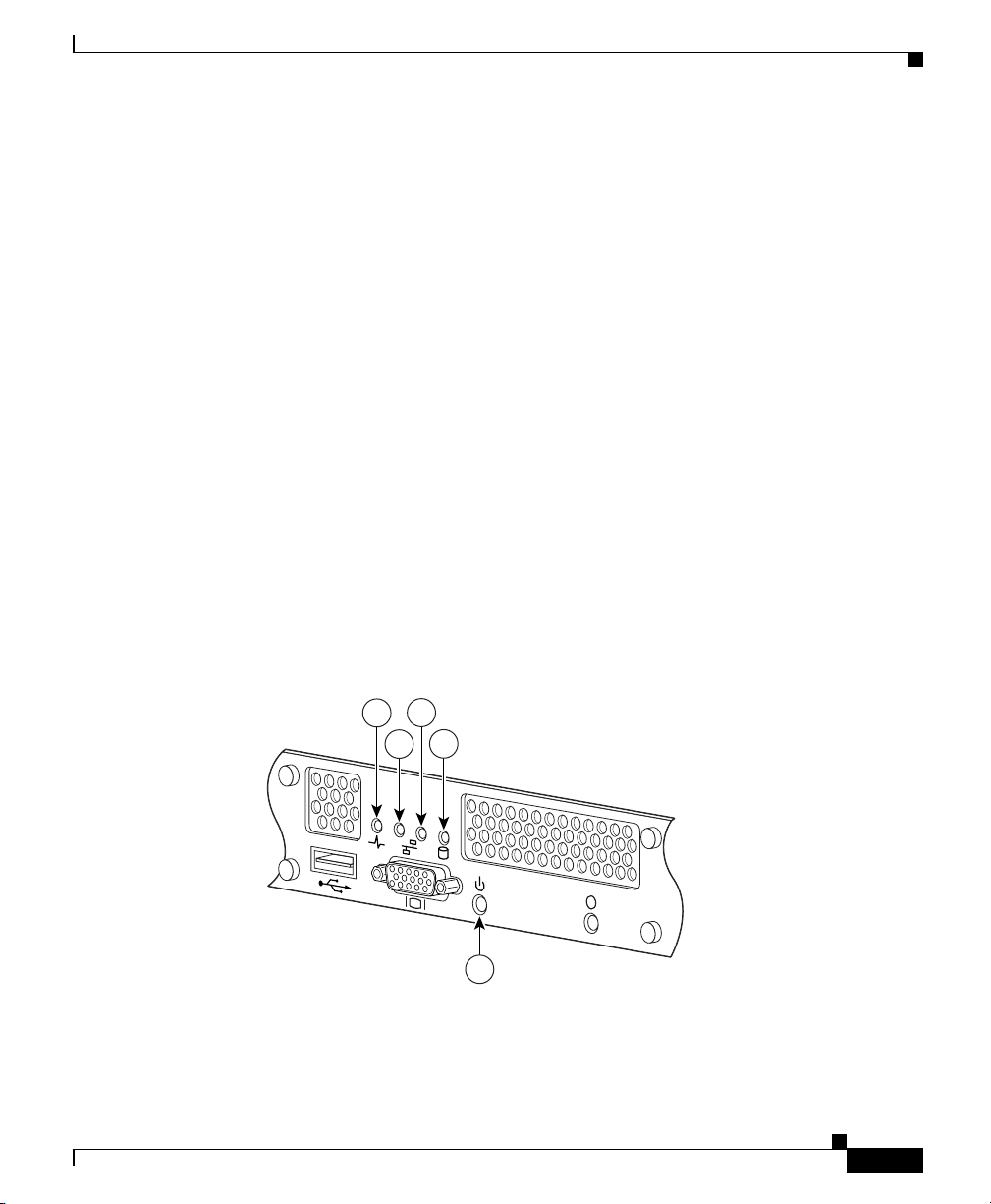
When the GSS is up and running, observe the front panel LEDs to monitor GSS
operating status. Figure 3-11 shows the location of front panel LEDs, and
Table 3-2 describes their function.
Checking the Front Panel LEDs
78-16356-01
Figure 3-11 GSS 4491 Front Panel LEDs
3
1
4
2
0
1
5
Cisco Global Site Selector 4491 Hardware Installation Guide
i
119603
3-19
Page 62

Chapter 3 Installing the GSS
Removing or Replacing a GSS
Table 3-2 Front Panel LED Indicators
Indicator Color State Indicates
1 Power Spike Blue On Normal operation
Blinking A power surge has occurred
2 Ethernet 0 Link Green On Ethernet 0 is connected to a network
Ethernet 0 Activity Green Blinking An active link connection on the
10/100/1000BASE-T interface for Ethernet port 0
3 Ethernet 1 Link Green On Ethernet 1 is connected to a network
Ethernet 1 Activity Green Blinking An active link connection on the
10/100/1000BASE-T interface for Ethernet port 1
4 Hard Drive Activity Green Blinking The hard drive is in use
5 Power Green On The GSS is on
Blinking The GSS is in standby mode
Removing or Replacing a GSS
Warning
Warning
Cisco Global Site Selector 4491 Hardware Installation Guide
3-20
Before working on a GSS, turn OFF the power and unplug the power cord.
Ultimate disposal of this product should be handled according to all national
laws and regulations.
Before physically removing or replacing a GSS, use the primary GSSM GUI to
logically remove the GSS from the network. You may need to logically remove a
GSS from your network when you:
• Move a GSS device between GSS networks
• Remove or replace a GSS or standby GSSM
• Send the GSS or standby GSSM out for repair or replacement
78-16356-01
Page 63

Chapter 3 Installing the GSS
For details about using the primary GSSM GUI to logically remove a GSS device
or the standby GSSM from the GSS network, refer to Chapter 1, Managing GSS
Devices from the GUI, in the Cisco Global Site Selector Administration Guide.
Note Do not logically remove the primary GSSM from the GSS network. If you need
to physically take the primary GSSM offline for either maintenance or repair,
temporarily switch the roles of the primary and standby GSSMs as outlined in the
Cisco Global Site Selector Administration Guide.
To physically remove a GSS from your network:
1. Power down the GSS by pressing the power button on the front panel of the
2. Disconnect the power cords and network cables.
3. Physically remove the chassis from the rack.
To physically replace a GSS, install the new GSS and configure it using the same
configuration parameters (such as IP address) that you used for the removed GSS.
Refer to the Cisco Global Site Selector Getting Started Guide for details.
Removing or Replacing a GSS
GSS.
78-16356-01
Cisco Global Site Selector 4491 Hardware Installation Guide
3-21
Page 64

Removing or Replacing a GSS
Chapter 3 Installing the GSS
3-22
Cisco Global Site Selector 4491 Hardware Installation Guide
78-16356-01
Page 65

Troubleshooting the GSS Hardware
If your GSS is not working as expected, begin troubleshooting using the
procedures in this chapter. This chapter guides you through some initial checks
and procedures that can solve basic GSS problems.
This chapter contains the following major sections:
• Checking the Basics
• Checking Connections
Checking the Basics
To solve some basic GSS problems, follow these steps:
1. Was an alert message issued by the GSS software?
CHAP T E R
4
78-16356-01
–
Ye s . Check the component named in the alert message.
–
No. Go to step 2.
Cisco Global Site Selector 4491 Hardware Installation Guide
4-1
Page 66

Checking Connections
Chapter 4 Troubleshooting the GSS Hardware
2. Visually inspect the GSS. Is the GSS wet or damaged?
–
Ye s . Liquid spills, splashes, and excessive humidity can cause damage to
the GSS. If a GSS gets wet, contact your service representative for
instructions. Refer to the Preface
If the GSS was dropped or damaged while being moved, you should
check it to see if it functions properly. If an external device attached to
the GSS is dropped or damaged, contact your service representative for
instructions. Refer to the Preface.
–
No. Go to step 3.
3. Perform the steps in the “Checking Connections” section.
Is the problem resolved?
–
Ye s . The power to the GSS was faulty, or the connections were loose. You
have fixed the problem.
–
No. Go to step 4.
4. Did the GSS complete the boot routine?
–
Ye s . The GSS configuration information was correct.
–
No. Call your service representative. Refer to the Preface.
Checking Connections
Loose, incorrect, or improperly connected cables are the most likely source of
problems for the GSS or other external equipment. A quick check of all the cable
connections can solve most problems. Refer to Chapter 1, Introduction, for the
location of the front panel controls and indicators and for the location of back
panel connections on the GSS.
To check all the connections:
1. Power down the GSS. Disconnect all the power cables from their electrical
outlets.
Cisco Global Site Selector 4491 Hardware Installation Guide
4-2
78-16356-01
Page 67

Chapter 4 Troubleshooting the GSS Hardware
2. If the GSS is connected to a power strip or power distribution unit, turn the
power strip off and then on again.
Is the power strip receiving power?
–
Ye s . Go to step 5.
–
No. Go to step 3.
3. Plug the power strip into another electrical outlet.
Is the power strip receiving power?
–
Ye s . The original electrical outlet probably does not function. Use a
different electrical outlet.
–
No. Go to step 4.
4. Connect a GSS that you know works into the electrical outlet.
Does the GSS receive power?
–
Ye s . The power strip is probably not functioning properly. Use another
power strip.
–
No. Go to step 5.
Checking Connections
78-16356-01
5. Reconnect the GSS to the electrical outlet or power strip.
Make sure that all connections fit tightly together. Ensure that the Ethernet
and Console cables are correct for use with the GSS (refer to Chapter 1,
Introduction).
6. Power up the GSS.
Is the problem resolved?
–
Ye s . The connections were loose. You have fixed the problem.
–
No. Call your service representative. Refer to the Preface.
Cisco Global Site Selector 4491 Hardware Installation Guide
4-3
Page 68

Checking Connections
Chapter 4 Troubleshooting the GSS Hardware
4-4
Cisco Global Site Selector 4491 Hardware Installation Guide
78-16356-01
Page 69

CHAP T E R
Maintaining Your GSS
Proper use of preventive maintenance procedures can keep the GSS in top
operating condition and minimize the need for time-consuming service
procedures. This chapter contains maintenance procedures that you should
perform regularly.
This chapter includes the following major sections:
• Maintaining Your Site Environment
• Using Power Protection Devices
Maintaining Your Site Environment
An exhaust fan in the power supply cools the power supply and GSS by drawing
air in through various openings and blowing it out the back panel. However, the
fan may also draws dust and other particles into the GSS, causing contaminant
buildup, which results in an increase in the GSS’s internal temperature and
interferes with the operation of various GSS components.
To avoid these conditions, we recommend keeping your work environment clean
to reduce the amount of dust and dirt around the GSS, thereby reducing the
amount of contaminants drawn into it by the power supply fan.
5
78-16356-01
Cisco Global Site Selector 4491 Hardware Installation Guide
5-1
Page 70

Maintaining Your Site Environment
Temperature
Chapter 5 Maintaining Your GSS
This section discusses various environmental factors that can adversely affect
GSS performance and longevity. It covers:
• Temperature
• Humidity
• Altitude
• Dust and Particles
• Corrosion
• Electrostatic Discharge
• Electromagnetic and Radio Frequency Interference
• Magnetism
• Power Source Interruptions
Temperature extremes can cause a variety of problems, including premature aging
and failure of chips or mechanical failure of devices. Extreme temperature
fluctuations can cause chips to become loose in their sockets and cause expansion
and contraction of disk drive platters, resulting in read or write data errors.
To minimize the negative effects of temperature on GSS performance, follow
these guidelines:
5-2
• Ensure that the GSS is operated in an environment no colder than 32°F (0°C)
or hotter than 104°F (40°C).
• Ensure that the GSS has adequate ventilation. Do not place it within a
closed-in wall unit or on top of cloth, which can act as insulation. Do not
place it in direct sunlight. Do not place it next to a heat source of any kind,
including heating vents during winter.
Cisco Global Site Selector 4491 Hardware Installation Guide
78-16356-01
Page 71

Chapter 5 Maintaining Your GSS
Adequate ventilation is particularly important at high altitudes. GSS performance
may not be optimum when operating at high temperatures as well as high
altitudes.
Humidity
High-humidity conditions can cause moisture in the GSS. This moisture can cause
corrosion of internal components and degradation of properties such as electrical
resistance, thermal conductivity, physical strength, and size. Extreme moisture
buildup inside the GSS can result in electrical shorts, which can cause serious
damage.
Each GSS is rated to operate at 8 to 80 percent relative humidity, with a humidity
gradation of 10 percent per hour. Buildings in which climate is controlled by air
conditioning in the warmer months and by heat during the colder months usually
maintain an acceptable level of humidity for the GSS. However, if a GSS is
located in an unusually humid location, use a dehumidifier to maintain the
humidity within an acceptable range.
Maintaining Your Site Environment
• Ensure that all slots and openings on the GSS remain unobstructed, especially
the fan vent on the back of the GSS.
• Clean the GSS at regular intervals to avoid any buildup of dust and debris,
which can cause it to overheat.
• If the GSS has been exposed to abnormally cold temperatures, allow a 2-hour
warm-up period to bring it up to normal operating temperature before turning
it on. Failure to do so may cause damage to internal components, particularly
the hard disk drive.
Altitude
78-16356-01
Operating a GSS at high altitude (low pressure) reduces the efficiency of forced
and convection cooling and can result in electrical problems related to arcing and
corona effects. This condition can also cause sealed components with internal
pressure, such as electrolytic capacitors, to fail or perform at reduced efficiency.
Cisco Global Site Selector 4491 Hardware Installation Guide
5-3
Page 72

Maintaining Your Site Environment
Dust and Particles
A clean operating environment can greatly negate the effects of dust and other
particles, which act as insulators and interfere with the operation of mechanical
components. Also, in addition to regular cleaning, follow these guidelines to deter
contamination of the GSS equipment:
• Do not permit smoking anywhere near the GSS
• Do not permit food or drink near the GSS
• Use dust covers when the GSS is not in use
• Close windows and outside doors to keep out airborne particles
Corrosion
The oil from a person’s fingers or prolonged exposure to high temperature or
humidity can corrode the gold-plated edge connectors and pin connectors on
various devices in the GSS. This corrosion on GSS connectors is a gradual process
that can eventually lead to intermittent failures of electrical circuits.
Chapter 5 Maintaining Your GSS
To prevent corrosion, avoid touching contacts on boards and cards. Protecting the
GSS from corrosive elements is especially important in moist and salty
environments, which tend to promote corrosion. Also, as a further deterrent to
corrosion, the GSS should not be used in extreme temperatures, as explained in
the “Temperature” section.
Electrostatic Discharge
Electrostatic discharge (ESD) results from the buildup of static electricity on the
human body and certain other objects. Static electricity is often produced by
simple movements such as walking across a carpet. ESD is a discharge of a static
electrical charge that occurs when a person whose body contains such a charge
touches a component in the GSS, especially chips, and causes the component to
fail.
ESD is a problem particularly in dry environments where the relative humidity is
below 50 percent.
Cisco Global Site Selector 4491 Hardware Installation Guide
5-4
78-16356-01
Page 73

Chapter 5 Maintaining Your GSS
Maintaining Your Site Environment
To reduce the effects of ESD, observe the following guidelines:
• Wear a grounding wrist strap. If a grounding wrist strap is unavailable, touch
an unpainted metal surface on the chassis periodically to neutralize any static
charge.
• Keep components in their antistatic packaging until they are installed.
• Avoid wearing clothing made of wool or synthetic materials.
Electromagnetic and Radio Frequency Interference
Electromagnetic interference (EMI) and radio frequency interference (RFI) can
adversely affect devices such as radio and television (TV) receivers operating near
the GSS. Radio frequencies emanating from the GSS can also interfere with
cordless and low-power telephones. Conversely, RFI from high-power telephones
can cause spurious characters to appear on a monitor screen.
RFI is defined as any EMI with a frequency above 10 kHz. This type of
interference can travel from the GSS to other devices through the power cable and
power source or through the air like transmitted radio waves. The Federal
Communications Commission (FCC) publishes specific regulations to limit the
amount of EMI and RFI emitted by computing equipment. Each GSS meets these
FCC regulations.
78-16356-01
To reduce the possibility of EMI and RFI, follow these guidelines:
• Operate the GSS only with its cover installed.
• Ensure that the screws on all peripheral cable connectors are securely
fastened to their corresponding connectors on the back of the GSS.
• Always use shielded cables with metal connector shells for attaching
peripherals to the GSS.
Cisco Global Site Selector 4491 Hardware Installation Guide
5-5
Page 74

Maintaining Your Site Environment
Magnetism
Because they store data magnetically, hard disk drives are extremely susceptible
to the effects of magnetism. D not store hard disk drives near magnetic sources
such as:
• Monitors
• TV sets
• Printers
• Telephones with real bells
• Fluorescent lights
Power Source Interruptions
The GSS is especially sensitive to variations in voltage supplied by the AC power
source. Overvoltage, undervoltage, and transients (or spikes) can erase data from
memory or even cause components to fail. To protect against these types of
problems, always properly ground power cables. Use one or both of the following
methods:
• Use one of the power protection devices described in the “Using Power
Protection Devices” section.
Chapter 5 Maintaining Your GSS
5-6
• Place the GSS on a dedicated power circuit (rather than sharing a circuit with
other heavy electrical equipment). In general, do not allow the GSS to share
a circuit with any of the following equipment:
–
Copier machines
–
Air conditioners
–
Vacuum cleaners
–
Space heaters
–
Power tools
–
Teletype machines
Cisco Global Site Selector 4491 Hardware Installation Guide
78-16356-01
Page 75

Chapter 5 Maintaining Your GSS
–
Adding machines
–
Laser printers
–
Facsimile machines
–
Any other motorized equipment
In addition to these appliances, the greatest threats to the GSS power supply are
surges or blackouts caused by electrical storms. Whenever possible, turn off the
GSS and any peripherals and unplug them from their power sources
during thunderstorms.
If a blackout occurs—even a temporary one—while the GSS is turned on, turn it
off immediately and disconnect it from the electrical outlet. Leaving the GSS on
may cause problems when the power is restored; all other appliances left on in the
area can create large voltage spikes that can damage the GSS.
Using Power Protection Devices
A number of devices are available that protect against power problems such as
power surges, transients, and power failures. The following subsections describe
some of these devices.
Using Power Protection Devices
Surge Protectors
Surge protectors are available in a variety of types and usually provide a level of
protection commensurate with the cost of the device. Surge protectors prevent
voltage spikes, such as those caused during an electrical storm, from entering a
GSS through the electrical outlet. Surge protectors, however, do not offer
protection against brownouts, which occur when the voltage drops more than
20 percent below the normal AC line voltage level.
78-16356-01
Cisco Global Site Selector 4491 Hardware Installation Guide
5-7
Page 76

Using Power Protection Devices
Line Conditioners
Line conditioners go beyond the overvoltage protection of surge protectors. Line
conditioners keep a GSS’s AC power source voltage at a fairly constant level and
therefore can handle brownouts. Because of this added protection, line
conditioners cost more than surge protectors—up to several hundred dollars.
However, these devices cannot protect against a complete loss of power.
Uninterruptible Power Supplies
Uninterruptible power supply (UPS) systems offer the most complete protection
against variations in power because they use battery power to keep the GSS
running when AC power is lost. The battery is charged by the AC power while it
is available, so once AC power is lost, the battery can provide power to the GSS
for a limited amount of time—from 15 minutes to an hour or so—depending on
the UPS system.
Surge protectors should be used with all UPS systems, and the UPS system should
be Underwriters Laboratories (UL) safety-approved.
Chapter 5 Maintaining Your GSS
5-8
Cisco Global Site Selector 4491 Hardware Installation Guide
78-16356-01
Page 77

Specifications
This appendix contains the following sections that list specifications for the Cisco
GSS 4491:
• Electrical Specifications
• Environmental Specifications
• Physical Specifications
• Port Specifications
Electrical Specifications
Table A- 1 describes the GSS AC electrical specifications.
APPENDIX
A
78-16356-01
Table A-1 AC Electrical Specifications
AC Specification Operational
Input Voltage (V) 100 to 240 VAC
Input Voltage (F) 50 to 60 Hz
Current Draw 3.5 Amps
Power Consumption 385 Watts
Heat Dissipation 1314 BTU/hr
Cisco Global Site Selector 4491 Hardware Installation Guide
A-1
Page 78

Environmental Specifications
Environmental Specifications
Table A- 2 describes the GSS environmental specifications.
Table A-2 Environmental Specifications
Specification Operational Non-operational
Temperature 10 to 40° C -20° to 60° C
Humidity 90% at 40° C
(non-condensing)
Shock 31 G sinewave 71 G sine, 20 G square
Vibration 0.25 Grms from 3 to 500 Hz 0.5 Grms from 3 to 200 Hz
Acoustic
Noise
50 dBa (maximum) Not applicable
Appendix A Specifications
90% at 60° C
(non-condensing)
A-2
Note G is the unit of acceleration due to gravity, where 1 G equals 32.17 ft/sec
(9.81 m/sec
2
).
Grms is the root mean square value of acceleration.
Cisco Global Site Selector 4491 Hardware Installation Guide
2
78-16356-01
Page 79

Appendix A Specifications
Physical Specifications
Table A- 3 describes the GSS physical specifications.
Table A-3 Physical Specifications
Description Specification
Chassis Dimensions
(H x W x D)
Chassis Shipping Weight 40.0 lbs. (18.2 kg)
Chassis Weight 30.8 lbs. (14 kg)
Port Specifications
Table A- 4 describes the GSS port specifications.
Table A-4 Port Specifications
Physical Specifications
1.69 in x 16.50 in x 23.23 in
(43 mm x 419 mm x 590 mm)
78-16356-01
Description Specification
Ports
Cisco Global Site Selector 4491 Hardware Installation Guide
• 1000BASE-TX, 100BASE-TX,
10BASE-T (dual) Ethernet ports
• Console port
A-3
Page 80

Port Specifications
Appendix A Specifications
A-4
Cisco Global Site Selector 4491 Hardware Installation Guide
78-16356-01
Page 81

APPENDIX
B
Connecting a Modem to the GSS Console Port
This appendix explains how to configure a dial-up modem and connect it to the
console port on the GSS. Connecting a modem to the GSS allows you to remotely
perform the same GSS console operations as you would locally. The GSS supports
the following modems:
• 3Com (US Robotics) Courier Model 3453 Modem
• 3Com OfficeConnect Model 3294 Modem
• 3Com (US Robotics) Sportster Model 5686 Modem
• MultiTech Model MT5634ZBA Modem
This appendix includes the following sections:
• Configuring a Modem
78-16356-01
• Cabling a Modem to the GSS
Cisco Global Site Selector 4491 Hardware Installation Guide
B-1
Page 82
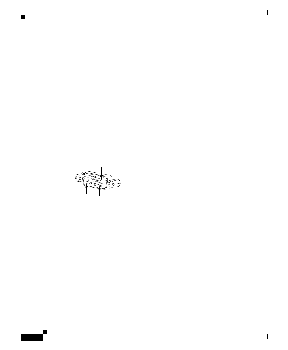
Configuring a Modem
Configuring a Modem
You must configure the modem before you can connect it to the GSS. You can
connect the modem to a terminal or a PC using a terminal emulation program,
such as Hyperterminal. If you connect the modem to the COM port on a PC, you
need the following cable and connectors:
• RJ-45-to-RJ-45 rolled cable
• RJ-45-to-DB-25 modem adapter
• DB-9-to-RJ-45 terminal adapter
Figure B-1 shows the pin number assignments for the 9-pin, male D-shell console
port connector on the back of the GSS. These pin number assignments conform to
the industry standard.
Figure B-1 Console Port Connector Pin Numbers
Appendix B Connecting a Modem to the GSS Console Port
1
5
6
9
119657
Table B-1 connector pinouts for the GSS console port.
B-2
Cisco Global Site Selector 4491 Hardware Installation Guide
78-16356-01
Page 83

Appendix B Connecting a Modem to the GSS Console Port
Table B-1 Console Port Connector Pinouts
Pin Signal I/O Definition
1 DCD I Data carrier detect
2 SIN I Serial input
3 SOUT O Serial output
4 DTR O Data terminal ready
5 GND N/A Signal ground
6 DSR I Data set ready
7 RTS O Request to send
8 CTS I Clear to send
9 RI I Ring indicator
Shell N/A N/A Chassis ground
You configure the modem by entering commands from the Attention (AT)
command set and, if applicable, setting the configuration switches on the modem.
Although the process to configure the modem may vary from one modem to
another, configure your modem so that its resulting behavior is as follows:
Configuring a Modem
78-16356-01
• Answers a call on the first ring
• Disables both hardware and software flow control mechanisms
• Ignores modem control signals DTR and RTS
• Suppresses echoing of command mode input
• Disables recognition of AT commands
Cisco Global Site Selector 4491 Hardware Installation Guide
B-3
Page 84
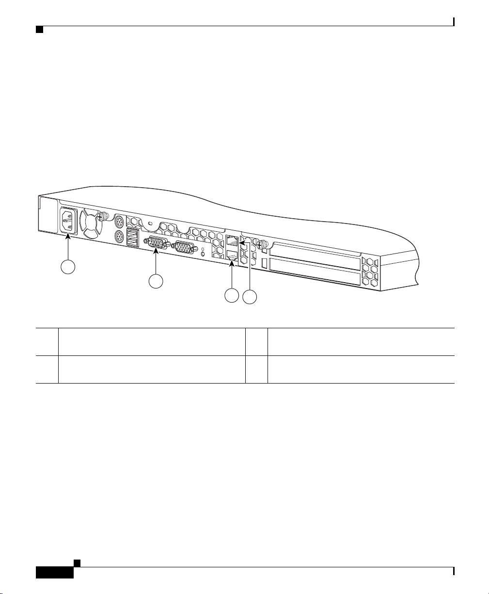
Appendix B Connecting a Modem to the GSS Console Port
Cabling a Modem to the GSS
Cabling a Modem to the GSS
After you configure the modem, perform the following steps to connect a modem
to the GSS:
1. Unplug the flat rolled RJ-45-to-RJ-45 cable from the terminal adapter on the
PC and connect the cable to the console port on the GSS (Figure B-2).
Figure B-2 Rear Panel Ports and Connectors
i
1
2
3
4
119605
1 AC power receptacle 3 RJ-45 Ethernet 1 connector with
10/100/1000-Mbit/s operation
2 Console/serial connector 4 RJ-45 Ethernet 0 connector with
10/100/1000-Mbit/s operation
Cisco Global Site Selector 4491 Hardware Installation Guide
B-4
78-16356-01
Page 85

Appendix B Connecting a Modem to the GSS Console Port
2. Ensure that the settings on the remote console match the GSS default settings
specified in Tab le B-2.
Table B-2 Console Port Default Settings
Parameters Default Settings
Baud 9600
Data Bits 8
Parity None
Stop Bits 1
Terminal Type VT100/ANSI
Flow Control None
Note When you remotely log in to the GSS through a modem, ensure that you log out
before disconnecting from the session. Use the exec-timeout timeout command to
set the maximum amount of time that the console session can be idle on the GSS
before it logs out. By default, the timeout is 150 minutes.
Cabling a Modem to the GSS
78-16356-01
Cisco Global Site Selector 4491 Hardware Installation Guide
B-5
Page 86

Cabling a Modem to the GSS
Appendix B Connecting a Modem to the GSS Console Port
B-6
Cisco Global Site Selector 4491 Hardware Installation Guide
78-16356-01
Page 87

INDEX
A
AC electrical specifications A-1
AC power 2-10
connecting to GSS 3-16
cord, connecting 3-16
line conditioners 5-8
power source interruptions 5-6
protection devices 5-7
receptacle 1-5, 3-15, B-4
site installation preparation 2-10
uninterruptible power supplies 5-8
altitude, guidelines 5-3
audience xiv
B
booting the GSS 4491 3-17
boot sequence 3-17
C
cabling
cables, connecting
Category 5e cable 1-8, 3-15
3-15
front panel functions 1-3
general precautions 2-6
rear panel functions 1-5
requirements 1-8, 3-15
site preparation guidelines 2-11
troubleshooting connections 4-2
cautions, description of xvii
CD-ROM drive 1-3
cleaning operating environment, guidelines 5-4
CLI
saving connection session
3-19
serial console connection, establishing 3-18
connections
cables
3-15
console port to modem B-1
power 3-16
troubleshooting 4-2
console port
connections
3-16
connector pinouts B-2
description 1-6
establishing connection 3-18
location 1-5, 3-15
modem, connecting B-1
operating settings 1-7
78-16356-01
Cisco Global Site Selector 4491 Hardware Installation Guide
IN-1
Page 88

Index
pinouts 1-7, B-3
corrosion, preventing damage 5-4
D
damage to product, reporting 3-2
documentation
conventions
xvii
related xvi
set xvi
dust, preventing damage 5-4
E
electrical specifications A-1
electricity, safety precautions 2-6
electromagnetic interference
See EMI
electrostatic discharge, protecting against
5-4
EMI, preventing effects of 5-5
environment, maintaining 5-1
environmental
site requirements
specifications A-2
ESD, preventing damage 5-4
Ethernet interfaces
cabling requirements
Category 5 UTP cable 3-15
2-9
1-8, 3-15
2-7,
connector pinout 1-8
description 1-8
Ethernet 0 Activity LED 1-4, 3-20
Ethernet 0 connector 1-5
Ethernet 0 Link LED 1-4, 3-20
Ethernet 1 Activity LED 1-4, 3-20
Ethernet 1 connector 1-5
Ethernet 1 Link LED 1-4, 3-20
Ethernet controller 1-8
specifications A-3
F
four-post rack mount kit
attaching chassis to rack
3-11
components 3-5
installation instructions 3-4
telescopic rails, attaching 3-6
front panel
features
1-3
illustration 1-3
LED indicators 1-4, 3-19
overview 1-3
G
GSS 4491
booting
boot sequence 3-17
3-17
IN-2
Cisco Global Site Selector 4491 Hardware Installation Guide
78-16356-01
Page 89

Index
connections 1-5
front panel features 1-3
general precautions 2-6
hardware features 1-2
installing 3-3
LED indicators 1-4
maintaining 5-1
monitoring LED operating status 3-19
overview 1-1
ports and connectors 1-6
power button 1-3
rear panel features 1-5
removing from network 3-21
removing or replacing 3-20
reporting damage 3-2
safety warnings and cautions 2-2
shipment contents 3-2
site environment, maintaining 5-1
site requirements 2-8
technical specifications A-1
troubleshooting hardware issues 4-1
unpacking and inspecting 3-2
workbench or tabletop, installing 3-14
H
hard drive
indicator
magnetism effects 5-6
1-4, 3-20
hardware
features
1-2
troubleshooting 4-1
humidity guidelines 5-3
HyperTerminal
launching
3-18
saving session 3-19
I
installation
choosing a site
creating a safe environment 2-10
general precautions 2-6
installing in a rack 3-4
network, setting up 2-12
precautions for rack-mounting 2-11
preparing for
LAN options, precautions for
modems, precautions for 2-12
telecommunications, precautions for 2-12
required tools and equipment 2-12
site preparation 2-8
site requirements 2-8
tabletop 3-14
tools and equipment required 2-12
two-post rack bracket instructions 3-12
unpacking and inspecting 3-2
workbench 3-14
2-9
2-12
78-16356-01
Cisco Global Site Selector 4491 Hardware Installation Guide
IN-3
Page 90

Index
L
LAN
options, precautions for
2-12
precautions 2-12
LED indicators
Ethernet 0 Activity
1-4, 3-20
Ethernet 0 Link 1-4, 3-20
Ethernet 1 Activity 1-4, 3-20
Ethernet 1 Link 1-4, 3-20
front panel 3-19
hard drive activity 1-4, 3-20
monitoring GSS operating status 3-19
power 1-4, 3-20
power spike 1-4, 3-20
line conditioners, using 5-8
M
P
physically removing a GSS 4491 from a
network
physical specifications A-3
port connectors 1-6
port specifications A-3
power
AC power receptacle
connecting to system 3-16
power indicator LED 1-4, 3-20
power source interruptions, preventing
damage
power spike indicator LED 1-4, 3-20
power button 1-3
power protection devices 5-7
power source interruptions 5-6
power supplies, using uninterruptible 5-8
3-21
1-5
5-6
magnetism, preventing effects of 5-6
modem
connecting to console port
B-1
precautions 2-12
N
network, physically removing a GSS 4491 3-21
Cisco Global Site Selector 4491 Hardware Installation Guide
IN-4
R
rack mounting
four-post rack
identifying GSS 4491 by System ID
button
installation considerations 3-4
precautions 2-11
procedure 3-4
two-post rack bracket 3-12
radio frequency interference. See RFI
3-4
1-3, 1-5
78-16356-01
Page 91

Index
rear panel
connections
1-5
features 1-5
RFI, preventing effects of 5-5
S
safety
creating a safe environment
electrostatic discharge 2-7
general precautions 2-6
important safety instructions 2-3
installation 2-2
precautions with electricity 2-6
preventing EMI 2-8
safe environment, creating 2-10
warnings xviii
warnings and cautions 2-2
with electricity 2-6
serial port
connection
3-18
description 1-6
location 1-5, 3-15, B-4
pinouts 1-7, B-3
server load balancers
Cisco Content Services Switch
Cisco Content Switching Module (Catalyst
6500 series)
1-1
Cisco IOS SLB 1-1
Cisco LocalDirector 1-1
2-10
1-1
overview 1-2
site
environment, maintenance factors
5-1
preparation 2-8
requirements 2-8
specifications
electrical
A-1
environmental A-2
GSS 4491 A-1
physical A-3
port A-3
surge protectors, using 5-7
System ID button, identifying GSS 4491
1-3, 1-5
by
T
tabletop installation procedure 3-14
telecommunications, precautions 2-12
temperature guidelines 5-2
troubleshooting
basic checks
connections 4-2
switches 4-2
troubleshooting system hardware 4-1
two-post rack bracket, attaching 3-12
4-1
78-16356-01
Cisco Global Site Selector 4491 Hardware Installation Guide
IN-5
Page 92

Index
U
uninterruptible power supplies, using 5-8
W
warnings
regarding
batteries and explosion danger
chassis, opening 2-3
chassis, working on 2-3
disposal of unit 2-5
explosion 2-5
faceplates and cover panels, removing 2-4
failure to ground equipment 2-4
ground conductor, defeating 2-3, 2-10
installation area 2-9
instructions, reading 2-5
jewelry 2-4
lightning activity 2-4, 3-15
On/Off switch 2-5
power cords, more than one 2-4
rack-mounting equipment 2-11
safety cover 2-3
short circuits 2-4, 2-10
translations of 2-2
workbench installation procedure 3-14
2-5
IN-6
Cisco Global Site Selector 4491 Hardware Installation Guide
78-16356-01
 Loading...