

Page 1

CHA PT ER
3
Managing ITP Networks Using SGM
This chapter provides details on using SGM to discover and manage your ITP
networks. It includes the following sections:
• Becoming the Root User (Solaris Only), page 3-2
• Configuring SNMP, page 3-2
• Discovering the Network, page 3-6
• Configuring Seed Files, page 3-20
• Working with Views, page 3-26
• Working with Linksets, page 3-37
• Working with Nodes, page 3-91
• Working with Signaling Points, page 3-136
• Working with Links, page 3-170
• Working with Events, page 3-235
• Viewing the Topology of the Network, page 3-259
78-15589-01
• Viewing Server Status Information, page 3-274
• Finding Information in a Window, page 3-278
• Resizing, Sorting, and Hiding Table Columns, page 3-279
• Viewing Online Help, page 3-280
• Editing an ITP Route Table File, page 3-281
• Editing a Global Title Translation Table, page 3-290
• Working with SGM Statistics Reports, page 3-334
Cisco Signaling Gateway Manager User Guide
3-1
Page 2

Chapter 3 Managing ITP Networks Using SGM
Becoming the Root User (Solaris Only)
• Printing SGM Windows, page 3-398
• Connecting to a New Server, page 3-399
• Integrating SGM with Other Products, page 3-401
• Using the Windows Start Menu, page 3-403
Becoming the Root User (Solaris Only)
Some SGM procedures require you to be logged in as the root user.
Caution As the root user, you can adversely affect your operating environment if you are
unaware of the effects of the commands you use. If you are a relatively
inexperienced UNIX user, limit your activities as the root user to the tasks
described in this manual.
If you are not logged in, log in as the root user:
> login: root
> Password: root-password
If you are already logged in, but not as the root user, use the su command to
change your login to root:
# su
# Password:
Configuring SNMP
If SGM User-Based Access is disabled, or if it is enabled and you are a Network
Administrator or System Administrator, SGM enables you to view and change
some SNMP settings. (For more information about user authorization levels in
SGM, see the “Configuring SGM User Authentication Levels (Solaris Only)”
section on page 4-6.)
Cisco Signaling Gateway Manager User Guide
3-2
root-password
78-15589-01
Page 3
Chapter 3 Managing ITP Networks Using SGM
Note If you want to change SNMP settings, do so before running Discovery.
To change SNMP settings in SGM:
Step 1 Start the SGM client, as described in the “Starting SGM” section on page 2-2.
Step 2 Select Edit > SNMP Configuration from the SGM Main Menu. (If you have
implemented SGM User-Based Access, this option is available to users with
authentication level Network Administrator [Level 4] and higher.) SGM displays
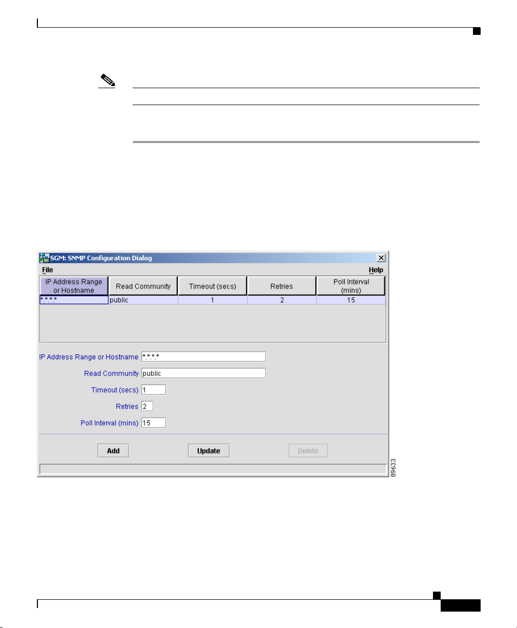
the SNMP Configuration Dialog (Figure 3-1).
Figure 3-1 SNMP Configuration Dialog
Configuring SNMP
78-15589-01
The SNMP settings table displays SNMP information for nodes in SGM.
Step 3 (Optional) To delete a node, select it and click Delete.
Cisco Signaling Gateway Manager User Guide
3-3
Page 4

Configuring SNMP
Step 4 (Optional) To change the IP address or DNS name of a node, select the node and
Step 5 (Optional) Nodes use SNMP community names for read access to the information
Chapter 3 Managing ITP Networks Using SGM
enter the new address or name in the IP Address Range or Hostname field.
• IP addresses use the format x.x.x.x, where each x has one of the following
values:
–
An integer in the range 0 through 255.
–
A range of integers separated by a dash (-), such as 10-60.
–
An asterisk (*), which is equivalent to specifying 0-255.
• Unlike IP addresses, you cannot specify a range of node names or use
wildcards in node names. Each node name corresponds to a single node in the
network.
The default value for this field is the IP address *.*.*.*, which SGM uses for all
nodes not covered by other IP address ranges or names.
Click Update to apply the new IP address to the selected node.
maintained by the SNMP agent on the ITP. To change the SNMP community name
for a node, select the node and enter the new name in the Read Community field.
This name must match the name used by the node. The default name is public.
Click Update to apply the new SNMP community name to the selected node.
For information about exporting SNMP community names from CiscoWorks2000
Resource Manager Essentials (RME), see the “Importing SNMP Community
Names from CiscoWorks2000 (Solaris Only)” section on page 5-2.
3-4
Step 6 (Optional) If you determine that SGM waits too long for a response from a node,
or does not wait long enough, you can change the timeout value. To change the
time, in seconds, that SGM waits for a response from a node, select the node and
enter the new timeout value in the Timeout (secs) field. The valid range is 1 to 60
seconds. The default value is 1 second.
Click Update to apply the new timeout to the selected node.
Step 7 (Optional) If you determine that SGM retries a node too many times, or not
enough times, you can change the number of retries. To change the number of
times SGM attempts to connect to a node, select the node and enter the new
number in the Retries field. The valid range is 0 to 99. The default value is
2retries.
Click Update to apply the new retries value to the selected node.
Cisco Signaling Gateway Manager User Guide
78-15589-01
Page 5

Chapter 3 Managing ITP Networks Using SGM
Step 8 (Optional) If you determine that SGM polls a node too often, or not often enough,
you can change the poll interval. To change the time, in minutes, between polls
for a node, select the node and enter the new interval in the Poll Interval (mins)
field. The valid range is 5 to 1440. The default value is 15 minutes.
Click Update to apply the new poll interval to the selected node.
Step 9 (Optional) To add a new node or range of nodes, enter the SNMP information in
the appropriate fields and click Add. The new SNMP settings are added to the
SGM database.
When you are satisfied with all of your changes to the SNMP settings, select the
File > Save menu option. SGM saves the changes, updates the SNMP information
on the SGM server in real time, and closes the SNMP Configuration Dialog.
Note If another user modifies and saves the SNMP configuration before you
save your changes, SGM asks if you want to overwrite that user’s
changes. If you choose to do so, the other user’s changes are overwritten
and lost. If you choose not to do so, your changes are lost.
Configuring SNMP
78-15589-01
For more information about SNMP, refer to “Configuring SNMP Support” in the
Cisco IOS Release 12.2 Configuration Fundamentals Configuration Guide,
Part 3, Cisco IOS System Management.
SGM also provides the following SNMP-related commands:
• To set a new default SNMP read community name, use the sgm snmpcomm
command.
• To change the file used for SNMP parameters, such as community names,
timeouts, and retries, use the sgm snmpconf command.
• To query a host using SNMP GetRequests, use the sgm snmpget command.
• To query a host using SNMP GetNextRequests, use the sgm snmpnext
command.
• To query a host, using SNMP GetNextRequests to “walk” through the MIB,
use the sgm snmpwalk command.
For more information on the use of these commands, see the “SGM Commands
and Descriptions” section on page B-2.
Cisco Signaling Gateway Manager User Guide
3-5
Page 6

Discovering the Network
Discovering the Network
SGM uses a Discovery process to populate the SGM database, discovering the
nodes, signaling points, linksets, and links in your network.
You can run Discovery if SGM User-Based Access is disabled, or if it is enabled
and you are a Network Administrator or System Administrator. (For more
information about user authorization levels in SGM, see the “Configuring SGM
User Authentication Levels (Solaris Only)” section on page 4-6.)
Related Topics:
• Backing Up or Restoring SGM Files (Solaris Only), page 5-47
• Configuring Seed Files, page 3-20
• Investigating Data Problems, page 6-2
• Verifying Discovery, page 6-1
Chapter 3 Managing ITP Networks Using SGM
3-6
Cisco Signaling Gateway Manager User Guide
78-15589-01
Page 7
Chapter 3 Managing ITP Networks Using SGM
To discover the network in SGM:
Step 1 Start the SGM client, as described in the “Starting SGM” section on page 2-2.
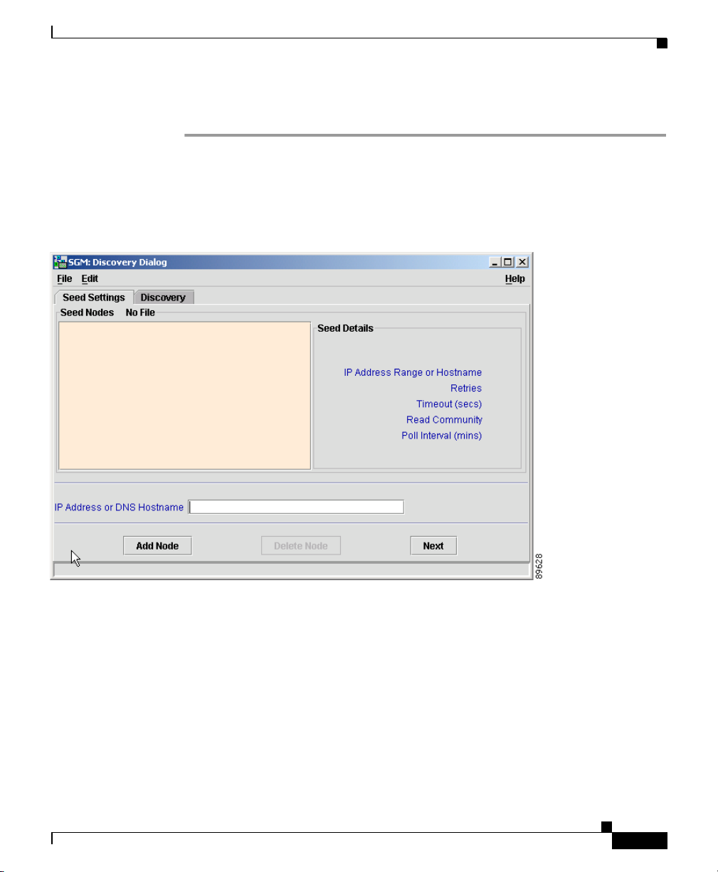
Step 2 Select Edit > Network Discovery from the SGM Main Menu. SGM displays the
Discovery Dialog (Figure 3-2).
Figure 3-2 Discovery Dialog
Discovering the Network
78-15589-01
If you start the SGM client and the SGM database is empty (including the very
first time you start the SGM client), SGM automatically opens the Discovery
Dialog so you can run Discovery and populate the database.
Step 3 Select the Seed Settings tab, if it is not already selected. SGM displays the Seed
Settings panel, which enables you to create, save, load, and delete SGM seed files.
Seed files are lists of seed nodes, which SGM uses to discover the nodes, signaling
points, linksets, and links in your network.
Cisco Signaling Gateway Manager User Guide
3-7
Page 8
Discovering the Network
Step 4 Load one or more seed nodes, using one of the following procedures:
Chapter 3 Managing ITP Networks Using SGM
• Enter the name or IP address of a seed node in the IP Address or DNS
Hostname field, and click Add Node.
SGM displays details of the SNMP settings for the seed nodes in the right
pane of the window.
Continue adding seed nodes until you are certain that SGM will be able to
discover the entire network.
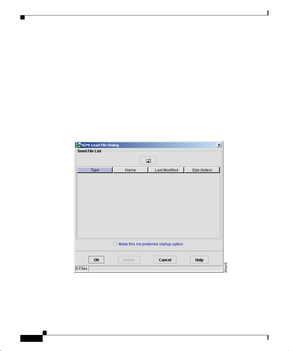
• If you have already created and saved a seed file, select File > Load Seeds
from the Discovery Dialog menu. SGM displays the Load File Dialog: Seed
File List dialog (Figure 3-3).
Figure 3-3 Load File Dialog: Seed File List Dialog
3-8
The Load File Dialog: Seed File List dialog contains the following fields:
–
Type—Icon indicating whether the item in the table is a file or a folder.
–
Name—Name of the seed file or folder.
–
Last Modified—Date and time the seed file or folder was last modified.
Cisco Signaling Gateway Manager User Guide
78-15589-01
Page 9

Chapter 3 Managing ITP Networks Using SGM
–
Size (bytes)—Size of the seed file or folder, in bytes.
–
Make this my preferred start option—Specifies whether the selected
seed file is to be loaded automatically whenever this SGM client is
started or the Discovery Dialog is opened. By default, this checkbox is
cleared for all seed files. That is, no seed file is loaded automatically
when the SGM client is started or the Discovery Dialog is opened.
–
Number of Files—Total number of seed files and folders (displayed in
bottom left corner).
To load a seed file, select the seed file in the list and click OK.
SGM closes the Load File Dialog: Seed File List dialog, loads the seed file,
and returns to the Discovery Dialog. SGM lists all of the seed nodes in the
seed file in the left pane of the window, and displays details of the SNMP
settings for the seed nodes in the right pane.
To close the Load File Dialog: Seed File List dialog without loading a seed
file, click Cancel.
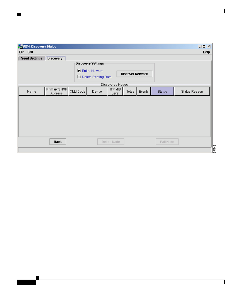
Step 5 Select the Discovery tab, or click Next. SGM displays the Discovery panel
(Figure 3-4), which enables you to discover the nodes, signaling points, linksets,
and links in your network. (If you enter a seed node IP address or name in the IP
Address or DNS Hostname field, then click Next, SGM automatically adds the
seed node before displaying the Discovery panel.)
Discovering the Network
78-15589-01
Cisco Signaling Gateway Manager User Guide
3-9
Page 10
Discovering the Network
Figure 3-4 Discovery Panel
Chapter 3 Managing ITP Networks Using SGM
3-10
Step 6
(Optional) Specify the extent of the network discovery.
• To discover the entire network, select the Entire Network checkbox. This is
called recursive discovery, and it is the default setting. Select this checkbox
when you run Discovery for the very first time.
With this checkbox selected, SGM discovers all seed nodes and attempts to
manage them; then attempts to discover and manage all ITP nodes that are
adjacent to those seed nodes (unless the nodes are connected by serial links
only); then attempts to discover and manage all ITP nodes that are adjacent
to those nodes; and so on, until SGM has discovered the entire network.
• To rediscover only seed nodes, clear the Entire Network checkbox. This is
called nonrecursive discovery.
With this checkbox cleared, SGM discovers all seed nodes and attempts to
manage them, then labels all nodes that are adjacent to those seed nodes
Unmanaged.
Cisco Signaling Gateway Manager User Guide
78-15589-01
Page 11

Chapter 3 Managing ITP Networks Using SGM
If you run Discovery with Entire Network cleared, then you run Discovery with
Entire Network selected, any Unmanaged nodes in the first Discovery are not
rediscovered by the second Discovery.
To recover from this situation and generate a new, complete, and reliable SGM
database, you must perform one of the following procedures:
a. Run Discovery again, with both Entire Network and Delete Existing Data
selected.
b. Change the Unmanaged nodes to managed status. See the “Unmanaging and
Managing a Node” section on page 3-133 for more information.
c. Poll the nodes that were Unmanaged in the first Discovery. See the “Polling
a Node” section on page 3-134 for more information.
Step 7 (Optional) Specify whether SGM is to keep or delete the existing database when
discovering the network:
• To keep all existing network data in the SGM database before rediscovering
the network, clear the Delete Existing Data checkbox. This is the default
setting. Clear this checkbox when you run Discovery for the very first time.
• To delete all existing network data from the SGM database before
rediscovering the network, select the Delete Existing Data checkbox.
Choose this option if you know that network elements have been deleted from
your network since the last Discovery.
Discovering the Network
78-15589-01
Note If you discover the network with Delete Existing Data selected, SGM
stops any real-time polls that are running and issues appropriate
messages.
Cisco Signaling Gateway Manager User Guide
3-11
Page 12

Discovering the Network
Step 8 Click Discover Network to begin Discovery.
Step 9 (Optional) To stop the Discovery process at any time, click Stop Discovery. For
Chapter 3 Managing ITP Networks Using SGM
When Discovery begins:
• The Discover Network button is grayed-out.
• The “Discovery In Progress” message is displayed at the bottom of the
Discovery Dialog.
• The “Discovery In Progress” message is displayed in the title bar of all SGM
client windows.
Discovery progresses in bursts. You might see a number of updates, followed by
a pause, followed by more updates. The information displayed in SGM windows
is not fully updated until Discovery is complete.
By default, Discovery times out after 600 seconds (10 minutes). To change the
Discovery timeout, change the value of the DISCOVERY_TIMELIMIT entry in
the Server.properties file:
• If you installed SGM in the default directory, /opt, then the location of the
Server.properties file is /opt/CSCOsgm/properties/Server.properties.
• If you installed SGM in a different directory, then the Server.properties file is
located in that directory.
Because SGM is an asynchronous system, with the SGM server contacting clients
one at a time, and because clients might run at different speeds, the information
displayed by SGM clients during Discovery might not always be synchronized.
example, if you click Discover Network, then you realize that you loaded a seed
node that you did not intend to load, you can click Stop Discovery to stop the
Discovery process.
3-12
Note If you stop the Discovery process, the information in the SGM database
is incomplete and unreliable. To generate a new, complete, and reliable
SGM database, you must run Discovery again, with Delete Existing
Data selected.
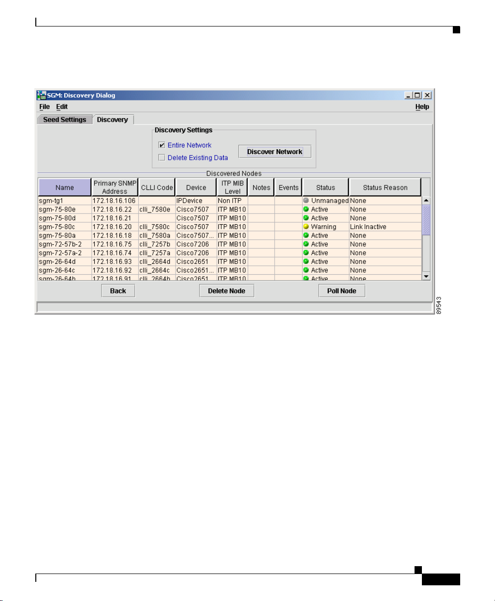
Step 10 When the “Discovery In Progress” message disappears, Discovery is complete.
The Discovered Nodes section of the Discovery panel (Figure 3-5) lists all nodes
that were discovered by SGM. By default, this table is sorted by Status.
Cisco Signaling Gateway Manager User Guide
78-15589-01
Page 13
Chapter 3 Managing ITP Networks Using SGM
Figure 3-5 Discovery Panel with Discovered Nodes
Discovering the Network
78-15589-01
By default, SGM displays all of the columns in the Discovered Nodes section
except Internal ID, ITP Uptime, Reboot Reason, and Last Status Change. To
display these columns, or to hide other columns, see the procedures in the
“Modifying Node Table Column Settings” section on page 5-16.
To see mouse over help popup for each column in the table, place the cursor over
a column header.
If a cell is too small to show all of its data, place the cursor over the cell to see the
full data in a mouse over help popup.
You can resize each column, or sort the table based on the information in one of
the columns. See the “Resizing, Sorting, and Hiding Table Columns” section on
page 3-279 for more details.
Cisco Signaling Gateway Manager User Guide
3-13
Page 14

Discovering the Network
Chapter 3 Managing ITP Networks Using SGM
The Discovered Nodes section displays the following information for each
discovered node:
• Internal ID—Internal ID of the event. The internal ID is a unique ID for
every event, link, linkset, signaling point, and node, assigned by SGM for its
own internal use. It can also be useful when the TAC is debugging problems.
• Name—Name or IP address of the discovered node.
• Primary SNMP Address—IP address of the node, used by SNMP to poll the
node. (There might be other IP addresses on the node that are not the primary
SNMP address.)
• CLLI Code—COMMON LANGUAGE Location Identification Code for the
node. A CLLI code is a standardized 11-character identifier that uniquely
identifies the geographic location of the node. If the node has no CLLI code
configured, this field is blank.
• Device Type—Device type of the node. Possible values are:
–
Cisco2650—Cisco 2650 series router
–
Cisco2650XM—Cisco 2650XM series router
–
Cisco2651—Cisco 2651 series router
–
Cisco2651XM—Cisco 2651XM series router
–
Cisco7204—Cisco 7204 series router
3-14
–
Cisco7204VXR—Cisco 7204VXR series router
–
Cisco7206—Cisco 7206 series router
–
Cisco7206VXR—Cisco 7206VXR series router
–
Cisco7507—Cisco 7507 series router
–
Cisco7507mx—Cisco 7507mx series router
–
Cisco7507z—Cisco 7507z series router
–
Cisco7513—Cisco 7513 series router
–
Cisco7513mx—Cisco 7513mx series router
–
Cisco7513z—Cisco 7513z series router
–
IPDevice—IP device, other than those listed above. You can assign this
icon to an unknown node if you know that it is an IP device.
–
Unknown—SGM is unable to determine the device type.
Cisco Signaling Gateway Manager User Guide
78-15589-01
Page 15

Chapter 3 Managing ITP Networks Using SGM
• ITP MIB Level—MIB conformance level used by the ITP, such as ITP MB5.
• ITP Uptime—Time the ITP has been up, in weeks, days, hours, minutes, and
seconds.
• Reboot Reason—Reason for the last reboot of the ITP.
• Notes—Indicates whether there is a note associated with the node.
• Events—Indicates whether there is a recent event associated with the node.
During Discovery, SGM might flag most nodes with an event icon. If the
event icons are too distracting, select Edit > Clear All Events from the SGM
Main Menu to remove them.
• Last Status Change—Date and time that the status of the node last changed.
• Status—Current status of the node. Possible values are:
–
Active (green ball)—The node is currently fully functional.
–
Discovering (gray ball)—The node is being discovered, and SNMP
queries have been sent to the device.
–
Polling (gray ball)—The node is being polled.
–
Unknown (red ball)—The node failed to respond to an SNMP request.
SGM sets all associated signaling points, linksets, and links to
Unknown.
–
Unmanaged (gray ball)—One of the following situations exists:
– The node is known indirectly by SGM. In other words, SGM knows the
device exists but there is no known SNMP stack on the device for SGM
to query.
Discovering the Network
78-15589-01
– An SGM user has set the node to Unmanaged status, to prevent SGM
from polling the node.
If the associated signaling points are referenced via linksets to other
signaling points, SGM automatically sets all associated signaling points
to Unmanaged, and deletes all associated linksets and links, as well as
all linksets and links that reference the node as an adjacent node.
If the associated signaling points are not referenced to other signaling
points, SGM automatically deletes the signaling points, all associated
linksets and links, and all linksets and links that reference the node as an
adjacent node.
Cisco Signaling Gateway Manager User Guide
3-15
Page 16

Discovering the Network
Chapter 3 Managing ITP Networks Using SGM
–
Waiting (gray ball)—The node is in the Discovery queue but is not
currently being discovered.
–
Warning (yellow ball)—The node is active, but one or more associated
signaling points, linksets, or links is in Failed, Unavailable, Unknown,
or Warning status and is not Ignored.
• Status Reason—Reason for the current status of the node. Possible values
are:
–
None
–
SGM Restart
–
Unsupported Configuration
–
Unconfigured
–
SNMP Timeout
–
Device is unreachable, possibly wrong community string
–
Not ITP Device
–
Not Configured for ITP
–
MIB Data Error
–
SNMP Exception
–
SignalingPoint Inactive
3-16
–
Linkset Inactive
–
Link Congested
–
Link Send Utilization Threshold Exceeded
–
Link Receive Utilization Threshold Exceeded
–
Link Local Interface Inactive
–
Link Remote Interface Inactive
–
Link Inactive
If the cell is too small to show all of the status reason, place the cursor over
the cell to see the full status reason in a mouse over help popup.
The status reasons are listed in order of decreasing magnitude. If two or more
reasons apply, the reason of greatest magnitude is displayed.
Cisco Signaling Gateway Manager User Guide
78-15589-01
Page 17

Chapter 3 Managing ITP Networks Using SGM
If the status reason is Unsupported Configuration, correct the configuration
and enter the sgm cleandiscover command to delete all current network data
and begin a clean discovery of the ITP network. If the status reason is still
Unsupported Configuration, enter the sgm clean command to restore the
SGM server to a “clean” state, such as would exist after a new installation of
SGM. For more information on the use of these commands, see the “SGM
Commands and Descriptions” section on page B-2.
The “Viewing Detailed Information for a Link” section on page 3-175
displays additional information about the causes of link failures.
The “Viewing Detailed Information for a Linkset” section on page 3-42
displays additional information about the causes of linkset failures.
All discovered nodes are placed in a DEFAULT configuration view, which is
stored on the SGM server and shared by all SGM clients. Initially, all clients use
the DEFAULT view. Clients can then create their own views, which are subsets of
the DEFAULT view, to meet their individual needs. However, the DEFAULT view
stored on the SGM server cannot be modified by the clients. It is always available,
for users who need to view the entire network.
All other SGM windows (Node, Signaling Point, Linkset, Topology, and so on)
are also populated with the newly discovered network data.
Discovering the Network
78-15589-01
Step 11 (Optional) To delete a node or nodes from the Discovery database, select the
nodes and click Delete Node. SGM deletes the nodes without asking for
confirmation.
Step 12 (Optional) Examine the Discovered Nodes table to verify that SGM discovered all
of the nodes in the network. If you suspect that SGM did not discover all of the
nodes, see the “Verifying Discovery” section on page 6-1 for troubleshooting
information. You might need to add more seed nodes and run Discovery again.
Step 13 When you are satisfied that SGM discovered all of the nodes in the network, save
the list of seed nodes in a seed file, using one of the following procedures:
• To save the changes you have made to the seed file without changing the name
of the file, select File > Save from the Discovery Dialog menu.
• To save the changes you have made to the seed file with a new name, select
File > Save As from the Discovery Dialog menu. SGM displays the Save File
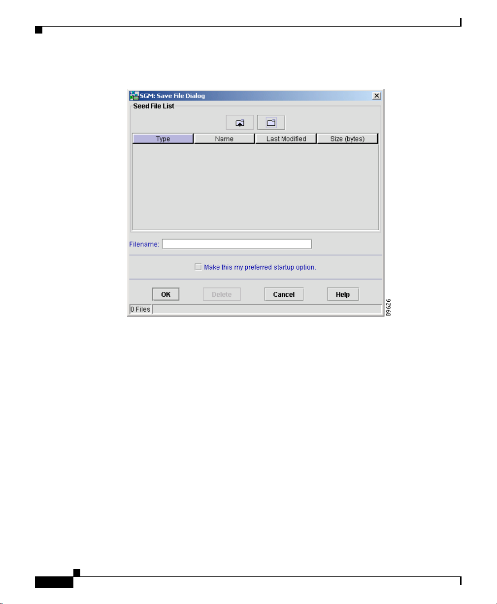
Dialog: Seed File List dialog (Figure 3-6).
Cisco Signaling Gateway Manager User Guide
3-17
Page 18
Discovering the Network
Chapter 3 Managing ITP Networks Using SGM
Figure 3-6 Save File Dialog: Seed File List Dialog
3-18
The Save File Dialog: Seed File List dialog contains the following fields:
• Type—Icon indicating whether the item in the table is a file or a folder.
• Name—Name of the seed file or folder.
• Last Modified—Date and time the seed file or folder was last modified.
• Size (bytes)—Size of the seed file or folder, in bytes.
• Filename—Name by which you want to save the seed file.
If you create a new seed file name, you can use any letters, numbers, or
characters in the name that are allowed by your operating system. However,
if you include any spaces in the new name, SGM converts those spaces to
dashes. For example, SGM saves file “a b c” as “a-b-c”.
Cisco Signaling Gateway Manager User Guide
78-15589-01
Page 19

Chapter 3 Managing ITP Networks Using SGM
• Make this my preferred start option—Specifies whether the selected seed
file is to be loaded automatically whenever this SGM client is started or the
Discovery Dialog is opened. By default, this checkbox is cleared for all seed
files. That is, no seed file is loaded automatically when the SGM client is
started or the Discovery Dialog is opened.
• Number of Files—Total number of seed files and folders (displayed in
bottom left corner).
To save the seed file with a new name, use one of the following procedures:
• To save the file with a completely new name, enter the new name and click
OK.
• To save the file with an existing name, overwriting an old seed file, select the
name in the list and click OK.
SGM saves the seed file with the new name, closes the Save File Dialog: Seed File
List dialog, and returns to the Discovery Dialog.
Note If another user modifies and saves the seed file before you save your
changes, SGM asks if you want to overwrite that user’s changes. If you
choose to do so, the other user’s changes are overwritten and lost. If you
choose not to do so, your changes are lost, unless you save the seed file to
a different filename.
Discovering the Network
78-15589-01
SGM stores the seed file in the seed file directory on the SGM server:
• If you installed SGM in the default directory, /opt, then the SGM seed file
directory is /opt/CSCOsgm/seeds.
• If you installed SGM in a different directory, then the SGM seed file directory
is located in that directory.
To delete a seed file from the seed file list, select a file and click Delete. SGM
issues an informational message containing the name and location of the deleted
file.
To save any changes you made to the list of files, click OK. SGM saves the
changes and closes the Save File Dialog: Seed File List dialog.
To close the Save File Dialog: Seed File List dialog without saving the seed file
or saving any changes to the seed file list, click Cancel.
Cisco Signaling Gateway Manager User Guide
3-19
Page 20

Configuring Seed Files
You can run Discovery multiple times to attempt to discover additional nodes
based on the IP address defined in the Stream Control Transmission Protocol
(SCTP) linksets. If you are using a separate management VLAN to manage your
nodes, but private or unreachable IP addresses for your SCTP connectivity, clear
the Entire Network checkbox in the Discovery Dialog. Otherwise, Discovery
attempts to reach those nodes continuously. Instead, enter all nodes to be
discovered directly into the seed list and do a nonrecursive Discovery.
Configuring Seed Files
SGM enables you to create, save, load, and delete SGM seed files.
This section includes the following information:
• Creating a New Seed File, page 3-20
• Modifying an Existing Seed File, page 3-22
• Creating and Modifying Seed Files Using a Text Editor, page 3-24
Related Topics:
• Discovering the Network, page 3-6
Chapter 3 Managing ITP Networks Using SGM
Creating a New Seed File
To create a new seed file in SGM:
Step 1 Select Edit > Network Discovery from the SGM Main Menu. SGM displays the
Discovery Dialog (Figure 3-2).
Step 2 Select the Seed Settings tab, if it is not already selected. SGM displays the Seed
Settings panel.
Step 3 Enter the name or IP address of a seed node in the IP Address or DNS Hostname
field, and click Add Node. SGM displays details of the SNMP settings for the
seed node in the right pane of the window.
Continue to add as many seed nodes as necessary.
Cisco Signaling Gateway Manager User Guide
3-20
78-15589-01
Page 21

Chapter 3 Managing ITP Networks Using SGM
Step 4 When you are ready to save the list of seed nodes in a new seed file, select File >
Save As from the Discovery Dialog menu. SGM displays the Save File Dialog:
Seed File List dialog (Figure 3-6).
The Save File Dialog: Seed File List dialog contains the following fields:
• Type—Icon indicating whether the item in the table is a file or a folder.
• Name—Name of the seed file or folder.
• Last Modified—Date and time the seed file or folder was last modified.
• Size (bytes)—Size of the seed file or folder, in bytes.
• Filename—Name by which you want to save the seed file. You can use any
letters, numbers, or characters in the name that are allowed by your operating
system. However, if you include any spaces in the new name, SGM converts
those spaces to dashes. For example, SGM saves file “a b c” as “a-b-c”.
• Make this my preferred start option—Specifies whether the selected seed
file is to be loaded automatically whenever this SGM client is started or the
Discovery Dialog is opened. By default, this checkbox is cleared for all seed
files. That is, no seed file is loaded automatically when the SGM client is
started or the Discovery Dialog is opened.
Configuring Seed Files
78-15589-01
• Number of Files—Total number of seed files and folders (displayed in
bottom left corner).
Enter the new name and click OK. SGM saves the seed file with the new name,
closes the Save File Dialog: Seed File List dialog, and returns to the Discovery
Dialog.
SGM stores the new seed file in the seed file directory on the SGM server:
• If you installed SGM in the default directory, /opt, then the SGM seed file
directory is /opt/CSCOsgm/seeds.
• If you installed SGM in a different directory, then the SGM seed file directory
is located in that directory.
Cisco Signaling Gateway Manager User Guide
3-21
Page 22

Configuring Seed Files
Modifying an Existing Seed File
To modify an existing seed file in SGM:
Step 1 Select Edit > Network Discovery from the SGM Main Menu. SGM displays the
Discovery Dialog (Figure 3-2).
Step 2 Select the Seed Settings tab, if it is not already selected. SGM displays the Seed
Settings panel.
Step 3 Select File > Load Seeds from the Discovery Dialog menu. SGM displays the
Load File Dialog: Seed File List dialog (Figure 3-3).
The Load File Dialog: Seed File List dialog contains the following fields:
• Type—Icon indicating whether the item in the table is a file or a folder.
• Name—Name of the seed file or folder.
• Last Modified—Date and time the seed file or folder was last modified.
• Size (bytes)—Size of the seed file or folder, in bytes.
• Make this my preferred start option—Specifies whether the selected seed
file is to be loaded automatically whenever this SGM client is started or the
Discovery Dialog is opened. By default, this checkbox is cleared for all seed
files. That is, no seed file is loaded automatically when the SGM client is
started or the Discovery Dialog is opened.
• Number of Files—Total number of seed files and folders (displayed in
bottom left corner).
Chapter 3 Managing ITP Networks Using SGM
3-22
To load a seed file, select the seed file in the list and click OK.
SGM closes the Load File Dialog: Seed File List dialog, loads the seed file, and
returns to the Discovery Dialog. SGM lists all of the seed nodes in the seed file in
the left pane of the window, and displays details of the SNMP settings for the seed
nodes in the right pane.
To close the Load File Dialog: Seed File List dialog without loading a seed file,
click Cancel.
Step 4 (Optional) To add another seed node to the seed file, enter the name or IP address
of the seed node in the IP Address or DNS Hostname field, and click Add Node.
Step 5 (Optional) To delete a seed node from the seed file, select the seed node and click
Delete Node.
Cisco Signaling Gateway Manager User Guide
78-15589-01
Page 23

Chapter 3 Managing ITP Networks Using SGM
Step 6 When you are ready to save the modified seed file, use one of the following
procedures:
• To save the changes you have made to the seed file without changing the name
of the file, select File > Save from the Discovery Dialog menu.
• To save the changes you have made to the seed file with a new name, select
File > Save As from the Discovery Dialog menu. SGM displays the Save File
Dialog: Seed File List dialog (Figure 3-6).
The Save File Dialog: Seed File List dialog contains the following fields:
• Type—Icon indicating whether the item in the table is a file or a folder.
• Name—Name of the seed file or folder.
• Last Modified—Date and time the seed file or folder was last modified.
• Size (bytes)—Size of the seed file or folder, in bytes.
• Filename—Name by which you want to save the seed file.
If you create a new seed file name, you can use any letters, numbers, or
characters in the name that are allowed by your operating system. However,
if you include any spaces in the new name, SGM converts those spaces to
dashes. For example, SGM saves file “a b c” as “a-b-c”.
• Make this my preferred start option—Specifies whether the selected seed
file is to be loaded automatically whenever this SGM client is started or the
Discovery Dialog is opened. By default, this checkbox is cleared for all seed
files. That is, no seed file is loaded automatically when the SGM client is
started or the Discovery Dialog is opened.
Configuring Seed Files
78-15589-01
• Number of Files—Total number of seed files and folders (displayed in
bottom left corner).
To save the seed file with a new name, use one of the following procedures:
• To save the file with a completely new name, enter the new name and click
OK.
• To save the file with an existing name, overwriting an old seed file, select the
name in the list and click OK.
SGM saves the seed file with the new name, closes the Save File Dialog: Seed File
List dialog, and returns to the Discovery Dialog.
Cisco Signaling Gateway Manager User Guide
3-23
Page 24

Configuring Seed Files
Note If another user modifies and saves the seed file before you save your changes,
Chapter 3 Managing ITP Networks Using SGM
SGM asks if you want to overwrite that user’s changes. If you choose to do so, the
other user’s changes are overwritten and lost. If you choose not to do so, your
changes are lost, unless you save the seed file to a different filename.
SGM stores the seed file in the seed file directory on the SGM server:
• If you installed SGM in the default directory, /opt, then the SGM seed file
directory is /opt/CSCOsgm/seeds.
• If you installed SGM in a different directory, then the SGM seed file directory
is located in that directory.
To delete a seed file from the seed file list, select a file and click Delete. SGM
issues an informational message containing the name and location of the deleted
file.
To save any changes you made to the list of files, click OK. SGM saves the
changes and closes the Load File Dialog: Seed File List dialog.
To close the Save File Dialog: Seed File List dialog without saving the seed file
or saving any changes to the seed file list, click Cancel.
Creating and Modifying Seed Files Using a Text Editor
A seed file is simply an unformatted list of seed node names. To create a seed file
using a text editor, simply create a file and list the seed node names, one on each
line, with no other formatting:
new-york-a
new-york-b
chicago-c
Cisco Signaling Gateway Manager User Guide
3-24
78-15589-01
Page 25

Chapter 3 Managing ITP Networks Using SGM
When you save and name the seed file, keep the following considerations in mind:
• You can use any letters, numbers, or characters in the name that are allowed
by your operating system.
• SGM saves the seed file with a .see file extension.
• SGM saves the seed file in the SGM server’s seed file directory, seeds:
–
If you installed SGM in the default directory, /opt, then the seed file
directory is /opt/CSCOsgm/seeds/.
–
If you installed SGM in a different directory, then the seed file directory
is located in that directory.
When SGM loads the seed file, it verifies the syntax of the file, deleting blank
lines and extraneous leading and trailing spaces as needed. SGM also verifies that
each seed node name resolves to a valid IP address. If a name does not resolve to
a valid IP address, SGM logs the erroneous entry and ignores it.
For example, given the following seed file:
new-york-a<space>
<space>new-york-b
Configuring Seed Files
78-15589-01
zzzzzzzzzzzz
<blank line>
<tab>chicago-c<tab>
SGM loads the following entries:
new-york-a
new-york-b
chicago-c
Cisco Signaling Gateway Manager User Guide
3-25
Page 26

Working with Views
Working with Views
When SGM discovers your network, all discovered nodes, signaling points,
linksets, and links are placed in a DEFAULT configuration view, which is stored
on the SGM server and shared by all SGM clients. The DEFAULT view cannot be
modified by the clients. It is always available, for users who need to view the
entire network.
Initially, all clients use the DEFAULT view. However, SGM enables you to create
your own, client-specific views, which are subsets of the DEFAULT view, to meet
your individual needs.
You can choose the nodes you are interested in managing, remove all other nodes
from your view, and modify the layout of the topology map in the Topology
window. You can save all of this customized information in a view, set that view
as the default view for the SGM client, and use the SGM client from then on to
manage only the part of the network you are interested in, with the settings you
prefer.
You can also create many different views on a given SGM client, with each view
devoted to a different aspect of the network. You can then switch between views
to manage different parts of the network, or switch to the DEFAULT view to see
the entire network.
If a given SGM client is used by more than one person, each user can create his
or her own personal view.
To help you keep track of which view you are currently using, most SGM
windows display the following information:
Chapter 3 Managing ITP Networks Using SGM
3-26
• In the title bar, the name of the system on which the SGM server is running.
• In the bottom right corner:
–
The name of the current view.
–
The text (New Nodes Exist), if there is at least one newly discovered
node or signaling point in the network that has not been added to your
current view. To add the node to your current view, see the “Viewing the
Topology of the Network” section on page 3-259. To exclude the node
from your current view, see Step 6 in this section.
–
The text (Modified), if the view has been modified but not yet saved. You
must save the view if you want to save your changes. See Step 10 in this
section for more details.
Cisco Signaling Gateway Manager User Guide
78-15589-01
Page 27

Chapter 3 Managing ITP Networks Using SGM
If your personal default view has been deleted, then the next time you launch the
client SGM informs you that your default view has been deleted and that your
view has been reset to the DEFAULT view. To choose another view as your default
view, use the Load File Dialog: View List. See the “Loading a Client-Specific
View” section on page 3-35 for details.
This section includes the following information:
• Creating a View, page 3-27
• Loading the DEFAULT View, page 3-35
• Loading a Client-Specific View, page 3-35
Related Topics:
• Discovering the Network, page 3-6
• Modifying Preference Settings, page 5-3
• Modifying the Message Display, page 5-20
• Viewing the Topology of the Network, page 3-259
Working with Views
Creating a View
To create a client-specific network view:
Step 1 Before creating a client-specific network view, make sure that Discovery has been
run at least once, and there is data in the server’s SGM database. See the
“Discovering the Network” section on page 3-6 for details.
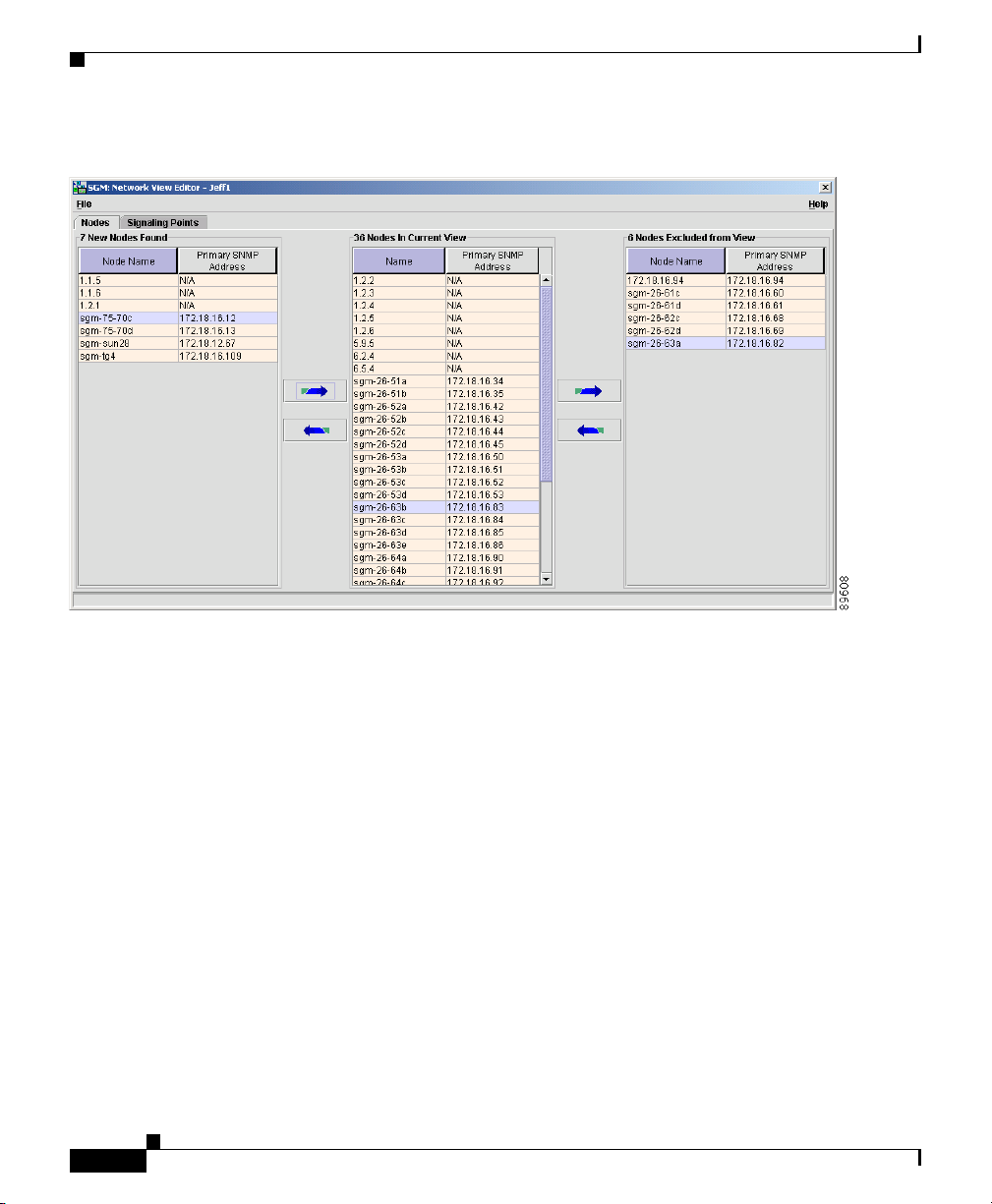
Step 2 Select Edit > Network Views from the SGM Main Menu. SGM displays the
Network View Editor window (Figure 3-7).
78-15589-01
Cisco Signaling Gateway Manager User Guide
3-27
Page 28
Working with Views
Figure 3-7 Network View Editor Window
Chapter 3 Managing ITP Networks Using SGM
3-28
The Nodes panel and Signaling Points panel display:
• New nodes and signaling points that have been found by SGM.
• All nodes and signaling points that are in the current view.
• All nodes and signaling points that have been excluded from the current view.
The Nodes panel and Signaling Points panel also enable you to move nodes and
signaling points into and out of the current view. All changes made in these panels
are reflected in topology tables and maps as soon as you make the changes.
To display the Nodes panel, select the Nodes tab.
To display the Signaling Points panel, select the Signaling Points tab.
Step 3 (Optional) If you have already saved a view and you want to modify it, select the
File > Load menu option. SGM prompts you for the name of the view you want
to load. Enter the name of the view, or accept the default view name, then click
OK to load the view.
Cisco Signaling Gateway Manager User Guide
78-15589-01
Page 29

Chapter 3 Managing ITP Networks Using SGM
Step 4 (Optional) The Nodes In Current View table lists the nodes that are in the current
view. If there are nodes listed in the Nodes In Current View table that you do not
want to manage, you can remove them from the current view. To do so, select one
or more nodes in the Nodes In Current View table, then click the right-arrow
button to move the nodes to the Nodes Excluded from View table.
Note If you are using an SGM client with the DEFAULT view set, SGM
automatically adds all newly discovered nodes to the Nodes In Current
View table as soon as they are discovered.
If you delete a node, SGM removes it from the Nodes In Current View
table. If SGM then discovers the node, SGM places it in the New Nodes
Found table. To see this node again in your current view, you must move
it into the Nodes In Current View table.
At times, you might want to make an existing node a new node. To do so, select
one or more nodes in the Nodes In Current View table, then click the left-arrow
button to move the nodes to the New Nodes Found table.
Step 5 (Optional) The Nodes Excluded from View table lists the nodes that have been
excluded from the current view. To add these nodes to the current view, select
them in the Nodes Excluded from View table and click the left-arrow button to
move the node to the Nodes In Current View table.
At times, you might want to make an excluded node a new node. To do so, select
one or more nodes in the Nodes Excluded From View table, click the left-arrow
button to move the node to the Nodes In Current View table, then click the next
left-arrow button to move the nodes to the New Nodes Found table.
Working with Views
78-15589-01
Step 6 (Optional) The New Nodes Found table displays newly discovered nodes, based
on the following criteria:
• If you are using an SGM client with the DEFAULT view set, this table never
contains any nodes. In the DEFAULT view, SGM adds all newly discovered
nodes to the Nodes In Current View table as soon as they are discovered.
• If you are using an SGM client with a custom view set, this table contains all
nodes discovered since the Network View Editor window was opened in this
session that have not been excluded in the Nodes Excluded from View table,
or that are not in the current view.
Cisco Signaling Gateway Manager User Guide
3-29
Page 30

Working with Views
Step 7 (Optional) The Signaling Points In Current View table lists the signaling points
Chapter 3 Managing ITP Networks Using SGM
When SGM discovers one or more new nodes in the network, SGM also takes the
following actions:
• SGM broadcasts the discovery of the new nodes to all SGM clients.
• SGM displays the text (New Nodes Exist) in the bottom right corner of most
SGM windows.
• SGM adds graphical elements for the newly discovered nodes to the topology
new signaling point panel in the left pane of the Topology window. For more
information, see the “Viewing the Topology of the Network” section on
page 3-259.
To add a newly discovered node to the current view, select one or more nodes and
click the right-arrow button to move them to the Nodes In Current View table.
To exclude a newly discovered node from the current view, select the node, click
the right-arrow button to move the node to the Nodes In Current View table, then
click the next right-arrow button to move the node to the Nodes Excluded From
View table.
that are in the current view. If there are signaling points listed in the Signaling
Points In Current View table that you do not want to manage, you can remove
them from the current view. To do so, select one or more signaling points in the
Signaling Points In Current View table, then click the right-arrow button to move
the signaling points to the Signaling Points Excluded from View table.
3-30
Note If you are using an SGM client with the DEFAULT view set, SGM
automatically adds all newly discovered signaling points to the Signaling
Points In Current View table as soon as they are discovered.
If you delete a signaling point, SGM removes it from the Signaling Points
In Current View table. If SGM then discovers the signaling point, SGM
places it in the New Signaling Points Found table. To see this signaling
point again in your current view, you must move it into the Signaling
Points In Current View table.
At times, you might want to make an existing signaling point a new signaling
point. To do so, select one or more signaling points in the Signaling Points In
Current View table, then click the left-arrow button to move the signaling points
to the New Signaling Points Found table.
Cisco Signaling Gateway Manager User Guide
78-15589-01
Page 31

Chapter 3 Managing ITP Networks Using SGM
Step 8 (Optional) The Signaling Points Excluded from View table lists the signaling
points that have been excluded from the current view. To add these signaling
points to the current view, select them in the Signaling Points Excluded from View
table and click the left-arrow button to move the signaling point to the Signaling
Points In Current View table.
At times, you might want to make an excluded signaling point a new signaling
point. To do so, select one or more signaling points in the Signaling Points
Excluded From View table, click the left-arrow button to move the signaling point
to the Signaling Points In Current View table, then click the next left-arrow button
to move the signaling points to the New Signaling Points Found table.
Step 9 (Optional) The New Signaling Points Found table displays newly discovered
signaling points, based on the following criteria:
• If you are using an SGM client with the DEFAULT view set, this table never
contains any signaling points. In the DEFAULT view, SGM adds all newly
discovered signaling points to the Signaling Points In Current View table as
soon as they are discovered.
• If you are using an SGM client with a custom view set, this table contains all
signaling points discovered since the Network View Editor window was
opened in this session that have not been excluded in the Signaling Points
Excluded from View table, or that are not in the current view.
Working with Views
78-15589-01
When SGM discovers one or more new signaling points in the network, SGM also
takes the following actions:
• SGM broadcasts the discovery of the new signaling points to all SGM clients.
• SGM displays the text (New Signaling Points Exist) in the bottom right
corner of most SGM windows.
• SGM adds graphical elements for the newly discovered signaling points to the
topology new signaling point panel in the left pane of the Topology window.
For more information, see the “Viewing the Topology of the Network” section
on page 3-259.
To add a newly discovered signaling point to the current view, select one or more
signaling points and click the right-arrow button to move them to the Signaling
Points In Current View table.
To exclude a newly discovered signaling point from the current view, select the
signaling point, click the right-arrow button to move the signaling point to the
Signaling Points In Current View table, then click the next right-arrow button to
move the signaling point to the Signaling Points Excluded From View table.
Cisco Signaling Gateway Manager User Guide
3-31
Page 32

Working with Views
Step 10 When you are satisfied with the changes you have made to the view, use one of
Chapter 3 Managing ITP Networks Using SGM
the following procedures to save the view:
• To save the changes you have made to the view without changing the name of
the file, select File > Save from the Network View Editor menu.
Note You cannot save changes to the DEFAULT view. If you are currently
using the DEFAULT view and you select File > Save, SGM displays
the Save File Dialog: View List dialog (Figure 3-8).
• To save the changes you have made to the view with a new name, select File
> Save As from the Discovery Dialog menu. SGM displays the Save File
Dialog: View List dialog (Figure 3-8).
Figure 3-8 Save File Dialog: View List Dialog
3-32
Cisco Signaling Gateway Manager User Guide
78-15589-01
Page 33

Chapter 3 Managing ITP Networks Using SGM
The Save File Dialog: View List dialog contains the following fields:
–
Type—Icon indicating whether the item in the table is a file or a folder.
–
Name—Name of the view file or folder.
–
Last Modified—Date and time the view file or folder was last modified.
–
Size (bytes)—Size of the view file or folder, in bytes.
–
Filename—Name by which you want to save the view. You must specify
a name other than DEFAULT. You cannot save changes to the DEFAULT
view.
If you create a new view name, you can use any letters, numbers, or
characters in the name that are allowed by your operating system.
However, if you include any spaces in the new name, SGM converts those
spaces to dashes. For example, SGM saves file “a b c” as “a-b-c”.
–
Make this my preferred start option—Specifies whether the selected
view is to be loaded automatically whenever the associated preferences
file is loaded:
- To load the selected view, select the view, then select this checkbox.
- To load the last-used view, clear the checkbox. This is the default
setting.
–
Number of Files—Total number of view files and folders (displayed in
bottom left corner).
Working with Views
78-15589-01
To save the view with a new name, use one of the following procedures:
–
To save the file with a completely new name, enter the new name and
click OK.
–
To save the file with an existing name, overwriting an old view, select the
name in the list and click OK.
SGM saves the view with the new name, closes the Save File Dialog: View
List dialog, and returns to the Discovery Dialog.
Note If another user modifies and saves the view before you save your
changes, SGM asks if you want to overwrite that user’s changes. If
you choose to do so, the other user’s changes are overwritten and lost.
If you choose not to do so, your changes are lost, unless you save the
view to a different filename.
Cisco Signaling Gateway Manager User Guide
3-33
Page 34

Working with Views
Step 11 (Optional) To close the Network View Editor window at any time, click File >
Chapter 3 Managing ITP Networks Using SGM
SGM stores the view in the view file directory on the SGM server:
–
If you installed SGM in the default directory, /opt, then the SGM view
file directory is /opt/CSCOsgm/views.
–
If you installed SGM in a different directory, then the SGM view file
directory is located in that directory.
To delete a view from the view list, select a file and click Delete. SGM issues
an informational message containing the name and location of the deleted
file.
To save any changes you made to the list of files, click OK. SGM saves the
changes and closes the Load File Dialog: View List dialog.
To close the Save File Dialog: View List dialog without saving the view or
saving any changes to the view list, click Cancel.
Close. If you have modified the view, SGM asks if you want to apply the changes
before leaving the window:
• Click Yes to apply the changes to the current view. SGM applies the changes
to all SGM windows immediately. SGM then asks if you want to make this
the default view:
3-34
–
Click Ye s to make this view the new default view. In the future, when this
client is started, this will be the default view.
–
Click No to retain your old default view.
SGM closes the Network View Editor window.
• Click No to keep the current view as-is, without applying any changes. SGM
closes the Network View Editor window.
• Click Cancel to close the prompt window and return to the Network View
Editor window without applying any changes to the current view.
If you are working in a custom view (that is, not in the DEFAULT view) and you
exit the SGM client, SGM automatically saves any changes you made to the view.
Cisco Signaling Gateway Manager User Guide
78-15589-01
Page 35

Chapter 3 Managing ITP Networks Using SGM
Loading the DEFAULT View
To load the DEFAULT network view:
Step 1 Select Edit > Network Views from the SGM Main Menu. SGM displays the
Network View Editor window (Figure 3-7).
Step 2 Select File > Load DEFAULT View from the Discovery Dialog menu. SGM
loads the DEFAULY view.
Loading a Client-Specific View
To load a client-specific network view:
Step 1 Select Edit > Network Views from the SGM Main Menu. SGM displays the
Network View Editor window (Figure 3-7).
Step 2 Select File > Load from the Discovery Dialog menu. SGM displays the Load File
Dialog: View List dialog (Figure 3-9).
Working with Views
78-15589-01
Cisco Signaling Gateway Manager User Guide
3-35
Page 36

Working with Views
Chapter 3 Managing ITP Networks Using SGM
Figure 3-9 Load File Dialog: View List Dialog
3-36
The Load File Dialog: View List dialog contains the following fields:
• Type—Icon indicating whether the item in the table is a file or a folder.
• Name—Name of the view file or folder.
• Last Modified—Date and time the view file or folder was last modified.
• Size (bytes)—Size of the view file or folder, in bytes.
• Make this my preferred start option—Specifies whether the selected view
is to be loaded automatically whenever the associated preferences file is
loaded:
–
To load the selected view, select the view, then select this checkbox.
–
To load the last-used view, clear the checkbox. This is the default setting.
• Number of Files—Total number of view files and folders (displayed in
bottom left corner).
To load a view, select the view in the list and click OK.
Cisco Signaling Gateway Manager User Guide
78-15589-01
Page 37

Chapter 3 Managing ITP Networks Using SGM
SGM closes the Load File Dialog: View List dialog, loads the view, and returns to
the Network View Editor window.
To close the Load File Dialog: View List dialog without loading a view, click
Cancel.
Working with Linksets
SGM enables you to view information about all discovered linksets, including
their associated nodes, status, and other important information.
This section includes the following information:
• Viewing Basic Information for Linksets, page 3-38
• Viewing Detailed Information for a Linkset, page 3-42
• Viewing Real-Time Data for a Linkset, page 3-54
• Editing a Linkset, page 3-84
• Viewing Notes for a Linkset, page 3-87
• Deleting a Linkset, page 3-88
Working with Linksets
78-15589-01
• Ignoring a Linkset, page 3-90
• Viewing Ignored Linksets, page 3-90
Related Topics:
• Modifying Preference Settings, page 5-3
• Resizing, Sorting, and Hiding Table Columns, page 3-279
• Viewing the Topology of the Network, page 3-259
• Working with Links, page 3-170
• Working with Nodes, page 3-91
• Working with Signaling Points, page 3-136
Cisco Signaling Gateway Manager User Guide
3-37
Page 38

Working with Linksets
Viewing Basic Information for Linksets
To view basic information for linksets, select Linksets in the left pane of the SGM
Main Window. SGM displays the Linkset Window (Figure 3-10).
Figure 3-10 Linkset Window
Chapter 3 Managing ITP Networks Using SGM
3-38
The Linkset Window displays information about the linksets that have been
discovered by SGM.
Linksets that are associated with nodes that are excluded from the current view
are not displayed in the Linkset Window. See the “Creating a View” section on
page 3-27 for more information about excluding nodes.
By default, SGM displays all of the columns in the Linkset Window except
Internal ID, Name, Local Point Code, Adj Point Code, and Notes. To display
these columns, or to hide other columns, see the procedures in the “Modifying
Linkset Table Column Settings” section on page 5-18.
To see mouse over help popup for each column in the table, place the cursor over
a column header.
If a cell is too small to show all of its data, place the cursor over the cell to see the
full data in a mouse over help popup.
Cisco Signaling Gateway Manager User Guide
78-15589-01
Page 39

Chapter 3 Managing ITP Networks Using SGM
You can resize each column, or sort the table based on the information in one of
the columns. See the “Resizing, Sorting, and Hiding Table Columns” section on
page 3-279 for more details.
The Linkset Window displays the following information for each discovered
linkset:
• Internal ID—The internal ID of the linkset. The internal ID is a unique ID
for every event, link, linkset, signaling point, and node, assigned by SGM for
its own internal use. It can also be useful when the TAC is debugging
problems.
• Name—Name of the linkset.
• Local Point Code—Point code of the primary node for the linkset.
• Adj Point Code—Point code of the adjacent node for the linkset.
• Linkset Type—Type of linkset, which SGM determines by examining the
links defined in the linkset. Possible linkset types are:
–
HSL—The links in this linkset use the SS7-over-ATM (Asynchronous
Transfer Mode) high-speed protocol.
–
SCTPIP—The links in this linkset use the Stream Control Transmission
Protocol (SCTP) IP transport protocol.
–
Serial—The links in this linkset use the serial SS7 signaling protocol.
–
Mixed—The links in this linkset are of two or more types. (This
arrangement is not recommended.)
Working with Linksets
78-15589-01
–
Virtual—The links in this linkset are virtual links, which connect
signaling point instances running on the same device. SGM does not poll
virtual linksets, nor does it display real-time data or accounting statistics
for virtual linksets.
–
Other—No links have been defined for this linkset.
• Links—Total number of links in the linkset.
• Active Links—Number of links in the linkset that are Active.
• Congested Links—Number of links in the linkset that are Congested.
• Ignored—Indicates whether the linkset is to be included when aggregating
and displaying SGM status information.
• Notes— Indicates whether there is a note associated with the linkset.
Cisco Signaling Gateway Manager User Guide
3-39
Page 40

Working with Linksets
Chapter 3 Managing ITP Networks Using SGM
• Events—Indicates whether there is a recent event associated with the linkset.
–
To delete the event icon from SGM displays for a specific linkset, for this
SGM client only, select the linkset and click the icon.
–
To delete the event icon from SGM displays for all linksets, for this SGM
client only, select Edit > Clear All Events from the SGM Main Menu.
Note During Discovery, SGM might flag most linksets with an event
icon. If the event icons are too distracting, use the Edit > Clear
All Events menu option to remove them.
• Last Status Change—Date and time that the status of the linkset last
changed.
• Status—Current status of the linkset. Possible values are:
–
Active (green ball)—The linkset is currently fully functional.
–
Unavailable (red ball)—An error is preventing traffic from flowing on
this linkset.
–
Shutdown (blue ball)—An ITP administrator has set the linkset to
prevent traffic from flowing. When a linkset is set to Shutdown, all its
associated links are set to Failed by Cisco IOS.
–
Unknown (red ball)—Either the node associated with this linkset has
failed to respond to an SNMP request, or SGM found that the linkset no
longer exists.
–
Warning (yellow ball)—The linkset is active, but one or more links in
the linkset is congested or is in Failed, Unknown, or Warning status,
and is not Ignored. At least one link is available and can carry traffic.
3-40
• Status Reason—Reason for the current status of the linkset. Possible values
are:
–
None
–
SGM Restart
–
Unsupported Configuration
–
Unconfigured
–
SNMP Timeout
–
Device is unreachable, possibly wrong community string
Cisco Signaling Gateway Manager User Guide
78-15589-01
Page 41

Chapter 3 Managing ITP Networks Using SGM
–
Not ITP Device
–
Not Configured for ITP
–
MIB Data Error
–
SNMP Exception
–
SignalingPoint Inactive
–
Linkset Inactive
–
Link Congested
–
Link Send Utilization Threshold Exceeded
–
Link Receive Utilization Threshold Exceeded
–
Link Local Interface Inactive
–
Link Remote Interface Inactive
–
Link Inactive
If the cell is too small to show all of the status reason, place the cursor over
the cell to see the full status reason in a mouse over help popup.
The status reasons are listed in order of decreasing magnitude. If two or more
reasons apply, the reason of greatest magnitude is displayed.
Working with Linksets
78-15589-01
If the status reason is Unsupported Configuration, correct the configuration
and enter the sgm cleandiscover command to delete all current network data
and begin a clean discovery of the ITP network. If the status reason is still
Unsupported Configuration, enter the sgm clean command to restore the
SGM server to a “clean” state, such as would exist after a new installation of
SGM. For more information on the use of these commands, see the “SGM
Commands and Descriptions” section on page B-2.
The “Viewing Detailed Information for a Link” section on page 3-175
displays additional information about the causes of link failures.
The “Viewing Detailed Information for a Linkset” section on page 3-42
displays additional information about the causes of linkset failures.
Cisco Signaling Gateway Manager User Guide
3-41
Page 42

Chapter 3 Managing ITP Networks Using SGM
Working with Linksets
Viewing Detailed Information for a Linkset
SGM can display detailed information about a selected linkset, including its
associated links, status, and other information.
To display detailed information for a linkset, use one of the following procedures:
• Select Linksets in the left pane of the SGM Main Window, right-click a
linkset in the right pane, then select View> Configuration Details in the
right-click menu.
• Select the turner beside Linksets in the left pane of the SGM Main Window,
then select a linkset.
SGM displays the Linkset Details Window (Figure 3-11).
Figure 3-11 Linkset Details Window
3-42
Detailed information for the selected linkset is displayed in the left column, and
for the adjacent linkset in the right column.
Updates for the linkset that are received from the SGM server are reflected
automatically in this window.
Cisco Signaling Gateway Manager User Guide
78-15589-01
Page 43

Chapter 3 Managing ITP Networks Using SGM
Changes you make in this pane might not be reflected throughout SGM until the
next poll (by default, every 15 seconds). For information about changing the
polling interval, see the “Viewing Detailed Information for a Link” section on
page 3-175.
Note This window polls your network periodically. To prevent unnecessary traffic on
your network, close this window when you no longer need to refer to it.
Links Tab
To view information about the links that are associated with the selected linkset,
select the Links tab. SGM displays the linksets in the top table, and the links in
the bottom table.
To see mouse over help popup for each column in the table, place the cursor over
a column header.
If a cell is too small to show all of its data, place the cursor over the cell to see the
full data in a mouse over help popup.
You can resize each column, or sort the table based on the information in one of
the columns. See the “Resizing, Sorting, and Hiding Table Columns” section on
page 3-279 for more details.
Working with Linksets
78-15589-01
By default, SGM displays all of the columns in the Link Table except Internal
ID, Congestion Level, and Last Status Change. To display these columns, or to
hide other columns, see the procedures in the “Modifying Linkset Table Column
Settings” section on page 5-18.
The Link Table displays the following information about links that are associated
with the selected linkset:
• Internal ID—Internal ID of the link. The internal ID is a unique ID for every
event, linkset, link, signaling point, and node, assigned by SGM for its own
internal use. It can also be useful when the TAC is debugging problems.
• Node—Name of the node associated with the link.
• Signaling Point—Name of the signaling point associated with the link.
• Linkset—Name of the linkset associated with the link.
• SLC—Signaling link code (SLC) ID for the link.
Cisco Signaling Gateway Manager User Guide
3-43
Page 44

Working with Linksets
Chapter 3 Managing ITP Networks Using SGM
• Type—Type of link. Possible link types are:
–
HSL—The link uses the SS7-over-ATM (Asynchronous Transfer Mode)
high-speed protocol.
–
SCTPIP—The link uses the Stream Control Transmission Protocol
(SCTP) IP transport protocol.
–
Serial—The link uses the serial SS7 signaling protocol.
–
Virtual—The link is a virtual link, which connects signaling point
instances running on the same device. SGM does not poll virtual links,
nor does it display real-time data or accounting statistics for virtual links.
• Congestion Level—Indicates whether there is congestion on the link. A link
is congested if it has too many packets waiting to be sent. This condition
could be caused by the failure of an element in your network.
Possible values for the Congestion Level field are:
–
None—The link is not congested.
–
Low—The link is slightly congested.
–
High—The link is congested.
–
Very High—The link is very congested.
3-44
Low, High, and Very High correspond roughly to equivalent ANSI,
China standard, and ITU congestion levels.
• Ignored—Indicates whether the link is to be included when aggregating and
displaying SGM status information:
–
Clear the checkbox to include the link. This is the default setting.
–
Select the checkbox to exclude the link.
This field can be edited by users with authentication level Power User (Level
2) and higher.
• Notes—Indicates whether there is a note associated with the link.
Cisco Signaling Gateway Manager User Guide
78-15589-01
Page 45

Chapter 3 Managing ITP Networks Using SGM
• Events—Indicates whether there is a recent event associated with the link.
–
To delete the event icon from SGM displays for a specific link, select the
link and click the icon.
–
To delete the event icon from SGM displays for all links, select
Edit>Clear All Events from the SGM Main Menu.
Note During Discovery, SGM might flag most links with an event icon. If the
event icons are too distracting, use the Edit>Clear All Events menu
option to remove them.
• Last Status Change—Date and time that the status of the link last changed.
• Status—Current status of the link. Possible values are:
–
Active (green ball)—The link is currently fully functional.
–
Blocked (red ball)—Traffic on this link is disabled by protocol.
–
Failed (red ball)—An error is preventing traffic from flowing on this
link, or the associated linkset has been set to Shutdown status.
A link can be Failed from an MTP3 perspective, but control messages
might still be sent or received on the link, resulting in changing
packet/second and bit/second rates. The rates might also be different at
each end of the link, depending on the reason for the failure and the
timing related to each endpoint.
–
InhibitLoc (blue ball)—A local ITP administrator has set the link to
prevent traffic from flowing.
Working with Linksets
78-15589-01
–
InhibitRem (blue ball)—A remote ITP administrator has set the link to
prevent traffic from flowing.
–
Shutdown (blue ball)—An ITP administrator has set the link to prevent
traffic from flowing.
Cisco Signaling Gateway Manager User Guide
3-45
Page 46

Working with Linksets
Chapter 3 Managing ITP Networks Using SGM
–
Unknown (red ball)—Either the node associated with this link has failed
to respond to an SNMP request, or SGM found that the link no longer
exists.
When you physically delete a link, the Status field displays Unknown
until you delete the link from the SGM database.
–
Warning (yellow ball)—The link is active and traffic is flowing, but one
or more of the following situations has occurred:
– The link is congested.
– The link has exceeded the defined Receive Utilization % or Send
Utilization %.
– One or more of the local or remote IP addresses defined for SCTP is
not active.
• Status Reason—Reason for the current status of the link. Possible values are:
–
None
–
SGM Restart
–
Unsupported Configuration
–
Unconfigured
3-46
–
SNMP Timeout
–
Device is unreachable, possibly wrong community string
–
Not ITP Device
–
Not Configured for ITP
–
MIB Data Error
–
SNMP Exception
–
SignalingPoint Inactive
–
Linkset Inactive
–
Link Congested
–
Link Send Utilization Threshold Exceeded
–
Link Receive Utilization Threshold Exceeded
–
Link Local Interface Inactive
Cisco Signaling Gateway Manager User Guide
78-15589-01
Page 47

Chapter 3 Managing ITP Networks Using SGM
–
Link Remote Interface Inactive
–
Link Inactive
If the cell is too small to show all of the status reason, place the cursor over
the cell to see the full status reason in a mouse over help popup.
The status reasons are listed in order of decreasing magnitude. If two or more
reasons apply, the reason of greatest magnitude is displayed.
If the status reason is Unsupported Configuration, correct the configuration
and enter the sgm cleandiscover command to delete all current network data
and begin a clean discovery of the ITP network. If the status reason is still
Unsupported Configuration, enter the sgm clean command to restore the
SGM server to a “clean” state, such as would exist after a new installation of
SGM. For more information on the use of these commands, see the “SGM
Commands and Descriptions” section on page B-2.
Configuration Data Tab: Naming Information
To view naming information for the selected linkset, select the Configuration
Data tab.
The Naming Information sub-section displays the following information for the
selected linkset:
• Name—Name of the linkset.
Working with Linksets
78-15589-01
• Local Point Code—Point code of the primary node for the linkset.
• Adj Point Code—Point code of the adjacent node for the linkset.
• Last Status Change—Date and time that the status of the linkset last
changed.
• Status—Current status of the linkset. Possible values are:
–
Active (green ball)—The linkset is currently fully functional.
–
Unavailable (red ball)—An error is preventing traffic from flowing on
this linkset.
–
Shutdown (blue ball)—An ITP administrator has set the linkset to
prevent traffic from flowing. When a linkset is set to Shutdown, all its
associated links are set to Failed by Cisco IOS.
Cisco Signaling Gateway Manager User Guide
3-47
Page 48

Working with Linksets
Chapter 3 Managing ITP Networks Using SGM
–
Unknown (red ball)—Either the node associated with this linkset has
failed to respond to an SNMP request, or SGM found that the linkset no
longer exists.
–
Warning (yellow ball)—The linkset is active, but one or more links in
the linkset is congested or is in Failed, Unknown, or Warning status,
and is not Ignored. At least one link is available and can carry traffic.
• Status Reason—Reason for the current status of the linkset. Possible values
are:
–
None
–
SGM Restart
–
Unsupported Configuration
–
Unconfigured
–
SNMP Timeout
–
Device is unreachable, possibly wrong community string
–
Not ITP Device
–
Not Configured for ITP
3-48
–
MIB Data Error
–
SNMP Exception
–
SignalingPoint Inactive
–
Linkset Inactive
–
Link Congested
–
Link Send Utilization Threshold Exceeded
–
Link Receive Utilization Threshold Exceeded
–
Link Local Interface Inactive
–
Link Remote Interface Inactive
–
Link Inactive
If the cell is too small to show all of the status reason, place the cursor over
the cell to see the full status reason in a mouse over help popup.
The status reasons are listed in order of decreasing magnitude. If two or more
reasons apply, the reason of greatest magnitude is displayed.
Cisco Signaling Gateway Manager User Guide
78-15589-01
Page 49

Chapter 3 Managing ITP Networks Using SGM
If the status reason is Unsupported Configuration, correct the configuration
and enter the sgm cleandiscover command to delete all current network data
and begin a clean discovery of the ITP network. If the status reason is still
Unsupported Configuration, enter the sgm clean command to restore the
SGM server to a “clean” state, such as would exist after a new installation of
SGM. For more information on the use of these commands, see the “SGM
Commands and Descriptions” section on page B-2.
Configuration Data Tab: Description
To view descriptive information for the selected linkset, select the Configuration
Data tab.
The Description sub-section contains a description of the linkset. If the linkset has
no description, this sub-section is blank.
Configuration Data Tab: General Information
To view general information for the selected linkset, select the Configuration
Data tab.
The General Information sub-section displays the following information for the
selected linkset:
Working with Linksets
78-15589-01
• Linkset Type—Type of linkset, which SGM determines by examining the
links defined in the linkset. Possible linkset types are:
–
HSL—The links in this linkset use the SS7-over-ATM (Asynchronous
Transfer Mode) high-speed protocol.
–
SCTPIP—The links in this linkset use the Stream Control Transmission
Protocol (SCTP) IP transport protocol.
–
Serial—The links in this linkset use the serial SS7 signaling protocol.
–
Mixed—The links in this linkset are of two or more types. (This
configuration is not recommended.)
–
Virtual—The links in this linkset are virtual links, which connect
signaling point instances running on the same device. SGM does not poll
virtual linksets, nor does it display real-time data or accounting statistics
for virtual linksets.
–
Other—No links have been defined for this linkset.
Cisco Signaling Gateway Manager User Guide
3-49
Page 50

Working with Linksets
Chapter 3 Managing ITP Networks Using SGM
• Is Ignored—Indicates whether the linkset is Ignored (that is, whether the
linkset is to be included when aggregating and displaying SGM status
information).
• Inbound ACL—Inbound IP access control list (ACL) number for the linkset.
If there is no inbound ACL for the linkset, this field displays 0.
• Outbound ACL—Outbound ACL number for the linkset. If there is no
outbound ACL for the linkset, this field displays 0.
Configuration Data Tab: Links Information
To view links information for the selected linkset, select the Configuration Data
tab.
The Links Information sub-section displays the following information for the
selected linkset:
• Links—Total number of links in the linkset.
• Active Links—Number of links in the linkset that are Active.
• Congested Links—Number of links in the linkset that are Congested.
3-50
Notes Tab
To view notes for the selected linkset, select the Notes tab.
The Notes section displays:
• Notes associated with the selected linkset in the left column.
• Notes associated with the adjacent linkset in the right column.
• The date and time the notes associated with each linkset were last updated, or
the phrase Not Set if there are no notes associated with the linkset.
• The phrase No Notes if there are no notes associated with the linkset.
Recent Events Tab
To view information about all recent events associated with the linkset, select the
Recent Events tab. SGM displays the Recent Events table for the linkset
(Figure 3-12).
Cisco Signaling Gateway Manager User Guide
78-15589-01
Page 51

Chapter 3 Managing ITP Networks Using SGM
Figure 3-12 Recent Events Table for a Linkset
Working with Linksets
78-15589-01
By default, SGM displays all of the columns in the table except Internal ID,
Note, Ack By, Ack Time, Node, SP, Linkset, and Link. To display these
columns, or to hide other columns, see the procedures in the “Modifying Event
Table Column Settings” section on page 5-19.
To see mouse over help popup for each column in the table, place the cursor over
a column header.
If a cell is too small to show all of its data, place the cursor over the cell to see the
full data in a mouse over help popup.
You can resize each column, or sort the table based on the information in one of
the columns. See the “Resizing, Sorting, and Hiding Table Columns” section on
page 3-279 for more details.
The Recent Events table enables you to perform event-related tasks, such as
setting filters and acknowledging events. For more information about these tasks,
see the “Working with Events” section on page 3-235.
Cisco Signaling Gateway Manager User Guide
3-51
Page 52

Working with Linksets
Chapter 3 Managing ITP Networks Using SGM
The Recent Events table displays the following information for the selected
linkset:
• Internal ID—Internal ID of the event. The internal ID is a unique ID for
every event, link, linkset, signaling point, and node, assigned by SGM for its
own internal use. It can also be useful when the TAC is debugging problems.
• Ack—Indicates whether the event has been acknowledged:
–
To acknowledge an unacknowledged event, use the Acknowledge toolbar
button.
–
To make a previously acknowledged event unacknowledged, use the
Unacknowledge toolbar button.
• Category—Type of the event. Default values are:
–
Create—Creation event, such as the creation of a seed file.
–
Delete—Deletion event, such as the deletion of a node, signaling point,
linkset, or file.
–
Discover—Discovery event, such as Discovery beginning.
–
Edit—Edit event. A user has edited a node, signaling point, linkset, or
link.
–
Ignore—Ignore event. A user has Ignored a link or linkset.
3-52
–
Login—Login event. A user has logged in to SGM.
–
LoginDisable—LoginDisable event. SGM has disabled a user’s
User-Based Access authentication as a result of too many failed attempts
to log in to SGM.
–
LoginFail—LoginFail event. An attempt by a user to log in to SGM has
failed.
–
OverWrite—OverWrite event. An existing file, such as a seed file or
route file, has been overwritten.
–
Poll—Poll event, such as an SNMP poll.
–
Purge—Purge event. A user has requested Discovery with Delete
Existing Data selected, and SGM has deleted the existing SGM
database.
Cisco Signaling Gateway Manager User Guide
78-15589-01
Page 53

Chapter 3 Managing ITP Networks Using SGM
–
Status—Status change message generated.
–
Trap—SNMP trap message generated.
You can customize this field. See the “Modifying the SGM Event
Configuration File (Solaris Only)” section on page 5-26 for more
information.
• Severity—Severity of the event. Default values are:
–
Admin—The default color is cyan.
–
Error—The default color is coral.
–
None—The default color is white.
–
Normal—The default color is light green.
–
Warning—The default color is yellow.
You can customize this field. See the “Modifying the SGM Event
Configuration File (Solaris Only)” section on page 5-26 for more
information.
• Note—Indicates whether there is a note associated with the event.
• Time—Date and time the event was logged.
• Ack By—If you have not implemented SGM User-Based Access, name of the
device that last acknowledged the event.
If you have implemented SGM User-Based Access, name of the user who last
acknowledged the event.
Working with Linksets
78-15589-01
If no one has acknowledged the event, this field is blank.
• Ack Time—Date and time the event was last acknowledged or
unacknowledged.
• Node—Name of the node associated with the event. If there is no node
associated with the event, None is displayed.
• SP—Name of the signaling point associated with the event. If there is no
signaling point associated with the event, None is displayed.
• Linkset—Name of the linkset associated with the event. If there is no linkset
associated with the event, None is displayed.
Cisco Signaling Gateway Manager User Guide
3-53
Page 54

Working with Linksets
Chapter 3 Managing ITP Networks Using SGM
• Link—Name of the link associated with the event. If there is no link
associated with the event, None is displayed.
• Message—Text of the message.
You can customize this field. See the “Modifying the SGM Event
Configuration File (Solaris Only)” section on page 5-26 for more
information.
ITP Access Lists Tab
To view information about all access lists associated with the selected linkset and
its adjacent linkset, select the ITP Access Lists tab.
For each linkset, the ITP Access Lists section displays the following information:
• Current Poll Interval—Poll interval used to collect data for the table.
• Last Poll—Time the last poll was run. This field initially displays the phrase
Polling device. After the first polling cycle, SGM populates this field with the
actual time of the last poll.
• Linkset—Name of the linkset for which access lists are being displayed.
• In—Inbound access lists for the linkset. If the linkset has no inbound access
lists, this field displays None.
• Out—Outbound access lists for the linkset. If the linkset has no outbound
access lists, this field displays None.
• List #—Access list number configured on the node and applied to the linkset.
ITP uses access list numbers 2700 through 2799.
• Access List—List of commands in the access list.
Viewing Real-Time Data for a Linkset
SGM enables you to display detailed statistics for a selected linkset, including its
associated links, status, and other information. Detailed information for the
selected linkset is displayed in the left column, and for the adjacent linkset in the
right column.
To display detailed statistics for a linkset, select Linksets in the left pane of the
SGM Main Window, right-click a linkset in the right pane, then select
View>Real-Time Data and Charts in the right-click menu. SGM displays the
Statistics Details Window for a Linkset (Figure 3-13).
Cisco Signaling Gateway Manager User Guide
3-54
78-15589-01
Page 55

Chapter 3 Managing ITP Networks Using SGM
Figure 3-13 Statistics Details Window for a Linkset
Working with Linksets
78-15589-01
Updates for the linksets that are received from the SGM server are reflected
automatically in this window.
Changes you make in this window might not be reflected throughout SGM until
the next poll (by default, every 15 seconds). For information about changing the
polling interval, see the “Viewing Detailed Information for a Link” section on
page 3-175.
Note This window polls your network periodically. To prevent unnecessary traffic on
your network, close this window when you no longer need to refer to it.
Cisco Signaling Gateway Manager User Guide
3-55
Page 56

Working with Linksets
Chapter 3 Managing ITP Networks Using SGM
Configuration Data Tab: Naming Information
To view naming information for the selected linkset, select the Configuration
Data tab.
The Naming Information sub-section displays the following information for the
selected linkset:
• Name—Name of the linkset.
• Local Point Code—Point code of the primary node for the linkset.
• Adj Point Code—Point code of the adjacent node for the linkset.
• Last Status Change—Date and time that the status of the linkset last
changed.
• Status—Current status of the linkset. Possible values are:
–
Active (green ball)—The linkset is currently fully functional.
–
Unavailable (red ball)—An error is preventing traffic from flowing on
this linkset.
–
Shutdown (blue ball)—An ITP administrator has set the linkset to
prevent traffic from flowing. When a linkset is set to Shutdown, all its
associated links are set to Failed by Cisco IOS.
–
Unknown (red ball)—Either the node associated with this linkset has
failed to respond to an SNMP request, or SGM found that the linkset no
longer exists.
–
Warning (yellow ball)—The linkset is active, but one or more links in
the linkset is congested or is in Failed, Unknown, or Warning status,
and is not Ignored. At least one link is available and can carry traffic.
• Status Reason—Reason for the current status of the linkset. Possible values
are:
–
None
3-56
–
SGM Restart
–
Unsupported Configuration
–
Unconfigured
–
SNMP Timeout
–
Device is unreachable, possibly wrong community string
–
Not ITP Device
Cisco Signaling Gateway Manager User Guide
78-15589-01
Page 57

Chapter 3 Managing ITP Networks Using SGM
–
Not Configured for ITP
–
MIB Data Error
–
SNMP Exception
–
SignalingPoint Inactive
–
Linkset Inactive
–
Link Congested
–
Link Send Utilization Threshold Exceeded
–
Link Receive Utilization Threshold Exceeded
–
Link Local Interface Inactive
–
Link Remote Interface Inactive
–
Link Inactive
If the cell is too small to show all of the status reason, place the cursor over
the cell to see the full status reason in a mouse over help popup.
The status reasons are listed in order of decreasing magnitude. If two or more
reasons apply, the reason of greatest magnitude is displayed.
If the status reason is Unsupported Configuration, correct the configuration
and enter the sgm cleandiscover command to delete all current network data
and begin a clean discovery of the ITP network. If the status reason is still
Unsupported Configuration, enter the sgm clean command to restore the
SGM server to a “clean” state, such as would exist after a new installation of
SGM. For more information on the use of these commands, see the “SGM
Commands and Descriptions” section on page B-2.
Working with Linksets
78-15589-01
Configuration Data Tab: Description
To view descriptive information for the selected linkset, select the Configuration
Data tab.
The Description sub-section contains a description of the linkset. If the linkset has
no description, this sub-section is blank.
Cisco Signaling Gateway Manager User Guide
3-57
Page 58

Working with Linksets
Chapter 3 Managing ITP Networks Using SGM
Configuration Data Tab: General Information
To view general information for the selected linkset, select the Configuration
Data tab.
The General Information sub-section displays the following information for the
selected linkset:
• Linkset Type—Type of linkset, which SGM determines by examining the
links defined in the linkset. Possible linkset types are:
–
HSL—The links in this linkset use the SS7-over-ATM (Asynchronous
Transfer Mode) high-speed protocol.
–
SCTPIP—The links in this linkset use the Stream Control Transmission
Protocol (SCTP) IP transport protocol.
–
Serial—The links in this linkset use the serial SS7 signaling protocol.
–
Mixed—The links in this linkset are of two or more types. (This
configuration is not recommended.)
–
Virtual—The links in this linkset are virtual links, which connect
signaling point instances running on the same device. SGM does not poll
virtual linksets, nor does it display real-time data or accounting statistics
for virtual linksets.
–
Other—No links have been defined for this linkset.
3-58
• Is Ignored—Indicates whether the linkset is Ignored (that is, whether the
linkset is to be included when aggregating and displaying SGM status
information).
• Inbound ACL—Inbound IP access control list (ACL) number for the linkset.
If there is no inbound ACL for the linkset, this field displays 0.
• Outbound ACL—Outbound ACL number for the linkset. If there is no
outbound ACL for the linkset, this field displays 0.
Cisco Signaling Gateway Manager User Guide
78-15589-01
Page 59

Chapter 3 Managing ITP Networks Using SGM
Configuration Data Tab: Links Information
To view links information for the selected linkset, select the Configuration Data
tab.
The Links Information sub-section displays the following information for the
selected linkset:
• Links—Total number of links in the linkset.
• Active Links—Number of links in the linkset that are Active.
• Congested Links—Number of links in the linkset that are Congested.
Notes Tab
To view notes for the selected linkset, select the Notes tab.
The Notes section displays:
• Notes associated with the selected linkset in the left column.
• Notes associated with the adjacent linkset in the right column.
• The date and time the notes associated with each linkset were last updated, or
the phrase Not Set if there are no notes associated with the linkset.
• The phrase No Notes if there are no notes associated with the linkset.
Working with Linksets
78-15589-01
Recent Events Tab
To view information about all recent events associated with the linkset, select the
Recent Events tab. SGM displays the Recent Events table for the linkset
(Figure 3-12).
By default, SGM displays all of the columns in the table except Internal ID,
Note, Ack By, Ack Time, Node, SP, Linkset, and Link. To display these
columns, or to hide other columns, see the procedures in the “Modifying Event
Table Column Settings” section on page 5-19.
To see mouse over help popup for each column in the table, place the cursor over
a column header.
If a cell is too small to show all of its data, place the cursor over the cell to see the
full data in a mouse over help popup.
You can resize each column, or sort the table based on the information in one of
the columns. See the “Resizing, Sorting, and Hiding Table Columns” section on
page 3-279 for more details.
Cisco Signaling Gateway Manager User Guide
3-59
Page 60

Working with Linksets
Chapter 3 Managing ITP Networks Using SGM
The Recent Events section enables you to perform event-related tasks, such as
setting filters and acknowledging events. For more information about these tasks,
see the “Working with Events” section on page 3-235.
The Recent Events table displays the following information for the selected
linkset:
• Internal ID—Internal ID of the event. The internal ID is a unique ID for
every event, link, linkset, signaling point, and node, assigned by SGM for its
own internal use. It can also be useful when the TAC is debugging problems.
• Ack—Indicates whether the event has been acknowledged:
–
To acknowledge an unacknowledged event, use the Acknowledge toolbar
button.
–
To make a previously acknowledged event unacknowledged, use the
Unacknowledge toolbar button.
• Category—Type of the event. Default values are:
–
Create—Creation event, such as the creation of a seed file.
–
Delete—Deletion event, such as the deletion of a node, signaling point,
linkset, or file.
–
Discover—Discovery event, such as Discovery beginning.
–
Edit—Edit event. A user has edited a node, signaling point, linkset, or
link.
3-60
–
Ignore—Ignore event. A user has Ignored a link or linkset.
–
Login—Login event. A user has logged in to SGM.
–
LoginDisable—LoginDisable event. SGM has disabled a user’s
User-Based Access authentication as a result of too many failed attempts
to log in to SGM.
–
LoginFail—LoginFail event. An attempt by a user to log in to SGM has
failed.
–
OverWrite—OverWrite event. An existing file, such as a seed file or
route file, has been overwritten.
–
Poll—Poll event, such as an SNMP poll.
–
Purge—Purge event. A user has requested Discovery with Delete
Existing Data selected, and SGM has deleted the existing SGM
database.
Cisco Signaling Gateway Manager User Guide
78-15589-01
Page 61

Chapter 3 Managing ITP Networks Using SGM
–
Status—Status change message generated.
–
Trap—SNMP trap message generated.
You can customize this field. See the “Modifying the SGM Event
Configuration File (Solaris Only)” section on page 5-26 for more
information.
• Severity—Severity of the event. Default values are:
–
Admin—The default color is cyan.
–
Error—The default color is coral.
–
None—The default color is white.
–
Normal—The default color is light green.
–
Warning—The default color is yellow.
You can customize this field. See the “Modifying the SGM Event
Configuration File (Solaris Only)” section on page 5-26 for more
information.
• Note—Indicates whether there is a note associated with the event.
• Time—Date and time the event was logged.
• Ack By—If you have not implemented SGM User-Based Access, name of the
device that last acknowledged the event.
If you have implemented SGM User-Based Access, name of the user who last
acknowledged the event.
Working with Linksets
78-15589-01
If no one has acknowledged the event, this field is blank.
• Ack Time—Date and time the event was last acknowledged or
unacknowledged.
• Node—Name of the node associated with the event. If there is no node
associated with the event, None is displayed.
• SP—Name of the signaling point associated with the event. If there is no
signaling point associated with the event, None is displayed.
• Linkset—Name of the linkset associated with the event. If there is no linkset
associated with the event, None is displayed.
Cisco Signaling Gateway Manager User Guide
3-61
Page 62

Working with Linksets
Chapter 3 Managing ITP Networks Using SGM
• Link—Name of the link associated with the event. If there is no link
associated with the event, None is displayed.
• Message—Text of the message.
You can customize this field. See the “Modifying the SGM Event
Configuration File (Solaris Only)” section on page 5-26 for more
information.
ITP Access Lists Tab
To view information about all access lists associated with the selected linkset and
its adjacent linkset, select the ITP Access Lists tab.
For each linkset, the ITP Access Lists section displays the following information:
• Current Poll Interval—Poll interval used to collect data for the table.
• Last Poll—Time the last poll was run. This field initially displays the phrase
Polling device. After the first polling cycle, SGM populates this field with the
actual time of the last poll.
• Linkset—Name of the linkset for which access lists are being displayed.
• In—Inbound access lists for the linkset. If the linkset has no inbound access
lists, this field displays None.
• Out—Outbound access lists for the linkset. If the linkset has no outbound
access lists, this field displays None.
• List #—Access list number configured on the node and applied to the linkset.
ITP uses access list numbers 2700 through 2799.
3-62
• Access List—List of commands in the access list.
Statistics Tab: Packet Information
To view packet information for the selected link, select the Statistics tab.
Cisco Signaling Gateway Manager User Guide
78-15589-01
Page 63

Chapter 3 Managing ITP Networks Using SGM
The Packet Information sub-section displays the following information for the
selected link:
• Sent Per Sec—Number of packets sent by the linkset per second. This field
initially displays the phrase Waiting for second poll. After two polling
cycles, SGM populates this field with actual calculated rates.
• Received Per Sec—Number of packets received by the linkset per second.
This field initially displays the phrase Waiting for second poll. After two
polling cycles, SGM populates this field with actual calculated rates.
• Drops—Total number of packets that have been dropped by the linkset.
Statistics Tab: Bit Information or Byte Information
To view bit information for the selected linkset (or byte information, if you
cleared the Show Details in Bits Instead of Bytes checkbox in the Preferences
Window), select the Statistics tab.
The Bit Information or Byte Information sub-section displays the following
information for the selected linkset:
• Sent Per Sec—Number of bits or bytes (as set in the Preferences window)
sent by the linkset per second. This field initially displays the phrase Waiting
for second poll. After two polling cycles, SGM populates this field with
actual calculated rates.
• Received Per Sec—Number of bits or bytes (as set in the Preferences
window) received by the linkset per second. This field initially displays the
phrase Waiting for second poll. After two polling cycles, SGM populates
this field with actual calculated rates.
Working with Linksets
78-15589-01
Cisco Signaling Gateway Manager User Guide
3-63
Page 64

Working with Linksets
Chapter 3 Managing ITP Networks Using SGM
Statistics Tab: Utilization Information
To view utilization information for the selected linkset, select the Statistics tab.
The Utilization Information sub-section displays the following information for
the selected linkset:
• Send Plan Capacity—Planned capacity of the linkset to send, in bits per
second.
–
For a linkset of type Serial or HSL, available bandwidth for the linkset.
–
For a linkset of type SCTPIP or Mixed, set on the ITP using the
plan-capacity CS7 linkset configuration command.
If Send Plan Capacity is not set on the ITP for this linkset, this field
displays the value 0.
–
For a linkset of type Other, this field always displays the value 0.
• Send Utilization—Amount of the linkset’s send capacity being used, as a
percentage or in Erlangs (as set in the Preferences window), calculated using
the following formula:
Send Utilization = (Bits Sent Per Sec)/Planned Capacity
3-64
This field initially displays the phrase Waiting for second poll. After two
polling cycles, SGM populates this field with actual calculated rates.
–
For a linkset of type SCTPIP or Mixed, if Send Plan Capacity is not set
on the ITP for this linkset, this field displays the phrase Set Plan
Capacity on ITP.
–
For a linkset of type Other, this field always displays the phrase Set Plan
Capacity on ITP.
• Receive Plan Capacity—Planned capacity of the linkset to receive, in bits
per second.
–
For a linkset of type Serial or HSL, available bandwidth for the linkset.
–
For a linkset of type SCTPIP or Mixed, set on the ITP using the
plan-capacity CS7 linkset configuration command.
If Receive Plan Capacity is not set on the ITP for this linkset, this field
displays the value 0.
–
For a linkset of type Other, this field always displays the value 0.
Cisco Signaling Gateway Manager User Guide
78-15589-01
Page 65

Chapter 3 Managing ITP Networks Using SGM
• Receive Utilization—Amount of the linkset’s receive capacity being used, as
a percentage or in Erlangs (as set in the Preferences window), calculated
using the following formula:
Receive Utilization = (Bits Received Per Sec)/Receive Plan Capacity
This field initially displays the phrase Waiting for second poll. After two
polling cycles, SGM populates this field with actual calculated rates.
–
For a linkset of type SCTPIP or Mixed, if Receive Plan Capacity is not
set on the ITP for this linkset, this field displays the phrase Set Plan
Capacity on ITP.
–
For a linkset of type Other, this field always displays the phrase Set Plan
Capacity on ITP.
Statistics Tab: Service Information
To view service information for the selected linkset, select the Statistics tab.
The Service Information sub-section displays the following information for the
selected linkset:
• MTP3 Accounting Enabled—Indicates whether the collection of MTP3
accounting statistics is enabled for the linkset.
• GTT Accounting Enabled—Indicates whether the collection of GTT
accounting statistics is enabled for the linkset. For Cisco IOS software
releases prior to 12.2(4)MB10, this field displays Unknown.
Working with Linksets
78-15589-01
• Duration In Service %—Percentage of time the linkset has been in service
since the last reboot of the ITP, or since ITP last reset the counters.
• Duration Out Of Service %—Percentage of time the linkset has been out of
service since the last reboot of the ITP, or since ITP last reset the counters.
Cisco Signaling Gateway Manager User Guide
3-65
Page 66

Working with Linksets
Charts Tab: ReceivedUtilization
To view real-time ReceivedUtilization information for the selected linkset, select
the Charts tab. SGM displays the ReceivedUtilization chart (Figure 3-14).
Figure 3-14 ReceivedUtilization Chart for a Linkset
Chapter 3 Managing ITP Networks Using SGM
3-66
Cisco Signaling Gateway Manager User Guide
78-15589-01
Page 67

Chapter 3 Managing ITP Networks Using SGM
The ReceivedUtilization chart displays the following information for the selected
linkset:
• Linkset—Drop-down list box used to select the linkset from whose
perspective data is to be displayed. By default, data is displayed from the
perspective of the selected linkset. To display data from the perspective of the
adjacent linkset, select it in this list box.
• Time Window (mins)—Drop-down list box used to specify the length of
time displayed in the Received Utilization Chart. Valid selections are 1, 2,
5, 10, 20, 40, or 60 minutes. The default selection is 5 minutes.
• Received Utilization Chart—Displays the average Receive Utilization %
for all links on the linkset as a function of time, and optionally the Receive
Utilization % for up to 16 individual links on the linkset.
To see the exact time and data coordinates for a data point, left-click the data
point. The coordinates are displayed in the format (hh:mm:ss, dd.dd), where:
–
hh:mm:ss is the time for that data point in hours, minutes, and seconds.
–
dd.dd is the receive utilization percentage for that data point.
To remove the data for a link or for the average from the chart, click the icon
in the SLC field. To return the data to the chart, click the icon again.
Working with Linksets
78-15589-01
The total time displayed in the chart is specified in the Time Window (mins)
field.
New data points are added to the right side of the chart. When the chart
reaches the end of the time window (for example, after 5 minutes, if the Time
Window (mins) field is set to 5), new data points continue to be added to the
right side of the chart, while old data points “drop off” the left side of the
chart.
If a poll is missed (for example, as a result of an SNMP timeout), SGM
ignores the missing data point, stops drawing the line, and waits for the next
valid data point to begin drawing the line again.
To scroll left, right, up, or down in the chart, drag the cursor while holding
down Ctrl and the left mouse button.
To zoom in on a section of the chart, drag the cursor while holding down Shift
and the left mouse button.
To reset the chart to the default view and scaling, click Reset.
Cisco Signaling Gateway Manager User Guide
3-67
Page 68

Working with Linksets
Chapter 3 Managing ITP Networks Using SGM
• SLC—Displays up to 17 color-coded icons:
–
One for each link (SLC) in the Received Utilization Chart, up to 16 total
links.
–
One for the average of all SLCs.
To remove the data for a link or for the average from the chart, click the icon
in this field. To return the data to the chart, click the icon again.
• Show threshold line for:—Draws a horizontal line on the Received
Utilization Chart, indicating the receive threshold for the selected link.
If you do not want to draw a threshold line, select None. This is the default
setting.
• Scale to threshold—Scales the Received Utilization Chart in order to draw
the threshold selected in the Show threshold line for field:
–
To scale the chart, select this checkbox.
–
To remove the scaling from the chart, clear this checkbox. This is the
default setting.
The Scale to threshold checkbox is not available if the Show threshold line
for: field is set to None.
To superimpose a graphic grid on the chart, which can make the data easier to
read, click Grid On.
3-68
To remove the graphic grid from the chart, click Grid Off.
To display online help for the window, click Help.
Cisco Signaling Gateway Manager User Guide
78-15589-01
Page 69

Chapter 3 Managing ITP Networks Using SGM
Charts Tab: SendUtilization
To view real-time SendUtilization information for the selected linkset, select the
Charts tab. SGM displays the SendUtilization chart (Figure 3-15).
Figure 3-15 SendUtilization Chart for a Linkset
Working with Linksets
78-15589-01
Cisco Signaling Gateway Manager User Guide
3-69
Page 70

Working with Linksets
Chapter 3 Managing ITP Networks Using SGM
The SendUtilization chart displays the following information for the selected
linkset:
• Linkset—Drop-down list box used to select the linkset from whose
perspective data is to be displayed. By default, data is displayed from the
perspective of the selected linkset. To display data from the perspective of the
adjacent linkset, select it in this list box.
• Time Window (mins)—Drop-down list box used to specify the length of
time displayed in the Send Utilization Chart. Valid selections are 1, 2, 5, 10,
20, 40, or 60 minutes. The default selection is 5 minutes.
• Send Utilization Chart—Displays the average Send Utilization % for all
links on the linkset as a function of time, and optionally the Send
Utilization % for up to 16 individual links on the linkset.
To see the exact time and data coordinates for a data point, left-click the data
point. The coordinates are displayed in the format (hh:mm:ss, dd.dd), where:
–
hh:mm:ss is the time for that data point in hours, minutes, and seconds.
–
dd.dd is the send utilization percentage for that data point.
To remove the data for a link or for the average from the chart, click the icon
in the SLC field. To return the data to the chart, click the icon again.
3-70
The total time displayed in the chart is specified in the Time Window (mins)
field.
New data points are added to the right side of the chart. When the chart
reaches the end of the time window (for example, after 5 minutes, if the Time
Window (mins) field is set to 5), new data points continue to be added to the
right side of the chart, while old data points “drop off” the left side of the
chart.
If a poll is missed (for example, as a result of an SNMP timeout), SGM
ignores the missing data point, stops drawing the line, and waits for the next
valid data point to begin drawing the line again.
To scroll left, right, up, or down in the chart, drag the cursor while holding
down Ctrl and the left mouse button.
To zoom in on a section of the chart, drag the cursor while holding down Shift
and the left mouse button.
To reset the chart to the default view and scaling, click Reset.
Cisco Signaling Gateway Manager User Guide
78-15589-01
Page 71

Chapter 3 Managing ITP Networks Using SGM
• SLC—Displays up to 17 color-coded icons:
–
One for each link (SLC) in the Send Utilization Chart, up to 16 total
links.
–
One for the average of all SLCs.
To remove the data for a link or for the average from the chart, click the icon
in this field. To return the data to the chart, click the icon again.
• Show threshold line for:—Draws a horizontal line on the Send Utilization
Chart, indicating the receive threshold for the selected link.
If you do not want to draw a threshold line, select None. This is the default
setting.
• Scale to threshold—Scales the Send Utilization Chart in order to draw the
threshold selected in the Show threshold line for field:
–
To scale the chart, select this checkbox.
–
To remove the scaling from the chart, clear this checkbox. This is the
default setting.
The Scale to threshold checkbox is not available if the Show threshold line
for: field is set to None.
To superimpose a graphic grid on the chart, which can make the data easier to
read, click Grid On.
Working with Linksets
78-15589-01
To remove the graphic grid from the chart, click Grid Off.
To display online help for the window, click Help.
Cisco Signaling Gateway Manager User Guide
3-71
Page 72

Working with Linksets
Charts Tab: PktsRcvdPerSec
To view real-time packets-received-per-second information for the selected link,
select the Charts tab. SGM displays the PktsRcvdPerSec chart (Figure 3-16).
Figure 3-16 PktsRcvdPerSec Chart for a Linkset
Chapter 3 Managing ITP Networks Using SGM
3-72
Cisco Signaling Gateway Manager User Guide
78-15589-01
Page 73

Chapter 3 Managing ITP Networks Using SGM
The PktsRcvdPerSec chart displays the following information for the selected
link:
SGM displays the following information in the PktsRcvdPerSec chart:
• Linkset—Drop-down list box used to select the linkset from whose
perspective data is to be displayed. By default, data is displayed from the
perspective of the selected linkset. To display data from the perspective of the
adjacent linkset, select it in this list box.
• Time Window (mins)—Drop-down list box used to specify the length of
time displayed in the Packets Received Chart. Valid selections are 1, 2, 5,
10, 20, 40, or 60 minutes. The default selection is 5 minutes.
• Packets Received Chart—Displays the Packets Received Per Sec for the
linkset as a function of time, including data for up to 16 links.
To see the exact time and data coordinates for a data point, left-click the data
point. The coordinates are displayed in the format (hh:mm:ss, dd.dd), where:
–
hh:mm:ss is the time for that data point in hours, minutes, and seconds.
–
dd.dd is the number of packets received per second for that data point.
To remove the data for a link from the chart, click the icon in the SLC field.
To return the data to the chart, click the icon again.
The total time displayed in the chart is specified in the Time Window (mins)
field.
New data points are added to the right side of the chart. When the chart
reaches the end of the time window (for example, after 5 minutes, if the Time
Window (mins) field is set to 5), new data points continue to be added to the
right side of the chart, while old data points “drop off” the left side of the
chart.
If a poll is missed (for example, as a result of an SNMP timeout), SGM
ignores the missing data point, stops drawing the line, and waits for the next
valid data point to begin drawing the line again.
To scroll left, right, up, or down in the chart, drag the cursor while holding
down Ctrl and the left mouse button.
Working with Linksets
78-15589-01
To zoom in on a section of the chart, drag the cursor while holding down Shift
and the left mouse button.
To reset the chart to the default view and scaling, click Reset.
Cisco Signaling Gateway Manager User Guide
3-73
Page 74

Working with Linksets
Chapter 3 Managing ITP Networks Using SGM
• SLC—Displays up to 17 color-coded icons:
–
One for each link (SLC) in the Packets Received Chart, up to 16 total
links.
–
One for the average of all SLCs.
To remove the data for a link or for the average from the chart, click the icon
in this field. To return the data to the chart, click the icon again.
To superimpose a graphic grid on the chart, which can make the data easier to
read, click Grid On.
To remove the graphic grid from the chart, click Grid Off.
To display online help for the window, click Help.
Charts Tab: PktsSentPerSec
To view real-time packets-sent-per-second information for the selected link,
select the Charts tab. SGM displays the PktsSentPerSec chart (Figure 3-17).
3-74
Cisco Signaling Gateway Manager User Guide
78-15589-01
Page 75

Chapter 3 Managing ITP Networks Using SGM
Figure 3-17 PktsSentPerSec Chart for a Linkset
Working with Linksets
78-15589-01
The PktsSentPerSec chart displays the following information for the selected link:
SGM displays the following information in the PktsSentPerSec chart:
• Linkset—Drop-down list box used to select the linkset from whose
perspective data is to be displayed. By default, data is displayed from the
perspective of the selected linkset. To display data from the perspective of the
adjacent linkset, select it in this list box.
• Time Window (mins)—Drop-down list box used to specify the length of
time displayed in the Packets Sent Chart. Valid selections are 1, 2, 5, 10, 20,
40, or 60 minutes. The default selection is 5 minutes.
Cisco Signaling Gateway Manager User Guide
3-75
Page 76

Working with Linksets
Chapter 3 Managing ITP Networks Using SGM
• Packets Sent Chart—Displays the Packets Sent Per Sec for the linkset as a
function of time, including data for up to 16 links.
To see the exact time and data coordinates for a data point, left-click the data
point. The coordinates are displayed in the format (hh:mm:ss, dd.dd), where:
–
hh:mm:ss is the time for that data point in hours, minutes, and seconds.
–
dd.dd is the number of packets sent per second for that data point.
To remove the data for a link from the chart, click the icon in the SLC field.
To return the data to the chart, click the icon again.
The total time displayed in the chart is specified in the Time Window (mins)
field.
New data points are added to the right side of the chart. When the chart
reaches the end of the time window (for example, after 5 minutes, if the Time
Window (mins) field is set to 5), new data points continue to be added to the
right side of the chart, while old data points “drop off” the left side of the
chart.
If a poll is missed (for example, as a result of an SNMP timeout), SGM
ignores the missing data point, stops drawing the line, and waits for the next
valid data point to begin drawing the line again.
3-76
To scroll left, right, up, or down in the chart, drag the cursor while holding
down Ctrl and the left mouse button.
To zoom in on a section of the chart, drag the cursor while holding down Shift
and the left mouse button.
To reset the chart to the default view and scaling, click Reset.
• SLC—Displays up to 17 color-coded icons:
–
One for each link (SLC) in the Packets Sent Chart, up to 16 total links.
–
One for the average of all SLCs.
To remove the data for a link or for the average from the chart, click the icon
in this field. To return the data to the chart, click the icon again.
To superimpose a graphic grid on the chart, which can make the data easier to
read, click Grid On.
To remove the graphic grid from the chart, click Grid Off.
To display online help for the window, click Help.
Cisco Signaling Gateway Manager User Guide
78-15589-01
Page 77

Chapter 3 Managing ITP Networks Using SGM
Charts Tab: BitsRcvdPerSec
To view real-time bits-received-per-second information for the selected link (or
bytes-received-per-second information, if you cleared the Show Details in Bits
Instead of Bytes checkbox in the Preferences Window), select the Charts tab.
SGM displays the BitsRcvdPerSec chart (Figure 3-18).
Figure 3-18 BitsRcvdPerSec Chart for a Linkset
Working with Linksets
78-15589-01
Cisco Signaling Gateway Manager User Guide
3-77
Page 78

Working with Linksets
Chapter 3 Managing ITP Networks Using SGM
The BitsRcvdPerSec chart displays the following information for the selected
link:
• Linkset—Drop-down list box used to select the linkset from whose
perspective data is to be displayed. By default, data is displayed from the
perspective of the selected linkset. To display data from the perspective of the
adjacent linkset, select it in this list box.
• Time Window (mins)—Drop-down list box used to specify the length of
time displayed in the Bits Received Chart or Bytes Received Chart. Valid
selections are 1, 2, 5, 10, 20, 40, or 60 minutes. The default selection is
5 minutes.
• Bits Received Chart or Bytes Received Chart—Displays the Bits Received
Per Sec or Bytes Received Per Sec for the linkset as a function of time,
including data for up to 16 links.
To see the exact time and data coordinates for a data point, left-click the data
point. The coordinates are displayed in the format (hh:mm:ss, dd.dd), where:
–
hh:mm:ss is the time for that data point in hours, minutes, and seconds.
–
dd.dd is the number of bits or bytes (as set in the Preferences window)
received per second for that data point.
To remove the data for a link from the chart, click the icon in the SLC field.
To return the data to the chart, click the icon again.
3-78
The total time displayed in the chart is specified in the Time Window (mins)
field.
New data points are added to the right side of the chart. When the chart
reaches the end of the time window (for example, after 5 minutes, if the Time
Window (mins) field is set to 5), new data points continue to be added to the
right side of the chart, while old data points “drop off” the left side of the
chart.
If a poll is missed (for example, as a result of an SNMP timeout), SGM
ignores the missing data point, stops drawing the line, and waits for the next
valid data point to begin drawing the line again.
To scroll left, right, up, or down in the chart, drag the cursor while holding
down Ctrl and the left mouse button.
To zoom in on a section of the chart, drag the cursor while holding down Shift
and the left mouse button.
To reset the chart to the default view and scaling, click Reset.
Cisco Signaling Gateway Manager User Guide
78-15589-01
Page 79

Chapter 3 Managing ITP Networks Using SGM
• SLC—Displays up to 17 color-coded icons:
–
One for each link (SLC) in the Bits Received Chart or Bytes Received
Chart, up to 16 total links.
–
One for the average of all SLCs.
To remove the data for a link or for the average from the chart, click the icon
in this field. To return the data to the chart, click the icon again.
To superimpose a graphic grid on the chart, which can make the data easier to
read, click Grid On.
To remove the graphic grid from the chart, click Grid Off.
To display online help for the window, click Help.
Charts Tab: BitsSentPerSec
To view real-time bits-sent-per-second information for the selected link (or
bytes-sent-per-second information, if you cleared the Show Details in Bits
Instead of Bytes checkbox in the Preferences Window), select the Charts tab.
SGM displays the BitsSentPerSec chart (Figure 3-19).
Working with Linksets
78-15589-01
Cisco Signaling Gateway Manager User Guide
3-79
Page 80

Working with Linksets
Figure 3-19 BitsSentPerSec Chart for a Linkset
Chapter 3 Managing ITP Networks Using SGM
3-80
The BitsSentPerSec chart displays the following information for the selected link:
SGM displays the following information in the BitsSentPerSec or
BytesSentPerSec chart:
• Linkset—Drop-down list box used to select the linkset from whose
perspective data is to be displayed. By default, data is displayed from the
perspective of the selected linkset. To display data from the perspective of the
adjacent linkset, select it in this list box.
• Time Window (mins)—Drop-down list box used to specify the length of
time displayed in the Bits Sent Chart or Bytes Sent Chart. Valid selections
are 1, 2, 5, 10, 20, 40, or 60 minutes. The default selection is 5 minutes.
Cisco Signaling Gateway Manager User Guide
78-15589-01
Page 81

Chapter 3 Managing ITP Networks Using SGM
• Bits Sent Chart or Bytes Sent Chart—Displays the Bits Sent Per Sec or
Bytes Sent Per Sec for the linkset as a function of time, including data for up
to 16 links.
To see the exact time and data coordinates for a data point, left-click the data
point. The coordinates are displayed in the format (hh:mm:ss, dd.dd), where:
–
hh:mm:ss is the time for that data point in hours, minutes, and seconds.
–
dd.dd is the number of bits or bytes (as set in the Preferences window)
sent per second for that data point.
To remove the data for a link from the chart, click the icon in the SLC field.
To return the data to the chart, click the icon again.
The total time displayed in the chart is specified in the Time Window (mins)
field.
New data points are added to the right side of the chart. When the chart
reaches the end of the time window (for example, after 5 minutes, if the Time
Window (mins) field is set to 5), new data points continue to be added to the
right side of the chart, while old data points “drop off” the left side of the
chart.
If a poll is missed (for example, as a result of an SNMP timeout), SGM
ignores the missing data point, stops drawing the line, and waits for the next
valid data point to begin drawing the line again.
Working with Linksets
78-15589-01
To scroll left, right, up, or down in the chart, drag the cursor while holding
down Ctrl and the left mouse button.
To zoom in on a section of the chart, drag the cursor while holding down Shift
and the left mouse button.
To reset the chart to the default view and scaling, click Reset.
• SLC—Displays up to 17 color-coded icons:
–
One for each link (SLC) in the Bits Sent Chart or Bytes Sent Chart, up
to 16 total links.
–
One for the average of all SLCs.
To remove the data for a link or for the average from the chart, click the icon
in this field. To return the data to the chart, click the icon again.
To superimpose a graphic grid on the chart, which can make the data easier to
read, click Grid On.
Cisco Signaling Gateway Manager User Guide
3-81
Page 82

Working with Linksets
To remove the graphic grid from the chart, click Grid Off.
To display online help for the window, click Help.
Charts Tab: Drops
To view drops information for the selected link, select the Charts tab. SGM
displays the Drops chart (Figure 3-20).
Figure 3-20 Drops Chart for a Linkset
Chapter 3 Managing ITP Networks Using SGM
3-82
Cisco Signaling Gateway Manager User Guide
78-15589-01
Page 83

Chapter 3 Managing ITP Networks Using SGM
The Drops chart displays the following information for the selected link:
• Linkset—Drop-down list box used to select the linkset from whose
perspective data is to be displayed. By default, data is displayed from the
perspective of the selected linkset. To display data from the perspective of the
adjacent linkset, select it in this list box.
• Time Window (mins)—Drop-down list box used to specify the length of
time displayed in the Drops Chart. Valid selections are 1, 2, 5, 10, 20, 40, or
60 minutes. The default selection is 5 minutes.
• Drops Chart—Displays the Drops for the linkset as a function of time,
including data for up to 16 links.
To see the exact time and data coordinates for a data point, left-click the data
point. The coordinates are displayed in the format (hh:mm:ss, dd.dd), where:
–
hh:mm:ss is the time for that data point in hours, minutes, and seconds.
–
dd.dd is the number of drops for that data point.
To remove the data for a link from the chart, click the icon in the SLC field.
To return the data to the chart, click the icon again.
The total time displayed in the chart is specified in the Time Window (mins)
field.
New data points are added to the right side of the chart. When the chart
reaches the end of the time window (for example, after 5 minutes, if the Time
Window (mins) field is set to 5), new data points continue to be added to the
right side of the chart, while old data points “drop off” the left side of the
chart.
Working with Linksets
78-15589-01
If a poll is missed (for example, as a result of an SNMP timeout), SGM
ignores the missing data point, stops drawing the line, and waits for the next
valid data point to begin drawing the line again.
To scroll left, right, up, or down in the chart, drag the cursor while holding
down Ctrl and the left mouse button.
To zoom in on a section of the chart, drag the cursor while holding down Shift
and the left mouse button.
To reset the chart to the default view and scaling, click Reset.
Cisco Signaling Gateway Manager User Guide
3-83
Page 84

Working with Linksets
• SLC—Displays up to 17 color-coded icons:
To superimpose a graphic grid on the chart, which can make the data easier to
read, click Grid On.
To remove the graphic grid from the chart, click Grid Off.
To display online help for the window, click Help.
Editing a Linkset
SGM enables you to annotate a linkset, attaching a descriptive string to the
linkset.
To annotate a linkset:
Chapter 3 Managing ITP Networks Using SGM
–
One for each link (SLC) in the Drops Chart, up to 16 total links.
–
One for the average of all SLCs.
To remove the data for a link or for the average from the chart, click the icon
in this field. To return the data to the chart, click the icon again.
3-84
Step 1 Right-click a linkset in a window.
Step 2 Select Edit Notes in the right-click menu. SGM displays the Edit Notes Dialog
for a Linkset (Figure 3-21).
Cisco Signaling Gateway Manager User Guide
78-15589-01
Page 85

Chapter 3 Managing ITP Networks Using SGM
Figure 3-21 Edit Notes Dialog for a Linkset
Working with Linksets
78-15589-01
If both ends of the linkset are known to SGM, one is displayed in the top half of
the Edit Notes Dialog for a Linkset, the other in the bottom half. If only one end
is known to SGM, only that end is displayed.
Cisco Signaling Gateway Manager User Guide
3-85
Page 86

Working with Linksets
Step 3 In the Notes field, enter any important information about the linkset, such as a
Step 4 Click Save to save the annotations and exit the Edit Notes Dialog for a Linkset.
Chapter 3 Managing ITP Networks Using SGM
The Edit Notes Dialog for a Linkset displays the name of the linkset and the date
and time the Notes field for the linkset was last updated. If there is no note
currently associated with the linkset, the Notes Last Updated field displays the
value Not Set.
detailed description, its location, its service history, and so on.
3-86
Cisco Signaling Gateway Manager User Guide
78-15589-01
Page 87

Chapter 3 Managing ITP Networks Using SGM
Viewing Notes for a Linkset
SGM enables you to view the notes that have been attached to linksets.
To view a note, right-click a linkset in a window, then select View > Notes in the
right-click menu. (The Notes option is grayed-out if there is no note associated
with the selected linkset.) SGM displays the Linkset Notes dialog (Figure 3-22).
Figure 3-22 Linkset Notes Dialog
Working with Linksets
78-15589-01
The Linkset Notes dialog displays the following information:
• Name—Name of the linkset.
• Notes Last Updated—Date and time the Notes field for the linkset was last
updated.
• Notes—Notes associated with the linkset.
Click OK to close the Linkset Notes dialog.
Cisco Signaling Gateway Manager User Guide
3-87
Page 88

Working with Linksets
Deleting a Linkset
After Discovery, the linksets in your network are known to SGM and added to the
SGM database. Physically deleting linksets from your network is not the same as
deleting them from the SGM database. The following sections describe the
differences between deleting linksets from your network and from the SGM
database, and the procedures for doing so:
• Deleting a Linkset from Your Network, page 3-88
• Deleting a Linkset from the SGM Database, page 3-88
Deleting a Linkset from Your Network
If you physically delete a known linkset from your network, it remains in the SGM
database, SGM labels it Unknown, and it is the system administrator’s
responsibility to delete it from the SGM database, if you choose to do so. SGM
labels all associated nodes Warning and all associated links Unknown.
When you redefine the linkset (that is, when you define a linkset with the same
destination point code as the original linkset, but not necessarily with the same
linkset name), SGM rediscovers the linkset and labels it with the appropriate
status (such as Active).
Chapter 3 Managing ITP Networks Using SGM
Deleting a Linkset from the SGM Database
Typically, you delete a linkset in the SGM database for one of the following
reasons:
• You have physically deleted the linkset from your network. This is the most
common reason for deleting a linkset from the SGM database.
• The linkset is Unknown or Unavailable, you are aware of the reason, and you
no longer want to see it in SGM displays. For example, the linkset might be
associated with a node that was removed from the network, or it might be a
previously discovered linkset associated with a test lab device.
If you have physically deleted a known linkset from your network, and you then
delete it from SGM, it is no longer in the SGM database, it does not appear in
SGM windows, and it is not discovered when you run Discovery.
Cisco Signaling Gateway Manager User Guide
3-88
78-15589-01
Page 89

Chapter 3 Managing ITP Networks Using SGM
If you have not physically deleted a known linkset from your network, and you
delete it from SGM, SGM also automatically deletes all associated links from the
SGM database. However, at the next poll SGM finds the linkset and associated
links and adds them back to the SGM database, setting the status appropriately. If
this happens, do not delete the linkset again. Instead, set it to Ignored. See the
“Ignoring a Linkset” section on page 3-90 for more information.
Note If you delete a linkset from the SGM database, the linkset is deleted for all SGM
clients and views connected to that SGM server.
If you delete all linksets to an Unmanaged node, SGM does not automatically
delete the node. Instead, you must manually delete the node. See the “Deleting a
Node” section on page 3-130 for more information.
To delete a linkset from the SGM database, use one of the following procedures:
• Select one or more linksets in a window, then select Edit > Delete from the
SGM Main Menu.
• Right-click a linkset in a window, then select Delete Item in the right-click
menu. (You cannot delete more than one linkset at a time from the right-click
menu.)
Working with Linksets
78-15589-01
SGM asks you to confirm the deletion:
• Select Ye s to delete the selected linksets. SGM deletes the linksets and all
associated links from the SGM database. However, if the linksets were not
physically deleted from your network, then at the next poll SGM finds the
linksets and their associated links and adds them back to the SGM database,
setting the status appropriately.
• Select No to return to the window without deleting any linksets or links from
the SGM database.
You can also use the sgm delete linkset command to delete one or more linksets
from the SGM database. See the “SGM Commands and Descriptions” section on
page B-2 for more information on the use of this command.
Cisco Signaling Gateway Manager User Guide
3-89
Page 90

Working with Linksets
Ignoring a Linkset
You can instruct SGM to ignore a linkset when it aggregates and displays network
data. Setting linksets to Ignored prevents known linkset problems from affecting
SGM displays for associated nodes. In effect, you are preventing a known
problem from distracting you from other, more urgent network problems.
For example, you can set a linkset to Ignored before shutting down the linkset for
maintenance.
Note If you set a linkset to Ignored, the linkset is ignored for all SGM clients and views
connected to that SGM server.
Also, if you set a linkset to Ignored, make a note of the change, and do not forget
to reset the linkset when the problem is corrected or the maintenance is complete.
To set a linkset to Ignored in the Linkset Window, select the Ignored checkbox
for the linkset you want SGM to ignore.
To set a linkset to Ignored in the Topology window, select a linkset in the
topology map, then, in the left pane, select the Ignored checkbox for the linkset
you want SGM to ignore.
Chapter 3 Managing ITP Networks Using SGM
Viewing Ignored Linksets
To display all linksets that are Ignored, display the Linkset Window and click the
Ignored column header. SGM displays all ignored linksets at the top of the table.
Cisco Signaling Gateway Manager User Guide
3-90
78-15589-01
Page 91

Chapter 3 Managing ITP Networks Using SGM
Working with Nodes
SGM enables you to view information about all discovered nodes, including their
IP addresses, status, and other important information.
This section includes the following information:
• Viewing Basic Information for Nodes, page 3-92
• Viewing Detailed Information for a Node, page 3-96
• Viewing CPU Statistics for a Node, page 3-121
• Editing a Node, page 3-124
• Viewing Notes for a Node, page 3-128
• Deleting a Node, page 3-130
• Unmanaging and Managing a Node, page 3-133
• Polling a Node, page 3-134
• Excluding a Node from a View, page 3-136
Working with Nodes
78-15589-01
Related Topics:
• Modifying Preference Settings, page 5-3
• Resizing, Sorting, and Hiding Table Columns, page 3-279
• Viewing the Topology of the Network, page 3-259
• Working with Links, page 3-170
• Working with Linksets, page 3-37
• Working with Signaling Points, page 3-136
Cisco Signaling Gateway Manager User Guide
3-91
Page 92

Working with Nodes
Viewing Basic Information for Nodes
To view basic information for nodes, select Nodes in the left pane of the SGM
Main Window. SGM displays the Node Window (Figure 3-23).
Figure 3-23 Node Window
Chapter 3 Managing ITP Networks Using SGM
3-92
The Node Window displays information about the nodes that have been
discovered by SGM.
By default, SGM displays all of the columns in the node table except Internal ID,
ITP Uptime, Reboot Reason, and Last Status Change. To display these
columns, or to hide other columns, see the procedures in the “Modifying Node
Table Column Settings” section on page 5-16.
To see mouse over help popup for each column in the table, place the cursor over
a column header.
If a cell is too small to show all of its data, place the cursor over the cell to see the
full data in a mouse over help popup.
You can resize each column, or sort the table based on the information in one of
the columns. See the “Resizing, Sorting, and Hiding Table Columns” section on
page 3-279 for more details. By default, this table is sorted by Status.
Cisco Signaling Gateway Manager User Guide
78-15589-01
Page 93

Chapter 3 Managing ITP Networks Using SGM
The Node Window displays the following information for each discovered node:
• Internal ID—Internal ID of the node. The internal ID is a unique ID for every
event, link, linkset, signaling point, and node, assigned by SGM for its own
internal use. It can also be useful when the TAC is debugging problems.
• Name—Name or IP address of the node.
• Primary SNMP Address—IP address of the node, used by SNMP to poll the
node. (There might be other IP addresses on the node that are not the primary
SNMP address.)
• CLLI Code—COMMON LANGUAGE Location Identification Code for the
node. A CLLI code is a standardized 11-character identifier that uniquely
identifies the geographic location of the node. If the node has no CLLI code
configured, this field is blank.
• Device Type—Device type of the node. Possible values are:
–
Cisco2650—Cisco 2650 series router
–
Cisco2650XM—Cisco 2650XM series router
–
Cisco2651—Cisco 2651 series router
–
Cisco2651XM—Cisco 2651XM series router
–
Cisco7204—Cisco 7204 series router
Working with Nodes
78-15589-01
–
Cisco7204VXR—Cisco 7204VXR series router
–
Cisco7206—Cisco 7206 series router
–
Cisco7206VXR—Cisco 7206VXR series router
–
Cisco7507—Cisco 7507 series router
–
Cisco7507mx—Cisco 7507mx series router
–
Cisco7507z—Cisco 7507z series router
–
Cisco7513—Cisco 7513 series router
–
Cisco7513mx—Cisco 7513mx series router
–
Cisco7513z—Cisco 7513z series router
–
IPDevice—IP device, other than those listed above. You can assign this
icon to an unknown node if you know that it is an IP device.
–
Unknown—SGM is unable to determine the device type.
• ITP MIB Level—MIB conformance level used by the ITP, such as ITP MB5.
Cisco Signaling Gateway Manager User Guide
3-93
Page 94

Working with Nodes
Chapter 3 Managing ITP Networks Using SGM
• ITP Uptime—Time the ITP has been up, in weeks, days, hours, minutes, and
seconds.
• Reboot Reason—Reason for the last reboot of the ITP.
• Notes—Indicates whether there is a note associated with the node.
• Events—Indicates whether there is a recent event associated with the node.
–
To delete the event icon from SGM displays for a specific node, for this
SGM client only, select the node and click the icon.
–
To delete the event icon from SGM displays for all nodes, for this SGM
client only, select Edit > Clear All Events from the SGM Main Menu.
Note During Discovery, SGM might flag most nodes with an event icon. If
the event icons are too distracting, use the Edit > Clear All Events
menu option to remove them.
• Last Status Change—Date and time that the status of the node last changed.
• Status—Current status of the node. Possible values are:
–
Active (green ball)—The node is currently fully functional.
–
Discovering (gray ball)—The node is being discovered, and SNMP
queries have been sent to the device.
3-94
–
Polling (gray ball)—The node is being polled.
–
Unknown (red ball)—The node failed to respond to an SNMP request.
SGM sets all associated signaling points, linksets, and links to
Unknown.
–
Unmanaged (gray ball)—One of the following situations exists:
– The node is known indirectly by SGM. In other words, SGM knows the
device exists but there is no known SNMP stack on the device for SGM
to query.
– An SGM user has set the node to Unmanaged status, to prevent SGM
from polling the node.
If the associated signaling points are referenced via linksets to other
signaling points, SGM automatically sets all associated signaling points
to Unmanaged, and deletes all associated linksets and links, as well as
all linksets and links that reference the node as an adjacent node.
Cisco Signaling Gateway Manager User Guide
78-15589-01
Page 95

Chapter 3 Managing ITP Networks Using SGM
If the associated signaling points are not referenced to other signaling
points, SGM automatically deletes the signaling points, all associated
linksets and links, and all linksets and links that reference the node as an
adjacent node.
–
Waiting (gray ball)—The node is in the Discovery queue but is not
currently being discovered.
–
Warning (yellow ball)—The node is active, but one or more associated
signaling points, linksets, or links is in Failed, Unavailable, Unknown,
or Warning status and is not Ignored.
• Status Reason—Reason for the current status of the node. Possible values
are:
–
None
–
SGM Restart
–
Unsupported Configuration
–
Unconfigured
–
SNMP Timeout
–
Device is unreachable, possibly wrong community string
–
Not ITP Device
Working with Nodes
78-15589-01
–
Not Configured for ITP
–
MIB Data Error
–
SNMP Exception
–
SignalingPoint Inactive
–
Linkset Inactive
–
Link Congested
–
Link Send Utilization Threshold Exceeded
–
Link Receive Utilization Threshold Exceeded
–
Link Local Interface Inactive
–
Link Remote Interface Inactive
–
Link Inactive
If the cell is too small to show all of the status reason, place the cursor over
the cell to see the full status reason in a mouse over help popup.
Cisco Signaling Gateway Manager User Guide
3-95
Page 96

Chapter 3 Managing ITP Networks Using SGM
Working with Nodes
The status reasons are listed in order of decreasing magnitude. If two or more
reasons apply, the reason of greatest magnitude is displayed.
If the status reason is Unsupported Configuration, correct the configuration
and enter the sgm cleandiscover command to delete all current network data
and begin a clean discovery of the ITP network. If the status reason is still
Unsupported Configuration, enter the sgm clean command to restore the
SGM server to a “clean” state, such as would exist after a new installation of
SGM. For more information on the use of these commands, see the “SGM
Commands and Descriptions” section on page B-2.
The “Viewing Detailed Information for a Link” section on page 3-175
displays additional information about the causes of link failures.
The “Viewing Detailed Information for a Linkset” section on page 3-42
displays additional information about the causes of linkset failures.
Viewing Detailed Information for a Node
SGM can display detailed information about a selected node, including its CLLI
code, point code, status, and other information.
To display detailed information for a node, use one of the following procedures:
3-96
• Select Nodes in the left pane of the SGM Main Window, right-click a node in
the right pane, then select View>Configuration Details in the right-click
menu.
• Select the turner beside Nodes in the left pane of the SGM Main Window,
then select a node.
SGM displays the Node Details Window (Figure 3-24).
Cisco Signaling Gateway Manager User Guide
78-15589-01
Page 97

Chapter 3 Managing ITP Networks Using SGM
Figure 3-24 Node Details Window
Working with Nodes
78-15589-01
Updates for the node that are received from the SGM server are reflected
automatically in this window.
Changes you make in this window might not be reflected throughout SGM until
the next poll (by default, every 15 seconds). For information about changing the
polling interval, see the “Viewing Detailed Information for a Linkset” section on
page 3-42.
Note This window polls your network periodically. To prevent unnecessary traffic on
your network, close this window when you no longer need to refer to it.
Signaling Points Tab: Signaling Points
To view information about the signaling points that are associated with the
selected node, select the Signaling Points tab. SGM displays the linksets in the
top table, and the links in the bottom table.
To see mouse over help popup for each column in the table, place the cursor over
a column header.
Cisco Signaling Gateway Manager User Guide
3-97
Page 98

Working with Nodes
Chapter 3 Managing ITP Networks Using SGM
If a cell is too small to show all of its data, place the cursor over the cell to see the
full data in a mouse over help popup.
You can resize each column, or sort the table based on the information in one of
the columns. See the “Resizing, Sorting, and Hiding Table Columns” section on
page 3-279 for more details.
By default, SGM displays all of the columns in the Signaling Point Table except
Internal ID, Instance ID, and Last Status Change. To display these columns, or
to hide other columns, see the procedures in the “Modifying Node Table Column
Settings” section on page 5-16.
The Signaling Point Table displays the following information about signaling
points that are associated with the selected node:
• Internal ID—Internal ID of the signaling point. The internal ID is a unique
ID for every event, link, linkset, node, and signaling point, assigned by SGM
for its own internal use. It can also be useful when the TAC is debugging
problems.
• Name—Name of the signaling point.
• Node—Name of the node associated with this signaling point.
• Instance ID—ID of the instance associated with the signaling point.
3-98
• Instance Name—Name of the instance associated with the signaling point.
• Point Code—Primary point code of the signaling point.
• Vari an t—SS7 protocol variant. Valid variants are:
–
ANSI
–
China
–
ITU
• Network Indicator—Determines the type of call that is being placed. Valid
values are:
–
National—National-bound call. SGM routes national calls through the
national network.
–
NationalSpare—National-bound call, used in countries in which more
than one carrier can share a point code. In those countries, networks are
differentiated by the Network Indicator.
Cisco Signaling Gateway Manager User Guide
78-15589-01
Page 99

Chapter 3 Managing ITP Networks Using SGM
–
International—International-bound call. SGM forwards
international-bound calls to an STP pair that acts as an international
gateway.
–
InternationalSpare—International-bound call, used in countries in
which more than one carrier can share a point code. In those countries,
networks are differentiated by the Network Indicator.
• Notes—Indicates whether there is a note associated with the signaling point.
• Events—Indicates whether there is a recent event associated with the
signaling point. During Discovery, SGM might flag most signaling points
with an event icon. If the event icons are too distracting, select Edit > Clear
All Events from the SGM Main Menu to remove them.
• Last Status Change—Date and time that the status of the signaling point last
changed.
• Status—Current status of the signaling point. Possible values are:
–
Active (green ball)—The signaling point is currently fully functional.
–
Unknown (red ball)—One of the following conditions occurred:
– SGM cannot poll the node associated with the signaling point. SGM
sets all signaling points, linksets, and links associated with the node to
Unknown.
– The signaling point has been unconfigured on the ITP, or the
configuration is incomplete. At the next poll, SGM determines that the
signaling point does not exist, and sets the signaling point and all
associated linksets and links to Unknown.
Working with Nodes
78-15589-01
–
Unmanaged (gray ball)—An SGM user has set the signaling point to
Unmanaged status, to prevent SGM from polling the signaling point.
SGM automatically deletes all associated links and linksets.
–
Warning (yellow ball)—The signaling point is active, but one or more
associated links or linksets is in Failed, Unavailable, Unknown, or
Warning status and is not flagged as Ignored.
• Status Reason—Reason for the current status of the signaling point. Possible
values are:
–
None
–
SGM Restart
–
Unsupported Configuration
Cisco Signaling Gateway Manager User Guide
3-99
Page 100

Working with Nodes
Chapter 3 Managing ITP Networks Using SGM
–
Unconfigured
–
SNMP Timeout
–
Device is unreachable, possibly wrong community string
–
Not ITP Device
–
Not Configured for ITP
–
MIB Data Error
–
SNMP Exception
–
SignalingPoint Inactive
–
Linkset Inactive
–
Link Congested
–
Link Send Utilization Threshold Exceeded
–
Link Receive Utilization Threshold Exceeded
–
Link Local Interface Inactive
–
Link Remote Interface Inactive
3-100
–
Link Inactive
If the cell is too small to show all of the status reason, place the cursor over
the cell to see the full status reason in a mouse over help popup.
The status reasons are listed in order of decreasing magnitude. If two or more
reasons apply, the reason of greatest magnitude is displayed.
If the status reason is Unsupported Configuration, correct the configuration
and enter the sgm cleandiscover command to delete all current network data
and begin a clean discovery of the ITP network. If the status reason is still
Unsupported Configuration, enter the sgm clean command to restore the
SGM server to a “clean” state, such as would exist after a new installation of
SGM. For more information on the use of these commands, see the “SGM
Commands and Descriptions” section on page B-2.
Signaling Points Tab: Linksets
To view information about the linksets that are associated with the selected node,
select the Signaling Points tab. SGM displays the linksets in the top table, and the
links in the bottom table.
Cisco Signaling Gateway Manager User Guide
78-15589-01
 Loading...