

Page 1

Installation and Upgrade Guide for Cisco Unified MeetingPlace Audio S erv er
Release 6.x
Published May 31, 2007
Americas Headquarters
Cisco Systems, Inc.
170 West Tasman Drive
San Jose, CA 95134-1706
USA
http://www.cisco.com
Tel: 408 526-4000
800 553-NETS (6387)
Fax: 408 527-0883
Text Part Number: OL-13417-01
Page 2

THE SPECIFICATIONS AND INFORMATION REGA RDING THE P RODUCTS IN THIS MANUAL ARE SUBJECT TO CHANGE W ITH OUT NOT ICE. A LL
STATEMENTS, INFORMATION, AND RECOMMENDATIONS IN THIS MANUAL ARE BELIEVED TO BE ACCURATE BUT ARE PRESENTED WITHOUT
WARRANTY OF ANY KIND, EXPRESS OR IMPLIED. USERS MUST TAKE FULL RESPONSIBILIT Y FOR THEIR APPLICATION OF ANY PRODUCTS.
THE SOFTWARE LICENSE AND LIMITED WARRA NTY FO R THE A CCOMPA NYING PRODUCT A RE SET FORTH IN T HE INFORM ATION P ACKET THAT
SHIPPED WITH THE PRODUCT AND ARE INCORPORATED HEREIN BY THIS REFERENCE. IF YOU ARE UNABLE TO LOCATE THE SOFTWARE LICENSE
OR LIMITED WARRANTY, CONTACT YOUR CISCO REPRESENTATIVE FOR A COPY.
The Cisco implementation of TCP header compression is an adaptation of a program developed by the University of California, Berkeley (UCB) as part of UCB’s public
domain version of the UNIX operating system. All rights reserved. Copyright © 1981, Regents of the University of California.
NOTWITHSTANDING ANY OTHER WARRANTY HEREIN, ALL DO CUMENT FILES AND SOFTW ARE OF THESE SUPPL IERS ARE PROVIDED “AS IS” WITH
ALL FAULTS. CISCO AND THE ABOVE-NAMED SUPPLIERS DISCLAIM AL L WARRANTIES, EX PRESSED OR
LIMITATION, THOSE OF MERCHANTABILITY, FITNESS FOR A PARTICUL AR PURPOSE AND NON INFRINGEMENT OR ARISIN G FROM A COURSE OF
DEALING, USAGE, OR TRADE PRACTICE.
IN NO EVENT SHALL CISCO OR ITS SUPPLIERS BE LIABLE FOR ANY INDIRECT, SPECIAL, CONSEQUENTIAL, OR INCIDENTAL DAMAGES, INCLUDING,
WITHOUT LIMITATION, LOS T PROFITS OR LOSS OR DAMAGE TO DATA ARISIN G OUT OF THE US E OR INABILI TY TO USE THIS MA NUAL, EVEN I F CISCO
OR ITS SUPPLIERS HAVE BEEN ADVISED OF THE POSSIBILITY OF SU CH DAMA GES.
IMPLIED, INCLUDING, WITHOUT
CCVP, the Cisco logo, and the Cisco Square Bridge logo are trademarks of Cisco Systems, Inc.; Changing the Way We Work, Live, Play, and Learn is a service mark of Cisco Systems,
Inc.; and Access Registrar, Aironet, BPX, Catalyst, CCDA, CCDP, CCIE, CCIP, CCNA, CCNP, CCSP, Cisco, the Cisco Certified Internetwork Expert logo, Cisco IOS, Cisco
Press,
Cisco Systems, Cisco Systems Capital, the Cisco Systems logo, Cisco Unity, Enterprise/Solver, EtherChannel, EtherFast, EtherSwitch, Fast Step, Follow Me Browsing,
FormShare, GigaDrive, HomeLink, Internet Quotient, IOS, iPhone, IP/TV, iQ Expertise, the iQ logo, iQ Net Readiness Scorecard, iQuick Study, LightStream, Linksys,
MeetingPlace, MGX, Networking Academy, Network Registrar, Pac k e t, PIX, ProConnect, ScriptShare, SMARTnet, StackWise, The Fastest Way to Increase Your Internet
Quotient, and TransPath are registered trademarks of Cisco Systems, Inc. and/or its affiliates in the United States and certain other countries.
All other trademarks mentioned in this document or Website are the property of their respective owners. The use of the word partner does not imply a partnership relationship
between Cisco and any other company. (0705R)
Any Internet Protocol (IP) addresses u sed in t his d ocument are not intended to be actual addresses. Any examples, command displ ay output, and figures included in the
document are shown for illustrative purposes only. Any use of actual IP addresses in illustrative content is unintentional and coincidental.
Installation and Upgrade Guide for Cisco Unified MeetingPlace Audio Server 6.x
© 2007 Cisco Systems, Inc. All rights reserved.
Page 3

CONTENTS
Preface vii
Purpose vii
Audience vii
Naming Conventions vii
Documentation Conventions ix
Cisco Unified MeetingPlace Documentation x
New Feature and Enhancement Information x
Obtaining Documentation, Obtaining Support, and Security Guidelines x
CHAPTER
1 Preparing to Install the Cisco Unified MeetingPlace 8100 Series Hardware 1-1
Safety Warnings 1-2
Hardware Requirements 1-3
Tools Required for the Installation 1-4
Environmental Requirements for the Cisco Unified MeetingPlace 8106 1-4
Environmental Requirements for the Cisco Unified MeetingPlace 8112 1-5
Power Requirements for the Cisco Unified MeetingPlace 8100 Series 1-5
T1 Digital Trunk Requirements for Cisco Unified MeetingPlace Systems 1-6
T1-Supported Protocols for Cisco Unified MeetingPlace Systems 1-7
Wiring Requirements for Customer-Supplied Connectors—U.S., Canada, and Hong Kong 1-9
Wiring Requirements for Customer-Supplied Connectors—U.K., Singapore, and India 1-9
E1 Digital Trunk Requirements for Cisco Unified MeetingPlace Systems 1-10
E1-Supported Protocols for Cisco Unified MeetingPlace Systems 1-10
Modem Requirements for Cisco Unified MeetingPlace Systems 1-11
LAN Requirements for Cisco Unified MeetingPlace Systems 1-12
LAN Cable Requirements for Cisco Unified MeetingPlace Systems 1-13
CHAPTER
OL-13417-01
2 Installing the Cisco Unified MeetingPlace 8100 Series Hardware 2-1
Contents of Shipped Boxes for the Cisco Unified MeetingPlace Audio Serv er System 2-1
Mounting the Cisco Unified MeetingPlace 8100 Series 2-3
Mounting the Cisco Unified MeetingPlace 8106 in a 19-Inch Frame-Relay Rack 2-3
Mounting the Cisco Unified MeetingPlace 8112 in a 19- or 23-Inch Frame-Relay Rack 2-4
Mounting the Cisco Unified MeetingPlace 8106 in a 19-Inch EIA Equipment Rack 2-5
Installation and Upgrade Guide for Cisco Unified MeetingPlace Audio Server 6.x
iii
Page 4

Contents
Mounting the Cisco Unified MeetingPlace 8112 into a 19- or 23-Inch EIA Equipment Rack 2-6
Mounting the Breakout Box for T1 PRI and E1 Cisco Unified MeetingPlace Systems 2-7
Connecting the Cables to the Cisco Unified MeetingPlace 8100 Series 2-10
Connecting the Power Cable to the Cisco Unified MeetingPlace 8100 Series 2-11
Connecting the SCSI Cable to the Cisco Unified MeetingPlace 8112 2-11
Connecting the LAN Cable to the Cisco Unified MeetingPlace 8100 Series 2-11
Connecting T1 CAS Telephony Cables for a Cisco Unified MeetingPlace 8106 2-12
Connecting T1 CAS Telephony Cables for a Cisco Unified MeetingPlace 8112 2-13
About Telephony Configurations for E1 and T1 PRI Cisco Unified MeetingPlace Systems 2-15
Connecting E1 or T1 PRI Telephony Cables with One Multi Access Blade MP-MA-16-PRI 2-19
Connecting E1 or T1 PRI Telephony Cables with One Multi Access Blade MP-MA-4-PRI 2-23
Connecting E1 or T1 PRI Telephony Cables with Two Multi Access Blade MP-MA-4-PRIs 2-24
Connecting E1 or T1 PRI Telephony Cables with One Multi Access Blade MP-MA-16-PRI and One
Multi Access Blade MP-MA-4-PRI 2-25
Connecting E1 or T1 PRI Telephony Cables with Two Multi Access Blade MP-MA-16-PRIs 2-26
CHAPTER
CHAPTER
About Telephony Configurations for IP Cisco Unified MeetingPlace Systems 2-27
Connecting IP Telephony Cables for Cisco Unified MeetingPlace Systems 2-28
About Telephony Configurations for Mixed Cisco Unified MeetingPlace Sys tems 2-30
Connecting the Telephony Cables for an E1/IP or T1 PRI/IP Cisco Unified MeetingPlace System 2-32
Connecting the Telephony Cables for a T1 CAS/IP Cisco Unified MeetingPlace System 2-35
Installing and Connecting the Modem 2-36
3 Connecting and Setting Up Your Laptop Computer 3-1
Connecting Your Laptop to Cisco Unified MeetingPlace 3-1
About Configuring Your Laptop 3-2
Setting Up HyperTerminal 3-3
Logging Your HyperTerminal Session 3-3
Setting Up Dial-Up Networking 3-4
Testing the Modem Connection 3-4
4 Upgrading the Cisco Unified MeetingPlace Audio Server Software 4-1
Upgrading the Cisco Unified MeetingPlace Audio Server Software to Release 6.0 4-1
CHAPTER
iv
Testing the Upgrade 4-3
5 Testing the Cisco Unified MeetingPlace Audio Server System Installation and Upgrade 5-1
Powering Up the Cisco Unified MeetingPlace Audio Server System 5-1
About Testing the Cisco Unified MeetingPlace Audio Server System Installation or Upgrade 5-2
Testing Inbound Calls for T1 CAS, T1 PRI, and E1 Telephony by Using Circular Hunting 5-3
Installation and Upgrade Guide for Cisco Unified MeetingPlace Audio Server 6.x
OL-13417-01
Page 5

Testing Inbound Calls for T1 CAS, T1 PRI, and E1 Telephony by Using a Dialing Sequence 5-4
Testing Outbound Calls for T1 CAS, T1 PRI, and E1 Telephony 5-4
Testing Scheduling 5-5
Testing Conferencing in Recorded Meetings 5-6
Testing Conferencing in Nonrecorded Meetings with Ad Hoc Recording 5-6
Testing Cisco Unified MeetingPlace Web Conferencing 5-6
Testing Network Latency 5-7
Contents
CHAPTER
CHAPTER
APPENDIX
I
NDEX
6 Maintaining the Cisco Unified MeetingPlace Audio Server System 6-1
Replacing the Filter in the Power Supply Unit Fan (Cisco Unifie d MeetingPlace 8112 Only) 6-1
Enabling Server Disk Capacity Monitoring 6-3
7 Troubleshooting the Cisco Unified MeetingPlace Audio Server System Installation 7-1
Troubleshooting the Connection to the Audio Server System 7-1
Troubleshooting Telephony Configuration 7-2
A Cisco Unified MeetingPlace Audio Server Software Upgrade Reference A-1
Viewing the Remote Upgrade for a Sample Session Without a Disk Backup A-1
Viewing the Upgrade Status for a Remote Upgrade Session A-3
Viewing the Real-Time Upgrade Status for a Remote Upgrade Session A-3
Viewing the Onsite Upgrade for a Sample Session Without a Disk Backup A-16
OL-13417-01
Installation and Upgrade Guide for Cisco Unified MeetingPlace Audio Server 6.x
v
Page 6

Contents
vi
Installation and Upgrade Guide for Cisco Unified MeetingPlace Audio Server 6.x
OL-13417-01
Page 7

Purpose
Preface
This preface contains the following sections:
• Purpose, page vii
• Audience, page vii
• Documentation Conventions, page ix
• Cisco Unified MeetingPlace Documentation, page x
• New Feature and Enhancement Information, page x
• Obtaining Documentation, Obtaining Support, and Security Guidelines, page x
This guide describes how to install and maintain the Cisco Unified MeetingPlace 8100 series hardware
for a Cisco Unified MeetingPlace Audio Server Release 6.0 system. It also describes how to upgrade the
Audio Server software to Release 6.0 from Release 5.3 or 5.4.
This guide does not describe how to install, configure, or use hardware or software for other Cisco
Unified MeetingPlace components.
Audience
This guide is for Cisco Unified MeetingPlace system administrators. It assumes the following
considerations:
• You have a thorough understanding of voice and data terminology and concepts.
• You are familiar with Cisco Unified MeetingPlace and networking concepts.
Naming Conventions
Earlier releases of Cisco Unified MeetingPlace Audio Server were called “MeetingPlace Server” or
“MeetingServer.” In this guide, “Cisco Unified MeetingPlace Audio Server” and “Audio Server” refer
to all releases past and present.
Table 1 describes other terms used throughout the Cisco Unified MeetingPlace set of documents.
OL-13417-01
Installation and Upgrade Guide for Cisco Unified MeetingPlace Audio Server 6.x
vii
Page 8

Tab le 1 Product Naming Conventions
Term Definition Used in This Document As
Cisco Unified
MeetingPlace 8100 series
Includes Cisco Unified MeetingPlace 8106 and
Cisco Unified MeetingPlace 8112 servers.
Cisco Unified MeetingPlace 8100 series
server
Cisco Unified
MeetingPlace 8106 Server
Cisco Unified
MeetingPlace 8112 Server
Hardware on which Cisco Unified
MeetingPlace Audio Server software runs.
Hardware on which Cisco Unified
MeetingPlace Audio Server software runs.
Cisco Unified MeetingPlace 81 06
Cisco Unified MeetingPlace 81 12
(This server was called M3 in Releases 5.2 and
earlier.)
Cisco Unified
MeetingPlace Audio
Software that runs on the Cisco Unified
MeetingPlace 8100 series server.
Cisco Unified MeetingPlace Audi o Server
Server
Cisco Unified
MeetingPlace Audio
Server system
Cisco Unified MeetingPlace 8106 or Cisco
Unified MeetingPlace 8112 running Cisco
Unified MeetingPlace Audio Server.
Cisco Unified MeetingPlace Audi o Server
system
or
Audio Server system
Cisco Unified
MeetingPlace
MeetingNotes
Cisco Unified
MeetingPlace
MeetingTime
Cisco MCS Unified
CallManager Applian ce
Cisco Unified
MeetingPlace Web
Conferencing server
A Cisco Unified MeetingPlace Audio Server
feature by which users record meetings and
listen to meeting recordings.
Windows desktop software through which
system administrators can access and configure
Cisco Unified MeetingPlace Aud io Server.
Hardware on which Cisco Unified
MeetingPlace applications are installed.
A Cisco MCS installed with Cisco Unified
MeetingPlace Web Conferencing.
MeetingNotes
MeetingTime
Cisco MCS
web server
All references to a “web server” in this guide
refer to the Cisco Unified MeetingPlace Web
Conferencing server.
Preface
viii
Table 2 describes the country conventions used throughout this guide.
Tab l e 2 Country Conventions
Convention Represents
European Union Specific information for European Union countries
Hong Kong Specific information for Hong Kong
India Specific information for India
Japan Specific information for Japan
Singapore Specific information for Singapore
U.S. and Canada Specific information for the United States and Canada
U.K. Specific information for the United Kingdom
Installation and Upgrade Guide for Cisco Unified MeetingPlace Audio Server 6.x
OL-13417-01
Page 9
Preface
Documentation Conventions
Tab l e 3 Conventions for Cisco Unified MeetingPlace Documentation
Convention Description
boldfaced text Used for:
• Commands that you must enter exactly as shown.
• Key and button names.
• Information that you enter.
italicized text Used for arguments for which you supply values.
[ ]
(square brackets)
text in Courier font Used for information that appears on the screen.
^
(caret)
< >
Used for elements that are optional.
Used to indicate use of the Control key. (For example, ^D means press
the Control and D keys simultaneously.)
Used for nonprinting characters, such as passwords.
(angle brackets)
Cisco Unified MeetingPlace documentation also uses the following conventions:
Note Means reader take note. Notes contain helpful suggestions or references to material not covered in the
document.
Caution Means reader be careful. In this situation, you might do something that could result in equipment damage
or loss of data.
Warning
IMPORTANT SAFETY INSTRUCTIONS
This warning symbol means danger. You are in a situation that could cause bodily injury. Before you
work on any equipment, be aware of the hazards involved with electrical circuitry and be familiar
with standard practices for preventing accidents. Use the statement number provided at the end of
each warning to locate its translation in the translated safety warnings that accompanied this device.
Statement 1071
SAVE THESE INSTRUCTIONS
Translations of safety warnings included in this guide are available online in Regulatory Compliance
and Safety Information for Cisco Unified MeetingPlace 8100 Series at
Http://www.cisco.com/en/us/products/sw/ps5664/ps5669/prod_installation_guides_list.html.
OL-13417-01
Installation and Upgrade Guide for Cisco Unified MeetingPlace Audio Server 6.x
ix
Page 10

Cisco Unified MeetingPlace Documentation
For descriptions and locations of Cisco Unified MeetingPlace docume ntation on Cisco.com, see the
Documentation Guide for Cis co Unified Meet ingPla ce. The document is shipped with Cisco Unified
MeetingPlace and is available at
http://www.cisco.com/en/US/products/sw/ps5664/ps5669/products_documentation_roadmaps_list.htm
l.
New Feature and Enhancement Information
For information on new and changed functionality in Cisco Unified MeetingPlace Audio Server, refer
to Release Notes for Cisco Unified MeetingPlace Audio Server at
http://www.cisco.com/en/us/products/sw/ps5664/ps5669/prod_release_notes_list.html.
Obtaining Documentation, Obtaining Support, and Security
Preface
Guidelines
For information on obtaining documentation, obtaining support, providing documentation feedback,
security guidelines, and also recommended aliases and general Cisco
What’s
New in Cisco Product Documentation, which also lists all new and revised Cisco technical
documentation, at:
http://www.cisco.com/en/US/docs/general/wha tsnew/whatsnew.html
documents, see the monthly
Installation and Upgrade Guide for Cisco Unified MeetingPlace Audio Server 6.x
x
OL-13417-01
Page 11

CHAPTER
1
Preparing to Install the Cisco Unified MeetingPlace 8100 Series Hardware
This chapter describes the requirements and hardware specifications for a Cisco Unified MeetingPlace
8100
series server.
To ensure that the Ci sco Unified MeetingPlace configuration integrates within your environment, refer
to the configuration worksheets in the Installation Planning Guide for Cisco Unified MeetingPlace
Release 6.0 at
http://www.cisco.com/en/US/products/sw/ps5664/ps5669/prod_installation_guides_list.html.
Complete the pertinent worksheets before proceeding with the installation.
Caution Do not proceed with the installation until you have fulfilled every requirement in this chapter.
This chapter contains the following sections:
• Safety Warnings, page 1-2
• Hardware Requirements, page 1-3
• Tools Required for the Installation, page 1-4
• Environmental Requirements for the Cisco Unified MeetingPlace 8106, page 1-4
• Environmental Requirements for the Cisco Unified MeetingPlace 8112, page 1-5
• Power Requirements for the Cisco Unified MeetingPlace 8100 Series, page 1-5
• T1 Digital Trunk Requirements for Cisco Unified MeetingPlace Systems, page 1-6
• T1-Supported Protocols for Cisco Unified MeetingPlace Systems, page 1-7
• Wiring Requirements for Customer -Sup plied Connectors— U.S., Canada, and Hong K ong, page 1-9
• Wiring Requirements for Customer-Supplied Connectors—U.K., Singapore, and India, page 1-9
• E1 Digital Trunk Requirements for Cisco Unified MeetingPlace Systems, page 1-10
• E1-Supported Protocols for Cisco Unified MeetingPlace Systems, page 1-10
• Modem Requirements for Cisco Unified MeetingPlace Systems, page 1-11
• LAN Requirements for Cisco Unified MeetingPlace Systems, page 1-12
• LAN Cable Requirements for Cisco Unified MeetingPlace Systems, page 1-13
OL-13417-01
Installation and Upgrade Guide for Cisco Unified MeetingPlace Audio Server 6. x
1-1
Page 12

Safety Warnings
Safety Warnings
Read the following safety warnings before you begin installing the Cisco Unified MeetingPlace Audio
Server system. Translations of the warnings are available online in Regulatory Compliance and Safety
Information for Cisco MeetingPlace 8100 Series at
http://www.cisco.com/en/US/products/sw/ps5664/ps5669/prod_installation_guides_list.html.
Chapter 1 Preparing to Install the Cisco Unified MeetingPlace 8100 Series Hardware
Warning
Warning
Warning
Warning
To prevent bodily injury when mounting or servicing this unit in a rack, you must take special
precautions to ensure that the sy stem remains stable. The followin g guidelines are provided to ensure
your safety:
• This unit shou ld be mo unted a t the b ottom of the rack if it is the on ly unit in the rac k.
• When mounting this unit in a partially filled rack, load the rack from the bottom to the top with the heaviest
component at the bottom of the rack.
• If the rack is provided with stabilizing devices, install the stabilizers before mounting or servicing the unit in the
rack.
Do not work on the system or connect or disconnect cables during periods of lightning activity.
Statement 1001
This unit is intended for installation in restricted access areas. A restricted access area can be
accessed only through the use of a special tool, lock and key, or other means of security.
Statement 1017
T o avoid electric shock, do not connect safety extra-low voltage (SELV) circuits to telephone-network
voltage (TNV) circuits. LAN ports contain SELV circuits, and WAN ports contain TNV circuits. Some
LAN and WAN ports both use RJ-45 connectors. Use caution when connecting cables.
Statement 1006
Statement 1021
1-2
Warning
Warning
Warning
Warning
Installation and Upgrade Guide for Cisco Unified MeetingPlace Audio Server 6.x
Before working on a chassis or working near power supplies, unplug the power cord on AC units.
Statement 12
The plug-socket combination must be accessible at all times, because it serves as the main
disconnecting device.
This product requires short-circuit (overcurrent) protection, to be provided as part of the building
installation. Install only in accordance with national and local wiring regulations.
Hazardous voltage or energy is present on the backplane when the system is operating. Use caution
when servicing.
Statement 1019
Statement 1034
Statement 1045
OL-13417-01
Page 13
Chapter 1 Preparing to Install the Cisco Unified MeetingPlace 8100 Series Hardware
Hardware Requirements
Warning
Warning
Warning
Warning
Warning
Warning
Blank faceplates and cover panels serve three important functions: they prevent exposure to
hazardous voltages and currents inside the chassis; they contain electromagnetic interference (EMI)
that might disrupt other equipment; and they direct the flow of cooling air through the chassis. Do not
operate the system unless all cards, faceplates, front covers, and rear covers are in place.
1029
Class 1 laser product.
Do not stare into the beam or view it directly with optical instruments.
Never install telephone jacks in wet locations unless the jack is specifically designed for
wet locations.
Never touch uninsulated telephone wires or terminals unless the telephone line has been
disconnected at the network interface.
Use caution when installing or modifying telephone lines.
Statement 1036
Statement 1008
Statement 1011
Statement 1037
Statement 177
Statement
Warning
This equipment must be grounded. Never defeat the ground conductor or operate the equipment in the
absence of a suitably installed ground conductor. Contact the appropriate electrical inspection
authority or an electrician if you are uncertain that suitable grounding is available.
Hardware Requirements
The Cisco Unified MeetingPlace Audio Server system requires a Cisco Unified MeetingPlace 8100
series server.
For a new Release 6.0 system, Cisco Unified MeetingPlace Audio Server software is installed in
manufacturing, so you do not need to instal l Audio Server software.
Note The Cisco Unified MeetingPlace Audio Server must be connected to a network switch port that is
configured for auto-negotiate. Cisco Unified MeetingPlace gateways must be connected to network
switch ports that are configured for 100/1000 MB Full Duplex.
Statement 1024
OL-13417-01
Installation and Upgrade Guide for Cisco Unified MeetingPlace Audio Server 6. x
1-3
Page 14
Chapter 1 Preparing to Install the Cisco Unified MeetingPlace 8100 Series Hardware
Tools Required for the Installation
Tools Required for the Installation
Before installing the Cisco Unified MeetingPlace Audio Server, confirm that you have the following
tools necessary for a successful installation:
• Laptop computer.
• Null modem female to female DB9 serial cable. Cisco Systems provides this cable. (For detai ls, see
the
“Connecting Your Laptop to Cisco Unified MeetingPlace” section on page 3-1.)
• Screwdriver with a type #2 blade.
• Phillips #1 screwdriver.
• Phillips #2 screwdriver.
• Antistatic grounding strap.
• Connectivity tester (ohm tester or pen light).
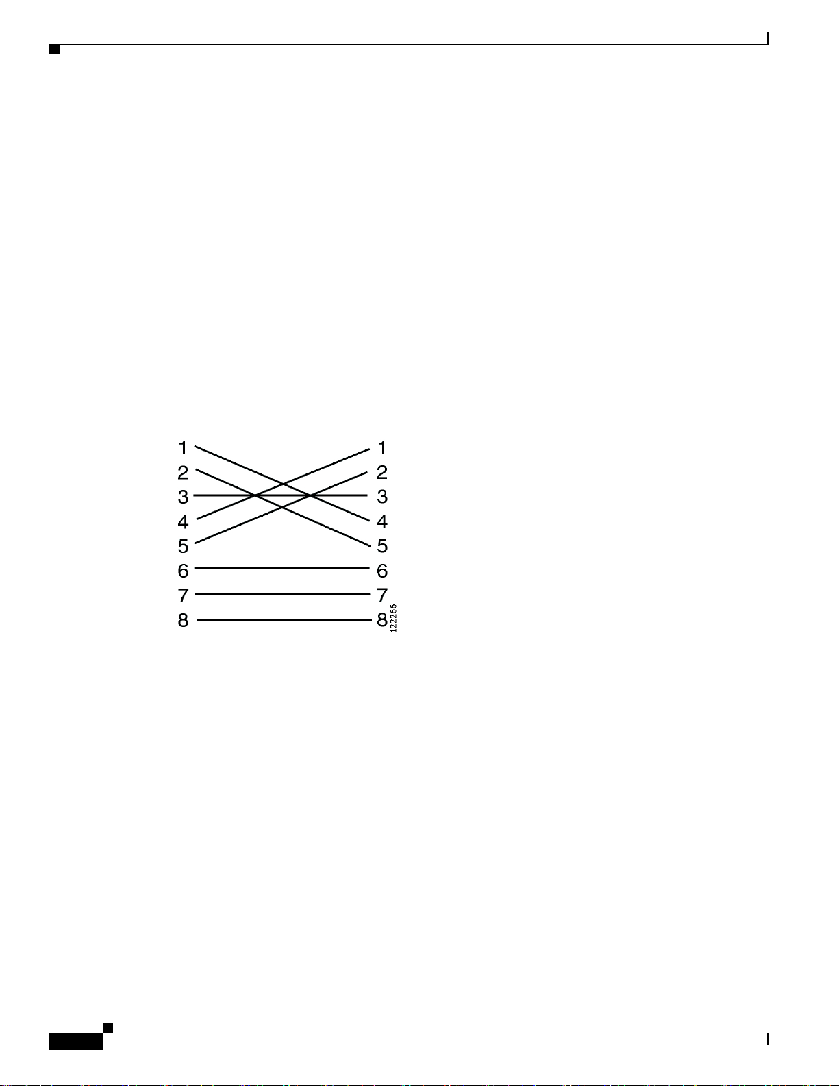
• Crossover cable for RJ-48 connectors. Cisco Systems provides this cable. See Figure 1-1.
Figure 1-1 Crossover-Cable Pinouts
Environmental Requirements for the Cisco Unified MeetingPlace 8106
The recommended operating temperature range for the Cisco Unified MeetingPlace 8106 is 50 to 95
degrees Fahrenheit with a noncondensing humidity of 5 to 80 percent.
It is essential to keep the Cisco Unified MeetingPlace 8106 equipment cool. The Cisco Unified
MeetingPlace 8106 has an internal fan assembly with four fans. To ensure that all Cisco Unified
MeetingPlace 8106 components are adequately cooled, the Cisco Unif ied Meeting Place 8106 must meet
the following requirements:
• At least 1.5 inches of clearance in the front and back of the Cisco Unified MeetingPlace 8106.
• At least 0.5 inches of clearance to the right and left of the Cisco Unified MeetingPlace 8106.
• At least 0.5 inches of clearance on the top and bottom of the Cisco Unified MeetingPlace 8106.
• Fill or cover all module slots (use filler panels in empty slots).
• Airflow in an open frame rack or in an enclosed cabinet must be from left to right.
Installation and Upgrade Guide for Cisco Unified MeetingPlace Audio Server 6.x
1-4
OL-13417-01
Page 15

Chapter 1 Preparing to Install the Cisco Unified MeetingPlace 8100 Series Hardware
Environmental Requirements for the Cisco Unified MeetingPlace 8112
Environmental Requirements for the Cisco Unified
MeetingPlace 8112
The recommended operating temperature range for the Cisco Unified MeetingPlace 8112 is 50 to 104
degrees Fahrenheit with a noncondensing humidity of 5 to 80 percent.
It is essential to keep the Cisco Unified MeetingPlace 8112 equipment cool. The Cisco Unified
MeetingPlace 8112 has three internal DC-powered fans. To ensure that all Cisco Unified
MeetingPlace
the following requirements:
• At least 24 inches of clearance in the back of the Cisco Unified MeetingPlace 8112.
• At least 1.75 inches of clearance on top of the Cisco Unified MeetingPlace 8112.
• Fill or cover all module slots (use filler panels in empty slots).
• Airflow in an open frame rack must be from front to back.
• Airflow in an enclosed cabinet must be from front to back and bottom to top.
8112 components are adequately cooled, the Cisco Unified MeetingPlace 8112 must meet
Power Requirements for the Cisco Unified MeetingPlace 8100 Series
Power for the Cisco Unified MeetingPlace 8100 series must come from a totally dedicated circuit
breaker within 8 feet of the equipment. In addition, the site must have additional power outlets for test
and maintenance equipmen t.
Do not plug any other electrical devices i nto an out let connected to the circuit breaker serving the Cisco
Unified MeetingPlace 8100 series.
Cisco Unified MeetingPlace 8106 requirements
• 100-240V
• 3 A
• 50/60 Hz
Cisco Unified MeetingPlace 8112 requirements
• 100-115/200-230V
• 6/3 A
• 50/60 Hz
If the power in your area is susceptible to fluctuations or interruptions, consider installing surge
suppressors or connecting the Cisco Unified MeetingPlace Audio Server system to an uninterruptible
power supply (UPS). If the Audio Server system loses power, it does not maintain its telephony
connections.
The Cisco Unified MeetingPlace 8106 draws a maximum of 300 watts of power and produces a
maximum of 1364 BTU per hour . The Cisco Unif ied MeetingPlace 8112 d raws a maximum of 60 0 watts
of power and produces a maximum of 2048 BTU per hour.
Table 1-1 lists the power requirements by country for the Cisco Unified MeetingPlace 8100 series.
OL-13417-01
Installation and Upgrade Guide for Cisco Unified MeetingPlace Audio Server 6. x
1-5
Page 16
Chapter 1 Preparing to Install the Cisco Unified MeetingPlace 8100 Series Hardware
T1 Digital Trunk Requirements for Cisco Unified MeetingPlace Systems
Tab l e 1-1 Power Requirements by Country for the Cisco Unified MeetingPlace 8100 Series
Country Power Socket
U.S.
Canada
Hong Kong
European Union
Japan 100 VAC
115 VAC NEMA 5-15R socket. Outlet installed within 8 feet of
the Audio Server.
240 VAC BS-1363 socket. Outlet installed within 8 feet of the
Audio Server.
NEMA 5-15R socket. Outlet installed within 8 feet of
(50 Hz for East Japan;
60 Hz for West Japan)
the Audio Server.
T1 Digital Trunk Requirements for Cisco Unified MeetingPlace
Systems
T1 Smart Blades support digital connections to a PBX system or to a public switched phone network
(PSTN). The framing for the digital lines can be either Extended Superframe (ESF) or D4 framing. The
digital lines can use either Binary 8-Zero Substitution (B8ZS) or jammed-bit coding.
We recommend using ESF framing and B8ZS coding. Using D4 framing or jammed-bit coding may not
be satisfactory.
Caution Supplemental earth grounding is required at all times. This supplemental grounding consists of a
grounding cable that is attached to supplemental ground lugs on the back of the Cisco Unified
MeetingPlace Audio Server chassis and is permanently connected to an earth ground point at the other
end through an appropriate facilities-grounding terminal.
You must use shielded cables, and you must electrically terminate the shield at the back of the Cisco
Unified MeetingPlace Audio Server.
Note the following considerations:
• Cisco Unified MeetingPlace supports fractional T1 services and h as complete fl e xi bilit y to act ivate
any or all ports on a span.
• Cisco Unified MeetingPlace can use dialed-number information to directly connect the caller to a
meeting or to determine the Cisco Unified MeetingPlace services to which the caller has access.
• You can configure Cisco Unified MeetingPlace to support devices where the T1 trunk does not
provide any signaling and is always offhook. This is used in applications where a clear channel
connection is required.
Table 1-2 lists the T1 digital trunk requirements by country for a Cisco Unified MeetingPlace system.
1-6
Installation and Upgrade Guide for Cisco Unified MeetingPlace Audio Server 6.x
OL-13417-01
Page 17
Chapter 1 Preparing to Install the Cisco Unified MeetingPlace 8100 Series Hardware
Tab l e 1-2 T1 Digital Trunk Req ui rements by Country
Country Requirements
U.S.
Canada
Hong Kong
Japan T1 connection into PBX with INS1500-to-T1 converter.
Public network to Channel Service Unit (CSU) connection—recEive and transMit
(E&M) wink start (line side and trunk side). Gr ound start or loo p start (line side
only).
U.S. only—FCC and CSA-listed CSU required.
Customer-supplied connectors—USOC (male) RJ-48 jacks. See the “Wiring
Requirements for Customer-Supplied Connectors—U.S., Canada, and
Hong Kong” section on page 1-9.
Cable provided by Cisco Systems—25-foot shielded twisted-pair cable with
ferrite.
PBX to CSU connection—FCC and CSA-listed CSU required fo r connections over
600 feet. The Cisco Unified MeetingPlace system ships with a 25-foot shielded
cable with ferrite beads for each T1 span. The cable terminates in an RJ-48
connector. Listed CSU is provided for overvoltage protection for the T1 Smart
Blades.
T1-Supported Protocols for Cisco Unified MeetingPlace Systems
Customer-supplied connectors—RJ-45 connector.
Cable provided by Cisco Systems—50-foot shielded cable (male-male). One per
T1 span.
Australia Cisco Systems does not supply any T1 cables with Cisco Unified MeetingP lace
Audio Server systems that are shipped to Australia.
In some cases, the cables that Cisco Systems provides may not be appropriate for your Private Branch
eXchange (PBX) or Network Interface Unit (NIU) side connections. If this is the case, create your own
custom cables.
Custom T1 CAS (channel-associated signaling) and IP cables require the following:
• Cat5e STP UTP cable with shielded RJ-45 connectors terminated to the cable shield at both ends.
• Add the ferrite that is on the ca ble supplied by Cisco Systems.
Caution (U.S. only) The FCC Part 68 registration number is EMC USA-34550-XD-T. Be sure to use only FCC
and CSA or UL-listed CSUs.
T1-Supported Protocols for Cisco Unified MeetingPlace
Systems
OL-13417-01
The following protocols are supported for T1 digital trunks:
• T1 CAS Cisco Unified MeetingPlace systems—E&M wink start, ground start, and loop start
• T1 PRI Cisco Unified MeetingPlace systems—AT&T (TR41459), Telcordia Technologies (NI-2),
and Nortel (DMS-100)
Installation and Upgrade Guide for Cisco Unified MeetingPlace Audio Server 6. x
1-7
Page 18
T1-Supported Protocols for Cisco Unified MeetingPlace Systems
T
End-to-end positive disconnect supervision is essential. Without it, Cisco Unified MeetingPlace cannot
reliably tell when a caller hangs up. Many PBX and central office systems can provide disconnect
signaling; we recommend E&M wink start lines because they provide for a positive answer and
disconnect supervision. In many cases, the person taking the order for the lines will not understand your
request, so you will probably need to escalate the request to someone with a technical background.
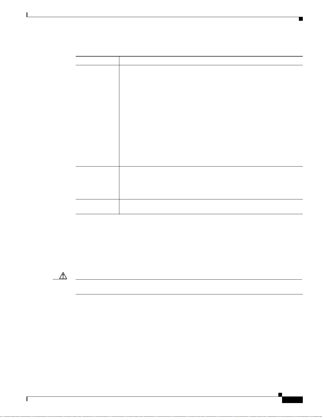
Figure 1-2 illustrates the Cisco Unified MeetingPlace digital telephony connections with T1 trunks.
Figure 1-2 Cisco Unified MeetingPlace Digital Connection Requirements—T1
Chapter 1 Preparing to Install the Cisco Unified MeetingPlace 8100 Series Hardware
PSTN
1 trunks
Channel
service unit
(CSU)
Customer-supplied
RJ-45 connectors
Special 23 ft cable
shipped with unit
T1 Smart Blade
PBX
T1 trunks
Cisco Unified MeetingPlace
Audio Server system
153998
Installation and Upgrade Guide for Cisco Unified MeetingPlace Audio Server 6.x
1-8
OL-13417-01
Page 19
Chapter 1 Preparing to Install the Cisco Unified MeetingPlace 8100 Series Hardware
Wiring Requirements for Customer-Supplied Connectors—U.S., Canada, and Hong Kong
Wiring Requirements for Customer-Supplied Connectors—U.S.,
Canada, and Hong
Table 1-3 and Table 1-4 describe wiring requirements for customer-supplied RJ-48 connectors.
Tab l e 1-3 Wiring of RJ-48 Connectors
Pin Name Description
1 T1 Cisco Unified MeetingPlace received signal - tip
2 R1 C isco Unified MeetingPla ce received signal - ring
4 T Cisco Unified MeetingPlace outgoing signal - tip
5 R Cisco Unified MeetingPlace outgoing signal - ring
To identify the pins, hold the RJ-48 connector as if you are going to plug it in with the tab down. Pin 1
is on the left.
If transmit and receive need to be reversed, also reverse the pins. See Table 1-4.
Tab l e 1-4 Wiring of RJ-48 Connectors When Transmit/Receive Is Reversed
Pin Name Description
1 T Cisco Unified MeetingPlace outgoing signal - tip
2 R Cisco Unified MeetingPlace outgoing signal - ring
4 T1 Cisco Unified MeetingPlace received signal - tip
5 R1 C isco Unified MeetingPla ce received signal - ring
Kong
Wiring Requirements for Customer-Supplied Connectors—U.K.,
Singapore, and India
For the E1 card, the connection from the network interface to the network can be one of the following
types:
• RJ-45connector.
• SMB coaxial connectors with SMB/BNC adapters.
Table 1-5 describes wiring requirements for customer-supplied RJ-45 connectors.
Tab l e 1-5 Wiring of RJ-45 Connectors
Pin Signal Description Direction
1 LRT Receive +ve (tip) Input
2 LRR Receive –ve (ring) Input
4 LTT Transmit +ve (tip) Output
5 LTR Transmit –ve (ring) Output
Installation and Upgrade Guide for Cisco Unified MeetingPlace Audio Server 6. x
OL-13417-01
1-9
Page 20

Chapter 1 Preparing to Install the Cisco Unified MeetingPlace 8100 Series Hardware
E1 Digital Trunk Requirements for Cisco Unified MeetingPlace Systems
E1 Digital Trunk Requirements for Cisco Unified MeetingPlace
Systems
Confirm that the E1 digital trunk specifications meet the requirements in Table 1-6.
Tab l e 1-6 E1 Digital Trunk Requirements
Country Requirements
European Union Connection Type—Euro ISDN and QSIG digital telephony (E1).
Cable supplied by Cisco Systems—25-foot Cat5 cable with RJ-48c connectors at
each end.
Socket—Connector must be an RJ-25 socket or an NBNC (female) connector.
Cable length (if you provide y our o wn cable)—Max imum cable lengt h is 328 feet.
Australia Cisco Systems does not supply any E1 cables with Cisco Unified MeetingPlace
Audio Server systems that are shipped to Australia.
In some cases, the RJ-48c cables that Cisco Systems provides may not be appropriate for your PBX or
NIU-side connections. If this is the case, create your own custom cables. Custom E1 and T1 PRI cables
require the following:
• Cat5e UTP cable.
• RJ-48c connector on the breakout box side.
• Add the ferrite that is on the cable that is supplied by Cisco Systems.
Note In E1 Cisco Unified MeetingPlace systems, you can connect Cisco Unified MeetingPlace directly to the
PSTN. You do not need a CSU.
E1-Supported Protocols for Cisco Unified MeetingPlace Systems
The following protocols are supported for E1 digital trunks:
• Euro-ISDN (ETSI 300-102).
• QSIG (ECMA version)—Channels are numbered 1 to 30.
• QSIG (ETSI version)—Channels are numbered 1 to 15 and 17 to 31.
The Cisco Unified MeetingPlace system supports only E1 PRI protocols. The Cisco Unified
MeetingPlace system does not support E1 CAS protocols.
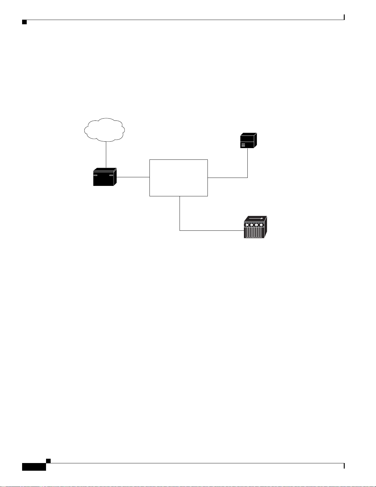
Figure 1-3 illustrates the Cisco Unified MeetingPlace digital telephony connections with E1 trunks.
1-10
Installation and Upgrade Guide for Cisco Unified MeetingPlace Audio Server 6.x
OL-13417-01
Page 21
Chapter 1 Preparing to Install the Cisco Unified MeetingPlace 8100 Series Hardware
E
153999
Figure 1-3 Cisco Unified MeetingPlace Digital Connection Requirements—E1
Modem Requirements for Cisco Unified MeetingPlace Systems
PSTN
1 Euro ISDN
Customer-supplied
RJ-45 connectors
Network
interface unit
(NIU)
Special 23 ft cable
shipped with unit
T1 Smart Blade
Cisco Unified MeetingPlace
PBX
E1 Euro ISDN
QSIG
Channel
service unit
(CSU)
(optional)
Audio Server system
Modem Requirements for Cisco Unified MeetingPlace Systems
The Cisco Unified MeetingPlace 8100 series includes an external modem that connects to the Cisco
Unified MeetingPlace system through a serial cable. Connect the modem cable from the back of the
Cisco Unified MeetingPlace 8100 series to the CPU transition module.
Confirm that you can call the modem extension from the outside so th at Cisco TAC can access the Cisco
Unified MeetingPlace system.
Table 1-7 lists modem requirements by country for a Cisco Unified MeetingPlace system.
Tab l e 1-7 Modem Requirements by Country
Country Requirements
U.S.
Canada
Hong Kong
• U.S. modem supplied by Cisco Systems.
• Serial cable.
• 6-foot modem cable.
• Customer-supplied standard analog phone jack (RJ-1 1). You must be able
to call the extension from the outside.
OL-13417-01
Installation and Upgrade Guide for Cisco Unified MeetingPlace Audio Server 6. x
1-11
Page 22
Chapter 1 Preparing to Install the Cisco Unified MeetingPlace 8100 Series Hardware
154000
M
r
e
LAN Requirements for Cisco Unified MeetingPlace Systems
Table 1-7 Modem Requirements by Country (continued)
Country Requirements
Japan • CE modem supplied by Cisco Systems.
• Serial cable.
• 8.2-foot modem cable.
• Customer-supplied standard analog phone jack (RJ-1 1). You must be able
to call the extension from the outside.
European Union • Global modem supplied by Cisco Systems.
• Serial cable.
• Customer-supplied standard analog phone jack (RJ-1 1). You must be able
to call the extension from the outside.
LAN Requirements for Cisco Unified MeetingPlace Systems
To connect to other applications, such as MeetingTime and Cisco Unified MeetingPlace Web
Conferencing, Cisco Unified MeetingPlace Audio Server systems require certain TCP and User
Datagram Protocol (UDP) ports to remain open on your network.
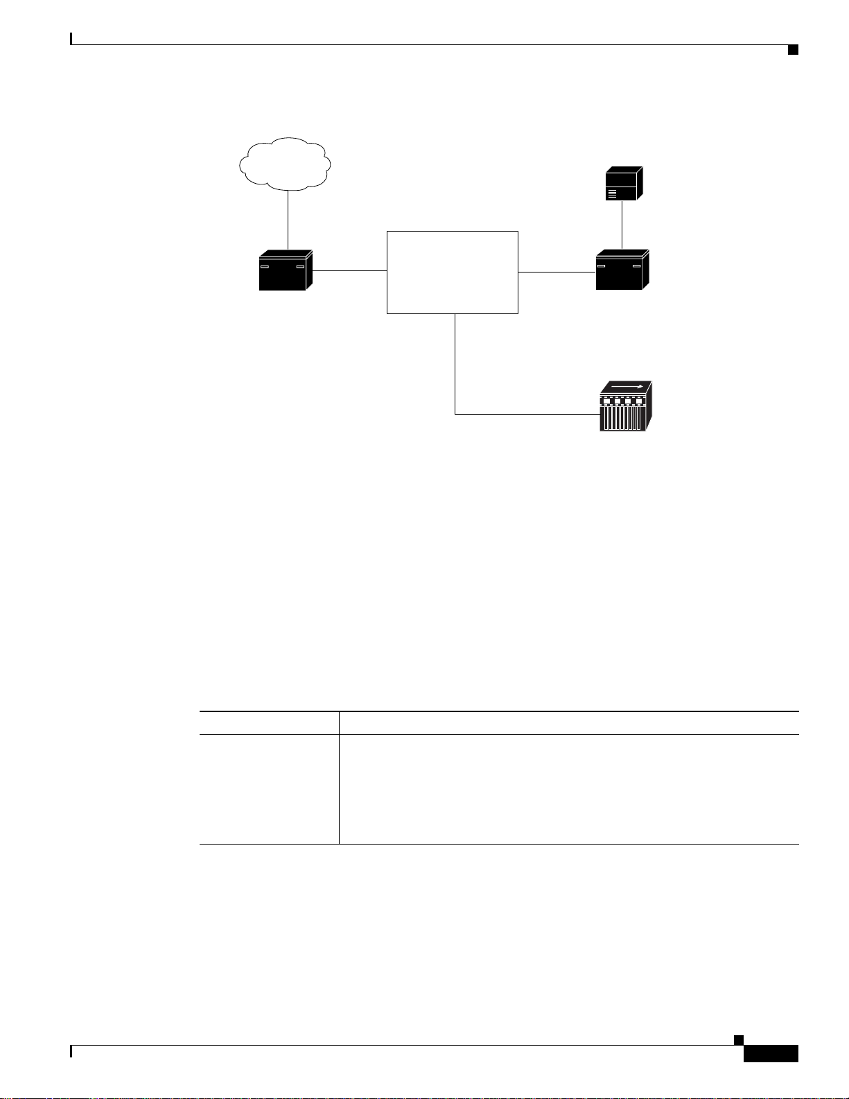
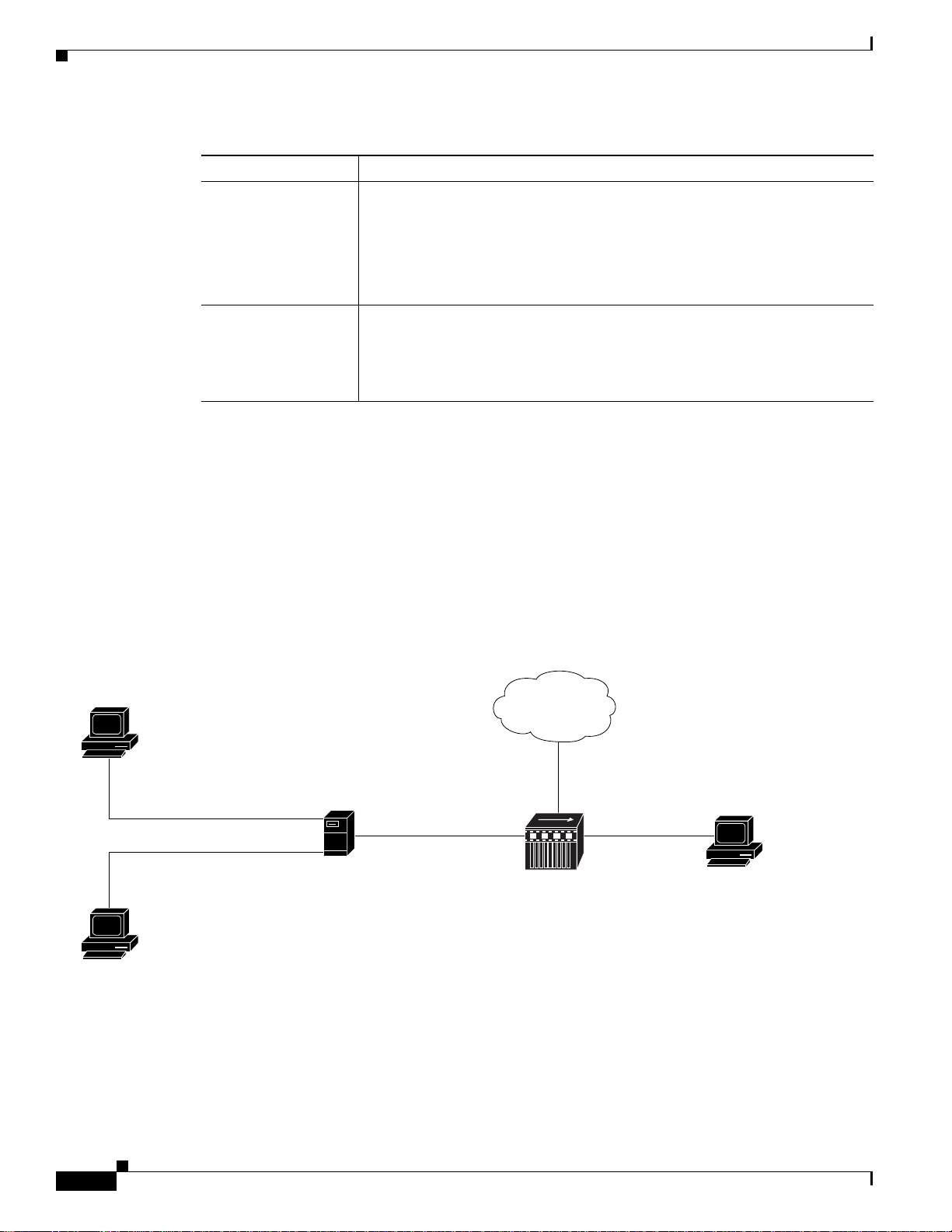
Figure 1-4 illustrates the ports that a Cisco Unified MeetingPlace system uses for communication.
Unless otherwise specified, all ports listed are TCP.
Figure 1-4 TCP/UDP Port Requirements
End user
heduling via web,
icrosoft Outlook,
r IBM Lotus Notes
80
80 or 443(SSL) and 1627
1503 (NetMeeting)
Microsoft Windows NT
system with
Cisco Unified MeetingPlace
integration applications
5001, 5003, 5005
Cisco Unified MeetingPlace
Network
time protocol
server
UDP 123
Audio Server system
5001, 5005
System manage
using MeetingTim
End user in a
eb conference
1-12
Ensure that the Cisco Unified MeetingPlace Audio Server system resides on a network segment that is
free from potential network problems, such as storms, loops, and collisions.
Installation and Upgrade Guide for Cisco Unified MeetingPlace Audio Server 6.x
OL-13417-01
Page 23

Chapter 1 Preparing to Install the Cisco Unified MeetingPlace 8100 Series Hardware
LAN Cable Requirements for Cisco Unified MeetingPlace Systems
LAN Cable Requirements for Cisco Unified MeetingPlace
Systems
The Cisco Unified MeetingPlace Audio Server system attaches to an Ethernet LAN, which pr ovides all
the communication from the Audio Server sy stem to yo ur netw ork. There are tw o possible scenarios for
using an Ethernet LAN cable:
• Connecting from an Audio Server CPU to your network.
• Connecting from an Audio Server Multi Access Blade to your network (for IP ports only).
For all configurations, you need a customer-supplied LAN cable to connect the Audio Server CPU to
your network.
For IP configurations, Cisco Systems supplies the necessary LAN cables to connect the Multi Access
Blade that is used for the IP configuration to your network.
Table 1-8 lists the LAN cable requirements by country for a Cisco Unified MeetingPlace system.
Tab l e 1-8 LAN Cable Requirements by Country
Country Requirements
U.S.
Canada
Hong Kong
Japan CPU to LAN cable—For twisted-pair Ethernet, 100BASE-TX UTP. You need to
Australia Cisco Systems does not supply any LAN cables with Cisco Unified MeetingPlace
CPU to LAN cable—For twisted-pair Ethernet, 100BASE-TX. You need to
supply an RJ-45 connector.
10BASET works but is not recommended.
Multi Access Blade to LAN cable—For twisted-pair Ethernet, Cat5e. You need
an RJ-45 connector. Cisco Systems provides a 25-foot CAT-5e cable
(#3300-0029-02) with a Ferrite snap-on bead on one end. If yo u change the cab le,
you must move the snap-on bead.
Note You must set the Ethernet switch port (or any other network devices) to
which the Multi Access Blade connects directly to fixed 100BASE-TX
Full Duplex. Otherwise, you may experience decreased voice quality.
supply an RJ-45 connector.
10BASET works but is not recommended.
Multi Access Blade to LAN cable—For twisted-pair Ethernet, Cat5e. You need
an RJ-45 connector. Cisco Systems provides a 25-foot Cat5e cable
(#3300-0029-02) with a Ferrite snap-on bead on one end. If yo u change the cab le,
you must move the snap-on bead.
Note You must set the Ethernet switch port (or any other network devices) to
which the Multi Access Blade connects directly to fixed 100BASE-TX
Full Duplex. Otherwise, you may experience decreased voice quality.
Audio Server systems that are shipped to Australia.
OL-13417-01
Installation and Upgrade Guide for Cisco Unified MeetingPlace Audio Server 6. x
1-13
Page 24

LAN Cable Requirements for Cisco Unified MeetingPlace Systems
Chapter 1 Preparing to Install the Cisco Unified MeetingPlace 8100 Series Hardware
1-14
Installation and Upgrade Guide for Cisco Unified MeetingPlace Audio Server 6.x
OL-13417-01
Page 25

CHAPTER
2
Installing the Cisco Unified MeetingPlace 8100 Series Hardware
This chapter contains the following sections:
• Contents of Shipped Boxes for the Cisco Unified MeetingPlace Audio Server System, page 2-1
• Mounting the Cisco Unified MeetingPlace 8100 Series, page 2-3
• Connecting the Cables to the Cisco Unified MeetingPlace 8100 Series, page 2-10
• About Telephony Configurations for E1 and T1 PRI Cisco Unified MeetingPlace Systems,
page 2-15
• About Telephony Configurations for IP Cisco Unified MeetingPlace Systems, page 2-27
• About Telephony Configurations for Mixed Cisco Unified MeetingPlace Systems, page 2-30
• Installing and Connecting the Modem, page 2-36
Contents of Shipped Boxes for the Cisco Unified MeetingPlace Audio Server System
All Cisco Unified MeetingPlace Audio Server systems ship in two boxes. One box contains the Cisco
Unified MeetingPlace Audio Server and its accessories. The other box contains the telephony cables,
modem and modem cables, and the breakout box and cables, if applicable.
Cisco Systems provides the correct number of telephony cables for the Cisco Unified MeetingPlace
system:
• The number of IP LAN cables that you receive depends on the number of ports that were purchased
for the Cisco Unified MeetingPlace system. You receive one IP LAN cable for every Multi Access
Blade in the Cisco Unified MeetingPlace system.
• The number of T1 CAS telephony cables that you receive depends on the number of ports that were
purchased for the Cisco Unified MeetingPlace system. You receive one T1 CAS telephony cable for
every 24 PSTN ports being activated.
OL-13417-01
Installation and Upgrade Guide for Cisco Unified MeetingPlace Audio Server 6. x
2-1
Page 26

Chapter 2 Installing the Cisco Unified MeetingPlace 8100 Series Hardware
Contents of Shipped Boxes for the Cisco Unified MeetingPlace Audio Server System
• The number of E1 telephony cables that you receive depends on the number of Multi Access Blades
that were purchased for the Cisco Unified MeetingPlace system. You receive 16 cables with each
Multi Access Blade.
• The number of T1 PRI telephony cables that you receive depends on the number of Multi Access
Blades that were purchased for the Cisco Unified MeetingPlace system. You receive 16 cables with
each Multi Access Blade MP-MA-16-PRI and four cables with each Multi Access Blade
MP-MA-4-PRI.
The following items are also included in the boxes:
• The Cisco Unified MeetingPlace 8100 series server. Visually inspec t the se rver for damage. If it is
damaged or scratched, contact Cisco
T A C. (See the “Obtaining Documentation, Obta ining Support,
and Security Guidelines” section on page x.)
Cisco Unified MeetingPlace Audio Server software is installed on the Cisco Unified MeetingPlace
8100 series server in manuf acturing, so you do not need to install Au dio Server softw are. The server
should already be configured with the correct cards and transition modules as well. If it is not,
contact Cisco
Caution The Cisco Unified MeetingPlace 8106, its peripheries, and the packing materi als can we igh up to 7 5 lbs
(34 kg).
TAC.
The Cisco Unified MeetingPlace 8112, its peripherals, and the packing materials can weigh up to 130
lbs (59 kg).
• Two sets of mounting hardware to mount the Cisco Unified MeetingPlace Audio Server onto the
rack:
–
Screws for the Cisco Unified MeetingPlace 8106.
–
Rack-mount rails with 18 Ph illips -head sc rews for the Cisco U nified Meeting Place 811 2.
• Small Computer System Interface (SCSI) cable (Cisco Unified MeetingPlace 8112 only).
• Cross ove r c a b le .
• Power cable.
• External modem and cables (modem power cable, modem cable, and phone extension cable).
• IP LAN cables for Multi Access Blades, for Cisco Unified MeetingPlace systems using IP ports.
These IP LAN cables connect the Multi Access Blade to your LAN.
• T1 CAS telephony cables for T1 Smart Blades, for Cisco Unified MeetingPlace systems using T1
CAS ports. These T1 CAS telephony cables connect the T1 Smart Blades to the Cisco Unified
MeetingPlace system.
• E1 telephony cables, for Cisco Unified MeetingPlace systems using E1 ports. These E1 telephony
cables connect the front of the breakout box to the Cisco Unified MeetingPlace system.
• T1 PRI telephony cables, for Cisco Unif ied MeetingPlace systems using T1 PRI ports. These T1 PRI
telephony cables connect the front of the breakout box to the Cisco Unified Meeti ngPlace sy stem.
• Applicable software, manuals, and license documents.
In addition, Cisco Systems ships the follo wing items with Cisco Unified MeetingPlace sy stems requiring
a breakout box (T1 PRI or E1 configuration):
2-2
• Breakout box.
• Screws for mounting the breakout box.
Installation and Upgrade Guide for Cisco Unified MeetingPlace Audio Server 6.x
OL-13417-01
Page 27

Chapter 2 Installing the Cisco Unified MeetingPlace 8100 Series Hardware
Mounting the Cisco Unified MeetingPlace 8100 Series
• Trunk card interface cable assemblies (50-pin Amphenol cables). The number of trunk card
interface cable assemblies that you receive depends on how many and the type of Multi Access
Blades in the Cisco Unified MeetingPlace system. Cisco Systems ships two cables with each
MP-MA-16-PRI and one cable with each MP-MA-4-PRI.
Mounting the Cisco Unified MeetingPlace 8100 Series
Before mounting the Cisco Unified MeetingPlace Audio Server in a rack, confirm that you have met all
the requirements in the
on page 1-4 or the “Environmental Requirements for the Cisco Unified MeetingPlace 8112” section on
page 1-5.
The Cisco Unified MeetingPlace 8100 series servers can be mounted in two types of racks:
“Environmental Requirements for the Cisco Unif ied MeetingPlace 8106” section
Cisco Unified MeetingPlace 8106
Cisco Unified MeetingPlace 8112
When mounting the Cisco Unified MeetingPlace A udio Server in a Frame-Relay rack, which is common
in central office locations, the Cisco Unified MeetingPlace 8106 is held along the front of the chassis
and the Cisco Unified MeetingPlace 8112 is held along the center of the chassis.
After mounting the Cisco Unified MeetingPlace Audio Server, mount the breakout box, if applicable.
See the
on page 2-7.
“Mounting the Breakout Box for T1 PRI and E1 Cisco Un ified MeetingPlac e Systems” section
• 19-inch Frame-Relay rack.
See the “Mounting the Cisco Unified MeetingPlace 8106 in a
19-Inch Frame-Relay Rack” section on page 2-3.
• 19-inch Electronic Industries Alliance (EIA) equipment rack.
See the “Mounting the Cisco Unified MeetingPlace 8106 in a
19-Inch EIA Equipment Rack” section on page 2-5.
• 19- or 23-inch Frame-Relay rack.
See the “Mounting the Cisco Unified MeetingPlace 8112 in a
19- or 23-Inch Frame-Relay Rack” section on page 2-4.
• 19- or 23-inch Electronic Industries Alliance (EIA) equi pment
rack.
See the “Mounting the Cisco Unified MeetingPlace 8112 i nto a
19- or 23-Inch EIA Equipment Rack” section on page 2-6.
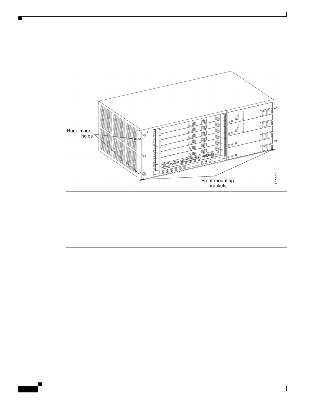
Mounting the Cisco Unified MeetingPlace 8106 in a 19-Inch Frame-Relay Rack
The Cisco Unified MeetingPlace 8106 ships with tw o mounting bracket s already attached to the front of
it (see
Figure 2-1). The long sides of the brackets are fastened to the Cisco Unified MeetingPlace 8106.
To Mount the Cisco Unified MeetingPlace 8106 in a 19-Inch Frame-Relay Rack
Step 1 Slide the Cisco Unified MeetingPlace 8106 into the front of the rack.
Installation and Upgrade Guide for Cisco Unified MeetingPlace Audio Server 6. x
OL-13417-01
2-3
Page 28
Mounting the Cisco Unified MeetingPlace 8100 Series
Step 2 Attach the Cisco Unified MeetingPlace 8106 to the rack. The Cisco Unified MeetingPlace 8106 comes
with screws to attach the mounting brackets to the rack. See
Figure 2-1 Mounting the Cisco Unified MeetingPlace 8106 in a Frame-Relay Rack
Chapter 2 Installing the Cisco Unified MeetingPlace 8100 Series Hardware
Figure 2-1.
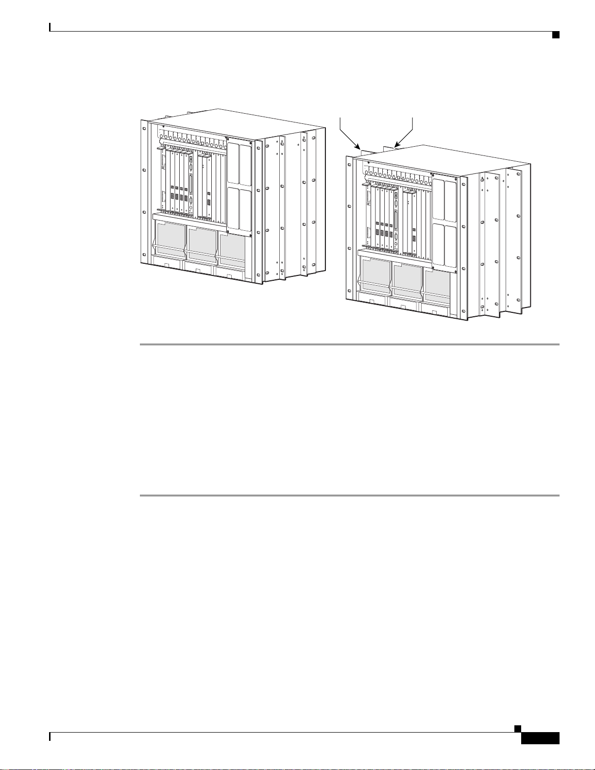
Mounting the Cisco Unified MeetingPlace 8112 in a 19- or 23-Inch Frame-Relay Rack
To Mount the Cisco Unified MeetingPlace 8112 in a 19- or 23-Inch Frame-Relay Rack
Step 1 Attach two mounting br acke ts to the front mount ing holes of the Cisco Unified MeetingPlace 8112. See
Figure 2-2 below.
• For 19-inch racks, fasten the long side of the bracket to the Cisco Unified MeetingPlace 8112.
• For 23-inch racks, fasten the short side of the bracket to the Cisco Unified MeetingPlace 8112.
Step 2 Slide the Cisco Unified MeetingPlace 8112 into the front of the rack.
Step 3 Attach the Cisco Unified MeetingPlace 8112 to the rack and secure it by using the eight Phillips-head
screws that shipped with the Cisco Unified MeetingPlace 8112.
Step 4 Attach two mounting brackets to the rear mounting holes of the Cisco Unified MeetingPlace 8112. See
Figure 2-2 below.
• For 19-inch racks, fasten the long side of the bracket to the Cisco Unified MeetingPlace 8112.
• For 23-inch racks, fasten the short side of the bracket to the Cisco Unified MeetingPlace 8112.
Step 5 Secure the rear mounting bracket to the rack with the eight Phillips-head screws that shipped with the
Cisco Unified MeetingPlace 8112.
2-4
Installation and Upgrade Guide for Cisco Unified MeetingPlace Audio Server 6.x
OL-13417-01
Page 29
Chapter 2 Installing the Cisco Unified MeetingPlace 8100 Series Hardware
Rear-mounting
Front-mounting
For 23-inch installation
Figure 2-2 Mounting the Cisco Unified MeetingPlace 8112 in a Frame-Relay Rack
Mounting the Cisco Unified MeetingPlace 8100 Series
brackets
OUT OF
OUT OF
SERVICE
OUT OF
SERVICE
OUT OF
OUT OF
SERVICE
OUT OF
SERVICE
OUT OF
SERVICE
OUT OF
SERVICE
OUT OF
SERVICE
OUT OF
SERVICE
OUT OF
SERVICE
OUT OF
SERVICE
OUT OF
SERVICE
OUT OF
SERVICE
1
2
1
2
3
4
5
6
7
8
1
2
9
10
11
12
13
14
15
16
OUT OF
SERVICE
OUT OF
SERVICE
OUT OF
SERVICE
OUT OF
SERVICE
3
4
1
2
1
2
3
4
OUT OF
SERVICE
OUT OF
SERVICE
OUT OF
SERVICE
OUT OF
SERVICE
5
6
1
1
2
2
1
1
2
2
3
3
4
4
1
2
1
2
3
4
7
89
OUT OF
SERVICE
OUT OF
SERVICE
OUT OF
SERVICE
OUT OF
SERVICE
OUT OF
SERVICE
OUT OF
SERVICE
OUT OF
SERVICE
OUT OF
SERVICE
SERVICE
OUT OF
SERVICE
10
OUT OF
SERVICE
11
SERVICE
12
13
14
15
16
PWR ON
PWR OFF
1
2
1
2
3
4
OUT OF
SERVICE
OUT OF
SERVICE
1
1
2
3
4
5
6
7
8
1
2
9
10
11
12
13
14
15
16
brackets
OUT OF
OUT OF
SERVICE
OUT OF
SERVICE
OUT OF
OUT OF
SERVICE
OUT OF
SERVICE
OUT OF
SERVICE
OUT OF
SERVICE
OUT OF
SERVICE
OUT OF
SERVICE
OUT OF
SERVICE
OUT OF
SERVICE
OUT OF
SERVICE
OUT OF
SERVICE
2
3
OUT OF
SERVICE
OUT OF
SERVICE
OUT OF
SERVICE
OUT OF
SERVICE
4
5
1
1
2
2
1
1
2
2
3
3
4
4
OUT OF
SERVICE
OUT OF
SERVICE
OUT OF
SERVICE
OUT OF
SERVICE
6
7
1
1
2
2
1
1
2
2
3
3
4
4
89
OUT OF
SERVICE
OUT OF
SERVICE
OUT OF
SERVICE
OUT OF
SERVICE
OUT OF
SERVICE
OUT OF
SERVICE
SERVICE
OUT OF
SERVICE
10
OUT OF
SERVICE
11
SERVICE
12
13
14
15
16
PWR ON
PWR OFF
1
2
1
2
3
4
For 19-inch installation
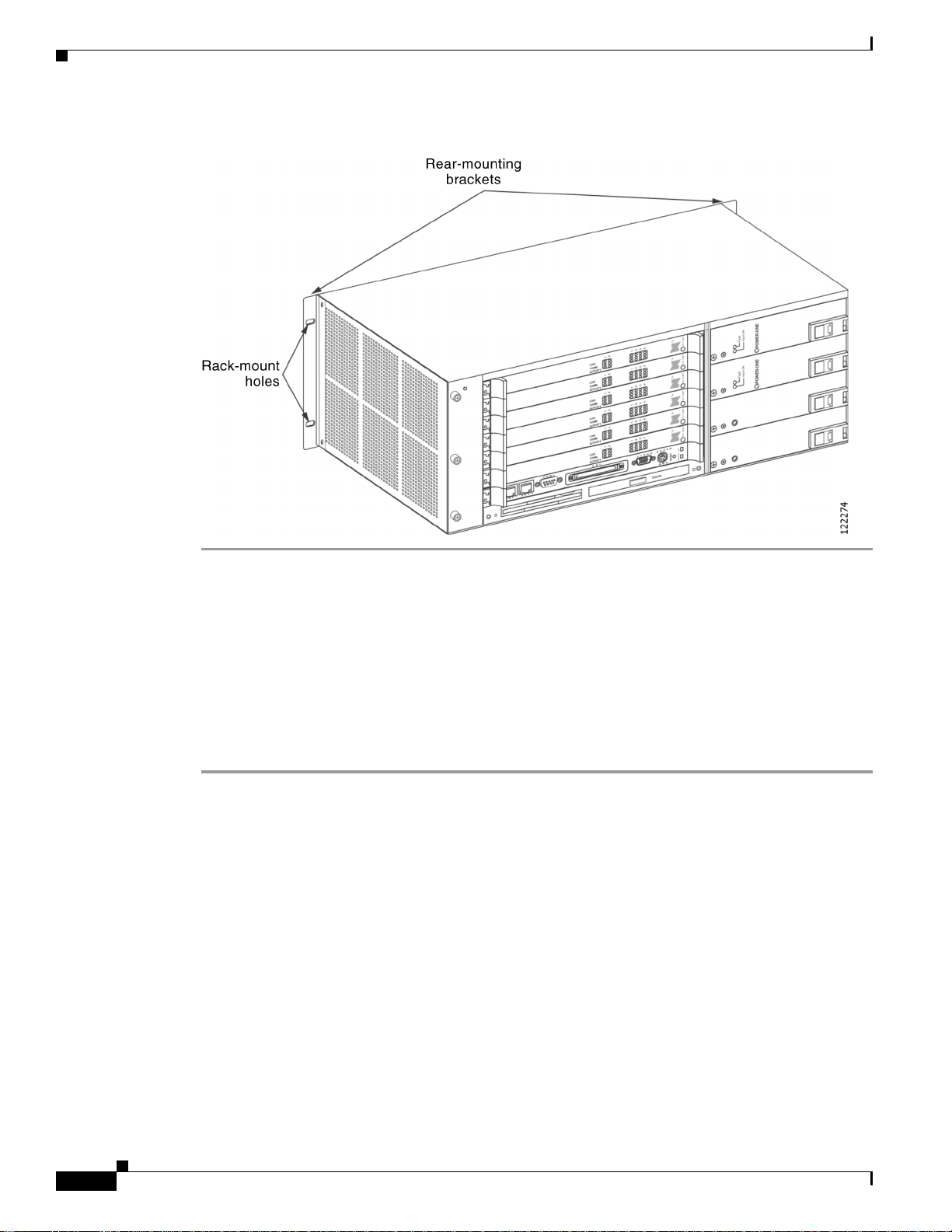
Mounting the Cisco Unified MeetingPlace 8106 in a 19-Inch EIA Equipment
92343
Rack
In a 19-inch EIA equipment rack, you mount the Cisco Unified MeetingPlace 8106 on the back rails.
The Cisco Unified MeetingPlace 8106 ships with two mounting brackets already attached to the front
(see
Figure 2-3).
To Mount the Cisco Unified MeetingPlace 8106 in a 19-Inch EIA Equipment Rack
Step 1 To remove the mounting brackets from the front of the Cisco Unified MeetingPlace 8106 and attach
them to the back, remove the two screws on each side of the back of the Cisco Unified MeetingPlace
8106 (four total) and put them aside.
Step 2 Remove the screws that secure the mounting brackets to the front of the Cisco Unified MeetingPlace
8106 (two on each side).
Step 3 Attach the brackets to the back of the Cisco Unified MeetingPlace 8106 by using the screws that were
originally used to attach the brackets to the front (two on each side).
Step 4 Reattach the screws removed from the back of the Cisco Unified MeetingPlace 8106 to the holes in the
front (where the brackets were originally attached to the front). The brackets are now rear-mounted.
Step 5 Slide the Cisco Unified MeetingPlace 8106 into the rack.
Step 6 Attach the Cisco Unified MeetingPlace 8106 mounting brackets to the rack.
OL-13417-01
Installation and Upgrade Guide for Cisco Unified MeetingPlace Audio Server 6. x
2-5
Page 30
Mounting the Cisco Unified MeetingPlace 8100 Series
Figure 2-3 Mounting the Cisco Unified MeetingPlace 8106 in an EIA Equipment Rack
Chapter 2 Installing the Cisco Unified MeetingPlace 8100 Series Hardware
Mounting the Cisco Unified MeetingPlace 8112 into a 19- or 23-Inch EIA Equipment Rack
In a 19- or 23-inch EIA equipment rack, you mount the Cisco Unified MeetingPlace 8112 on the front
rails.
To Mount the Cisco Unified MeetingPlace 8112 into a 19- or 23-Inch EIA Equipment Rack
Step 1 If you are installing the Cisco Unified MeetingPlace 8112 in a 19-inch rack, you do not need any
additional mounting equipment. Skip to
If you are installing the Cisco Unified MeetingPlace 8112 in a 23-inch rack, you must obtain extension
brackets from the rack manufacturer. Install the optional extender brackets as described by the rack
manufacturer.
Step 2 Slide the Cisco Unified MeetingPlace 8112 into the front of the rack.
Step 3 Attach the Cisco Unified Meet ingPlace 8112 to the rack with the eight Ph illips-head scre ws that shipped
with the Cisco Unified MeetingPlace 8112. See
Step 2.
Figure 2-4.
2-6
Installation and Upgrade Guide for Cisco Unified MeetingPlace Audio Server 6.x
OL-13417-01
Page 31

Chapter 2 Installing the Cisco Unified MeetingPlace 8100 Series Hardware
Figure 2-4 Mounting the Cisco Unified MeetingPlace 8112 into an EIA Equipment Rack
Rack-mounting
holes
OUT OF
OUT OF
SERVICE
OUT OF
SERVICE
OUT OF
OUT OF
SERVICE
OUT OF
SERVICE
OUT OF
SERVICE
OUT OF
SERVICE
OUT OF
SERVICE
OUT OF
SERVICE
OUT OF
SERVICE
OUT OF
SERVICE
OUT OF
SERVICE
OUT OF
SERVICE
1
2
1
2
3
4
5
6
7
8
1
2
9
10
11
12
13
14
15
16
OUT OF
SERVICE
OUT OF
SERVICE
OUT OF
SERVICE
OUT OF
SERVICE
3
4
1
2
1
2
3
4
OUT OF
SERVICE
OUT OF
SERVICE
OUT OF
SERVICE
OUT OF
SERVICE
5
6
1
1
2
2
1
1
2
2
3
3
4
4
OUT OF
SERVICE
OUT OF
SERVICE
OUT OF
SERVICE
OUT OF
SERVICE
7
89
1
2
1
2
3
4
OUT OF
SERVICE
OUT OF
SERVICE
OUT OF
SERVICE
OUT OF
SERVICE
SERVICE
OUT OF
SERVICE
10
OUT OF
SERVICE
11
SERVICE
12
13
14
15
16
PWR ON
PWR OFF
1
2
1
2
3
4
Mounting the Cisco Unified MeetingPlace 8100 Series
92344
Mounting the Breakout Box for T1 PRI and E1 Cisco Unified MeetingPlace Systems
Note If the Cisco Unified MeetingPlace system does not require a breakout box (T1 PRI or E1 conf iguration) ,
skip to the
page 2-11.
The breakout box provides a standard RJ-45 telephony interface. The breakout box interfaces to a
maximum of 16 cables with an MP-MA-16-PRI and a maximum of 4 cables with each MP-MA-4-PRI.
Cisco Systems ships the necessary number of RJ-48c cables to connect each breakout box to your PBX
or Telco NIU with each Multi Access Blade.
Note In some cases, the RJ-48c cables provided by Cisco Systems may not be appropria te for you r PBX or
NIU side connections. If this is the case, create your own custom cables, which require an RJ-48c
connector on the breakout box side. (For custom-cable requirements, see the
Requirements for Cisco Unified MeetingPla ce Systems” se ction on page 1-10.)
Cisco Systems also ships the necessary number of 50-pin Amphenol cables with the breakout box: two
50-pin Amphenol cables to connect each MP-MA-16-PRI to the break out box and one 50-pin Amphenol
cable to connect each MP-MA-4-PRI to the breakout box.
If the Cisco Unified MeetingPlace system requires two MP-MA-16-PRIs, you need two breakout boxes.
(A fully loaded 960-port E1 Cisco Unified MeetingPlace system and a fully loaded 736-port T1 PRI
Cisco Unified MeetingPlace system have two MP-MA-16-PRIs.)
“Connecting the Power Cable to the Cisco Unified MeetingPlace 8100 Series” section on
“E1 Digital Trunk
OL-13417-01
Note Only the Cisco Unified MeetingPlace 8112 can have two breakout boxes.
Installation and Upgrade Guide for Cisco Unified MeetingPlace Audio Server 6. x
2-7
Page 32

Mounting the Cisco Unified MeetingPlace 8100 Series
To Mount the Breakout Box for a T1 PRI or E1 Cisco Unified MeetingPlace System
Step 1 Locate the breakout box that shipped with the Cisco Unified MeetingPlace Audio Server.
Step 2 Locate the screws for mounting the breakout box that came with the Cisco Unified MeetingPlace Audio
Server.
Step 3 Use a screwdriver to mount the breakout box in the position directly above the Cisco Unified
MeetingPlace Audio Server in the rack, as shown in the applicable figure:
Chapter 2 Installing the Cisco Unified MeetingPlace 8100 Series Hardware
Cisco Unified MeetingPlace 8106
Cisco Unified MeetingPlace 8112
Step 4 If applicable, mount the seco nd br eak ou t box by repeating Step 2 and Step 3. Place the second breakout
See Figure 2-5.
See Figure 2-6.
box directly above the first breakout box. See Figure 2-7.
Figure 2-5 Mounting the Breakout Box for a Cisco Unified MeetingPlace 8106
2-8
Installation and Upgrade Guide for Cisco Unified MeetingPlace Audio Server 6.x
OL-13417-01
Page 33

Chapter 2 Installing the Cisco Unified MeetingPlace 8100 Series Hardware
Figure 2-6 Mounting the Breako ut Box for a Cisco Unified MeetingPlace 8112
Mounting the Cisco Unified MeetingPlace 8100 Series
OL-13417-01
Installation and Upgrade Guide for Cisco Unified MeetingPlace Audio Server 6. x
2-9
Page 34

Connecting the Cables to the Cisco Unified MeetingPlace 8100 Series
Figure 2-7 Mounting Two Breakout Boxes for a Cisco Unified MeetingPlace 8112
Chapter 2 Installing the Cisco Unified MeetingPlace 8100 Series Hardware
Connecting the Cables to the Cisco Unified MeetingPlace
8100
Series
This section contains the following information:
• Connecting the Power Cable to the Cisco Unified MeetingPlace 8100 Series, page 2-11
• Connecting the SCSI Cable to the Cisco Unified MeetingPlace 8112, page 2-11
• Connecting the LAN Cable to the Cisco Unified MeetingPlace 8100 Series, page 2-11
• Connecting T1 CAS Telephony Cables for a Cisco Unified MeetingPlace 8106, page 2-12
• Connecting T1 CAS Telephony Cables for a Cisco Unified MeetingPlace 8112, page 2-13
Installation and Upgrade Guide for Cisco Unified MeetingPlace Audio Server 6.x
2-10
OL-13417-01
Page 35

Chapter 2 Installing the Cisco Unified MeetingPlace 8100 Series Hardware
Connecting the Cables to the Cisco Unified MeetingPlace 8100 Se ries
Connecting the Power Cable to the Cisco Unified MeetingPlace 8100 Series
Warning
Warning
Step 1 Locate the power cable that shipped with the Cisco Unified MeetingPlace Audi o Server.
Step 2 Attach the socket end of the power cable to the AC inlet on the back of the Cisco Unified MeetingPlace
This equipment must be grounded. Never defeat the ground conductor or operate the equipment in the
absence of a suitably installed ground conductor. Contact the appropriate electrical inspection
authority or an electrician if you are uncertain that suitable grounding is available.
When installing or replacing the unit, the ground connection must always be made first and
disconnected last.
To Connect the Power Cable to the Cisco Unified MeetingPlace 8100 Series
Statement 1046
Audio Server.
Step 3 Plug the other end of the power cable into the AC power source.
Connecting the SCSI Cable to the Cisco Unified MeetingPlace 8112
Note The Cisco Unified MeetingPlace 8106 does not have a SCSI cable.
Statement 1024
To Connect the SCSI Cable to the Cisco Unified MeetingPlace 8112
Step 1 Confirm that the power switch on the Cisco Unified MeetingPlace 8112 is set to off (“O”).
Step 2 Attach one end of the SCSI cable that came with the Cisco Unified MeetingPlace Audio Server system
to the SCSI connector on the back of the floppy-drive housing.
Step 3 Attach the other end of the SCSI cable to the SCSI port on the CPU transition module in slot 7 on the
back of the Cisco Unified MeetingPlace 8112.
Connecting the LAN Cable to the Cisco Unified MeetingPlace 8100 Series
Y ou must supp ly the LAN cable to connect the Cisco Unifi ed MeetingPlace Audio Server to the network.
See the
that you have the correct LAN cable and connector.
To Connect the LAN Cable to the Cisco Unified MeetingPlace 8100 Series
Step 1 Locate the LAN cable.
Step 2 Plug one end of the LAN cable into the LAN socket.
“LAN Requirements for Cisco Unified MeetingPlace Systems” sectio n on pag e 1-12 to conf ir m
OL-13417-01
Installation and Upgrade Guide for Cisco Unified MeetingPlace Audio Server 6. x
2-11
Page 36

Chapter 2 Installing the Cisco Unified MeetingPlace 8100 Series Hardware
Connecting the Cables to the Cisco Unified MeetingPlace 8100 Series
Step 3 Plug the other end of the LAN cable into Ethernet connection 1 on the CPU transition module that is
located in the back of the Cisco Unified MeetingPlace Audio Server.
Connecting T1 CAS Telephony Cables for a Cisco Unified MeetingPlace 8106
Each T1 Smart Blade transition module has connectors for four trunk lines in the back of the Cisco
Unified MeetingPlace Audio Server.
Looking at the back of the Cisco Unified MeetingPlace 8106, the T1 Smart Blade transition modules
begin in slot 1 on the bottom and mov e up to the t op. The cables go from ri ght to left on the bot tom slot,
then from right to left on the second most bottom slot, and so on up to the top slot, where they continue
going from right to left.
Table 2-1 shows the order in which the cables should be placed.
Tab l e 2-1 Cable Locations in the Cisco Unified MeetingPlace 8106
Connector Connector Connector Connector
Slot 6
Slot 5
Slot 4
Slot 3
Slot 2
Slot 1
24 23 22 21
20 19 18 17
16 15 14 13
12 11 10 9
8 7 6 5
4 3 2 1
The number of T1 CAS telephony cables that Cisco Sy stems ships with the Cisco Un if ied MeetingPlace
system depends on the number of po rts being a ctivated. Cisco Systems ships one T1 CA S telephony
cable for every 24 ports.
Figure 2-8 shows the cable connections for a Cisco Unified Meet ingPlace 8106 with 576 T1 CAS po rts.
Four T1 CAS telephony cables connect to each of the six T1 Smart Blade transition modules for a total
of 24 T1 CAS telephony cables. Each cable holds 24 ports for a total of 576 ports (24 x 24 = 576).
Figure 2-8 Back of Cisco Unified MeetingPlace 8106 with T1s Connected
2-12
Installation and Upgrade Guide for Cisco Unified MeetingPlace Audio Server 6.x
OL-13417-01
Page 37

Chapter 2 Installing the Cisco Unified MeetingPlace 8100 Series Hardware
To Connect the T1 CAS Telephony Cables for a Cisco Unified MeetingPlace 8106
Step 1 Locate the T1 CAS telephony cables that shipped with the Cisco Unified MeetingPlace system. Each T1
CAS telephony cable has an RJ-48 connector on each end.
Step 2 Plug one end of the first T1 CAS telephony cable into the socket.
Step 3 Plug the other end of the f ir st T1 CAS telephony cable into the T1 Smart Blade transition module in the
back of the Cisco Unified MeetingPlace 8106. Place the first T1 CAS telephony cable in the slot nearest
the right edge. (See
Step 4 Repeat Step 2 and Step 3 until all the T1 CAS telephony cables are connected:
a. Place the second T1 CAS telephony cable in the second connector slot from the right.
b. Place the third T1 CAS telephony cable in the third connector slot from the right.
c. Place the fourth T1 CAS telephony cable in the fourth connector slot from the right.
Step 5 Install tie wraps and label the T1 CAS telephony cables as needed.
Table 2-1.)
Connecting the Cables to the Cisco Unified MeetingPlace 8100 Se ries
Connecting T1 CAS Telephony Cables for a Cisco Unified MeetingPlace 8112
Each T1 Smart Blade transition module has connectors for four trunk lines in the back of the Cisco
Unified MeetingPlace Audio Server.
Looking at the back of the Cisco Unified MeetingPlace Audio Server, the T1 Smart Blade transition
modules begin in slot 1 on the right and move to the left. The cables go from top to bottom in the right
most slot, then from top to bottom in the second most right slot, and so on to the left most slot, where
they continue going from top to bottom.
Table 2-2 shows the order in which the cables should be placed. Note that slots 7 to 10 are reserved.
Tab l e 2-2 Cable Locations in the Cisco Unified MeetingPlace 8112
Slot 16Slot 15Slot 14Slot 13Slot 12Slot
11
Connector
Connector
Connector
Connector
45 41 37 33 29 25 21 17 13 9 5 1
46 42 38 34 30 26 22 18 14 10 6 2
47 43 39 35 31 27 23 19 15 11 7 3
48 44 40 36 32 28 24 20 16 12 8 4
The number of T1 CAS telephony cables that Cisco Sy stems ships with the Cisco Un if ied MeetingPlace
system depends on the number of po rts being a ctivated. Cisco Systems ships one T1 CA S telephony
cable for every 24 ports.
Figure 2-9 shows the cable connections for a Cisco Unified MeetingPlace 8112 with 1,152 T1 CAS
ports. Four T1 CAS telephony cables connect to each of th e 12 T1 Smart Blade t ransiti on modules for a
total of 48 T1 CAS telephony cables. Each cable holds 24 ports for a total of 1,152 ports
(48
x 24 = 1,15 2).
Slot 6Slot 5Slot 4Slot 3Slot 2Slot
1
OL-13417-01
Installation and Upgrade Guide for Cisco Unified MeetingPlace Audio Server 6. x
2-13
Page 38

Connecting the Cables to the Cisco Unified MeetingPlace 8100 Series
Figure 2-9 Back of Cisco Unified MeetingPlace 8112 Audio Server with T1s Connected
Chapter 2 Installing the Cisco Unified MeetingPlace 8100 Series Hardware
2-14
To Connect the T1 CAS Telephony Cables for a Cisco Unified MeetingPlace 8112
Step 1 Locate the T1 CAS telephony cables that shipped with the Cisco Unified MeetingPlace system. Each T1
CAS telephony cable has an RJ-48 connector on each end.
Step 2 Plug one end of the first T1 CAS telephony cable into the socket.
Step 3 Plug the other end of the f ir st T1 CAS telephony cable into the T1 Smart Blade transition module in the
back of the Cisco Unified MeetingPlace 8112. Place the first T1 CAS telephony cable in the top
connector slot. (See
Step 4 Repeat Step 2 and Step 3 until all the T1 CAS telephony cables are connected:
a. Place the second T1 CAS telephony cable in the next connector slot moving down.
b. Place the third T1 CAS telephony cable in the third connector slot from the top.
c. Place the fourth T1 CAS telephony cable in the fourth connector slot from the top.
Step 5 Install tie wraps and label the T1 CAS telephony cables as needed.
Installation and Upgrade Guide for Cisco Unified MeetingPlace Audio Server 6.x
Table 2-2 .)
OL-13417-01
Page 39

Chapter 2 Installing the Cisco Unified MeetingPlace 8100 Series Hardware
About Telephony Configurations for E1 and T1 PRI Cisco Unified Mee tingPlac e Syste ms
About Telephony Configurations for E1 and T1 PRI Cisco Unified
MeetingPlace Systems
Cisco Systems ships the necessary number of Multi Access Blades with all Cisco Unified MeetingPlace
Audio Server systems with E1 and T1 PRI conf igurat ions. A Cisco Unif ied Meeting Place 8106 supports
three Multi Access Blade configurations, and a Cisco Unified MeetingPlace 8112 supports five
configurations:
Cisco Unified MeetingPlace 8106
Cisco Unified MeetingPlace 8112
Cisco Unified MeetingPlace Audio Servers with E1 and T1 PRI configurations also ship with either one
or two breakout boxes and cables, depending on the Cisco Unified MeetingPlace system configuration.
Note A Cisco Unified MeetingPlace system that is fully loaded with 960 E1 ports has two MP-MA-16-PRIs
and requires two breakout boxes. A Cisco Un if ied MeetingPlace system th at is fully loaded with 736 T1
PRI ports has two MP-MA-16-PRIs and requires two breakout boxes. Both these configurations need a
Cisco Unified MeetingPlace 8112.
The breakout box provides a standard RJ-45 telephony interface for E1 and T1 PRI Cisco Unified
MeetingPlace systems. Cisco Systems ships the necessary number of trunk card interface cable
assemblies (50-pin Amphenol cables) that connect the breakout box to the Multi Access Blade t ransition
modules.
Figure 2-10 shows the 50-pin Amphenol cable.
• One Multi Access Blade MP-MA-16-PRI
• One Multi Access Blade MP-MA-4-PRI
• Two Multi Access Blade MP-MA-4-PRIs
• One Multi Access Blade MP-MA-16-PRI
• One Multi Access Blade MP-MA-4-PRI
• Two Multi Access Blade MP-MA-4-PRIs
• One Multi Access Blade MP-MA-16-PRI and one Multi Access
Blade MP-MA-4-PRI
• Two Multi Access Blade MP-MA-16-PRIs
OL-13417-01
Installation and Upgrade Guide for Cisco Unified MeetingPlace Audio Server 6. x
2-15
Page 40

Chapter 2 Installing the Cisco Unified MeetingPlace 8100 Series Hardware
About Telephony Configurations for E1 and T1 PRI Cisco Unified MeetingPlace Systems
Figure 2-10 50-Pin Amphenol Cable
Cisco Systems ships the necessary number of E1 or T1 PRI telephony cables with the Cisco Unified
MeetingPlace Audio Server system. The number depends on the number of ports being activated. You
receive one E1 telephon y cable for e v ery 30 por ts in an E1 Cisco Unified MeetingPlace system, and one
T1 PRI telephony cable for every 23 ports in a T1 PRI Cisco Unified MeetingPlace system.
Looking at the back of the Cisco Unified MeetingPlace 8106, the Multi Access Blade tr ansition modules
begin in slot 1 on the bottom and move up to slot 6 at the top.
Looking at the back of the Cisco Unified MeetingPlace 8112, the Multi Access Blade tr ansition modules
begin in slot 1 on the right and move to the left.
The Smart Blades begin after the last Multi Access Blade and do not have any cables connected to them.
2-16
Installation and Upgrade Guide for Cisco Unified MeetingPlace Audio Server 6.x
OL-13417-01
Page 41

Chapter 2 Installing the Cisco Unified MeetingPlace 8100 Series Hardware
About Telephony Configurations for E1 and T1 PRI Cisco Unified Mee tingPlac e Syste ms
Figure 2-11 shows the cable connections for a Cisco Unified MeetingPlace 8106 with 480 E1 ports.
Figure 2-11 Front of Cisco Unified MeetingPlace 8106 with Cables Connected
OL-13417-01
Installation and Upgrade Guide for Cisco Unified MeetingPlace Audio Server 6. x
2-17
Page 42

Chapter 2 Installing the Cisco Unified MeetingPlace 8100 Series Hardware
About Telephony Configurations for E1 and T1 PRI Cisco Unified MeetingPlace Systems
Figure 2-12 shows the cable connections for a Cisco Unified MeetingPlace 8112 with 480 E1 ports.
Figure 2-12 Front of Cisco Unified MeetingPlace 8112 with Cables Connected
2-18
See the applicable section for your configuration:
• Connecting E1 or T1 PRI Telephony Cables with One Multi Access Blade MP-MA-16-PRI,
page 2-19
• Connecting E1 or T1 PRI Telephony Cables with One Multi Access Blade MP-MA-4-PRI,
page 2-23
• Connecting E1 or T1 PRI Telephony Cables with Two Multi Access Blade MP-MA-4-PRIs,
page 2-24
• Connecting E1 or T1 PRI Telephony Cables with One Multi Access Blade MP-MA-16-PRI and One
Multi Access Blade MP-MA-4-PRI, page 2-25
• Connecting E1 or T1 PRI Telephony Cables with Two Multi Access Blade MP-MA-16-PRIs,
page 2-26
Installation and Upgrade Guide for Cisco Unified MeetingPlace Audio Server 6.x
OL-13417-01
Page 43

Chapter 2 Installing the Cisco Unified MeetingPlace 8100 Series Hardware
About Telephony Configurations for E1 and T1 PRI Cisco Unified Mee tingPlac e Syste ms
Connecting E1 or T1 PRI Telephony Cables with One Multi Access Blade MP-MA-16-PRI
To Connect the E1 or T1 PRI Telephony Cables with One Multi Access Blade MP-MA-16-PRI
Step 1 Locate the following items shipped with the Cisco Unified MeetingPlace Audio Server:
• E1 or T1 PRI telephony cables.
• Breakout box, which should already be mounted above the Cisco Unified MeetingPlace Audio
Server)
• Trunk card interface cable assemblies (50-pin Amphenol cables).
Step 2 Attach the far end of the fir st E1 or T1 PRI telephony cable to the equipment that will connect with Cisco
Unified MeetingPlace.
In many cases, the other equipment has an RJ-48c socket in which to plug the E1 or T1 PRI telephony
cable. Alternately, the other equipment will be connected to a punchdown block. In this case, you will
need to determine the block’s connection diagram and then connect to it with discrete wires from the
cable.
Step 3 Plug the other end of the fi rst E1 or T1 PRI telephon y cable into the RJ-45 jack, labeled 1, on the f ar left
of the front of the breakout box. Continue from left to right as needed. See
Figure 2-13 Breakout Box (Front View)
Step 4 Repeat Step 2 and Step 3 until all the E1 or T1 PRI telephony cables are connected to the breakout box.
Step 5 Connect the f ir st trunk card cable assembly (5 0-pin Am phenol cable) to the back of th e break out box by
Figure 2-13.
securing the screws on both ends.
Looking at the back of the breakout box, the connector on the right of the breakout box is for spans
1
to 8, and the connector on the left of the breakout box is for spans 9 to 16. Place the first trunk card
cable assembly into the connector on the right. See
Figure 2-14 Breakout Box (Back View)
Figure 2-14.
OL-13417-01
Step 6 Connect the other end of the first trunk card cable assembly (50-pin Amphenol cable) into the
Multi
Access Blade transition module by securing the screws on both ends
For the Cisco Unified MeetingP lace 8106, the connector on the right of the Multi Access Blade tran sition
module is for spans 1
for spans 9
to 16. Place the first trunk card cable assembly into the connector on the right. See
to 8 and the connector on the left of the Multi Access Blade transition module is
Figure 2-15.
Installation and Upgrade Guide for Cisco Unified MeetingPlace Audio Server 6. x
2-19
Page 44

Chapter 2 Installing the Cisco Unified MeetingPlace 8100 Series Hardware
About Telephony Configurations for E1 and T1 PRI Cisco Unified MeetingPlace Systems
Figure 2-15 Multi Access Blade Transition Module (Cisco Unified MeetingPlace 8106)
For the Cisco Unified MeetingPlace 8112, t he connector o n the top of th e Multi Access Blade transition
module is for spans 1
is for spans 9
to 16. Place this first trunk card cable assembly into th e connecto r on the to p. See
to 8 and the connector on the bottom of the Multi Access Blade transition module
Figure 2-16.
Figure 2-16 Multi Access Blade Transition Module (Cisco Unified MeetingPlace 8112)
2-20
Installation and Upgrade Guide for Cisco Unified MeetingPlace Audio Server 6.x
OL-13417-01
Page 45

Chapter 2 Installing the Cisco Unified MeetingPlace 8100 Series Hardware
About Telephony Configurations for E1 and T1 PRI Cisco Unified Mee tingPlac e Syste ms
Step 7 Repeat Step 5 and Step 6 for the sec ond trunk card cable assembly (50 -pin Amphen ol cable).
For the Cisco Unified MeetingPlace 8106, place the second trunk card cable assembly into the
connectors on the left of the breakout box and on the left of the Multi Access Blade.
For the Cisco Unified MeetingPlace 8112, place the second trunk card cable assembly into the
connectors on the left of the breakout box and on the bottom of the Multi Access Blade .
Figure 2-17 shows the connections on the back of a Cisco Unified MeetingPlace 8106. This
configuration supports 480 E1 ports with one Multi Access Blade card MP-MA-16-PRI.
Figure 2-17 Back of Cisco Unified MeetingPlace 8106 (E1 with 1 MP-MA-16-PRI)
Figure 2-18 shows the connections on the back of a Cisco Unified MeetingPlace 8112. This
configuration supports 480 E1 ports with one Multi Access Blade card MP-MA-16-PRI.
OL-13417-01
Installation and Upgrade Guide for Cisco Unified MeetingPlace Audio Server 6. x
2-21
Page 46

Chapter 2 Installing the Cisco Unified MeetingPlace 8100 Series Hardware
About Telephony Configurations for E1 and T1 PRI Cisco Unified MeetingPlace Systems
Figure 2-18 Back of Cisco Unified MeetingPlace 8112 (E1 with 1 MP-MA-16-PRI)
Figure 2-19 shows the connections on the back of a Cisco Unified MeetingPlace 8106. This
configuration supports 368 T1 PRI ports with one Multi Access Blade card MP-MA-16-PRI.
Figure 2-19 Back of Cisco Unified MeetingPlace 8106 (T1 PRI with 1 MP-MA-16-PRI)
Figure 2-20 shows the connections on the back of a Cisco Unified MeetingPlace 8112. This
configuration supports 368 T1 PRI ports with one Multi Access Blade card MP-MA-16-PRI.
2-22
Installation and Upgrade Guide for Cisco Unified MeetingPlace Audio Server 6.x
OL-13417-01
Page 47

Chapter 2 Installing the Cisco Unified MeetingPlace 8100 Series Hardware
About Telephony Configurations for E1 and T1 PRI Cisco Unified Mee tingPlac e Syste ms
Figure 2-20 Back of Cisco Unified MeetingPlace 8112 (T1 PRI with 1 MP-MA-16-PRI)
Connecting E1 or T1 PRI Telephony Cables with One Multi Access Blade MP-MA-4-PRI
To Connect E1 or T1 PRI Telephony Cables with One Multi Access Blade MP-MA-4-PRI
Step 1 Locate the following items that shipped with the Cisco Unified MeetingPlace Audio Server:
• E1 or T1 PRI telephony cables.
• Breakout box, which should already be mounted above the Cisco Unified MeetingPlace Audio
Server.
• Trunk card interface cable assemblies (50-pin Amphenol cables).
Installation and Upgrade Guide for Cisco Unified MeetingPlace Audio Server 6. x
OL-13417-01
2-23
Page 48

Chapter 2 Installing the Cisco Unified MeetingPlace 8100 Series Hardware
About Telephony Configurations for E1 and T1 PRI Cisco Unified MeetingPlace Systems
Step 2 Attach the far end of the f irst E1 or T1 PRI telephony cable to the equipment that will connect with Cisco
Unified MeetingPlace.
In many cases, the other equipment has an RJ-48c socket in which to plug the E1 or T1 PRI telephony
cable. Alternately, the other equipment will be connected to a punchdown block. In this case, you will
need to determine the block’s connection diagram and then connect to it with discrete wires from the
cable.
Step 3 Plug the other end of the fi rst E1 or T1 PRI telephon y cable into the RJ-45 jack, labeled 1, on the f ar left
of the front of the breakout box. Continue from left to right as needed.
Step 4 Repeat Step 2 and Step 3 until all four E1 or T1 PRI telephony cables are connec ted to the break out box.
Place the second, third, and fourth E1 or T1 PRI telephony cables into the RJ-45 jacks labeled 2, 3, and 4.
Step 5 Connect the trunk card cable assembly (50-pin Amphenol cable) to the back of the breakout box by
securing the screws on both ends.
Looking at the back of the breakout box, the connector on the right of the break out box is for spans 1 to 8
and the connector on the left of the breakout box is for spans 9
into the connector on the right. See
Step 6 Connect the other end of the trunk card cable assembly (50-pin Amphenol cable) to the Multi Access
Figure 2-14.
Blade transition module by securing the screws on both ends.
For the Cisco Unified MeetingPlace 8106, place the 50-pin Amphenol cable into the connector on the
left, labeled spans 9
to 16.
to 16. Place the trunk card cable assembly
For the Cisco Unified MeetingPlace 8112, place the 50-pin Amphenol cable into the connector on the
bottom, labeled spans 9
to 16.
Connecting E1 or T1 PRI Telephony Cables with Two Multi Access Blade MP-MA-4-PRIs
To Connect E1 or T1 PRI Telephony Cables with Two Multi Access Blade MP-MA-4-PRIs
Step 1 Locate the following items that shipped with the Cisco Unified MeetingPlace Audio Server:
• E1 or T1 PRI telephony cables.
• Breakout box, which should already be mounted above the Cisco Unified MeetingPlace Audio
Server.
• Trunk card interface cable assemblies (50-pin Amphenol cables)
Step 2 Attach the far end of the f irst E1 or T1 PRI telephony cable to the equipment that will connect with Cisco
Unified MeetingPlace.
In many cases, the other equipment has an RJ-48c socket in which to plug the E1 or T1 PRI telephony
cable. Alternately, the other equipment will be connected to a punchdown block. In this case, you will
need to determine the block's co nnection diagram a nd then connect to it with discrete wires from the
cable.
2-24
Step 3 Plug the other end of the fi rst E1 or T1 PRI telephon y cable into the RJ-45 jack, labeled 1, on the f ar left
of the front of the breakout box.
Installation and Upgrade Guide for Cisco Unified MeetingPlace Audio Server 6.x
OL-13417-01
Page 49

Chapter 2 Installing the Cisco Unified MeetingPlace 8100 Series Hardware
About Telephony Configurations for E1 and T1 PRI Cisco Unified Mee tingPlac e Syste ms
Step 4 Repeat Step 2 and Step 3 until all the E1 or T1 PRI telephony cables are connected to the breakout box.
Place the second, third, and fourth E1 or T1 PRI telephony cables, which correspond to the first
MP-MA-4-PRI, into the RJ-45 jacks labeled 2, 3, and 4. Place the second set of four E1 or T1 PRI
telephony cables, which corresponds to the second MP-MA-4-PRI, into the RJ-45 jacks labeled 9, 10,
11, and 12.
Note The RJ-45 jacks labeled 5 to 8 and 13 to 16 re main em pty.
Step 5 Connect the trunk card cable assembly (50-pin Amphenol cable) for the first Multi Access Blade to the
back of the breakout box by securing the screws on both ends.
Looking at the back of the breakout box, place the first trunk card cable assembly into the connector on
the right.
Step 6 Connect the other end of the trunk card cable assembly (50-pin Amphenol cable) for the first
Multi
Access Blade into the Multi Access Blade transition module by securing the screws on both ends.
For the Cisco Unified MeetingPlace 8106, place the 50-pin Amphenol cable into the connector on the
left, labeled spans 9
to 16.
For the Cisco Unified MeetingPlace 8112, place the 50-pin Amphenol cable into the connector on the
bottom, labeled spans 9
to 16.
Step 7 Repeat Step 5 and Step 6 for the trunk ca rd cable assembly (50-pin Amphenol cable) for the second
Multi Access Blade.
For the Cisco Unified MeetingPlace 8106, place the 50-pin Amphenol cable into the connector on the
left side of the breakout box and on the left of the Multi Access Blade in the connector labeled spans
9
to 16.
For the Cisco Unified MeetingPlace 8112, place the 50-pin Amphenol cable into the connector on the
left side of the breakout box and on the bottom of the Multi Access Blade in the connector labeled spans
9
to 16.
Connecting E1 or T1 PRI Telephony Cables with One Multi Access Blade MP-MA-16-PRI and One Multi Access Blade MP-MA-4-PRI
This configuration is supported only on a Cisco Unified MeetingPlace 8112.
To Connect E1 or T1 PRI Telephony Cables with One Multi Access Blade MP-MA-16-PRI and One Multi Access
Blade MP-MA-4-PRI
Step 1 Locate the following items that shipped with the Cisco Unified MeetingPlace 8112:
• E1 or T1 PRI telephony cables.
• T wo break out boxes, which shou ld already be mounted abo ve the Cisco Unif ied MeetingPlace 8112.
OL-13417-01
• Trunk card interface cable assemblies (50-pin Amphenol cables).
Installation and Upgrade Guide for Cisco Unified MeetingPlace Audio Server 6. x
2-25
Page 50

Chapter 2 Installing the Cisco Unified MeetingPlace 8100 Series Hardware
About Telephony Configurations for E1 and T1 PRI Cisco Unified MeetingPlace Systems
Step 2 Attach the far end of the f irst E1 or T1 PRI telephony cable to the equipment that will connect with Cisco
Unified MeetingPlace.
In many cases, the other equipment has an RJ-48c socket in which to plug the E1 or T1 PRI telephony
cable. Alternately, the other equipment will be connected to a punchdown block. In this case, you will
need to determine the block’s connection diagram and then connect to it with discrete wires from the
cable.
Step 3 Plug the other end of the fi rst E1 or T1 PRI telephon y cable into the RJ-45 jack, labeled 1, on the f ar left
of the front of the breakout box.
Step 4 Repeat Step 2 and Step 3 until all the E1 or T1 PRI telephony cables are connected to the breakout box.
Place the second, third, and fourth E1 or T1 PRI telephony cables, which correspond to the
MP-MA-4-PRI, into the RJ-45 jacks labeled 2, 3, and 4. Place the remain ing 16 E1 or T1 PRI t elephon y
cables, which correspond to the MP-MA-16-PRI, into the 16 RJ-45 jacks on the front of the second
breakout box. Start with the RJ-45 jack on the left and continue to the right.
Note The RJ-45 jacks labeled 5 to 16 in the first breakout box remain empty.
Step 5 Connect the trunk card cable assembly (50-pin Amphenol cable) for the first Multi Access Blade (the
MP-MA-4-PRI) to the back of the first breakout box by securing the screws on both ends.
Looking at the back of the first breakout box, place the first trunk card cable assembly in to the connector
on the right.
Step 6 Connect the other end of the trunk card cable assembly (50-pin Amphenol cable) for the first
Multi
Access Blade (the MP-MA-4-PRI) into the Multi Access Blade transition module b y securin g the
screws on both ends.
Place the 50-pin Amphenol cable into the connector on the bottom, labeled spans 9 to 16.
Step 7 Repeat Step 5 and Step 6 for the trunk ca rd cable assembly (50-pin Amphenol cable) for the second
Multi Access Blade (the MP-MA-16-PRI).
Place the first trunk card cable assembly into the connector on the left side of the breakout box and on
the top of the Multi Access Blade, in the connector labeled spans 1
to 8. Place the second trunk card
cable assembly into the connector on the right side of the breakout box and on the bottom of the Multi
Access Blade, in the connector labeled spans 9
to 16.
Connecting E1 or T1 PRI Telephony Cables with Two Multi Access Blade MP-MA-16-PRIs
This configuration is supported only on a Cisco Unified MeetingPlace 8112.
To Connect E1 or T1 PRI Telephony Cables with Two Multi Access Blade MP-MA-16-PRIs
Step 1 Locate the following items that shipped with the Cisco Unified MeetingPlace 8112:
2-26
• E1 or T1 PRI telephony cables.
• Two breakout boxes, which should already be mounted above your Cisco Unified MeetingPlace
8112.
• Trunk card interface cable assemblies (50-pin Amphenol cables).
Installation and Upgrade Guide for Cisco Unified MeetingPlace Audio Server 6.x
OL-13417-01
Page 51

Chapter 2 Installing the Cisco Unified MeetingPlace 8100 Series Hardware
Step 2 Attach the far end of the fir st E1 or T1 PRI telephony cable to the equipment that will connect with Cisco
Unified MeetingPlace.
In many cases, the other equipment has an RJ-48c socket in which to plug theE1 or T1 PRI telephony
cable. Alternately, the other equipment will be connected to a punchdown block. In this case, you will
need to determine the block’s connection diagram and then connect to it with discrete wires from the
cable.
Step 3 Plug the other end of the fi rst E1 or T1 PRI telephon y cable into the RJ-45 jack, labeled 1, on the f ar left
of the front of the breakout box.
Step 4 Repeat Step 2 and Step 3 until all the E1 or T1 PRI telephony cables are connected to the first breakout
box for the first MP-MA-16-PRI. For the second MP-MA-16-PRI, repeat Step 2 and Step 3 to connect
the second set of 16 E1 or T1 PRI telephony cables to the second breakout box.
Step 5 Connect the trunk card cable assemblies (50-pin Amphenol cable) for the first MP-MA-16-PRI to the
back of the first breakout box by securing the screws on both ends.
Looking at the back of the breakout box, place the first trunk card cable assembly into the connector on
the right.
Step 6 Connect the other end of the trunk card cable assembly (50-pin Amphenol cable) for the first
MP-MA-16-PRI into the Multi Access Blade transition module by securing the screws on both ends.
Place the trunk card cable assembly into the connector on the bottom, labeled spans 9 to 16.
About Telephony Configurations for IP Cisco Unified MeetingPlace Systems
Step 7 Repeat Step 5 and Step 6 for the second trunk card cable assembly (50-pin Amphenol cable) for the first
MP-MA-16-PRI.
The second trunk card cable assembly should go into the connector on the left side of the breakout box
and on the right side of the Multi Access Blade, in the connector labeled spans 9
Step 8 Repeat Step 5 through Step 7 for the trunk card ca ble assemblies (5 0-pin Amphenol cables) for the
second MP-MA-16-PRI.
About Telephony Configurations for IP Cisco Unified
MeetingPlace Systems
Pure IP Cisco Unified MeetingPlace systems are conf igurati ons that use only IP functionality and do not
use any T1 CAS, T1 PRI, or E1 functionality.
Note Pure IP Cisco Unified MeetingPlace systems do not use a breakout box.
Cisco Systems ships the necessary number of IP LAN cables with the Cisco Unified MeetingPlace Audio
Server. The number of IP LAN cables that you receive depends on the number of Multi
in the Cisco Unified MeetingPlace system. You recei v e one IP LAN cable for e v ery Multi
to 16.
Access Blades
Access Blade.
OL-13417-01
Looking at the back of the Cisco Unified MeetingPlace 8106, the Multi Access Blade tr ansition modules
for IP configurations begin in slot 6 on the top and move down to the bottom. The Smart Blades begin
from the bottom in slot 1. They do not have any cables connected t o them.
Looking at the back of the Cisco Unified MeetingPlace 8112, the Multi Access Blade tr ansition modules
for IP configurations be g in in slot 16 on the left and mo ve to the right. The Smart Blades begin in slot 1
and move to the left. They do not have any cables connected to them.
Installation and Upgrade Guide for Cisco Unified MeetingPlace Audio Server 6. x
2-27
Page 52

Chapter 2 Installing the Cisco Unified MeetingPlace 8100 Series Hardware
About Telephony Configurations for IP Cisco Unified MeetingPlace Systems
Connecting IP Telephony Cables for Cisco Unified MeetingPlace Systems
To Connect IP Telephony Cables for a Cisco Unified MeetingPlace System
Step 1 Locate the IP LAN cables that shipped with the Cisco Unified MeetingPlace Audio Server.
Step 2 Attach the far end of the first IP LAN cable to the RJ-45 socket of the switch or other network equipment.
Step 3 Plug the other end of the first IP LAN cable into the Ethernet 1 connector on the Multi Access Blade.
Step 4 If you have more than one Multi Access Blade in your IP configuration, repeat Step 2 and Step 3.
Figure 2-21 shows the connections on the back of the Cisco Unified MeetingPlace 8106. This
configuration supports 480 IP ports with one MP-MA-16.
Figure 2-21 Back of Cisco Unified MeetingPlace 8106 (IP with 1 MP-MA-16)
Figure 2-22 shows the connections on the back of a Cisco Unified MeetingPlace 8112. This
configuration supports 480 IP ports with one MP-MA-16.
2-28
Installation and Upgrade Guide for Cisco Unified MeetingPlace Audio Server 6.x
OL-13417-01
Page 53

Chapter 2 Installing the Cisco Unified MeetingPlace 8100 Series Hardware
Figure 2-22 Back of Cisco Unified MeetingPlace 8112 (IP with 1 MP-MA-16)
About Telephony Configurations for IP Cisco Unified MeetingPlace Systems
Figure 2-23 shows the connections on the back of a Cisco Unified MeetingPlace 8106. This
configuration supports 120 IP ports with one MP-MA-4.
Figure 2-23 Back of Cisco Unified MeetingPlace 8106 (IP with 1 MP-MA-4)
Figure 2-24 shows the connections on the back of a Cisco Unified MeetingPlace 8112. This
configuration supports 120 IP ports with one MP-MA-4.
OL-13417-01
Installation and Upgrade Guide for Cisco Unified MeetingPlace Audio Server 6. x
2-29
Page 54

Chapter 2 Installing the Cisco Unified MeetingPlace 8100 Series Hardware
About Telephony Configurations for Mixed Cisco Unified MeetingPlace Systems
Figure 2-24 Back of Cisco Unified MeetingPlace 8112 (IP with 1 MP-MA-4)
About Telephony Configurations for Mixed Cisco Unified
MeetingPlace Systems
A mixed Cisco Unified MeetingPlace system is a Cisco Unified MeetingPlace Audio Server system with
both an IP configuration and a T1 CAS, T1 PRI, or E1 configuration.
Mixing protocols is supported only in combination with IP ports:
• T1 PRI and IP
• E1 and IP
• T1 CAS and IP
(For example, a Cisco Unified MeetingPlace system cannot have both T1 and E1 ports configured, but
it can have T1—either PRI or CAS—and IP ports, or E1 and IP ports. In addition, a Cisco Unified
MeetingPlace system cannot have both T1 CAS and T1 PRI ports configured.)
Installation and Upgrade Guide for Cisco Unified MeetingPlace Audio Server 6.x
2-30
OL-13417-01
Page 55

Chapter 2 Installing the Cisco Unified MeetingPlace 8100 Series Hardware
About Telephony Configurations for Mixed Cisco Unified MeetingPlace Syste m s
Cisco Systems ships all Cisco Unified MeetingPlace Audio Server systems with the necessa ry number
of cards and cables for the type of mixed configuration:
For All Mixed Configurations
E1, T1 PRI, and IP configurations all use Multi Access Blades. Cisco Systems ships the necessary
number of Multi Access Blades with the Cisco Unified MeetingPlace Audio Se rver system. The numbe r
of telephony cables you receive depends on the number of ports being activated. You receive one
telephony cable for every 30 ports in an E1 Cisco Unified MeetingPlace system, and one telephony cable
for every 23 ports in a T1 PRI Cisco Unified MeetingPlace system.
For T1 CAS/IP Configurations Only
Cisco Systems ships the necessary number of T1 Smart Blades with the Cisco Unified MeetingPlace
Audio Server system. Each T1 Smart Blade transition module in the back of the Cisco Unified
MeetingPlace Audio Server has connectors for four trunk lines. The number of telephony cables you
receive depends on the number of ports being activated. You receive one telephony cable for every 24
ports in a T1 CAS Cisco Unif ied MeetingPlace system. No break out box is needed for this conf iguration.
For E1/IP and T1 PRI/IP Configurations Only
Cisco Systems ships either one or two breakout boxes and cables, depending on the configuration, with
the Cisco Unified MeetingPlace Audio Server system. Cisco Systems also ships the necessary number
of trunk card interface cable assemblies (50-pin Amphenol cables) for your configuration. These connect
the breakout boxes to the Multi Access Blade transition modules.
For the Non-IP Portion of the Mixed Cisco Unified MeetingPlace System
For the Cisco Unified MeetingPlace 8106, th e T1 Smart Blade transition modules begin in slot 1 on the
bottom and move up (for T1 CAS/IP configurations). The Multi Access Blade transition modules begin
in slot
1 on the bottom and move up (for E1/IP and T1 PRI/IP configurations).
For the Cisco Unified MeetingPlace 8112, th e T1 Smart Blade transition modules begin in slot 1 on the
right and move to the left (for T1 CAS/IP configurations). The Multi Access Blade transition modules
begin in slot
For the IP Portion of the Mixed Cisco Unified MeetingPlace System
1 on the right and move to the left (for E1/IP and T1 PRI/IP configurations).
The Smart Blades begin after the last PSTN blade (either a T1 Smart Blade or Multi Access Blade for
E1 or T1 PRI) and do not have any cables connected to them.
For the Cisco Unified MeetingPlace 8106, the Multi Access Blade transi tion modu les be gi n in slot 6 on
the top and move down.
For the Cisco Unified MeetingPlace 8112, the Mult i Access Blade transition modules begin in slot 16
on the left and move to the right.
See the applicable section, depending on your configuration:
• Connecting the Telephony Cables for an E1/IP or T1 PRI/IP Cisco Unified MeetingPlace System,
page 2-32
• Connecting the Telephony Cables for a T1 CAS/IP Cisco Unified MeetingPlace System, page 2-35
OL-13417-01
Installation and Upgrade Guide for Cisco Unified MeetingPlace Audio Server 6. x
2-31
Page 56

Chapter 2 Installing the Cisco Unified MeetingPlace 8100 Series Hardware
About Telephony Configurations for Mixed Cisco Unified MeetingPlace Systems
Connecting the Telephony Cables for an E1/IP or T1 PRI/IP Cisco Unified MeetingPlace System
To Connect the Telephony Cables for an E1/IP or T1 PRI/IP Cisco Unified MeetingPlace System
Step 1 Locate the following items that shipped with the Cisco Unified MeetingPlace Audio Server:
• IP LAN cables.
• E1 or T1 PRI telephony cables.
• Breakout box.
• Trunk card interface cable assemblies (50-pin Amphenol cables).
Step 2 Attach the far end of the first IP LAN cable to the RJ-45 socket of the switch or other network equipment.
Step 3 Plug the other end of the first IP LAN cable into the Ethernet 1 connector on the Multi Access Blade.
Step 4 If you use two Multi Access Blades for the IP configuration, repeat Step 2 and Step 3.
Step 5 Depending on the conf i gurat ion of th e E1 or T1 PRI portio n of the Cisco Uni fied MeetingPlace system,
do the procedure in the applicable sect ion to conn ect the E1 or T1 PRI tele phony cables:
• Connecting E1 or T1 PRI Telephony Cables with One Multi Access Blade MP-MA-16-PRI,
page 2-19 (for the Cisco Unified MeetingPlace 8106 or Cisco Unified MeetingPlace 8112)
• Connecting E1 or T1 PRI Telephony Cables with One Multi Access Blade MP-MA-4-PRI,
page 2-23 (for the Cisco Unified MeetingPlace 8106 or Cisco Unified MeetingPlace 8112)
• Connecting E1 or T1 PRI Telephony Cables with Two Multi Access Blade MP-MA-4-PRIs,
page 2-24 (for the Cisco Unified MeetingPlace 8106 or Cisco Unified MeetingPlace 8112)
• Connecting E1 or T1 PRI Telephony Cables with One Multi Access Blade MP-MA-16-PRI and One
Multi Access Blade MP-MA-4-PRI, page 2-25 (for the Cisco Unified MeetingPlace 8112 only)
• Connecting E1 or T1 PRI Telephony Cables with Two Multi Access Blade MP-MA-16-PRIs,
page 2-26 (for the Cisco Unified MeetingPlace 8112 only)
Figure 2-25 shows the connections on the back of a Cisco Unified MeetingPlace 8106 with a mixed
Cisco Unified MeetingPlace system. The Multi Access Blade used for the IP configuration is shown at
the top, and the Multi Access Blade used for the E1/T1 PRI configuration is shown at the bottom.
Figure 2-25 Back of Cisco Unified MeetingPlace 8106 (Mixed Configuration)
2-32
Figure 2-26 shows the connections on the back of a Cisco Unified MeetingPlace 8112 with a mixed
Cisco Unified MeetingPlace system with 96 T1 CAS ports and 240 IP ports.
Installation and Upgrade Guide for Cisco Unified MeetingPlace Audio Server 6.x
OL-13417-01
Page 57

Chapter 2 Installing the Cisco Unified MeetingPlace 8100 Series Hardware
About Telephony Configurations for Mixed Cisco Unified MeetingPlace Syste m s
Two MP-M A-4s are used for the IP c onfiguration and are in slots 15 and 16, shown on the left.
For the T1 CAS configuration, there is a T1 Smart Blade in slot 1 and three Smart Blades in slots 2, 3,
and 4.
Figure 2-26 Back of Cisco Unified MeetingPlace 8112 (Mixed Configuration with 96 T1 CAS and
240 IP Ports)
OL-13417-01
Figure 2-27 shows the connections on the back of a Cisco Unified MeetingPlace 8112 with a mixed
Cisco Unified MeetingPlace system with 23 T1 PRI ports and 120 IP ports.
The MP-MA-4 that is used for the IP configuration is shown on the left in slot 16 and the Multi Access
Blade MP-MA-4 that is used for the T1 PRI configuration is shown on the right in slot
1.
There is a Smart Blade in slot 2 where 23 ports are used for the T1 PRI configuration, and 73 ports a re
used for the IP configuration. There is another Smart Blade i n slot
Installation and Upgrade Guide for Cisco Unified MeetingPlace Audio Server 6. x
3 to support the remaining 47 IP ports.
2-33
Page 58

Chapter 2 Installing the Cisco Unified MeetingPlace 8100 Series Hardware
About Telephony Configurations for Mixed Cisco Unified MeetingPlace Systems
Figure 2-27 Back of Cisco Unified MeetingPlace 81 12 (Mixed Config uration with 23 T1 PRI and 120
IP Ports)
2-34
Figure 2-28 shows the connections on the back of a Cisco Unified MeetingPlace 8112 with a mixed
Cisco Unified MeetingPlace system with 480 E1 ports and 480 IP ports.
The MP-MA-16 that is used for the IP configuration is shown on the left in slot 16.
The MP-MA-16-PRI that is used for the E1 configuration is shown on the right in slot 1. There are ten
Smart Blades (in slots 2, 3, 4, 5, 6, 11, 12, 13, 14, and 15) to support 960 ports.
Installation and Upgrade Guide for Cisco Unified MeetingPlace Audio Server 6.x
OL-13417-01
Page 59

Chapter 2 Installing the Cisco Unified MeetingPlace 8100 Series Hardware
About Telephony Configurations for Mixed Cisco Unified MeetingPlace Syste m s
Figure 2-28 Back of Cisco Unified MeetingPlace 8112 (Mixed Configuration with 480 E1 and 480
IP Ports)
Connecting the Telephony Cables for a T1 CAS/IP Cisco Unified MeetingPlace System
To Connect the Telephony Cables for a T1 CAS/IP Cisco Unified MeetingPlace System
Step 1 Locate the following items that shipped with the Cisco Unified MeetingPlace Audio Server:
• IP LAN cables.
• T1 CAS telephony cables.
Step 2 Attach the far end of the first T1 CAS telephony cable to the equipment that will connec t with Cisco
Unified MeetingPlace.
In many cases, the other equipment has an RJ-48c sock et i n which to plug the T1 CAS telephony cable.
Alternately, the other equipment will be connected to a punchdown block. In this case, you will need to
determine the block's connecti on diagram an d then connect to it with discrete wires from the cable.
Installation and Upgrade Guide for Cisco Unified MeetingPlace Audio Server 6. x
OL-13417-01
2-35
Page 60

Installing and Connecting the Modem
Step 3 Plug the other end of the f ir st T1 CAS telephony cable into the T1 Smart Blade transition module in the
back of the Cisco Unified MeetingPlace Audio Server.
For the Cisco Unified MeetingPlace 8106, place the first T1 CAS telephony cable in the left most
connector slot. Place the second T1 CAS telephony cable in t he ne x t connect or slot moving to the right,
and so on.
For the Cisco Unified MeetingPlace 8112, place the first T1 CAS telephony cable in the top most
connector slot. Place the second T1 CAS telephony cable in the next connector slot moving down, and
so on.
You can connect a maximum of four T1 CAS telephony cables to any one T1 Smart Blade transition
module.
Step 4 Repeat Step 2 and Step 3 until all the T1 CAS telephony cables are connected.
Step 5 Install tie wraps and label the T1 CAS telephony cables as needed.
Step 6 Attach the far end of the IP LAN cable to the RJ-45 socket of the switch or other network equipment.
Step 7 Plug the other end of the IP LAN cable into the Ethernet 1 connector on the Multi Access Blade
transition module.
Step 8 If your configuration uses two Multi Access Blades, repeat Step 6 and Step 7.
Chapter 2 Installing the Cisco Unified MeetingPlace 8100 Series Hardware
Installing and Connecting the Modem
To Install and Connect the Modem
Step 1 Locate the following items that shipped with the Cisco Unified MeetingPlace Audio Server:
• Modem.
• Modem cable.
• Modem power cable.
• Phone extension cable.
Step 2 If you have a T1 CAS or a pure IP Cisco Unified MeetingPlace system, place the modem on the back
right corner of the Cisco Unified MeetingPlace Audio Server. The modem cable connections must face
the back of the Cisco Unified MeetingPlace Audio Server. Do not move the modem from this space.
If you have a T1 PRI or an E1 Cisco Unified MeetingPlace system, place the modem into the empty slot
on the far left of the breakout box. See
Step 3 Confirm that the modem power switch is in the off position. The modem power switch is on the side of
the modem.
Step 4 Looking at the back of the Cisco Unified MeetingPlace Audio Server, connect the modem power cable
to the far left position on the back of the modem.
Step 5 Connect the other end of the modem power cable into the power outlet.
Step 6 Looking at the back of the Cisco Unified MeetingPlace Audio Server, connect the phone extension cable
to the far right position on the back of the modem, labeled “Line.” Two RJ-11 connectors are on the
modem. Place this cable in the far right connector.
Figure 2-14. Do not move the modem from this space.
2-36
Installation and Upgrade Guide for Cisco Unified MeetingPlace Audio Server 6.x
OL-13417-01
Page 61

Chapter 2 Installing the Cisco Unified MeetingPlace 8100 Series Hardware
Step 7 Looking at the back of the Cisco Unified MeetingPlace Audio Server, connect the DB25 end (the larger
connector) of the modem cable to the back of the modem. See
end.
Figure 2-29 Modem Cable
Installing and Connecting the Modem
Figure 2-29 to see which end is the DB25
Step 8 Connect the DB9 end (the smaller connector) of the modem cable to the COM 2 port on the CPU
transition module in the back of the Cisco Unified MeetingPlace Audio Server. See
Figure 2-29 to see
which end is the DB9 end.
Step 9 Connect the other end of the phone e xtension cable to its source, which must be a standard analog phone
line, not an extension for a digital phone.
Step 10 Turn the modem power switch to the on position.
OL-13417-01
Installation and Upgrade Guide for Cisco Unified MeetingPlace Audio Server 6. x
2-37
Page 62

Installing and Connecting the Modem
Chapter 2 Installing the Cisco Unified MeetingPlace 8100 Series Hardware
2-38
Installation and Upgrade Guide for Cisco Unified MeetingPlace Audio Server 6.x
OL-13417-01
Page 63

CHAPTER
3
Connecting and Setting Up Your Laptop Computer
This chapter explains ho w t o connect you r laptop to the Ci sco Unified MeetingPlace system and how to
set up your laptop so that you can use HyperTerminal.
This chapter contains the following sections:
• Connecting Your Laptop to Cisco Unified MeetingPlace, page 3-1
• About Configuring Your Laptop, page 3-2
• Setting Up HyperTerminal, page 3-3
• Logging Your HyperTerminal Session, page 3-3
• Setting Up Dial-Up Networking, page 3-4
• Testing the Modem Connection, p age 3-4
Connecting Your Laptop to Cisco Unified MeetingPlace
Before using the Cisco Unified MeetingPlace Audio Server system, connect your laptop to the Cisco
Unified MeetingPlace system.
To Connect Your Laptop to Cisco Unified MeetingPlace
Step 1 Locate the female-to-female DB9 null modem cable that shipped with the Cisco Unified MeetingPlace
Audio Server. This is a required tool, as listed in the
page 1-4. See Figure 3-1 for cable pinouts.
Caution Before proceeding, confirm that the null modem cable that you are using has the correct
wiring. Specifically, verify the connection between the DCD and DSR. You can use a
connectivity tester (a required tool, as listed in the
section on page 1-4) to test this.
“Tools Required for the Installation” section on
“Tools Required for the Installation”
OL-13417-01
Installation and Upgrade Guide for Cisco Unified MeetingPlace Audio Server 6. x
3-1
Page 64

About Configuring Your Laptop
Figure 3-1 Null Modem Cable Pinouts
Step 2 Connect one end of the null modem cable to the COM 1 port on the CPU card in the front of the Cisco
Unified MeetingPlace Audio Server.
Step 3 Connect the other end of the null modem cable to the COM port on your laptop.
Chapter 3 Connecting and Setting Up Your Laptop Computer
About Configuring Your Laptop
You can access the Command Line Interface (CLI) command screen by running terminal emulation
software, such as ProComm, Windows Terminal, or HyperTerminal. Configure your laptop COM port
with the parameters listed in
Tab l e 3-1 L aptop COM Port Parameters
Parameter Value
Baud Rate 19200
Data Length 8 bits
Parity None
Stop Bits 1
No phone number or area code is needed for direct connections to a COM port. Depending on the
configuration of the laptop, the direct connection (9-pin connector) may be any of the COM ports, but
it most likely is COM 1.
Set up the terminal emulation software to emulate a VT100 terminal. If your laptop is connected to a
Cisco Unified MeetingPlace Audio Server and the operating system is running, the login prompt
appears. It is sometimes necessary to press Enter once or twice.
The default username is admin, and the default password is cisco.
Table 3-1 .
3-2
Note If the Cisco Unified MeetingPlace Audio Server is not powered on yet, you will not see the login prompt.
Installation and Upgrade Guide for Cisco Unified MeetingPlace Audio Server 6.x
OL-13417-01
Page 65

Chapter 3 Connecting and Setting Up Your Laptop Computer
Setting Up HyperTerminal
This section explains how to set up HyperTerminal to telnet to the Cisco Unified MeetingPlace system.
There are several ways to telnet to the Cisco Unified MeetingPlace system. HyperTerminal is available
on all operating systems. These instructions are for the Microsoft Windows 2000 operating system. If
you are not using this version, the HyperTerminal instructions may vary.
To Set Up HyperTerminal
Step 1 Go to Start > Programs > Accessories > Communications > HyperTerminal. The HyperTerminal
dialog box appears.
Step 2 Enter a name for your connection (for example, “Cisco Unified MeetingPlace”), and click OK. The
Connect To dialog box opens.
Step 3 From the Connect Using menu, select TCP/IP (Winsock). The Connect To dialog box reappears.
Step 4 In the Host address field, enter
198.207.208.241
Step 5 In the Port number field, enter 23. Click OK. The HyperTerminal window appears.
Setting Up HyperTerminal
Step 6 If the Cisco Unified MeetingPlace Audio Server is already powered on, press Enter a few times to see
the Cisco Unified MeetingPlace tec h$ prom pt.
If the Cisco Unified MeetingPlace Audio Server is not powered on yet, you will not see the login prompt.
Note Telnet sessions usually close after a specific time. However, if you do not exit some commands
properly, the Telnet session may remain up indefinitely.
Logging Your HyperTerminal Session
Generate a log of your HyperTerminal session so that you can refer to it later. This example describes
logging a session by using HyperTerminal. If you are not using HyperTerminal, the instructions may
vary.
To Log Your HyperTerminal Session
Step 1 Go to the Transfer menu in the HyperTerminal window.
Step 2 Select Capture Text.
Step 3 Save the file. Note the location so that you can retrieve the file later.
OL-13417-01
Step 4 Click Start.
Installation and Upgrade Guide for Cisco Unified MeetingPlace Audio Server 6. x
3-3
Page 66

Setting Up Dial-Up Networking
Setting Up Dial-Up Networking
This section explains how to set up dial-up networking on a Microsoft Windows 2 000 operating system
to connect to the Cisco Unified MeetingPlace Audio Server system by using a modem.
To Set Up Dial-Up Networking
Step 1 On the Windows 2000 system , right-clic k the My Network Places icon on the des ktop.
Step 2 Select Properties.
Step 3 Double-click Make New Connection. The Network Connection Wizard dialog box opens.
Step 4 Click Next. The Network Connection Type dialog box appears.
Step 5 Select Dial-up to Private Network, and click Next. The Network Connection Wizard dialog box
appears.
(If you have more than one dial-up device on your computer, you may not see this dialog box at this
time. Instead you may see a dialog box asking you to choose a dial-up de vice. Choose th e dial-up de vice
that you want to use and press Next. The Network Connection Wizard dialog box appears.)
Step 6 Enter the phone number of the Cisco Unified MeetingPlace Audio Server modem in the phone number
field and click Next. The Connection Availability dialog box ap pears.
Step 7 Select For all users. Click Next. The Completing the Network Connection Wizard dialog box appears.
Chapter 3 Connecting and Setting Up Your Laptop Computer
Step 8 In the Type the Name You Want to Use for This Connection field, enter the company name.
Step 9 Click Finish. The Connection dialog box appears.
Step 10 Click Properties. The Connection Properties dialog box appears.
Step 11 Select the General tab.
Step 12 Click Configure. The Modem Configuration dialog box appears.
Step 13 Change the maximum speed to 19200 bps.
Step 14 Click OK. The Connection Properties dialog box appears.
Step 15 Click the Networking tab.
Step 16 Under “Type of dial-up server I am calling,” select SLIP: Unix Connection.
Step 17 Under “Components checked are used by this connection,” select Internet Protocol (TCP/IP).
Step 18 Click Properties. The Internet Protocol (TCP/IP) Properties dialog box appears.
Step 19 Select Use the Following IP Address, and enter 198.207.208.242 in the IP address field.
Step 20 Click OK to exit the Properties window.
Step 21 Click OK to exit the networking window. Your connection is now complete.
Testing the Modem Connection
3-4
To Test the Modem Connection
Step 1 Right-click the My Network Places icon on your desktop.
Installation and Upgrade Guide for Cisco Unified MeetingPlace Audio Server 6.x
OL-13417-01
Page 67

Chapter 3 Connecting and Setting Up Your Laptop Computer
Step 2 Select Properties. The Network and Dial-up Connections window appears.
Step 3 Double-click the connection that you just created.
Step 4 Click Dial.
Testing the Modem Connection
OL-13417-01
Installation and Upgrade Guide for Cisco Unified MeetingPlace Audio Server 6. x
3-5
Page 68

Testing the Modem Connection
Chapter 3 Connecting and Setting Up Your Laptop Computer
3-6
Installation and Upgrade Guide for Cisco Unified MeetingPlace Audio Server 6.x
OL-13417-01
Page 69

CHAPTER
4
Upgrading the Cisco Unified MeetingPlace Audio Server Software
This chapter describes how to upgrade the Cisco Unified MeetingPlace Audio Server software from
Release 5.3 or 5.4 to Release 6.0 and contains the following sections:
• Upgrading the Cisco Unified MeetingPlace Audio Server Software to Release 6.0, page 4-1
• Testing the Upgrade, page 4-3
Upgrading the Cisco Unified MeetingPlace Audio Server Software to Release 6.0
If you already have the Cisco Unified MeetingPlace Audio Server hardware and are using Cisco Unified
MeetingPlace Audio Server Release 5.3 or 5.4 software, you must upgrade the Cisco Unified
MeetingPlace Audio Server software yourself if you want to use Release 6.0.
OL-13417-01
Note A Cisco Unified MeetingPlace Audio Server system running Audio Server Release 5.2 cannot upgrade
directly to Release 6.0. You must first upgrade to Audio Server Release 5.4. Then you can upgrade to
Audio Server Release 6.0.
To Upgrade the Cisco Unified MeetingPlace Audio Server Software
Step 1 Insert the upgrade CD-ROM into the CD-ROM drive.
Note If you are upgrading the software from a remote location, have someone at the site insert the
CD-ROM for you.
Step 2 If you are upgrading the softw are from a remote location, dial in to Cisco Unif ied MeetingPlace by using
the modem.
Step 3 Telnet as a technician to the Cisco Unified MeetingPlace system.
Step 4 Enter the default username and the defau lt passw o rd. If you have changed the default password, use the
new password.
Installation and Upgrade Guide for Cisco Unified MeetingPlace Audio Server 6. x
4-1
Page 70

Chapter 4 Upgrading the Cisco Unified MeetingPlace Audio Server Software
Upgrading the Cisco Unified MeetingPlace Audio Server Software to Release 6.0
Note The default username is admin, and the default password is cisco.
Step 5 Shut down the Cisco Unified MeetingPlace Audio Server software by entering down.
Step 6 Note the current time.
Step 7 Sav e the session capture to your desktop with the f ilename upgrade.txt. If something unexpected occurs
during the update process, Cisco
TAC will need th is log.
We st rongly recom mend that yo u capture the upgrade sessi on to a log file.
Step 8 Begin the software upgrade process by entering update.
Step 9 Enter 1 when the Cisco Unified MeetingPlace system displays a menu of upgrade sources. The update
is from a CD-ROM. For example:
meetingplace:tech$ update
Update is from
1) CD
2) Diskette
3) Remote File
4) Local File
q) (Quit Update)
Enter choice:
Step 10 Press Enter when the drive is quiet and you are ready to install the software. This takes about a minute.
The Cisco Unified MeetingPlace system checks the CD-ROM drive for update file sets.
Step 11 When you are asked to confirm the update set, enter y. This starts the software upgrade. The Cisco
Unified MeetingPlace Audio Server system reads the CD-ROM for approximately 3 minutes.
Step 12 Continue the upgrade by pressing Enter.
Note If the following message appears:
A disk backup appears to be active...
You may restart the system to stop it.
restart the Cisco Unified MeetingPlace Audio Server system by entering restart disable.
After the Cisco Unified MeetingPlace Audi o Server system comes back up, dial in to the Cisco Unified
MeetingPlace Audio Server system, log in as a technician, and resume this procedure with
Step 6.
Phase 1 of the software upgrade starts. This is when the Cisco Unified MeetingPlace Audio Server
software is upgraded. During this phase, entering Ctrl-C stops the upgrade.
After Phase 1 of the software upgrade is complete, the Cisco Unif ied MeetingPlace Audio Serv er system
restarts and continues to Phase 2 of the software upgrade. Phase 2 is when the Cisco Unified
MeetingPlace Audio Server database is upgraded. This portion of the upgrade can take up to an hour.
Entering Ctrl-C has no affect on the system during this phase.
4-2
Caution During the software upgrade, do not try to stop the upgrade or restart the Cisco Unified
MeetingPlace Audio Server system. This can have very serious effects on the Cisco Unified
MeetingPlace Audio Server system data and program integrity.
Installation and Upgrade Guide for Cisco Unified MeetingPlace Audio Server 6.x
OL-13417-01
Page 71

Chapter 4 Upgrading the Cisco Unified MeetingPlace Audio Server Software
When Phase 2 is complete, the modem connection terminates. After approximately 5 minutes, the Cisco
Unified MeetingPlace Audio Server system comes back up and you can re-establish a modem
connection.
To view the upgrade status, enter update status. The Cisco Unified MeetingPlace A udio Server system
displays a message with the date and time of the last update. If you see the word “operating,” then the
Cisco Unified MeetingPlace Audio Server is operating normally and no update is currently in progress.
If you see a date and time that are more than an hour old, then the update is probably not working.
Contact Cisco
TAC to determine what you should do next.
To get a real-time status, enter update trace.
Step 13 Telnet to the Cisco Unified MeetingPlace Audio Server system either through the network or a modem
connection.
Note To restart the Cisco Unified MeetingPlace Audio Server system if it does not come up by itself,
enter restart enable.
Step 14 Note the time when the upgrade is complete and when the Cisco Unified MeetingPlace Audio Server
system restarts and is back online.
Step 15 Close the log file and record its location for future use.
Testing the Upgrade
Testing the Upgrade
See “Testing the Cisco Unified MeetingPlace Audio Server System Installation and Upgrade” chapter.
Note To test IP telephony, see the “About Troubleshooting IP Ports That Do Not Answer” and “About
Troubleshooting IP Calls That Connect But No Audio is Heard” sections in the “Troubleshooting the
Cisco Unified MeetingPlace System Configuration” chapter of the Configuration Guide for Cisco
Unified MeetingPlace Audio Server at
http://www.cisco.com/en/US/products/sw/ps5664/ps5669/products_installation_and_configuration_gu
ides_list.html.
OL-13417-01
Installation and Upgrade Guide for Cisco Unified MeetingPlace Audio Server 6. x
4-3
Page 72

Testing the Upgrade
Chapter 4 Upgrading the Cisco Unified MeetingPlace Audio Server Software
4-4
Installation and Upgrade Guide for Cisco Unified MeetingPlace Audio Server 6.x
OL-13417-01
Page 73

CHAPTER
5
Testing the Cisco Unified MeetingPlace Audio Server System Installation and Upgrade
This chapter explains how to power up the Cisco Unified MeetingPlace Audio Server and how to test
the installation and upgrade. It contains the following sections:
• Powering Up the Cisco Unified MeetingPlace Audio Server System, page 5-1
• About Te sting the Cisco Unified MeetingPlace Audio Server System Installation or Upgrade,
page 5-2
• Testing Inbound Calls for T1 CAS, T1 PRI, and E1 Telephony by Using Circular Hunting, page 5-3
• Testing Inbound Calls for T1 CAS, T1 PRI, and E1 Telephony by Using a Dialing Sequence,
page 5-4
• Testing Outbound Calls for T1 CAS, T1 PRI, and E1 Telephony, page 5-4
• Testing Scheduling, page 5-5
• Testing Conferencing in Recorded Meetings, page 5-6
• Testing Conferencing in Nonrecorded Meetings with Ad Hoc Recording, page 5-6
• Testing Cisco Unified MeetingPlace Web Conferencing, page 5-6
• Testing Network Latency, page 5-7
Powering Up the Cisco Unified MeetingPlace Audio Server System
The Cisco Unified MeetingPlace Audio Server system can take 5 to 10 minutes to complete
initialization.
To Power Up the Cisco Unified MeetingPlace Audio Server System
Step 1 Move the Cisco Unified MeetingPlace Audio Server power switch to the on (“|”) position. Allow up to
10 minutes for the Audio Server system to initialize.
Step 2 Connect your laptop to Cisco Unified MeetingPlace to confirm that the Cisco Unified MeetingPlace
Audio Server has come up properly. (If your laptop has not been connected and set up, see the
“Connecting Your Laptop to Cisco Unified MeetingPlace” section on page 3-1 and the “About
Configuring Your Laptop” section on page 3-2.)
OL-13417-01
Installation and Upgrade Guide for Cisco Unified MeetingPlace Audio Server 6. x
5-1
Page 74

Chapter 5 Testing the Cisco Unified MeetingPlace Audio Server System Installation and Upgrade
About Testing the Cisco Unified MeetingPlace Audio Server System Installation or Upgrade
Step 3 If the Cisco Unified MeetingPlace Audio Server is not up, confirm that all components are secure:
a. Confirm that all the cards are securely seated. (For the Cisco Unified MeetingPlace 8112, check if
any of the blue LED lights below the cards are on. If a blue light is on, the card or transition mod ule
is not seated properly.)
b. Turn the power switch to the off (“O”) position.
c. Confirm that all the connections are secure.
d. After confirming that all components are secure, repeat the power-up procedure. If the Cisco
Unified MeetingPlace Audio Server does not initialize properly on the second try, contact
Cisco
TAC. (See the “Obtaining Documentation, Obtaining Support, and Security Guidelines”
section on page x.)
Step 4 At the Cisco Unified MeetingPlace prompt, enter your username and password. The default username is
admin, and the default password is cisco. The following menu appears:
user name: admin
Password:
Last login: Mon Aug 21 12:19:16 from Unknown-HostName
*******************************************************************
* MeetingPlace(tm) *
* by Cisco Systems *
* *
* Copyright (c) 1993-2006 Cisco Systems, Inc. *
* All rights reserved. *
*******************************************************************
Conference server 5.4.0 S/N: not set
Mon Aug 21 14:32:03 PST 2006
meetingplace:tech$
This allows you to enter commands on the Command Line Interface (CLI). For information about CLI
commands, refer to the “Command-Line Interface Reference” appendix of the Configuration Guide for
Cisco Unified MeetingPlace Audio Server at
http://www.cisco.com/en/US/products/sw/ps5664/ps5669/products_installation_and_configuration_gu
ides_list.html.
Note The Cisco Unified MeetingPlace system does not support DNS; therefore, the name of the serv er
that last logged in to the Cisco Unified MeetingPlace system is unknown.
About Testing the Cisco Unified MeetingPlace Audio Server
System Installation or Upgrade
To verify inbound calls, you must have a means for directly selecting each trunk connected to the Cisco
Unified MeetingPlace system. Most PBX and central office trunks either use circular hunting, which
accesses each port in turn, or allow each trunk to be selected with a special dialing sequence.
Note To test IP telephony, see the “About Troubleshooting IP Ports That Do Not Answer” and “About
Troubleshooting IP Calls That Connect But No Audio is Heard” sections in the “Troubleshooting the
Cisco Unified MeetingPlace System Configuration” Chapter of the Configuration Guide for Cisco
5-2
Installation and Upgrade Guide for Cisco Unified MeetingPlace Audio Server 6.x
OL-13417-01
Page 75

Chapter 5 Testing the Cisco Unified MeetingPlace Audio Server System Installation and Upgrade
Testing Inbound Calls for T1 CAS, T1 PRI, and E1 Telephony by Using Circular Hunting
Unified MeetingPlace Audio Server at
http://www.cisco.com/en/US/products/sw/ps5664/ps5669/products_installation_and_configuration_gu
ides_list.html.
Testing Inbound Calls for T1 CAS, T1 PRI, and E1 Telephony by
Using Circular Hunting
To Test Inbound Calls for T1 CAS, T1 PRI, and E1 Telephony by Using Circular Hunting
Step 1 Access the CLI.
Tip If you do not already have terminal logging turned on, turn it on before proceeding. For
information on logging, see the “Logging Your HyperTerminal Session” section on page 3-3.
Step 2 Enter spanstat span_number -all and press Enter. For the span number, start with span 0 and check each
port before moving onto span 1 and other active spans.
Step 3 Dial the system access number.
Step 4 Look at the spanstat command output to monitor which port receives the call. For example, in the
following code for T1 CAS, span 0, port 1 received the call.
meetingplace:tech$ spanstat 0 -ab
Span 0 (Card 0 Trunk 0) is up
1 2 3 4 5 6 7 8 9 10 11 12 13 14 15 16 17 18 19 20 21 22 23 24
TR TR TR TR TR TR TR TR TR TR TR TR TR TR TR TR TR TR TR TR TR TR TR TR
33 00 00 00 00 00 00 00 00 00 00 00 00 00 00 00 00 00 00 00 00 00 00 00
In the following code for T1 PRI, span 0, port 1 received the call.
meetingplace:tech$ spanstat 0 -ab
Span 0 (Card 0 Trunk 0) is up
1 2 3 4 5 6 7 8 9 0 1 2 3 4 5 6 7 8 9 0 1 2 3
10 20
ii........ ......... ......... ......... .....
In the following code for E1, span 0, port 1 received the call.
meetingplace:tech$ spanstat 0 -all
E1 Span 0 (ETI 0 Line A) is up
1 2 3 4 5 6 7 8 9 0 1 2 3 4 5 6 7 8 9 0 1 2 3 4 5 6 7 8 9 0
10 20 30
ii........ ......... ......... ......... ......... ...........
OL-13417-01
Note Enter spanstat help to determine the character code definitions and sequences for the various
types of connections.
Installation and Upgrade Guide for Cisco Unified MeetingPlace Audio Server 6. x
5-3
Page 76

Chapter 5 Testing the Cisco Unified MeetingPlace Audio Server System Installation and Upgrade
Testing Inbound Calls for T1 CAS, T1 PRI, and E1 Telephony by Using a Dialing Sequence
Step 5 When you hear the prompt “Welcome to MeetingPlace,” press 2. The Cisco Unified MeetingPlace
system replies with “Enter your profile number.” This verifies a full two-way connection between the
PBX and central office.
Step 6 Dial the Cisco Unified MeetingPlace system access number until each port is tested.
Testing Inbound Calls for T1 CAS, T1 PRI, and E1 Telephony by
Using a Dialing Sequence
To Test Inbound Calls for T1 CAS, T1 PRI, and E1 Telephony by Using a Dialing Sequence
Step 1 Ask the PBX administrator for the dialing sequence that controls which port picks up the call.
Step 2 For each port, press 2 and listen for the “Enter your profile number” prompt. This ensures a full two-way
connection between the PBX and central office.
Tip We recommend that the PBX hunt from the highest port to the lowest port.
Testing Outbound Calls for T1 CAS, T1 PRI, and E1 Telephony
If Cisco Unified MeetingPlace is connected to a PBX, test outbound calls placed to extensions on the
PBX and calls placed to the public network. Make a call on each port. Test outbound calls on PSTN
connections, too.
To Test Outbound Calls for T1 CAS, T1 PRI, and E1 Telephony
Step 1 Access the CLI. If you do not already have terminal logging turned on, turn it on.
Step 2 Enter activity. The following example appears:
meetingplace:tech$ activity
VUI Configuration: 1152 Sessions, 1200 Confs
*** VUI INTERNAL STATUS UTILITY ***
DebugMenu:
1) Quick Status of all Ports 4) Make Test Call
2) Verbose Status of Port Range 5) Show All Confs
3) Display complete Port Information 0) Quit
Enter the Command (0 -- 100):
5-4
Step 3 To make a test call, enter 4. The Cisco Unified MeetingPlace system prompts you for a destination phone
number.
meetingplace:tech$ activity
VUI Configuration: 1152 Sessions, 1200 Confs
*** VUI INTERNAL STATUS UTILITY ***
Installation and Upgrade Guide for Cisco Unified MeetingPlace Audio Server 6.x
OL-13417-01
Page 77

Chapter 5 Testing the Cisco Unified MeetingPlace Audio Server System Installation and Upgrade
DebugMenu:
1) Quick Status of all Ports 4) Make Test Call
2) Verbose Status of Port Range 5) Show All Confs
3) Display complete Port Information 0) Quit
Enter the Command (0 -- 100): 4
You entered 4.
Enter destination for your call:
Note The preceding code examples are for a Cisco Unified MeetingPlace 8112. For a Cisco Unified
MeetingPlace 8106, there are 576 sessions and 576 conferences.
Step 4 Enter the extension of a nearby phone as the destination phone number to be dialed. A prompt asks if
you want specific ports.
Step 5 Enter t for true. A prompt asks if you want to specify a range of ports.
Step 6 Enter t for true. A prompt asks for the starting port number.
Step 7 Enter the lowest number. A prompt asks for the ending port number.
Step 8 Enter a port number that is 10 or 20 ports above the starting-port number. A prompt asks if the system
should do the test calls in group s.
Step 9 Enter f for false. A prompt asks for the delay between calls.
Testing Scheduling
Step 10 Enter the desired delay. The phone rings.
Step 11 Answer the phone and listen to voice quality. Press 1 and hang up. The Telnet display reports that the
testing of that port is okay. The phone is called from the next port.
Step 12 Repeat Step 11 until all the ports in the specified group are tested.
Step 13 Repeat this procedure by using the seven digit number (you may need to add a 9 along with the seven
digits if connected to a PBX) to place a call to the public network.
Step 14 To exit th e activity command, enter 0.
Testing Scheduling
Note For new installations, MeetingTime and Cisco Unified MeetingPlace Web Conferencing may not be
installed. You must install those applications before you can test scheduling.
When testing scheduling capability, log in as a technician. The scheduling tasks are the same for the
following applications:
• Using the voice interface over the phone.
• Using MeetingTime.
• Using Cisco Unified MeetingPlace Web Conferencing.
OL-13417-01
• Using Cisco Unified MeetingPlace for Outlook.
• Using Cisco Unified MeetingPlace for Lotus Notes.
Installation and Upgrade Guide for Cisco Unified MeetingPlace Audio Server 6. x
5-5
Page 78

Chapter 5 Testing the Cisco Unified MeetingPlace Audio Server System Installation and Upgrade
Testing Conferencing in Recorded Meetings
To Test Scheduling
Step 1 Confirm that you can schedule a new meeting.
Step 2 Confirm that you can attend the new meeting.
Step 3 If the Cisco Unified MeetingPlace notification option is enabled, confirm that you can receive
notifications when meetings are scheduled.
Testing Conferencing in Recorded Meetings
Do the following procedure if the Cisco Unified MeetingPlace Audio Server system is configured for
recordings.
To Test Conferencing in a Recorded Meeting
Step 1 Schedule a recorded meeting.
Step 2 Confirm that the meeting was recorded.
Step 3 Confirm that you can retrieve the meeting recording after the meeting.
Testing Conferencing in Nonrecorded Meetings with Ad Hoc Recording
Do the following procedure if the Cisco Unified MeetingPlace Audio Server system is configured for
recordings.
To Test Conferencing in a Nonrecorded Meeting with Ad Hoc Recording
Step 1 Schedule a meeting without recording.
Step 2 Attend the meeting and activate the recording by pressing #61.
Step 3 Confirm that the meeting was recorded.
Step 4 Confirm that you can retrieve the meeting recording after the meeting.
Testing Cisco Unified MeetingPlace Web Conferencing
If Cisco Unified MeetingPlace Web Conferencing is installed, re fer to the Installation and Upgrade
Guide for Cisco Unified MeetingPlace Web Conferencing at
http://www.cisco.com/en/US/products/sw/ps5664/ps5669/prod_installation_guides_list.html to
perform a functional check.
Installation and Upgrade Guide for Cisco Unified MeetingPlace Audio Server 6.x
5-6
OL-13417-01
Page 79

Chapter 5 Testing the Cisco Unified MeetingPlace Audio Server System Installation and Upgrade
Testing Network Latency
To Test Network Latency
Step 1 Access the CLI and enter ping -s 1000 IP_address_of_another_machine_on_the_network. The
“-s
1000”argument simulates normal network acti vity by sending 1,000 b ytes of dummy data to the other
IP address.
Step 2 After you receive s everal reply messages, enter Ctrl-C.
If there is no reply, the Cisco Unified MeetingPlace Audio Server system cannot make a network
connection to the machine that you specified. Verify the IP address and consult the internal networking
contacts.
Step 3 Confirm that there is 0 percent packet loss.
Example 5-1 Testing Network Latency
meetingplace:tech$ ping -s 1000 172.20.19.25
--- Type <CTRL-C> to stop --PING 172.20.19.25 (172.20.19.25): 1000 data bytes
1008 bytes from 172.20.19.25: icmp_seq=0 ttl=255 time=2.897 ms
1008 bytes from 172.20.19.25: icmp_seq=1 ttl=255 time=2.584 ms
1008 bytes from 172.20.19.25: icmp_seq=2 ttl=255 time=2.587 ms
1008 bytes from 172.20.19.25: icmp_seq=3 ttl=255 time=2.578 ms
1008 bytes from 172.20.19.25: icmp_seq=4 ttl=255 time=2.615 ms
1008 bytes from 172.20.19.25: icmp_seq=5 ttl=255 time=2.582 ms
1008 bytes from 172.20.19.25: icmp_seq=6 ttl=255 time=2.577 ms
1008 bytes from 172.20.19.25: icmp_seq=7 ttl=255 time=2.586 ms
^C
--- 172.20.19.25 ping statistics --8 packets transmitted, 8 packets received, 0% packet loss
round-trip min/avg/max = 2.571/2.603/2.897 ms
Testing Network Latency
OL-13417-01
Installation and Upgrade Guide for Cisco Unified MeetingPlace Audio Server 6. x
5-7
Page 80

Testing Network Latency
Chapter 5 Testing the Cisco Unified MeetingPlace Audio Server System Installation and Upgrade
5-8
Installation and Upgrade Guide for Cisco Unified MeetingPlace Audio Server 6.x
OL-13417-01
Page 81

CHAPTER
6
Maintaining the Cisco Unified MeetingPlace Audio Server System
This chapter describes how to maintain—not repair—the Cisco Unified MeetingPlace Audio Server
system and contains the following sections:
• Replacing the Filter in the Power Supply Unit Fan (Cisco Unified MeetingPlace 8112 Only),
page 6-1
• Enabling Server Disk Capacity Monitoring, page 6-3
(For information about repairing the Cisco Unified MeetingPlace Audio Server system, contact
Cisco
T AC. See the “Obtaining Documentat ion, Obtaining Support, and Secu rity Guidelines” section on
page x.)
Replacing the Filter in the Power Supply Unit Fan (Cisco Unified
MeetingPlace
Note The maintenance procedures in this section are for the Cisco Unified MeetingPlace 8112 only. The Cisco
Unified MeetingPlace 8106 does not have a filter for the fan in the power supply unit.
You need to replace the filter in the power supply unit fan on a regular basis. The frequency of the
replacement depends on how much dust is in the air. On average, you should replace the filter once a
year.
In addition, if you see any of the following alarms, immediately check the power supply unit fan and its
filter:
• 0x70034 (MAJOR) Temperature out of range.
• 0x700BB (MINOR) Power supply fan N is failing.
• 0x700C6 (MINOR) Power supply N cooling failure.
This section contains three procedures. Do them in the order listed to r eplace the filter.
Do not touch any of the exposed leads, terminals, or components. Hazardous voltages, capable of
causing death, may be present in this product.
8112 Only)
OL-13417-01
Installation and Upgrade Guide for Cisco Unified MeetingPlace Audio Server 6. x
6-1
Page 82

Chapter 6 Maintaining the Cisco Unified MeetingPlace Audio Server System
Replacing the Filter in the Power Supply Unit Fan (Cisco Unified MeetingPlace 8112 Only)
Note CLI commands are case sensitive. For CLI command information, refer to the “Command-Line
Interface Reference” appendix of the Configuration Guide for Cisco Unified MeetingPlace
Audio Server at
http://www.cisco.com/en/US/products/sw/ps5664/ps5669/products_installation_and_configura
tion_guides_list.html.
To Remove the Old Filter in the Power Supply Unit Fan (Cisco Unified MeetingPlace 8112 Only)
Step 1 Pull out the top edge of the filter frame by using the metal tab in the top left corner of the filter.
Step 2 Pull the filter frame up at a slight angle to remove it by sliding it in between the power supply unit and
the power supply unit handle.
Step 3 Remove the filter from the frame.
To Install a New Filter in the Power Supply Unit Fan (Cisco Unified MeetingPlace 8112 Only)
Step 1 Slide the new filter into the filter frame of the power supply unit fa n.
Step 2 Place the filter frame between the power supply unit and the power supply unit handle. The correct
orientation is when the metal tab on the filter frame is in the top left corner.
Step 3 Gently push the filter frame so that it stays in place. There is no lock position.
To Test the Filter in the Power Supply Unit Fan (Cisco Unified MeetingPlace 8112 Only)
Step 1 Log in to the CLI as a technician. The tech$ prompt appears.
Step 2 Log your terminal session. (F or information on logging, see the “Logging Your HyperTerminal Session”
section on page 3-3.)
Step 3 Enter hwconfig .
Step 4 Confirm that the output for the power supply units and their fans is like lines 9 to 12 (the lines in bold)
in
Example 6-1.
Note The floppy driv e and CD-ROM dri ve do not appear in the hwconf ig command output, even when
they are installed and running.
Example 6-1 Testing the Power Supply Unit Fan Filter
6-2
meetingplace:tech$ hwconfig
Cabinet: Motorola CPX8216T
Bus architecture: CompactPCI
Processor card: CPV5370 S/N=5129443
Processor: Pentium III, Model 8, 700 MHz
Memory: 512 MB
Temperature: 31C
Voltages: 3.32V, 5.02V, 12.06V
Power Supplies:
PS1: OK, fan is OK
Installation and Upgrade Guide for Cisco Unified MeetingPlace Audio Server 6.x
OL-13417-01
Page 83

Chapter 6 Maintaining the Cisco Unified MeetingPlace Audio Server System
PS2: OK, fan is OK
PS3: OK, fan is OK
SCSI Adapter: NCR 810
DISK 1: 36000MB (SEAGATE ST336704LW REV=0004)
DISK 2: 36000MB (SEAGATE ST336704LW REV=0004)
Solid State Disk: IMPERIAL "MG-35/400 ULTRA" S/N=0128 REV=B403
Battery: usage = 307 days, charge is OK
Ethernet: Intel 8225x PCI 10/100 (0001af03c05e)
Modem: Absent or unrecognized
Smart Blades:
Slot 16: NMS CG6000C S/N=20363257 REV=5894-B2 MSC0 PRC0
Slot 15: NMS CG6000C S/N=20363261 REV=5894-B2 MSC1 PRC1
Enabling Server Disk Capacity Monitoring
You can monitor the disk use of the Cisco Unified MeetingPlace Audio Server system. The Cisco
Unified MeetingPlace system raises an alarm when it reaches or exceeds a specified use threshold.
Threshold values denote the percentage of a particular file system that is currently being used. In
general, 90
warning, but you may get an alarm for a normal condition. We recommend using 90.
percent is a good value for a threshold. You can use a number lo w er th an 90 to get an earli er
Enabling Server Disk Capacity Monitoring
To Enable Server Disk Capacity Monitoring
Step 1 Log in to the CLI as a technician. The tech$ prompt appears.
Step 2 Log your terminal session. (F or information on logging, see the “Logging Your HyperTerminal Session”
section on page 3-3.)
Step 3 Enter configdiskcap.
Step 4 Enter the number of the file whose use threshold capacity you want to modify . In Example 6-2, we want
to modify the use threshold capacity for the /lat/db file (file 2), so enter 2.
Step 5 Enter the new use threshold value for this file. In Example 6-2, we want the use threshold capacity to be
95 percent, so enter 95.
Step 6 Save your changes and exit the configdiskcap command by entering s.
Example 6-2 Enabling Server Disk Capacity Monitoring
meetingplace:tech$ configdiskcap
+++++++++++++++++++++++++++++++++++
Disk Capacity Monitor Configuration
+++++++++++++++++++++++++++++++++++
Capacity values are utilization percentage thresholds.
A major alarm will be raised if a threshold is exceeded.
Select a file system threshold to modify when prompted.
Values must be between 60 and 99; a capacity
of 0 disables checking for that file system.
OL-13417-01
CAP% FILESYSTEM
==== ==========
1) 0 /
2) 0 /lat/db
Installation and Upgrade Guide for Cisco Unified MeetingPlace Audio Server 6. x
6-3
Page 84

Enabling Server Disk Capacity Monitoring
3) 0 /tmp
4) 0 /lat/fs.1
5) 0 /lat/fs.2
6) 0 /lat/fs.3
Select an item to modify, s to save and exit,
or q to quit without saving: 2
enter new value for /lat/db: 95
CAP% FILESYSTEM
==== ==========
1) 0 /
2) 95 /lat/db
3) 0 /tmp
4) 0 /lat/fs.1
5) 0 /lat/fs.2
6) 0 /lat/fs.3
Select an item to modify, s to save and exit,
or q to quit without saving: s
Chapter 6 Maintaining the Cisco Unified MeetingPlace Audio Server System
6-4
Installation and Upgrade Guide for Cisco Unified MeetingPlace Audio Server 6.x
OL-13417-01
Page 85

CHAPTER
7
Troubleshooting the Cisco Unified MeetingPlace Audio Server System Installation
The chapter contains the following sections:
• Troubleshooting the Connection to the Audio Server System, page 7-1
• Troubleshooting Telephony Configuration, page 7-2
Troubleshooting the Connection to the Audio Server System
If you cannot connect to the Cisco Unified MeetingPlace Audio Server system by using MeetingTime,
try any or all of the following tasks:
• Enter ping to ping a known good IP address to determine if the network can access the Cisco Unified
MeetingPlace Audio Server system.
• Confirm with the network administrator that Cisco Unified MeetingPlace has been set up in the local
host file.
• Check that you performed all the steps in the “Setting Up Dial-Up Networking” section on page 3-4.
• Check the network cabling.
• If possible, use a PC to check the LAN connectivity.
• Verify the network configuration by entering the net command.
• Verify the IP address, subnet mask, and default gateway values.
• Make sure that all cards and transition modules are seated properly.
• Check all cables and connections.
Note For CLI command information, refer to the “Command-Line Interface Reference” appendix of the
Configuration Guide for Cisco Unified MeetingPlace Audio Server at
http://www.cisco.com/en/US/products/sw/ps5664/ps5669/products_installation_and_configuration_gu
ides_list.html.
If these actions do not correct the problem, contact Cisco TAC. See the “Obtaining Documentation,
Obtaining Support, and Security Guidelines” section on page x.
OL-13417-01
Installation and Upgrade Guide for Cisco Unified MeetingPlace Audio Server 6. x
7-1
Page 86

Chapter 7 Troubleshooting the Cisco Unified MeetingPlace Audio Server System Installation
Troubleshooting Telephony Configuration
Troubleshooting Telephony Configuration
To Troubleshoot Telephony Configuration
Step 1 Check that the information you entered into Me etingTime from the wo rksheets in the Instal latio n
Planning Guide for Cisco Unified Meet ingPla ce is correct.
Step 2 Check all the physical connections to the Cisco Unified MeetingPlace Audio Server system.
Step 3 For the Cisco Unified MeetingPlace 8112, check that no LEDs are in a bad state. (Refer to the
Administration Guide for Cisco Unified MeetingPlace Audio Server at
http://www.cisco.com/en/US/products/sw/ps5664/ps5669/prod_maintenance_guides_list.html for an
explanation of the LEDs.)
Step 4 If you made any changes to the MeetingTime configuration, access the CLI and enter restart.
Step 5 After the Cisco Unified MeetingPlace Audio Server system comes back up, repeat the testing
procedures.
If these actions do not correct the problem, contact Cisco TAC. (See the “Obtaining Documentation,
Obtaining Support, and Security Guidelines” section on page x.)
7-2
Installation and Upgrade Guide for Cisco Unified MeetingPlace Audio Server 6.x
OL-13417-01
Page 87

APPENDIX
A
Cisco Unified MeetingPlace Audio Server
Software Upgrade Reference
This appendix contains sample sessions of upgrading the Cisco Unified MeetingPlace Audio Server
software. (See the
upgrade procedures.)
Use the following sections as a reference when you are upgrading the software so that you will know
how far in the process you are:
• View ing the R emote U pgrade fo r a Samp le Session Without a Disk Backup, pa ge A-1
• Viewing the Upgrade Status for a Remote Upgrade Session, page A-3
• Viewing the Real-Time Upgrade Status for a Remote Upgrade Session, page A-3
• Viewing the Onsite Upgrade for a Sample Session Without a Disk Backup, page A-16
“Upgrading the Cisco Unified MeetingPlace Audio Server Software” chapter for
Viewing the Remote Upgrade for a Sample Session Without a Disk Backup
bigfoot:csc$ down
Are you sure (y/n)? y
Checking to see if the system is loaded...OK
System DOWN procedure has been initiated.
The system is DOWN.
bigfoot:csc$ update
Update is from
1) CD
2) Diskette
3) Remote File
4) Local File
q) (Quit Update)
Enter choice: 1
Please insert the update CD in the drive, then
wait for the drive to be quiet before continuing.
Press <ENTER> to continue or <CONTROL-C> to abort.
CD mounted OK; checking for update sets...
There is just one update set on the CD.
You wish to install: MeetingPlace 5.4
Is this correct? (y or n) y
---------------------------------------------------------------
- MeetingPlace software release 5.4
OL-13417-01
Installation and Upgrade Guide for Cisco Unified MeetingPlace Audio Server 6.x
A-1
Page 88

Appendix A Cisco Unified MeetingPlace Audio Server Software Upgra de Refe renc e
Viewing the Remote Upgrade for a Sample Session Without a Disk Backup
- Archive created: Fri Aug 1813:51:39 PDT 2006
--------------------------------------------------------------Press <ENTER> to continue or <CONTROL-C> to abort.
Mon Aug 21 14:20:41 PDT 2006 Starting ./UPDATE.phase1
Mon Aug 21 14:20:41 PDT 2006 Verifying the tape image checksum
Mon Aug 21 14:20:49 PDT 2006 Killing cron
Mon Aug 21 14:20:50 PDT 2006 Copying root file system from partition 1a to 2a
Mon Aug 21 14:21:35 PDT 2006 Starting extraction of files from archive:
Mon Aug 21 14:22:55 PDT 2006 Archive extraction is done.
Mon Aug 21 14:22:55 PDT 2006 Resetting system file ownerships:
Mon Aug 21 14:22:55 PDT 2006 Removing set-uid permissions:
Mon Aug 21 14:22:55 PDT 2006 Updating files and setting permissions:
Mon Aug 21 14:22:59 PDT 2006 Replacing .//lat/sys/drivers/falcon/falcon_detach with
.//lat/sys/drivers/falcon/falcon_attach
Mon Aug 21 14:23:00 PDT 2006 Replacing .//bin/less with .//lat/etc/less
Mon Aug 21 14:23:00 PDT 2006 Replacing .//bin/login with .//lat/etc/bin.login
Mon Aug 21 14:23:00 PDT 2006 Replacing .//bin/rsh with .//lat/etc/rsh
Mon Aug 21 14:23:00 PDT 2006 Replacing .//etc/motd with .//lat/etc/etc.motd
Mon Aug 21 14:23:00 PDT 2006 Replacing .//lat/bin/dp with .//lat/etc/rsh
Mon Aug 21 14:23:00 PDT 2006 Replacing .//lat/bin/updatefile with .//lat/etc/runscr
Mon Aug 21 14:23:00 PDT 2006 Replacing .//lat/etc/setup_CSdb with .//lat/etc/runscr
Mon Aug 21 14:23:00 PDT 2006 Replacing .//lat/bin/clearshmem with .//lat/etc/runscr
Mon Aug 21 14:23:01 PDT 2006 Replacing .//lat/techbin/configdiskcap with
.//lat/etc/runscr
Mon Aug 21 14:23:01 PDT 2006 Replacing .//lat/techbin/diskcopy with .//lat/etc/runscr
Mon Aug 21 14:23:01 PDT 2006 Replacing .//lat/techbin/download with .//lat/etc/runscr
Mon Aug 21 14:23:01 PDT 2006 Replacing .//lat/techbin/mpconvert with .//lat/etc/runscr
Mon Aug 21 14:23:01 PDT 2006 Replacing .//lat/techbin/newdisk with .//lat/etc/runscr
Mon Aug 21 14:23:01 PDT 2006 Replacing .//lat/techbin/revert with .//lat/etc/runscr
Mon Aug 21 14:23:01 PDT 2006 Replacing .//lat/techbin/restore with .//lat/etc/runscr
Mon Aug 21 14:23:01 PDT 2006 Replacing .//lat/techbin/restore_vp_db with
.//lat/etc/runscr
Mon Aug 21 14:23:01 PDT 2006 Replacing .//lat/techbin/save with .//lat/etc/runscr
Mon Aug 21 14:23:01 PDT 2006 Replacing .//lat/techbin/sysconfig with .//lat/etc/runscr
Mon Aug 21 14:23:01 PDT 2006 Replacing .//lat/techbin/sysdatacopy with .//lat/etc/runscr
Mon Aug 21 14:23:01 PDT 2006 Replacing .//lat/techbin/su with .//lat/etc/su
Mon Aug 21 14:23:01 PDT 2006 Replacing .//lat/techbin/update with .//lat/etc/runscr
Mon Aug 21 14:23:03 PDT 2006 Replacing .//bin/xntpd with .//lat/etc/xntpd
Mon Aug 21 14:23:03 PDT 2006 Replacing .//net/inetd with .//lat/etc/inetd
Mon Aug 21 14:23:03 PDT 2006 Replacing .//net/telnetd with .//lat/etc/telnetd
Mon Aug 21 14:23:03 PDT 2006 Replacing .//lynx.os with .//lat/etc/lynx.os
Mon Aug 21 14:23:04 PDT 2006 Updating time zone files:
Mon Aug 21 14:23:05 PDT 2006 Installing the new OS files
Mon Aug 21 14:23:08 PDT 2006 Constructing a new prompt set on partition 2f
Mon Aug 21 14:23:17 PDT 2006 Constructed new alternate prompt set
Mon Aug 21 14:23:17 PDT 2006 Copying in the new prompt set
Mon Aug 21 14:23:34 PDT 2006 Prompt setup complete
Mon Aug 21 14:23:34 PDT 2006 Copying the active database into a fresh partition
Mon Aug 21 14:23:34 PDT 2006 Constructing a new database on partition 2e
Mon Aug 21 14:28:51 PDT 2006 New database construction is complete
Mon Aug 21 14:28:52 PDT 2006 Preparing the boot from the new software load
The first phase of the software upgrade is complete.
The system will now restart. As it comes up it will start the 2nd phase
A-2
Installation and Upgrade Guide for Cisco Unified MeetingPlace Audio Se rver 6.x
OL-13417-01
Page 89

Appendix A Cisco Unified MeetingPlace Audio Server Software Upgrade Reference
Viewing the Upgrade Status for a Remote Upgrade Session
Viewing the Upgrade Status for a Remote Upgrade Session
Release 5.4, Aug 21, 2006
user name: tech
Password:
Last login: Mon Aug 21 19:31:14 from Unknown-HostName
*************************************************************************
* MeetingPlace(tm) *
* by Cisco Systems *
* *
* Copyright (c) 1993-2006 Cisco Systems *
* All rights reserved. *
*************************************************************************
Conference server 5.4 S/N: not set
Mon Aug 21 19:55:58 PDT 2006
:tech$ update status
Last status update: Aug 21 19:56
Building the deleted record database
:tech$ update status
Last status update: Aug 21 19:56
Upgrade phase 2: Database revision complete; almost done
Viewing the Real-Time Upgrade Status for a Remote Upgrade Session
Release 5.4, Aug 21, 2006
user name: tech
Password:
Last login: Mon Aug 21 19:31:14 from Unknown-HostName
*************************************************************************
* MeetingPlace(tm) *
* by Cisco Systems *
* *
* Copyright (c) 1993-2006 Cisco Systems *
* All rights reserved. *
*************************************************************************
Conference server 5.4 S/N: not set
Mon Aug 21 19:55:58 PDT 2006
:tech$ update trace
Last update: Aug 21 19:56
----------- Preallocating db Mon Aug 21 19:55:19 PDT 2006
Reserving 100 db records (code 10000) ...
the db file already has 1 16384 byte pages that can hold 143 record(s)
Reserving 200 dbclass records (code 10001) ...
Adding 2 16384 byte page(s) to get 127 record(s) ...
Reserving 200 dbmember records (code 10002) ...
Adding 1 16384 byte page(s) to get 200 record(s) ...
OL-13417-01
Pre-allocating each key file...
Adding 3 16384 byte pages to key file db.name...
Adding 3 16384 byte pages to key file dbclass.dbnamerecid...
Adding 5 16384 byte pages to key file dbclass.csdbnameskey...
Adding 3 16384 byte pages to key file dbclass.dbname...
Adding 3 16384 byte pages to key file dbclass.classname...
Adding 3 16384 byte pages to key file dbmember.fieldid...
Installation and Upgrade Guide for Cisco Unified MeetingPlace Audio Server 6.x
A-3
Page 90

Viewing the Real-Time Upgrade Status for a Remote Upgrade Session
----------- db preallocation complete Mon Aug 21 19:55:19 PDT 2006
----------- Preallocating deletedrec Mon Aug 21 19:55:19 PDT 2006
Reserving 1000000 deletedrec records (code 10000) ...
the deletedrec file already has 1000000 record(s)
Pre-allocating each key file...
Adding 2 16384 byte pages to key file deletedrec.Sequence...
----------- deletedrec preallocation complete Mon Aug 21 19:55:19 PDT 2006
----------- Preallocating flexmenu Mon Aug 21 19:55:19 PDT 2006
Record 10000 (FMAppRec): has no preallocation count
Record 10001 (FMStateTable): has no preallocation count
Record 10002 (CustAppPrompt): has no preallocation count
Record 10003 (FMPlayPrompt): has no preallocation count
Record 10004 (FMGotoApp): has no preallocation count
Appendix A Cisco Unified MeetingPlace Audio Server Software Upgra de Refe renc e
Record 10005 (FMOptionMenu): has no preallocation count
Record 10006 (FMHangUp): has no preallocation count
Record 10007 (FMFindMtg): has no preallocation count
Record 10008 (FMReviewMtgMat): has no preallocation count
Record 10009 (FMGetProfile): has no preallocation count
Pre-allocating each key file...
----------- flexmenu preallocation complete Mon Aug 21 19:55:21 PDT 2006
----------- Preallocating gen Mon Aug 21 19:55:21 PDT 2006
Reserving 250000 user records (code 10002) ...
the user file already has 19231 16384 byte pages that can hold 250003 record(s)
Reserving 100 group records (code 10000) ...
the group file already has 3 16384 byte pages that can hold 117 record(s)
Record 10003 (gentmp1): has no preallocation count
Record 10005 (gentmp2): has no preallocation count
Record 10004 (gentmp3): has no preallocation count
Reserving 6 flexfield records (code 10001) ...
the flexfield file already has 14 record(s)
A-4
Pre-allocating each key file...
Adding 2 16384 byte pages to key file user.last...
Adding 2 16384 byte pages to key file user.name...
Adding 2 16384 byte pages to key file user.uniqueid...
Adding 2 16384 byte pages to key file user.username...
Adding 2 16384 byte pages to key file user.cuid...
Adding 2 16384 byte pages to key file user.cnlf...
Adding 2 16384 byte pages to key file user.lfn...
Adding 2 16384 byte pages to key file user.in...
Installation and Upgrade Guide for Cisco Unified MeetingPlace Audio Se rver 6.x
OL-13417-01
Page 91

Appendix A Cisco Unified MeetingPlace Audio Server Software Upgrade Reference
Adding 2 16384 byte pages to key file user.vuname...
Adding 2 16384 byte pages to key file user.glfn...
Adding 2 16384 byte pages to key file user.UpdateTime...
----------- gen preallocation complete Mon Aug 21 19:55:21 PDT 2006
Database Initialization Utility
Centura RDM 5.0.0 [24-Apr-2000] http://www.centurasoft.com/rdm
Copyright (c) 1992-2000 Centura Software Corporation. All Rights Reserved.
genlite initialized
----------- Preallocating pegs Mon Aug 21 19:55:21 PDT 2006
Reserving 1 pegs records (code 10000) ...
the pegs file already has 1536 record(s)
Pre-allocating each key file...
----------- pegs preallocation complete Mon Aug 21 19:55:21 PDT 2006
----------- Preallocating podata Mon Aug 21 19:55:21 PDT 2006
Viewing the Real-Time Upgrade Status for a Remote Upgrade Session
Reserving 1 pomailbox records (code 10000) ...
the pomailbox file already has 32 record(s)
Reserving 20000 pomsgdata records (code 10001) ...
Pre-allocating each key file...
Adding 2 16384 byte pages to key file pomsgdata.compundkey...
----------- podata preallocation complete Mon Aug 21 19:55:21 PDT 2006
----------- Preallocating res Mon Aug 6 19:55:21 PDT 2003
Reserving 1 crres records (code 10004) ...
Adding 1 16384 byte page(s) to get 1 record(s) ...
Reserving 1 portres records (code 10005) ...
Adding 1 16384 byte page(s) to get 1 record(s) ...
Reserving 200000 didres records (code 10001) ...
Adding 513 16384 byte page(s) to get 200000 record(s) ...
Record 10000 (didconfigres): has no preallocation count
Record 10003 (schedparamsres): has no preallocation count
Reserving 13 crresfstaccess records (code 10006) ...
the crresfstaccess file already has 13 record(s)
Reserving 13 portresfstaccess records (code 10007) ...
the portresfstaccess file already has 13 record(s)
OL-13417-01
Reserving 13 vsresfstaccess records (code 10008) ...
the vsresfstaccess file already has 15 record(s)
Reserving 200000 vsres records (code 10002) ...
Adding 465 16384 byte page(s) to get 200000 record(s) ...
Pre-allocating each key file...
Adding 635 16384 byte pages to key file didres.strtdid...
Adding 343 16384 byte pages to key file didres.UpdateTime...
Installation and Upgrade Guide for Cisco Unified MeetingPlace Audio Server 6.x
A-5
Page 92

Viewing the Real-Time Upgrade Status for a Remote Upgrade Session
Adding 3 16384 byte pages to key file crres.resourceid...
Adding 3 16384 byte pages to key file portres.resourceid...
Adding 343 16384 byte pages to key file vsres.resourceid...
Adding 343 16384 byte pages to key file vsres.UpdateTime...
----------- res preallocation complete Mon Aug 21 19:55:26 PDT 2006
Database Initialization Utility
Centura RDM 5.0.0 [24-Apr-2000] http://www.centurasoft.com/rdm
Copyright (c) 1992-2000 Centura Software Corporation. All Rights Reserved.
reslite initialized
----------- Preallocating status Mon Aug 21 19:55:26 PDT 2006
Reserving 200 alarmentry records (code 10000) ...
the alarmentry file already has 200 record(s)
Reserving 16384 exlogentry records (code 10001) ...
the exlogentry file already has 16384 record(s)
Reserving 1 hwstatus records (code 10002) ...
the hwstatus file already has 1 16384 byte pages that can hold 2047 record(s)
Appendix A Cisco Unified MeetingPlace Audio Server Software Upgra de Refe renc e
Reserving 1 swstatus records (code 10003) ...
the swstatus file already has 1 record(s)
Reserving 1500 exlogformat records (code 10004) ...
the exlogformat file already has 3374 record(s)
Reserving 20 apps records (code 10005) ...
the apps file already has 21 record(s)
Reserving 10000 outdial records (code 10006) ...
the outdial file already has 10000 record(s)
Reserving 10000 notification records (code 10007) ...
the notification file already has 10000 record(s)
Record 10008 (schedfail): has no preallocation count
Record 10009 (gwstatus): has no preallocation count
Pre-allocating each key file...
----------- status preallocation complete Mon Aug 21 19:55:26 PDT 2006
----------- Preallocating tcnfg Mon Aug 21 19:55:26 PDT 2006
Reserving 100 analogcard records (code 10000) ...
the analogcard file already has 1 16384 byte pages that can hold 431 record(s)
Reserving 1 masterswcard records (code 10001) ...
the masterswcard file already has 108 record(s)
A-6
Reserving 100 portrescard records (code 10002) ...
the portrescard file already has 108 record(s)
Reserving 100 t1card records (code 10003) ...
the t1card file already has 108 record(s)
Reserving 10 t1span records (code 10004) ...
the t1span file already has 432 record(s)
Installation and Upgrade Guide for Cisco Unified MeetingPlace Audio Se rver 6.x
OL-13417-01
Page 93

Appendix A Cisco Unified MeetingPlace Audio Server Software Upgrade Reference
Reserving 1000 trunk records (code 10005) ...
the trunk file already has 10800 record(s)
Reserving 100 trunkgroup records (code 10006) ...
the trunkgroup file already has 1 16384 byte pages that can hold 110 record(s)
Reserving 100 e1card records (code 10007) ...
the e1card file already has 1 16384 byte pages that can hold 163 record(s)
Reserving 10 e1span records (code 10008) ...
the e1span file already has 36 record(s)
Record 10009 (accard): has no preallocation count
Record 10010 (acspan): has no preallocation count
Record 10012 (iprescard): has no preallocation count
Record 10013 (blade): has no preallocation count
Record 10014 (prottable): has no preallocation count
Record 10011 (ipglobalcfg): has no preallocation count
Viewing the Real-Time Upgrade Status for a Remote Upgrade Session
Pre-allocating each key file...
Adding 3 16384 byte pages to key file analogcard.unitid...
Adding 3 16384 byte pages to key file masterswcard.unitid...
Adding 3 16384 byte pages to key file portrescard.unitid...
Adding 3 16384 byte pages to key file t1card.unitid...
Adding 3 16384 byte pages to key file t1span.unitid...
Adding 3 16384 byte pages to key file trunkgroup.id...
Adding 3 16384 byte pages to key file e1card.unitid...
Adding 3 16384 byte pages to key file e1span.unitid...
----------- tcnfg preallocation complete Mon Aug 21 19:55:27 PDT 2006
----------- Preallocating userlist Mon Aug 21 19:55:27 PDT 2006
Reserving 100000 userlist records (code 10000) ...
the userlist file already has 2041 16384 byte pages that can hold 100009 record(s)
Reserving 500000 userlistmem records (code 10001) ...
the userlistmem file already has 611 16384 byte pages that can hold 500409 record(s)
Pre-allocating each key file...
Adding 2 16384 byte pages to key file userlist.uniqueid...
Adding 2 16384 byte pages to key file userlist.vuiid...
Adding 2 16384 byte pages to key file userlist.name...
Adding 2 16384 byte pages to key file userlist.unta...
Adding 2 16384 byte pages to key file userlist.UpdateTime...
Adding 2 16384 byte pages to key file userlist.oulid...
Adding 2 16384 byte pages to key file userlistmem.uluid...
Adding 2 16384 byte pages to key file userlistmem.UpdateTime...
OL-13417-01
----------- userlist preallocation complete Mon Aug 21 19:55:27 PDT 2006
cmdbrev: dbprealloc done
cmdbrev: starting delrecinit
There are supposed to be 1000000 records in the deleted record database
Counting the number of records in the database...
2000
4000
Installation and Upgrade Guide for Cisco Unified MeetingPlace Audio Server 6.x
A-7
Page 94

Viewing the Real-Time Upgrade Status for a Remote Upgrade Session
6000
8000
10000
12000
14000
16000
18000
20000
22000
24000
26000
28000
30000
32000
34000
36000
38000
40000
42000
44000
46000
48000
50000
52000
54000
56000
58000
60000
62000
64000
66000
68000
70000
72000
74000
76000
78000
80000
82000
84000
86000
88000
90000
92000
94000
96000
98000
100000
102000
104000
106000
108000
110000
112000
114000
116000
118000
120000
122000
124000
126000
128000
130000
132000
Appendix A Cisco Unified MeetingPlace Audio Server Software Upgra de Refe renc e
A-8
Installation and Upgrade Guide for Cisco Unified MeetingPlace Audio Se rver 6.x
OL-13417-01
Page 95

Appendix A Cisco Unified MeetingPlace Audio Server Software Upgrade Reference
134000
136000
138000
140000
142000
144000
146000
148000
150000
152000
154000
156000
158000
160000
162000
164000
166000
168000
170000
172000
174000
176000
178000
180000
182000
184000
186000
188000
190000
192000
194000
196000
198000
200000
202000
204000
206000
208000
210000
212000
214000
216000
218000
220000
222000
224000
226000
228000
230000
232000
234000
236000
238000
240000
242000
244000
246000
248000
250000
252000
254000
256000
258000
260000
Viewing the Real-Time Upgrade Status for a Remote Upgrade Session
OL-13417-01
Installation and Upgrade Guide for Cisco Unified MeetingPlace Audio Server 6.x
A-9
Page 96

Viewing the Real-Time Upgrade Status for a Remote Upgrade Session
262000
264000
266000
268000
270000
272000
274000
276000
278000
280000
282000
284000
286000
288000
290000
292000
294000
296000
298000
300000
302000
304000
306000
308000
310000
312000
314000
316000
318000
320000
322000
324000
326000
328000
330000
332000
334000
336000
338000
340000
342000
344000
346000
348000
350000
352000
354000
356000
358000
360000
362000
364000
366000
368000
370000
372000
374000
376000
378000
380000
382000
384000
386000
388000
Appendix A Cisco Unified MeetingPlace Audio Server Software Upgra de Refe renc e
A-10
Installation and Upgrade Guide for Cisco Unified MeetingPlace Audio Se rver 6.x
OL-13417-01
Page 97

Appendix A Cisco Unified MeetingPlace Audio Server Software Upgrade Reference
390000
392000
394000
396000
398000
400000
402000
404000
406000
408000
410000
412000
414000
416000
418000
420000
422000
424000
426000
428000
430000
432000
434000
436000
438000
440000
442000
444000
446000
448000
450000
452000
454000
456000
458000
460000
462000
464000
466000
468000
470000
472000
474000
476000
478000
480000
482000
484000
486000
488000
490000
492000
494000
496000
498000
500000
502000
504000
506000
508000
510000
512000
514000
516000
Viewing the Real-Time Upgrade Status for a Remote Upgrade Session
OL-13417-01
Installation and Upgrade Guide for Cisco Unified MeetingPlace Audio Server 6.x
A-11
Page 98

Viewing the Real-Time Upgrade Status for a Remote Upgrade Session
518000
520000
522000
524000
526000
528000
530000
532000
534000
536000
538000
540000
542000
544000
546000
548000
550000
552000
554000
556000
558000
560000
562000
564000
566000
568000
570000
572000
574000
576000
578000
580000
582000
584000
586000
588000
590000
592000
594000
596000
598000
600000
602000
604000
606000
608000
610000
612000
614000
616000
618000
620000
622000
624000
626000
628000
630000
632000
634000
636000
638000
640000
642000
644000
Appendix A Cisco Unified MeetingPlace Audio Server Software Upgra de Refe renc e
A-12
Installation and Upgrade Guide for Cisco Unified MeetingPlace Audio Se rver 6.x
OL-13417-01
Page 99

Appendix A Cisco Unified MeetingPlace Audio Server Software Upgrade Reference
646000
648000
650000
652000
654000
656000
658000
660000
662000
664000
666000
668000
670000
672000
674000
676000
678000
680000
682000
684000
686000
688000
690000
692000
694000
696000
698000
700000
702000
704000
706000
708000
710000
712000
714000
716000
718000
720000
722000
724000
726000
728000
730000
732000
734000
736000
738000
740000
742000
744000
746000
748000
750000
752000
754000
756000
758000
760000
762000
764000
766000
768000
770000
772000
Viewing the Real-Time Upgrade Status for a Remote Upgrade Session
OL-13417-01
Installation and Upgrade Guide for Cisco Unified MeetingPlace Audio Server 6.x
A-13
Page 100

Viewing the Real-Time Upgrade Status for a Remote Upgrade Session
774000
776000
778000
780000
782000
784000
786000
788000
790000
792000
794000
796000
798000
800000
802000
804000
806000
808000
810000
812000
814000
816000
818000
820000
822000
824000
826000
828000
830000
832000
834000
836000
838000
840000
842000
844000
846000
848000
850000
852000
854000
856000
858000
860000
862000
864000
866000
868000
870000
872000
874000
876000
878000
880000
882000
884000
886000
888000
890000
892000
894000
896000
898000
900000
Appendix A Cisco Unified MeetingPlace Audio Server Software Upgra de Refe renc e
A-14
Installation and Upgrade Guide for Cisco Unified MeetingPlace Audio Se rver 6.x
OL-13417-01
 Loading...