

Page 1

Cisco 700 Series Router
Installation Guide
February 20, 1999
Corporate Headquarters
Cisco Systems, Inc.
170 West Tasman Drive
San Jose, CA 95134-1706
USA
http://www.cisco.com
Tel:
408 526-4000
800 553-NETS (6387)
Fax:
408 526-4100
Customer Order Number: DOC-782412=
Text Part Number: 78-2412-06
Page 2

THE SPECIFICATIONS AND INFORMATION REGARDING THE PRODUCTS IN THIS MANUAL ARE SUBJECT TO CHANGE WITHOUT
NOTICE. ALL STATEMENTS, INFORMATION, AND RECOMMENDATIONS IN THIS MANUAL ARE BELIEVED TO BE ACCURATE BUT ARE
PRESENTED WITHOUT WARRANTY OF ANY KIND, EXPRESS OR IMPLIED. USERS MUST TAKE FULL RESPONSIBILITY FOR THEIR
APPLICATION OF ANY PRODUCTS.
THE SOFTWARE LICENSE AND LIMITED WARRANTY FOR THE ACCOMPANYING PRODUCT ARE SET FORTH IN THE INFORMATION
PACKET THAT SHIPPED WITH THE PRODUCT AND ARE INCORPORATED HEREIN BY THIS REFERENCE. IF YOU ARE UNABLE TO
LOCATE THE SOFTWARE LICENSE OR LIMITED WARRANTY, CONTACT YOUR CISCO REPRESENTATIVE FOR A COPY.
The following information is for FCC compliance of Class A devices: This equipment has been tested and found to comply with the limits for a Class A
digital device, pursuant to part 15 of the FCC rules. These limits are designed to provide reasonable protection against harmful interference when the
equipment is operated in a commercial environment. This equipment generates, uses, and can radiate radio-frequency energy and, if not installed and used
in accordance with the instruction manual, may cause harmful interference to radio communications. Operation of this equipment in a residential area is
likely to cause harmful interference, in which case users will be required to correct the interference at their own expense.
The following information is for FCC compliance of Class B devices: The equipment described in this manual generates and may radiate radio-frequency
energy. If it is not installed in accordance with Cisco’s installation instructions, it may cause interference with radio and tel evision reception. This equipment
has been tested and found to comply with the limits for a Class B digital device in accordance with the specifications in part 15 of the FCC rules. These
specifications are designed to provide reasonable protection against such interference in a residential installation. However, there is no guarantee that
interference will not occur in a particular installation.
Modifying the equipment without Cisco’s written authorization may result in the equipment no longer complying with FCC requirements for Class A or
Class B digital devices. In that event, your right to use the equipment may be limited by FCC regulations, and you may be required to correct any interference
to radio or television communications at your own expense.
You can determine whether your equipment is causing interference by turning it off. If the interference stops, it was probably caused by the Cisco equipment
or one of its peripheral devices. If the equipment causes interference to radio or television reception, try to correct the interference by using one or more of
the following measures:
• Turn the television or radio antenna until the interference stops.
• Move the equipment to one side or the other of the television or radio.
• Move the equipment farther away from the television or radio.
• Plug the equipment into an outlet that is on a different circuit from the television or radio. (That is, make certain the equipment and the television or radio
are on circuits controlled by different circuit breakers or fuses.)
Modifications to this product not authorized by Cisco Systems, Inc. could void the FCC approval and negate your authority to operate the product.
The Cisco implementation of TCP header compression is an adaptation of a program developed by the University of California, Berkeley (UCB) as part of
UCB’s public domain version of the UNIX operating system. All rights reserved. Copyright © 1981, Regents of the University of California.
NOTWITHSTANDING ANY OTHER WARRANTY HEREIN, ALL DOCUMENT FILES AND SOFTWARE OF THESE SUPPLIERS ARE
PROVIDED “AS IS” WITH ALL FAULTS. CISCO AND THE ABOVE-NAMED SUPPLIERS DISCLAIM ALL WARRANTIES, EXPRESSED
OR IMPLIED, INCLUDING, WITHOUT LIMITATION, THOSE OF MERCHANTABILITY, FITNESS FOR A PARTICULAR PURPOSE AND
NONINFRINGEMENT OR ARISING FROM A COURSE OF DEALING, USAGE, OR TRADE PRACTICE.
IN NO EVENT SHALL CISCO OR ITS SUPPLIERS BE LIABLE FOR ANY INDIRECT, SPECIAL, CONSEQUENTIAL, OR INCIDENTAL
DAMAGES, INCLUDING, WITHOUT LIMITATION, LOST PROFITS OR LOSS OR DAMAGE TO DATA ARISING OUT OF THE USE OR
INABILITY TO USE THIS MANUAL, EVEN IF CISCO OR ITS SUPPLIERS HAVE BEEN ADVISED OF THE POSSIBILITY OF SUCH DAMAGES.
Access Registrar, AccessPath, Any to Any, AtmDirector, CCDA, CCDE, CCDP, CCIE, CCNA, CCNP, CCSI, CD-PAC, Centri, Cisco Certified
Internetwork Expert logo, CiscoLink, the Cisco Management Connection logo, the Cisco NetWorks logo, the Cisco Powered Network logo, Cisco Systems
Capital, the Cisco Systems Capital logo, the Cisco Technologies logo, ControlStream, Fast Step, FireRunner, Gigastack, IGX, JumpStart, Kernel Proxy,
LoopRunner, MGX, Natural Network Viewer, NetSonar, Network Registrar, Packet
RouteStream, Secure Script, SMARTnet, SpeedRunner, Stratm, StreamView, The Cell, TrafficDirector, TransPath, ViewRunner, VirtualStream,
VlanDirector, Workgroup Director, and Workgroup Stack are trademarks; Changing the Way We Work, Live, Play, and Learn, Empowering the Internet
Generation, The Internet Economy, and The New Internet Economy are service marks; and BPX, Catalyst, Cisco, Cisco IOS, the Cisco IOS logo, Cisco
Systems, the Cisco Systems logo, the Cisco Systems Cisco Press logo, Enterprise/Solver, EtherChannel, FastHub, ForeSight, FragmentFree, IOS, IP/TV,
IPX, LightStream, LightSwitch, MICA, NetRanger, Phase/IP, Registrar, StrataSphere, and StrataView Plus are registered trademarks of Cisco Systems, Inc.
in the U.S. and certain other countries. All other trademarks mentioned in this document are the property of their respective owners. (9902b R)
Cisco 700 Series Router Installation Guide
Copyright © 1997, 1998, 1999, Cisco Systems, Inc.
All rights reserved.
, PIX, Point and Click Internetworking, Policy Builder, Precept,
Page 3

About This Guide
Audience ix
Organization ix
Related Documentation x
Conventions xi
Chapter 1 Overview 1-1
Product Features 1-1
CiscoSecure Authentication Agent Support 1-1
Fast Step Support 1-1
Always On / Dynamic ISDN (AO/DI) 1-2
DHCP Address Lease Time 1-2
Enhanced AT Command Support 1-3
Permanent Linkup Mode 1-3
Triggered RIP 1-3
Dial-On-Demand Routing 1-3
Automatic Configuration From BOOTP 1-3
SPID and Switch Automatic Detection 1-4
Bandwidth Allocation Control Protocol and Bandwidth Allocation
Protocol 1-4
NetBIOS Name Spoofing 1-4
DHCP Server and Relay Agent 1-4
Port Address Translation 1-5
IP Address Assignment Through IPCP 1-5
Data Compression 1-5
Fee Pulse Mode 1-5
X.25 Policy Routing 1-6
X.25 Over B Channel 1-6
X.25 Priority Queueing 1-6
Leased Line Authentication Requirement Removed 1-6
CONTENTS
Security Features 1-7
Contents iii
Page 4

SNMP Support 1-7
SNMP Community Names 1-7
Supported MIBs 1-8
Supported RFCs 1-9
Front Panels 1-10
Front-Panel LEDs 1-10
Data Call Button (Cisco 770 Series Routers Only) 1-12
Rear Panels 1-13
Rear-Panel LINK LED 1-16
Chapter 2 Preparing for Installation 2-1
Safety 2-1
Preventing Damage to Your Router 2-3
Preventing Electrostatic Discharge Damage 2-3
Unpacking Your Router 2-4
Preparing to Install Your Router 2-5
Where To Go From Here 2-5
Chapter 3 Installing Your Router 3-1
Connecting Ethernet Devices 3-1
iv
Cisco 700 Series Router Installation Guide
Connecting the ISDN Line 3-3
Provisioning the NT1 3-4
Connecting the ISDN Line to the S/T Port 3-5
NT1 Required 3-6
Connecting the ISDN Line to the U Port 3-7
Connecting the Power Supply 3-9
Verifying Installation 3-10
Where To Go From Here 3-11
Page 5

Chapter 4 ISDN and Analog Telephone Devices 4-1
Connecting an ISDN (Digital) Telephone 4-1
Connecting a Self-Powered Digital Telephone 4-2
Connecting a Digital Telephone with an External Power Supply 4-3
Connecting an Analog Telephone Device 4-5
Supplementary Services 4-6
Call Waiting 4-7
Disabling Call Waiting 4-8
Disabling Call Waiting on a Per-Call Basis 4-8
Call Hold and Retrieve 4-8
Call Transfer 4-9
Three-Way Call Conferencing 4-9
Country-Specific Dialing Instructions 4-10
Dialing with INS ISDN Lines for Japan 4-10
Disabling the Pound Key’s End-of-Dial Function 4-11
Internal Tones for NET3 and 1TR6 ISDN Lines for Europe 4-11
Call Forwarding in Sweden and Finland 4-11
Call Forwarding Unconditional 4-12
Call Forwarding No Reply 4-12
Call Forwarding Busy 4-13
Where To Go From Here 4-13
Chapter 5 Troubleshooting Cisco 700 Series Routers 5-1
Power-On Self-Test 5-1
LED Diagnostics 5-1
TWAIT Timer 5-2
Communicating with the WAN 5-3
Terminal Identifier or SPID Problems 5-3
Outgoing Calls Cannot be Initiated 5-3
Outgoing Calls are Rejected 5-4
Incoming Calls Not Received 5-4
Router Calls Itself 5-4
Contents v
Page 6

Communicating with the LAN 5-5
Inband Timeout Violation 5-6
ISDN BRI Cause Values 5-6
Chapter 6 Concepts and Descriptions 6-1
Definition of Terms and Acronyms 6-1
ISDN Ports 6-3
NT1 and the ISDN Ports 6-4
HUB/NODE Switch 6-4
Appendix A Specifications A-1
Router Specifications A-1
Port Pinouts A-2
Ethernet Port A-2
Serial Configuration Port A-3
Power Connector A-4
Common Port Assignments A-4
Appendix B Terminal Communications B-1
Establishing a Terminal Connection B-1
Troubleshooting the Terminal Connection B-3
TPAD Support B-4
Appendix C Provisioning the ISDN BRI Line C-1
vi
Cisco 700 Series Router Installation Guide
Downloading Software B-5
Troubleshooting Software Downloads B-7
Saving a Configuration B-8
Loading a Configuration B-9
Data and Voice C-1
North America Switch Types C-3
National ISDN-1 C-3
Page 7

Lucent 5ESS Custom C-3
Northern Telecom DMS-100 Custom C-3
International ISDN Switch Types C-4
EURO-ISDN Switch Type C-4
1TR6 ISDN Switch Type C-4
Multiple Subscriber Numbers with 1TR6 C-4
International Data and Voice Application Terminology C-5
National ISDN Capability Packages C-5
Capability Package S C-5
Capability Package EZ-1 or U C-6
Switch Provisioning Summaries C-6
Lucent 5ESS Custom Provisioning Summary C-8
Northern Telecom DMS-100 Custom Provisioning Summary C-9
Router Configuration Requirements C-10
Configuration Requirements for NI1 C-10
Configuration Requirements for Lucent 5ESS Custom Switch C-11
Point-to-Point Configuration C-11
Multipoint Configuration C-12
Configuration Requirements for Northern Telecom DMS-100
Switch C-12
Configuration for Router Only on ISDN Line C-13
Configuration for Router and One Additional Device on ISDN
Line C-13
Index
Contents vii
Page 8

viii
Cisco 700 Series Router Installation Guide
Page 9

About This Guide
The Cisco 700 Series Router Installation Guide provides hardware installation instructions
that guide you through the process of establishing connections from your router to LAN,
WAN, power, and phone connections. A paper copy of the document is provided with
your router. The document is also available on the Cisco Documentation CD-ROM in
HTML format (Document Number DOC-782412=). This chapter discusses the audience,
organization, related documentation, and conventions of the Cisco 700 Series Router
Installation Guide.
Audience
This publication is designed for a person with knowledge of network wiring practices and
protocols. Although not intended for the novice user, the basic skills necessary to
understand this guide can be acquired by reading general information on network
communications.
Organization
The major sections of this publication are as follows:
• Chapter 1, “Overview,” describes the Cisco 700 series router features and models.
• Chapter 2, “Preparing for Installation,” contains safety recommendations, connection
preparations, and console and auxiliary port cable connection considerations.
• Chapter 3, “Installing Your Router,” contains instructions on how to cable the router.
About This Guide ix
Page 10

Related Documentation
• Chapter 4, “ISDN and Analog Telephone Devices,” contains instructions on how to
configure the router for use with an analog telephone device, including how to make
data calls over voice lines and how to use call waiting and call holding.
• Chapter 5, “Troubleshooting Cisco 700 Series Routers,” contains instructions on
troubleshooting any problems that might occur with Cisco 700 series routers. In
addition, it lists and describes Integrated Services Digital Network (ISDN) cause values
and cause messages that the ISDN switch might send to the router to indicate ISDN call
status.
• Chapter 6, “Concepts and Descriptions,” contains technical information that is unique
to the Cisco 700 series router. Although it is not necessary to understand this
information, if you are having trouble with your router, this information might help you
find a solution.
• Appendix A, “Specifications,” provides the specifications for Cisco 700 series routers,
including pinouts for cables used with Cisco 700 series routers, and lists Transmission
Control Protocol (TCP) and User Datagram Protocol (UDP) port assignments.
• Appendix B, “Terminal Communications,” describes how to connect an ASCII terminal
or a PC running terminal emulation software to the configuration port of the router.
• Appendix C, “Provisioning the ISDN BRI Line,” describes how to order and correctly
configure the ISDN Basic Rate Interface (BRI) line to operate with Cisco 700 series
routers.
Related Documentation
The following documentation is also provided with your Cisco 700 series router:
• Release Notes for Cisco 700 Series Router Software provides the latest information on
the router software. Release notes for previous versions of the software are on the
Cisco Documentation CD-ROM and the Cisco Web site.
• Cisco 760 Quick Reference Guide and Cisco 770 Quick Reference Guide provide
hardware installation instructions, forms to assist you in gathering configuration
information, and include a Cisco 700 Fast Step CD-ROM.
x
Cisco 700 Series Router Installation Guide
Page 11

Conventions
• Cisco 700 Series Command Reference provides descriptions of the software commands,
examples of configurations, and discussions on networking topics related to the
Cisco 700 series router. The document is available on the Cisco Documentation CDROM and the Cisco Web site in HTML format. A paper copy of the document can be
ordered from Cisco Systems, Inc. (Document Number DOC-700CR=).
Additional Cisco documentation and literature are available in a CD-ROM package that
ships with your Cisco 700 series router. The Documentation CD-ROM, a member of the
Cisco Connection family, is updated monthly. Therefore, it may be more up to date than
the printed documentation. To order additional copies of the Documentation CD-ROM,
contact your local sales representative or call customer service. You can also access Cisco
documentation on the World Wide Web at http://www.cisco.com,
http://www-china.cisco.com, or http://www-europe.cisco.com.
Additional Cisco 700 series router configuration information can be found at
http://www.cisco.com/warp/public/779/smbiz/service/configs/700_configs.htm and
http://www.cisco.com/warp/cpropub/67/sample.html
If you are reading Cisco product documentation on the World Wide Web, you can submit
comments electronically. Click Feedback in the toolbar, and select Documentation. After
you complete the form, click Submit to send it to Cisco. We appreciate your comments.
Conventions
This section describes the conventions used in this publication to convey instructions and
information.
Command descriptions use these conventions:
• Commands and keywords are in boldface.
• Variables for which you supply values are in italic.
• Elements in square brackets ([ ]) are optional.
• Alternative but required keywords are grouped in braces ({ }) and separated by a
vertical bar ( | ).
About This Guide xi
Page 12

Conventions
Examples use the following conventions:
• Terminal sessions are in screen font.
• Information you enter is in boldface screen font.
• Nonprinting characters are shown in angle brackets (< >).
• Information the system displays is in screen font, with default responses in
square brackets ([ ]).
Note Means reader take note. Notes contain helpful suggestions or references to materials
not contained in this manual.
Timesaver This symbol means the described action saves time. You can save
time by performing the action described in the paragraph.
Caution This symbol means reader be careful. In this situation, you might do
something that could result in equipment damage or loss of data.
Warning This warning symbol means danger. You are in a situation that could
cause bodily injury. Before you work on any equipment, be aware of the hazards
involved with electrical circuitry and be familiar with standard practices for
preventing accidents.
Waarschuwing Dit waarschuwingssymbool betekent gevaar. U verkeert in een situatie die
lichamelijk letsel kan veroorzaken. Voordat u aan enige apparatuur gaat werken, dient u
zich bewust te zijn van de bij elektrische schakelingen betrokken risico's en dient u op de
hoogte te zijn van standaard maatregelen om ongelukken te voorkomen. Voor vertalingen
van de waarschuwingen die in deze publicatie verschijnen, kunt u het document Regulatory
Compliance and Safety Information (Informatie over naleving van veiligheids- en andere
voorschriften) raadplegen dat bij dit toestel is ingesloten.
Va ro it u s Tämä varoitusmerkki merkitsee vaaraa. Olet tilanteessa, joka voi johtaa
ruumiinvammaan. Ennen kuin työskentelet minkään laitteiston parissa, ota selvää
sähkökytkentöihin liittyvistä vaaroista ja tavanomaisista onnettomuuksien
xii
Cisco 700 Series Router Installation Guide
Page 13

Conventions
ehkäisykeinoista. Tässä julkaisussa esiintyvien varoitusten käännökset löydät laitteen
mukana olevasta Regulatory Compliance and Safety Information -kirjasesta (määräysten
noudattaminen ja tietoa turvallisuudesta).
Attention Ce symbole d'avertissement indique un danger. Vous vous trouvez dans une
situation pouvant causer des blessures ou des dommages corporels. Avant de travailler sur
un équipement, soyez conscient des dangers posés par les circuits électriques et
familiarisez-vous avec les procédures couramment utilisées pour éviter les accidents. Pour
prendre connaissance des traductions d’avertissements figurant dans cette publication,
consultez le document Regulatory Compliance and Safety Information (Conformité aux
règlements et consignes de sécurité) qui accompagne cet appareil.
War nun g Dieses Warnsymbol bedeutet Gefahr. Sie befinden sich in einer Situation, die zu
einer Körperverletzung führen könnte. Bevor Sie mit der Arbeit an irgendeinem Gerät
beginnen, seien Sie sich der mit elektrischen Stromkreisen verbundenen Gefahren und der
Standardpraktiken zur Vermeidung von Unfällen bewußt. Übersetzungen der in dieser
Veröffentlichung enthaltenen Warnhinweise finden Sie im Dokument Regulatory
Compliance and Safety Information (Informationen zu behördlichen Vorschriften und
Sicherheit), das zusammen mit diesem Gerät geliefert wurde.
Avvertenza Questo simbolo di avvertenza indica un pericolo. La situazione potrebbe
causare infortuni alle persone. Prima di lavorare su qualsiasi apparecchiatura, occorre
conoscere i pericoli relativi ai circuiti elettrici ed essere al corrente delle pratiche standard
per la prevenzione di incidenti. La traduzione delle avvertenze riportate in questa
pubblicazione si trova nel documento Regulatory Compliance and Safety Information
(Conformità alle norme e informazioni sulla sicurezza) che accompagna questo dispositivo.
Advarsel Dette varselsymbolet betyr fare. Du befinner deg i en situasjon som kan føre til
personskade. Før du utfører arbeid på utstyr, må du vare oppmerksom på de faremomentene
som elektriske kretser innebærer, samt gjøre deg kjent med vanlig praksis når det gjelder å
unngå ulykker. Hvis du vil se oversettelser av de advarslene som finnes i denne
publikasjonen, kan du se i dokumentet Regulatory Compliance and Safety Information
(Overholdelse av forskrifter og sikkerhetsinformasjon) som ble levert med denne enheten.
Av is o Este símbolo de aviso indica perigo. Encontra-se numa situação que lhe poderá
causar danos físicos. Antes de começar a trabalhar com qualquer equipamento, familiarizese com os perigos relacionados com circuitos eléctricos, e com quaisquer práticas comuns
que possam prevenir possíveis acidentes. Para ver as traduções dos avisos que constam
desta publicação, consulte o documento Regulatory Compliance and Safety Information
(Informação de Segurança e Disposições Reguladoras) que acompanha este dispositivo.
About This Guide xiii
Page 14

Conventions
¡Advertencia! Este símbolo de aviso significa peligro. Existe riesgo para su integridad
física. Antes de manipular cualquier equipo, considerar los riesgos que entraña la corriente
eléctrica y familiarizarse con los procedimientos estándar de prevención de accidentes.
Para ver una traducción de las advertencias que aparecen en esta publicación, consultar el
documento titulado Regulatory Compliance and Safety Information (Información sobre
seguridad y conformidad con las disposiciones reglamentarias) que se acompaña con este
dispositivo.
Va rn in g ! Denna varningssymbol signalerar fara. Du befinner dig i en situation som kan
leda till personskada. Innan du utför arbete på någon utrustning måste du vara medveten
om farorna med elkretsar och känna till vanligt förfarande för att förebygga skador. Se
förklaringar av de varningar som förkommer i denna publikation i dokumentet Regulatory
Compliance and Safety Information (Efterrättelse av föreskrifter och
säkerhetsinformation), vilket medföljer denna anordning.
xiv
Cisco 700 Series Router Installation Guide
Page 15

Overview
Cisco 700 series routers connect Ethernet LANs to other networks over Integrated Services
Digital Network (ISDN) Basic Rate Interface (BRI) lines.
Cisco 700 series routers offer multiprotocol routing capability between WAN and LAN
ports and can function as transparent bridges.
Product Features
This section describes the major features of Cisco 700 series routers.
CiscoSecure Authentication Agent Support
The CiscoSecure Authentication Agent (available for Windows 95 and Windows NT 4.0)
application simplifies the use of token authentication over ISDN. There are two
authentication modes: single authentication and double authentication.
CHAPTER
1
The Cisco 700 series router operates in single authentication mode when Token
Authentication Support (TAS) is enabled. The CiscoSecure Authentication Agent is
available on the Cisco Website.
Fast Step Support
Cisco 700 series router software Release 4.0(1) and higher supports the Cisco 700 Fast
Step software. Cisco 700 Fast Step software simplifies the setup, configuration, and
monitoring of Cisco 700 series routers.
Overview 1-1
Page 16

Product Features
Cisco 700 Fast Step runs on Microsoft Windows 95, Windows 98, and Windows NT
systems. It is provided with your router on the Cisco Fast Step CD-ROM. The application
is also available on Cisco Connection Online (CCO).
Always On / Dynamic ISDN (AO/DI)
The Always On/Dynamic ISDN (AO/DI) networking service provides an always-available
connection to packet-based services through the WAN. For the user, AO/DI reduces costs
by using the D channel to make low-speed data transfers. For service providers, AO/DI
removes a significant amount of data traffic from the voice network.
The D channel is an always-available, packet-oriented link between the remote office and
the central office. The customer premises equipment (CPE) can use the D channel to pass
Multilink Point-to-Point Protocol (PPP) and Transaction Control Protocol and Internet
Protocol (TCP/IP) encapsulated in X.25. The D-channel X.25 packets are handled at the
central office by the X.25 packet handler, so these packets can be routed without crossing
the circuit-switched switch fabric.
When D-channel bandwidth exceeds a defined threshold, the router places one or more
ISDN B-channel calls to increase bandwidth. When bandwidth requirements fall below a
defined threshold, the B channels are released.
A maximum of four switched virtual circuits (SVCs) can be used for AO/DI. If a D-channel
connection is not available, the router uses the first available B channel for a call. After the
D channel PPP link is established, it is not torn down. If Bandwidth Allocation Control
Protocol (BACP) is configured, Bandwidth on Demand (BOD) is negotiated by using
BACP.
Performance of the multilink protocol declines when the bandwidth of the underlying links
varies widely; therefore, the router idles the D channel when the B channels are in use.
(RFC 1990 describes how packets can be redirected using the multilink procedure.) After
the number of links drops to one and that link is idle, the router returns to normal operation.
DHCP Address Lease Time
With Cisco 700 series router software Release 4.2(2), you can specify the lease time for all
the addresses. (The previous Cisco 700 series router DHCP server implementation assigned
an IP address to the DHCP client with an infinite lease time.)
1-2
Cisco 700 Series Router Installation Guide
Page 17

Enhanced AT Command Support
There are two modes of operation in the Controller PAD (TPAD) implementation that
respond to the enhanced point-of-sale system (EPOS), Verbose and Terse. In Verbose
mode, the response is in strings, such as “CONNECT,” “NO CARRIER,” “BUSY,” and so
forth. In Terse mode the response is in numbers, such as 1 (CONNECT), 3
(DISCONNECT), 7 (BUSY), and so forth. In addition, in software Release 4.3.1, a series
of TPAD commands have been implemented to support RIVA functionality.
Permanent Linkup Mode
In areas served by carriers providing flat-rate ISDN service, the lines can be permanently
connected between the router and the central office switch. This feature can work on any
switch type.
Triggered RIP
Triggered RIP enhances the Routing Information Protocol (RIP) and enables efficient
dynamic routing over demand-circuit links such as ISDN. Defined in RFC 2091, Triggered
RIP avoids the bandwidth overhead by sending updates for only those routes with changed
metrics. Triggered RIP incorporates a reliable delivery mechanism to ensure consistent
topology information.
Dial-On-Demand Routing
Dial-on-demand routing (DDR) allows the router to dynamically initiate calls as traffic
demands to remote devices across ISDN BRI lines. The router also terminates ISDN
connections based on the level of the traffic demanded on the ISDN line and the dynamic
routing parameters.
Automatic Configuration From BOOTP
The automatic configuration feature allows the Cisco 700 series router to obtain a
configuration file from a remote server using Bootstrap Protocol (BOOTP).
Overview 1-3
Page 18

Product Features
SPID and Switch Automatic Detection
The automatic service profile identifier (SPID) and switch detection simplifies the use of
ISDN terminal equipment and makes the equipment easier to use with fewer parameters to
enter. With this feature, you only enter the local directory numbers with area code; no SPID
number or switch type is required.
The automatic detection feature only applies to ISDN switches for the USA and Canada,
usually an AT&T 5ESS Custom, DMS-100, NI-1, or NI-2 switch. The automatic detection
mechanism might not work with any other switch, such as a Siemens switch. The automatic
detection feature is only implemented in the U. S. image.
Bandwidth Allocation Control Protocol and Bandwidth Allocation Protocol
The Bandwidth Allocation Control Protocol (BACP) and the Bandwidth Allocation
Protocol (BAP) define a set of rules to control dynamic bandwidth allocation to coordinate
and negotiate the actual allocation and deallocation of the second channel.
NetBIOS Name Spoofing
If spoofing is set, the router keeps a local database of up to 100 Domain Name System
(DNS) name entries and has an aging scheme to age out the unused name entries. When a
WINS client sends out a NetBIOS Name query, the router can attempt to answer the query
in place of the WINS server. If the router cannot answer, the router forwards the query
packets to the server, which provides the response to the client.
DHCP Server and Relay Agent
DHCP automates IP addressing and reduces the number of IP addresses a site might
require. Cisco 700 series routers can function as a dynamic host configuration protocol
(DHCP) server.
Cisco 700 series routers can also function as a DHCP relay agent, but the router cannot act
as a DHCP server and a relay agent at the same time. When configured, your router can
relay DHCP requests and responses between DHCP clients and a specified DHCP server.
1-4
Cisco 700 Series Router Installation Guide
Page 19

Port Address Translation
Cisco 700 series routers support port address translation (PAT) allowing a designated
private IP network to communicate with the outside world. When configured, Cisco 700
series routers translate source addresses from an IP private network to a single, global,
unique IP address before forwarding the packets to the outside world.
IP Address Assignment Through IPCP
The router can be assigned an IP address from the remote device using Internet Protocol
Control Protocol (IPCP) address negotiation. The implementation is based on RFC 1332,
and it supports IPCP options 1 and 3. (It does not support option 2, TCP/IP Header
Compression.) IP unnumbered is also supported. IPCP address negotiation is on by default
in any profile configured for IP routing. This feature does not support address assignment
to remote devices.
Data Compression
Cisco 700 series routers support data compression using the compression algorithm
QIC-122 standard, Stacker LZS. Data compression is a software configuration option that
optimizes the ISDN line bandwidth. Packets are compressed before being sent to the ISDN
line. After they arrive at their destination, the packets are decompressed and sent to the
remote LAN.
Fee Pulse Mode
Fee Pulse Mode manages the ISDN connection based on the paid periods of time. If other
thresholds indicate a call should be dropped due to low traffic, Fee Pulse Mode maintains
the connection until the current paid period has expired. Therefore, you are not paying full
price for part of a connection period. This feature is available only for NET3 (same as
ETSI) switch types, and you must subscribe to Advice of Charge-During Active Call
(AOC-D) supplementary service.
If the feature is enabled and idle time expires, the router checks the remaining time in the
current paid period. The router maintains the connection until the end of the paid period,
minus the disconnect time required to terminate the PPP and ISDN links.
Overview 1-5
Page 20

Product Features
If the idle time expires too close to the end of the paid period to close the connections before
the end of the paid period, the router extends the connection to the end of the next paid
period, minus disconnect time.
X.25 Policy Routing
X.25 Policy Routing routes a specific IP packet to the target IP host through an X.25
D channel and provide the parameters needed for a X.25 D channel connection. The router
does not require knowledge of POS transaction formats or protocols.
X.25 Over B Channel
Cisco 700 series router software Release 4.1(1) and higher includes a special image that
supports the Cardway TPAD services (British Telecom). The connection is made through
the Cisco 700 series router serial port.
X.25 Priority Queueing
Priority queueing improves the responsiveness of the D channel link. X.25 is a flowcontrolled, nonbroadcast multiaccess (NBMA) protocol. A high-priority packet might not
be transmitted first, even when it is eligible. With priority queueing, data can be put into
one of the four priority queues: high, medium, normal, and low. Packets with the same
priority are sent on a first-in-first-out basis.
Leased Line Authentication Requirement Removed
In software Release 4.0(1) and higher, the authentication sequence is no longer required for
leased line connections. (For 64-kbps or 128-kbps leased line connections, previous
versions of the software required PAP/CHAP authentication to identify the corresponding
profile.)
To eliminate the need for authentication, a user-defined profile named leasedline must be
present and defined. If this profile is not present upon call connect, the router requires
authentication to select the correct profile. If the call cannot be authenticated, the router
1-6
Cisco 700 Series Router Installation Guide
Page 21

defaults to the Standard profile. Within the user-defined profile called leasedline, verify that
PPP authentication is set to none. The switch types that support this feature are PERM64
and PERM128.
Security Features
Cisco 700 series routers provide the following security features:
• PPP authentication support, including Password Authentication Protocol (PAP) and
Challenge Handshake Authentication Protocol (CHAP)
• Password security for local and remote configuration access
• IP filtering based on source and destination addresses, source and destination ports, and
packet types
SNMP Support
Cisco 700 series routers support Simple Network Management Protocol (SNMP).
SNMP Community Names
Cisco 700 series routers support the following SNMP community names:
• public
• proxy
• private
• regional
• core
These community names are read-only and cannot be changed. Cisco 700 series routers do
not support SNMP set commands.
Overview 1-7
Page 22

Supported MIBs
Supported MIBs
Cisco 700 series routers support the following SNMP Management Information Bases
(MIBs):
• MIB II
• IEEE 802.1d Bridge MIB
MIB II
Cisco 700 series routers support MIB II standards as follows:
• System
• Interfaces (all objects, except that a connection is considered to be an interface)
• Address translation
• IP
• Transmission Control Protocol (TCP)
• Internet Control Message Protocol (ICMP)
1-8
• User Datagram Protocol (UDP)
• SNMP
IEEE 802.1d Bridge MIB
Cisco 700 series routers support IEEE 802.1d MIB standards as follows:
• Base
• Transparent bridging
• Static
Cisco 700 Series Router Installation Guide
Page 23

Supported RFCs
Cisco 700 series routers support the following Request For Comments (RFC) documents:
• RFC 1058—Routing Information Protocol (RIP)
• RFC 1332—PPP Internet Protocol Control Protocol (IPCP)
• RFC 1334—PPP Authentication Protocols
• RFC 1541—Dynamic Host Configuration Protocol (DHCP)
• RFC 1552—PPP Internetwork Packet Exchange
• RFC 1570—PPP Link Control Protocol (LCP) Extensions
• RFC 1582—Extensions to RIP to Support Demand Circuits
• RFC 1618—PPP Over ISDN
• RFC 1638—PPP Bridging Control Protocol (BCP)
• RFC 1661—Point-to-Point Protocol (PPP)
• RFC 1717—Multilink Protocol (MP) PPP
• RFC 1723—Routing Information Protocol (RIP) Version 2—Carrying Additional
Information
• RFC 1974—StacLZS Compression
• RFC 1990—PPP Multilink Control Protocol (MLCP)
• RFC 2091—Triggered Extensions to RIP to Support Demand Circuits
Overview 1-9
Page 24
Front Panels
Front Panels
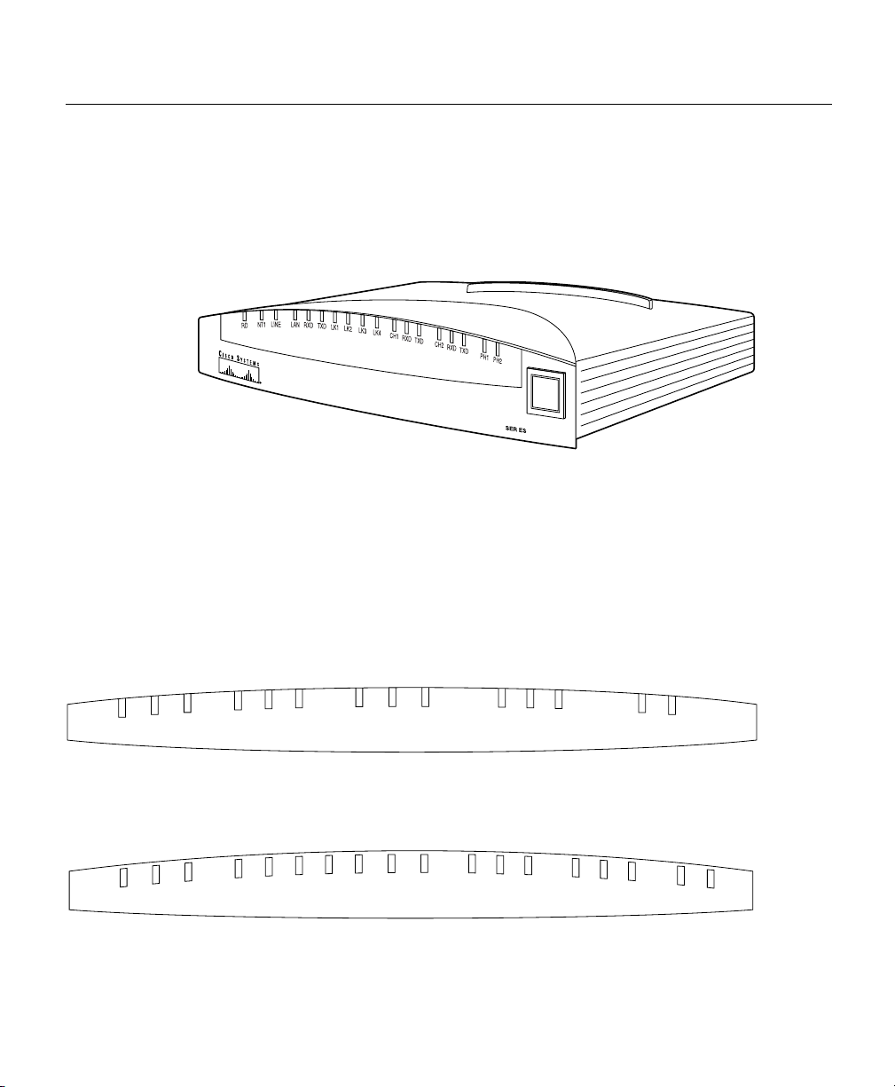
Figure 1-1 shows the front panel of a Cisco 700 series router.
Figure 1-1 Front Panel, Cisco 770 Series Router (Cisco 776 Shown)
Front-Panel LEDs
The LEDs on the front panel of Cisco 700 series routers display the activity status of the
router as connections are made and as packets are sent and received. Figure 1-2 and
Figure 1-3 illustrate the LEDs on the front panels of Cisco 700 series routers.
H7990
Cisco 700
Figure 1-2 Cisco 760 Series LEDs (Cisco 766 Shown)
RD
NT1
LINE
LAN
RXD
TXD
CH1
CH2
TXD
RXD
Figure 1-3 Cisco 770 Series LEDs (Cisco 776 Shown)
LK3
LK4
CH1
RXD
1-10
LK2
LK1
TXD
RXD
LAN
LINE
NT1
RDY
Cisco 700 Series Router Installation Guide
RXD
TXD
TXD
CH2
RXD
TXD
PH1
PH2
PH1
PH2
H5790
H7860
Page 25

Note Cisco 761, Cisco 765, Cisco 771 and Cisco 775 routers do not have NT1 LEDs.
Cisco 761, Cisco 762, Cisco 771 and Cisco 772 routers do not have PH1 and PH2 LEDs.
Table 1-1 lists the LEDs and their functions.
Table 1-1 Front-Panel LED Functions
LED Function
RD (Cisco 760 series)
RDY (Cisco 770
series)
NT1
(Cisco 762,
Cisco 766, Cisco 772,
and Cisco 776 only)
LINE On when the NT1 S interface and the ISDN terminal device(s) are
LAN On when packets have been sent to or received from the Ethernet
RXD Blinks when packets are received from the LAN.
TXD Blinks when packets are sent to the LAN.
LK1 (Cisco 770 only) On when the first LAN link of the unmanaged hub is connected.
LK2 (Cisco 770 only) On when there is a connection on the second LAN link of the
LK3 (Cisco 770 only) On when there is a connection on the third LAN link of the
Indicates the router operating status. On when power is supplied to the
router, the router passes the self-test, and is operating normally.
• On when the internal NT1 and the ISDN switch are synchronized.
• Blinking (5 blinks per second) indicates that the internal NT1 is
attempting to synchronize with the telephone switch.
• Blinking (1 blink per second) indicates that the internal NT1 is
attempting to synchronize with the ISDN terminal devices.
synchronized. Also indicates framing between the router and the
ISDN switch.
within the last minute.
Blinks (once every 1.5 seconds) when there is a problem with the
connection.
unmanaged hub is connected. Blinks (once every 1.5 seconds) when
there is a problem with the connection.
unmanaged hub is connected. Blinks (once every 1.5 seconds) when
there is a problem with the connection.
Overview 1-11
Page 26

Front Panels
Table 1-1 Front-Panel LED Functions (continued)
LED Function
LK4 (Cisco 770 only) On when there is a connection on the fourth LAN link of the
unmanaged hub is connected. Blinks (once every 1.5 seconds) when
there is a problem with the connection.
CH1 Blinks when a call is establishing a connection on the first B channel.
On when a call is established or the connection has not yet timed out.
CH1 RXD Blinks when packets are received on the first B channel.
CH1 TXD Blinks when packets are sent on the first B channel.
CH2 Blinks when a call is establishing a connection on the second
B channel. On when a call is established or the connection has not yet
timed out.
CH2 RXD Blinks when packets are received on the second B channel.
CH2 TXD Blinks when packets are sent on the second B channel.
PH 1
PH 2
(Cisco 765,
Cisco 766, Cisco 775,
and Cisco 776 only)
• Blinks when the corresponding basic telephone service line is
off-hook.
• Blinks in the following patterns when entering DTMF commands
for the corresponding basic telephone service port on the router:
— Blinks twice every second for 2 seconds if the command is
entered correctly.
— Blinks once every second for 4 seconds if the command is
entered incorrectly.
Data Call Button (Cisco 770 Series Routers Only)
The data call button on the front panel of Cisco 770 series routers provides an alternative to
establishing or disconnecting data calls through the command interface. The data call
button performs in Make or Break mode. If no B channels are connected for data, and at
least one B channel is available, the button works in Make mode and attempts to establish
a call. When at least one B channel is connected for data, the button works in Break mode,
disconnecting the call. Table 1-2 summarizes the operation of the Cisco 770 series data call
button.
1-12
Cisco 700 Series Router Installation Guide
Page 27

Table 1-2 Cisco 770 Series Data Call Button Operation Summary
Current Status Data Call Button Operation
No call up Make a data call
1 data call only Disconnect the data call
2 data calls Disconnect both data calls
1 voice call only Make a data call
2 voice calls No action
1 data and 1 voice call Disconnect the data call
Rear Panels
All Cisco 700 series routers include a DB-9F configuration port. Table 1-3 lists the network
interfaces available on each router by model number.
l
Table 1-3 Cisco 700 Series Router Interfaces by Mode
Model Interfaces
Cisco 761 1 Ethernet and 1 ISDN BRI S/T
Cisco 762 1 Ethernet, 1 ISDN BRI S/T, and 1 ISDN BRI U
Cisco 765 1 Ethernet, 1 ISDN BRI S/T, and 2 analog telephone
Cisco 766 1 Ethernet, 1 ISDN BRI S/T, 1 ISDN BRI U, and 2 analog telephone
Cisco 771 4-port unmanaged Ethernet hub and 1 ISDN BRI S/T
Cisco 772 4-port unmanaged Ethernet hub, 1 ISDN BRI S/T, and 1 ISDN BRI U
Cisco 775 4-port unmanaged Ethernet hub, 1 ISDN BRI S/T, and 2 analog telephone
Cisco 776 4-port unmanaged Ethernet hub, 1 ISDN BRI S/T, 1 ISDN BRI U, and
2 analog telephone
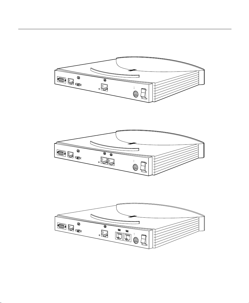
The rear panels of Cisco 760 series routers are shown in Figure 1-4 through Figure 1-7.
Cisco 770 series routers are shown in Figure 1-8 through Figure 1-11.
Overview 1-13
Page 28
Rear Panels
Figure 1-4 Rear Panel, Cisco 761 Router
10B
CONFIG
ASE
T
NODE
HUB
Link
ISDN S/T
S
0
+5V ---1.5A +/-5%
-30V--- 0.2A +/-25%
Figure 1-5 Rear Panel, Cisco 762 Router
10B
CONFIG
A
SET
NODE
HUB
Link
ISDN S/T
ISDN U
S
0
NT-1
+5V ---1.5A +/-5%
-30V--- 0.2A +/-25%
H5906
H5905
1-14
Figure 1-6 Rear Panel, Cisco 765 Router
10B
CONFIG
ASET
NODE
HUB
Link
ISDN S/T
S
0
Cisco 700 Series Router Installation Guide
+5V ---1.5A +/-5%
-30V--- 0.2A +/-25%
H5789
Page 29
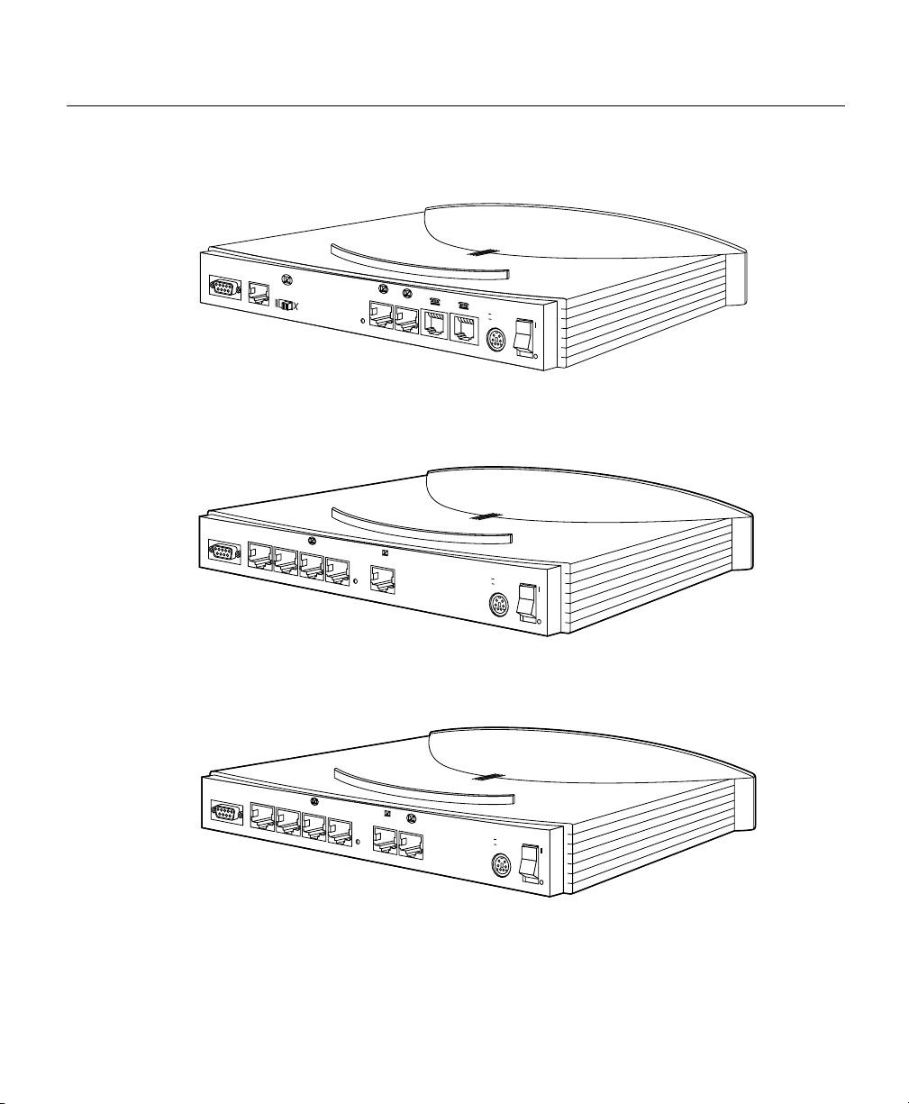
Figure 1-7 Rear Panel, Cisco 766 Router
10B
CONFIG
ASE
T
NODE
HUB
Link
ISDN S/T
ISDN U
S
0
NT-1
+5V ---1.5A +/-5%
-30V--- 0.2A +/-25%
Figure 1-8 Rear Panel, Cisco 771 Router
CONFIG
4
10BASET
3
CISCO 771
2
1
ISDN
S/T
S
0
+5V ---1.5A +/-5%
-30V--- 0.2A +/-25%
Figure 1-9 Rear Panel, Cisco 772 Router
H5788
H8503
CONFIG
4
10BASET
3
CISCO 772
2
1
ISDN S/T
S
0
ISDN U
NT-1
+5V ---1.5A +/-5%
-30V--- 0.2A +/-25%
H8504
Overview 1-15
Page 30
Rear Panels
Figure 1-10 Rear Panel, Cisco 775 Router
CONFIG
4
10BASET
3
CISCO 775
2
1
ISDN
S
/T
S
0
+5V ---1.5A +/-5%
-30V--- 0.2A +/-25%
Figure 1-11 Rear Panel, Cisco 776 Router
CONFIG
4
10BASET
3
CISCO 776
2
1
ISD
N S/T
ISDN U
S
0
NT-1
+5V ---1.5A +/-5%
-30V--- 0.2A +/-25%
H8502
H7861
Rear-Panel LINK LED
There is one LED on the rear panel of Cisco 760 series routers, the LINK LED. The LINK
LED remains lit when a valid physical connection to another Ethernet device is established.
The LINK LED blinks when it is attempting to establish the connection.
1-16
Cisco 700 Series Router Installation Guide
Page 31

Safety
CHAPTER
2
Preparing for Installation
This chapter provides information on the following topics:
• Safety
• Preventing Damage to Your Router
• Unpacking Your Router
• Preparing to Install Your Router
• Where To Go From Here
Observe the caution and warning symbols in this manual. Additional safety information is
provided in the Regulatory, Compliance and Safety Information for Cisco 700 series
routers.
Caution This symbol means reader be careful. In this situation, you might do
something that could result in equipment damage or loss of data.
Warning This warning symbol means danger. You are in a situation that could
cause bodily injury. Before you work on any equipment, be aware of the hazards
involved with electrical circuitry and be familiar with standard practices for
preventing accidents.
Preparing for Installation 2-1
Page 32

Safety
Before installing the router, read these warnings:
Warning Read the installation instructions before you connect the system to its
power source.
Warning Before working on any system, turn the power switch to off and unplug
the power cord.
Warning Before working on equipment that is connected to power lines, remove
jewelry (including rings, necklaces, and watches). Metal objects will heat up when
connected to power and ground and can cause serious burns or weld the metal
object to the terminals.
Warning The ISDN connection is regarded as a source of voltage that should be
inaccessible to user contact. Do not attempt to tamper with or open any public
telephone operator (PTO)-provided equipment or connection hardware. Any hardwired connection (other than by a nonremovable, connect-one-time-only plug)
must be made only by PTO staff or suitably trained engineers.
2-2
Warning To avoid electric shock, do not connect safety extra-low voltage
(SELV) circuits to telephone-network voltage (TNV) circuits. LAN ports contain
SELV circuits, and WAN ports contain TNV circuits. Some LAN and WAN ports
both use RJ-45 connectors. Use caution when connecting cables.
Warning Ultimate disposal of this product should be handled according to all
national laws and regulations.
Cisco 700 Series Router Installation Guide
Page 33

Preventing Damage to Your Router
Use the following guidelines when connecting devices to your router:
• Connect the color-coded cables supplied by Cisco to the color-coded ports on the back
panel.
• If you must supply additional cables, we strongly recommend ordering the cables from
your Cisco 700 series router vendor.
Preventing Electrostatic Discharge Damage
Electrostatic discharge (ESD) is a transfer of electrostatic charge between bodies of
different electrostatic potentials, such as an operator and a piece of electrical equipment. It
occurs when electronic components are improperly handled, and it can damage equipment
and impair electrical circuitry. Electrostatic discharge is more likely to occur with the
combination of synthetic fibers and dry atmosphere.
Always use the following ESD-prevention procedures when removing and replacing
components:
Step 1 Connect the chassis to earth ground with a wire that you provide.
Step 2 Wear an ESD-preventive wrist strap that you provide, ensuring that it makes
good skin contact.
Connect the clip to an unpainted surface of the chassis frame to safely channel
unwanted ESD voltages to ground. To properly guard against ESD damage and
shocks, the wrist strap and cord must operate effectively. If no wrist strap is
available, ground yourself by touching the metal part of the chassis. Always
follow the guidelines in the preceding section, “Safety.”
Step 3 Do not touch any exposed contact pins or connector shells of interface ports that
do not have a cable attached.
If cables are connected at one end only, do not touch the exposed pins at the
unconnected end of the cable.
Note This device is intended for use in residential and commercial environments only.
Preparing for Installation 2-3
Page 34

Unpacking Your Router
Caution Periodically check the resistance value of the antistatic strap, which
should be between 1 and 10 megaohms (Mohms).
Unpacking Your Router
The contents of your Cisco 700 series router package is as follows:
• One Cisco 700 series router.
• One yellow Ethernet cable.
• One red ISDN U cable (Cisco 772 and Cisco 776 routers only).
• One orange ISDN S/T cable (Cisco 771 and Cisco 775 routers only).
• One RJ-45-to-RJ-11 adapter.
• One blue configuration cable.
• One black power supply.
• One black power supply cord.
• One Cisco 700 Series Router Installation Guide.
2-4
• One Documentation CD-ROM set. (The Cisco 700 Series Command Reference is on
Disk 2 of the CD-ROM set.)
• One Cisco 700 Quick Reference Guide.
• One Cisco Fast Step CD-ROM. (The CD-ROM is inside the back cover of the Cisco 700
Quick Reference Guide.)
These items are shown in the Cisco 700 Quick Reference Guide. If any item is missing or
damaged, contact your customer service representative.
Cisco 700 Series Router Installation Guide
Page 35

Preparing to Install Your Router
Before you begin installing your router, perform the following steps:
Step 1 Order an ISDN BRI line from your telephone service provider.
Step 2 If you have a Cisco 761, Cisco 765, Cisco 771, or Cisco 775 router, do the
following:
(a) If you are outside North America, ask your telephone service provider if
you must provide an external Network Termination 1 (NT1) and the ISDN
U cable that connects the NT1 to the ISDN wall jack. Ask for NT1 vendors
if necessary.
(b) If you are inside North America, ask your telephone service provider for
external NT1 vendors. Provide the ISDN U cable that connects the NT1 to
the ISDN wall jack.
Step 3 Be aware of the standard Ethernet and ISDN cable distance limitations.
Step 4 Gather the Ethernet devices to be connected to the router: hub, server,
workstation, or PC.
Step 5 If you have a Cisco 761, Cisco 765, Cisco 771, or Cisco 775 router and plan to
connect a digital telephone, you must provide an NT1 with two S/T interfaces
and one U interface, a telephone cable to connect the telephone (usually this
cable is provided with the device), and an ISDN U cable that connects the NT1
to the ISDN wall jack.
Step 6 If you have a Cisco 765, Cisco 766, Cisco 775, or Cisco 776 router and plan to
connect an analog telephone, fax, or modem, gather these devices. You must also
provide the telephone cable to connect each device (usually this cable is
provided with the device).
Step 7 If you plan to configure the software using a terminal or PC connected to the
router, provide the terminal or PC.
Where To Go From Here
To install the router, continue to Chapter 3, “Installing Your Router.”
Preparing for Installation 2-5
Page 36

Where To Go From Here
2-6
Cisco 700 Series Router Installation Guide
Page 37

CHAPTER
3
Installing Your Router
This chapter describes the tasks necessary to connect your PC or hub through the router to
an ISDN line and connect a PC or ASCII terminal to the router for configuration purposes.
Before you begin, it is important to know if the device you are connecting to a hub or a
node. Basically, a hub is a device that connects three or more nodes. Nodes are everything
else, such as network interface cards (NICs) installed in PCs. For additional information on
hubs and nodes, see the “HUB/NODE Switch” section in Chapter 6, “Concepts and
Descriptions.”
To install your Cisco 700 series router, you must perform the following tasks:
• Connect the Ethernet devices to the router.
• Connect the ISDN line to the router.
• Connect the router to a power source.
• Verify the router installation.
Note The Cisco 700 Quick Reference Guide has diagrams showing common installations.
Connecting Ethernet Devices
The Ethernet ports are marked in yellow on the back panel.
Caution Do not connect the yellow Ethernet ports on your router to any other
port or device, except another Ethernet port. Connecting the cable to the wrong
port can damage your router.
Installing Your Router 3-1
Page 38

Connecting Ethernet Devices
To connect Ethernet devices to the router, complete the following steps:
Step 1 If you are connecting to a node, or if you are connecting a Cisco 761, Cisco 762,
Cisco 765, Cisco 771, Cisco 772, or Cisco 775 router to a hub, connect the
yellow Ethernet cable to the yellow port labeled ETHERNET on the rear panel.
If you are connecting a Cisco 766 or Cisco 776 router to a hub, connect an
Ethernet crossover cable (not supplied) to any open Ethernet port.
Step 2 Connect the other end of the cable to the Ethernet connector on the LAN device,
such as the Ethernet port of the NIC on the back of your computer.
(See Figure 3-1.)
Step 3 Set the HUB/NODE switch if you are connecting a Cisco 700 series router other
than a Cisco 766 or Cisco 776 router.
(a) If your router is connected to another device, such as a NIC in a PC, set the
(b) If your router is connected to an Ethernet hub, set the switch in NODE
switch in HUB position.
position. (Cisco 766 or Cisco 776 routers do not have a HUB/NODE
switch.)
3-2
Cisco 700 Series Router Installation Guide
Page 39

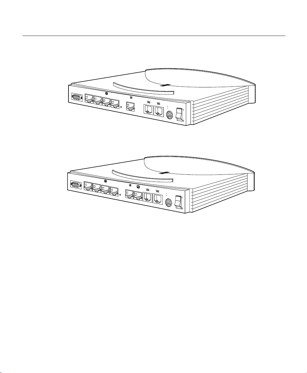
Figure 3-1 Connecting the Ethernet Cable
CONFIG
4
10BASET
3
Connect yellow cable
to yellow Ethernet port
CISCO 776
2
1
ISD
N S/T
ISD
N U
S
0
NT-1
+5V ---1.5A +/-5%
-30V--- 0.2A +/-25%
ETH
OK
LAN
SER 0
17259
AUX
Connect other end of cable
to server, PC, or workstation
Connecting the ISDN Line
The procedure to connect an ISDN line depends on the router and in some cases your
location. The following sections describe each.
Installing Your Router 3-3
Page 40

Connecting the ISDN Line
Provisioning the NT1
Outside of North America, you might need to provide an external network terminator type 1
(NT1) and the ISDN U cable that connects the NT1 to the ISDN wall jack. Contact your
telephone service provider and ask for the following information:
• Is an external NT1 and an ISDN U cable required?
• Does the telephone service provider provide the NT1 or must you supply it?
• If you must supply the NT1, can the telephone service provider provide a list of NT1
vendors?
Inside North America, if you have a 761, 765, 771, or 775, you must provide an external
NT1 and the ISDN U cable that connects the NT1 to the ISDN wall jack. Contact your
telephone service provider for a list of NT1 vendors. If you have a 762, 766, 772, or 776,
you can use the internal NT1 in the router.
Note Detailed information on provisioning your line can be found in Appendix C,
“Provisioning the ISDN BRI Line.” In addition, the Cisco 700 Quick Reference Guide
contains a form to guide you in gathering the provisioning information.
3-4
Warning Network hazardous voltages are present in the ISDN cable. If you
detach the ISDN cable, detach the end away from the router first to avoid possible
electric shock. Network hazardous voltages also are present on the system card in
the area of the ISDN port (RJ-45 connector), regardless of when power is turned
to standby.
Warning Do not work on the system or connect or disconnect cables during
periods of lightening activity.
Warning To reduce the risk of fire, use only No. 26 AWG or larger
telecommunications line cord.
Cisco 700 Series Router Installation Guide
Page 41

Connecting the ISDN Line to the S/T Port
The S/T port connects to some telephone service provider networks using an external NT1.
The need for an external NT1 is determined by your telephone service provider network.
Note If you are interested in the technical aspects of S/T ports, additional information can
be found in the “ISDN Ports” section of Chapter 6, “Concepts and Descriptions.”
Caution Always connect the orange cable to the orange S/T port on the router.
Do not connect the cable to a yellow Ethernet port. This will damage your router.
To connect an ISDN line to the S/T port of a router when your telephone service provider
said that an NT1 is not required, complete the following steps:
Step 1 Connect the orange S/T cable to the orange port labeled S/T on the rear panel of
your router.
Step 2 Connect the other end of the orange S/T cable to the ISDN wall socket. (See
Figure 3-2.)
Installing Your Router 3-5
Page 42

Connecting the ISDN Line
Figure 3-2 Connecting to the ISDN S/T Port When an NT1 Is Not Required
CONFIG
4
10BASET
3
CISCO 776
2
1
Connect orange cable
to orange ISDN S/T port
ISD
N S/T
ISD
N
U
S
0
NT-1
+5V ---1.5A +/-5%
-30V--- 0.2A +/-25%
12760
Connect orange cable
to ISDN wall jack
NT1 Required
3-6
Cisco 700 Series Router Installation Guide
To connect an ISDN line to the S/T port of a Cisco 761, Cisco 762, Cisco 765, Cisco 771,
Cisco 772, or Cisco 775
router when your telephone service provider said that an NT1 is
required, complete the following steps:
Step 1 Connect the orange ISDN S/T cable to the orange port labeled ISDN S/T on the
rear panel of your router.
Step 2 Connect the other end of the orange ISDN S/T cable to the NT1.
Step 3 Connect the ISDN cable provided with the NT1 to the NT1.
Step 4 Connect the other end of the ISDN cable to the ISDN wall jack.
(See Figure 3-3.)
Page 43

Figure 3-3 Connecting to the ISDN S/T Port When an NT1 Is Required
CONFIG
4
10BASET
3
CISCO 776
2
1
ISD
N
S/T
ISD
N
U
S
0
NT-1
Connect orange cable
to orange ISDN S/T port
Connect orange
cable to NT1
+5V ---1.5A +/-5%
-30V--- 0.2A +/-25%
Connect ISDN U
cable to NT1
Connect NT1
power cord to
electrical outlet
Connect cable to
ISDN wall jack
17258
Connecting the ISDN Line to the U Port
The U port connects to the telephone service provider network using the internal NT1.
Figure 3-4 shows the ISDN U port connection.
Caution Always connect the red cable to the red U port on the router. Do not
connect the cable to a yellow Ethernet port. This will damage your router.
Installing Your Router 3-7
Page 44

Connecting the ISDN Line
To connect an ISDN line to the U port on a router, complete the following steps.
Step 1 Connect the red ISDN U cable to the red port labeled ISDN U on the rear panel
Step 2 Connect the other end of the red ISDN U cable to the ISDN wall socket. (See
Figure 3-4 Connecting to the ISDN U Port
CONFIG
of your router.
Figure 3-4.)
4
10BASET
3
2
Connect red cable
to red ISDN U port
CISCO 776
1
ISDN
S/T
ISDN
U
S
0
NT-1
+5V ---1.5A +/-5%
-30V--- 0.2A +/-25%
3-8
Connect red
cable to ISDN
wall jack
Cisco 700 Series Router Installation Guide
17261
RJ-45-to-RJ-11
adapter cable
If your wall jack has an RJ-11 connector,
attach RJ-45-to-RJ-11 adapter cable
to red cable, and then connect RJ-11
connector to ISDN wall jack
Page 45

Connecting the Power Supply
Warning This product relies on the building’s installation for short-circuit
(overcurrent) protection. Ensure that a fuse or circuit breaker no larger than
120 VAC, 15A U.S. (240 VAC, 16A international) is used on the phase conductors
(all current-carrying conductors).
Warning This equipment is intended to be grounded. Ensure that the host is
connected to earth ground during normal use.
To connect the power supply, complete the following steps:
Step 1 Connect the round end of the power supply cable to the black circular power
connector on the rear panel of your router.
Step 2 Connect the black power supply cord to the black power supply.
Step 3 Connect the power supply cord to an electrical outlet. (See Figure 3-5.)
Figure 3-5 Connecting Power Supply (Cisco 765 shown)
10BA
C
O
N
F
IG
Desktop power supply
SET
NODE
HUB
Link
ISDN S/T
S
0
+5V ---1.5A +/-5%
-30V--- 0.2A +/-25%
H5065
DC power input
Installing Your Router 3-9
Page 46

Verifying Installation
Verifying Installation
When the router is powered on, it is automatically booted, and the router attempts to
establish links to the LAN and the WAN.
Compare the LED states with known activity. For example, all LEDs should blink at least
once during the boot process, which takes a few minutes. Once the router is booted, you
can verify your connections by using the LEDs.
The LAN, CH1, and CH2 LEDs each have companion RDX and TDX LEDs. The RDX and
TDX LEDs indicate traffic on the respective channels. Using an application such as a Web
browser, verify that the router is receiving data from the WAN. When you access a Web
page on the network, the router indicates the transfer of data by turning on the LAN LED
and blinking the companion RDX and TDX LEDs. The CH1 LED also turns on and the
companion RDX and TDX LEDs blink. The CH2 LED might turn on, depending on the
amount of traffic. If the LEDs do not behave as expected, check the physical connections.
Brief descriptions of the LED states as they relate to the physical connections are provided
in Table 3-1. All the LEDs are listed, but each router model has a different subset of LEDs.
If your connections are correct and the LEDs are not in the correct state, it might be because
the router or PC is not yet configured. If your router is configured and the states are not
correct, see Chapter 5, “Troubleshooting Cisco 700 Series Routers.”
3-10
Table 3-1 Verifying the Connections
LED Connection Normal Pattern
RDY Power On when the router is powered on.
Off when the router is powered off.
NT1 ISDN U port On when connected.
Blinks when not connected.
LINE ISDN U or S/T port On when connected.
Off when not connected.
LAN Ethernet On for 1 minute after boot.
Off if there is no traffic on the LAN for 1 minute.
Cisco 700 Series Router Installation Guide
Page 47

Table 3-1 Verifying the Connections (continued)
LED Connection Normal Pattern
RDX Ethernet Off when there is no traffic on the network.
On when there is traffic is received from the
network.
TDX Ethernet Off when there is no traffic on the network.
On when there is traffic is transmitted to the
network.
LINK, LK1,
LK2, LK3,
LK4
CH1, CH2 ISDN U or S/T port On when the router has an active voice or data
PH1 and PH2
1 You can also pick up the handset and listen for a dial tone.
Ethernet On when a connection from the Ethernet port to
an Ethernet device is established.
Blinks while attempting to establish a connection.
Off when there is no connection.
connection to the WAN or the channel has not yet
timed out after the connection was closed.
Off when there is no active connection to the
WAN and the channel has timed out.
1
Analog telephone, fax,
or modem
On when telephone, fax, or modem is in use.
Off when not in use.
Where To Go From Here
You have completed the basic hardware installation. You can add digital or analog
telephone devices if desired. For additional information, see Chapter 4, “ISDN and Analog
Telephone Devices.”
If your router has been preconfigured by your vendor or a service provider, you should be
able to turn on your PC, enter the configuration parameters for the PC (your service
provider or network administrator provides these instructions), and connect to the Internet
or your corporate network. Once the connection is established, the installation is complete.
Installing Your Router 3-11
Page 48

Where To Go From Here
If your router is not preconfigured, gather the information listed in Cisco 700 Quick
Reference Guide. This information is commonly available from your ISDN service
provider (telephone company) and the network administrator of the central site network or
your Internet service provider.
Cisco strongly recommends that you use the Cisco 700 Fast Step Setup application unless
you have been instructed to do otherwise. Cisco 700 Fast Step applications are located on
the CD-ROM inside the Cisco 700 Quick Reference Guide.
If you are an experienced user and want to use the command-line interface (CLI) to
configure the software or have been instructed to do so, refer to the Cisco 700 Series
Command Reference for a list of the commands and some configuration examples.
3-12
Cisco 700 Series Router Installation Guide
Page 49

ISDN and Analog Telephone Devices
This chapter describes how to connect an ISDN or analog telephone to a Cisco 700 series
router and how to configure the router to support that telephone. An ISDN telephone can
be connected to the ISDN S/T port of any Cisco 700 series router. An analog telephone can
be connected to a Cisco 765, Cisco 766, Cisco 775, or Cisco 776 router basic telephone
service port (also known as “plain old telephone service” or “POTS” port).
Note During a voice call, if the remote party hangs up the receiver and your receiver
remains off-hook, you will hear a fast busy tone after 30 seconds.
Connecting an ISDN (Digital) Telephone
You can connect an ISDN telephone to any Cisco 700 series router with an S/T port. The
ISDN telephone communicates over the same ISDN line the router uses to send and receive
data. ISDN telephones are available in two basic models, self-powered (described in the
section “Connecting a Self-Powered Digital Telephone”) and with an independent power
supply (described in the section “Connecting a Digital Telephone with an External Power
Supply”).
CHAPTER
4
Warning This equipment contains a ring signal generator (ringer), which is a
source of hazardous voltage. Do not touch the RJ-11 (phone) port wires
(conductors), the conductors of a cable connected to the RJ-11 port, or the
associated circuit-board when the ringer is active. The ringer is activated
(indicated by a clicking sound) by an incoming call.
ISDN and Analog Telephone Devices 4-1
Page 50

Connecting an ISDN (Digital) Telephone
Caution Do not connect the router telephone ports to the telephone wall jack.
These ports are not meant for direct connection to a public network. This
connection can damage your router.
Connecting a Self-Powered Digital Telephone
You can connect an ISDN telephone to the Cisco 761, Cisco 765, Cisco 771, or Cisco 775
only through an external NT1 connector. If you are connecting an ISDN telephone directly
to the Cisco 762, Cisco 766, Cisco 772, or
(provided with the ISDN telephone) to the RJ-45 port labeled ISDN S/T on the rear panel
of the router. Cable the ISDN wall jack to the port labeled ISDN U. (See Figure 4-1.)
Refer to the instructions provided by the manufacturer of the telephone.
Cisco 776, connect the ISDN telephone cable
4-2
Cisco 700 Series Router Installation Guide
Page 51

Figure 4-1 ISDN Telephone to Router Connection (Cisco 766 Shown)
10BASET
C
O
N
F
IG
N
OD
E
HU
B
RJ-45-to-RJ-45 cable
Link
ISDN S/T
ISDN U
S
0
NT-1
+5V ---1.5A +/-5%
-30V--- 0.2A +/-25%
H10772
RJ-45-to-RJ-45 cable
ISDN wall jack
ISDN telephone
Connecting a Digital Telephone with an External Power Supply
This section describes how to connect an ISDN telephone that requires an external power
supply to the router. Depending upon the ISDN telephone model and power supply model
you use, the procedure to connect the ISDN telephone and power supply might differ
slightly. This example procedure describes how to connect an AT&T ISDN telephone
(model ISDN 8510T) and an AT&T external power supply (model MSP-1). Also refer to
the instructions provided by the manufacturer of the telephone.
ISDN and Analog Telephone Devices 4-3
Page 52

Connecting an ISDN (Digital) Telephone
You must provide the following equipment:
• NT1 with two S/T interfaces and one U interface.
• Telephone cable to connect digital telephone. (This cable is usually provided with the
telephone.)
• ISDN U cable that connects the NT1 to the ISDN wall jack.
Take the following steps to connect the ISDN telephone and external power supply. This
procedure assumes you have connected the ISDN U port to the ISDN wall jack (see
Figure 4-1).
Step 1 Connect an RJ-45-to-RJ-45 cable (included) from the ISDN S/T port (on the rear
panel of the router) to the port labeled LINE on the ISDN telephone power
supply. (See Figure 4-2.)
Step 2 Connect the ISDN telephone RJ-45 cable to the port labeled PHONE on the
ISDN telephone power supply. (See Figure 4-2.)
Step 3 Connect the telephone power supply to the power outlet.
You can now use the ISDN telephone on the same ISDN line as the router.
4-4
Cisco 700 Series Router Installation Guide
Page 53

Figure 4-2 Router to ISDN Power Supply Connection (Cisco 766 Shown)
10B
CONFIG
ASE
T
NODE
HUB
Power supply for
ISDN telephone
PHONE
Link
ISDN S/T
ISDN U
S
0
NT-1
From ISDN S/T port
LINE
OTHER
+5V ---1.5A +/-5%
-30V--- 0.2A +/-25%
RJ-45-to-RJ-45 cable
H10774
Connecting an Analog Telephone Device
If you are using a Cisco 765, Cisco 766, Cisco 775, or Cisco 776, you can connect one or
two analog devices, such as a telephone, fax machine, or modem, directly to the router. The
analog device is connected to basic telephone services through the same ISDN line the
router uses.
Also, if you are outside of North America, you might need to provide an adapter cable for
the type of connector that your device uses (the telephone uses an RJ-11 connector.)
To connect the analog device to the router, connect the telephone cable (provided with the
analog device) to the RJ-11 port (labeled with a telephone icon) on the rear panel of the
router, as shown in Figure 4-3.
ISDN and Analog Telephone Devices 4-5
Page 54

Supplementary Services
Figure 4-3 Analog Telephone to Router Connection (Cisco 766 Shown)
CONFIG
10BA
S
ET
NODE
HUB
RJ-11 telephone cable
Link
ISDN S/T
ISDN
U
S
0
NT-1
+5V
---1.5A +/-5%
-30V
--- 0.2A +/-25%
H10773
Analog
telephone
Supplementary Services
This section describes how to configure the Cisco 765, Cisco 766, Cisco 775, and
Cisco 776 routers for supported supplementary services. These are the only models that
support the following supplementary services:
• Call Waiting
• Call Hold and Retrieve
• Call Transfer
• Three-Way Call Conferencing
Cisco 700 series routers do not support Open Service Intervals or Battery Reversal.
4-6
Cisco 700 Series Router Installation Guide
Page 55

Call Waiting
Note To use DTMF commands from the telephone keypad, the set local access command
must be set to on.
Note In this section, the term on-hook means to hang up the telephone.
Call waiting sounds a tone if you are already on a call and there is a second incoming call.
Your BRI line must be provisioned for the additional call offerings (ACOs) call hold and
call retrieve to use call waiting. (For more information on ACOs, refer to the appendix
“Provisioning the ISDN BRI Line.”) One analog telephone interface can support two calls;
therefore, only one call at a time can be waiting.
To retrieve the new call, perform a flash or short on-hook (quickly press the telephone
receiver button once) to place the call in progress on hold and answer the new call. If your
analog telephone offers the option, you can press the Flash key instead of the telephone
receiver button to put the call on hold and answer the new call.
You can toggle between calls on the same analog telephone interface by performing the
short on-hook or by using the Flash key.
If you terminate one call and return the receiver to the hook, the waiting call remains active.
The telephone rings, and when you pick up the receiver, you are connected to the waiting
call.
The set callwaiting command enables call waiting for the analog port specified. Following
is an example of the set callwaiting command that turns on the call waiting feature on the
phone1 port:
766> set callwaiting interface phone1 on
ISDN and Analog Telephone Devices 4-7
Page 56

Supplementary Services
Disabling Call Waiting
Depending upon the devices connected to the analog telephone ports, it might be necessary
to disable call waiting, for example, if the tone generated by the call waiting service
interrupts data transfer when using an analog fax machine connected to the router. (Consult
the instructions provided by the manufacturer of the device to determine if this is
necessary.)
The set callwaiting command disables call waiting for the analog port specified. Following
is an example of the set callwaiting command that turns off the call waiting feature on the
phone1 port:
766> set callwaiting interface phone1 off
Disabling Call Waiting on a Per-Call Basis
When making an outgoing voice call over one of the analog telephone ports, you might
want to disable the call waiting feature on a per-call basis. To disable call waiting, use the
dual tone multifrequency (DTMF) command, dialed on the keypad of the telephone, as
shown in the following example:
**99#
When the voice call is completed, call waiting is restored.
Call Hold and Retrieve
Call hold and retrieve is the ability to place a caller on hold, make a second call, and return
to the first call. (Some countries that use the NET3 switch do not support ISDN
provisioning for call hold and call retrieve.)
To place a call on hold:
Step 1 Perform a short on-hook (quickly press the telephone receiver button once) to
get a dial tone.
If your analog telephone device offers the option, you can press the Flash key
instead of the short on-hook to put the call on hold.
Step 2 Dial the hold access number, **95#.
Step 3 Dial the second call.
4-8
Cisco 700 Series Router Installation Guide
Page 57

To retrieve the call placed on hold, perform the short on-hook or press the Flash key again.
If you have a call on hold and you hang up, the telephone rings, indicating a call is on hold.
Picking up the telephone receiver connects you to the caller on hold.
Call Transfer
Call transfer is the ability to transfer an active call to another number. (Some countries that
use the NET3 switch do not support ISDN provisioning for call transfer.)
Take the following steps to transfer an active incoming call to another telephone number:
Step 1 Perform a short on-hook (quickly press the telephone receiver button once) to
Step 2 Dial the number to which the call is to be transferred.
Step 3 Hang up the receiver. The call is transferred.
get a dial tone.
If your analog telephone device offers the option, you can press the Flash key
instead of the short on-hook to put the call on hold.
You can also return to the original call by performing another short on-hook.
If the transfer fails, the caller remains on hold, and the telephone rings to alert
you to the call on hold.
Three-Way Call Conferencing
Three-way call conferencing adds another party to an active call. (Some countries that use
the NET3 switch do not support ISDN provisioning for three-way call conferencing.) Up
to three people can be connected using three-way conferencing. (It is a known limitation
that no more than two Cisco 700 series routers can be connected.)
Take the following steps to add a third party to an active call:
Step 1 Perform a short on-hook (quickly press the telephone receiver button once) to
get a dial tone.
If your analog telephone device offers the option, you can press the Flash key
instead of the short on-hook to put the call on hold.
ISDN and Analog Telephone Devices 4-9
Page 58

Country-Specific Dialing Instructions
Step 2 Dial the second call.
Step 3 When the second call is answered, perform a short on-hook to connect the
original caller.
Country-Specific Dialing Instructions
Integrated Network Service (INS) ISDN lines are used in Japan. NET3 lines are used
throughout Europe and parts of Asia. 1TR6 ISDN lines are used throughout Europe. This
section describes analog telephone dialing instructions specific to these countries.
Dialing with INS ISDN Lines for Japan
To make an analog telephone call over INS ISDN lines in Japan from a telephone connected
to Cisco 700 series routers, take the following steps:
Step 1 Enter each individual number (called a dialing digit) of the telephone number on
the telephone keypad.
You must enter each successive dialing digit within 6 seconds of entering the
previous digit. If you wait longer than 6 seconds, an incomplete set of dialing
digits is sent to the switch.
4-10
Step 2 Send the entire set of dialing digits to the switch in one of the following ways:
• Press the pound (#) key on the telephone keypad.
• Wait 6 seconds without entering any more dialing digits on the telephone
keypad. After 6 seconds, the set of dialing digits is automatically sent to the
switch.
Cisco 700 Series Router Installation Guide
Page 59

Disabling the Pound Key’s End-of-Dial Function
If the pound (#) key is one of the dialing digits in a telephone number, you can disable the
end-of-call function on a per-call basis. This command applies only to INS router software.
To disable the end-of-call function, use the following DTMF command:
**98#
After entering the **98# command, wait for the dial tone and enter the desired dialing
digits, including the pound (#) key. The call is sent 6 seconds after the last dialing digit is
entered. When the call is terminated, the end-of-call function is restored for the next call.
Internal Tones for NET3 and 1TR6 ISDN Lines for Europe
Depending on the ISDN service provider, certain internal tones, such as dial, ring back, and
busy tones, might not be provided by the telephone switch (the device on the other end of
the ISDN line). If this is the case with the ISDN line you are using, you can configure
Cisco 700 series routers to provide just the dial tone or all tones. This command applies
only to NET3 router software and to 1TR6 router software.
The set internaltones command provides just the dial tone or all internal tones. By default,
the router provides all internal tones.
The following is an example of a set internaltones command that enables the dial tone
only:
766> set internaltones dialtone
Call Forwarding in Sweden and Finland
Call Forwarding supplementary service has been added to software Release 4.0(2) and
higher for Sweden and Finland (NET3). The Call Forwarding types supported are as
follows:
Call Forwarding Unconditional (CFU)—Enables the network to redirect all incoming calls
to another party, regardless of the status of the user.
Call Forwarding No Reply (CFNR)—Enables the network to redirect calls to another party
when the call is not established within a predefined period of time.
ISDN and Analog Telephone Devices 4-11
Page 60

Country-Specific Dialing Instructions
Call Forwarding Busy (CFB)—Enables the network to redirect to another party calls that
meet a busy condition.
In all types of Call Forwarding, the user’s ability to originate calls is unaffected by the Call
Forwarding supplementary service.
The feature numbers for Call Forwarding are provided here for convenience, but they could
be different in your area, depending upon the local telephone service provider.
To activate Call Forwarding:
Step 1 Take the phone off hook.
Step 2 Dial *feature number* phone number to be forwarded to #.
Step 3 Hang up. You might hear a confirmation signal from the network before you
hang up.
To deactivate Call Forwarding:
Step 1 Take the phone off hook.
Step 2 Dial #feature number#.
If the wrong feature number is entered, you might hear a signal indicating the
wrong feature number was entered or the activation or deactivation failed.
Call Forwarding Unconditional
Activation: *21*forwarded-to number#
Deactivation: #21#
Call Forwarding No Reply
Activation: *61*forwarded-to number#
Deactivation: #61#
4-12
Cisco 700 Series Router Installation Guide
Page 61

Call Forwarding Busy
Activation: *67*forwarded-to number#
Deactivation: #67#
The switch type NET3 supports these features where the country group must be set for
Sweden and Finland.
There is no equivalent command-line command to activate or deactivate Call Forwarding.
The phone number to which calls are redirected is not displayed.
All types of Call Forwarding supplementary services must be provisioned on the ISDN line
for the service to be available.
Where To Go From Here
If your router has been preconfigured, there is nothing more to do except power on the
router.
If you are using the Cisco 700 Fast Step Setup application to configure your router, it
includes steps to configure the digital and analog devices attached to your router. Cisco 700
Fast Step applications are on the CD-ROM inside the Cisco 700 Quick Reference Guide.
If you are an experienced user and want to use the command-line interface (CLI) to
configure the digital and analog devices or have been instructed to do so, refer to the
Cisco 700 Series Command Reference for a list of the commands and some configuration
examples. The Cisco 700 Series Command Reference is on the Documentation CD.
ISDN and Analog Telephone Devices 4-13
Page 62

Where To Go From Here
4-14
Cisco 700 Series Router Installation Guide
Page 63

Troubleshooting Cisco 700
Series Routers
This chapter helps you find solutions to problems you might be having with your router.
Begin by attempting to isolate the problem to a specific source.
Power-On Self-Test
When the router is powered on, it performs a series of self-tests. After these tests are
completed, the LEDs indicate operating status. Any operational problem is represented by
a combination of lit and unlit LEDs. Cisco 760 series routers have 12 to 14 (depending on
the model) LEDs on the front panel. Cisco 770 series routers have 15 to 18 LEDs on the
front panel.
CHAPTER
5
Note The function of each LED is described in the “Front-Panel LEDs” section of
Chapter 1, “Overview.”
LED Diagnostics
The front-panel LEDs can be used for diagnostic purposes. Table 5-1 lists the combinations
of lit and unlit LEDs and their significance.
To verify your Ethernet connection, check that one of the following LEDs is on:
Table 5-1 LED Error Messages
RDY NT1 LINE CH1 CH2 Test Result
On Blinks several
times a
second
Off Off Off Internal NT1 is unable to synchronize with the
ISDN switch.
Troubleshooting Cisco 700 Series Routers 5-1
Page 64

Power-On Self-Test
Table 5-1 LED Error Messages (continued)
RDY NT1 LINE CH1 CH2 Test Result
On Blinks once a
Off Off On Off Off Waiting for software.
OnOff OnOnOnProcessor inactive.
Off Off Off Off Off Processor self-test error.
Off Off Off Off On EPROM
Off Off Off On Off RAM error.
Off Off Off On On Flash memory error.
Off Off On Off On HDLC
Off Off On On Off Configuration port error.
Off Off On On On ISDN interface chip error.
1 EPROM = erasable programmable read-only memory.
2 HDLC = High-Level Data Link Control.
second
Off Off Off Internal NT1 is synchronized with the ISDN
switch, but is unable to synchronize with the
ISDN terminal devices.
1
checksum error.
2
packet chip error.
TWAIT Timer
During initialization (power-up or reboot), with the switch type set to NI1, the following
message displays:
The timer value varies from 1 second to 5 minutes. Upon expiration of the time, the router
requests a terminal endpoint identifier (TEI) and initiates SPID initialization as usual. If
needed, either a voice or data call can be initiated instead of waiting for the timer to expire.
This stops the timer immediately and allows initialization to continue.
Note that the call will be successful unless the ISDN line has not been given enough time
to rest before power-up or reboot.
5-2
Cisco 700 Series Router Installation Guide
host> Please wait for TWAIT timer to expire in __ seconds
host> Make a call to bypass this timer
Page 65

Communicating with the WAN
This section describes the problems and solutions commonly found in Cisco 700 series
router configurations.
Terminal Identifier or SPID Problems
Either of the following messages received on your terminal might indicate a SPID
configuration problem:
Channel Not Available
Facility Not Subscribed
Check for the following conditions:
• The wrong ISDN switch type was set. Change the switch type by using the set switch
command or the Cisco 700 Fast Step Setup application.
• The ISDN line was incorrectly configured by the ISDN service provider. Confirm the
line configuration with the ISDN service provider.
• The SPIDs were not entered or were entered incorrectly. Enter or change the SPIDs by
using the set spid command or the Cisco 700 Fast Step Setup application.
Outgoing Calls Cannot be Initiated
If outgoing calls are unsuccessful, check for the following conditions:
• A telephone number was not correctly configured. Enter or change the number with the
set number command or the Cisco 700 Fast Step Setup application.
• The ISDN B channel is under operator control and does not respond to the router.
Contact your ISDN service provider.
• The SPIDs were not entered or were entered incorrectly. Enter or change the SPIDs by
using the set spid command or the Cisco 700 Fast Step Setup application.
Troubleshooting Cisco 700 Series Routers 5-3
Page 66

Communicating with the WAN
Outgoing Calls are Rejected
If an outgoing call is initially successful and then rejected, check for the following
conditions:
• A telephone number was incorrectly configured with the set number command.
• To resolve error messages such as “Incompatible Destination,” use the set number
command to enter a 1 at the beginning of the number, even if the number called is in the
same area code. (Some networks require the 1 to connect a data call at 64 kbps.)
• The number called is busy. Try the call again.
• The ISDN line was incorrectly configured by the ISDN service provider. Confirm the
line configuration with the ISDN service provider.
• If using authentication, the client password or secret might not match the remote router’s
host password or secret.
Incoming Calls Not Received
If the router places outbound calls without any problems, but cannot receive incoming calls,
check the following:
• Verify the directory numbers are set correctly. Enter or change the number with the set
directory number command or the Cisco 700 Fast Step Setup application.
• ISDN line provisioning is correct. Confirm the line configuration with the ISDN service
provider.
• PPP host secret and password match the client secret and password. Confirm the
passwords with the ISDN service provider.
• A profile with a name matching the client host name exists. Rename or delete the
profile.
Router Calls Itself
ISDN supports two separate logical data channels on the same physical line. If these two
numbers are the same, the router might attempt to call itself when on-demand dialing is
enabled or if the user issues the call command.
5-4
Cisco 700 Series Router Installation Guide
Page 67

If the router calls itself, check that the number configured with the set number command
is not the same as the number configured with the set directory number command.
Communicating with the LAN
If you have problems communicating with a 10BaseT Ethernet LAN device (such as your
PC), do the following:
• Verify the LINK LED on the back panel of all models except Cisco 766 or Cisco 776
routers or at least one of the link (LK1, LK2, LK3, or LK4) LEDs on Cisco 766 or
Cisco 776 routers is on, indicating the router is communicating with the LAN device. If
the LED is blinking, it is attempting to establish a connection. Check the Ethernet cables
or the device attached to the other end of the cable, such as the network interface card
(NIC) in your PC.
• Verify the LAN LED on the front panel is lit, indicating the router is communicating
with the LAN device. If the LED is blinking, it is attempting to establish a connection.
Check the Ethernet cables or the device attached to the other end of the cable, such as
the NIC in your PC.
• Check the HUB/NODE switch located on the back panel of all models except Cisco 766
or Cisco 776 routers. This switch eliminates the need for an Ethernet crossover cable
when connecting to a hub. If it is in the wrong position, it will not cause any damage to
the equipment; however, the signals will not be sent to the correct location. If you are
connecting directly to a PC, the switch should be in the HUB position. If you are
connecting to a hub, the switch should be in the NODE position.
Note For a description of the HUB/NODE switch function, see “HUB/NODE Switch”
section in Chapter 6, “Concepts and Descriptions.”
Troubleshooting Cisco 700 Series Routers 5-5
Page 68

Inband Timeout Violation
Inband Timeout Violation
The Inband Timeout Violation error message indicates the router cannot communicate with
the remote device after an ISDN connection had been established. This might be caused by
the speed of the connection. Under some conditions, the router attempts to connect at
56 kbps, and the remote device attempts to connect at 64 kbps. The data becomes unusable.
Set the speed to 64 kbps, and attempt the connection again.
ISDN BRI Cause Values
This section describes ISDN BRI standard cause values that might be received from the
ISDN switch when using Cisco 700 series routers. These values are sent from the ISDN
switch to the router to indicate ISDN call status.
Although ISDN service providers generally define cause messages with decimal values,
Cisco 700 series routers display the hexadecimal (or hex) translation of the decimal value.
Table 5-2 lists the ISDN BRI cause values, the hexadecimal translation, the cause message,
and a short definition of the cause message. Cause values are standardized; however, each
ISDN service provider uses its own version of the cause message wording. Therefore, the
cause messages shown in Table 5-2 might not match the messages exactly as they appear
on the terminal.
5-6
Table 5-2 ISDN BRI Cause Values and Cause Messages
Cause
Val ue
1 0001 Unassigned
2 0002 No route to
3 0003 No route to
Cisco 700 Series Router Installation Guide
Hex
1
Val ue
2
Cause Message Definition
number
specified transit
network
destination
The ISDN number was sent to the switch in the
correct format; however, the number is not
assigned to any destination equipment.
The ISDN exchange is asked to route the call
through an unrecognized intermediate network.
The call was routed through an intermediate
network that does not serve the destination
address.
Page 69

Table 5-2 ISDN BRI Cause Values and Cause Messages (continued)
Cause
Val ue
6 0006 Channel
7 0007 Call awarded and
16 0010 Normal call
Hex
1
Val ue
2
Cause Message Definition
The service quality of the specified channel is
unacceptable
insufficient to accept the connection.
The user is assigned an incoming call that is
delivered
connected to a channel with an established call.
Normal call clearing has occurred.
clearing
17 0011 User busy The called system acknowledges the connection
request, but is unable to accept the call because all
B channels are in use.
18 0012 No user responding The connection cannot be completed because the
destination does not respond to the call.
19 0013 No answer from
user (user alerted)
The destination responds to the connection
request, but fails to complete the connection
within the prescribed time. The problem is at the
remote end of the connection.
21 0015 Call rejected The destination is capable of accepting the call,
but rejected the call for an unknown reason.
22 0016 Number changed The ISDN number used to set up the call is not
assigned to any system. (If an alternate address is
assigned to the called equipment, it might be
returned in the diagnostic field of this message.)
26 001A Non-selected user
clearing
The destination is capable of accepting the call,
but rejected the call because it was not assigned to
the user.
27 001B Destination out of
order
The destination cannot be reached because the
interface is not functioning correctly, and a
signaling message cannot be delivered. This
might be a temporary condition, but could last for
an extended period of time. For example, the
remote equipment might be turned off.
Troubleshooting Cisco 700 Series Routers 5-7
Page 70

ISDN BRI Cause Values
Table 5-2 ISDN BRI Cause Values and Cause Messages (continued)
Cause
Val ue
28 001C Invalid number
Hex
1
Val ue
2
Cause Message Definition
The connection could be established because the
format
destination address was presented in an
unrecognizable format or because the destination
address was incomplete.
29 001D Facility rejected The facility requested by the user cannot be
provided by the network.
30 001E Response to
STATUS
ENQUIRY
31 001F Normal,
unspecified
34 0022 No circuit/channel
available
38 0026 Network out of
order
The status message was generated in direct
response to the receipt of a status inquiry
message.
Reports the occurrence of a normal event when no
standard cause applies. No action required.
The connection cannot be established because no
appropriate channel is available to take the call.
The destination cannot be reached because the
network is not functioning correctly, and the
condition might last for an extended period of
time. An immediate reconnect attempt will
probably be unsuccessful.
41 0029 Temporary failure An error occurred because the network is not
functioning correctly. The problem will be
resolved shortly.
42 002A Switching
equipment
congestion
43 002B Access information
discarded
44 002C Requested
circuit/channel not
available
47 002F Resource
unavailable,
unspecified
The destination cannot be reached because the
network switching equipment is temporarily
overloaded.
The network cannot provide the requested access
information.
The remote equipment cannot provide the
requested channel for an unknown reason. This
might be a temporary problem.
The requested channel or service is unavailable
for an unknown reason. This might be a
temporary problem.
5-8
Cisco 700 Series Router Installation Guide
Page 71

Table 5-2 ISDN BRI Cause Values and Cause Messages (continued)
Cause
Val ue
Hex
1
Val ue
2
Cause Message Definition
49 0031 Quality of service
unavailable
50 0032 Requested facility
not subscribed
57 0039 Bearer capability
not authorized
58 003A Bearer capability
not presently
available
63 003F Service or option
not available,
unspecified
65 0041 Bearer capability
not implemented
66 0042 Channel type not
implemented
69 0045 Requested facility
not implemented
70 0046 Only restricted
digital information
bearer is available
79 004F Service or option
not available,
unspecified
The requested quality of service (as defined by
3
recommendation X.213) cannot be
CCITT
provided by the network. This might be a
subscription problem.
The remote equipment supports the requested
supplementary service, but only by subscription.
The user requested a bearer capability (BC) that
the network provides, but that the user is not
authorized to use. This might be a subscription
problem.
The network normally provides the requested BC,
but not at the present time. This might be due to a
temporary network problem or to a subscription
problem.
The network or remote equipment was unable to
provide the requested service option for an
unspecified reason. This might be a subscription
problem.
The network cannot provide the bearer capability
(BC) requested by the user.
The network or the destination equipment does
not support the requested channel type.
The remote equipment does not support the
requested supplementary service.
The network is unable to provide unrestricted
digital information BC.
The network or remote equipment is unable to
provide the requested service option for an
unspecified reason. This might be a subscription
problem.
Troubleshooting Cisco 700 Series Routers 5-9
Page 72

ISDN BRI Cause Values
Table 5-2 ISDN BRI Cause Values and Cause Messages (continued)
Cause
Val ue
81 0051 Invalid call
Hex
1
Val ue
2
Cause Message Definition
The remote equipment received a call with a call
reference value
reference that is not currently in use on the
user-network interface.
82 0052 Identified channel
does not exist
The receiving equipment is requested to use a
channel that is not activated on the interface for
calls.
83 0053 A suspended call
exists but this call
identity does not
The network received a call resume request. The
call resume request contained a Call Identify
information element that indicates that the call
identity is being used for a suspended call.
84 0054 Call identity in use The network received a call resume request. The
call resume request contained a Call Identify
information element that indicates that it is in use
for a suspended call.
85 0055 No call suspended The network received a call resume request when
there was not a suspended call pending. This
might be a transient error that will be resolved by
successive call retries.
86 0056 Call having
requested call
identity has been
cleared
The network received a call resume request. The
call resume request contained a Call Identity
information element, which once indicated a
suspended call. However, the suspended call was
cleared either by timeout or by the remote user.
88 0058 Incompatible
destination
Indicates that an attempt was made to connect to
non-ISDN equipment, for example, to an analog
line.
91 005B Invalid transit
network specified
95 005F Invalid message,
unspecified
The ISDN exchange was asked to route the call
through an unrecognized intermediate network.
An invalid message was received, and no standard
cause applies. This is usually due to a D-channel
error. If this error occurs systematically, report it
to your ISDN service provider.
5-10
Cisco 700 Series Router Installation Guide
Page 73

Table 5-2 ISDN BRI Cause Values and Cause Messages (continued)
Cause
Val ue
Hex
1
Val ue
2
Cause Message Definition
96 0060 Mandatory
information
element is missing
97 0061 Message type
non-existent or not
implemented
98 0062 Message
incompatible with
call state or
message type
non-existent
99 0063 Information
element
nonexistent or not
implemented
100 0064 Invalid information
element contents
101 0065 Message not
compatible with
call state
102 0066 Recovery on timer
expiry
111 006F Protocol error,
unspecified
The receiving equipment received a message that
did not include one of the mandatory information
elements. This is usually due to a D-channel error.
If this error occurs systematically, report it to your
ISDN service provider.
The receiving equipment received an
unrecognized message, either because the
message type was invalid or because the message
type was valid but not supported. Cause 97 is due
to either a problem with the remote configuration
or a problem with the local D channel.
The remote equipment received an invalid
message, and no standard cause applies. Cause 98
is due to a D-channel error. If this error occurs
systematically, report it to your ISDN service
provider.
The remote equipment received a message that
includes information elements, which were not
recognized. This is usually due to a D-channel
error. If this error occurs systematically, report it
to your ISDN service provider.
The remote equipment received a message that
includes invalid information in the information
element. This is usually due to a D-channel error.
The remote equipment received an unexpected
message that does not correspond to the current
state of the connection. This is usually due to a
D-channel error.
An error-handling (recovery) procedure was
initiated by a timer expiration. This is usually a
temporary problem.
An unspecified D-channel error when no other
standard cause applies.
Troubleshooting Cisco 700 Series Routers 5-11
Page 74

ISDN BRI Cause Values
Table 5-2 ISDN BRI Cause Values and Cause Messages (continued)
Cause
Val ue
127 007F Interworking,
Hex
1
Val ue
2
Cause Message Definition
An event occurred, but the network does not
unspecified
provide causes for the action that it takes. The
precise problem is unknown.
UNKNOWN– Unknown or local
error
An event occurred, but the network does not
provide causes for the action that it takes. The
precise problem is unknown.
1 Cause value is shown in decimal format.
2 Hex value = hexadecimal translation of the decimal cause value.
3 CCITT = Consultative Committee for International Telegraph and Telephone.
5-12
Cisco 700 Series Router Installation Guide
Page 75

Concepts and Descriptions
This chapter provides technical explanations of many of the features of the Cisco 700 series
router. Although this information is not required to successfully install the router, it might
be of interest and assist with troubleshooting efforts.
Definition of Terms and Acronyms
This section defines some networking terms you will encounter when gathering required
information and using Cisco 700 series router manuals to configure the router.
Access code
A number that must be dialed preceding the telephone number to dial outside of a
specific telephone system, such as a Centrex system.
CHAPTER
6
AT commands
ATtention commands (used for modem communications)
BT
British Telecom
Challenge Handshake Authentication Protocol (CHAP)
A form of PPP authentication that requires an exchange of user names and secrets
(encrypted passwords) between two devices. This security feature is supported on lines
using PPP encapsulation. CHAP passwords are called secrets because they are sent
encrypted. Both devices must support PPP.
Concepts and Descriptions 6-1
Page 76

Definition of Terms and Acronyms
Directory numbers
The equivalent of telephone numbers. This is the number the router dials to connect to
a remote router. ISDN BRI lines are generally assigned two local directory numbers,
one for each B channel.
EPOS
Electronic Point of Sale
IE
Information Element of a Q.931 message
Integrated Services Digital Network (ISDN) Basic Rate Interface (BRI)
A digital communication medium that operates over existing analog telephone lines.
The BRI provides two 64-kbps B channels (for voice and data) and one 16-kbps D
channel (for customer and call information). This channel combination is sometimes
denoted as 2B+D.
Internet Protocol (IP) address
A network address that uniquely identifies a device on an IP network. This type of
address consists of 4 bytes, represented as decimal values, separated by periods, as in
123.45.67.89.
6-2
Media Access Control (MAC) address
Also known as a hardware address. This address is assigned by the device manufacturer,
for example, 1234.5678.9000.
Point-to-Point Protocol (PPP)
A direct connection between two nodes; a connection without any intervening nodes or
switches. In an internetwork, the term refers to a direct connection between two
networks.
Password Authentication Protocol (PAP)
A form of PPP authentication that requires an exchange of user names and clear-text
passwords between two devices. PAP passwords are sent unencrypted. Both devices
must support PPP.
PAT
Port Address Translation
Cisco 700 Series Router Installation Guide
Page 77

PSTN
RIP
Service Profile Identifiers (SPIDs)
TCP
TPAD
ISDN Ports
Cisco 700 series routers provide one basic rate interface (BRI). The ISDN BRI service
provided by your telephone service provider offers two bearer channels (B channels) and
one data channel (D channel). The B channel operates at 64 kbps and carries user data. The
D channel operates at 16 kbps and carries control and signaling information, although it can
support user data transmission under certain circumstances.
Public Switched Telephone Network
Routing Information Protocol
Numbers assigned by the ISDN service provider that identify the ISDN B channels.
They are assigned only in North America. The SPID format is generally the ISDN
telephone number with several numbers added to it. Depending on the switch type
supporting your ISDN BRI line, your ISDN line might be assigned none, one, or two
SPIDs.
Transmission Control Protocol
Terminal Packet Assembler and Disassembler
Outside North America, telephone service providers typically provide an S/T interface. The
S/T interfaces are four-wire (two pairs of two wires) interfaces that supports full-duplex
data transfer over two pairs of wires.
Inside North America, telephone service providers typically provide a U interface. The
U interface is a two-wire (single pair) interface that supports full-duplex data transfer over
a single pair of wires.
Concepts and Descriptions 6-3
Page 78

HUB/NODE Switch
NT1 and the ISDN Ports
Commonly, telephone carriers use a four-wire network within their system. The wiring in
your home or business is a two-wire local loop. A Network Termination 1 (NT1) device
connects the telephone carrier four-wire network to a two-wire local loop.
Inside North America, it is common to find an NT1 built into a network device. Outside
North America, the telephone carrier or the user must provide an external NT1. To use the
internal NT1, the telephone carrier line is connected to an ISDN U port. If an external NT1
is required, the telephone carrier line is connected the ISDN U port on the NT1, and the
router’s ISDN S/T port is connected to the ISDN S/T port on the NT1.
HUB/NODE Switch
The Ethernet ports on hubs are wired differently than the Ethernet ports on nodes. This
allows the devices to communicate with a straight-through Ethernet cable. Basically,
transmitted data must be sent from the transmit pin on one device to the receive pin on the
other device, and vice versa. Nodes connected to hubs handle this crossover internally. If
the signal does not cross over, the transmitted data is sent from the transmit pin on the
sending device to the transmit pin on the receiving device, and communications fails.
To connect two nodes or two hubs, the signal must be crossed externally. Usually this is
accomplished using an Ethernet crossover cable. The pins of a crossover cable have been
rewired so the transmit pins are connected to the receive pins, as shown in Figure 6-1.
6-4
Cisco 700 Series Router Installation Guide
Page 79

Figure 6-1
Local applique
RJ-45 pins
TD+
TD-
RD+
Not used
Not used
RD-
Not used
Not used
1
2
3
4
5
6
7
8
Opposite applique
RJ-45 pins
1
TD+
2
TD-
3
RD+
4
Not used
5
Not used
6
RD-
7
Not used
8
Not used
H1117a
Your Cisco 761,Cisco 762, Cisco 765, Cisco 771, Cisco 772, or Cisco 775 router can be
either a hub or a node. The HUB/NODE switch eliminates the need for a crossover cable.
When the switch is in NODE position, the router is seen as a node and connects to a hub
with a straight Ethernet cable. When the switch is in HUB position, the router can connect
to a network interface card (NIC) installed in a PC.
Cisco 766 and Cisco 776 routers have an unmanaged 4-port Ethernet hub. If you are
connecting a Cisco 766 or Cisco 776 router to another Ethernet hub, you must use a
crossover cable.
For additional information on standard cabling specifications, use the following paths:
On CCO use
http://www.cisco.com/univercd/cc/td/doc/product/access/acs_mod/cismc/mchim/2204
8.htm.
On the Documentation CD-ROM use
http://127.0.0.1:8080/cc/td/doc/product/access/acs_mod/cismc/mchim/22048.htm.
Concepts and Descriptions 6-5
Page 80

HUB/NODE Switch
6-6
Cisco 700 Series Router Installation Guide
Page 81

Specifications
This chapter provides the specifications for your router and companion equipment.
Router Specifications
The specifications for Cisco 700 series routers are listed in Table A-1.
Table A-1 Hardware Specifications
Description Design Specification
Height x Width x Depth 1.6 x 8.3 x 9.6 in. (4.1 x 21.1 x 24.4 cm)
Weight Cisco 761 and Cisco 771: 1.4 lb. (0.6 kg)
Power supply
Vo l t a g e
Frequency
Processor 25-MHz 80386
Memory 1.5 MB of primary memory
Operating temperature 32 to 120° F (0 to 50° C)
Storage temperature –30 to 160° F (–35 to 70° C)
Operating humidity 20 to 95%, noncondensing
APPENDIX
Cisco 762 and Cisco 772: 1.5 lb. (0.7 kg)
Cisco 765 and Cisco 775: 1.6 lb. (0.7 kg)
Cisco 766 and Cisco 776: 1.7 lb. (0.8 kg)
External
100 or 250 VAC
50 to 60 Hz
1.0 MB of Flash memory
16 KB of NVRAM
A
Specifications A-1
Page 82

Port Pinouts
Warning Ultimate disposal of this product should be handled according to all
national laws and regulations.
Port Pinouts
The router ports are industry standard, unless otherwise noted in this section. Figure 1-3 in
Chapter 1, “Overview,” lists the ports by model.
Ethernet Port
Table A-2 compares the pinouts of the Ethernet port depending on the position of the
HUB/NODE switch.
Table A-2 Ethernet Connector Pinouts (RJ-45)
Pin
1TX+ RX+
2TX– RX–
3RX+ TX+
4 Unused Unused
5 Unused Unused
6RX– TX–
7 Unused Unused
8 Unused Unused
Function (HUB/NODE switch in
HUB Position)
Function (HUB/NODE Switch in
NODE Position or the Unmanaged
Hub on Cisco 766 and 776 routers)
A-2
Cisco 700 Series Router Installation Guide
Page 83

Serial Configuration Port
Table A-3 shows the pinouts for the configuration port.
Table A-3 Configuration Port Pinouts (DB-9)
Pin Function
1 Carrier Detect (CD)
2 Received Data (RXD)
3 Transmitted Data (TXD)
4 Data Terminal Ready (DTR)
5 Signal Ground
6 Data Set Ready (DSR) input
7 Not used
8 Not used
9 Not used
The console port is configured as a data communications equipment (DCE) device. The
default parameters for the console port are as follows:
• Bits per second = 9600
• Data bits = 8
• Parity = None
• Stop bits = 1
Specifications A-3
Page 84

Common Port Assignments
Power Connector
Table A-4 shows the pinouts for the router power connector, and, Figure A-1 shows the
location of the power connector pins.
Table A-4 Power Supply Cable (Mini DIN Plug)
Pin Voltage Current Tolerance
1 Ground –
2 +5 VDC 1.5A +/– 5%
3 Ground – –
4 +5 VDC 1.5A +/– 5%
5 Not used – –
6 +30 VDC 0.2A +/– 25%
7 Not used – –
1 A dash indicates that the information does not apply to the pin.
Figure A-1 Power Supply Comnnector
1
–
7
5
3
1
6
4
2
H6089
Common Port Assignments
Table A-4 lists currently assigned TCP port numbers. To the extent possible, UDP uses the
same numbers.
A-4
Cisco 700 Series Router Installation Guide
Page 85

Table A-5 Currently Assigned TCP and UDP Port Numbers
Port Keyword Description
0– Reserved
1–4 – Unassigned
5 RJE Remote Job Entry
7ECHO Echo
9 DISCARD Discard
11 USERS Active users
13 DAYTIME Daytime
15 NETSTAT Who is up or NETSTAT
17 QUOTE Quote of the Day
19 CHARGEN Character Generator
20 FTP-DATA File Transfer Protocol (data)
21 FTP File Transfer Protocol
23 TELNET Terminal connection
25 SMTP Simple Mail Transport Protocol
37 TIME Time
39 RLP Resource Location Protocol
42 NAMESERVER Host Name Server
43 NICNAME Who is
49 LOGIN Login Host Protocol
53 DOMAIN Domain Name Service
67 BOOTPS Bootstrap Protocol Server
68 BOOTPC Bootstrap Protocol Client
69 TFTP Trivial File Transfer Protocol
75 – Any private dial-out service
77 – Any private RJE service
79 FINGER Finger
Specifications A-5
Page 86

Common Port Assignments
Table A-5 Currently Assigned TCP and UDP Port Numbers (continued)
Port Keyword Description
95 SUPDUP SUPDUP Protocol
101 HOSTNAME NIC Host Name Server
102 ISO-TSAP ISO-TSAP
103 X400 X400
104 X400-SND X400-SND
111 SUNRPC SUN Remote Procedure Call
113 AUTH Authentication Service
117 UUCP-PATH UUCP
119 NNTP Usenet Network News Transfer Protocol
123 NTP Network Time Protocol
126 SNMP Simple Network Management Protocol
137 NETBIOS-NS NETBIOS Name Service
138 NETBIOS-DGM NETBIOS Datagram Service
139 NETBIOS-SSN NETBIOS Session Service
161 SNMP Simple Network Management Protocol Q/R
162 SNMP-TRAP Simple Network Management Protocol Traps
512 rexec UNIX rexec (Control)
513 TCP—rlogin
514 TCP—rsh
515 Printer UNIX line printer remote spooling
520 RIP Routing Information Protocol
525 Timed Time Server
1 TSAP=Transport Service Access Point
2 UUCP=UNIX-to-UNIX Copy Protocol
UDP—rwho
UDP—syslog
1
2
Path Service
TCP—UNIX rlogin
UDP—UNIX Broadcast Name Service
TCP—UNIX rsh and rep
UDP—UNIX System Log
A-6
Cisco 700 Series Router Installation Guide
Page 87

Terminal Communications
This appendix describes the processes for establishing a terminal connection, loading the
Cisco 700 IOS software (also known as the software image), and loading and saving the
current configuration.
Establishing a Terminal Connection
By connecting an ASCII terminal or PC running terminal emulation software, you can
configure the router through a serial connection. This might not be necessary for the
following reasons:
• You are configuring the router through the LAN by using Cisco 700 Fast Step Setup or
Telnet.
APPENDIX
B
• The router is preconfigured by a vendor or network administrator to be “plug-and-play.”
• The router will be configured using Trivial File Transfer Protocol (TFTP) and can
“discover” its configuration.
The example in this section shows how to connect to the router serial communications port
from your ASCII terminal or PC by using Hyperterminal. (Hyperterminal is an accessory
software application included with the Windows operating system.)
Take the following steps to connect your router to a console through the configuration port:
Step 1 Connect the blue DB-9-to-DB-9 serial cable from your terminal to the rear-panel
port labeled CONFIG. (See Figure B-1.)
If your terminal or PC console has a DB-25 connector, use the included
DB-25-to-DB-9 adapter. If you are connecting the router to a Macintosh
computer, you need a straight-through RS-422-to-DB-9 or RS-422-to-DB-25
cable.
Terminal Communications B-1
Page 88

Establishing a Terminal Connection
Figure B-1 Console Cable Connection (Cisco 766 Shown)
10BASET
C
O
NFIG
Link
ISDN S/T
ISDN U
S
0
NT-1
+5V ---1.5A +/-5%
-30V--- 0.2A +/-25%
Console
cable
NODE
HUB
H5063
Step 2
Connect the other end of the console cable to the ASCII terminal or PC.
Note The router is a data communications equipment (DCE) device. A
crossover cable is not required.
Step 3 Start HyperTerminal. Click Start>Accessories>HyperTerminal. The
Connection Description window displays.
Step 4 Enter a name in the Name field of the Connection Description window. When
you click OK, the Phone Number window displays.
Step 5 Select the COM port from the Connect using list to which the router is
connected. For example, if the router is connected to the COM2 port of your PC,
select Direct to COM2. When you click OK, the Port Settings window displays.
Step 6 Set the port as follows:
• Bits per second = 9600
• Data bits = 8
• Parity = None
• Stop bits = 1
• Flow control = None
B-2
Cisco 700 Series Router Installation Guide
Page 89

Note The configuration port does not support hardware flow control.
Step 7 Power on the router.
Step 8 Click OK to connect. You can test the connection by pressing Enter. A
command-line interface prompt appears.
It is assumed that this is a new connection. Once it is created, you can save the Connection
Description by selecting File>Save As.
Troubleshooting the Terminal Connection
Although the balance of the Hyperterminal settings should default to the correct values, if
you have problems, select File>Properties, and check the following.
Table B-1 Hyperterminal Default Settings
Setting Location Value
Use FIFO buffers Configure>Advanced Windows should detect the
Receive Buffer Configure>Advanced Low
Transmit Buffer Configure>Advanced Low
Function, arrow, and control
keys act as
Emulation Settings Auto Detect
Backscroll buffer lines Settings 500
Send line ends with line feed Settings>ASCII Setup Deselected
Echo typed characters locally Settings>ASCII Setup Deselected
Line delay Settings>ASCII Setup 0
Settings Terminal Keys
presence of the 16550 UART
chip and set this correctly by
default. If there is any doubt
about the presence of the chip,
deselect the check box.
Terminal Communications B-3
Page 90

Establishing a Terminal Connection
Table B-1 Hyperterminal Default Settings (continued)
Setting Location Value
Character Delay Settings>ASCII Setup 0
Append line feeds to incoming
line ends
Force incoming data to 7-bit
ASCII
Wrap lines that exceed
terminal width
In addition, check for COM port conflicts. If you suspect a hardware conflict, select
Start>Help, and search for ports>Hardware Conflict Troubleshooter. From the
Hardware Conflict Troubleshooter help window, you can launch the Hardware Conflict
Troubleshooter.
TPAD Support
The serial port can be configured as a TPAD port. Communications with the router through
the serial port for configuration purposes are not possible when TPAD is enabled. You can
continue to enter configuration commands by using Telnet.
Settings>ASCII Setup Deselected
Settings>ASCII Setup Deselected
Settings>ASCII Setup Selected
B-4
The following example sets the serial port as a TPAD port:
Host> set serialport tpad
To switch from TPAD mode to configuration mode, do one of the following:
• From the terminal connected to the serial port, enter ^A three times, followed by a
Return to restore the prompt.
• From a Telnet session, enter the set serial config command.
The current state of the serial port can be displayed by using the show configuration
command in a Telnet session.
For complete information on TPAD, see the Cisco 700 Series Command Reference.
Cisco 700 Series Router Installation Guide
Page 91

Downloading Software
The default image for Cisco 761, Cisco 765, Cisco 771, and Cisco 775 routers is NET3, IR.
The default image for all other Cisco 700 series routers is US. Usually the software loaded
in your router at the factory is the most up-to-date version available. You might want to
update the image if
• The default image is not the correct image for your area.
• A new version of the image has been released.
• Another version of the image contains features you desire.
The following example loads the operating system software in the router through a serial
connection from the terminal to the configuration port.
Table B-2 shows the approximate software load times.
Table B-2 Approximate Software Load Time
Load Rate (Baud) Approximate Time (Minutes)
2400 48
9600 12
19200 6
38400 3
57600 2
115200 1
To load new software, follow these steps:
Step 1 Connect to the router as described in the “Establishing a Terminal Connection”
section.
Step 2 Enter the swl (software load) command:
Host> swl
You are prompted to verify that you intend to download the software image.
Terminal Communications B-5
Page 92

Downloading Software
Step 3 Enter y to continue:
Step 4 Enter 5.
Are you sure? y
You are prompted to select the baud rate.
BOOT version 2.0(1) 04-16-96 12:03:06
Copyright (c) 1993-1996. All rights reserved.
Ready to upload new firmware into flash. Select baud rate:
1 - 300 baud
2 - 1200 baud
3 - 2400 baud
4 - 4800 baud
5 - 9600 baud
6 - 19200 baud
7 - 38400 baud
8 - 57600 baud
9 - 115200 baud
Note Hyperterminal does not allow you to change baud rate on-the-fly;
however, if you are using another terminal emulation software, you might be
able to do so to increase the speed of the download.
B-6
To change the baud rate, enter the number that corresponds to the desired baud
rate. Do not press the Return key. Set the baud rate on the terminal to match the
selected baud rate. Set the protocol to ASCII on the terminal. Press Return.
Download the file containing the new software to the router by following the
prompts on your terminal.
Step 5 Select Transf er>Send text file. The system loads the file on the router. (The
LINE LED blinks throughout the loading process.)
When the download is complete, the LINE LED turns off, and the RDY LED
turns on.
Cisco 700 Series Router Installation Guide
Page 93

Troubleshooting Software Downloads
If the download was not successful, use Table B-3, which shows symptoms and possible
solutions.
Table B-3 Software Download Command Troubleshooting
Symptom Probable Cause and Solution
Download takes
significantly longer than
the approximate time listed
in Table B-2.
The terminal displays
unrecognizable text after
the download is completed.
Two or more LEDs are
blinking.
A combination of blinking LEDs indicates a software download problem. An error code is
also displayed on the terminal.
Table B-4 lists the combination of blinking LEDs that indicate an error, along with the error
code and a description of the error.
The terminal emulation program interline and intercharacter delays
are not set to zero. If the load was successful, no further action is
necessary. If the load was terminated prematurely, reset the interline
and intercharacter delays to zero, and reload the software.
The terminal has not been reset to 9600 baud. Reset the terminal
any time after loading the new software. After changing the
terminal baud rate, press Return to display the prompt (>).
Incorrect configuration of the PC COM port or a defective console
cable. Press Esc and try to load the software again.
Table B-4 LED Error Messages—Software Download
Blinking LED Error Code Description of Error
Line
CH 2
CH 1 E-2 A colon was not at the beginning of a line in the new
E-1 A framing, parity, or overflow error occurred during
software download, usually because of an incorrect data rate
or configuration port setting. Check the data rate and
configuration port settings.
software image file. Either the software image file is
corrupted or some characters were entered before the
download started. Start the software load process again. If
the same error occurs, replace the software image file.
Terminal Communications B-7
Page 94

Saving a Configuration
Table B-4 LED Error Messages—Software Download (continued)
Blinking LED Error Code Description of Error
Line
CH 1
Line
CH 1
CH 2
E-3 One line in the software image file has a bad checksum,
E-5 The software image file has a bad or missing checksum.
Saving a Configuration
We advise that you store a copy of your router configuration in a safe place. If your
configuration is corrupted, it can be restored using the download process described in the
“Loading a Configuration” section.
The following example appends the configuration to a file by using HyperTerminal for
Windows, a common terminal emulation software program.
usually because of a temporary line error. Start the software
download process again.
Start the software load process again. If the same error
occurs, replace the software image file.
B-8
Note Hyperterminal does not create new files. The file must exist before you upload the
data.
To save a configuration, complete the following steps:
Step 1 Connect to the router as described in the “Establishing a Terminal Connection”
section.
Step 2 Enter the upload command at the command-line prompt, but do not press
Return after you enter the command:
Host> Upload
Step 3 Select Transf er>Capture Text.
Step 4 Select the file and directory in which you want to save the file.
Step 5 Click OK.
Cisco 700 Series Router Installation Guide
Page 95

Step 6 Press Return to execute the command. The configuration is saved to the file
specified in Step 3.
Step 7 Select Transf er>Capture Text>Stop when the configuration has finished
uploading.
Loading a Configuration
A configuration can be downloaded to the router through the terminal. The following
example loads a configuration using Hyperterminal:
Step 1 Connect to the router as described in the “Establishing a Terminal Connection”
section.
Step 2 Select Tex t Tra n sf e r>Send Text File. The Send Text dialog box appears.
Note If you are using terminal emulation software other than Hyperterminal, it
might be necessary to set Flow Control to Line-at-a-Time, and set Delay
Between Lines to
Connection” section for additional information.
Step 3 Select the file containing the configuration.
Step 4 Click OK.
0.5 to 1 second. Refer to the “Troubleshooting the Terminal
Step 5 Select Transf er>Send Text File.
Step 6 Select the file to be loaded.
Step 7 Click OK. The parameters are transferred to your router.
Step 8 If errors occur during the transfer, enter the set default command to reset the
configuration, and repeat the procedure for loading the configuration beginning
with Step 2.
Note If you are using terminal emulation software other than Hyperterminal, it
might be necessary to increase the delay between lines.
Terminal Communications B-9
Page 96

Loading a Configuration
B-10
Cisco 700 Series Router Installation Guide
Page 97

APPENDIX
Provisioning the ISDN BRI Line
If your router has not been preconfigured, usually you can configure your router by filling
out the forms provided in the Cisco 700 Quick Reference Guide and following the
instructions in the Cisco Fast Step Setup application. The Cisco Fast Step Setup application
takes advantage of the Cisco 700 series router’s ability to detect the switch type and SPID
information. However, there might be cases where you need detailed information to
complete the configuration.
This appendix provides detailed information to help you order and configure the Integrated
Service Digital Network (ISDN) Basic Rate Interface (BRI) line to operate with your
Cisco 700 series router.
Both the ISDN line configuration and the router configuration are dependent on the switch
type used. Switches that comply with the NI1 standard provide the best performance with
Cisco 700 series routers.
C
Data and Voice
The Cisco 765, Cisco 766, Cisco 775, and Cisco 776 routers support data and voice
applications. The voice applications on these four router models are implemented with
ISDN BRI and through the analog telephone port on the router.
Note When ordering an ISDN line to support multiple voice calls, provision the line for
call appearances 1 and 2.
Provisioning the ISDN BRI Line C-1
Page 98

Data and Voice
Note Some ISDN service providers might charge a lower rate for an ISDN line that
supports only data applications. If you do not require voice capability on your ISDN line,
provision the line for data application support only.
Table C-1 describes the data and voice application features.
Table C-1 ISDN BRI Data and Voice Applications
Feature Description
Subaddressing Provides locally addressed terminals within a
specific ISDN access area.
Speech/3.1-kHz audio-bearer capability Enables use of terminal equipment that supports
voice applications. Examples of this type of
equipment are ISDN telephones and terminal
adapters.
Multiple subscriber numbers (MSN) Enables the use of multiple directory numbers on
the same ISDN line. Each piece of terminal
equipment on the same ISDN line can then be
assigned its own directory number.
Call hold and retrieve Enables a call in progress to be put on hold and
then retrieved.
Call waiting During a voice call, enables the call waiting tone to
be generated when a second voice call is received.
Call bumping When two data calls are in progress and ACO is
provisioned on the ISDN line, the router can be
configured to either ignore a voice call or
disconnect a data call to accept the voice call. (Also
referred to as voice priority.)
Call transfer Transfers an active call to another telephone
number.
3-way call conferencing Adds a third party to an existing call.
C-2
Cisco 700 Series Router Installation Guide
Page 99

Note There might be an additional charge for configuring the line to support some of these
features. Check with your service provider.
North America Switch Types
The following section describes the switch types commonly found inside North America
that are compatible with Cisco 700 series routers.
National ISDN-1
National ISDN-1 (NI1) switches comply with established National ISDN standards. This
type of line is supported by AT&T, Lucent, Northern Telecom, and other manufacturers’
switches.
Note Switches that comply with the NI1 standard provide the best performance with
Cisco 700 series voice-priority feature. If possible, order this type of ISDN line from your
service provider.
Lucent 5ESS Custom
Lucent 5ESS switches can run in custom mode, in addition to NI1 mode.
Custom mode allows the switch to be configured to operate in either a point-to-point or a
multipoint configuration. Point-to-point configuration supports one piece of terminal
equipment on the ISDN line and does not require Service Profile Identifiers (SPIDs).
Multipoint configuration supports multiple pieces of terminal equipment on the same ISDN
line and requires SPIDs.
Northern Telecom DMS-100 Custom
Northern Telecom DMS-100 switches support a custom mode used with older terminal
equipment.
Provisioning the ISDN BRI Line C-3
Page 100

International ISDN Switch Types
International ISDN Switch Types
Cisco 700 series routers support most international switch types. International ISDN lines
generally use one of the following switch types:
• EURO-ISDN (also known as NET3)
• 1TR6
• TPH
• Nippon Telegraph and Telephone (NTT)
Note International ISDN lines are not assigned SPIDs.
EURO-ISDN Switch Type
The EURO-ISDN switch type, also known as NET3, is used in Europe and parts of Asia,
including the United Kingdom, France, Germany, Singapore, and Taiwan.
Enter the show version command to verify that the software loaded on your Cisco 700
series router is ISDN Stack Revision NET3 2.10. If the correct software is not loaded on your
router, contact your customer service representative.
1TR6 ISDN Switch Type
The 1TR6 switch type is used in Germany. Enter the show version command to verify that
the software loaded on your router is ISDN Stack Revision 1TR6 2.10. If the correct
software is not loaded on your router, contact your customer service representative.
Multiple Subscriber Numbers with 1TR6
The 1TR6 lines can be configured for multiple subscriber numbers, usually referred to as
“extended addressing” in Germany. The line is usually assigned a group of eight sequential
directory numbers that can be used for the different pieces of terminal equipment used on
the ISDN line. These numbers are also used for allocation to the analog telephone port and
for call routing.
C-4
Cisco 700 Series Router Installation Guide
 Loading...