

Page 1

Cisco Unified IP Phone 6901 and 6911
Administration Guide for Cisco Unified
Communications Manager 8.5 (SCCP and
SIP)
Americas Headquarters
Cisco Systems, Inc.
170 West Tasman Drive
San Jose, CA 95134-1706
USA
http://www.cisco.com
Tel: 408 526-4000
800 553-NETS (6387)
Fax: 408 527-0883
Text Part Number: OL-23874-01
Page 2

THE SPECIFICATIONS AND INFORMATION REGA RDING THE P RODUCTS IN THIS MA NUAL ARE SUBJECT TO CHANGE W ITH OUT NOT ICE. A LL
STATEMENTS, INFORMATION, AND RECOMMENDATIONS IN THIS MANUAL ARE BELIEVED TO BE ACCURATE BUT ARE PRESENTED WITHOUT
WARRANTY OF ANY KIND, EXPRESS OR IMPLIED. USERS MUST TAKE FULL RESPONSIBILIT Y FOR THEIR APPLICATION OF ANY PRODUCTS.
THE SOFTWARE LICENSE AND LIMITED WARRA NTY FO R THE A CCOMPA NYING PRODUCT A RE SET FORTH IN T HE INFORM ATION P ACKET THAT
SHIPPED WITH THE PRODUCT AND ARE INCORPORATED HEREIN BY THIS REFERENCE. IF YOU ARE UNABLE TO LOCATE THE SOFTWARE LICENSE
OR LIMITED WARRANTY, CONTACT YOUR CISCO REPRESENTATIVE FOR A COPY.
The following information is for FCC compliance of Class A devices: This equipment has been tested and found to comply with the limits for a Class A di gital device, pursuant
to part 15 of the FCC rules. These limits are designed to provide reasonable protection against harmful interference when the equipment is operated in a commercial
environment. This equipment generates, uses, and can radiate radio-frequency energy and, if not installed and used in accordance with the instruction manual, may cause
harmful interference to radio communications. Operation of this equipment in a residential area is likely to cause harmful interference, in which case users will be required
to correct the interference at their own expense.
The following information is for FCC compliance of Class B devices: The equipment described in this manual generates and may radiate radio-frequency energy. If it is not
installed in accordance with Cisco’s installation instructions, it may cause interference with radio and television reception. This equipment has been tested and found to
comply with the limits for a Class B digital device in accordance with the specifications in part 15 of the FCC rules. These specifications are designed to provide reasonable
protection against such interference in a residential installation. However, there is no guarantee that interference will not occur in a particular installation.
Modifying the equipment without Cisco’s written authorization may result in the equipment no longer complying with FCC requirements for Class A or Class B digital
devices. In that event, your right to use the equipment may be limited by FCC regulations, and you may be required to correct any interference to radio or television
communications at your own expense.
You can determine whether your equipment is causing interference by turning it off. If the interference stops, it was probabl y caused by the Cisco equipment or one of its
peripheral devices. If the equipment causes interference to radio or television reception, try to correct the interference by using one or more of the following measures:
• Turn the television or radio antenna until the interference stops.
• Move the equipment to one side or the other of the television or radio.
• Move the equipment farther away from the television or radio.
• Plug the equipment into an outlet that is on a different circuit from the television or radio. (That is, make certain the equipment and the television or radio are on circuits
controlled by different circuit breakers or fuses.)
Modifications to this product not authorized by Ci sco Systems, Inc. cou ld void th e FCC approval and negate your auth ority to op erate the product.
The Cisco implementation of TCP header compression is an adaptation of a program developed by the University of California, Berkeley (UCB) as part of UCB’s public
domain version of the UNIX operating system. All rights reserved. Copyright © 1981, Regents of the University of California.
NOTWITHSTANDING ANY OTHER WARRANTY HEREIN, ALL DO CUMENT FILES AND SOFTWARE OF THESE SUPPL IERS ARE PROVI DED “AS IS” WITH
ALL FAULTS. CISCO AND THE ABOVE-NAMED SUPPLIERS DISCLAI M ALL WARRANTIE S, EXPRESSED OR
LIMITATION, THOSE OF MERCHANTABILITY, FITNESS FOR A PARTICUL AR PURPOSE AN D NONINFRINGE MENT OR ARISING FROM A COURSE OF
DEALING, USAGE, OR TRADE PRACTICE.
IN NO EVENT SHALL CISCO OR ITS SUPPLIERS BE LIABLE FOR ANY INDIRECT, SPECIAL, CONSEQUENTIAL, OR INCIDENTAL DAMAGES, INCLUDING,
WITHOUT LIMITATION, LOS T PROFITS OR LOSS OR DAMAGE TO DATA ARISIN G OUT OF THE USE OR INABILI TY TO USE THIS MA NUAL, EVEN I F CISCO
OR ITS SUPPLIERS HAVE BEEN ADVISED OF THE POSSIBILITY OF SU CH DAMA GES.
Cisco and the Cisco logo are trademarks or registered trademarks of Cisco and/or its affiliates in the U.S. and other countries. To view a list of Cisco trademarks, go to this
URL:
www.cisco.com/go/trademarks. Third-party trademarks men tioned are th e propert y of their respecti ve owners. The use of the word partner does not imply a partnership
relationship between Cisco and any other company. (1110R)
IMPLIED, INCLUDING, WITHOUT
The Java logo is a trademark or registered trademark of Sun Microsystems, Inc. in the U.S. or other countries.
Cisco Unified IP Phone 6901 and 6911 Administration Guide for Cisco Unified Communications Manager 8.5 (SCCP and SIP)
© 2013 Cisco Systems, Inc. All rights reserved.
Page 3

CONTENTS
Preface vii
Overview vii
Audience vii
Organization vii
Related Documentation viii
Obtaining Documentation, Obtaining Support, and Security Guidelines ix
Document Conventions x
CHAPTER
1 An Overview of the Cisco Unified IP Phone 1-1
Understanding the Cisco Unified IP Phone 6901 and 6911 1-2
What Networking Protocols are Used? 1-6
What Features are Supported on the Cisco Unified IP Phone 6901 and 6911? 1-9
Feature Overview 1-9
Configuring Telephony Features 1-9
Configuring Network Parameters Using the Cisco Unified IP Phone 1-10
Providing Users with Feature Information 1-10
Understanding Security Features for Cisco Unified IP Phones 1-10
Overview of Supported Security Features 1-13
Understanding Security Profiles 1-15
Identifying Authenticated, Encrypted, and Protected Phone Calls 1-15
Establishing and Identifying Protected Calls 1-16
Call Security Interactions and Restrictions 1-16
Supporting 802.1X Authentication on Cisco Unified IP Phones 1-17
Overview 1-17
Required Network Components 1-18
Best Practices—Requirements and Recommendations 1-19
OL-23874-01
Overview of Configuring and Installing Cisco Unified IP Phones 1-19
Configuring Cisco Unified IP Phones in Cisco Unified Communications Manager 1-20
Checklist for Configuring the Cisco Unified IP Phone 6901 and 6911 in Cisco Unified
Communications Manager
1-21
Installing Cisco Unified IP Phones 1-23
Checklist for Installing the Cisco Unified IP Phone 6901 and 6911 1-23
Terminology Differences 1-24
Cisco Unified IP Phone 6901 and 6911 Administration Guide for Cisco Unified Communications Manager 8.5 (SCCP and SIP)
i
Page 4

Contents
CHAPTER
2 Preparing to Install the Cisco Unified IP Phone on Your Network 2-1
Understanding Interactions with Other Cisco Unified IP Telephony Products 2-1
Understanding How the Cisco Unified IP Phone Interacts with Cisco Unified Communications
Manager
2-2
Understanding How the Cisco Unified IP Phone 6911 Interacts with the VLAN 2-2
Providing Power to the Cisco Unified IP Phone 2-3
Power Guidelines 2-4
Power Outage 2-4
Obtaining Additional Information About Power 2-5
Understanding Phone Configuration Files 2-5
Understanding the Phone Startup Process 2-6
Adding Phones to the Cisco Unified Communications Manager Database 2-7
Adding Phones with Auto-Registration 2-8
Adding Phones with Auto-Registration and TAPS 2-9
Adding Phones with Cisco Unified Communications Manager Administration 2-10
Adding Phones Using the BAT Phone Template 2-10
Using Cisco Unified IP Phones with Different Protocols 2-11
Converting a New Phone from SCCP to SIP 2-11
Converting an In-Use Phone from One Protocol to the Other Protocol 2-11
Deploying a Phone in an SCCP and SIP Environment 2-12
CHAPTER
Determining the MAC Address for a Cisco Unified IP Phone 2-12
3 Setting Up the Cisco Unified IP Phone 3-1
Before You Begin 3-1
Network Requirements 3-1
Cisco Unified Communications Manager Configuration 3-2
Understanding the Cisco Unified IP Phone 6901 and 6911 Components 3-2
Network and Access Ports 3-2
Handset 3-3
Speakerphone (Cisco Unified IP Phone 6911 Only) 3-3
Installing the Cisco Unified IP Phone 3-4
Footstand 3-7
Higher Viewing Angle 3-8
Lower Viewing Angle 3-8
Mounting the Phone to the Wall 3-9
Verifying the Phone Startup Process 3-9
Configuring Startup Network Settings 3-9
Configuring Security on the Cisco Unified IP Phone 3-10
Cisco Unified IP Phone 6901 and 6911 Administration Guide for Cisco Unified Communications Manager 8.5 (SCCP and SIP)
ii
OL-23874-01
Page 5

Contents
CHAPTER
CHAPTER
CHAPTER
4 Configuring Settings on the Cisco Unified IP Phone 4-1
Configuring Settings on the Cisco Unified IP Phone 4-1
Phone Settings Options 4-1
Accessing the Phone Configuration Settings 4-2
Accessing the IVR and Configuring Your Phone Setting 4-2
5 Configuring Features, Templates, Services, and Users 5-1
Telephony Features Available for the Cisco Unified IP Phone 5-1
Adding Users to Cisco Unified Communications Manager 5-8
Managing the User Options Web Pages 5-9
Giving Users Access to the User Options Web Pages 5-9
Specifying Options that Appear on the User Options Web Pages 5-11
6 Monitoring the Cisco Unified IP Phone Remotely 6-1
Accessing the Web Page for a Phone 6-2
Disabling and Enabling Web Page Access 6-3
Device Information 6-3
CHAPTER
Network Setup 6-4
Network Statistics 6-7
Device Logs 6-9
Status Messages 6-10
Streaming Statistics 6-13
7 Troubleshooting and Maintenance 7-1
Resolving Startup Problems 7-1
Symptom: The Cisco Unified IP Phone Does Not Go Through its Normal Startup Process 7-2
Symptom: The Cisco Unified IP Phone Does Not Register with Cisco Unified Communications
Manager
7-2
Identifying Error Messages 7-3
Checking Network Connectivity 7-3
Verifying TFTP Server Settings 7-3
Verifying IP Addressing and Routing 7-3
Cisco CallManager and TFTP Services Are Not Running 7-4
Creating a New Configuration File 7-4
Registering the Phone with Cisco Unified Communications Manager 7-5
Symptom: Cisco Unified IP Phone Unable to Obtain IP Address 7-5
OL-23874-01
Cisco Unified IP Phone Resets Unexpectedly 7-6
Verifying the Physical Connection 7-6
Cisco Unified IP Phone 6901 and 6911 Administration Guide for Cisco Unified Communications Manager 8.5 (SCCP and SIP)
iii
Page 6

Contents
Identifying Intermittent Network Outages 7-6
Verifying DHCP Settings 7-6
Checking Static IP Address Settings 7-7
Verifying the Voice VLAN Configuration 7-7
Verifying that the Phones Have Not Been Intentionally Reset 7-7
Eliminating DNS or Other Connectivity Errors 7-7
Checking Power Connection 7-8
General Troubleshooting Tips 7-8
Resetting or Restoring the Cisco Unified IP Phone 7-10
Performing a Basic Reset 7-10
Performing a Factory Reset 7-10
Monitoring the Voice Quality of Calls 7-11
Using Voice Quality Metrics 7-11
Troubleshooting Tips 7-12
APPENDIX
APPENDIX
APPENDIX
Where to Go for More Troubleshooting Information 7-13
Cleaning the Cisco Unified IP Phone 7-13
A Providing Information to Users Via a Website A-1
How Users Obtain Support for the Cisco Unified IP Phone A-1
Giving Users Access to the User Options Web Pages A-1
How Users Configure Phone Features A-2
How Users Access a Voice Messaging System A-2
B Supporting International Users B-1
Installing the Cisco Unified Communications Manager Locale Installer B-1
C Technical Specifications C-1
Physical and Operating Environment Specifications C-1
Cable Specifications C-2
Network and Access Port Pinouts C-3
APPENDIX
iv
D Basic Phone Administration Steps D-1
Example User Information for These Procedures D-1
Adding a User to Cisco Unified Communications Manager D-2
Adding a User From an External LDAP Directory D-2
Adding a User Directly to Cisco Unified Communications Manager D-2
Configuring the Phone D-3
Cisco Unified IP Phone 6901 and 6911 Administration Guide for Cisco Unified Communications Manager 8.5 (SCCP and SIP)
OL-23874-01
Page 7

Performing Final End User Configuration Steps D-6
Contents
APPENDIX
APPENDIX
APPENDIX
I
NDEX
E Installing the Wall Mount for the Cisco Unified IP Phone 6901 and 6911 E-1
Installing a Wall Mount for the Cisco Unified IP Phone 6901 E-1
Before You Begin E-2
Installing the Phone on Wall Mount Plate E-3
Installing a Wall Mount for the Cisco Unified IP Phone 6911 E-7
Before You Begin E-7
Installing the Bracket E-8
F Cisco Unified IP Phone Non-Lockable Wall Mount F-1
ADA Non-Lockable Wall Mount Kit for 6900 Series F-1
Components F-2
Before You Begin F-3
Install Non-Lockable Wall Mount Kit for Phone F-3
Remove Phone from Non-Lockable Wall Mount F-6
G Feature Support by Protocol for the Cisco Unified IP Phone 6901 and 6911 G-1
OL-23874-01
Cisco Unified IP Phone 6901 and 6911 Administration Guide for Cisco Unified Communications Manager 8.5 (SCCP and SIP)
v
Page 8

Contents
vi
Cisco Unified IP Phone 6901 and 6911 Administration Guide for Cisco Unified Communications Manager 8.5 (SCCP and SIP)
OL-23874-01
Page 9

Overview
Preface
Cisco Unified IP Phone 6901 and 6911 Administration Guide for Cisco Unified Communications
Manager 8.5 (SCCP and SIP) provides the information you need to understand, install, configure,
manage, and troubleshoot the phones on a Voice-over-IP (VoIP) network.
Because of the complexity of an IP telephony network, this g uide does not provide complete and detailed
information for procedures that you need to perform in Cisco Unified Communications Man ager or other
network devices. See the
“Related Documentation” section on page viii.
Audience
Network engineers, system administrators, or telecom engineers should review this guide to learn the
steps required to properly set up the Cisco Unified
The tasks described are administration-level tasks and are not intended for end-users of the phones.
Many of the tasks involve configuring network settings and affect the phone’s ability to function in the
network.
Because of the close interaction between the Cisco Unified IP Phone and Cisco Unified
Communications Manager, many of the tasks in this manual require familiarity with Cisco Unified
Communications Manager.
IP Phone on the network.
Organization
This manual is organized as follows:
Chapter Description
Chapter 1, “An Overview of the Cisco
Unified IP Phone”
Chapter 2, “Preparing to Install the Cisco Unified IP
Phone on Your Network”
Chapter 3, “Setting Up the Cisco Unified IP Phon e” Describes how to properly and safely install and config ure the Cisco
Provides a conceptual overview and description of the Cisco
Unified
Describes how the Cisco Unified IP Phone int eracts with o ther key
IP telephony components, and provides an overview of the tasks
required prior to installation.
Unified
IP Phone.
IP Phone on your network.
OL-23874-01
Cisco Unified IP Phone 6901 and 6911 Administration Guide for Cisco Unified Communications Manager 8.5 (SCCP and SIP)
vii
Page 10

Preface
Chapter 4, “Configuring Settings on the Cisco
Unified IP Phone”
Chapter 5, “Configuring Features, Templates,
Services, and Users”
Chapter 6, “Monitoring the Cisco Unified IP Phone
Remotely”
Chapter 7, “Troubleshooting and Maintenance” Provides tips for troubleshooting the Cisco Unified IP Phone.
Appendix A, “Providing Information to Users Via a
Website”
Appendix B, “Supporting International Users” Provides information about setting up phones in non-English
Appendix C, “Technical Specifications” Provides technical specifications of the Cisco Unified IP Phone.
Appendix D, “Basic Phone Administration Steps” Provides procedures for basic administration tasks such as adding a
Appendix E, “Installing the Wall Mount for the
Cisco Unified IP Phone 6901 and 6911”
Appendix F, “Cisco Unified IP Phone Non-Lockable
Wall Mount”
Appendix G, “Feature Support by Protocol for the
Cisco Unified IP Phone 6901 and 6911”
Describes how to configure network settings, verify status, and make
global changes to the Cisco Unified
Provides an overview of procedures for configuring telephony
features, configuring directories, configuring phone button, and
adding users to Cisco Unified
Describes the information that you can obtain from the phone’s web
page to remotely monitor the operation of a phone and to assist with
troubleshooting.
Provides suggestions for setting up a website for providing users
with important information about their Cisco Unified IP Phones.
environments.
user and phone to Cisco Unified Communications Manager and then
associating the user to the phone.
Contains instructions for installing the wall mount for the Cisco
Unified
Contains instructions for installing the Cisco Unified IP Phone
Non-Lockable Wall Mount for the Cisco Unified IP Phone 6911.
Describes the features supported by each protocol (SCCP and SIP).
IP Phone.
IP Phone.
Communications Manager.
Related Documentation
For more information about Cisco Unified IP Phones or Cisco Unified Communications Manager, refer
to the following publications:
Cisco Unified IP Phone 6900 Series
Related publications are available at the following URL:
http://www.cisco.com/en/US/products/ps10326/tsd_products_support_series_home.html
Cisco Unified Communications Manager Administration
Related publications are available at the following URL:
http://www.cisco.com/en/US/products/sw/voicesw/ps556/tsd_products_support_series_home.html
Cisco Unified Communications Manager Business Edition
Related publications are available at the following URL:
http://www.cisco.com/en/US/products/ps7273/tsd_products_support_series_home.html
viii
Cisco Unified IP Phone 6901 and 6911 Administration Guide for Cisco Unified Communications Manager 8.5 (SCCP and SIP)
OL-23874-01
Page 11

Preface
Obtaining Documentation, Obtaining Support, and Security
Guidelines
For information on obtaining documentation, obtaining support, providing documentation feedback,
security guidelines, and also recommended aliases and general Cisco do cuments, see the monthly What’s
New in Cisco Product Documentation, which also lists all new and revised Cisco technical
documentation, at:
http://www.cisco.com/en/US/docs/general/whatsnew/whatsnew.html
Subscribe to the What’s New in Cisco Product Documentation as a Really Simple Syndication (RSS)
feed and set content to be delivered directly to your desktop using a reader application. The RSS feeds
are a free service and Cisco currently supports RSS Version 2.0.
Cisco Product Security Overview
This product contains cryptographic features and is subject to United States and local country laws
governing import, export, transfer and use. Delivery of Cisco cryptographic products does not imply
third-party authority to import, export, distribute or use encryption. Importers, exporters, distributors
and users are responsible for compliance with U.S. and local country laws. By using this product you
agree to comply with applicable laws and regulations. If you are unable to comply with U.S. and local
laws, return this product immediately.
Further information regarding U.S. export regulations may be found at
http://www.access.gpo.gov/bis/ear/ear_data.html.
OL-23874-01
Cisco Unified IP Phone 6901 and 6911 Administration Guide for Cisco Unified Communications Manager 8.5 (SCCP and SIP)
ix
Page 12

Document Conventions
This document uses the following conventions:
Convention Description
boldface font Commands and keywords are in boldface.
italic font Arguments for which you supply values are in italics.
[ ] Elements in square brackets are optional.
{ x | y | z } Alternative keywords are grouped in braces and separated by vertical bars.
[ x | y | z ] Optional alternative keywords are grouped in brackets and separated by
string A nonquoted set of characters. Do not use quotation marks around the
screen font Terminal sessions and information the system displays are in screen font.
boldface screen font Information you must enter is in boldface screen font.
italic screen font Arguments for which you supply values are in italic screen font.
^ The symbol ^ represents the key labeled Control—for example, the key
< > Nonprinting characters, such as passwords are in angle brackets.
Preface
vertical bars.
string or the string will include the quotation marks.
combination ^D in a screen disp lay means hold d own the Co ntrol key
while you press the D key.
Note Means reader take note. Notes contain helpful suggestions or references to material not covered in the
publication.
Caution Means read er be caref ul. In this situation, you might do something that could result in equipment
damage or loss of data.
Warnings use the following convention:
Warning
IMPORTANT SAFETY INSTRUCTIONS
This warning symbol means danger. You are in a situation that could cause bodily injury. Before
you work on any equipment, be aware of the hazards involved with electrical circuitry and be
familiar with standard practices for preventing accidents. Use the statement number provided at
the end of each warning to locate its translation in the translated safety warnings that
accompanied this device.
SAVE THESE INSTRUCTIONS
Statement 1071
Cisco Unified IP Phone 6901 and 6911 Administration Guide for Cisco Unified Communications Manager 8.5 (SCCP and SIP)
x
OL-23874-01
Page 13

CHAP T E R
1
An Overview of the Cisco Unified IP Phone
The Cisco Unified IP Phone 6901 and 6911 provide voice communication over an Internet Protocol (IP)
network. The Cisco
place and receive phone calls. In addition, the phone includes the following:
• The Cisco Unified IP Phone 6901 supports basic features such as hold, redial, transfer, and
conference.
• The Cisco Unified IP Phone 6911 supports features such as mute, hold, transfer, conference, speed
dial, call forward, and more.
A Cisco Unified IP Phone, like other network devices, must be configured and managed. These phones
encode G.711a, G.711µ, G.729a, and iLBC, and decode G.711a, G.711µ, G.729, G.729ab and iLBC.
This chapter includes the following topics:
• Understanding the Cisco Unified IP Phone 6901 and 6911, page 1-2
• What Networking Protocols are Used?, page 1-6
• What Features are Supported on the Cisco Unified IP Phone 6901 and 6911?, page 1-9
• Overview of Configuring and Installing Cisco Unified IP Phones, page 1-19
Unified IP Phone functions much like a digital business phone, allowing you to
OL-23874-01
• Terminology Differences, page 1-24
Caution Using a cell, mobile, or GSM phone, or two-way radio in close proximity to a Cisco Unified IP Phone
might cause interference. For more information, refer to the manufacturer’s documentation of the
interfering device.
Cisco Unified IP Phone 6901 and 6911 Administration Guide for Cisco Unified Communications Manager 8.5 (SCCP and SIP)
1-1
Page 14
Chapter 1 An Overview of the Cisco Unified IP Phone
Understanding the Cisco Unified IP Phone 6901 and 6911
Understanding the Cisco Unified IP Phone 6901 and 6911
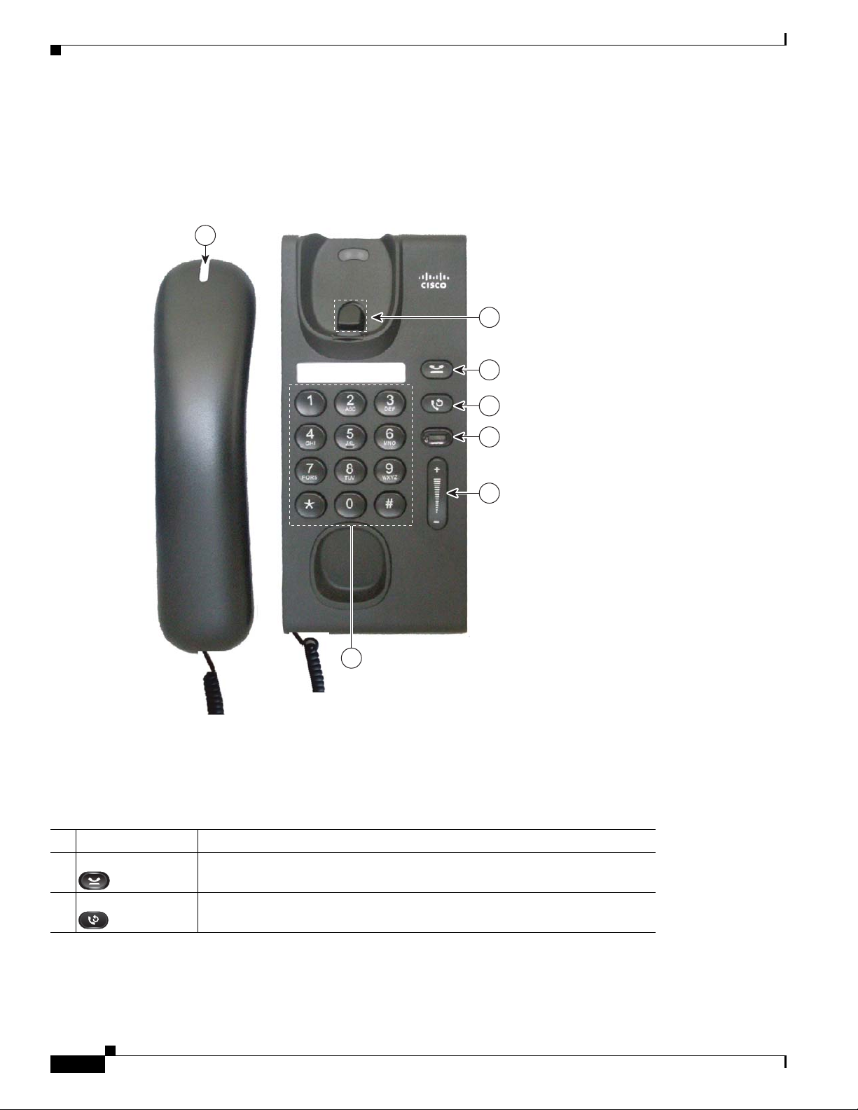
Figure 1-1 shows the main components of the Cisco Unified IP Phone 6901.
Figure 1-1 Cisco Unified IP Phone 6901
7
1
2
3
4
+
6
Table 1-1 describes the buttons on the Cisco Unified IP Phone 6901.
Ta b l e 1-1 Features on the Cisco Unified IP Phone 6901
1 Hookswitch Activates the features (hookflash) on your phone.
2 Hold button Places an active call on hold.
5
195793
3 Redial button
Cisco Unified IP Phone 6901 and 6911 Administration Guide for Cisco Unified Communications Manager 8.5 (SCCP and SIP)
1-2
Dials the last dialed number.
OL-23874-01
Page 15

Chapter 1 An Overview of the Cisco Unified IP Phone
Understanding the Cisco Unified IP Phone 6901 and 6911
4 Line button Allows users to pick up second incoming call. The line button LED shows
call status.
The line button enables users to answer an incoming call and swap between
two calls on the line. The LED associated with the line button lights up to
reflect the line status.
The line button illuminates to indicate status:
• Green, steady—Active call
• Green, flashing—Held call
• Amber, flashing—Incoming call
• Amber, steady—Call Forward All activated
• Red, steady—Remote line in use (sha red li ne)
• Red, flashing—Remote line on hold
5 Volume button Controls the handset and the ringer volume (on-hook).
6 Keypad Allows you to dial phone numbers, *, and #, and choose menu items (by
entering the item number).
7 Handset light strip Lights up to indicate a ringing call (flashing red) or a new voice message
(steady red).
OL-23874-01
Cisco Unified IP Phone 6901 and 6911 Administration Guide for Cisco Unified Communications Manager 8.5 (SCCP and SIP)
1-3
Page 16
Understanding the Cisco Unified IP Phone 6901 and 6911
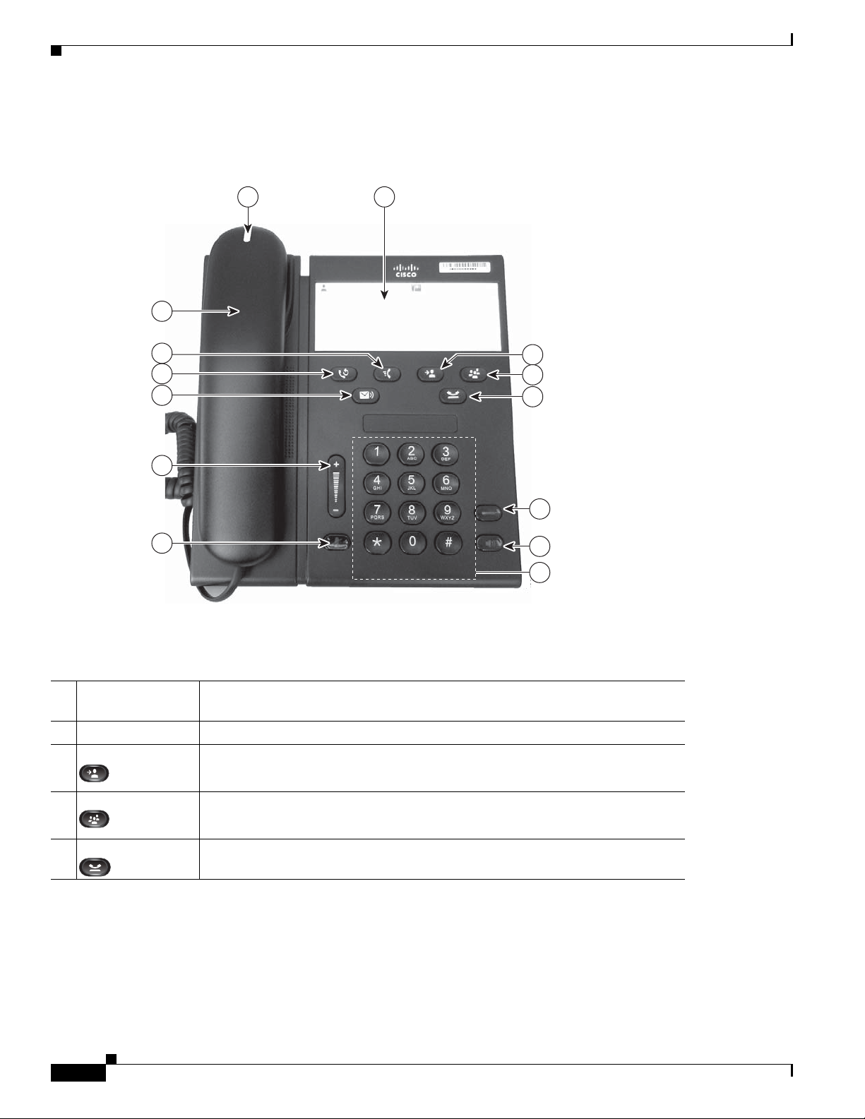
Figure 1-2 shows the main components of the Cisco Unified IP Phone 6911.
Figure 1-2 Cisco Unified IP Phone 6911
1 2
14
Chapter 1 An Overview of the Cisco Unified IP Phone
13
12
11
3
4
5
10
6
9
+
7
8
195778
Table 1-2 describes the buttons on the Cisco Unified IP Phone 6911.
Ta b l e 1-2 Features on the Cisco Unified IP Phone 6911
1 Handset light strip Lights up to indicate a ringing call (flashing red) or a new voice messag e (steady
red).
Phone Template A paper strip where you can enter names and contact numbers.
2
3 Transfer button Transfers a call.
4 Conference button Creates a conference call.
5 Hold button Places an active call on hold.
Cisco Unified IP Phone 6901 and 6911 Administration Guide for Cisco Unified Communications Manager 8.5 (SCCP and SIP)
1-4
OL-23874-01
Page 17

Chapter 1 An Overview of the Cisco Unified IP Phone
Understanding the Cisco Unified IP Phone 6901 and 6911
6 Line button Allows users to pick up an incoming call. The line button LED shows call status.
The line button enables users to answer an incoming call and swap between two
calls on the line. The LED associated with the line button lights up to reflect the
line status.
The line button illuminates to indicate status:
• Green, steady—Active call
• Green, flashing—Held call
• Amber, flashing—Incoming call
• Amber, steady—Call Forward All activated
• Red, steady—Remote line in use (sha red li ne)
• Red, flashing—Remote line on hold
7 Speakerphone
button
8 Keypad Allows you to dial phone numbers, *, and #, and choose menu i tems (by enteri ng
9 Mute button Toggles the microphone on or off. When the microphone is muted, the button is
Selects the speakerphone as the default audio path and initiates a new call, picks
up an incoming call, or ends a call. During a call, the button is lit green. The
speakerphone audio path does not change until a new default audio path is
selected (for example, by picking up the handset).
the item number).
lit red.
10 Volume button Controls the handset and speakerphone volume (of f-hook) and the ringer vol ume
(on-hook).
11 Messages button Auto-dials your voice messaging service (varies by service).
12 Redial Dials the last dialed number.
13 Feature button Depending on how the phone is set up in Cisco Unified Communications
Manager, the programmabl e feature button provides access to the Speed dialing,
Call Forward, Pickup, Group Pickup, and Meet Me features. Users can configure
up to nine items on the feature key. The user accesses each of these features by
pressing the feature key followed by the number associated with the feature. The
number must be pressed within five seconds of pressing the feature key. The
number can only be a single digit number from 1-9.
These features can be accessed off-hook or on-hook.
• Call Forward—Allows you to forward a call.
• Pickup—Allows you to pickup a call on the third-party phone.
• Group Pickup—Allows you to pick up a call within a group.
• Meet Me—Allows you to setup a conference.
• Speed Dial—Allows you to dial a specific number that has been previou sly
stored.
OL-23874-01
Cisco Unified IP Phone 6901 and 6911 Administration Guide for Cisco Unified Communications Manager 8.5 (SCCP and SIP)
1-5
Page 18

Chapter 1 An Overview of the Cisco Unified IP Phone
What Networking Protocols are Used?
14 Handset Phone handset.
What Networking Protocols are Used?
Cisco Unified IP Phones support several industry-standard and Cisco networking protocols required for
voice communication.
Cisco Unified IP Phone 6901 and 6911 support.
Ta b l e 1-3 Supported Networking Protocols on the Cisco Unified IP Phone
Networking Protocol Purpose Usage Notes
Cisco Audio Session
Tunneling (CAST)
(Cisco Unified IP Phone
6911 only)
Cisco Discovery Protocol
(CDP)
Dynamic Host
Configuration Protocol
(DHCP)
Hypertext Transfer
Protocol (HTTP)
The CAST protocol allows IP phones and
associated applications behind the phone
to discover and communicate with the
remote endpoints without requiring
changes to the traditional signaling
components like Cisco Unified
Communications Manager and g ateways.
The CAST protocol allows separate
hardware devices to synchronize related
media and it allows PC applications to
augment non Video capable phones to
become video enabled by using the PC as
the video resource.
CDP is a device-discovery protocol that
runs on all Cisco-manufactured
equipment.
Using CDP, a device can advertise its
existence to other devices and receive
information about other devices in the
network.
DHCP dynamically allocates and assigns
an IP address to network devices.
DHCP enables you to connect an IP phone
into the network and have the phone
become operational without your needing
to manually assign an IP address or to
configure additional network parameters.
HTTP is the standard way of transferring
information and moving documents across
the Internet and the web.
Table 1-3 provides an overview of the networking protocols that the
—
The Cisco Unified IP Phone uses CDP to
communicate information such as auxiliary VLAN ID,
per port power management details, and Quality of
Service (QoS) configuration information with the
Cisco Catalyst switch.
DHCP is enabled by default. If disabled, you must
manually configure the IP address, subnet mask,
gateway, and a TFTP server on each phone locally.
Cisco recommends that you use DHCP custom
option 150. With this method, you configure the
TFTP server IP address as the option value. For
additional supported DHCP configurations, go to
the
Dynamic Host Configuration Protocol chapter
and the Cisco TFTP chapter in the Cisco Unified
Communications Manager System Guide.
Note If you cannot use option 150, you may try
using DHCP option 66.
Cisco Unified IP Phones use HTTP for
troubleshooting purposes.
1-6
Cisco Unified IP Phone 6901 and 6911 Administration Guide for Cisco Unified Communications Manager 8.5 (SCCP and SIP)
OL-23874-01
Page 19

Chapter 1 An Overview of the Cisco Unified IP Phone
What Networking Protocols are Used?
Table 1-3 Supported Networking Protocols on the Cisco Unified IP Phone (continued)
Networking Protocol Purpose Usage Notes
IEEE 802.1X The IEEE 802.1X standard defines a
client-server-based access control and
authentication protocol that restricts
unauthorized clients from connecting to a
LAN through publicly accessible ports.
Until the client is authenticated, 802.1X
access control allows only Extensible
Authentication Protocol over LAN
(EAPOL) traffic through the port to which
the client is connected. After
authentication is successful, normal traffic
can pass through the port.
Internet Protocol (IP) IP is a messaging protocol that addresses
and sends packets across the network.
Link Layer Discovery
Protocol (LLDP)
(Cisco Unified IP Phone
LLDP is a standardized network discovery
protocol (similar to CDP) that is supported
on some Cisco and third-party devices.
6911 only)
Link Layer Discovery
Protocol-Media Endpoint
LLDP-MED is an extension of the LLDP
standard developed for voice products.
Devices (LLDP-MED)
The Cisco Unified IP Phone implements the IEEE
802.1X standard by providing suppo rt for the
following authentication methods: EAP-FAST and
EAP-TLS.
When 802.1X authentication is enabled on the
phone, you should disable the voice VLAN. Refer to
the
“Supporting 802.1X Authentication on Cisco
Unified IP Phones” section on page 1-17 for
additional information.
To communicate using IP, network devices must
have an assigned IP address, subnet, and gatewa y.
IP addresses, subnets, and gateways identificati ons
are automatically assigned if you are using the
Cisco Unified
IP Phone with Dynamic Host
Configuration Protocol (DHCP). If you are not
using DHCP, you must manually assign these
properties to each phone locally.
The Cisco Unified IP Phone supports LLDP on the
switch and PC port.
The Cisco Unified IP Phone supports LLDP-MED
on th e S W p o r t t o communicate information such as:
• Voice VLAN configuration
• Device discovery
Real-Time Transport
Protocol (RTP)
Real-Time Control
Protocol (RTCP)
Cisco Unified IP Phone 6901 and 6911 Administration Guide for Cisco Unified Communications Manager 8.5 (SCCP and SIP)
OL-23874-01
RTP is a standard protocol for transporting
real-time data, such as interactive voice
and video, over data networks.
RTCP works in conjunction with RTP to
provide QoS data (such as jitter, latency,
and round trip delay) on RTP streams.
• Power management
• Inventory management
For more information about LLDP-MED support,
see the LLDP-MED and Cisco Discovery Protocol
white paper:
http://www.cisco.com/en/US/technologies/tk652/tk
701/technologies_white_paper0900aecd804cd46d.
html
Cisco Unified IP Phones use the RTP protocol to
send and receive real-time voice traffic from other
phones and gateways.
RTCP is disabled by default, but you can enable it
on a per phone basis by using Cis co
Unified
Communications Manager.
1-7
Page 20

Chapter 1 An Overview of the Cisco Unified IP Phone
What Networking Protocols are Used?
Table 1-3 Supported Networking Protocols on the Cisco Unified IP Phone (continued)
Networking Protocol Purpose Usage Notes
Session Initiation Protocol
(SIP)
Skinny Client Control
Protocol (SCCP)
Transmission Control
Protocol (TCP)
Transport Layer Security
(TLS)
Trivial File Transfer
Protocol (TFTP)
SIP is the Internet Engineering T ask Force
(IETF) standard for multimedia
conferencing over IP. SIP is an
ASCII-based application-layer control
protocol (defined in RFC 3261) that can be
used to establish, maintain, and terminate
calls between two or more endpoints.
SCCP includes a messaging set that allows
communications between call control
servers and endpoint clients such as IP
Phones. SCCP is proprietary to Cisco
Systems.
TCP is a connection-oriented transport
protocol.
TLS is a standard protocol for securing
and authenticating communications.
TFTP allows you to transfer files over the
network.
On the Cisco Unified IP Phone, TFTP
enables you to obtain a configuration file
specific to the phone type.
Like other VoIP protocols, SIP is designed to
address the functions of signaling and session
management within a packet telephony network.
Signaling allows call information to be carried
across network boundaries. Session management
provides the ability to control the attributes of an
end-to-end call.
Y ou can configure the Ci sco Unified IP Phone to use
either SIP or Skinny Client Control Protocol
(SCCP).
Cisco Unified IP Phone 6901 and 6911 use SCCP,
version 20 for call control.
Cisco Unified IP Phones use TCP to connect to
Cisco Unified Communicati ons Mana ger.
When security is implemented, Cisco
Unified
IP Phones use the TLS protocol when
securely registering with Cisco
Unified
Communications Manager.
For more information, refer to the Cisco Unified
Communications Manager Security Guide.
TFTP requires a TFTP server in your network,
which can be automatically identified from the
DHCP server. If you want a phone to use a TFTP
server other than the one specified by the DHCP
server, you must manually assign the IP address of
the TFTP server by using the Network
Configuration menu on the phone.
User Datagram Protocol
(UDP)
Related Topics
• Understanding Interactions with Other Cisco Unified IP Telephony Products, page 2-1
• Understanding the Phone Startup Process, page 2-6
Cisco Unified IP Phone 6901 and 6911 Administration Guide for Cisco Unified Communications Manager 8.5 (SCCP and SIP)
1-8
UDP is a connectionless messaging
protocol for delivery of data packets.
For more information, go to the Cisco TFTP chapter
in the Cisco Unified Communications Manager
System Guide.
Cisco Unified IP Phones transmit and receive RTP
streams, which utilize UDP.
OL-23874-01
Page 21

Chapter 1 An Overview of the Cisco Unified IP Phone
What Features are Supported on the Cisco Unified IP Phone 6901 and 6911?
What Features are Supported on the Cisco Unified
Phone 6901 and 6911?
IP
Cisco Unified IP Phones function much like a digital business phone, allowing you to place and receive
phone calls. In addition to traditional telephony features, the Cisco Unified IP Phone includes features
that enable you to administer and monitor the phone as a network device.
This section includes the following topics:
• Feature Overview, page 1-9
• Configuring Telephony Features, page 1-9
• Configuring Network Parameters Using the Cisco Unified IP Phone, page 1-10
• Providing Users with Feature Information, page 1-10
Feature Overview
Cisco Unified IP Phones provide traditional telephony functionality, such as call forwarding and
transferring, redialing, confer ence calling , and voice messaging system access. Cisco
also provide a variety of other features. For an overview of the telephony features that the
Cisco
Unified IP Phone supports and for tips on configuring them, see the “Telephony Features
Available for the Cisco Unified IP Phone” se ction on page 5-1.
As with other network devices, you must configure Cisco Unified IP Phones to prepare them to access
Cisco
Unified Communications Manager and the rest of the IP network. By using DHCP, you have fewer
settings to configure on a phone, but if your network requires it, you can manually configure an IP
address, TFTP server, subnet information, and so on. For instructions on configuring the network
settings on the Cisco
Phone.”
Finally, because the Cisco Unified IP Phone is a network device, yo u can ob tain det ailed status
information from it directly. This information can assist you with troubleshooting any problems users
might encounter when using their IP phones.
Unified IP Phones, see Chapter 4, “Configuring Settings on the Cisco Unified IP
Unified IP phones
Related Topics
• Configuring Settings on the Cisco Unified IP Phone, page 4-1
• Configuring Features, Templates, Services, and Users, page 5-1
• Troubleshooting and Maintenance, page 7-1
Configuring Telephony Features
You can modify additional settings for the Cisco Unified IP Phone from Cisco Unified Communications
Manager Administration. Use Cisco Unified Communications Manager Administration to set up phone
registration criteria and calling search spaces, among other tasks. See the
for the Cisco Unified IP Phone” section on page 5-1 and the Cisco Unified Communications Manager
documentation for additional information.
Cisco Unified IP Phone 6901 and 6911 Administration Guide for Cisco Unified Communications Manager 8.5 (SCCP and SIP)
OL-23874-01
“T elephony Features A vailable
1-9
Page 22

Chapter 1 An Overview of the Cisco Unified IP Phone
Understanding Security Features for Cisco Unified IP Phones
For more information about Cisco Unified Communications Manager Administration, refer to
Cisco
Unified Communications Manager documentation, including Cisco Unified Communications
Manager Administration Guide. You can also use the context-sensitive help available within the
application for guidance.
You can access Cisco Unified Communications Manager documentation at this location:
http://www.cisco.com/en/US/products/sw/voicesw/ps556/tsd_products_support_series_home.html
You can access Cisco Unified Communications Manager Business Edition documentation at this
location:
http://www.cisco.com/en/US/products/ps7273/tsd_products_support_series_home.html
Related Topic
• Telephony Features Available for the Cisco Unified IP Phone, page 5-1
Configuring Network Parameters Using the Cisco Unified IP Phone
Y ou configure parameters such as DHCP, TFTP , and IP setting s on the phone itself. For more information
about configuring settings and viewing statistics from the phone, see
on the Cisco Unified IP Phone”.
Chapter 4, “Configuring Settings
Providing Users with Feature Information
If you are a system administrator, you ar e likely th e pr imary source of in for mation for Ci sco Unified IP
Phone users in your network or company. To ensure that you distribute the most current feature and
procedural information, familiarize yourself with Cisco
Cisco
Unified IP Phone web site:
http://www.cisco.com/en/US/products/ps10326/tsd_products_support_series_home.html
From this site, you can view various user documentation.
In addition to providing documentation, it is important to inform users of available Cisco Unified IP
Phone features—including those specific to your company or network—and of how to access and
customize those features, if appropriate.
For a summary of some of the key information that phone users need their system administrators to
provide, see
Appendix A, “Providing Information to Users Via a Website.”
Unified IP Phone documentation on the
Understanding Security Features for Cisco Unified IP Phones
Implementing security in the Cisco Unified Communications Manager system prevents identity theft of
the phone and Cisco
call signaling and media stream tampering.
To alleviate these threats, the Cisco IP telephony network establishes and maintains authenticated and
encrypted communication streams between a phone and the server, digitally signs files before they are
transferred to a phone, and encrypts media streams and call signaling between Cisco
The Cisco Unified IP Phone 6901 and 6911 use the Phone security profile, which defines whether the
device is nonsecure, authenticated, or encrypted. For information on applying the security profile to the
phone, refer to the Cisco Unified Communications Manager Security Guide.
Unified Communications Manager server, prevents data tampering, and prevents
Unified IP phones.
1-10
Cisco Unified IP Phone 6901 and 6911 Administration Guide for Cisco Unified Communications Manager 8.5 (SCCP and SIP)
OL-23874-01
Page 23

Chapter 1 An Overview of the Cisco Unified IP Phone
If you configure security-related settings in Cisco Unified Communications Manager Administration,
the phone configuration file will contain sensitive information. To ensure the privacy of a configuration
file, you must configure it for encryption. For detailed in formation, ref er to the “Confi guring Encrypted
Phone Configuration Files” chapter in Cisco Unified Communications Manager Security Guide.
Understanding Security Features for Cisco Unified IP Phones
OL-23874-01
Cisco Unified IP Phone 6901 and 6911 Administration Guide for Cisco Unified Communications Manager 8.5 (SCCP and SIP)
1-11
Page 24

Chapter 1 An Overview of the Cisco Unified IP Phone
Understanding Security Features for Cisco Unified IP Phones
Table 1-4 shows where you can find additional information about security in this and other documents.
Ta b l e 1-4 Cisco Unified IP Phone and Cisco Unified Communications Manager Security Topics
Topic Reference
Detailed explanation of security, including set up,
configuration, and troubleshooting information for Cisco
Unified
Communications Manager and Cisco Unified IP
Phones
Security features supported on the Cisco Unified IP Phone See the “Overview of Supported Security Features” section on
Viewing a security profile name See the Table 1-5 for an overview of the security features
Identifying phone calls for which security is implemented See the “Identifying Authenticated, Encrypted, and Protected
TLS connection • See the “What Networking Protocols are Used?” section
Refer to the Troubleshooting Guide for Cisco Unified
Communications Manager
page 1-13
supported by the Cisco Unified IP Phone 6901 and 6911. For
more information about these features and about Cisco Unified
Communications Manager and Cisco Unified IP Phone
security, refer to the Cisco Unified Communications Manager
Security Guide.
Phone Calls” section on page 1-15
on page 1-6
• See the “Adding Phones to the Cisco Unified
Communications Manager Database” section on page 2-7
Security and the phone startup process See the “Understanding the Phone Startup Process” section on
page 2-6
Security and phone configuration files See the “Adding Phones to the Cisco Unif ied Communications
Manager Database” section on page 2-7
Disabling access to a phone’s web pages See the “Disabling and Enabling W eb Page Access” section on
page 6-3
Troubleshooting • See the “Troubleshooting and Maintenance” section on
page 7-1
• Refer to the Troubleshooting Guide for Cisco Unified
Communications Manager
Deleting the CTL file from the phone See the “Resetting or Restoring the Cisco Unified IP Phone”
section on page 7-10
Resetting or restoring the phone See the “Resetting or Restoring the Cisco Unified IP Phone”
section on page 7-10
802.1X Authentication for Cisco Unified IP Phones See these sections:
• “Supporting 802.1X Authentication on Cisco Unified IP
Phones” section on page 1-17
• “Troubleshooting and Maintenance” section on page 7-1
1-12
Cisco Unified IP Phone 6901 and 6911 Administration Guide for Cisco Unified Communications Manager 8.5 (SCCP and SIP)
OL-23874-01
Page 25

Chapter 1 An Overview of the Cisco Unified IP Phone
Understanding Security Features for Cisco Unified IP Phones
Overview of Supported Security Features
Table 1-5 provides an overview of the security feature s that the Cisco Unified IP Phone 6901 and 6911
support. For more information about these features and about Cisco Unified Communications Manager
and Cisco
Note Most security features are available only if a certificate trust list (CTL) is installed on the phone. For
more information about the CTL, refer to “Configuring the Cisco CTL Client ” chapter in Cisco U ni fied
Communications Manager Security Guide.
Ta b l e 1-5 Overview of Security Features
Feature Description
Image authentication Signed binary files (with the extension .zz.sgn) prevent tampering with the firmware
Customer-site certificate installation Each Cisco Unified IP Phone requires a unique certificate for device authentication.
Device authentication Occurs between the Cisco Unified Communications Manager server and the phone
File authentication Validates digitally signed files that the phone downloads. The phone validates the
Signaling Authentication Uses the TLS protocol to validate that no tampering has occurred to signaling
Manufacturing installed certificate Each Cisco Unified IP Phone contains a unique manufacturing installed certificate
Unified IP Phone security, refer to Cisco Unified Communications Manager Security Guide.
image before it is loaded on a phone. Tampering with the image causes a phone to
fail the authentication pr ocess and reject the new image.
Phones include a manufacturing installed certificate (MIC), but for additional
security, you can specify in Cisco Unified
Communications Manager
Administration that a certificate be installed by using the Certificate Authority
Proxy Function (CAPF). See the
“Configuring Security on the Cisco Unified IP
Phone” section on page 3-10 for more information.
when each entity accepts the certificate of the other entity. Determines whether a
secure connection between the phone and a Cisco Unified Communications
Manager should occur; and, if necessary , creates a secure signaling path between the
entities by using TLS protocol. Cisco Unified Communications Manager will not
register phones unless they can be authenticated by the Cisco
Unified
Communications Manager.
signature to make sure that file tampering did not occur after the file creation. Files
that fail authentication are not written to Flash memory on the phone. The phone
rejects such files without further processing.
packets during transmission.
(MIC), which is used for device authentication. The MIC is a permanent unique
proof of identity for the phone, and allow s Cisco Unified Communi cations Manager
to authenticate the phone.
OL-23874-01
Cisco Unified IP Phone 6901 and 6911 Administration Guide for Cisco Unified Communications Manager 8.5 (SCCP and SIP)
1-13
Page 26

Chapter 1 An Overview of the Cisco Unified IP Phone
Understanding Security Features for Cisco Unified IP Phones
Table 1-5 Overview of Security Features (continued)
Feature Description
Secure SRST reference After you configure a SRST reference for security and then reset the dependent
devices in Cisco Unified Commu nications M anager Ad ministrati on, the TF TP
server adds the SRST certificate to the phone configuration file and sends the file to
the phone. A secure phone then uses a TLS connection to interact with the
SRST-enabled router.
The configuration file is with one of the following extensions:
• .cnf.xml
• .cnf.xml.sgn
• .cnf.xml.enc.sgn
Media encryption Uses SRTP to ensure that the media streams between supported devices proves
secure and that only the intended device receives and reads the data. Includes
creating a media master key pair for the devices, delivering the keys to the devices,
and securing the delivery of the keys while the keys are in transport.
Signaling encryption Ensures that all SCCP and SIP signaling messages that are sent between the device
and the Cisco Unified Communications Manager server are encrypted.
CAPF (Certificate Authority Proxy
Function)
Security profiles Defines whether the phone is nonsecure, authenticated, encrypted, or protected. See
Encrypted configuration files Lets you ensure the privacy of phone configuration files.
Optional disabling of the web server
functionality for a phone
Phone hardening Additi onal security option, which y ou co ntrol fro m Cisco Unified Comm unicati ons
802.1X Authentication The Cisco Unified IP Phone can use 802.1X authentication to request and gain
Voice Quality Metrics
MOS LQK Objective estimate of the Mean Opinion Score (MOS) for Listening Quality (LQK)
Implements parts of the certificate generation procedure that are too
processing-intensive for the phone, and interacts with the phone for key generation
and certificate installation. The CAPF can be configured to request certificates from
customer-specified certificate authorities on behalf of the phone, or it can be
configured to generate certificates locally.
the
“Understanding Security Profiles” section on page 1-15 for more information.
You can prevent access to a phone’s web page, which displays a variety of
operational statistics for the phone.
Manager Administration:
• Disabling access to web pages for a phone
access to the network. See the
“Supporting 802.1X Authentication on Cisco Unified
IP Phones” section on page 1-17 for more information.
that ranks audio quality from 5 (excellent) to 1 (bad). This score is based on
audible-concealment events due to a frame loss in the preceding 8 seconds of the
voice stream.
Note The MOS LQK score can vary based on the type of codec t hat the
Cisco
Unified IP Phone uses.
Avg MOS LQK Average MOS LQK score for the entire voice stream.
Min MOS LQK Lowest MOS LQK score from the start of the voice stream.
Cisco Unified IP Phone 6901 and 6911 Administration Guide for Cisco Unified Communications Manager 8.5 (SCCP and SIP)
1-14
OL-23874-01
Page 27

Chapter 1 An Overview of the Cisco Unified IP Phone
Understanding Security Features for Cisco Unified IP Phones
Table 1-5 Overview of Security Features (continued)
Feature Description
Max MOS LQK Baseline or highest MOS LQK score from the start of the voice stream.
The following codecs provide the corresponding maximum MOS LQK scores under
normal conditions with no frame loss:
• G.711: 4.5
• G.728/iLBC: 3.9
• G729A/AB: 3.7
MOS LQK Version Version of the Cisco-proprietary algorithm used to calculate the MOS LQK scores.
Related Topics
• Understanding Security Features for Cisco Unified IP Phones, page 1-10
• Identifying Authenticated, Encrypted, and Protected Phone Calls, page 1-15
Understanding Security Profiles
All Cisco Unified IP Phones that support Cisco Unified Communications Manager use a security profile,
which defines whether the phone is nonsecure, authenticated, or encrypted. For information about
configuring the security profile and applying the profile to the phone, refer to Cisco Unified
Communications Manager Security Guide.
To view the security mode that is set for the phone, you can view the security profile in Cisco Unified
Communications Manager Administration.
Related Topics
• Identifying Authenticated, Encrypted, and Protected Phone Calls, page 1-15
Identifying Authenticated, Encrypted, and Protected Phone Calls
In an authenticated call, all devices participat ing in the establishment of the call are trusted devices, and
authenticated by Cisco
In an encrypted call, all devices participating in the establishment of the call are trusted devices, and
authenticated by Cisco
are encrypted. An encrypted call offers a high level of security, providing integrity and privacy to the
call.
If the call is routed through non-IP call legs, for example, PSTN, the call may be nonsecure even though
it is encrypted within the IP network.
In a protected call, a security tone plays at the beginning of a call to indicate that the other connected
phone is also receiving and transmitting encrypted audio and video (if video is involved). If your call is
connected to a non-protected phone, the security tone does not play.
Unified Communications Manager.
Unified Communications Manager. In addition, call signaling and medi a streams
OL-23874-01
Note Protected calling is supported for connections between two phones only. Some features, such as
conference calling and shared lines are not available when protected calling is configured. Protected
calls are not authenticated.
Cisco Unified IP Phone 6901 and 6911 Administration Guide for Cisco Unified Communications Manager 8.5 (SCCP and SIP)
1-15
Page 28

Understanding Security Features for Cisco Unified IP Phones
Related Topic
• Understanding Security Features for Cisco Unified IP Phones, page 1-10
• Understanding Security Features for Cisco Unified IP Phones, page 1-10
Establishing and Identifying Protected Calls
A protected call is established when your phone, and the phone on the other end, is configured for
protected calling. The other phone can be in the same Cisco IP network, or on a network outside the IP
network. Protected calls can only be made between two phones. Conference calls and other mult iple-line
calls are not supported.
A protected call is established using this process:
1. A user initiates the ca ll from a protected phone (protected security mode).
2. A security tone plays if the call is connected to another protected phone, indicating that both ends
of the conversation are encrypted and protected. If the call is connected to a non-protected phone,
then the secure tone is not played.
Chapter 1 An Overview of the Cisco Unified IP Phone
Note Protected calling is supported for conversations between two phones. Some features, such as conference
calling and shared lines are not available when protected calling is configured.
Call Security Interactions and Restrictions
Cisco Unified Communication s Manage r checks the phone security status when conferences are
established and changes the security indication for the conference or blocks the completion of the call
to maintain integrity and also security in the system.
Table 1-6 provides information about changes to call security levels when using Barge for Cisco Unified
IP Phone 6901 and 6911.
Ta b l e 1-6 Call Security Interactions When Using Barge (Cisco Unified IP Phone 6911 only)
Initiator’s Phone
Security Level
Non-secure cBarge Encrypted call Call barged and identified as non-secure call
Secure (encrypted) cBarge Authenticated call Call barged and identified as authenticated call
Secure
(authenticated)
Non-secure cBarge Authenticated call Call barged and identified as non-secure call
Feature Used Call Security Level Results of Action
cBarge Encrypted call Call barged and identified as authenticated call
1-16
Table 1-7 provides information about changes to conference security levels dependin g on the in itiat or’s
phone security level, the security levels of participants, and the availability of secure conference bridges.
Cisco Unified IP Phone 6901 and 6911 Administration Guide for Cisco Unified Communications Manager 8.5 (SCCP and SIP)
OL-23874-01
Page 29

Chapter 1 An Overview of the Cisco Unified IP Phone
Understanding Security Features for Cisco Unified IP Phones
Ta b l e 1-7 Security Restrictions with Conference Calls
Initiator’s Phone
Security Level
Non-secure Conference Encrypted or authenticated Non-secure conference bridge
Secure (encrypted
or authenticated)
Secure (encrypted) Conference All participants are encrypted Secure encrypted level conference
Secure
(authenticated)
Non-secure cBarge All participants are encrypted Conference changes to non-secure
Non-secure Meet Me Minimum security level is
Secure (encrypted) Meet Me Minimum security level is
Secure (encrypted) Meet Me Minimum security level is
Feature Used Security Level of Participants Results of Action
Non-secure conference
Conference At least one member is
non-secure
Conference All participants are encrypted or
authenticated
encrypted
authenticated
non-secure
Non-secure conference
Secure authenticated level conference
Initiator receives message “Does not meet Security
Level”, call rejected.
Conference accepts encrypted and authenticated
calls
Only secure conference bridge available and used
Conference accepts all calls
Supporting 802.1X Authentication on Cisco Unified IP Phones
These sections provide information about 802.1X support on the Cisco Unified IP Phones:
• Overview, page 1-17
• Required Network Components, pa ge 1-18
• Best Practices—Requirements and Recommendations, page 1-19
Overview
Cisco Unified IP phones and Cisco Catalyst switches have traditionally used Cisco Discovery Protocol
(CDP) to identify each other and determine parameters such as VLAN allocation and inline power
requirements. However, CDP is not used to identify any locally attached PCs; therefore, Cisco Unified
IP Phones provide an EAPOL pass-through mechanism, whereby a PC locally attached to the IP phone,
may pass through EAPOL messages to the 8 02.1X auth enticator in the LAN switch. This prevents the
IP phone from having to act as the authent icator, yet allows the LAN switch to authenticate a data end
point prior to accessing the network.
In conjunction with the EAPOL pass-through mechanism, Cisco Unified IP Phones provide a proxy
EAPOL-Logoff mechanism. In the event that the locally attached PC is disconnected from the IP phone,
the LAN switch would not see the physical link fail, because the link between the LAN switch and the
IP phone is maintained. T o avoid compromising network in tegrity , the IP phone sends an EAPOL-Logof f
message to the switch, on behalf of the downstream PC, which triggers the LAN switch to clear the
authentication entry for the downstream PC.
OL-23874-01
The Cisco Unified IP phones also contain an 802.1X supplicant , in additio n to the EA POL pass-through
mechanism. This supplicant allows network administrators to control the connectivity of IP phones to
the LAN switch ports. The current release of the phone 802.1X supplicant uses the EAP-FAST and
EAP-TLS options for network authentication.
Cisco Unified IP Phone 6901 and 6911 Administration Guide for Cisco Unified Communications Manager 8.5 (SCCP and SIP)
1-17
Page 30

Understanding Security Features for Cisco Unified IP Phones
Required Network Components
Support for 802.1X authentication on Cisco Unified IP Phones requires several components, including:
• Cisco Unified IP Phone—The phone acts as the 802.1X supplicant, which initiates the request to
access the network.
• Cisco Secure Access Control Server (ACS) (or other third-party authentication server)—The
authentication server and the phone must both be configured with a shared secret that is used to
authenticate the phone.
• Cisco Catalyst Switch (or other third-party switch)—The switch must support 802.1X, so it can act
as the authenticator and pass the messages between the phone and the authentication server. When
the exchange is completed, the switch then grants or denies the phone access to the network.
Chapter 1 An Overview of the Cisco Unified IP Phone
1-18
Cisco Unified IP Phone 6901 and 6911 Administration Guide for Cisco Unified Communications Manager 8.5 (SCCP and SIP)
OL-23874-01
Page 31

Chapter 1 An Overview of the Cisco Unified IP Phone
Best Practices—Requirements and Recommendations
• Enable 802.1X Authentication—If you want to use the 802.1X standard to authenticate Cisco
Unified IP Phones, be sure that you have properly configured th e other components before enab ling
it on the phone.
• Configure PC Port—The 802.1X standard does not take into account the use of VLANs and thus
recommends that only a single device should be authenticated to a specific switch port. However,
some switches (including Cisco Catalyst switches) support multi-domain authentication. The switch
configuration determines whether you can connect a PC to the phone’s PC port.
Note Only Cisco Unified IP Phone 6911 has PC ports.
–
Enabled—If you are using a switch that supports multi-domain authentication, you can enable
the PC port and connect a PC to it. In this case, Cisco Unified IP Phones support proxy
EAPOL-Logoff to monitor the authentication exchanges between the switch and the attached
PC. For more information about IEEE 802.1X support on the Cisco Catalyst switches, refer to
the Cisco Catalyst switch configuration guides at:
http://www.cisco.com/en/US/products/hw/switches/ps708/tsd_products_support_series_home.
html
–
Disabled—If the switch does not suppor t multi ple 802 .1X- compli ant devices on the same port ,
you should disable the PC Port when 802.1X authentication is enabled. If you do not disable
this port and subsequently attempt to attach a PC to it, the switch will deny network access to
both the phone and the PC.
• Configure Voice VLAN—Because the 802.1X standard does not account for VLANs, you should
configure this setting based on the switch support.
Overview of Configuring and Installing Cisco Unified IP Phones
–
Enabled—If you are using a switch that supports multi-domain authenticatio n, you can continue
to use the voice VLAN.
–
Disabled—If the switch does not support multi-domain authentication, di sable the Voice VLAN
and consider assigning the port to the native VLAN.
Overview of Configuring and Installing Cisco Unified IP Phones
When deploying a new IP telephony system, system administrators and network administrators must
complete several initial configuration tasks to prepare the network for IP
information and a checklist for setting up and configuring a Cisco IP telephony network, go to the
System Configuration Overview chapter in Cisco Unified Communications Manager System Guide.
After you have set up the IP telephony system and configured system-wide features in Cisco Unified
Communications Manager, you can add IP phones to the system.
The following topics provide an overview of procedures for adding Cisco Unified IP Phones to your
network:
• Configuring Cisco Unified IP Phones in Cisco Unified Communications Manager, page 1-20
• Installing Cisco Unified IP Phones, page 1-23
telephony service. For
OL-23874-01
Cisco Unified IP Phone 6901 and 6911 Administration Guide for Cisco Unified Communications Manager 8.5 (SCCP and SIP)
1-19
Page 32

Chapter 1 An Overview of the Cisco Unified IP Phone
Overview of Configuring and Installing Cisco Unified IP Phones
Configuring Cisco Unified IP Phones in Cisco Unified Communications Manager
To add phones to the Cisco Unified Communications Manager database, you can use:
• Auto-registration—Not supported if Cisco Unified Com munications Manager i s operating in mixed
mode.
• Cisco Unified Communications Manager Administration
• Bulk Administration Tool (BAT)
• BAT and the Tool for Auto-Registered Phones Support (TAPS)
For more information about these choices, see the “Adding Phones to the Cisco Unified
Communications Manager Database” section on page 2-7.
For general information about configuring phones in Cisco Unified Communications Manager, refer to
the following documentation:
• Cisco Unified IP Phones, Cisco Unified Communications Manager System Guide
• Cisco Unified IP Phone Configuration, Cisco Unified Communications Manager Administ ration
Guide
• Autoregistration Configuration, Cisco Unified Communications Manager Administration Guide
1-20
Cisco Unified IP Phone 6901 and 6911 Administration Guide for Cisco Unified Communications Manager 8.5 (SCCP and SIP)
OL-23874-01
Page 33

Chapter 1 An Overview of the Cisco Unified IP Phone
Overview of Configuring and Installing Cisco Unified IP Phones
Checklist for Configuring the Cisco Unified IP Phone 6901 and 6911 in Cisco Unified Communications Manager
Table 1-8 provides an overview and checklist of configuration tasks for the Cisco Unified
IP Phone 6901 and 6911 in Cisco Unified Communications Manager Administration. The list presents a
suggested order to guide you through the phone configuration process. Some tasks are optional,
depending on your system and user needs. For detailed procedures and information, refer to the sources
in the list.
Ta b l e 1-8 Checklist for Configuring the Cisco Unified IP Phone 6901 and 6911 in Cisco Unified Communications
Manager
Task Purpose For More Information
1. Gather the following information about the phone:
• Phone Model
• MAC address
• Physical location of the phone
• Name or user ID of phone user
• Device pool
• Partition, calling search space, and location
information
For more information, go to the “Cisco Unified IP
Phones chapter in the Cisco Unified Communications
Manager System Guide.
See the “Telephony Features Available for the Cisco
Unified IP Phone” section on page 5-1.
• Associated directory number (DN) to assign to the
phone
• Cisco Unified Communications Manager user to
associate with the phone
Provides list of configuration requirements for setting
up phones.
2. Verify that you have sufficient unit licenses for your
phone.
3. Add and configure the phone by completing the
required fields in the Phone Configuration window.
Required fields are indicated by an asterisk (*) next to
the field name; for example, MAC address and device
pool.
The device with its default settings gets added to the
Cisco Unified Communications Manager database.
For more information, go to the License Unit Report
chapter in the Cisco Communications Manager
Administration Guide.
For more information, go to the Cisco Unified IP Phone
Configuration chapter in the Cisco Communications
Manager Administration Guide.
For information about Product Specific Configuration
fields, refer to “?” Button Help in the Phone
Configuration window.
Note If you want to add both the phone and user to the
Cisco Unified Communications Manager
database at the same time, go to the
User/Phone
Add Configuration chapter in the
Cisco Communications Manager Administration
Guide.
OL-23874-01
Cisco Unified IP Phone 6901 and 6911 Administration Guide for Cisco Unified Communications Manager 8.5 (SCCP and SIP)
1-21
Page 34

Chapter 1 An Overview of the Cisco Unified IP Phone
Overview of Configuring and Installing Cisco Unified IP Phones
Table 1-8 Checklist for Configuring the Cisco Unified IP Phone 6901 and 6911 in Cisco Unified Communications
Manager (continued)
Task Purpose For More Information
4. Add and configure directory numbers (line) on the
phone by completing the required fields in the
Directory Number Configurati on wind ow. Required
fields are indicated by an asterisk (*) next to the field
name; for example, directory number and presence
group.
5. Add user information by configuring required fields.
Required fields are indicated by an asterisk (*); for
example, User ID and last name.
Note Assign a password (for User Options web
pages) and PIN (for accessing the Network
Menu via the IVR).
Adds user information to the global directory for
Cisco Unified
6. Associate a user to a user group.
Communications Manager.
Assigns users a common list of roles and permissions
that apply to all users in a user group. Administrators
can manage user groups, roles, and perm issions to
control the level of access (and, therefore, the level of
security) for system users.
Note In order for end users to access Cisco Unified
CM User Options, you must add users to the
standard Cisco CCM End Users group.
7. Associate a user with a phone (optional).
Provides users with control over their phone such a
forwarding calls or adding speed-dial numbers or
services.
Note Some phones, such as those in conference
rooms, do not have an associated user.
For more information, go to the “Directory Number
Configuration” chapter in the Cisco Unified
Communications Manager Administration Guide.
See the “Telephony Features Available for the Cisco
Unified IP Phone” section on page 5-1.
For more information, go to the End User Configurati on
chapter in the Cisco Unified Communications Manager
Administration Guide.
See the “Adding Users to Cisco Unified
Communications Manager” section on page 5-8.
Note If you want to add both the phone and user to the
Cisco Unified Communicatio ns Manager
database at the same time, go to the
User/Phone
Add Configurations chapter in the Cisco Unified
Communications Manager Administration
Guide.
Refer to the following sectio ns in th e Cisco U nified
Communications Manager Administration Guide:
• “End User Configuration Settings” section in the
“End User Configuration” chapter.
• “Adding Users to a User Group” section in the “User
Group Configuration” chapter.
For more information, go to the “Associating Devices to
an End User” section in the End User Configuration
chapter in the Cisco Unified Communications Manager
Administration Guide.
1-22
Cisco Unified IP Phone 6901 and 6911 Administration Guide for Cisco Unified Communications Manager 8.5 (SCCP and SIP)
OL-23874-01
Page 35

Chapter 1 An Overview of the Cisco Unified IP Phone
Installing Cisco Unified IP Phones
After you have added the phones to th e Cisco Unified Communications Manager database, you can
complete the phone installation. You (or the phone users) can install the phone at the users’s location.
Note Upgrade the phone with the current firmware image before you install the phone. For informat ion about
upgrading, refer to the Readme file for your phone, located at:
http://tools.cisco.com/support/downloads/go/Redirect.x?mdfid=278875240
For instructions on upgrading the firmware, see the Release Notes, located at:
http://www.cisco.com/en/US/products/ps10326/prod_release_notes_list.html
After the phone is connected to the network, the phone startup process begins, and the phone registers
with Cisco
settings on the phone depending on whether you enable or disable DHCP service.
If you used auto-registration, you need to update the specific configuration information for the phone
such as associating the phone with a user, changing the button table, or directory number.
Unified Communications Manager. To finish installing the phone, configure the network
Overview of Configuring and Installing Cisco Unified IP Phones
Checklist for Installing the Cisco Unified IP Phone 6901 and 6911
Table 1-9 provides an overview and checklist of installation tasks for the Cisco Unified IP Phone 6901
and 6911. The list presents a suggested order to guide you through the phone installation. Some tasks
are optional, depending on your system and user needs. For detailed procedures and information, refer
to the sources in the list.
Ta b l e 1-9 Installation Checklist for the Cisco Unified IP Phone 6901 and 6911
Task Purpose For More Information
1. Choose the power source for the phone:
• Power over Ethernet (PoE)
• External power supply
Determines how the phone receives power.
2. Assemble the phone, adjust phone placement, and connect the
network cable.
Locates and installs the phone in the network.
3. Monitor the phone startup process.
Associates directory numbers to the phone.
Verifies that phone is configured properly.
See the “Providing Power to the Cisco Unified
IP Phone” section on page 2-3.
See the “Installing the Cisco Unified IP Phone”
section on page 3-4.
See the “Footstand” section on page 3-7.
See the “Verifying the Phone Startup Process”
section on page 3-9.
OL-23874-01
Cisco Unified IP Phone 6901 and 6911 Administration Guide for Cisco Unified Communications Manager 8.5 (SCCP and SIP)
1-23
Page 36

Chapter 1 An Overview of the Cisco Unified IP Phone
Terminology Differences
Table 1-9 Installation Checklist for the Cisco Unified IP Phone 6901 and 6911 (continued)
Task Purpose For More Information
4. If you are configuring the network settings on the phone, you
can set up an IP address for the phone by either using DHCP or
manually entering an IP address.
Using DHCP—Verify that DHCP is enabled with the IVR. Y ou
can set an alternate TFTP by entering the IP address for the
TFTP when prompted by the IVR.
Note Consult with the network administrator to determine
whether you need to assign an alternative TFTP server
instead of using the TFTP server assigned by DHCP.
Without DHCP—Verify that DHCP is disabled with the IVR.
Yo u must then configure the IP address, subnet mask, TFTP
server, and default router locally by using the phone’s IVR.
5. Set up security on the phone.
Provides protection against data tampering threats and identity
theft of phones.
6. Make calls with the Cisco Unified IP Phone.
Verifies that the phone and features work correctly.
7. Provide information to end users about how to use their ph ones
and how to configure their phone options.
See the “Configuring Startup Network
Settings” section on page 3-9.
See the “Configuring Settings on the Cisco
Unified IP Phone” se ction on pa ge 4-1.
See the “Configuring Security on the Cisco
Unified IP Phone” section on page 3-10.
Refer to Cisco Unified IP Phone 6901 and 6911
User Guide for more information.
See Appendix A, “Providing Information to
Users Via a Website.”
Ensures that users have adequate information to successful ly
use their Cisco Unified
IP Phones.
Terminology Differences
Table 1-10 highlights some of the important differences in terminology that is used in these documents:
• Cisco Unified IP Phone 6901 and 6911 User Guide for Cisco Unifi ed Communications Manager 8.5
(SCCP)
• Cisco Unified IP Phone 6901 and 6911 Administration Guide for Cisco Unified Communications
Manager 8.5 (SCCP)
• Cisco Unified Communications Manager Administration Guide
• Cisco Unified Communications Manager System Guide
Ta b l e 1-10 Termino logy Differences
User Guide Administration and System Guides
Auto Barge cBarge
Message Indicators Message Waiting Indicator (MWI) or
Voicemail System Voice Messaging System
Message Waiting Lamp
1-24
Cisco Unified IP Phone 6901 and 6911 Administration Guide for Cisco Unified Communications Manager 8.5 (SCCP and SIP)
OL-23874-01
Page 37

CHAP T E R
2
Preparing to Install the Cisco Unified IP Phone on Your Network
Cisco Unified IP Phones enable you to communicate by using voice over a data network. To provide this
capability, the IP Phones depend upon and interact with several other key Cisco
components, including Cisco
This chapter focuses on the interactions between the Cisco Unified IP Phone 6901 and 6911 and
Cisco
Unified Communications Manager, DNS and DHCP servers, TFTP servers, and switches. It also
describes options for powering phon es.
For related information about voice and IP communications, refer to this URL:
http://www.cisco.com/en/US/products/sw/voicesw/index.html
This chapter provides an overview of the interaction between the Cisco Unified IP Phone and other key
components of the Voice over IP (VoIP) network. It includes the following topics:
• Understanding Interactions with Other Cisco Unified IP Telephony Products, page 2-1
• Providing Power to the Cisco Unified IP Phone, page 2-3
• Understanding Phone Configuration Fi les, page 2-5
Unified Communications Manager.
Unified IP Telephony
• Understanding the Phone Startup Process, page 2-6
• Adding Phones to the Cisco Unified Communications Manager Database, page 2-7
• Using Cisco Unified IP Phones with Different Protocols, page 2-11
• Determining the MAC Address for a Cisco Unified IP Phone, page 2-12
Understanding Interactions with Other Cisco Unified IP Telephony Products
T o function in the IP telephony network, the Cisco Unified IP Phone must be connected to a networking
OL-23874-01
device, such as a Cisco Catalyst switch. Y ou must also register the Cisco
Unified
This section includes the following topics:
• Understanding How the Cisco Unified IP Phone Interacts with Cisco Unified Communications
• Understanding How the Cisco Unified IP Phone 6911 Interacts with the VLAN, page 2-2
Cisco Unified IP Phone 6901 and 6911 Administration Guide for Cisco Unified Communications Manager 8.5 (SCCP and SIP)
Communications Manager system before sending and receiving calls.
Manager, page 2-2
Unified IP Phone with a Cisco
2-1
Page 38

Chapter 2 Preparing to Install the Cisco Unified IP Phone on Your Network
Understanding Interactions with Other Cisco Unified IP Telephony Products
Understanding How the Cisco Unified IP Phone Interacts with Cisco Unified Communications Manager
Cisco Unified Communications Manager is an open and industry-standard call processing system.
Cisco
Unified Communications M anager softwa re sets up an d tears dow n calls bet ween phon es,
integrating traditional PBX functionality wit h the corporate IP network. Cisco
Manager manages the components of the IP telephony system—the phones, the access gateways, and the
resources necessary for features such as call conferencing and route planning. Cisco
Communications Manager also provides:
• Firmware for phones
• Configuration file via TFTP service
• Phone registration
• Call preservation, so that a media session continues if signaling is lost between the primary
Communications Manager and a phone
For information about configuring Cisco Unified Communications Manager to work with th e IP devices
described in this chapter, go to the
Cisco Communications Manager Administration Guide.
For an overview of security functionality for the Cisco Unified IP Phone, see the “Understanding
Security Features for Cisco Unified IP Phones” section on page 1-10.
Cisco Unified IP Phone Configuration chapter in the
Unified Communications
Unified
Note If the Cisco Unified IP Phone model that you want to configure does not appear in the Phone Type
drop-down list in Cisco Unified Communicati ons Manager Administration, go to th e following URL and
install the latest support patch for your version of Cisco Unified
http://tools.cisco.com/support/downloads/go/Redirect.x?mdfid=278875240
For more information, refer to “Software Upgrades” chapter in the Cisco Unified Communications
Operating System Administration Guide.
Related Topic
• Telephony Features Available for the Cisco Unified IP Phone, page 5-1
Communications Manager:
Understanding How the Cisco Unified IP Phone 6911 Interacts with the VLAN
The Cisco Unified IP Phone 6911 has an internal Et hernet swit ch, enabling forwarding o f packets to the
phone, and to the access port and the network port on the back of the phone.
Note Cisco Unified IP Phone 6901 does not support PC port.
If a computer is connected to the access port, the computer and the phone share the same physical link
to the switch and share the same port on the switch. This shared physical link has the following
implications for the VLAN configuration on the network:
2-2
• The current VLANs might be configured on an IP subnet basis. However, additional IP addresses
might not be available to assign the phone to the same subnet as other devices connected to the same
port.
Cisco Unified IP Phone 6901 and 6911 Administration Guide for Cisco Unified Communications Manager 8.5 (SCCP and SIP)
OL-23874-01
Page 39

Chapter 2 Preparing to Install the Cisco Unified IP Phone on Your Network
• Data traffic present on the VLAN supporting phones might reduce the quality of Voice-over-IP
traffic.
• Network security may indicate a need to isolate the VLAN voice traffic from the VLAN data traf fic.
You can resolve these issues by isolating the voice traffic onto a separate VLAN. The switch port that
the phone is connected to would be configured to have separate VLANs for carrying:
• Voice traffic to and from the IP phone (auxiliary VLAN on the Cisco Catalyst 6000 series, for
example)
• Data traffic to and from the PC connected to the switch through the access port of the IP phone
(native VLAN)
Isolating the phones on a separate, auxiliary VLAN increases the quality of the voice traffic and allows
a large number of phones to be added to an existing network where there are not enough IP addresses
for each phone.
For more information, refer to the documentation included with a Cisco switch. You can also access
switch information at this URL:
http://cisco.com/en/US/products/hw/switches/index.html
Related Topics
• Understanding the Phone Startup Process, page 2-6
• Configuring Settings on the Cisco Unified IP Phone, page 4-1
Providing Power to the Cisco Unified IP Phone
Providing Power to the Cisco Unified IP Phone
The Cisco Unified IP Phone 6901 and 6911 can be powered with external power or with Power over
Ethernet (PoE). External power is provided through a separate power supply . PoE is provided by a swi tch
through the Ethernet cable attached to a phone.
Note When you install a phone that is powered with external power, connect the power supply to the phone
and to a power outlet before you connect the Ethernet cable to the phone. When you remove a phone that
is powered with external power, disco nnect the Ethernet cable from the phone before you disconnect the
power supply.
The following sections provide more information about powering a phone:
• Power Guidelines, page 2-4
• Power Outage, page 2-4
• Obtaining Additional Information About Power, page 2-5
OL-23874-01
Cisco Unified IP Phone 6901 and 6911 Administration Guide for Cisco Unified Communications Manager 8.5 (SCCP and SIP)
2-3
Page 40

Chapter 2 Preparing to Install the Cisco Unified IP Phone on Your Network
Providing Power to the Cisco Unified IP Phone
Power Guidelines
Table 2-1 provides guidelines for powering the Cisco Unified IP Phone 6901 and 6911.
Ta b l e 2-1 Guidelines for Powering the Cisco Unified IP Phone 6901 and 6911
Power Type Guidelines
External power—Provided
through the CP-PWR-CUBE-3
external power supply.
External power—Provided
through the Cisco Unified IP
Phone Power Injector.
PoE power—Provided by a
switch through the Ethernet
cable attached to the phone.
The Cisco Unified IP Phone 6901 and 6911 use the CP-PWR-CUBE-3 power supply.
The Cisco Unified IP Phone Power Injector may be used with any Cisco Unified IP Phone.
Functioning as a midspan device, the injector delivers inline power to the attached phone.
The Cisco Unified IP Phone Power Injector is connected between a switch port and the IP
Phone, and supports a maximum cable length of 100m between the unpower ed switch and
the IP Phone.
• The Cisco Unified IP Phone 6901 and 6911 support Cisco inline PoE.
• The Cisco Unified IP Phone 6901 and 6911 support IEEE 802.3af Class 1 power on
signal pairs and spare pairs.
• To ensure uninterruptible operation of the phone, make sure that the switch has a
backup power supply.
External power—Provided
through inline power patch
panel WS-PWR-PANEL
Power Outage
Your accessibility to emergency service through the phone is dependent on the phone being powered. If
there is an interruption in the power supply, Service and Emergency Calling Service dialing will not
function until power is restored. In the case of a power failure or disruption, you may need to reset or
reconfigure equipment before using the Service or Emergency Calling Service dialing.
• Make sure that the CatOS or IOS version running on your switch supports your
intended phone deployment. Refer to the documentati on for your switch for operating
system version information.
The inline power patch panel WS-PWR-PANEL is compatible with the Cisco Unified
IP
Phone 6901 and 6911.
2-4
Cisco Unified IP Phone 6901 and 6911 Administration Guide for Cisco Unified Communications Manager 8.5 (SCCP and SIP)
OL-23874-01
Page 41

Chapter 2 Preparing to Install the Cisco Unified IP Phone on Your Network
Obtaining Additional Information About Power
For related information about power, refer to the documents shown in Table 2-2. These documents
provide information about the following topics:
• Cisco switches that work with the Cisco Unified IP Phone 6901 and 6911
• The Cisco IOS releases that support bidirectional power negotiation
• Other requirements and restrictions regarding power
Ta b l e 2-2 Related Documentation for Power
Document Topics URL
Cisco Unified IP Phone Power
Injector
PoE Solutions http://www.cisco.com/en/US/netsol/ns340/ns394/ns147/ns412/net
Cisco Catalyst Switches http://cisco.com/en/US/products/hw/switches/index.html
Integrated Service Routers http://www.cisco.com/en/US/products/hw/routers/index.html
Cisco IOS Software http://www.cisco.com/en/US/products/sw/iosswrel/products_ios_
http://www.cisco.com/en/US/products/ps6951/index.html
working_solutions_package.html
cisco_ios_software_category_home.html
Understanding Phone Configuration Files
Understanding Phone Configuration Files
Configuration files for a phone are stored on the TFTP server and define parameters for connecting to
Cisco Unified
Communications Manager that requires the phone to be reset, a change is automatically made to the
phone’s configuration file.
Configuration files also contain information about which i mage load the phone should be running. If this
image load differs from the one currently loaded on a phone, the phone contacts the TFTP server to
request the required load files.
In addition, if the device security mode in the configuration file is set to Auth enticated and the CTL file
on the phone has a valid certificate for Cisco
a TLS connection to Cisco
connection.
Note If the device security mode in the configuration file is set to Authenticated or Encrypted, but the phone
has not received a CTL file, the phone tries four times to obtain a CTL file so it can register securely.
If you configure security-related settings in Cisco Unified Communications Manager Administration,
the phone configuration file will contain sensitive information. To ensure the privacy of a configuration
file, you must configure it for encryption. For detailed in formation, refer to the “
Phone Configuration Files” chapter in Cisco Unified Communications Manager Security Guide. A
phone requests a configuration file whenever it resets an d registers with Cisco Unified Communications
Manager.
A phone accesses a default configuration file named XmlDefault.cnf.xml from the TFTP server when
the following conditions exist:
Communications M anager. In general, any time you make a change in Cisco Unified
Unified Communications Manager, the phone establishes
Unified Communications Manager. Otherwise, the phone establishes a TCP
Configuring Encrypted
OL-23874-01
Cisco Unified IP Phone 6901 and 6911 Administration Guide for Cisco Unified Communications Manager 8.5 (SCCP and SIP)
2-5
Page 42

Understanding the Phone Startup Process
• You have enabled auto-registration in Cisco Unified Communications Manager
• The phone has not been added to the Cisco Unified Communications Manager database
• The phone is registering for the first time
If auto registration is not enabled and the phone has not been added to the Cisco Unified
Communications Manager database, the phone registration request will be rejected.
If the phone is registered and working in encrypted mode, the phone accesses the configuration file
named SEPmac_address.cnf.xml.enc.sgn. If the SEPmac_address.cnf.xml.enc.sgn does not exist on the
TFTP server, the phone requests for the file SEPmac_address.cnf.xml.sgn. That is, if phone works in
encrypted mode with TFTP Encrypted Config selected, the phone accesses the config uration file named
SEPMac_addr.cnf.xml.enc.sgn if it is not chosen, SEPMac_addr.cnf.xml.sgn is chosen. T o enable TFTP
Encrypted Configuration, select th e TFTP Encrypted Config check box Phone Security Profile
Configuration page. You can access this page from the Cisco Unified CM Administration UI by selecting
System > Security> Phone Security Profile and then clicking Add New.
For SIP phones, the TFTP server generates these SIP configuration files:
• SIP IP Phone:
–
For unsigned and unencrypted files—SEP<mac>.cnf.xml
Chapter 2 Preparing to Install the Cisco Unified IP Phone on Your Network
–
For signed files—SEP<mac>.cnf.xml.sgn
–
For signed and encrypted files—SEP<mac>.cnf.xml.enc.sgn
• Dial Plan—<dialplan>.xml
The filenames are derived from the MAC address and description fiel ds in the Phon e Config uration
window of Cisco
Unified Communications Manager Administration. The MAC address uniquely
identifies the phone.
For more information on phone configuration settings, go to the Cisco Unified IP Phone Configuration
chapter in the Cisco Communications Manager Administration Guide.
Understanding the Phone Startup Process
When connecting to the VoIP network, the Cisco Unified IP Phone 6901 and 6911 go through a standard
startup process that is described in
of these steps may occur on your Cisco Unified IP Phone.
Ta b l e 2-3 Cisco Unified IP Phone Startup Process
Task Purpose Related Topics
1. Obtaining Power from the Switch
If a phone is not using external power, the switch provides in-line power
through the Ethernet cable attached to the phone.
2. Configuring VLAN
If the Cisco Unified IP Phone is connected to a Cisco Catalyst switch, the
switch next informs the phone of the voice VLAN defined on the switch.
The phone needs to know its VLAN membership before it can proceed with
the Dynamic Host Configuration Protocol (DHCP) request for an IP address.
Table 2-3. Depending on your specific network configuration, not all
• Adding Phones to the Cisco
Unified Communications
Manager Database, page 2-7.
• Resolving Startup Problems,
page 7-1.
• Configuring Settings on the
Cisco Unified IP Phone,
page 4-1.
• Resolving Startup Problems,
page 7-1.
2-6
Cisco Unified IP Phone 6901 and 6911 Administration Guide for Cisco Unified Communications Manager 8.5 (SCCP and SIP)
OL-23874-01
Page 43

Chapter 2 Preparing to Install the Cisco Unified IP Phone on Your Network
Adding Phones to the Cisco Unified Communications Manager Database
Table 2-3 Cisco Unified IP Phone Startup Process (continued)
Task Purpose Related Topics
3. Obtaining an IP Address
If the Cisco Unified IP Phone is using DHCP to obtain an IP address, the
phone queries the DHCP server to obtain one. If you are not us ing DHCP in
your network, you must assign static IP addresses to each phone locally.
4. Accessing a TFTP Server
In addition to assigning an IP address, the DHCP server directs the
Cisco
Unified IP Phone to a TFTP Server. If the phone has a statically
defined IP address, you must configure the TFTP server locally on the
phone; the phone then contacts the TFTP server directly.
Note You can also assign an alternative TFTP server to use instead of the
one assigned by DHCP.
5. Requesting the Configuration File
The TFTP server has configuration files, which define parameters for
connecting to Cisco Unified
information for the phone.
6. Loading the Stored Phone Image
The Cisco Unified IP Phone has non-volatile Flash memory in which it
stores firmware images and user-defined preferences. At startup, the phone
runs a bootstrap loader that loads a phone image stored in Flash memory.
Using this image, the phone initializes its software and hardware.
7. Contacting Cisco Unified Communications Manager
The configuration file defines how the Cisco Unified IP Phone
communicates with Cisco Unified
a phone with its load ID. After obtaining the file from the TFTP server, the
phone attempts to make a connection to the highest priority Cisco
Unified
If the phone was manually added to the database, Cisco
Unified
not manually added to the database and auto-registration is enabled in Cisco
Unified
in the Cisco Unified
Communications Manager on the list.
Communications Manager identifies the phone. If the phone was
Communications Manager, the phone at tempts to auto-register itself
Communications Manager database.
Communications Manager and other
Communications Manager and provides
• Configuring Settings on the
Cisco Unified IP Phone,
page 4-1.
• Resolving Startup Problems,
page 7-1.
• Configuring Settings on the
Cisco Unified IP Phone,
page 4-1.
• Resolving Startup Problems,
page 7-1.
• Adding Phones to the Cisco
Unified Communications
Manager Database, page 2-7.
• Resolving Startup Problems,
page 7-1.
Resolving Startup Problems,
page 7-1.
Resolving Startup Problems,
page 7-1.
Adding Phones to the Cisco Unified Communications Manager
Database
Before installing the Cisco Unified IP phone, you must choose a method for adding phones to the
Cisco
Unified Communications Ma nager database . Be aware that each phone type requires a fixed
number of device license units and the n umber of unit licenses that are available on the server may
impact phone registration. For more information on licensing go to the
the Cisco Unified Communications Manager System Guide
Cisco Unified IP Phone 6901 and 6911 Administration Guide for Cisco Unified Communications Manager 8.5 (SCCP and SIP)
OL-23874-01
Licenses for Phones section in
2-7
Page 44

Adding Phones to the Cisco Unified Communications Manager Database
These sections describe the methods:
• Adding Phones with Auto-Registration, page 2-8
• Adding Phones with Auto-Registration and TAPS, page 2-9
• Adding Phones with Cisco Unified Communications Manager Administration, page 2-10
• Adding Phones Using the BAT Phone Template, page 2-10
Table 2-4 provides an overview of these methods for adding phones to the Cisco Unified
Communications Manager database.
Ta b l e 2-4 Methods for Adding Phones to the Cisco Unified Communications Manager
Database
Requires MAC
Method
Address?
Auto-registration No • Results in automatic assignment of directory
Auto-registration with
No Requires auto-registration and the Bulk Administration
TAPS
Using the Cisco Unified
Yes Requires phones to be added individually
Communications
Manager Administration
Using BAT Yes Allows for simultaneous registration of multiple phones
Chapter 2 Preparing to Install the Cisco Unified IP Phone on Your Network
Notes
numbers
• Not available when security or encryption is enabled.
Tool (BAT); updates information in the Cisco Unified IP
Phone and in Cisco Unified
Administration
Communications Manager
Adding Phones with Auto-Registration
By enabling auto-registration before you begin installing phones, you can:
• Add phones without first gathering MAC addresses from the phones.
• Automatically add a Cisco Unified IP Phone to the Cisco Unified Communications Manager
database when you physically connect the phone to your IP telephony network. During
auto-registration, Cisco
directory number to the phone.
• Quickly enter phones into the Cisco Unified Communications Manager database and modify any
settings, such as the directory numbers, from Cisco
• Move auto-registered phones to new locations and assign them to different device pools without
affecting their directory numbers.
Note Cisco recommends you use auto-registration to add less than 100 phones to your network. To add more
than 100 phones to your network, use the Bulk Administration Tool (BAT). See the
Using the BAT Phone Template” section on page 2-10.
Unified Communications Manager assigns the next available sequential
Unified Communications Manager.
“Adding Phones
2-8
Cisco Unified IP Phone 6901 and 6911 Administration Guide for Cisco Unified Communications Manager 8.5 (SCCP and SIP)
OL-23874-01
Page 45

Chapter 2 Preparing to Install the Cisco Unified IP Phone on Your Network
Adding Phones to the Cisco Unified Communications Manager Database
Auto-registration is disabled by default. In some cases, you migh t not want to use auto-registration; for
example, if you want to assign a specific directory number to the phone. For information about enabli ng
auto-registration, go to the “
Enabling Auto-Registration” section in the Cisco Unified Communications
Manager Administration Guide.
Note When you configure the cluster for mixed mode through the Cisco CTL client, auto-registration is
automatically disabled. When you configure the cluster for non-secure mode through the Cisco CTL
client, auto-registration is aut omatica lly enabl ed.
Related Topics
• Adding Phones with Auto-Registration and TAPS, page 2-9
• Adding Phones with Cisco Unified Communications Manager Administration, page 2-10
• Adding Phones Using the BAT Phone Template, page 2-10
Adding Phones with Auto-Registration and TAPS
You can add phones with auto-registration and TAPS, the Tool for Auto-Registered Phones Support,
without first gathering MAC addresses from phones.
TAPS works with the Bulk Administration Tool (BAT) to update a batch of phones that were already
added to the Cisco
to update MAC
Note Cisco recommends you use auto-registration and TAPS to add less than 100 phones to your network. To
add more than 100 phones to your network, use the Bulk Administration Tool (BAT). See the
Unified Communications Manager database with dummy MAC addresses. Use TAPS
addresses and download pre-defined configurations for phones.
“Adding
Phones Using the BAT Phone Template” section on page 2-10.
T o implement TAPS, you or the end-user dial a T APS directory number and follow voice prompts. When
the process is complete, the phone will have downloaded its directory number and other settings, and the
phone will be updated in Cisco
Unified Communications Manager Administration with the correct MAC
address.
Auto-registration must be enabled in Cisco Unified Communications Manager Administration
(System
Note When you configure the cluster for mixed mode through the Cisco CTL client, auto-registration is
> Cisco Unified CM) for TAPS to function.
automatically disabled. When you configure the cluster for non-secure mode through the Cisco CTL
client, auto-registration is aut omatica lly enabl ed.
For more information, go to the “Bulk Administration” chapter in Cisco Unified Communications
Manager Administration Guide.
OL-23874-01
Related Topics
• Adding Phones with Auto-Registration, page 2-8
• Adding Phones with Cisco Unified Communications Manager Administration, page 2-10
• Adding Phones Using the BAT Phone Template, page 2-10
Cisco Unified IP Phone 6901 and 6911 Administration Guide for Cisco Unified Communications Manager 8.5 (SCCP and SIP)
2-9
Page 46

Chapter 2 Preparing to Install the Cisco Unified IP Phone on Your Network
Adding Phones to the Cisco Unified Communications Manager Database
Adding Phones with Cisco Unified Communications Manager Administration
You can add phones individually to the Cisco Unified Communications Manager database by using
Cisco
Unified Communications Manager Administration. To do so, you first need to obtain the MAC
address for each phone.
For information about determining a MAC address, see the “Using Cisco Unified IP Phones with
Different Protocols” section on page 2-11.
After you have collected MAC addresses, in Cisco Unified Communications Manager Administration,
choose Device > Phone and click Add New to begin.
For complete instructions and conceptual information about Cisco Unified Communications Manager,
go to the “
Communications Manager System Guide.
Related Topics
• Adding Phones with Auto-Registration, page 2-8
• Adding Phones with Auto-Registration and TAPS, page 2-9
• Adding Phones Using the BAT Phone Template, page 2-10
Cisco Unified Communications Manager Overview” chapter in the Cisco Unified
Adding Phones Using the BAT Phone Template
The Cisco Unified Communications Manager Bulk Administration Tool (BAT) enables you to perform
batch operations, including registration, on multiple phones. To access BAT, choose Bulk
Administration in Cisco
T o add phones by using BAT only (not in conjunction with T APS), you must obtain th e appropriate MAC
address for each phone.
For information about determining a MAC address, see the “Using Cisco Unified IP Phones with
Different Protocols” section on page 2-11.
For detailed instructions about adding phones using the Bulk Administration menu, refer to the Cisco
Unified Communications Manager Bulk Administration Guide, chapter
To add a phone to the Cisco Unified Communications Manager using the BAT phone template, follow
these steps:
Procedure
Step 1 From Cisco Unifi ed Commu nications Manager, choose Bulk Administration > Phones > Phone
Template.
Step 2 Click Add New.
Step 3 Choose a Phone Type and click Next.
Step 4 Enter the details of phone specific parameters like Device Pool, Phone Button Template, Device Security
Profile and so on.
Unified Communications Manager Administration,
Inserting Phones.
2-10
Step 5 Click Save.
Step 6 From Cisco Unifi ed Commu nications Manager, choose Device > Phone > Add New to add a phone
using an existing BAT phone template.
Cisco Unified IP Phone 6901 and 6911 Administration Guide for Cisco Unified Communications Manager 8.5 (SCCP and SIP)
OL-23874-01
Page 47

Chapter 2 Preparing to Install the Cisco Unified IP Phone on Your Network
Using Cisco Unified IP Phones with Different Protocols
Related Topics
• Adding Phones with Auto-Registration, page 2-8
• Adding Phones with Auto-Registration and TAPS, page 2-9
• Adding Phones with Cisco Unified Communications Manager Administration, page 2-10
Using Cisco Unified IP Phones with Different Protocols
The Cisco Unified IP Phone can operate with SCCP (Skinny Client Control Protocol) or SIP (Session
Initiation Protocol). You can convert a phone that is using one protocol for use with the other protocol.
This section includes these topics:
• Converting a New Phone from SCCP to SIP, page 2-11
• Converting an In-Use Phone from One Protocol to the Other Protocol, page 2-11
• Deploying a Phone in an SCCP and SIP Environment, page 2-12
Converting a New Phone from SCCP to SIP
A new, unused phone is set for SCCP by default. To convert this phone to SIP, perform these steps:
Procedure
Step 1 Take one of these actions:
• To auto-register the phone, set the Auto Registration Phone Protocol parameter in Cisco Unified
Communications Manager Administration to SIP.
• To provision the phone using the Bulk Administration Tool (BAT), choose the appropriate phone
model and choose SIP from the BAT.
• T o provi sion the p hone manuall y, make the appropriate changes for SIP on the Phone configuration
window in Cisco Unified Commu nication s Manage r Admini stration.
Refer to Cisco Unified Communications Manager Administration Guide for detailed information
about Cisco Unified Communications Manager configuration.
Refer to Cisco Unified Communications Manager Bulk Administration Guide for detailed
information about using the BAT.
Step 2 If you are not usi ng DHCP in your netw ork, configu re the netw ork paramet ers for the phone.
See Configuring Startup Network Settings, page 3-9.
Step 3 Save the configuration updates, click Apply Config, click OK when the Apply Configuration
Information dialog displays, then have the user power cycle the phone.
Converting an In-Use Phone from One Protocol to the Other Protocol
If Cisco Unified IP phones presently connected to Cisco Unified CM are using the SCCP protocol to
receive and place calls and you now want some or al l of these phon es to use t he SIP pro tocol, t he phon e
firmware for each phone type must be upgraded from SCCP to the recommended SIP version before the
Cisco Unified IP Phone 6901 and 6911 Administration Guide for Cisco Unified Communications Manager 8.5 (SCCP and SIP)
OL-23874-01
2-11
Page 48

Chapter 2 Preparing to Install the Cisco Unified IP Phone on Your Network
Determining the MAC Address for a Cisco Unified IP Phone
phones can register. If Cisco Unified IP phones to be connected to Cisco Unified CM are bran d new,
out-of-the-box, the SCCP phone firmware preloaded at the factory must be upgraded to the
recommended SIP version before your SIP phones can complete registration.
For information about how to convert an in-use phone from one protocol to the other, see the Cisco
Unified Communications Manager Administration Guide, Cisco Unified IP Phone Configuration,
section Migration Existing Phone Configuration to a Different Phone.
Deploying a Phone in an SCCP and SIP Environment
To deploy Cisco Unified IP Phones in an environment that includes SCCP and SIP and in which the
Cisco Unified Communications Manager Auto-Registration parameter is SCCP, perform these general
steps:
Procedure
Step 1 Set the Cisco Unified Communications Manager auto_registration_protocol parameter to SCCP.
From Cisco Unified Communica tions Manager Administration, choose System > Enterprise
Parameters.
Step 2 Install the phones.
Step 3 Change the Auto Registration Protocol enterprise parameter to SIP.
Step 4 Auto-register the SIP phones.
Determining the MAC Address for a Cisco Unified IP Phone
Several procedures described in this manual require you to determin e the MAC add ress of a
Cisco
Unified IP Phone. You can determine a phone’s MAC address in these ways:
• Look at the MAC label on the back of the phone.
• Display the web page for the phone and click the Device Information hyperlink.
For information about accessing the web page, see the “Accessing the Web Page for a Phone”
section on page 6-2.
2-12
Cisco Unified IP Phone 6901 and 6911 Administration Guide for Cisco Unified Communications Manager 8.5 (SCCP and SIP)
OL-23874-01
Page 49

CHAP T E R
3
Setting Up the Cisco Unified IP Phone
This chapter includes the following topics, which help you install the Cisco Unified IP Phone on an IP
telephony network:
• Before You Begin, page 3-1
• Understanding the Cisco Unified IP Phone 6901 and 6911 Components, page 3-2
• Installing the Cisco Unified IP Phone, page 3-4
• Footstand, page 3-7
• Verifying the Phone Startup Process, page 3-9
• Configuring Startup Network Settings, page 3-9
Note Before you install a Cisco Unified IP phone, you must decide how to configure the phone in your
network. Then you can install the phone and verify its functionality. For more information, see
Chapter 2, “Preparing to Install the Cisco Unified IP Phone on Your Network.”
Before You Begin
Before installing the Cisco Unified IP Phone, review the requirements in these sections:
• Network Requirements, page 3-1
• Cisco Unified Communications M anager Co nfiguratio n, page 3-2
Network Requirements
For the Cisco Unified IP Phone to successfully operate as a Cisco Unified IP Phone endpoint in your
network, your network must meet the following requirements:
• Working Voice over IP (VoIP) Network:
–
VoIP configured on your Cisco routers and gateways
–
Cisco Unified Communications Manager installed in your network and configured to handle
call processing
• IP network that supports DHCP or manual assi gnment of IP address, gateway, and subnet mask
Cisco Unified IP Phone 6901 and 6911 Administration Guide for Cisco Unified Communications Manager 8.5 (SCCP and SIP)
OL-23874-01
3-1
Page 50

Chapter 3 Setting Up the Cisco Unified IP Phone
Understanding the Cisco Unified IP Phone 6901 and 6911 Components
Cisco Unified Communications Manager Configuration
The Cisco Unified IP Phone requires Cisco Unified Communications Manager to handle call
processing. Refer to Cisco Unified
context-sensitive help in th e Cisco
Cisco
Unified Communications M anager is se t up prope rly to manage the phone and to properly route
and process calls.
If you plan to use auto-registration, verify that it is enabled and properly configured in Cisco Unified
Communications Manager Administration before connecting any Cisco
network. For information about enabling and configuring auto-registration, refer to Cisco
Unified
Unified Communications Manager Database” section on page 2-7.
You must use Cisco Unified Communications Manager Administration to configure and assign
telephony features to the Cisco
Unified IP Phone” se ction on pa ge 5-1 for details.
In Cisco Unified Communications Manager Administration, you can add users to the database, add users
to user groups, and associate users to specific phones. In this way, users gain access their Cisco Unified
CM User Option page to configure items such as call forwarding, speed dialing, and voice messaging
system options. See the
for details.
Communications Manager Administration Guide. Also, see the “Adding Phones to the Cisco
“Adding Users to Cisco Unified Communications Manager” section on page 5-8
Communications Manager Administration Guide or to
Unified Communications Manager application to ensure that
Unified IP Phones. See the “Telephony Features Available for the Cisco
Unified IP Phone to the
Understanding the Cisco Unified IP Phone 6901 and 6911
Components
The Cisco Unified IP Phone 6901 and 6911 include these components on the phone or as accessories for
the phone:
• Network and Access Ports, page 3-2
• Handset, page 3-3
• Speakerphone (Cisco Unified IP Phone 6911 Only), page 3-3
Network and Access Ports
The back of the Cisco Unified IP Phone 6901 includes a network port, which the phone uses to connect
to the network. The port supports 10/ 100 Mbps half- or full-duplex connecti ons to external devices. You
can use either Category 3/5/5e cabling for 10-Mbps connections, but you must use Category 5/5e for 100
Mbps connections.
The back of the Cisco Unified IP Phone 6911 includes these ports:
• Network port—Labeled Network.
• Access port—Labeled Computer.
3-2
Note Only the Cisco Unified IP Phone 6911 has a PC port. The Cisco Unified IP Phone 6901 does not have a
PC port.
Cisco Unified IP Phone 6901 and 6911 Administration Guide for Cisco Unified Communications Manager 8.5 (SCCP and SIP)
OL-23874-01
Page 51

Chapter 3 Setting Up the Cisco Unified IP Phone
Each port supports 10/100 Mbps half- or full-duplex connections to external devices. Y ou can use either
Category 3/5/5e cabling for 10-Mbps connections, but you must use Category 5/5e for 100 Mbps
connections.
Use the network port to connect the phone to the network. You must use a straight-through cable on this
port. The phone can also obtain inline power from a switch over this connection. See the
to the Cisco Unified Communications Manager Database” section on page 2-7 for details.
Use the PC access port to connect a network device, such as a computer, to the phone. You must use a
straight-through cable on this port.
Handset
The handset is designed especially for use with a Cisco Unified IP Phone. It includes a light strip that
indicates incoming calls and voice messages waiting.
T o connect a handset to the Cisco Unified IP Phone, plug the cable into the handset and the Handset port
on the back of the phone.
Understanding the Cisco Unified IP Phone 6901 and 6911 Components
“Adding Phones
Speakerphone (Cisco Unified IP Phone 6911 Only)
By default, the speakerphone is enabled on the Cisco Unified IP Phone.
Y ou can disable the speakerphone by using Cisco Unified Communications Manager Administration. To
do so, choose Device > Phone and locate the phone you want to modify. In the Phone Configuration
window for the phone, check the Disable Speakerphone check box.
OL-23874-01
Cisco Unified IP Phone 6901 and 6911 Administration Guide for Cisco Unified Communications Manager 8.5 (SCCP and SIP)
3-3
Page 52

Chapter 3 Setting Up the Cisco Unified IP Phone
Installing the Cisco Unified IP Phone
Installing the Cisco Unified IP Phone
You must connect the Cisco Unified IP Phone to the network and to a power source before using it. See
Figure 3-1 for a graphical representation of the connections for a Cisco Unified IP Phone 6901 and
Figure 3-2 for a graphical representation of the connections for a Cisco Unified IP Phone 6911.
To install a Cisco Unified IP Phone, perform the tasks described in Table 3-1.
Ta b l e 3-1 Installing the Cisco Unified IP Phone 6901 and 6911
Task Purpose Related Topics
1. Connect the handset to the Handset port. —
2. Optional. Connect the power supply to the Cisco DC Adapter
port.
3. Connect a straight-through Ethernet cable from the switch to
the network port labeled Network on the Cisco
IP
Phone 6901 and 6911.
Each Cisco Unified IP Phone ships with one Ethernet cable in
the box.
You can use either Category 3/5/5e cabling for 10-Mbps
connections, but you must use Category 5/5e for 100 Mbps
connections.
4. (Cisco Unified IP Phone 6911)
Connect a straight-through Ethernet cable from another
network device, such as a desktop computer , to the access port
labeled Computer.
Optional. Y ou can co nnect another network device later i f you
do not connect one now.
Unified
See the “Adding Phones to the Cisco Unified
Communications Manager Database” section on
page 2-7 for guidelines.
See the “Network and Access Ports” section on
page 3-2 for guidelines.
See the “Network and Access Ports” section on
page 3-2 for guidelines.
3-4
You can use either Category 3/5/5e cabling for 10-Mbps
connections, but you must use Category 5/5e for 100 Mbps
connections.
Cisco Unified IP Phone 6901 and 6911 Administration Guide for Cisco Unified Communications Manager 8.5 (SCCP and SIP)
OL-23874-01
Page 53

Chapter 3 Setting Up the Cisco Unified IP Phone
Figure 3-1 Cisco Unified IP Phone 6901 Cable Connections
Installing the Cisco Unified IP Phone
6
5
4
1
2
3
195792
1
Slot for Ethernet cable
2
Handset connection
3
Slot for handset cable
4
Network port (10/100 SW) connection
IEEE 802.3af power enabled
5
DC adaptor port (DC48V)
6
Slot for DC adaptor cable
OL-23874-01
Cisco Unified IP Phone 6901 and 6911 Administration Guide for Cisco Unified Communications Manager 8.5 (SCCP and SIP)
3-5
Page 54

Installing the Cisco Unified IP Phone
195780
2
3
4
5
6
1
Figure 3-2 Cisco Unified IP Phone 6911 Cable Connections
Chapter 3 Setting Up the Cisco Unified IP Phone
1
DC adaptor port (DC48V)
2
AC-to-DC power supply (optional)
3
AC power wall plug (optional)
Related Topics
• Footstand, page 3-7
• Verifying the Phone Startup Process, page 3-9
• Configuring Startup Network Settings, page 3-9
3-6
Cisco Unified IP Phone 6901 and 6911 Administration Guide for Cisco Unified Communications Manager 8.5 (SCCP and SIP)
4
Network port (10/100 SW) connection
IEEE 802.3af power enabled
5
Access port (10/100 PC) connection
6
Handset connection
OL-23874-01
Page 55

Chapter 3 Setting Up the Cisco Unified IP Phone
1 1
1 1
2 2
2 2
277348
Footstand
The Cisco Unified IP Phone 6901 has a foldable footstand. When the footstand is unfolded, it gives the
phone an elevated viewing angle.
Figure 3-3 illustrates the footstand on the Cisco Unified IP Phone 6901.
Figure 3-3 Cisco Unified IP Phone 6901
Footstand
277349
Figure 3-4 illustrates attaching the footstand at a higher angle on the Cisco Unified IP Phone 6911.
Figure 3-4 Cisco Unified IP Phone 6911
OL-23874-01
Insert the connectors into the lower slots
1
Lift the footstand until the connectors snap into
2
the upper slots
Cisco Unified IP Phone 6901 and 6911 Administration Guide for Cisco Unified Communications Manager 8.5 (SCCP and SIP)
3-7
Page 56

Footstand
Higher Viewing Angle
Connect the footstand to the lower slots for a higher viewing angle.
Chapter 3 Setting Up the Cisco Unified IP Phone
Lower Viewing Angle
Connect the footstand to the upper slots for a higher viewing angle.
277346
277347
3-8
Cisco Unified IP Phone 6901 and 6911 Administration Guide for Cisco Unified Communications Manager 8.5 (SCCP and SIP)
OL-23874-01
Page 57

Chapter 3 Setting Up the Cisco Unified IP Phone
Mounting the Phone to the Wall
You can mount the Cisco Unified IP Phone 6901 on the wall by using a standard telephone wall plate
with an opening for an RJ-45 connector. Cisco recommends that you use Leviton Wall Mount plate
(Leviton type number: 4108W -0SP) to wall mount the Cisco
installing the wall mount ki t for Cisco
Mount for the Cisco Unified IP Phone 6901 and 6911.”
You can mount the Cisco Unified IP Phone 69 11 on the wall by using special brackets availa ble in a
Cisco
Unified IP Phone wall mount kit. For information on installing the wall mount kit, see
Appendix E, “Installing the Wall Mount for the Cisco Unified IP Phone 6901 and 6911” or Appendix F,
“Cisco Unified IP Phone Non-Lockable Wall Mount.”
Note Wall mount kits are not included with the phone and must be ordered separately.
Unified IP Phone 6901, see Appendix E, “Installing the Wa ll
Verifying the Phone Startup Process
Mounting the Phone to the Wall
Unified IP Phone 6901. For information on
The LEDs on the MWI on the handset, and the LEDs on the Mute button light up during bootup. Upon
successful completion of the bootup process, the LEDs turn off, and the phone is ready for calls. If the
phone successfully boots up, it has started up properly. If the phone does not start up properly, the user
receives a reorder tone. For more information, see the
page 7-1.
Configuring Startup Network Settings
If you are not using DHCP in your network, you must configure these network settings on the
Cisco
Unified IP Phone after installing the phone on the network:
• IP address
• IP subnet information
• Default Router
• TFTP server IP address
Collect this information and see the instructions in Chapter 4, “Configuring Settings on the Cisco
Unified IP Phone.”
“Resolving Startup Problems” section on
OL-23874-01
Cisco Unified IP Phone 6901 and 6911 Administration Guide for Cisco Unified Communications Manager 8.5 (SCCP and SIP)
3-9
Page 58

Chapter 3 Setting Up the Cisco Unified IP Phone
Configuring Security on the Cisco Unified IP Phone
Configuring Security on the Cisco Unified IP Phone
The security features protect against several threats, including threats to the identity of the phone and to
data. These features establish and maintain authenticated communication streams between the phone and
the Cisco
For more information about the security features, see the “Understanding Security Features for Cisco
Unified IP Phones” section on page 1-10. Also, refer to Cisco Unified Communications Manager
Security Guide.
You can initiate the installation of an LSC from the Security Configuration menu on the phone. This
menu also lets you update or remove an LSC.
Before You Begin
Make sure that the appropriate Cisco Unified Communications Manager and the Certificate Authority
Proxy Function (CAPF) security configurations are complete:
• The CTL file file should have a CAPF certificate.
• On Cisco Unified Communications Operating System Administration, verify that the CAPF
Unified Communications Manager server, and digitally sign files before they are delivered.
certificate has been installed
• The CAPF is running and configured.
Refer to Cisco Unified Communications Manager Security Guide for more information.
Related Topic
• Understanding Security Features for Cisco Unified IP Phones, page 1-10
3-10
Cisco Unified IP Phone 6901 and 6911 Administration Guide for Cisco Unified Communications Manager 8.5 (SCCP and SIP)
OL-23874-01
Page 59

CHAP T E R
Configuring Settings on the Cisco Unified IP Phone
The Cisco Unified IP Phone includes configurable network settings that you may need to modify before
the phone is functional for your users. You can access, view, and change the network settings on the
phone by accessing the Interactive Voice Response (IVR). Other configuration settings may be
configured in Cisco Unified Communications Manager Administration
This chapter includes the following topics:
• Configuring Settings on the Cisco Unified IP Phone, page 4-1
• Accessing the Phone Configuration Settings, page 4-2
Configuring Settings on the Cisco Unified IP Phone
Before the Cisco Unified IP Phone can function, you must configure the network setting on the phone.
You can review the phone’s configuration settings by using the phone’s IVR. When the phone is
connected to a network with a DH CP server, you can use the DHCP serve r to configu re the netw ork
settings. You can also manually configure the phone by accessing the IVR.
4
Phone Settings Options
Table 4-1 describes the Phone Settings Options that can be configured on the IVR.
Ta b l e 4-1 Network Menu Options
Option Description
DHCP Indicates whether the phone has DHCP enabled or disabled.
IP Address Internet Protocol (IP) address of the phone.
Cisco Unified IP Phone 6901 and 6911 Administration Guide for Cisco Unified Communications Manager 8.5 (SCCP and SIP)
OL-23874-01
When DHCP is enabled, the DHCP server assigns the phone an IPaddress,
the subnet mask, default router, and TFTP Server . When DHCP is disabled,
the administrator must manually assign the IP address, subnet mask, default
router, and TFTP server on the phone.
If you assign an IP address with this option, you must also assign a subnet
mask and default router. See the Subnet Mask and Default Router options
in this table.
4-1
Page 60

Chapter 4 Configuring Settings on the Cisco Unified IP Phone
Accessing the Phone Configuration Settings
Table 4-1 Network Menu Options (continued)
Option Description
Subnet Mask Subnet mask used by the phone.
Default Router 1 Default router used by the phone (Default Router 1).
TFTP Server Primary Trivial File Transfer Protocol (TFTP) server used by the phone. If
you are not using DHCP in your network or you want to chang e this server,
you must assign the TFTP Server.
802.1 xSecurity Indicates whether the phone has 802.1x security enabled or disabled.
Accessing the Phone Configuration Settings
You can change the PIN of the IVR by navigating to Device > Devi ce Settings > Co mmon Phone
Profile, and specifying a password for the Local Phone Unlock Password field in the Common Phone
Profile Configuration page.
Note When there is no User ID and/or PIN associated with a phone, the phone uses a default PIN of 24726.
Related Topics
• Configuring Settings on the Cisco Unified IP Phone, page 4-1
Accessing the IVR and Configuring Your Phone Setting
To access the IVR and configure your phone settings, follow these steps:
Note You can change the PIN by using the Local Phone Unlock Password in the Common Phone Profile
Configuration page of the Cisco Unified CM Administration web page.
Procedure
Step 1 To access the IVR, go off-hook and press the *, #, and 0 buttons simultaneously. Alternatively on the
Cisco Unified IP Phone 6911, you can toggle the speaker button and press the *, #, and 0 buttons
simultaneously.
The IVR prompts for a password.
Note The Cisco Unified IP Phone 6901 and 6911 allow you to enter only numerical values for password.
4-2
Step 2 Enter the PIN by pressing the number keypad, followed by # button.
You are at the IVR main configuration menu.
Step 3 Follow the voice prompts on the IVR. Refer to Table 4-2 for information on navigating the IVR.
Step 4 To return to the main configuration menu, press #.
Cisco Unified IP Phone 6901 and 6911 Administration Guide for Cisco Unified Communications Manager 8.5 (SCCP and SIP)
OL-23874-01
Page 61

Chapter 4 Configuring Settings on the Cisco Unified IP Phone
Step 5 To exit the IVR, end the call.
Table 4-2 describes the various options in the IVR Configuration Menu.
Ta b l e 4-2 Navigating the IVR Configuration Menu
Action IVR Code Navigating Notes
Review or Set Network Settings 1 If DHCP is enabled, the IVR announces each network
Accessing the Phone Configuration Settings
parameter.
If DHCP is disabled, the IVR announces each network
parameter, pausing in between to allow you to enter a
new value.
1. IVR announces the IP Address. To change the IP
address for the phone, use the keypad to enter a
new IP address, followed by the #. To retain the
current IP address, press #.
2. IVR announces the subnet mask. To change the
subnet mask use the keypad to enter a new IP
address, followed by the #. To retain the current
subnet mask, press #.
Note T o enter the dot “.” that separates each octet in
the IP address, press *.
3. IVR announces the default gateway. T o change the
default gateway, use the keypad to enter a new IP
address, followed by the #. To retain the current
default gateway, press #.
Review or Set TFTP Server 2 IVR announces the current TFTP setting.
To change the TFTP server, use the keypad to enter a
new IP address, followed by the #. T o retain the current
TFTP server, press #.
T o reset a TFTP server back to the TFTP server set by
the DHCP server from a manually configured TFTP
server, press *.
Note T o enter t he dot “.” that separates each octet i n
the IP address, press *.
Enable or Disable DHCP 3 Press 3 to toggle DHCP to enable or disable.
Enable or Disable 802.1X 4 Press 4 to toggle 802.1X to enable or disable security.
Reset to factory settings 0 —
Note All configuration settings will reset to default
factory settings, the and phone will reset. It
will take some time for the phone to re-register .
Select this option only when needed.
OL-23874-01
Cisco Unified IP Phone 6901 and 6911 Administration Guide for Cisco Unified Communications Manager 8.5 (SCCP and SIP)
4-3
Page 62

Accessing the Phone Configuration Settings
Chapter 4 Configuring Settings on the Cisco Unified IP Phone
4-4
Cisco Unified IP Phone 6901 and 6911 Administration Guide for Cisco Unified Communications Manager 8.5 (SCCP and SIP)
OL-23874-01
Page 63

CHAP T E R
5
Configuring Features, Templates, Services, and Users
After you install Cisco Unified IP Phones in your network, configure their network settings, and add
them to Cisco
Manager Administration application to configure telephony features, optionally modify phone
templates, set up services, and assign users.
This chapter provides an overview of these configuration and setup procedures. Cisco Unified
Communications Manager documentation provides detailed instructions for these procedures.
To list supported features for all phones or for a particular phone model on your Cisco Unified
Communications Manager, you can generate a Unified CM Phone Feature List report on Cisco Unified
Reporting.
For suggestions about how to provide users with information about features, and what information to
provide, see
For information about setting up phones in non-English environments, see Appendix C, “Technical
Specifications.”
Unified Communication s Manager, you must use the Cisc o Unified Communications
Appendix A, “Providing Information to Users Via a Website.”
This chapter includes following topics:
• Telephony Features Available for the Cisco Unified IP Phone, page 5-1
• Adding Users to Cisco Unified Communications Manager, page 5-8
• Managing the User Options Web Pages, page 5-9
Telephony Features Available for the Cisco Unified IP Phone
After you add Cisco Unified IP Phones to Cisco Unified Communications Manager, you can add
functionality to the phones.
can configure using Cisco Unified Communications Manager Administration. The Reference column
lists Cisco
procedures and related information.
For information about using most of these features on the phone, refer to Cisco Unified IP Phone 6901
and 6911 User Guide for Cisco Unified Communications Manager.
Note Cisco Unified Communications Manager Administration also provides several service parameters that
you can use to configure various telephony functions. For more information on accessing and
configuring service parameters, refer to Cisco Unified
Unified Communications Manager and other documentation that contains configuration
Table 5-1 includes a list of supported telephony features, many of which you
Communications Manager Administration Guide.
OL-23874-01
Cisco Unified IP Phone 6901 and 6911 Administration Guide for Cisco Unified Communications Manager 8.5 (SCCP and SIP)
5-1
Page 64

Chapter 5 Configuring Features, Templates, Services, and Users
Telephony Features Available for the Cisco Unified IP Phone
For more information on the functions of a service, select the name of the parameter or the question mark
help button in the Service Parameter Configuration window.
Ta b l e 5-1 Telephony Features for the Cisco Unified IP Phone
Feature Description Configuration Reference
Agent Greeting Allows an agent to create and update a prerecorded
greeting that plays at the beginning of a call, such
as a customer call, before the agent begins the
conversation with the caller. The agent can record
greetings and update them, as required.
When a customer calls, both the agent and the
customer can hear the prerecorded greeting. The
agent can remain on mute until the greeting ends or
answer the call over the greeting.
All codecs supported for the phone are supported
for Agent Greeting calls.
T o enable Agent Greeting in the Cisco Unified CM
Administration application, choose Device >
Phone, and locate the IP Phone that you want to
configure. Scroll to the Device Information Layout
pane and set the Built In Bridge field to On or
Default.
If Built In Bridge is set to Default, choose System
> Service Parameter and select the appropriate
Server and Service. Scroll to the Clusterwide
Parameters (Device - Phone) pane and set Builtin
Bridge Enable to On.
Audible Message
Waiting Indicator
(AMWI)
Auto Answer
(Cisco Unified IP
Phone 6911 only)
A stutter tone from the handset or speakerphone
indicates that a user has one or more new voice
messages on a line.
Connects incoming calls automatically after a ring
or two.
Auto Answer works with the speakerphone.
For more information, see:
• Cisco Unified Communications Manager
Features and Services Guide,
Privacy.
• Cisco Unified Communications Manager
System Guide, Cisco Unified IP Phones.
For more information, go to the “Cisco
Unified IP Phone” chapter in the Cisco Unified
Communications Manager System Guide.
For more information, go to the “Directory
Number Configuration” chapter in the Cisco
Unified Communications Manager
Administration Guide.
Barge and
5-2
Cisco Unified IP Phone 6901 and 6911 Administration Guide for Cisco Unified Communications Manager 8.5 (SCCP and SIP)
OL-23874-01
Page 65

Chapter 5 Configuring Features, Templates, Services, and Users
Telephony Features Available for the Cisco Unified IP Phone
Table 5-1 Telephony Features for the Cisco Unified IP Phone (continued)
Feature Description Configuration Reference
Automatic Port
Synchronization
(Cisco Unified IP
Phone 6911 only)
When the Cisco Unified CM administrator uses the
Remote Port Configuration feature to set the speed
and duplex function of an IP phone remotely, loss
of packets can occur if one port is slower than the
other.
To configure the parameter in the Cisco
Unified CM Administration application,
choose Device > Phone, select the appropriate
IP phones, and scroll to the Product Specific
Configuration Layout
pane.
The Automatic Port Synchronization feature
synchronizes the ports to the lowest s peed amon g
the two ports, which eliminates packet loss. When
automatic port synchronization is enabled, it is
recommended that both ports be configured for
autonegotiate. If one port is enable d for
autonegotiate and the other is at a fixed speed, the
phone synchronizes to the fixed port speed.
Note If both the ports are configured for fixed
speed, the Automatic Port Synchronization
feature is ineffective.
The Remote Port Configuration and
Automatic Port Synchronization features
are compatible only with IEEE 802.3AF
Power of Ethernet (PoE) switches.
Switches that support only Cisco Inline
Power are not compatible. Enabling this
feature on phones that are connected to
these types of switches could result in loss
of connectivity to Cisco Unified CM, if the
phone is powered by PoE.
Auto Barge Allows user to cbarge into a shared line call
automatically.
Block External to
External Transfer
Prevents users from transfer ring an external c all to
another external number.
Call Forward Allows users to redirect incoming calls to another
number . Call forward options include Call Forward
All, Call Forward Busy, Call Forward No Answer ,
and Call Forward No Coverage.
You will hear a stutter tone after off-hook if Call
Forward All feature is configured on your phon e.
To configure the setting on multiple phones
simultaneously, enable Automatic Port
Synchronization in either the Enterprise Phone
Configuration (System > Enterprise Phone
Configuration) or the Common Phone Profile
Configuration (Device > Device Settings >
Common Phone Profile).
For more information, refer to:
• Cisco Unified Communications Manager
Features and Services Guide “
Barge and
Privacy” chapter.
For more information, go to the “External Call
Transfer Restrictions” chapter in the Cisco
Unified Communications Manager Features
and Services Guide.
For more information, refer to:
• Cisco Unified Communications Manager
Administration Guide, “
Directory
Number Configuration” chapter.
• Cisco Unified Communications Manager
System Guide, “
Cisco Unified IP Phone”
chapter.
OL-23874-01
• “Specifying Options that Appear on the
User Options Web Pages” section on
page 5-11
Cisco Unified IP Phone 6901 and 6911 Administration Guide for Cisco Unified Communications Manager 8.5 (SCCP and SIP)
5-3
Page 66

Chapter 5 Configuring Features, Templates, Services, and Users
Telephony Features Available for the Cisco Unified IP Phone
Table 5-1 Telephony Features for the Cisco Unified IP Phone (continued)
Feature Description Configuration Reference
Call Forward All Loop
Breakout
Call Forward All Loop
Prevention
Call Forward
Destination Override
Call Pickup
(Cisco Unified IP
Phone 6911 only)
Call Waiting Indicates (and allows users to answer) an incoming
cBarge Allows a user to join a non-private call on a shared
Cisco Unified Video
Advantage (CUVA)
(Cisco Unified IP
Phone 6911 only)
Cisco Web Dialer Allows users to make calls from web and desktop
Detects and prevents Call Forward All loops.
When a Call Forward All loop is detected, the Call
Forward All configuration is ignored and the call
rings through.
Prevents a user from configuring a Call Forward
All destination directly on the phone that creates a
Call Forward All loop or that creates a Call
Forward All chain with more hops than the existing
Forward Maximum Hop Count service parameter
allows.
Allows you to override Call Forward All (CFA) in
cases where the CF A target places a call to the CFA
initiator. This feature allows the CFA target to
reach the CFA initiator for important calls. The
override works whether the CFA target phone
number is internal or external.
Allows users to answer a call that is ringing on a
co-worker's phone by redirecting the call to their
phone
You can configure a n audio alert for the primary
line on the phone. This alert notifies the users that
a call is ringing in their pickup group.
call that rings while on another call.
The phone sounds the call waiting tone (single
beep) and the line button flashes amber.
phone line. cBarge adds a user to a call and
converts it into a conference, allowing the user and
other parties to access conference features.
Allows users to make video calls by using your
Cisco Unified IP Phone, your personal computer,
and an external video camera.
applications.
For more information, go to the “Cisco
Unified IP Phone” chapter in the Cisco Unified
Communications Manager System Guide.
For more information, go to the “Cisco
Unified IP Phone” chapter in the Cisco Unified
Communications Manager System Guide.
For more information, go to the
“
Understanding Directory Numbers” chapter
in the Cisco Unified Communications
Manager System Guide.
For more information, go to the “Call Pickup”
chapter in the Cisco Unified Communications
Manager Features and Services Guide.
For more information, refer to:
• Cisco Unified Communications Manager
System Guide, “
Understanding Directory
Numbers” chapter.
For more information, refer to:
• Cisco Unified Communications Manager
Features and Services Guide,“
Privacy” chapter.
• Cisco Unified Communications Manager
System Guide, “
Cisco Unified IP Phone”
chapter.
• Cisco Unified Communications Manager
Features and Services Guide “
Privacy” chapter.
Configure Video Capabilities and Auto Line
Select parameter in the Produ ct Specifi c
Configuration Layout section in Phone
Configuration.
For more information go to the “Cisco Web
Dialer” chapter in the Cisco Unified
Communications Manager Features and
Services Guide.
Barge and
Barge and
5-4
Cisco Unified IP Phone 6901 and 6911 Administration Guide for Cisco Unified Communications Manager 8.5 (SCCP and SIP)
OL-23874-01
Page 67

Chapter 5 Configuring Features, Templates, Services, and Users
Telephony Features Available for the Cisco Unified IP Phone
Table 5-1 Telephony Features for the Cisco Unified IP Phone (continued)
Feature Description Configuration Reference
Client Matter Codes
(CMC)
Conference • Allows a user to talk simultaneously with
CTI Applications A computer telephony integration (CTI) route
Forced Authorization
Codes (FAC)
Group Call Pickup
(Cisco Unified IP
Phone 6911 only)
Hold Status Enables phones with a shared line to distinguish
Hold/Resume Allows the user to move a connected call from an
Enables a user to specify that a call relates to a
specific client matter.
multiple parties by calling each participant
individually. Conference features include
Conference and Meet Me.
• Allows a non-initiator in a standard (ad hoc)
conference to add participants; also allows any
conference participant to join together two
standard conferences on the same line.
• Allows a conference host on the Cisco Unified
IP Phone 6901 to remove the last participant
that joined the conference by using the
hookflash feature.
point can designate a virtual device to receive
multiple, simultaneous calls for
application-controlled redirection.
Controls the types of calls that certain users can
place.
Allows a user to answer a call that is ringing on a
directory number in another group.
between the local and remote lines that placed a
call on hold.
The Line LED illuminates green light for Local
Hold and red light for Remote Hold.
active state to a held state by using the Hold button.
The user resumes a held call by pressing the line
button, speaker button, or going off-hook.
For more information, go to the “Client Matter
Codes and Forced Authorization Codes”
chapter in the Cisco Unified Communications
Manager Features and Services Guide.
The service parameter, Advance Adhoc
Conference, (disabled by default in Cisco
Unified Communications Manager
Administration) allows you to enable these
features.
For information on conferences, go to the
“
Conference Bridges” chapter in the
Cisco Unified Communications Manager
System Guide.
For more information, go to the “Cisco
Unified IP Phone” chapter in the Cisco Unified
Communications Manager System Guide.
Note Be sure to inform your users whether
these features are activated.
For more information, go to the “CTI Route
Point Configuration” chapter in the Cisco
Unified Communications Manager
Administration Guide.
For more information, go to the “Client Matter
Codes and Forced Authorization Codes”
chapter in the Cisco Unified Communications
Manager Features and Services Guide.
For more information, go to the “Call Pickup”
chapter in the Cisco Unified Communications
Manager Features and Services Guide.
No configuration is required.
Requires no configuration, unless you want to
use music on hold. See “Music-on-Hold” in
this table for information.
OL-23874-01
Note The LED on the line button flashes green
when a local call is on hold and the LED
flashes red when a remote call is on hold.
Cisco Unified IP Phone 6901 and 6911 Administration Guide for Cisco Unified Communications Manager 8.5 (SCCP and SIP)
5-5
Page 68

Chapter 5 Configuring Features, Templates, Services, and Users
Telephony Features Available for the Cisco Unified IP Phone
Table 5-1 Telephony Features for the Cisco Unified IP Phone (continued)
Feature Description Configuration Reference
Meet Me Conference
(Cisco Unified IP
Phone 6911 only)
Message Waiting Defines directory numbers for message-waiting on
Message Waiting
Indicator
Music on Hold Plays music while callers are on hold. For more information go to the “Music On
Mute
(Cisco Unified IP
Phone 6911 only)
On-hook Call Transfer Allows a user to press the Transfer button and then
Plus Dialing Allows the user to dial E.164 numbers prefixed
Private Line
Automated Ringdown
(PLAR)
Allows a user to host a Meet Me conference in
which other participants call a predetermine d
number at a scheduled time.
The user joins a meet me conference by pressing he
feature button and the meet me conference number.
and message-waiting off indicator. A directly
connected voice-messaging system uses the
specified directory number to set or to clear a
message-waiting indication for a particular Cisco
Unified IP Phone.
A light on the handset that indicates that a user has
one or more new voice messages.
Mutes the microphone from th e handset o r
speakerphone.
go on-hook to complete a call transfer.
with a “+” sign.
T o dial the + sign , the user needs to press and hold
the “*” key for at least 1 second. This applies to
dialing the first digit for both on-hook or off-hook
calls.
The Cisco Unified Communications Manager
administrator can configure a phone number that
the Cisco Unified
IP Phone dials as soon as the
handset goes off-hook. This can be useful for
phones that are designated for calling emergency
or “hotline” numbers.
For more information go to the “Meet Me
Number/Pattern Configuration” chapter in the
Cisco Unified Communications Manager
Administration Guide.
For more information, refer to:
• Cisco Unified Communications Manager
Administration Guide, “
Message Waiting
Configuration” chapter.
• Cisco Unified Communications Manager
System Guide, “
Voice Mail Connectivity
to Cisco Unified Communications
Manager” chapter.
For more information refer to:
• Cisco Unified Communications Manager
Administration Guide, “
Message Waiting
Configuration” chapter.
• Cisco Unified Communications Manager
System Guide, “
Voice Mail Connectivity
to Cisco Unified Communications
Manager” chapter.
Hold” chapter in the Cisco Unified
Communications Manager Features and
Services Guide.
Requires no configuration.
For more information refer to Cisco Unified
Communications Manager System Guide,
“Cisco Unified IP Phones” chapter.
Requires no configuration.
For more information, go to the “Directory
Number Configuration” chapter in the Cisco
Unified Communications Manager
Administration Guide.
5-6
Cisco Unified IP Phone 6901 and 6911 Administration Guide for Cisco Unified Communications Manager 8.5 (SCCP and SIP)
OL-23874-01
Page 69

Chapter 5 Configuring Features, Templates, Services, and Users
Telephony Features Available for the Cisco Unified IP Phone
Table 5-1 Telephony Features for the Cisco Unified IP Phone (continued)
Feature Description Configuration Reference
Redial Allows users to call the most recently dialed phone
number by pressing the Redial button.
Remote Port
Configuration
Allows the administrator to configure the speed
and duplex function of the phone Ethernet ports
remotely by using Cisco Unified CM
Administration. This enhances the performance for
large deployments with specific port settings.
Note If the ports are configured for Remote Port
Configuration in Cisco Unified CM, the
data cannot be changed on the phone.
Shared Line Allows a user to have multiple phones that share
the same phone number or allows a user to share a
phone number with a coworker.
Monitoring and
Recording
(Cisco Unified IP
Phone 6911 only)
Allows a supervisor to monitor an active call
silently. The supervisor cannot be heard by either
party on the call. The user may receive an audible
alert during a call when it is being monitored.
When a call is secure, a lock icon is displayed.
Callers may also receive an audible alert to
indicate that the call is being monitored. The
connected parties may also receive an audible alert
that indicates the call is secure and is being
monitored.
Requires no configuration.
To configure the parameter in the Cisco
Unified CM Administration application,
choose Device > Phone, select the appropriate
IP phone, and scroll to the Product Specific
Configuration Layout pane (Switch Port
Remote Configuration or PC Port Remote
Configuration).
To configure the setting on multiple phones
simultaneously, configure the remote
configuration in either Enterprise Phone
Configuration (System > Enterprise Phone
Configuration) or Common Phone Profile
Configuration (Device > Device Settings >
Common Phone Profile.
(Switch Port Remote Configuration or PC Port
Remote Configuration)
For more information, go to the
“
Understanding Directory Numbers” chapter
in the Cisco Unified Communications
Manager System Guide.
For more information, refer to the Cisco
Unified Communications Manager Features
and Services Guide, “
Recording” chapter.
Monitoring and
Speed Dialing
(Cisco Unified IP
Phone 6911 only)
Cisco Unified IP Phone 6901 and 6911 Administration Guide for Cisco Unified Communications Manager 8.5 (SCCP and SIP)
OL-23874-01
When an active call is being monitored or
recorded, you can receive or place intercom calls;
however, if you place an intercom call, the active
call is put on hold. This causes the recording
session to terminate and the monitoring session to
suspend. To resume the monitoring session, the
person being monitore d must re sume th e call.
Dials a specified number that has been previously
stored.
You have to configure this feature on the Cisco
Unified Communications Manager; the users use
the Feature key and the Feature Code to access
speed dial.
For more information refer to:
• Cisco Unified Communications Manager
Administration Guide, “
Cisco Unified IP
Phone Configuration” chapter.
• Cisco Unified Communications Manager
System Guide, “
Cisco Unified IP Phone”
chapter.
5-7
Page 70

Chapter 5 Configuring Features, Templates, Services, and Users
Adding Users to Cisco Unified Communications Manager
Table 5-1 Telephony Features for the Cisco Unified IP Phone (continued)
Feature Description Configuration Reference
Time-of-Day Routing Restricts access to specified telephony features by
time period.
Time Zone Update Updates the Cisco Unified IP Phone with time zo ne
changes.
Transfer Allows users to redirect connected calls from their
phones to another number.
Voice messaging
system
Enables callers to leave messages if calls are
unanswered.
Messages are accessed using the Message button
on the Cisco Unified IP Phone 6911.
For more information refer to:
• Cisco Unified Communications Manager
Administration Guide, “
Configuration” chapter.
• Cisco Unified Communications Manager
System Guide, “
Time-of-Day Routing”
chapter.
For more information, refer to the Cisco
Unified Communications Manager
Administration Guide, “
Configuration” chapter.
Some JTAPI/TAPI applications are not
compatible with the Direct Transfer feature
implementation on the Cisco Unified IP Phone
6901 and 6911.
For more information refer to:
• Cisco Unified Communications Manager
Administration Guide, “
Port Configuration” chapter.
Time Per iod
Date/Time Group
Cisco Voice-Mail
Messages are accessed using the access code on the
Cisco Unified IP Phone 6901.
• Cisco Unified Communications Manager
System Guide, “
Voice Mail Connectivity
to Cisco Unified Communications
Manager” chapter.
Adding Users to Cisco Unified Communications Manager
Adding users to Cisco Unified Communications Manager allows you to display and maintain
information about users and allows each user to perform these tasks:
• Create a personal directory.
• Set up speed dial and call forwarding numbers.
You can add users to Cisco Unified Communications Manager using one of these following methods:
• To add users individually, choose User Management > End User from Cisco Unified
Communications Manager Administration.
For more information, go to the End User Configuration chapter in the Cisco Unified
Communications Manager Administration Guide.
• To add users in batches, use the Bulk Administration Tool. This method also enables you to set an
identical default password for all users.
For more information, go to the “Bulk Administration” chapter in Cisco Unified Communications
Manager Administration Guide.
• To add users from your corporate LDAP directory, choose System > LDAP > LDAP System from
Cisco Unified Communications Manager Administration.
5-8
Cisco Unified IP Phone 6901 and 6911 Administration Guide for Cisco Unified Communications Manager 8.5 (SCCP and SIP)
OL-23874-01
Page 71

Chapter 5 Configuring Features, Templates, Services, and Users
Note Once the Enable Synchronization from the LDAP Server is enable d, yo u will not be able to
add additional users from Cisco Unified Communications Manager Administration.
For more information on LDAP, go to the “Understanding the Directory” chapter in the Cisco
Unified Communications Manager System Guide.
• T o add a user and phone at the same time choose User Management > User/Phone Add from Cisco
Unified Communications Manager.
Managing the User Options Web Pages
From the User Options web page, users can customize and control several phone features and settings.
For detailed information about the User Options web pages, refer to Cisco
6911 User Guide for Cisco Unified Communications Manager.
Giving Users Access to the User Options Web Pages
Managing the User Options Web Pages
Unified IP Phone 6901 and
Before a user can access the User Options web pages, you must add the user to the standard Cisco
Unified Communications Manager end user group and associate the appropriate phone with the user.
T o add the user to the standard Cisco Unified Communications Manager end u ser group, you must follow
these steps:
Procedure
Step 1 From Cisco Unif ied Comm unicati ons Manager Administration, choose User Management > User
Groups.
The Find and List Users window displays.
Step 2 Enter the appropriate search criteria and click Find.
Step 3 Click the Standard CCM End Users link. The User Group Configuration page for the Standard CCM
End Users displays.
Step 4 Click Add End Users to Group. The Find and List Users window displays.
Step 5 Use the Find User drop-down list to find the end users that you want to add and click Find.
Step 6 A list of end users that matches your search criteria displays.
Step 7 In the list of records that display, click the check box next to the users that you want to add to this user
group. If the list comprises multiple pages, use the links at the bottom to see more results.
Note The list of search results does not display end users that already belong to the user group.
OL-23874-01
Step 8 Click Add Selected.
To associate phones with the user, you must follow these steps:
Cisco Unified IP Phone 6901 and 6911 Administration Guide for Cisco Unified Communications Manager 8.5 (SCCP and SIP)
5-9
Page 72

Managing the User Options Web Pages
Procedure
Step 1 From Cisco Unified Communications Manager Administration, choose User Management > End User.
The Find and List Users window displays.
Step 2 Enter the appropriate search criteria and click Find.
Step 3 In the list of records that display, click the link for the user.
Step 4 Click Device Association.
The User Device Association window displays.
Step 5 Enter the appropriate search criteria and click Find.
Step 6 Choose the device that you want to associate with the end user by checking the box to the left of the
device.
Step 7 Click Save Selected/Changes to associate the device with the end user.
Step 8 From Related Links drop-down list in the upper, right corner of the window, select Back to User, and
click Go.
The End User Configuration window displays and the associated devices that you chose display in the
Controlled Devices pane.
Step 9 Click Save Selected/Changes.
Chapter 5 Configuring Features, Templates, Services, and Users
Make sure to provide end users with the following information about the User Options web pages:
• The URL required to access the application. This URL is:
http://<server_name:portnumber>/ccmuser/, where server_name is the host name of the
Cisco
Unified Communi cation s Manage r.
• A user ID and default password are needed to access the application.
These settings correspond to the values you entered when you added the user to Cisco Unified
Communications Manager (see the
“Adding Users to Cisco Unified Communications Manager”
section on page 5-8).
For additional information, refer to:
• Cisco Unified Communications Manager Administration Guide, “User Group Configuration”
chapter.
• Cisco Unified Communications Manager Administrat ion Guide, “End User Configuration” chapter.
5-10
Cisco Unified IP Phone 6901 and 6911 Administration Guide for Cisco Unified Communications Manager 8.5 (SCCP and SIP)
OL-23874-01
Page 73

Chapter 5 Configuring Features, Templates, Services, and Users
Managing the User Options Web Pages
Specifying Options that Appear on the User Options Web Pages
Most options that are on the User Options web pages appear by default. H owever, the following options
must be set by the system administrator by using Enterprise Parameters Configuration settings in Cisco
Unified Communications Manager Administration:
• Show Ring Settings
• Show Call Forwarding
• Show Message Waiting Lamp
• Show Audible Message Waiting Indicator
Note The settings apply to all User Options web pages at your site.
To specify the options that appear on the User Options web pa ges, follow these ste ps:
Procedure
Step 1 From Cisco Unif ied Comm unicati ons Manager Administration, choose System > Enterprise
Parameters.
The Enterprise Parameters Configuration window appears.
Step 2 In the CCMUser Parameters area, specify whether a parameter appears on the User Options web pages
by choosing one of these values from the Parameter Value drop-down list for the parameter:
• True—Option displays on the User Options web pages (default except for Show Ring Settings, and
Show Call Forwarding).
• False—Option does not display on the User Options web pages.
• Show All Settings—All call forward settings display on the User Options web pages (default).
• Hide All Settings—No call forward settings display on the User Options web pages.
• Show Only Call Forward All—Only call forward all calls displays on the User Options web pages.
OL-23874-01
Cisco Unified IP Phone 6901 and 6911 Administration Guide for Cisco Unified Communications Manager 8.5 (SCCP and SIP)
5-11
Page 74

Managing the User Options Web Pages
Chapter 5 Configuring Features, Templates, Services, and Users
5-12
Cisco Unified IP Phone 6901 and 6911 Administration Guide for Cisco Unified Communications Manager 8.5 (SCCP and SIP)
OL-23874-01
Page 75

CHAP T E R
6
Monitoring the Cisco Unified IP Phone Remotely
Each Cisco Unified IP Phone has a web page from which you can view a variety of information about
the phone, including:
• Device information
• Network setup information
• Network statistics
• Device logs
• Streaming statistics
This chapter describes the information that you can obtain from the phone’s web page. You can use this
information to remotely monitor the operation of a phone and to assist with troubleshooting.
For more information about troubleshooting the Cisco Unified IP Phone, Chapter 7, “Troubleshooting
and Maintenance.”
This chapter includes these topics:
• Accessing the Web Page for a Phone, page 6-2
• Disabling and Enabling Web Page Access, page 6-3
• Device Information, page 6-3
• Network Setup, page 6-4
• Network Statistics, page 6-7
• Device Logs, page 6-9
• Strea m in g St a ti s t i c s, p a g e 6-13
OL-23874-01
Cisco Unified IP Phone 6901 and 6911 Administration Guide for Cisco Unified Communications Manager 8.5 (SCCP and SIP)
6-1
Page 76

Accessing the Web Page for a Phone
Accessing the Web Page for a Phone
To access the web page for a Cisco Unified IP Phone, perform these steps.
Note If you cannot access the web page, it may be disabled. See the “Disabling and Enabling Web Page
Access” section on page 6-3 for more information.
Procedure
Step 1 Obtain the IP address of the Cisco Unified IP Phone using one of these methods:
• Search for the phone in Cisco Unified Communica tions Man ager by choo sing Device > Phone.
Phones registered with Cisco
and List Phones window and at the top of the Phone Configuration window.
• On the Cisco Unified IP Phone, press the *, #, and 0 buttons simultaneous ly, enter the password,
and then follow the voice prompts to review the network setting.
Step 2 Open a web browser and enter the following URL, where IP_address is the IP address of the
Cisco
Unified IP Phone:
http://IP_address
Unified Communications Manager display the IP address on the Find
Chapter 6 Monitoring the Cisco Unified IP Phone Remotely
The web page for a Cisco Unified IP Phone includes these topics:
• Device Information—Displays device settings and related information for the phone. For more
information, see the
• Network Setup—Displays network configuration information and information about other phone
settings. For more information, see the
• Network Statistics—Includes the following hyperlinks, which provide information about network
“Device Information” section on page 6-3.
“Network Setup” section on page 6-4.
traffic:
–
Ethernet Information—Displays information about Ethernet traffic. For more information,
see the
–
Network (Port)—Displays information about network traffic to and from the network port on
the phone. For more information, see the
• Device Logs—Includes the following hyperlinks, which provide information that you can use for
“Network Statistics” section on page 6-7.
“Network Statistics” section on page 6-7.
troubleshooting:
–
Console Logs—Includes hyperlinks to individual log files. For more information, see the
“Device Logs” section on page 6-9.
–
Core Dumps—Includes hyperlinks to individual dump files. For more information, see the
“Device Logs” section on page 6-9.
–
Status Messages—Displays up to 30 of the most recent status messages that the phone has
generated since it was last powered up. For more information, see the
“Device Logs” section on
page 6-9.
• Str ea min g St at is tic s—Includes the following hyperlink:
–
Stream —Displays a variety of streaming statistics. For more information, see the “Streaming
Statistics” section on page 6-13.
6-2
Cisco Unified IP Phone 6901 and 6911 Administration Guide for Cisco Unified Communications Manager 8.5 (SCCP and SIP)
OL-23874-01
Page 77

Chapter 6 Monitoring the Cisco Unified IP Phone Remotely
Disabling and Enabling Web Page Access
For security purposes, you may choose to prevent access to the web pages for a phone. If you do so, you
will prevent access to the web pages that are described in this chapter and to the Cisco
Options web pages.
T o disable access to the web pages for a phone, follow these steps from Cisco Unified Communications
Manager Administration.
Procedure
Step 1 Choose Device > Phone.
Step 2 Specify the criteria to find the phone and click Find, or click Find to display a list of all phones.
Step 3 Click the device name to open the Phone Configuration window for the device.
Step 4 Scroll down to the Product Specific Configuration section. From the Web Access drop-down list, choose
Disabled.
Step 5 Click Save.
Step 6 Click Apply Config.
Disabling and Enabling Web Page Access
Unified CM User
To enable web page access when it is disabled, see the preceding steps about disabling access. Follow
the same steps, but choose Enabled in
Step 4 to enable the web page.
Device Information
The Device Information area on a phone’s web page displays device settings and related information fo r
the phone.
To display the Device Information area, access the web page for the phone as described in the
“Accessing the Web Page for a Phone” section on page 6-2, and then click the Device Information
hyperlink.
Ta b l e 6-1 Device Information Area Items
Item Description
MAC Address Media Access Control (MAC) address of the phone
Host Name Unique, fixed name that is automatically assigned to the phone based on its MAC address
Phone DN Directory number assigned to the phone
App Load ID Identifier of the firmware running on the phon e
Boot Load ID Identifier of the factory-installed load running on the phone
Hardware Revision Revision value of the phone hardware
Serial Number Unique serial number of the phone
Model Number Model number of the phone
Message Waiting Indicates if there is a voice message waiting on the primary line for this phone
Table 6-1 describes these items.
OL-23874-01
Cisco Unified IP Phone 6901 and 6911 Administration Guide for Cisco Unified Communications Manager 8.5 (SCCP and SIP)
6-3
Page 78

Chapter 6 Monitoring the Cisco Unified IP Phone Remotely
Network Setup
Table 6-1 Device Information Area Items (continued)
Item Description
UDI Displays the following Cisco Unique Device Identifier (UDI) information about the phone:
• Device Type—Indicates hardware type. For example, phone displays for all phone models
• Device Description—Displays the name of the phone associated with the indicated model
type
• Product Identifier—Specifies the phone model
• Version Identifier—Represents the hardware version of the phone
• Serial Number—Displays the unique serial nu mber of the phon e
Time Time obtained from the Date/Time Group in Cisco Unified Communications Manager to which
the phone belongs
Time Zone Time zone obtained from the Date/Time Group in Cisco Unified Communications Manager to
which the phone belongs
Date Date obtained from the Date/T ime Group in Cisco Unified Communications Manager to which the
phone belongs
Network Setup
The Network Setup on a phone’s web page displays network setup information and information about
other phone settings.
You can view and set many of these items from the Network Setup Menu and the Phone Information
Menu on the Cisco
Cisco Unified IP Phone.”
To display the Network Setup area, access the web page for the phone as described in the “Accessing
the Web Page for a Phone” section on page 6-2, and then click the Network Configuration hyperlink.
Ta b l e 6-2 Network Configuration Area Items
Item Description
DHCP Server IP address of the Dynamic Host Configuration Protocol (DHCP) server from which the phone
obtains its IP address.
MAC Address Media Access Control (MAC) address of the phone.
Host Name Host name that the DHCP server assigned to the phone.
Domain Name Name of the Domain Name System (DNS) domain in which the phone resides.
IP Address Internet Protocol (IP) address of the phone.
Subnet Mask Subnet mask used by the phone.
TFTP Server 1 Primary Trivial File Transfer Protocol (TFTP) server used by the phone.
TFTP Server 2 Backup Trivial File Transfer Protocol (TFTP) server used by the phone.
Default Router 1 Default router used by the phone.
DNS Server 1 through 5 Primary Domain Name System (DNS) server (DNS Server 1) and optional backup DNS
server (DNS Server 2 - 5) used by the phone.
Table 6-2 describes these items.
Unified IP Phone. For more information, see Chapter 4, “Configuring Settings on the
6-4
Cisco Unified IP Phone 6901 and 6911 Administration Guide for Cisco Unified Communications Manager 8.5 (SCCP and SIP)
OL-23874-01
Page 79

Chapter 6 Monitoring the Cisco Unified IP Phone Remotely
Network Setup
Table 6-2 Network Configuration Area Items (continued)
Item Description
Operational VLAN ID Auxiliary Virtual Local Area Network (VLAN) configured on a Cisco Catalyst switch in
which the phone is a member.
Admin. VLAN ID Auxiliary VLAN in which the phone is a member.
CallManager 1–5 Host names or IP addresses, in prioritized orde r, of the Cisco Unified Communications
Manager servers with which the phone can regist er. An item can also show the IP address of
an SRST router that is capable of providing limited Cisco
functionality, if such a router is available.
For an available server , an item will show the Cisco Unified Communications Manager server
IP address and one of the following states:
• Active—Cisco Unified Communications Manager server from which the phone is
currently receiving call-processing services.
• Standby—Cisco Unified Communications Manager server to which the phone switches
if the current server becomes unavailable.
• Blank—No current connection to this Cisco Unified Communications Manager server.
An item may also include the Survivable Remote Site Telephony (SRST) designation, which
identifies an SRST router capable of providing Cisco
functionality with a limited feature set. This router assumes control of call processing if all
other Cisco
Cisco
Unified Communications Manager servers become unreachable. The SRST
Unified Communications Manager always appears last in the list of servers, even if it
is active. You configure the SRST router address in the Device Pool section in
Cisco
Unified Communicati ons Mana ger Con figurat ion wind ow.
DHCP Enabled Indicates whether DHCP is being used by the phone.
DHCP Address Released Indicates the setting of the DHCP Address Released option on the phone’s Network
Configuration menu.
Alternate TFTP Indicates whether the phone is using an alternative TFTP server.
Forwarding Delay Indicates whether the internal switch begins forwarding packets between the PC port and
switched port on your phone when your phone becom es active. When fo rwarding delay i s set
to disabled, the internal swit ch begin s forwarding packets immediately. When forwarding
delay is set to enabled, the internal switch waits eight seconds before forwarding packets
between the PC port and the SW port. You should set forwarding delay to enabled when you
connect both ports to switches for redundant uplinks or when you daisy-chain phones
together.
Automatic Port
Synchronization
(Cisco Unified IP Phone
6911 only)
SW Port Remote
Configuration
PC Port Remote
Configuration
Indicates if the automatic port synchronization is enabled or disabled. When automatic port
synchronization is enabled, it is recommended that both ports be configured for auton egotiate.
If one port is enabled for autonegotiate and the other is at a fixed speed, the phone
synchronizes to the fixed port speed.
Indicates if software port configuration of the speed and duplex mode for the SW port is
enabled or disabled.
Indicates if remote port configuration of the speed and duplex mode for the PC port is enabled
or disabled.
(Cisco Unified IP Phone
6911 only)
Unified Communications Manager
Unified Communications Manager
OL-23874-01
Cisco Unified IP Phone 6901 and 6911 Administration Guide for Cisco Unified Communications Manager 8.5 (SCCP and SIP)
6-5
Page 80

Network Setup
Table 6-2 Network Configuration Area Items (continued)
Item Description
SW Port Setup Speed and duplex of the switch port, where:
• A—Auto Negotiate
• 10H—10-BaseT/half duplex
• 10F—10-BaseT/full duplex
• 100H—100-BaseT/half duplex
• 100F—100-BaseT/full duplex
• No Link—No connection to the switch port
PC Port Setup
Speed and duplex of the switch port, where:
Chapter 6 Monitoring the Cisco Unified IP Phone Remotely
(Cisco Unified IP Phone
6911 only)
• A—Auto Negotiate
• 10H—10-BaseT/half duplex
• 10F—10-BaseT/full duplex
• 100H—100-BaseT/half duplex
• 100F—100-BaseT/full duplex
• No Link—No connection to the PC port
User Locale User locale associated with the phone user. Identifies a set of detailed information to support
users, including language, font, date and time formatting, and alphanumeric keyboard text
information.
Network Locale Network locale associated with the phone user. Identifies a set of detailed information to
support the phone in a specific location, including definitions of the tones and cadences used
by the phone.
User Locale Version Version of the user locale loaded on the phone.
Network Locale Version Version of the network locale loaded on the phone.
PC Port Disabled
Indicates whether the PC port on the phone is enabled or disabled.
(Cisco Unified IP Phone
6911 only)
Speaker Enabled
Indicates whether the speakerphone is enabled on the phone.
(Cisco Unified IP Phone
6911 only)
GARP Enabled Indicates whether the phone learns MAC addresses from Gratuitous ARP responses.
Video Capability Enabled
(Cisco Unified IP Phone
Indicates whether the phone can participate in video calls when connected to an appropri ately
equipped PC.
6911 only)
Voice VLAN Enabled Indicates whether the phone allows a device attached to the PC port to access the Voice
VLAN.
DSCP for Call Control DSCP IP classification for call control signaling.
DSCP for Configuration DSCP IP classification for any phone configuration transfer.
DSCP for Services DSCP IP classification for phone-based services.
Security Mode Displays the security mod e that is se t for the p hone.
6-6
Cisco Unified IP Phone 6901 and 6911 Administration Guide for Cisco Unified Communications Manager 8.5 (SCCP and SIP)
OL-23874-01
Page 81

Chapter 6 Monitoring the Cisco Unified IP Phone Remotely
Network Statistics
Table 6-2 Network Configuration Area Items (continued)
Item Description
Web Access Enabled Indicates whether web access is enabled (Yes) or disabled (No) for the phone.
Span to PC Port
(Cisco Unified IP Phone
6911 only)
CDP: PC Port
(Cisco Unified IP Phone
6911 only)
CDP: SW Port Indicates whether CDP is supported on the switch port (default is enabled).
Indicates whether the phone will forward packets transmitted and received on the network
port to the access port.
Indicates whether CDP is supported on the PC port (default is enabled).
Enable CDP on the PC port when Cisco VT Adv an tage/Unified V ideo Advantage (CVTA) is
connected to the PC port. CVTA does not work without CDP interaction with the phone.
When CDP is disabled in Cisco Unified Communications Manager, a warning is displayed,
indicating that disabling CDP on the PC port prevents CVTA from working.
The current PC and switch port CDP values are shown on the Settings menu.
Enable CDP on the switch port for VLAN assignment for the ph one, power n egotiatio n, QoS
management, and 802.1x security.
Enable CDP on the switch port when the phone is connected to a Cisco switch.
When CDP is disabled in Cisco Unified Communications Manager, a warning is presented,
indicating that CDP should be disabled on the switch port only if the phone is connected to a
non-Cisco switch.
The current PC and switch port CDP values are shown on the Settings menu.
Network Statistics
The following network statistics hyperlinks on a phone’s web page provide information about network
traffic on the phone. To display a network statistics area, access the web page for the phone as described
in the
“Accessing the Web Page for a Phone” section on page 6-2.
• Ethernet Information—Displays information about Eth ernet traffic. Table 6-3 describes the items in
this area.
• Network Information (Cisco Unified IP Phone 6901)—Displays information about network traffic
to and from the network port (10/100 SW) on the phone.
• Network and Access Information (Cisco Unified IP Phone 6911)—Displays information about
network traffic to and from the network port (10/100 SW) on the phone.
items in this area.
Ta b l e 6-3 Ethernet Information Items
Item Description
Tx Frames Total number of packets transmitted by the phone
Tx broadcast Total number of broadcast packets transmitted by the phone
Tx multicast Total number of multicast packets transmitted by the phone
Tx unicast Total number of unicast packets transmitted by the phone
Rx Frames Total number of packets received by the phone
Table 6-5 describes the items in this area.
Table 6-5 describes the
OL-23874-01
Cisco Unified IP Phone 6901 and 6911 Administration Guide for Cisco Unified Communications Manager 8.5 (SCCP and SIP)
6-7
Page 82

Chapter 6 Monitoring the Cisco Unified IP Phone Remotely
Network Statistics
Table 6-3 Ethernet Information Items (continued)
Item Description
Rx broadcast Total number of broadcast packets received by the phone
Rx multicast Total number of multicast packets received by the phone
Rx unicast Total number of unicast packets received by the phone
RxPacketNoDes Total number of shed packets caused by no Direct Memory Access (DMA) descriptor
table below
Ta b l e 6-4 Network Items on the Cisco Unified IP Phone 6901
Item Description
Tx Frames Total number of packets transmitted by the phone
Tx broadcast Total number of broadcast packets transmitted by the phone
Tx unicast Total number of unicast packets transmitted by the phone
Rx Frames Total number of packets received by the phone
Rx broadcast Total number of broadcast packets received by the phone
Rx unicast Total number of unicast packets received by the phone
Neighbor Device ID Identifier of a device connected to this port discovered by CDP protocol or LLDP
Neighbor IP Address IP address of the neighbor device discovered by CDP protocol
Neighbor Port Neighbor device port to which the phone is connected discovered by CDP protocol
LLDP AgeoutsTotal Total number of LLDP frames that have been time out in cache
LLDP FramesDiscardedTotal Total number of LLDP frames that are discarded when any of the mandatory TLVs is
missing or out of order or contains out of range string length
LLDP FramesInErrorsTotal Total number of LLDP frames that received with one or more detectable errors
LLDP FramesInTotal Total num ber of LLDP fram es received on t he phone
LLDP TLVDiscardedTotal Total number of LLDP TLVs that are discarded
LLDP TLVUnrecognizedTotal Total number of LLDP TLVs that are no t recogni zed on the ph one
Restart Cause Reason for the last restart
Port Speed and duplex information
IPv4 IPv4 Address
Ta b l e 6-5 Network and Access Items on the Cisco Unified IP Phone 6911
Item Description
Rx totalPkt Total number of packets received by the phone
Rx crcErr Total number of packets received with CRC failed
Rx alignErr Total number of packets received between 64 and 1522 bytes in length that have a bad Frame
Check Sequence (FCS)
Rx multicast Total number of multicast packets received by the phone
Rx broadcast Total number of broadcast packets received by the phone
Cisco Unified IP Phone 6901 and 6911 Administration Guide for Cisco Unified Communications Manager 8.5 (SCCP and SIP)
6-8
OL-23874-01
Page 83

Chapter 6 Monitoring the Cisco Unified IP Phone Remotely
Device Logs
Table 6-5 Network and Access Items on the Cisco Unified IP Phone 6911 (continued)
Item Description
Rx unicast Total number of unicast packets received by the phone
Rx shortErr Total number of FCS error packets or Align error packets received that are less than 64 bytes in
size
Rx shortGood Total number of good packets received that are less than 64 bytes size
Rx longGood Total number of good packets received that are greater than 1522 bytes in size
Rx longErr To tal number of FCS error packets or Align error packets received that are greater than 1522 bytes
in size
Rx size64 Total number of packets received, including bad packets, that are between 0 and 64 bytes in size
Rx size65 to127 Total number of packets received, including bad packets, that are between 65 and 127 bytes in
size
Rx size128 to255 Total number of packets received, including bad packets, that are between 128 and 255 bytes in
size
Rx size256 to511 Total number of packets received, including bad packets, that are between 256 and 511 bytes in
size
Rx size512 to1023 Total number of packets received, includ ing b ad p ackets, that are b etween 5 12 and 10 23 by tes in
size
Rx size1024 to1518 Total number of packets received, including bad packets, that are between 1024 and 1518 bytes
in size
Rx tokenDrop Total number of packets dropped due to lack of resources (for example, FIFO overflow)
Tx excessDefer Total number of packets delayed from transmitting due to medium being busy
Tx lateCollision Number of times that collisions occurred later than 512 bit times after the start of packet
transmission
Tx totalGoodPkt Total number of good packets (multicast, broadcast, and unicast) received by the phone
Tx Collisions Total number of collisions that occurred while a packet was being transmitted
Tx excessLength Total number of packets not transmitted because the packet experienced 16 transmission attempts
Tx broadcast Total number of broadcast packets transmitted by the phone
Tx multicast Total number of multicast packets transmitted by the phone
Neighbor Device ID Identifier of a device connected to this port discovered by CDP protocol or LLDP
Neighbor IP Address IP address of the neighbor device discovered by CDP protocol
Neighbor Port Neighbor device port to which the phone is connected discovered by CDP protocol
Port Information Speed and duplex information
Device Logs
Cisco Unified IP Phone 6901 and 6911 Administration Guide for Cisco Unified Communications Manager 8.5 (SCCP and SIP)
OL-23874-01
The following device logs hyperlinks on a phone’s web page provide information you can use to help
monitor and troubleshoot the phon e. To access a device log area, access the web page for the phone as
described in the
• Console Logs—Includes hyperlinks to individual log files. The console l og files incl ude deb ug and
error messages received on the phone.
“Accessing the Web Page for a Phone” section on page 6-2.
6-9
Page 84

Chapter 6 Monitoring the Cisco Unified IP Phone Remotely
Device Logs
• Core Dumps—Includes hyperlinks to individual du mp files. The core dump files include data from
a phone crash.
• Status Messages—Displays up to the 30 most recent status messages that the phone has generated
since it was last powered up. You can also see this information from the Status Messages screen on
the Web page of the phone.
• Debug Display—Displays debug messages that might be useful to the Cisco Technical Assis tance
Table 6-6 describes the status messages that may be displayed.
Center (TAC) if you require assistance with troubleshooting.
Status Messages
The Status Messages web page displays up to 30 of the most recent status messages that the phone has
generated since it was last powered up. Y ou can access the Status Messages web page even if the phone
is not running.
and actions to troubleshoot errors.
Ta b l e 6-6 Status Messages on the Cisco Unified IP Phone 6900 Series Phones
Table 6-6 describes the status messages. This table also includes possible explanations
Message Description Possible Explanation and Action
CFG file not found The name-based and default configura-
tion file was not found on the T FTP
Server.
The configuration file for a phone is created when the
phone is added to the Cisco Unified
Communications
Manager database. If the phone has not been added to
the Cisco Unified
database, the TFTP server generates a
response.
Found
• Phone is not registered with Cisco Unified Com-
Communications Manager
CFG File Not
munications Manager.
You must manually add the phone to Cisco
Unified
Communications Manager if you are not
allowing phones to auto-register. See the
“Adding Phones to the Cisco Unified Communications Manager Database” section on page 2-7
for details.
• If you are using DHCP, verify that the DHCP
server is pointing to the correct TFTP server.
• If you are using static IP addresses, check the
TFTP server configuration.
CFG TFTP Size Error The configuration file is too large for the
Power cycle the phone.
file system on the phone.
Checksum Error Downloaded software file is corrupted. Obtain a new copy of the p hone firmware and place it
in the TFTPPath directory . You should only copy files
into this directory when the TFTP serve r software is
shut down, otherwise the files may be corrupted.
6-10
Cisco Unified IP Phone 6901 and 6911 Administration Guide for Cisco Unified Communications Manager 8.5 (SCCP and SIP)
OL-23874-01
Page 85

Chapter 6 Monitoring the Cisco Unified IP Phone Remotely
Device Logs
Table 6-6 Status Messages on the Cisco Unified IP Phone 6900 Series Phones (continued)
Message Description Possible Explanation and Action
DHCP timeout DHCP server did not respond. • Network is busy—The errors should resolve
themselves when the network load reduces.
• No network connectivity between the DHCP
server and the phone—Verify the network con
nections.
• DHCP server is down—Check the DHCP server
configuration.
• Errors persist—Consider assigning a static IP
address.
DNS timeout DNS server did not respond. • Network is busy—The errors should resolve
themselves when the network load reduces.
• No network connectivity between the DNS server
and the phone—Verify the network connections.
• DNS server is down—Check the DNS server
configuration.
DNS unknown host DNS could not resolve the name of the
TFTP server or Cisco Unified Communi
cations Manager.
Duplicate IP Another device is using the IP address
assigned to the phone.
• Verify that the host names of the TFTP server or
Cisco Unified
-
Communications Man ager are
configured properly in DNS.
• Consider using IP addresses rather than host
names.
• If the phone has a static IP address, verify that
you have not assigned a duplicate IP address.
-
Error update locale One or more localization files could not
be found in the TFTPPath directory or
were not valid. The locale was not
changed.
File not found The phone cannot locate, on the TFTP
server, the phone load file that is
specified in the phone configuration file.
IP address released The phone has been configured to release
its IP address.
• If you are using DHCP, check the DHCP server
configuration.
From Cisco Unified Operating System Administration, check that the following files are located within
subdirectories in the TFTP File Management:
• Located in subdirectory with the same name as
network locale:
–
tones.xml
• Located in subdirectory with the same name as
user locale:
–
glyphs.xml
–
dictionary.xml
–
kate.xml
From Cisco Unified Operating System Administration, make sure that the phone load file is on the TFTP
server, and that the entry in the configuration file is
correct.
The phone remains idle until it is power cy cled or you
reset the DHCP address.
OL-23874-01
Cisco Unified IP Phone 6901 and 6911 Administration Guide for Cisco Unified Communications Manager 8.5 (SCCP and SIP)
6-11
Page 86

Chapter 6 Monitoring the Cisco Unified IP Phone Remotely
Device Logs
Table 6-6 Status Messages on the Cisco Unified IP Phone 6900 Series Phones (continued)
Message Description Possible Explanation and Action
Load ID incorrect Load ID of the software file is of the
wrong type.
Load rejected HC The application that was downloade d is
not compatible with the phone’s
hardware.
No default router DHCP or static configuration did not
specify a default router.
No DNS server IP A name was specified but DHCP or static
IP configuration did not specify a DNS
server address.
TFTP access error TFTP server is pointing to a directory
that does not exist.
Check the load ID assigned to the phone (from Cisco
Unified
Communications Ma nage r, choose Device >
Phone). Verify that the load ID is entered correctly.
Occurs if you were attempting to install a version of
software on this phone that did no t support hardware
changes on this newer phone.
Check the load ID assigned to the phone (from Cisco
Unified
Communications Ma nage r, choose Device >
Phone). Re-enter the load displayed on the phone.
• If the phone has a static IP address, verify that the
default router has been configured.
• If you are using DHCP, the DHCP server has not
provided a default router. Check the DHCP
server configuration.
• If the phone has a static IP address, verify that the
DNS server has been configured.
• If you are using DHCP, the DHCP server has not
provided a DNS server. Check the DHCP server
configuration.
• If you are using DHCP, verify that the DHCP
server is pointing to the correct TFTP server.
TFTP error The phone does not recognize an error
code provided by the TFTP server.
TFTP file not found The requested load file (.bin) was not
found in the TFTPPath directory.
• If you are using static IP addresses, check the
TFTP server configuration.
Contact the Cisco TAC.
Check the load ID assigned to the phone (from Cisco
Unified
Communications Ma nage r, choose Device >
Phone). Verify that the TFTPPath directory contains
a .bin file with this load ID as the name.
6-12
Cisco Unified IP Phone 6901 and 6911 Administration Guide for Cisco Unified Communications Manager 8.5 (SCCP and SIP)
OL-23874-01
Page 87

Chapter 6 Monitoring the Cisco Unified IP Phone Remotely
Streaming Statistics
Table 6-6 Status Messages on the Cisco Unified IP Phone 6900 Series Phones (continued)
Message Description Possible Explanation and Action
TFTP server not authorized
TFTP timeout TFTP server did not respond. • Network is busy—The errors should resolve
The specified TFTP server could not be
found in the phone’s CTL.
• The DHCP server has the wrong configuration
file for the TFTP server. In this case, update the
TFTP server configuration to specify the correct
TFTP server. The CTL file was made and then the
TFTP server address changed. In this case, regen
erate the CTL file.
• If the phone is using a static IP address, the phone
may be configured with the wrong TFTP server
address. In this case, enter the correct TFTP
server address in the Network Configuration
menu on the phone.
• If the TFTP server address is correct, there may
be a problem with the CTL file. In this case, run
the CTL client and update the CTL file, making
sure that the proper TFTP servers are included in
this file.
themselves when the network load reduces.
• No network connectivity between the TFTP
server and the phone—Verify the network con
nections.
-
-
Timed Out Supplicant attempted 802.1X transaction
but timed out to due the absence of an au
thenticator.
Version er ro r The name of the phone load file is incor-
rect.
XmlDefault.cnf.xml, or
Name of the configuration file. None. This is an informational message indicating the
.cnf.xml corresponding to
the phone device name
Streaming Statistics
A Cisco Unified IP Phone can stream information to and from up to three devices simultaneously. A
phone streams information when it is on a a call or runn ing a service th at sends or receives audio or data.
The streaming statistics areas on a phone’s web page provide information about the streams. Cisco
Unified IP Phone 6900 Series phones use only Stream 1.
T o display a Streaming S tatistics area, access the web page for the phone as described i n the “Accessing
the Web Page for a Phone” section on page 6-2, and then click the St r ea m 1 hyperlink.
Table 6-7 describes the items in the Streaming Statistics areas.
• TFTP server is down—Check the TFTP server
configuration.
Authentication typically times out if 802.1X is not
configured on the switch.
-
Make sure that the phone load file has the correct
name.
name of the configuration file for the phone.
OL-23874-01
Cisco Unified IP Phone 6901 and 6911 Administration Guide for Cisco Unified Communications Manager 8.5 (SCCP and SIP)
6-13
Page 88

Chapter 6 Monitoring the Cisco Unified IP Phone Remotely
Streaming Statistics
Ta b l e 6-7 Streaming Statistics Area Items
Item Description
Remote Address IP address and UDP port of the destination of the stream.
Local Address IP address and UDP port of the phone.
Start Ti me Internal time stamp indicating when Cisco Unified Communications Manager requested
that the phone start transmitting packets.
Stream Status Indication of whether streaming is active or not.
Host Name Unique, fixed name that is automatically assi gned to the pho ne based on its MAC addr ess.
Sender Packets Total number of RTP data packets transmitted by the phone since starting this connection.
The value is 0 if the connection is set to receive only mode.
Sender Octets T otal number of payload octets transmitted in R TP data packets by the phone since starting
this connection. The value is 0 if the connection is set to receive only mode.
Sender Codec Type of audio encoding used for the transmitted stream.
Sender Reports Sent
Sender Report Time Sent
Rcvr Lost Packets Total number of RTP data packets that have been lost since starting receiving data on this
Avg Jitter Estimate of mean deviation of the RTP data packet inter-arrival time, measured in
Rcvr Codec Type of audio encoding used for the received stream.
Rcvr Reports Sent
Rcvr Report Time Sent
Rcvr Packets Total number of RTP data packets received by the phone since starting receiving data on
Rcvr Octets Total number of payload octets received in RTP data packets by the device since starting
Latency
1
Max Jitter Maximum value of instantaneous jitter, in milliseconds.
Sender Size RTP packet size, in milliseconds, for the transmitted stream.
Sender Reports Received
Sender Report Time
Received
1
Rcvr Size RTP packet size, in milliseconds, for the received stream.
Rcvr Discarded RTP packets received from network but discarded from jitter buffers.
Rcvr Reports Received
Rcvr Report Time Received1Last time at which an RTCP Receiver Report was received.
1
Number of times the RTCP Sender Report have been sent.
1
Internal time stamp indication when the last RTCP Sender Report was sent.
connection. Defined as the number of expected packets less the number of packets actually
received, where the number of received packets includes any that are late or duplicate. The
value displays as 0 if the connection was set to send -only mo de.
milliseconds. The value displays as 0 if the connection was set to send-only mode.
1
1
Number of times the RTCP Receiver Reports have been sent.
Internal time stamp indication when a RTCP Receiver Report was sent.
this connection. Includes packets received from different sources if this is a multicast call.
The value displays as 0 if the connecti on was set t o send-only m ode.
reception on the connection. Includes packets received from different sources if this is a
multicast call. The value displays as 0 if the connection was set to send-only mode.
Estimate of the network latency, expressed in milliseconds. Represents a running average
of the round-trip delay, measured when RTCP receiver report blocks are received.
1
Number of times RTCP Sender Reports have been received.
Last time at which an RTCP Sender Report was received.
1
Number of times RTCP Receiver Reports have been received.
6-14
Cisco Unified IP Phone 6901 and 6911 Administration Guide for Cisco Unified Communications Manager 8.5 (SCCP and SIP)
OL-23874-01
Page 89

Chapter 6 Monitoring the Cisco Unified IP Phone Remotely
1. When the RTP Co ntrol Protocol is disabled, no data generates for this field and thus displays as 0.
Related Topics
“Configuring Settings on the Cisco Unified IP Phone” chapter
Streaming Statistics
OL-23874-01
Cisco Unified IP Phone 6901 and 6911 Administration Guide for Cisco Unified Communications Manager 8.5 (SCCP and SIP)
6-15
Page 90

Streaming Statistics
Chapter 6 Monitoring the Cisco Unified IP Phone Remotely
6-16
Cisco Unified IP Phone 6901 and 6911 Administration Guide for Cisco Unified Communications Manager 8.5 (SCCP and SIP)
OL-23874-01
Page 91

CHAP T E R
7
Troubleshooting and Maintenance
This chapter provides information that can assist you in troubleshooting problems with your Cisco
Unified IP Phone or with your IP telephony network. It also explains how to clean and maintain your
phone.
If you need additional assistance to resolve an issue, see the “Obtaining Documentation, Obtaining
Support, and Security Guidelines” section on page ix.
This chapter includes these topics:
• Resolving Startup Problems, page 7-1
• Cisco Unified IP Phone Resets Unexpectedly, page 7-6
• General Troubleshooting Tips, page 7-8
• Resetting or Restoring the Cisco Unified IP Phone, page 7-10
• Monitoring the Voice Quality of Calls, page 7-11
• Using Voice Q uality M etrics, pa ge 7-11
• Where to Go for More Troubleshooting Information, page 7-13
• Cleaning the Cisco Unified IP Phone, page 7-13
Resolving Startup Problems
After installing a Cisco Unified IP Phone into your network and adding it to Cisco Unified
Communications Manager, the phone should start up as described in the
Process” section on page 3-9 . If the phone does not start up properly, see the following sections for
troubleshooting information:
• Symptom: The Cisco Unified IP Phone Does Not Go Through its Normal Startup Process, page 7-2
• Symptom: The Cisco Unified IP Phone Does Not Register with Cisco Unified Communications
Manager, page 7-2
• Symptom: Cisco Unified IP Phone Unable to Obtain IP Address, page 7-5
“Verifying the Phone Startup
OL-23874-01
Cisco Unified IP Phone 6901 and 6911 Administration Guide for Cisco Unified Communications Manager 8.5 (SCCP and SIP)
7-1
Page 92

Chapter 7 Troubleshooting and Maintenance
Resolving Startup Problems
Symptom: The Cisco Unified IP Phone Does Not Go Through its Normal Startup Process
When you connect a Cisco Unified IP Phone into the network port, the phone should go through its
normal startup process as described in
phone does not go through the startup process, the cause may be faulty cables, bad connections, network
outages, lack of power, and so on. Or, the phone may not be functional.
T o determine whether the phone is functional, follow these suggestions to systematicall y eliminate these
other potential problems:
1. Verify that the network port is functional:
–
Exchange the Ethernet cables with cables that you know are functional.
–
Disconnect a functioning Cisco Unified IP Phone from another port and connect it to this
network port to verify the port is active.
–
Connect the Cisco Unified IP Phone that will not start up to a different network port that is
known to be good.
–
Connect the Cisco Unified IP Phone that will not start up directly to the port on the switch,
eliminating the patch panel connection in the office.
2. Verify that the phone is receiving power:
“Verifying the Phone Startup Process” section on page 3-9. If the
–
If you are using external power, verify that the electrical outlet is functional.
–
If you are using in-line power, use the external power supply instead.
–
If you are using the external power supply, switch with a unit that you know to be functional.
3. If the phone still does not start up properly, perform a factory reset of the phone. For instructions,
see the
If after attempting these solutions, the phone still does not function, contact a Cisco technical support
representative for additional assistance.
“Performing a Factory Reset” section on page 7-10.
Symptom: The Cisco Unified IP Phone Does Not Register with Cisco Unified Communications Manager
If the phone proceeds past the first stage of the star tup process (all LED buttons on) but the phone is not
starting up properly. The phone cannot successfully start up unless it is connected to the Ethernet
network and it has registered with a Cisco
These sections can assist you in determining the reason the phone is unable to start up properly:
• Identifying Error Messages, page 7-3
• Checking Network Connectivity, page 7-3
• Verifying TFTP Server Settings, page 7-3
• Verifying IP Addressing and Routing, page 7-3
• Cisco CallManager and TFTP Services A re Not Runn ing, pa ge 7-4
• Creating a New Configuration File, page 7-4
Unified Communications Manager server.
7-2
• Checking Network Connectivity, page 7-3
Cisco Unified IP Phone 6901 and 6911 Administration Guide for Cisco Unified Communications Manager 8.5 (SCCP and SIP)
OL-23874-01
Page 93

Chapter 7 Troubleshooting and Maintenance
In addition, problems with security may prevent the phone from starting up properly. See the “General
Troubleshooting Tips” section on page 7-8 for more information.
Identifying Error Messages
As the phone cycles through the startup pr ocess, you can access st atus messages th at mi ght pr ovi de you
with information about the cause of a problem. See the
instructions about accessing status messages.
Checking Network Connectivity
If the network is down between the phone and the TFTP server or Cisco Unified Communications
Manager, the phone cannot start up properly. Ensure that the network is currently running.
Verifying TFTP Server Settings
You ca n determine the IP address of the TFTP server used by the phone by pressing the *, #, and 0
buttons simultaneously, entering the password, and then following the voice prompts to review the
network setting.
If you have assigned a static IP address to the phone, you must manually enter a setting for the TFTP
Server 1 option. See the
Resolving Startup Problems
“Device Logs” section on page 6-9 for
“Configuring Settings on the Cisco Unified IP Phone” section on page 4-1.
If you are using DHCP, the phone obtains the address for the TFTP server from the DHCP server. Check
the IP address configured in Option 150 or Option 66.
You can also enable the phone to use an alternate TFTP server. Such a setting is particularly useful if t he
phone was recently moved from one location to another. See the
Unified IP Phone” se ction on pa ge 4-1 for instructions.
Verifying IP Addressing and Routing
Y ou should verify the IP addressing and routing sett ings on the phone. If y ou are using DHCP, the DHCP
server should provide these values. If you have assigned a static IP address to th e phone, you must enter
these values manually.
On the Cisco Unified IP Phone, press the *, #, and 0 buttons simultaneously, enter the password, and
then follow the voice prompts to review the following options:
• IP Address, Subnet Mask, Default Router—If you have assigned a static IP address to the phone,
you must manually enter settings for these options. See the
Unified IP Phone” se ction on pa ge 4-1 for instructions.
If you are using DHCP, check the IP addresses distributed by your DHCP server. Refer to the
Understanding and Troubleshooting DHCP in Catalyst Switch or Enterprise Networks document,
available at this URL:
http://www.cisco.com/en/US/tech/tk648/tk361/technologies_tech_note09186a00800f0804.shtml
“Configuring Settings on the Cisco
“Configuring Settings on the Cisco
OL-23874-01
Cisco Unified IP Phone 6901 and 6911 Administration Guide for Cisco Unified Communications Manager 8.5 (SCCP and SIP)
7-3
Page 94

Resolving Startup Problems
Cisco CallManager and TFTP Services Are Not Running
If the Cisco CallManager or TFTP services are not running, phones may not be able to start up properly.
However, in such a situation, it is likely that you are experiencing a system-wide failure, and other
phones and devices are unable to start up properly.
If the Cisco CallManager service is not running, all devices on the network that rely on it to make phone
calls will be affected. If the TFTP service is not running, many devices will not be able to start up
successfully.
To start a service, follow these steps:
Procedure
Step 1 From Cisco Unified Communications Manager Administration, choose Cisco Unified Serviceability
from the Navigation drop-down list and click Go.
Step 2 Choose Tools > Control Center - Feature Services.
Step 3 Choose the primary Cisco Unified Communications Mana ger serve r from the Server drop-down list.
The window displays the service names for the server that you chose, the status of the services, and a
service control panel to start or stop a serv ice.
Chapter 7 Troubleshooting and Maintenance
Step 4 If a service has stopped, select its radio button and then click the Start button.
The Service Status symbol changes from a square to an arrow.
Note A service must be activated before it can be started or stopped. To activate a service, choose Tools >
Service Activation.
Creating a New Configuration File
If you continue to have problems with a particular phone that other suggestions in this chapter do not
resolve, the configuration file may be corrupted.
To create a new configuration file, follow these steps:
Procedure
Step 1 From Cisco Unified Communications Manager, choose Device > Phone > Find to locate the phone
experiencing problems.
Step 2 Choose Delete to remove the phone from the Cisco Unified Communications Manager database.
Step 3 Add the phone back to the Cisco Unified Communications Manager database. See the “Adding Phones
to the Cisco Unified Communications Manager Database” section on page 2-7 for details.
Step 4 Power cycle the phone.
7-4
Cisco Unified IP Phone 6901 and 6911 Administration Guide for Cisco Unified Communications Manager 8.5 (SCCP and SIP)
OL-23874-01
Page 95

Chapter 7 Troubleshooting and Maintenance
Note • When you remove a phone from the Cisco Unified Communications Manager database, its
configuration file is deleted from the Cisco
phone’s directory number or numbers remain in the Cisco
database. They are called “unassigned DNs” and can be used for other devices. If unassigned DNs
are not used by other devices, delete them from the Cisco
database. You can use the Route Plan Report to view and delet e unassigned re ference numbers.
Refer to Cisco Unified
• Changing the buttons on a phone button template, or assigning a different ph one bu tton temp late to
a phone, may result in directory numbers that are no longer accessible from the phone. Th e directory
numbers are still assigned to the phone in the Cisco
there is no button on the phone with which calls can be answered. These directory numbers should
be removed from the phone and delete d if necessa ry.
Communications Manager Administration Guide for more information.
Unified Communication s Manager TFTP serv er. The
Unified Communications Manager
Unified Communications Manager
Unified Communications Manager database, but
Registering the Phone with Cisco Unified Communications Manager
A Cisco Unified IP Phone can register with a Cisco Unified Communications Manager server only if the
phone has been added to the server or if auto-registration is enabled and if there is a sufficient number
of unit licenses. Review the information and procedures in the
Communications Manager Database” section on page 2-7 to ensure that the phone has been added to the
Cisco Unified Communications M anager datab ase.
Resolving Startup Problems
“Adding Phones to the Cisco Unified
To verify that the phone is in the Cisco Unified Communications Manager database, choose Device >
Phone > Find from Cisco
based on its MAC Address. For information about determining a MAC address, see the
Unified IP Phones with Different Protocols” section on page 2-11.
If the phone is already in the Cisco Unified Communications Manager database, its configuration file
may be damaged. See the
For more information on licensing go to the Licenses for Phones section in the Cisco Unified
Communications Manager System Guide
Unified Communications Manager Administration to search for the phone
“Creating a New Configuration File” section on page 7-4 for assistance.
Symptom: Cisco Unified IP Phone Unable to Obtain IP Address
If a phone is unable to obtain an IP address when it starts up, the phone may be not be on the same
network or VLAN as the DHCP server, or the switch port to which the phone is connected may be
disabled. Make sure that the network or VLAN to which the phone is connected has access to the DHCP
server, and make sure that the switch port is enabled.
“Using Cisco
OL-23874-01
Cisco Unified IP Phone 6901 and 6911 Administration Guide for Cisco Unified Communications Manager 8.5 (SCCP and SIP)
7-5
Page 96

Chapter 7 Troubleshooting and Maintenance
Cisco Unified IP Phone Resets Unexpectedly
Cisco Unified IP Phone Resets Unexpectedly
If users report that their phones are resetting during calls or while idle on their desk, you should
investigate the cause. If the network connection and Cisco
connection are stable, a Cisco
Typically, a phone resets if it has problems connecting to the Ethernet network or to Cisco Unified
Communications Manager. These sections can help you identify the cause of a phone resetting in your
network:
• Verifying the Physical Connection, page 7-6
• Identifying Intermittent Network Outages, page 7-6
• Verifying DHCP Settings, page 7-6
• Checking Static IP Address Settings, page 7-7
• Verifying the Voice VLAN Configuration, page 7-7
• Verifying that the Phones Have Not Been Intentionally Reset, page 7-7
• Eliminating DNS or Other Connectivity Errors, pa ge 7-7
Unified IP Phone should not reset on its own.
Unified Communications Manager
Verifying the Physical Connection
V erify that the Ethernet connection to which the Cisco Unified IP Phone is connected is up. For example,
check whether the particular port or switch to which the phone is connected is down and t hat the swi tch
is not rebooting. Also make sure that there are no cable breaks.
Identifying Intermittent Network Outages
Intermittent network outages affect data and voice traffic differently. Your network might have been
experiencing intermittent outages without detection. If so, data traffic can rese nd lost packets and verify
that packets are received and transmitted. However, voice traffic cannot recapture lost packets. Rather
than retransmitting a lost ne twork connecti on, the phone resets and attempts to reconnect its network
connection.
If you are experiencing problems with the voice network, you should investigate whether an existing
problem is simply being exposed.
Verifying DHCP Settings
The following suggestions can help you determine if the phone has been properly configured to use
DHCP:
1. Verify that you have properly configured the phone to use DHCP. See the “Configuring Settings on
the Cisco Unified IP Phone” section on page 4-1 for more information.
7-6
2. Verify that the DHCP server has been set up properly.
3. Verify the DHCP lease duration. Cisco recommends that you set it to 8 days.
Cisco Unified IP Phone 6901 and 6911 Administration Guide for Cisco Unified Communications Manager 8.5 (SCCP and SIP)
OL-23874-01
Page 97

Chapter 7 Troubleshooting and Maintenance
Cisco Unified IP Phone Resets Unexpectedly
Checking Static IP Address Settings
If the phone has been assigned a static IP address, verify that you have entered the correct settings. See
the
“Configuring Settings on the Cisco Unified IP Phone” section on page 4-1 for more information.
Verifying the Voice VLAN Configuration
If the Cisco Unified IP Phone appears to reset during heavy network usage (for example, following
extensive web surfing on a computer connected to the same switch as the phone), it is li kely that you do
not have a voice VLAN configured.
Isolating the phones on a separate auxiliary VLAN increases the quality of the voice traffic. See the
“Understanding How the Cisco Unified IP Phone 6911 Interacts with the VLAN” section on page 2-2
for details.
Verifying that the Phones Have Not Been Intentionally Reset
If you are not the only administrator with access to Cisco Unified Communications Manager, you should
verify that no one else has intentio nally reset the phones.
You can check whether a Cisco Unified IP Phone received a command from Cisco Unified
Communications Manager to reset by pressing the Applications button on the phone and choosing
Administrator Settings > Status > Network Statistics. If the phone was recently reset, one of these
messages appears:
• Reset-Reset—Phone closed due to receiving a Reset/Reset from Cisco Unified Communications
Manager Administration.
• Reset-Restart—Phone closed due to receiving a Reset/Restart from Cisco Unified Communications
Manager Administration.
Eliminating DNS or Other Connectivity Errors
If the phone continues to reset, follow these steps to eliminate DNS or other connectivity errors:
Procedure
Step 1 Use the Reset Settings menu to reset phone settings to their default values. See the “Resetting or
Restoring the Cisco Unified IP Phone” section on page 7-10 for details.
Step 2 Modify DHCP and IP settings:
a. Disable DHCP. See the “Configuring Settings on the Cisco Unified IP Phone” section on page 4-1
for instructions.
b. Assign static IP values to the phone. See the “Configuring Settings on the Cisco Unif ied IP Phone”
section on page 4-1 for instructions. Use the same default router setting used for other functioning
Cisco Unified IP Phones.
OL-23874-01
c. Assign a TFTP server. See the “Configuring Settings on the Cisco Unified IP Phone” section on
page 4-1 for instructions. Use the same TFTP server used for other functioning Cisco Unified IP
Phones.
Cisco Unified IP Phone 6901 and 6911 Administration Guide for Cisco Unified Communications Manager 8.5 (SCCP and SIP)
7-7
Page 98

General Troubleshooting Tips
Step 3 On the Cisco Unified Communications Manager server, verify that the local host files have the correct
Cisco
Unified Communications Ma nager server nam e mapped to the correct IP address.
Step 4 From Cisco Unified Communications Manager, choose System > Server and verify that the server is
referred to by its IP address and not by its DNS name.
Step 5 From Cisco Unified Communications Manager, choose Device > Phone > Find and verify that you have
assigned the correct MAC address to this Cisco
MAC address, see the
Step 6 Power cycle the phone.
Checking Power Connection
In most cases, a phone will restart if it powers up by using external power but loses that connection and
switches to PoE. Similarly, a phone may restart i f it powers up by using PoE and then gets connected to
an external power supply.
Chapter 7 Troubleshooting and Maintenance
Unified IP Phone. For information about determining a
“Using Cisco Unified IP Phones with Different Protocols” section on page 2-11.
General Troubleshooting Tips
Table 7-1 provides general troubleshooting information for the Cisco Unified IP Phone.
Ta b l e 7-1 Cisco Unified IP Phone Troubleshooting
Summary Explanation
Connecting a Cisco Unified IP Phone
to another Cisco Unified IP Phone.
Poor quality when calling digital cell
phones using the G.729 protocol.
Prolonged broadcast storms cause
IP
phones to reset, or be unable to
make or answer a call.
Moving a network connection from the
phone to a workstation.
Cisco does not support connecting an IP phone to another IP phone through the PC
port. Each IP phone should directly connect to a switch port. If phones are connected
together in a line (by using the PC port), the phones will not work.
In Cisco Unified Communications Manager, you can configure the network to use
the G.729 protocol (the default is G.711). When using G.729, calls between an IP
phone and a digital cellular phone will have poor voice quality. Use G.729 only
when absolutely necessary.
A prolonged Layer 2 broadcast storm (lasting several minutes) on th e v oice VLAN
may cause IP phones to reset, lose an active call, or be unable to initiate or ans wer
a call. Phones may not come up until a broadcast storm ends.
If you are powering your phone through the network connection, you must be
careful if you decide to unplug the phone’s network connection and plug the cable
into a desktop computer.
Caution The computer’s network card cannot receive power through the network
connection; if power comes through the connection, the network card can
be destroyed. To protect a network card, wait 10 seconds or longer after
unplugging the cable from the phone before plugging it into a computer.
This delay gives the switch enough time to recognize that there is no
longer a phone on the line and to stop providing power to the cable.
7-8
Cisco Unified IP Phone 6901 and 6911 Administration Guide for Cisco Unified Communications Manager 8.5 (SCCP and SIP)
OL-23874-01
Page 99

Chapter 7 Troubleshooting and Maintenance
General Troubleshooting Tips
Table 7-1 Cisco Unified IP Phone Troubleshooting (continued)
Summary Explanation
Changing the telephone configuration. By default, the network configuration options are locked to prevent users from
making changes that could impact their network connectivity. You must unlock the
network configuration options before you can configure them. See the
the Phone Configuration Settings” section on page 4-2 for details.
Phone resetting. The phone resets when it loses contact with the Cisco Unified Communications
Manager software. This lost connection can be due to any network connectivity
disruption, including cable breaks, switch outages, and switch reboots.
Dual-Tone Multi-Frequency (DTMF)
delay.
Codec mismatch between the phone
and another device.
When you are on a call that requires keypad input, if you press the keys too quickly,
some of them might not be recogn ized.
The RxType and the TxType statistics show the codec that is being used for a
conversation between this Cisco Unified
IP phone and the other device. The values
of these statistics should match. If they do not, verify that the other device can
handle the codec conversation, or that a transcoder is in place to handle the service.
Sound sample mismatch between the
phone and another device.
The RxSize and the TxSize statistics show the size of the voice packets that are
being used in a conversation between this Cisco Unified
IP phone and the other
device. The values of these statistics should match.
Gaps in voice calls. Check the AvgJtr and the MaxJtr statistics. A large variance between these statistics
might indicate a problem with jitter on the network or periodic high rates of network
activity.
Loopback condition. A loopback condition can occur when the following conditions are met:
“Accessing
• The SW Port Configuration option in the Network Configuration menu on the
phone is set to 10 Half
(10-BaseT / half duplex)
• The phone receives power from an exte rnal power su pply
• The phone is powered down (the power supply is disconnected)
In this case, the switch port on the phone can become disabled and the following
message will appear in the switch console log:
HALF_DUX_COLLISION_EXCEED_THRESHOLD
To resolve this problem, re-enable the port from the switch.
One-way audio. When at least one person in a call does not receive audio, IP connectivity between
phones is not established. Check the configurations in routers and switches to ensure
that IP
connectivity is properly configured.
Phone call cannot be established. Th e phone does not have a DHCP IP address, is unable to register to Cisco Unified
Communications Manager, and shows a Configuring IP or Registering message.
Verify the following:
1. The Ethernet cable is attached.
2. The Cisco CallManager service is running on the Cisco Unified
Communications Manager server.
3. Both phones are registered to the same Cisco Unified Communications
Manager.
4. Audio server debug and capture logs are enabled for both phones. If needed,
enable Java debug.
OL-23874-01
Cisco Unified IP Phone 6901 and 6911 Administration Guide for Cisco Unified Communications Manager 8.5 (SCCP and SIP)
7-9
Page 100

Chapter 7 Troubleshooting and Maintenance
Resetting or Restoring the Cisco Unified IP Phone
Resetting or Restoring the Cisco Unified IP Phone
There are two general methods for resetting or restoring the Cisco Unified IP Phone:
• Performing a Basic Reset, page 7-10
• Performing a Factory Reset, page 7-10
Performing a Basic Reset
Performing a basic reset of a Cisco Unified IP Phone provides a way to recover if the phone ex periences
an error and provides a way to reset or restore various configuration and security settings.
Table 7-2 describes the ways to perform a basic reset. Y ou can reset a phone wi th any of these operations
after the phone has started up. Choose the operation that is appropriate for your situation.
Ta b l e 7-2 Basic Reset Methods
Operation Performing Explanation
Restart phone Unplug the power cable and plug it back in. Resets any user and network confi guration changes
that you have made, but that the phone has not
written to its Flash memory, to previously saved
settings, then restarts the phone.
Reset Settings Reset the phone to its factory settings. Resets user and network configuration settings to
their default values, and restarts the phone.
Performing a Factory Reset
When you perform a factory reset of the Cisco Unified IP Phone, the following information is erased or
reset to its default value:
• User configuration settings—Reset to default values
• Network configuration settings—Reset to default values
• Call histories—Erased
• Locale information—Reset to default values
• Phone application—Erased (phone recovers by using the image in the inactive partition of flash to
boot up).
Before you perform a factory reset, ensure that the following conditions are met:
• The phone must be on a DHCP-enabled network.
• A valid TFTP server must be set in DHCP option 150 or option 66 on the DHCP server.
T o perform a factory reset of a phone, you can use the IVR to reset the network settings to factory default
or you can perform the following steps:
Procedure
Step 1 Unplug the power cable from the phone and then plug it back in.
The phone begins its power-up cycle.
7-10
Cisco Unified IP Phone 6901 and 6911 Administration Guide for Cisco Unified Communications Manager 8.5 (SCCP and SIP)
OL-23874-01
 Loading...