

Page 1
Catalyst 6509-NEB Switch and Cisco OSR-7609
Router Upgrade Note
Product Number: WS-6509-NEB-UPGRD=
This publication describes how to upgrade your Catalyst 6509-NEB switch or Cisco OSR-7609 Router
to use the Supervisor Engine 720 and the Supervisor Engine 32.
Note AC-Input Systems—If your switch or router is using an AC-input power supply, you are required to
install the WS-CAC-3000W power supply. The 3000 W AC-inp ut provides a power output to pow er the
fan tray.
Note DC-Input Systems—If your switch or router is using a DC-input power supply, you are required to
install the WS-CDC-2500W or PWR-4000-DC power supply. You must provide a separate, direct
connection to power the fan tray. Each input of the fan tray is rated 10 A @ -40 to -60 VDC.
Caution It is important that you follow the steps in this document in the order they are presented.
Corporate Headquarters:
Cisco Systems, Inc., 170 West Tasman Drive, San Jose, CA 95134-1706 USA
Copyright © 2004–2006 Cisco Systems, Inc. All rights reserved.
Page 2

Contents
Contents
This publication consists of the following sections:
• Safety Overview, page 2
• Parts List, page 3
• Required Tools, page 3
• Installation Guidelines, page 4
• Shutting Down the System, page 4
• Replacing the Panel Safety Cover, page 5
• Replacing the Fan Tray, page 7
• Replacing the Power Supply, page 10
• Connecting Power to the Fan Tray, page 13
• Replacing the Supervisor Engine, page 17
• Powering Up the System, page 21
• Verifying Installation, page 22
• Related Documentation, page 23
• Obtaining Documentation, page 23
• Documentation Feedback, page 24
• Cisco Product Security Overview, page 24
• Obtaining Technical Assistance, page 25
• Obtaining Additional Publications and Information, page 27
Safety Overview
Safety warnings appear throughout this publication in procedures that, if performed incorrectly, may
harm you. A warning symbol precedes each warning statement.
Warning
IMPORTANT SAFETY INSTRUCTIONS
This warning symbol means danger . You are in a situation that could cau se bodily inju ry. Before you
work on any equipment, be aware of the hazards involved with electrical circuitry and be familiar
with standard practices for preventing accidents. Use the statement number provided at the end of
each warning to locate its translation in the translated safety warnings that accompanied this
device.
SAVE THESE INSTRUCTIONS
Statement 1071
Warning
Catalyst 6509-NEB Switch and Cisco OSR-7609 Router Upgrade Note
2
Before performing any of the following procedures, ensure that power is removed from the DCcircuit.
Statement 1003
78-16162-02
Page 3
Parts List
Warning
Warning
Warning
Warning
Warning
Parts List
This unit might have more than one power supply connection. All connections must be removed to
de-energize the unit.
Only trained and qualified personnel should be allowed to install, replace, or servic e thisequipment.
Statement 1030
Hazardous voltage or energy is present on the backplane when the system is operating. Use caution
when servicing.
This product requires short-circuit (overcurrent) protection, to be provided as part of the building
installation. Install only in accordance with national and local wiring regulations.
When installing or replacing the unit, the ground connection must always be made first and
disconnected last.
Statement 1028
Statement 1034
Statement 1045
Statement 1046
The following items are included in the upgrade kit:
• One high speed fan tray
The high speed fan tray provides additional cooling for the Supervisor Engine 720 and the
Supervisor Engine 32.
The high speed fan tray requires external power, either from the 3000 W AC-input power supply or
from an external DC power source. The fan tray ships with power wires secured at each terminal
block. Use these wires to connect the fan tray to the 3000 W AC-input power supply using the
supplied cable, or remove them to connect to a DC power source.
• One panel safety cover
The panel safety cover provides increased chassis airflow.
• Two fan tray power cables (for AC-input systems)
The fan tray power cable provides a connection between the fan tray and the 3000 W AC-input
power supply. Two cables are provided for systems with redundant power supplies.
Required Tools
These tools are required to perform the installation:
• Number 1 Phillips-head screwdriver
• Number 2 Phillips-head screwdriver
• Flat-blade screwdriver (for DC-input systems)
78-16162-02
Catalyst 6509-NEB Switch and Cisco OSR-7609 Router Upgrade Note
3
Page 4
Installation Guidelines
Installation Guidelines
Follow these guidelines when upgrading the chassis:
• If your switch or router is using an AC -input power supply, you are required to install the
WS-CAC-3000W power supply. The 3000 W AC-input provides a power output to power the fan
tray.
• If your switch or router is using a DC-input power supply, you are required to install the
WS-CDC-2500W or PWR-4000-DC power supply. You must provide a separate, direct connection
to power the fan tray. Each input of the fan tray is rated 10 A @ -40 to -60 VDC.
• Observe the following cautions:
Caution It is important that you follow the steps in this document in the order they are presented.
Caution Always use an ESD wrist strap when handling modules or coming into contact with internal
components.
Caution Use both hands to install and remove power supplies. Each Catalyst 6500 series AC-input
power supply weighs between 22 pounds (9.9 kg) and 28 pounds (12.6 kg).
Caution Do not exert too much pressure on the ejector levers. They will bend and be damaged.
Caution In a system with dual power supplies, connect each power supply to a separate input source.
In case of a power source failure, the second source will most likely still be available.
Shutting Down the System
To perform the upgrade, you must shut down the system.
Before you shut down the system, you sho uld first upload the current con figuration to a server . This sa ves
time when bringing the module back online. You can recover the configuration by downloading it from
the server to the nonvolatile memory of the supervisor engine. For more information, refer to the
“Working with Configuration Files” chapter in the Catalyst 6500 Series Software Configuration Guide.
To properly shut down the system, follow these steps:
Step 1 Upload the current configuration to a server. On any modules running Cisco IOS, save the running
configuration.
Warning
Catalyst 6509-NEB Switch and Cisco OSR-7609 Router Upgrade Note
4
Before working on a system that has an on/off switch, turn OFF the power and unplug the power cord.
Statement 1
78-16162-02
Page 5
Replacing the Panel Safety Cover
Warning
Step 2 Depending on how your system is powered, perform one of the two sets of substeps below.
This unit might have more than one power supply connection. All connections must be removed to
de-energize the unit.
AC-Input Systems
a. Turn the power switch to the Off (0) position on each power supply. Turning the power switch off
Statement 1028
also disengages a pawl that unlocks the power supply from the chassis.
b. Disconnect the power cord from the power source.
c. Loosen the screw on the cable retention device, and disconnect the power cord from the power
supply being removed.
Note The A C po wer cord for the 4000 W power supply is hard wired and cannot be removed from
the supply.
Warning
Before performing any of the following procedures, ensure that powe r is removed from t he DC circuit.
Statement 1003
DC-Input Systems
a. Verify that power is of f to the DC circuit for each po wer supply. As an added safety precaution, you
should secure the source DC circuit breaker switch in the OFF position with electrical tape.
b. Turn the power switch to the Off (0) position on each power supply. Turning the power switch off
also disengages a pawl that unlocks the power supply from the chassis.
Replacing the Panel Safety Cover
This section describes how to remove and install the panel safety cover for the Catalyst 6509-NEB
switch and Cisco OSR-7609 Router. A number 1 Phillips-head screwdriver is required to perform this
procedure.
Caution Alw ays use an ESD wrist strap w hen handling modules or comi ng into contact wit h internal components.
Warning
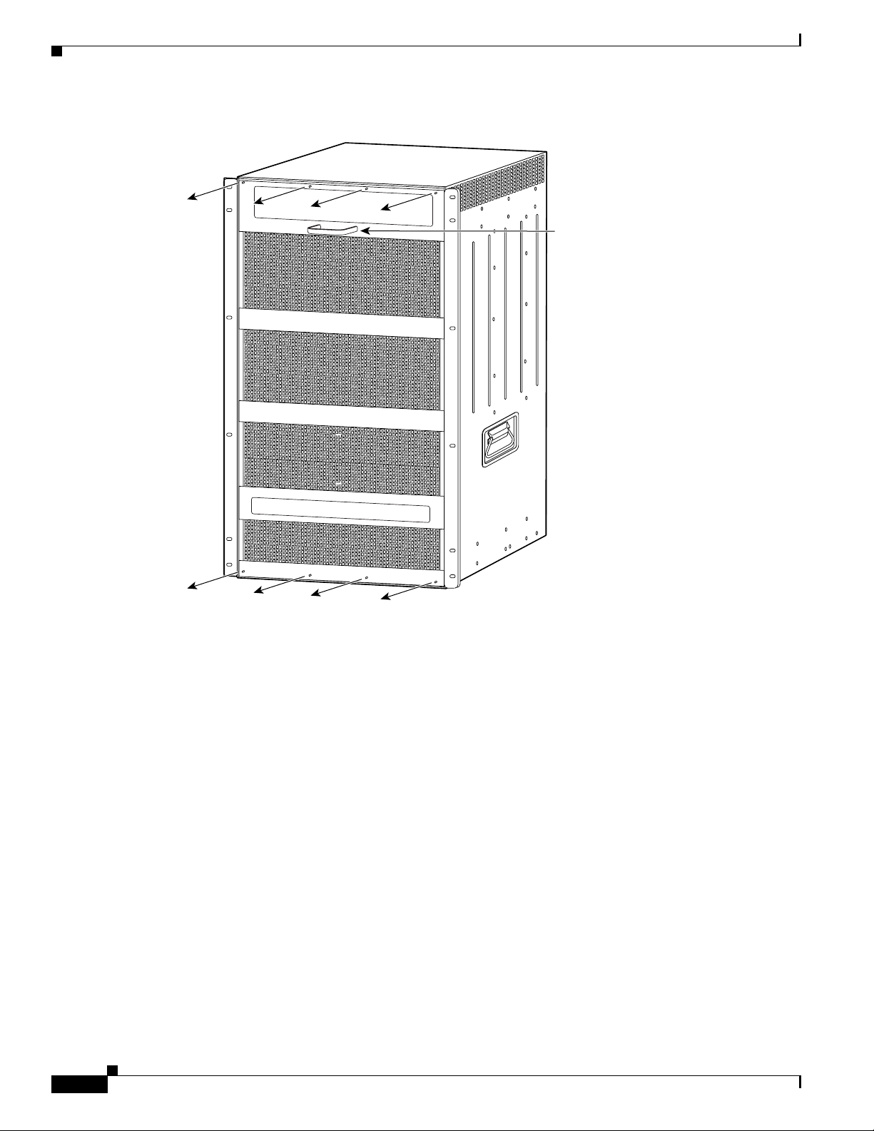
Step 1 Use a number 1 Phillips-head screwdriver to remov e the 8 panel scre ws, 4 each located along the top and
Step 2 Grasp the panel handle and pull the panel away from the chassis.
78-16162-02
Hazardous voltage or energy is present on the backplane when the system is operating. Use caution
when servicing.
Statement 1034
To remove the panel safety cover, perform these steps:
bottom of the chassis. (See Figure 1.) Set the screws aside.
Catalyst 6509-NEB Switch and Cisco OSR-7609 Router Upgrade Note
5
Page 6
Replacing the Panel Safety Cover
l
le
Figure 1 Removing the Panel Safety Cover
Pane
hand
105072
Step 3 On the new panel safety cover, grasp the panel handle and press the panel into place, starting at the
bottom of the chassis and working up. Be careful not to damage the EMI gasket.
Step 4 Use a number 1 Phillips-head screwdriver to install th e 8 panel screws, 4 each located along the top and
bottom of the chassis. (See Figure 2.)
Step 5 Proceed to the “Re placing the Fan Tray” section on page 7 to replace the fan tray.
Catalyst 6509-NEB Switch and Cisco OSR-7609 Router Upgrade Note
6
78-16162-02
Page 7
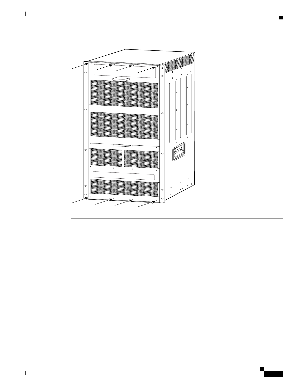
Figure 2 Installing the Panel Safety Cover
105071
Replacing the Fan Tray
Replacing the Fan Tray
This section describes how to remove and install the fan tray for the Catalyst 6509-NEB switch and
Cisco OSR-7609 Router . A flat-blade or number 2 Phillips-head screwdriver is required to perform this
procedure.
78-16162-02
Catalyst 6509-NEB Switch and Cisco OSR-7609 Router Upgrade Note
7
Page 8
Replacing the Fan Tray
C
Captive installation
Removing the Fan Tray
Warning
When removing the fan tray, keep your hands and fingers away from the spinning fan blades. Let the
fan blades completely stop before you remove the fan tray.
Statement 258
To remove the existing fan tray, follow these steps:
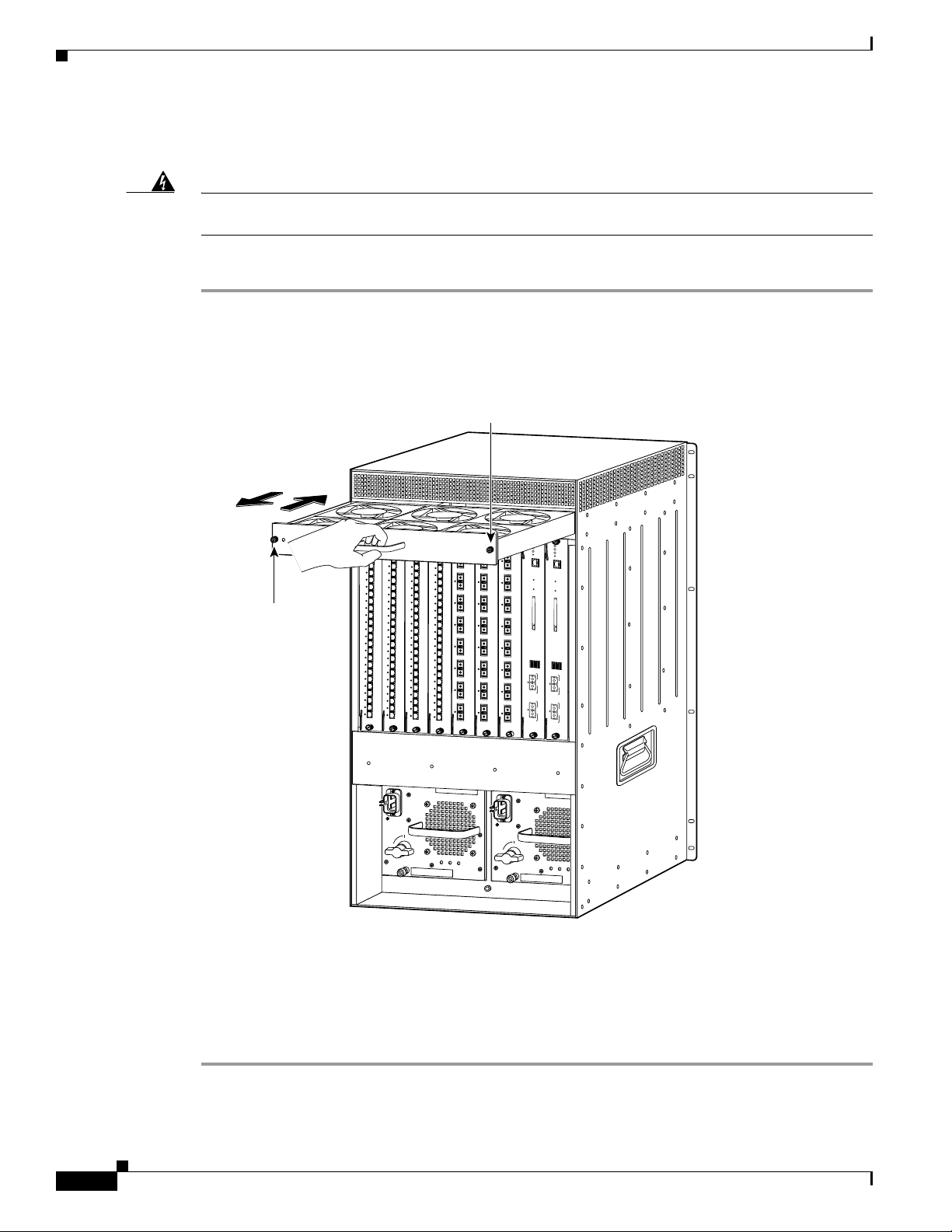
Step 1 Use a flat-blade or number 2 Phillips-head screwdriver to loosen the two captive installation screws on
the fan tray by turning them counterclockwise. (See Figure 3.)
Figure 3 Removing the Fan Tray
screw
SUPERVISOR2
FAN
STATUS
aptive installation
screw
24 PORT 100FX
WS-X6224
24 PORT 100FX
WS-X6224
24 PORT 100FX
8 PORT GIGABIT ETHERNET
WS-X6224
WS-X6408
8 PORT GIGABIT ETHERNET
STATUS
STATUS
1
LINK
LINK
2
LINK
LINK
3
LINK
LINK
4
LINK
LINK
5
LINK
LINK
6
LINK
LINK
7
LINK
LINK
8
LINK
LINK
9
LINK
LINK
10
LINK
LINK
11
LINK
LINK
12
LINK
LINK
13
LINK
LINK
14
LINK
LINK
15
LINK
LINK
16
LINK
LINK
17
LINK
LINK
18
LINK
LINK
19
LINK
LINK
20
LINK
LINK
21
LINK
LINK
22
LINK
LINK
23
LINK
LINK
24
LINK
LINK
STATUS
1
1
1
LINK
LINK
2
2
2
LINK
LINK
3
3
3
LINK
LINK
4
4
4
LINK
LINK
5
5
5
LINK
LINK
6
6
6
LINK
LINK
7
7
7
LINK
LINK
8
8
8
LINK
LINK
9
9
9
LINK
LINK
10
10
10
LINK
LINK
11
11
11
LINK
LINK
12
12
12
LINK
LINK
13
13
13
LINK
LINK
14
14
14
LINK
LINK
15
15
15
LINK
LINK
16
16
16
LINK
LINK
17
17
17
LINK
LINK
18
18
18
LINK
LINK
19
19
19
LINK
LINK
20
20
20
LINK
LINK
21
21
21
LINK
LINK
22
22
22
LINK
LINK
23
23
23
LINK
LINK
24
24
24
LINK
LINK
WS-X6408
STATUS
STATUS
1
1
LINK
LINK
2
2
LINK
LINK
3
3
LINK
LINK
4
4
LINK
LINK
5
5
LINK
LINK
6
6
LINK
LINK
7
7
LINK
LINK
8
8
LINK
LINK
8 PORT GIGABIT ETHERNET
STATUS
LINK
LINK
LINK
LINK
LINK
LINK
LINK
LINK
WS-X6K-SUP2-2GE
SUPERVISOR2
WS-X6K-SUP2-2GE
WS-X6408
STATUS
STATUS
SYSTEM
SYSTEM
CONSOLE
CONSOLE
PWR MGMT
PWR MGMT
RESET
RESET
CONSOLE
CONSOLE
1
CONSOLE
CONSOLE
MODE
PORT
MODE
PORT
2
3
PCMCIA
PCMCIA
EJECT
EJECT
4
5
100%
1%
100%
1%
Switch Load
6
7
8
Switch Load
PORT 1
PORT 1
LINK
LINK
PORT 2
PORT 2
LINK
LINK
o
INPUT
FAN
OUTPUT
OK
OK
o
FAIL
INPUT
FAN
OUTPUT
OK
OK
FAIL
30696
Step 2
Grasp the fan tray handle with one hand and pull the fan tray outward about 1 inch; rock it gently, if
necessary, to unseat the power co nnector from the backplane. Wait for the fans to stop spinning.
Step 3 Once the fans have stopped spinning, pull the fan tray out further and support the underside of the fan
tray with the other hand.
Step 4 Pull the fan tray clear of the chassis, and put it in a safe place.
Catalyst 6509-NEB Switch and Cisco OSR-7609 Router Upgrade Note
8
78-16162-02
Page 9
Installing the High Speed Fan Tray
C
Captive installation
To install the high speed fan tray, follow these steps:
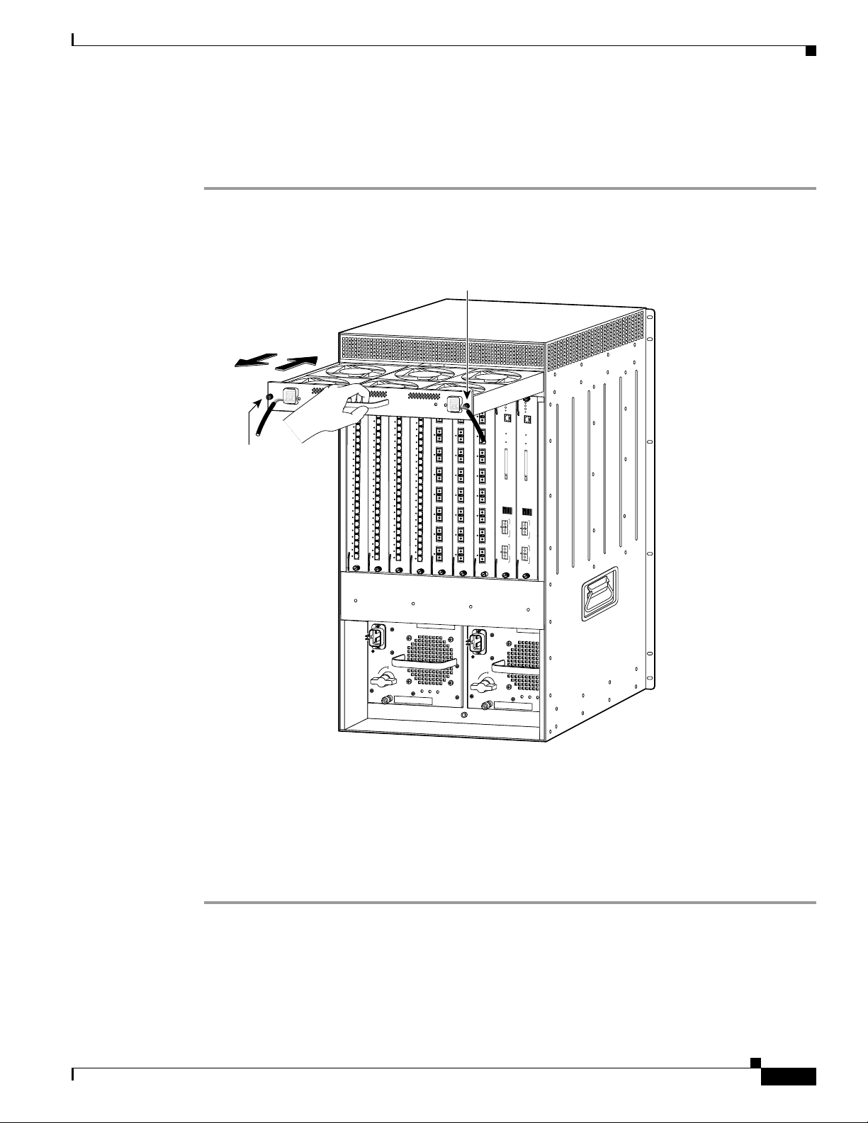
Step 1 Hold the fan tray with the fans facing down and the FAN FAIL LED on the right. (See Figure 4.)
Figure 4 Installing the High Speed Fan Tray
Replacing the Fan Tray
screw
48V INPUT 1
RTN -48VDC GND
WS-C6500-NEB-FAN2
aptive installation
screw
HIGH SPEED FAN
24 PORT 100FX
WS-X6224
24 PORT 100FX
INPOUT POWER
GOOD
1
LINK
2
LINK
3
LINK
4
LINK
5
LINK
6
LINK
7
LINK
8
LINK
9
LINK
10
LINK
11
LINK
12
LINK
13
LINK
14
LINK
15
LINK
16
LINK
17
LINK
18
LINK
19
LINK
20
LINK
21
LINK
22
LINK
23
LINK
24
LINK
WS-X6224
STATUS
STATUS
1
1
LINK
LINK
2
2
LINK
LINK
3
3
LINK
LINK
4
4
LINK
LINK
5
5
LINK
LINK
6
6
LINK
LINK
7
7
LINK
LINK
8
8
LINK
LINK
9
9
LINK
LINK
10
10
LINK
LINK
11
11
LINK
LINK
12
12
LINK
LINK
13
13
LINK
LINK
14
14
LINK
LINK
15
15
LINK
LINK
16
16
LINK
LINK
17
17
LINK
LINK
18
18
LINK
LINK
19
19
LINK
LINK
20
20
LINK
LINK
21
21
LINK
LINK
22
22
LINK
LINK
23
23
LINK
LINK
24
24
LINK
LINK
48V INPUT 2
24 PORT 100FX
8 PORT GIGABIT ETHERNET
WS-X6224
WS-X6408
8 PORT GIGABIT ETHERNET
STATUS
STATUS
FAN FAIL
INPOUT POWER
1
LINK
GOOD
RTN -48VDC GND
1
LINK
2
LINK
LINK
3
LINK
4
LINK
2
5
LINK
LINK
LINK
6
LINK
7
LINK
3
8
LINK
LINK
LINK
9
LINK
10
LINK
11
4
LINK
LINK
LINK
12
LINK
13
LINK
14
5
LINK
LINK
LINK
15
LINK
16
LINK
17
6
LINK
LINK
LINK
18
LINK
19
LINK
20
LINK
7
LINK
LINK
21
LINK
22
LINK
23
LINK
8
LINK
LINK
24
LINK
SUPERVISOR2
WS-X6K-SUP2-2GE
SUPERVISOR2
WS-X6408
8 PORT GIGABIT ETHERNET
STATUS
STATUS
1
1
LINK
2
2
LINK
3
3
LINK
4
4
LINK
5
5
LINK
6
6
LINK
7
7
LINK
8
8
LINK
WS-X6K-SUP2-2GE
WS-X6408
STATUS
STATUS
SYSTEM
SYSTEM
CONSOLE
CONSOLE
PWR MGMT
PWR MGMT
RESET
RESET
CONSOLE
CONSOLE
CONSOLE
CONSOLE
MODE
PORT
MODE
PORT
PCMCIA
PCMCIA
EJECT
EJECT
100%
1%
100%
1%
Switch Load
Switch Load
PORT 1
PORT 1
LINK
LINK
PORT 2
PORT 2
LINK
LINK
Step 2
o
INPUT
FAN
OUTPUT
OK
OK
Place the fan tray into the front chassis cavity so that it rests on the chassis, and then lift the fan tray up
o
FAIL
INPUT
FAN
OUTPUT
OK
OK
FAIL
105068
slightly, aligning the top and bottom chassis guides.
Step 3 Push the fan tray into the chassis until the power connector seats in the backplane and the captive
Step 4 Use a flat-blade or number 2 Phillips-head screwdriver to tighten the captive inst allation sc rews.
Step 5 Proceed to the “Replacing the Power Supply” section on page 10 to replace the power supply.
installation screws make contact with the chassis.
78-16162-02
Catalyst 6509-NEB Switch and Cisco OSR-7609 Router Upgrade Note
9
Page 10

Replacing the Power Supply
r
16029
Replacing the Power Supply
Note DC-input systems—See the “Connecting Site Power to the Fan Tray for DC-Input Systems” section on
page 15 to connect site power to the high speed fan tray.
This section describes how to remove and install AC-input power supplies for the Catalyst 6509-NEB
switch and Cisco OSR-7609 router.
Removing an AC-Input Power Supply
Warning
Hazardous voltage or energy is present on the backplane when the system is operating. Use caution
when servicing.
Statement 1034
To remove an AC-input power supply, follow these steps:
Step 1 Loosen the captive installation screw. (See Figure 5.)
Caution Use both hands to in stall and rem ov e po wer sup plies. Each Catal yst 6500 series AC-input power supply
weighs between 22 pounds (9.9 kg) and 28 pounds (12.6 kg).
Step 2 Grasp the power supply handle with one hand, and slide the power supply part of the way out of the
chassis. Place your other hand underneath the power supply, as shown in Figure 6, and slide the power
supply completely out of the chassis.
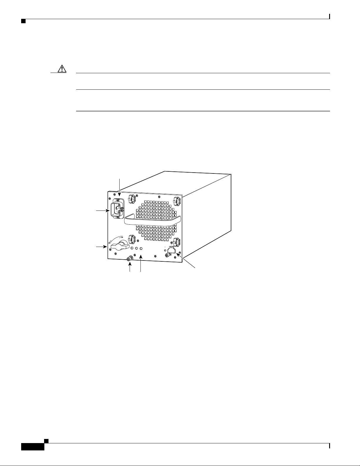
Figure 5 AC-Input Power Supply Front Panel
AC power
connection
Cable
etention
device
I
Power
switch
Catalyst 6509-NEB Switch and Cisco OSR-7609 Router Upgrade Note
10
0
Captive installation
screw
INPUT
FAN
OUTPUT
OK
OK
FAIL
Status LEDs
78-16162-02
Page 11

Figure 6 Removing an AC-Input Power Supply
48V INPUT 1
FAN
STATUS
RTN -48VDC GND
WS-C6500-NEB-FAN2
8 PORT OC3 POS MM
STATUS
2
1
LINK
1
2
LINK
4
3
LINK
3
4
LINK
CARRIER
LINK
ALARM
RESET
1
2
3
4
5
6
7
8
OSM-8OC3-POS MM
INPOUT POWER
GOOD
8 PORT OC3 POS MM
OSM-8OC3-POS MM
OC12 POS MM
STATUS
2
1
LINK
LINK
1
1
2
LINK
LINK
2
4
3
LINK
LINK
3
3
4
LINK
LINK
4
CARRIER
LINK
ALARM
RESET
1
2
3
4
5
6
7
ALARM
8
PORT 3
CARRIER
ALARM
HIGH SPEED FAN
OSM-40C12-POS-MM
WS-C6500-SFM
OC12 POS MM
WS-C6500-SFM
SWITCH FABRIC MDL
STATUS
2
1
STATUS
ACTIVE
4
3
RESET
CARRIER
ALARM
ACTIVE
RX
TX
RX
PORT 1
TX
CARRIER
ALARM
ACTIVE
RX
TX
RX
PORT 2
TX
CARRIER
ACTIVE
SELECT
NEXT
RX
TX
RX
TX
ACTIVE
RX
TX
RX
TX
SWITCH FABRIC MDL
OSM-40C12-POS-MM
OC12 POS MM
STATUS
STATUS
2
1
ACTIVE
LINK
LINK
1
1
LINK
LINK
2
2
4
3
LINK
LINK
3
3
LINK
LINK
4
4
RESET
CARRIER
ALARM
ACTIVE
RX
TX
RX
PORT 1
TX
CARRIER
ALARM
ACTIVE
RX
TX
RX
PORT 2
TX
CARRIER
ALARM
ALARM
SELECT
NEXT
ACTIVE
RX
TX
RX
PORT 3
PORT 3
TX
CARRIER
ALARM
ALARM
ACTIVE
RX
TX
RX
TX
48V INPUT 2
FAN FAIL
INPOUT POWER
GOOD
RTN -48VDC GND
OSM-40C12-POS-MM
SUPERVISOR2
WS-X6K-SUP2-2GE
SUPERVISOR2
STATUS
2
1
4
3
RESET
CARRIER
ALARM
ACTIVE
RX
TX
RX
PORT 1
TX
CARRIER
ALARM
ACTIVE
RX
TX
RX
PORT 2
TX
CARRIER
ACTIVE
RX
TX
RX
TX
CARRIER
ACTIVE
RX
TX
RX
TX
WS-X6K-SUP2-2GE
STATUS
STATUS
SYSTEM
SYSTEM
CONSOLE
CONSOLE
PWR MGMT
PWR MGMT
RESET
RESET
CONSOLE
CONSOLE
CONSOLE
CONSOLE
MODE
PORT
MODE
PORT
LINK
PCMCIA
PCMCIA
EJECT
EJECT
100%
1%
100%
1%
Switch Load
Switch Load
PORT 1
PORT 1
LINK
LINK
PORT 2
PORT 2
LINK
Replacing the Power Supply
105074
I
0
INPUT
FAN
OUTPUT
OK
OK
FAIL
78-16162-02
Catalyst 6509-NEB Switch and Cisco OSR-7609 Router Upgrade Note
11
Page 12
Replacing the Power Supply
AC power
r
Installing the 3000 W AC-Input Power Supply
Caution Use both hands to in stall and rem ov e po wer sup plies. Each Catal yst 6500 series AC-input power supply
weighs between 22 pounds (9.9 kg) and 28 pounds (12.6 kg).
To install the 3000 W AC-input power supply, follow these steps:
Step 1 Ensure that the system (earth) ground connection has been made. For ground connection instructions,
refer to the installation guide for your hardware platform.
Step 2 Verify that the power switch is in the Off (0) position on the power supply you are installing.
(See Figure 7.)
Figure 7 3000 Watt AC-Input Power Supply Front Panel
connection
Step 3
Cable
tention
device
Power
switch
N
I
O
110-120V - 15A
200-240V - 15A
60/50HZ
L
L
A
T
S
N
U
R
I
OUTPUT 42V /17A
42V /17A
INPUT
FAN
OUTPUT
OK
OK
FAIL
OK
+
105069
External power
Captive installation
Status LEDs (3)
connector cove
screw
Grasp the power supply handle with one hand. Place your other hand underneath the power supply, as
shown in Figure 8. Slide the power supply into the power supply bay. Make sure that the power supply
is fully seated in the bay.
12
Catalyst 6509-NEB Switch and Cisco OSR-7609 Router Upgrade Note
78-16162-02
Page 13
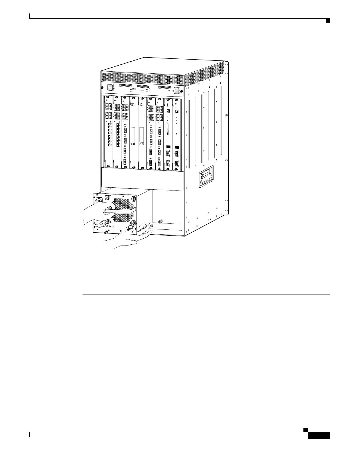
Figure 8 Installing the 3000 W Power Supply
48V INPUT 1
FAN
STATUS
RTN -48VDC GND
WS-C6500-NEB-FAN2
8 PORT OC3 POS MM
STATUS
2
1
LINK
1
2
LINK
4
3
LINK
3
4
LINK
CARRIER
ALARM
RESET
1
2
3
4
5
6
7
8
INPOUT POWER
GOOD
OSM-8OC3-POS MM
8 PORT OC3 POS MM
OSM-8OC3-POS MM
OC12 POS MM
STATUS
2
1
LINK
LINK
1
1
2
LINK
LINK
2
4
3
LINK
LINK
3
3
4
LINK
LINK
4
LINK
CARRIER
LINK
ALARM
RESET
ALARM
1
2
PORT 1
3
ALARM
4
5
6
PORT 2
7
CARRIER
ALARM
8
PORT 3
CARRIER
ALARM
HIGH SPEED FAN
OSM-40C12-POS-MM
WS-C6500-SFM
OC12 POS MM
WS-C6500-SFM
SWITCH FABRIC MDL
STATUS
2
1
STATUS
ACTIVE
4
3
RESET
CARRIER
ACTIVE
RX
TX
RX
TX
CARRIER
ACTIVE
RX
TX
RX
TX
ACTIVE
SELECT
NEXT
RX
TX
RX
TX
ACTIVE
RX
TX
RX
TX
SWITCH FABRIC MDL
NEXT
OSM-40C12-POS-MM
OC12 POS MM
STATUS
STATUS
2
1
ACTIVE
LINK
LINK
1
1
LINK
LINK
2
2
4
3
LINK
LINK
3
3
LINK
LINK
4
4
RESET
CARRIER
ALARM
ALARM
ACTIVE
RX
TX
RX
PORT 1
PORT 1
TX
CARRIER
ALARM
ALARM
ACTIVE
RX
TX
RX
PORT 2
PORT 2
TX
CARRIER
CARRIER
ALARM
ALARM
SELECT
ACTIVE
RX
TX
RX
PORT 3
PORT 3
TX
CARRIER
CARRIER
ALARM
ALARM
ACTIVE
RX
TX
RX
TX
48V INPUT 2
FAN FAIL
INPOUT POWER
GOOD
RTN -48VDC GND
OSM-40C12-POS-MM
SUPERVISOR2
WS-X6K-SUP2-2GE
SUPERVISOR2
STATUS
2
1
4
3
RESET
CARRIER
ACTIVE
RX
TX
RX
TX
CARRIER
ACTIVE
RX
TX
RX
TX
ACTIVE
RX
TX
RX
TX
ACTIVE
RX
TX
RX
TX
WS-X6K-SUP2-2GE
STATUS
STATUS
SYSTEM
SYSTEM
CONSOLE
CONSOLE
PWR MGMT
PWR MGMT
RESET
RESET
CONSOLE
CONSOLE
CONSOLE
CONSOLE
MODE
PORT
MODE
PORT
LINK
PCMCIA
PCMCIA
EJECT
EJECT
100%
1%
100%
1%
Switch Load
Switch Load
PORT 1
PORT 1
LINK
LINK
PORT 2
PORT 2
LINK
Connecting Power to the Fan Tray
110-120V - 15A
200-240V - 15A
60/50HZ
L
I
L
A
T
S
N
N
U
I
Step 4
R
O
INPUT
FAN
OUTPUT
OK
OK
FAIL
Tighten the power supply captive installation screw. (See Figure 7.)
OUTPUT 42V
42V
OK
m
/
m
+
Step 5 If you have a redundant power supply, install it now following the steps in this section.
Step 6 Proceed to the “Connecting Power to the Fan Tray” section on page 13 to connect power to the high
speed fan tray.
Connecting Power to the Fan Tray
The high-speed fan tray requires external power, either from the 3000 W AC-input power supply or
from an external DC power source. The fan tray ships with power wires secured at each terminal block.
If you are using the 3000 W AC-input power supply, use the supplied cables to connect the fan tray wires
to the power supply.
If you are using a DC-input power supply, remove the wires from the fan tray and connect directly to a
DC power source.
105070
78-16162-02
The following sections describe how to connect power to the fan tray:
• Installing the Fan Tray Power Cable for AC-Input Systems, page 14
• Connecting Site Power to the Fan Tray for DC-Input Systems, page 15
Catalyst 6509-NEB Switch and Cisco OSR-7609 Router Upgrade Note
13
Page 14

Connecting Power to the Fan Tray
1
Installing the Fan Tray Power Cable for AC-Input Systems
Note The fan tray ships with power wires secured at each terminal block. Use these wires to connect the fan
tray to the 3000 W AC-input power supply using the supplied cables. If you have redundant power
supplies, repeat the steps in this section for the redundant power supply.
To connect the high speed fan tray to the 3000 W AC-input power supply, follow these steps:
Step 1 Connect the female end of the supplied power cable (see Figu re 9 ) to the fan tray wire connector. Press
the two ends together until you hear a click.
Figure 9 Cable Connectors
To fan cable To power supply
Step 2
On the power supply , loosen the thumb screw on the e xternal power connector cover and lift up the cov er .
(See Figure 10.)
Figure 10 External Power Connector Cover
1 2
OUTPUT 42V /17A
42V /17A
OK
OUTPUT 42V /17A
42V /17A
OK
+
05083
Step 3
Connect the male end of the supplied power cable to the female end of the external power connector on
the power supply until you hear a click.
Step 4 If you have redundant power supplies, repeat the steps in this section fo r the redundant power supply.
14
Catalyst 6509-NEB Switch and Cisco OSR-7609 Router Upgrade Note
78-16162-02
Page 15

Connecting Site Power to the Fan Tray for DC-Input Systems
Terminal block covers
1
Note To provide redundancy, you may choose to connect each fan terminal block to a separate power source.
Note Each input of the fan tray is rated 10 A @ -40 to -60 VDC.
Connecting Power to the Fan Tray
Warning
This product requires short-circuit (overcurrent) protection, to be provided as part of the building
installation. Install only in accordance with national and local wiring regulations.
Warning
Before performing any of the following procedures, ensure that powe r is removed from t he DC circuit.
Statement 1003
To connect the high speed fan tray to an external DC power source, follow these steps:
Step 1 Locate the terminal block c overs on the fan tray. (See Figure 11.)
Figure 11 Terminal Block Covers on Fan Tray
48V INPUT 1
RTN -48VDC GND
WS-C6500-NEB-FAN2
INPUT POWER
GOOD
HIGH SPEED FAN
FAN FAIL
INPUT POWER
GOOD
RTN -48VDC GND
48V INPUT 2
Statement 1045
05081
Step 2
78-16162-02
The terminal block cover is held in place by two clips inserted into the fan tray front panel. Press the
bottom of the terminal block cover, lift the cover up, and remove the cover. (See Figure 12.)
Catalyst 6509-NEB Switch and Cisco OSR-7609 Router Upgrade Note
15
Page 16

Connecting Power to the Fan Tray
k
48V INPU
105084
Figure 12 Removing the Terminal Block Cover
Terminal bloc
cover
Step 3
Step 4
With a flat blade screwdriver, disconnect the input wires from the terminal block. (See Figure 13.)
Figure 13 Input Wire Connections on the Terminal Block
+
RTN -48vdc GND
T 1
GND
INPUT POWER
GOOD
Connect the DC-input wires to the terminal block (see Figure 14) in this order:
• Ground
16
• Negative (-)
• Positive (+)
Catalyst 6509-NEB Switch and Cisco OSR-7609 Router Upgrade Note
78-16162-02
Page 17

Figure 14 DC-Input Wire Connections on the Terminal Block
105085
48V INP
UT 1
+
GND
INPUT POWER
GOOD
RTN -48vdc GND
Replacing the Supervisor Engine
Warning
Step 5 After ensuring that all wire connections are secure, re install the term inal bloc k cover.
When installing or replacing the unit, the ground connection must always be made first and
disconnected last.
Statement 1046
Replacing the Supervisor Engine
Before you can power up the system, you need to remove the supervisor engine from slot 1 (if a
redundant supervisor engine is present, remove it from slot 2) and install the Supervisor Engine 720 or
the Supervisor Engine 32 in slot 5 or 6.
Removing the Supervisor Engine
This section describes how to remove an existing supervisor engine from a chassis slot.
To remove a supervisor engine from the chassis, perform these steps:
Step 1 Disconnect any network interface cables attached to the supervisor engine.
Step 2 Verify that the captive installation screws on all of the modules in the chassis are tight. This step assures
that the space created by the removed supervisor engine is maintained.
78-16162-02
Note If the captive installation screws are loose, the electromagnetic interference (EMI) gaskets on
the installed modules will push the modules toward the open slot, reducing the opening size an d
making it difficult to install the replacement module.
Catalyst 6509-NEB Switch and Cisco OSR-7609 Router Upgrade Note
17
Page 18

Replacing the Supervisor Engine
Step 3 Loosen the two captive installation screws on the supervisor en gine.
Step 4 Place your thumbs on the ejector levers located at the top and bottom of the supervisor engine, and
simultaneously rotate the levers outward to unseat the supervisor engine from the backplane connector.
Step 5 Grasp the edges of the supervisor engine, and slide the supervisor engine straight out of the slot. D o not
touch the module circuitry.
Step 6 Place the supervisor engine on an antistatic mat or antistatic foam.
Step 7 If the slot is to remain empty, install a modul e filler plate to keep dust out of the chassis and to maintain
proper airflow through the chassis.
Installing the Supervisor Engine
This section describes how to install the Supervisor Engine 720 or the Supervisor Engine 32 in the
Catalyst 6509-NEB switch and the Cisco OSR-7609 Router.
Caution To prevent ESD damage, handle modules by the carrier edges only.
Note The Supervisor Engine 720 or Supervisor Engine 32 must be installed in slot 5 or 6 of the Catalyst
6509NEB or Cisco OSR7609 chassis.
To install the supervisor engine in the chassis, perform these steps:
Step 1 Choose a slot for the supervisor engine.
Step 2 Verify that there is enough clearance to accommodate any interface equipment that you will connect
directly to the supervisor engine ports. If possible, place modules between empty slots that contain only
module filler plates.
Step 3 Verify that the captive installation screws are tightened on all modules installed in the chassis. This
assures that the EMI gaskets on all modules are fully compressed in order to maximize the opening space
for the new module or the replacement module.
Note If the captive installation screws are loose, the EMI gaskets on the installed modules will push
adjacent modules toward the open slot, reducing the opening size and making it difficult to
install the replacement module.
Step 4 Remove the module filler plate by removing the two Phillips pan-head screws from the filler plate. To
remove a module, see the “Removing the Supervisor Engine” section on page 17.
Step 5 Fully open both ejector levers on the supervisor engine. (See Figure 15.)
Step 6 Position the supervisor engine in the slot. (See Figure 15.) Make sure that you align the sides of the
module carrier with the slot guides on the top and bottom of the slot.
Step 7 Carefully slide the supervisor engine into the slot until the EMI gasket along the right edge of the
supervisor engine makes contact with the module in the slot adjacent to it and both ejector levers have
closed to approximately 45 degrees with respect to the supervisor engine faceplate. (See Figure 16.)
18
Catalyst 6509-NEB Switch and Cisco OSR-7609 Router Upgrade Note
78-16162-02
Page 19

Replacing the Supervisor Engine
4
3
6
Step 8 Using the t hum b and forefinger of ea ch ha nd, g ras p th e two ejector levers and exert a slight pressure to
the left, deflecting the module approximately 0.040 inches (1 mm) to create a small gap between the
supervisor engine's EMI gasket and the module adjacent to it. (See Figure 16.)
Caution Do not exert too much pressure on the ejector levers. They will bend and be damaged.
Step 9 While pressing on the ejector levers, simultaneously close them to fully seat th e supervisor engine in the
backplane connector. The ejector levers are fully closed when they are flush with the supervisor engine
faceplate. (See Figure 17.)
Step 10 Tighten the two captive installation screws on the supervisor engine.
Note Make sure the ejector levers are fully closed before tightenin g the capt ive installation screws.
Figure 15 Positioning the Supervisor Engine in the Chassis
Ejector lever fully
extended
48V INPUT 1
RTN -48VDC GND
WS-C6500-NEB-FAN2
INPOUT POWER
GOOD
24 PORT 100FX
WS-X6224
HIGH SPEED FAN
48V INPUT 2
FAN FAIL
INPOUT POWER
GOOD
RTN -48VDC GND
EMI
gasket
EMI
gasket
110-120V - 15A
200-240V - 15A
60/50HZ
L
I
L
A
T
S
N
N
I
U
R
O
INPUT
FAN
OUTPUT
OK
OK
FAIL
110-120V - 15A
200-240V - 15A
60/50HZ
L
I
L
A
T
S
N
N
I
U
m
OUTPUT 42V
/
R
m
42V
OK
O
+
m
OUTPUT 42V
/
m
42V
OK
INPUT
FAN
OUTPUT
OK
OK
FAIL
+
105092
Insert module
between slot guides
78-16162-02
Catalyst 6509-NEB Switch and Cisco OSR-7609 Router Upgrade Note
19
Page 20

Replacing the Supervisor Engine
le
P
P
SWITCH FABIRD MDL
WS-C6500-SFM
STATUS
ACTIVE
Figure 16 Clearing the EMI Gasket in the Chassis
Gap between the modu
EMI gasket and the
module above it
1 mm
ress left
ress left
RTN -48VDC GND
WS-C6500-NEB-FAN2
48V INPUT 1
INPOUT POWER
GOOD
110-120V - 15A
200-240V - 15A
60/50HZ
A
T
S
N
I
O
HIGH SPEED FAN
24 PORT 100FX
WS-X6224
24 PORT 100FX
L
I
L
N
U
R
m
OUTPUT 42V
/
m
42V
OK
INPUT
FAN
OUTPUT
OK
OK
FAIL
+
48V INPUT 2
FAN FAIL
INPOUT POWER
GOOD
RTN -48VDC GND
110-120V - 15A
200-240V - 15A
60/50HZ
L
I
L
A
T
S
N
N
I
U
R
O
m
OUTPUT 42V
/
m
42V
OK
INPUT
FAN
OUTPUT
OK
OK
FAIL
+
105093
20
Catalyst 6509-NEB Switch and Cisco OSR-7609 Router Upgrade Note
78-16162-02
Page 21

Figure 17 Ejector Lever Closure in the Chassis
105094
Powering Up the System
48V INPUT 1
RTN -48VDC GND
WS-C6500-NEB-FAN2
INPOUT POWER
GOOD
All ejector levers flush
with module faceplate
HIGH SPEED FAN
48V INPUT 2
FAN FAIL
INPOUT POWER
GOOD
RTN -48VDC GND
Powering Up the System
This section describes how to power up the system.
• AC-Input Systems, page 21
• DC-Input Systems, page 22
AC-Input Systems
To power up your AC-input system, follow these steps:
Step 1 Plug the power cord into the power supply, and tighten the screw on the cable retention device.
Step 2 Connect the other end of the power cord to an AC-input power source.
Caution In a system with dual power supplies, connect each power supply to a separate input source. In case of
a power source failure, the second source will most likely still be available.
Step 3 Turn the power switch to the On (|) position on the po wer su pply. Switching the power switch to On also
engages a pawl that locks the power supply in the bay.
78-16162-02
Catalyst 6509-NEB Switch and Cisco OSR-7609 Router Upgrade Note
21
Page 22

Verifying Installation
DC-Input Systems
To power up your DC-input system, follow these steps:
Step 1 Remove the tape from the circuit breaker switch handle, and restore po wer by moving th e circuit break er
switch handle to the On (|) position.
Step 2 Turn the power switch to the On (|) position on the power supply. Turning the power switch on also
engages a pawl that locks the power supply in the chassis.
Verifying Installation
After you have powered up the switch, verify the operation of the newly installed hardware as follows:
Step 1 Verify power supply operation by checking that the power supply front panel LEDs are in these states:
• INPUT OK LED is green
• FAN OK LED is green
• OUTPUT FAIL LED is not lit
• 42V LED is green
If the LEDs indicate a power problem, refer to the installation guide for your hardware platform for
troubleshooting information.
Step 2 Verify the high speed fan tray operation by checking that the fan tray LEDs are in these:
• INPUT POWER GOOD LED is green (there is one LED for each power input; if both inputs are
used, verify both LEDs)
• FAN FAIL LED is green
If the LEDs indicate a problem, refer to the installation guide for your hardware platform for
troubleshooting information.
Step 3 Verify that the supervisor engine STATUS LED is lit. Check the STATUS LED periodically. If the
STATU S LED changes from orange to green, the supervisor engine has successf ully completed the boot
process and is now online. If the STATUS LED remains orange or turns red, the supervisor engine has
not successfully completed the boot process and may have encountered an error.
22
Catalyst 6509-NEB Switch and Cisco OSR-7609 Router Upgrade Note
78-16162-02
Page 23

Related Documentation
For additional information on Catalyst 6500 series switches and command-line interface (CLI)
commands, refer to the following publications:
• Regulatory Compliance and Safety Information for the Catalyst 6500 Series Switches
• Regulatory Compliance and Safety Info rmation for the Cisco 7600 Series Routers
• Catalyst 6500 Series Switch Installation Guide
• Cisco 7609 Router Installation Guide
Obtaining Documentation
Cisco documentation and additional literature are available on Cisco.com. Cisco also provides several
ways to obtain technical assistance and other technic al resources. These sections explain how to obtain
technical information from Cisco Systems.
Cisco.com
Related Documentation
You can access the most current Cisco documentation at this URL:
http://www.cisco.com/techsupport
You can access the Cisco website at this URL:
http://www.cisco.com
You can access international Cisco websites at this URL:
http://www.cisco.com/public/countries_languages.shtml
Product Documentation DVD
The Product Documentation DVD is a comprehensive library of technical product documentation on a
portable medium. The DVD enables you to access multiple versions of installation, configuration, and
command guides for Cisco hardware and software products. W it h the D VD, you h av e access to the same
HTML documentation that is found on the Cisco website without being connected to the Internet.
Certain products also have .PDF versions of the documentation available.
The Product Documentation DVD is a vailable as a single unit or as a subscription. Regist ered Cisco.c om
users (Cisco direct customers) can order a Product D ocument ation DVD (product number
DOC-DOCDVD= or DOC-DOCDVD=SUB) from Cisco Marketplace at this URL:
http://www.cisco.com/go/marketplace/
78-16162-02
Catalyst 6509-NEB Switch and Cisco OSR-7609 Router Upgrade Note
23
Page 24

Documentation Feedback
Ordering Documentation
Registered Cisco.com users may order Cisco documentation at the Product Documentation Store in the
Cisco Marketplace at this URL:
http://www.cisco.com/go/marketplace/
Nonregistered Cisco.com users can order tec hnical docu mentatio n from 8:00 a.m . to 5:00 p.m .
(0800 to 1700) PDT by calling 1 866 463-3487 in the United States and Canada, or elsewhere by
calling 011 408 519-5055. You can also order documentation by e-mail at
tech-doc-store-mkpl@external.cisco.com or by fax at 1 408 519-5001 in the United States and Canada,
or elsewhere at 011 408 519-5001.
Documentation Feedback
You can rate and provide feedback about Cisco technical documents by completing the online feedback
form that appears with the technical documents on Cisco.com.
You can submit comments about Cisco documentation by using the response card (if present) behind the
front cover of your document or by writing to the following address:
Cisco Systems
Attn: Customer Document Ordering
170 West Tasman Drive
San Jose, CA 95134-9883
We appreciate your comments.
Cisco Product Security Overview
Cisco provides a free online Security Vulnerability Policy portal at this URL:
http://www.cisco.com/en/US/products/products_security_vulnerability_policy.html
From this site, you will find information about how to:
• Report security vulnerabilities in Cisco products.
• Obtain assistance with security incidents that involve Cisco products.
• Register to receive security information from Cisco.
A current list of security advisories, security notices, and security responses for Cisco products is
available at this URL:
http://www.cisco.com/go/psirt
To see security advisories, security notices, and security responses as they are updated in real time, you
can subscribe to the Product Security Incident Response T eam Really Simple Syndi cation (PSIRT RSS)
feed. Information about how to subscribe to the PSIRT RSS feed is found at this URL:
http://www.cisco.com/en/US/products/products_psirt_rss_feed.html
24
Catalyst 6509-NEB Switch and Cisco OSR-7609 Router Upgrade Note
78-16162-02
Page 25

Reporting Security Problems in Cisco Products
Cisco is committed to delivering secure products. We test our products internally before we release them,
and we strive to correct all vulnerabilities quickly. If you think that you have identified a vulnerability
in a Cisco product, contact PSIRT:
• For Emergencies only—security-alert@cisco.com
An emergency is either a condition in which a system is un der acti ve attack or a condition for wh ich
a severe and urgent security vulnerability should be reported. All other conditions are considered
nonemergencies.
• For Nonemergencies— psirt@cisco.com
In an emergency, you can also reach PSIRT by telephone:
• 1 877 228-7302
• 1 408 525-6532
Tip We encourage you to use Pretty Good Privacy (PGP) or a compatible product (for example, GnuPG) to
encrypt any sensitive info rmation that you send to Cisco. PSIRT can work with information that has been
encrypted with PGP versions 2.x through 9.x.
Obtaining Technical Assistance
Never use a re voked or an expired encryption key. The correct public key to use in your correspondence
with PSIRT is the one linked in the Contact Summary section of the Security Vulnerability Policy page
at this URL:
http://www.cisco.com/en/US/products/products_security_vulnerability_policy.html
The link on this page has the current PGP key ID in use.
If you do not have or use PGP, contact PSIRT at the aforementioned e-mail addresses or phone numbers
before sending any sensitive material to find other means of encrypting the data.
Obtaining Technical Assistance
Cisco Te chnical Support provides 24-hour-a-day award-winning technical assistance. The Cisco
T echnical Supp ort & D ocumentation w ebsite on Cisco.com features e xt ensi v e o nline su pport resou rces.
In addition, if you have a valid Cisco service contract, Cisco Technical Assistance Center (TAC)
engineers provide telephone support. If you do not have a valid Cisco service contract, contact your
reseller.
78-16162-02
Catalyst 6509-NEB Switch and Cisco OSR-7609 Router Upgrade Note
25
Page 26

Obtaining Technical Assistance
Cisco Technical Support & Documentation Website
The Cisco Te chnical Support & Documentation website provides online documents and tools for
troubleshooting and resolving technical issues with Cisco products and technologies. The website is
available 24 hours a day, at this URL:
http://www.cisco.com/techsupport
Access to all tools on the Cisco Technical Support & Documentation website requires a Cisco.com user
ID and password. If you have a valid service contract but do not have a user ID or password, you can
register at this URL:
http://tools.cisco.com/RPF/register/register.do
Note Use the Cisco Product Identification (CPI) tool to locate your product serial number before submitting
a web or phone request for service. You can access the CPI tool from the Cisco Technical Support &
Documentation website by clicking the Tools & Resources link under Documentation & Tools. Choose
Cisco Product Identification Tool from the Alphabetical Index drop-down list, or click the Cisco
Product Identification Tool link under Alerts & RMAs. The CPI tool offers three search options: by
product ID or model name; by tree view; or for certain products, by copying and pasting show command
output. Search results show an illustration of your product with the serial number label location
highlighted. Locate the serial number label on your product and record the in formation bef ore placing a
service call.
Submitting a Service Request
Using the online TAC Service Request Tool is the fastest way to open S3 and S4 service requests. (S3
and S4 service requests are those in which your network is minimally impaired or for which you req uire
product information.) After you describe your situation, the TAC Service Request Tool provides
recommended solutions. If your issue is not resolved using the recommended resources, your service
request is assigned to a Cisco engineer. The TAC Service Request Tool is located at this URL:
http://www.cisco.com/techsupport/servicerequest
For S1 or S2 service requests, or if you do not have Internet access, contact the Cisco T AC by telephone.
(S1 or S2 service requests are those in which your production network is down or seve rely degraded.)
Cisco engineers are assigned immediately to S1 and S2 service requests to help keep your business
operations running smoothly.
To open a service request by telephone, use one of the following numbers:
Asia-Pacific: +61 2 8446 7411 (Australia : 1 800 805 227)
EMEA: +32 2 704 55 55
USA: 1 800 553-2447
For a complete list of Cisco TAC contacts, go to this URL:
http://www.cisco.com/techsupport/contacts
26
Catalyst 6509-NEB Switch and Cisco OSR-7609 Router Upgrade Note
78-16162-02
Page 27

Obtaining Additional Publications and Information
Definitions of Service Request Severity
To ensure that all service requests are reported in a standard format, Cisco has established severity
definitions.
Severity 1 (S1)—An existing network is down, or there is a critical impact to your business operations.
You and Cisco will commit all necessary resources around the clock to resolve the situation.
Severity 2 (S2)—Operation of an existing network is severely degraded, or significant aspects of your
business operations are negatively af fected by inadequate performance of Cisco products. You and Cisco
will commit full-time resources during normal business hours to resolve the situation.
Severity 3 (S3)—Operational performance of the network is impaired, while most business operations
remain functional. You and Cisco will commit resources during normal busi ness hours to restore service
to satisfactory levels.
Severity 4 (S4)—You require information or assistance with Cisco product capabilities, installation, or
configuration. There is little or no effect on your business operations.
Obtaining Additional Publications and Information
Information about Cisco products, technologies, and network solutio ns is available from various online
and printed sources.
• The Cisco Product Quick Reference Guide is a handy, compact reference tool that includes brief
product overviews, key features, sample part numbers, and abbreviated technical specifications for
many Cisco products that are sold through channel partn er s . It is updated twice a year and includes
the latest Cisco offerings. To order and find out more about the Cisco Product Quick Reference
Guide, go to this URL:
http://www.cisco.com/go/guide
• Cisco Marketplace provides a variety of Cisco books, reference guides, documentation, and logo
merchandise. Visit Cisco Marketplace, the company store, at this URL:
http://www.cisco.com/go/marketplace/
• Cisco Press publishes a wide range of general networking, training and certification titles. Both new
and experienced users will benefit from these publications. For current Cisco Press titles and other
information, go to Cisco Press at this URL:
http://www.ciscopress.com
• Packet magazine is the Cisco Systems technical user magazine for maximizing Internet and
networking investments. Each quarter, Packet delivers coverage of the latest industry trends,
technology breakthroughs, and Cisco products and solutions, as well as network deployment and
troubleshooting tips, configuration examples, customer case studies, certification and training
information, and links to scores of in-depth online resources. You can access Packet magazine at
this URL:
http://www.cisco.com/packet
• iQ Magazine is the quarterly publication from Cisco Systems designed to help growing companies
learn how they can use technology to increase revenue, streamline their business, and expand
services. The publication identifies the challenges facing these companies and the technologies to
help solve them, using real-world case studies and business strategies to help readers make sound
technology investment decisions. You can access iQ Magazine at this URL:
78-16162-02
http://www.cisco.com/go/iqmagazine
Catalyst 6509-NEB Switch and Cisco OSR-7609 Router Upgrade Note
27
Page 28

Obtaining Additional Publications and Information
or view the digital edition at this URL:
http://ciscoiq.texterity.com/ciscoiq/sample/
• Internet Protocol Journal is a quarterly journal published by Cisco Systems for engineering
professionals involved in designing, developing, and operating public and private internets and
intranets. You can access the Intern et Protocol Journal at th is URL:
http://www.cisco.com/ipj
• Networking products offered by Cisco Systems, as well as customer support services, can be
obtained at this URL:
http://www.cisco.com/en/US/products/index.html
• Networking Professionals Connection is an interacti ve website for networking professio nals to share
questions, suggestions, and information about networking products and technologies with Cisco
experts and other networking professionals. Join a discussion at this URL:
http://www.cisco.com/discuss/networking
• World-class networking training is available from Cisco. You can view current offerings at
this URL:
http://www.cisco.com/en/US/learning/index.html
This document is to be used in conjunction with the documents listed in the “Related Documentation” section.
CCVP, the Cisco logo, and the Cisco Square Bridge logo are trademarks of Cisco Systems, Inc.; Changing the Way We Work, Live, Play, and Learn is a
service mark of Cisco Systems, Inc.; and Access Registrar, Aironet, BPX, Catalyst, CCDA, CCDP, CCIE, CCIP, CCNA, CCNP, CCSP, Cisco, the Cisco
Certified Internetwork Expert logo, Cisco IOS, Cisco Press, Cisco Systems, Cisco Systems Capital, the Cisco Systems logo, Cisco Unity,
Enterprise/Solver, EtherChannel, EtherFast, EtherSwitch, Fast Step, Follow Me Browsing, FormShare, GigaDrive, HomeLink, Internet Quotient, IOS,
iPhone, IP/TV, iQ Expertise, the iQ logo, iQ Net Readiness Scorecard, iQuick Study, LightStream, Linksys, MeetingPlace, MGX, Networking Academy,
Network Registrar, Pack e t , PIX, ProConnect, ScriptShare, SMARTnet, StackWise, The Fastest Way to Increase Your Internet Quotient, and TransPath are
registered trademarks of Cisco Systems, Inc. and/or its affiliates in the United States and certain other countries.
All other trademarks mentioned in this document or Website are the property of their respective owners. The use of the word partner does not imply a
partnership relationship between Cisco and any other company. (0705R)
© 2004–2006 Cisco Systems, Inc. All rights reserved.
28
Catalyst 6509-NEB Switch and Cisco OSR-7609 Router Upgrade Note
78-16162-02
 Loading...