

Page 1

Catalyst 6500 Series Supervisor Engine Guide
July 2011
Americas Headquarters
Cisco Systems, Inc.
170 West Tasman Drive
San Jose, CA 95134-1706
USA
http://www.cisco.com
Tel: 408 526-4000
800 553-NETS (6387)
Fax: 408 527-0883
Text Part Number: OL-7397-03
Page 2

THE SPECIFICATIONS AND INFORMATION REGARDING THE PRODUCTS IN THIS MANUAL ARE SUBJECT TO CHANGE WITHOUT NOTICE. ALL
STATEMENTS, INFORMATION, AND RECOMMENDATIONS IN THIS MANUAL ARE BELIEVED TO BE ACCURATE BUT ARE PRESENTED WITHOUT
WARRANTY OF ANY KIND, EXPRESS OR IMPLIED. USERS MUST TAKE FULL RESPONSIBILITY FOR THEIR APPLICATION OF ANY PRODUCTS.
THE SOFTWARE LICENSE AND LIMITED WARRANTY FOR THE ACCOMPANYING PRODUCT ARE SET FORTH IN THE INFORMATION PACKET THAT
SHIPPED WITH THE PRODUCT AND ARE INCORPORATED HEREIN BY THIS REFERENCE. IF YOU ARE UNABLE TO LOCATE THE SOFTWARE LICENSE
OR LIMITED WARRANTY, CONTACT YOUR CISCO REPRESENTATIVE FOR A COPY.
The following inform ation is for FCC compliance of Class A devices: This equipment has been tested and found to comply with the limits for a Class A digital device, pursuant
to part 15 of the FCC rules. These limits are designed to provide reasonable protection against harmful interference when the equipment is operated in a commercial
environment. This equipment generates, uses, and can radiate radio-frequency energy and, if not installed and used in accordance with the instruction manual, may cause
harmful interference to radio communications. Operation of this equipment in a residential area is likely to cause harmful interference, in which case users will be required
to correct the interference at their own expense.
The following information is for FCC compliance of Class B devices: The equipment described in this manual generates and may radiate radio-frequency energy. If it is not
installed in accordance with Cisco’s installation instructions, it may cause interference with radio and television reception. This equipment has been tested and found to
comply with the limits for a Class B digital device in accordance with the specifications in part 15 of the FCC rules. These specifications are designed to provide reasonable
protection against such interference in a residential installation. However, there is no guarantee that interference will not occur in a particular installation.
Modifying the equipment without Cisco’s written authorization may result in the equipment no longer complying with FCC requirements for Class A or Class B digital
devices. In that event, your right to use the equipment may be limited by FCC regulations, and you may be required to correct any interference to radio or television
communications at your own expense.
You can determine whether your equipment is causing interference by turning it off. If the interference stops, it was probably caused by the Cisco equipment or one of its
peripheral devices. If the equipment causes interference to radio or television reception, try to correct the interference by using one or more of the following measures:
• Turn the television or radio antenna until the interference stops.
• Move the equipment to one side or the other of the television or radio.
• Move the equipment farther away from the television or radio.
• Plug the equipment into an outlet that is on a different circuit from the television or radio. (That is, make certain the equipment and the television or radio are on circuits
controlled by different circuit breakers or fuses.)
Modifications to this product not authorized by Cisco Systems, Inc. could void the FCC approval and negate your authority to operate the product.
The Cisco implementation of TCP header compression is an adaptation of a program developed by the University of California, Berkeley (UCB) as part of UCB’s public
domain version of the UNIX operating system. All rights reserved. Copyright © 1981, Regents of the University of California.
NOTWITHSTANDING ANY OTHER WARRANTY HEREIN, ALL DOCUMENT FILES AND SOFTWARE OF THESE SUPPLIERS ARE PROVIDED “AS IS” WITH
ALL FAULTS. CISCO AND THE ABOVE-NAMED SUPPLIERS DISCLAIM ALL WARRANTIES, EXPRESSED OR
LIMITATION, THOSE OF MERCHANTABILITY, FITNESS FOR A PARTICULAR PURPOSE AND NONINFRINGEMENT OR ARISING FROM A COURSE OF
DEALING, USAGE, OR TRADE PRACTICE.
IN NO EVENT SHALL CISCO OR ITS SUPPLIERS BE LIABLE FOR ANY INDIRECT, SPECIAL, CONSEQUENTIAL, OR INCIDENTAL DAMAGES, INCLUDING,
WITHOUT LIMITATION, LOST PROFITS OR LOSS OR DAMAGE TO DATA ARISING OUT OF THE USE OR INABILITY TO USE THIS MANUAL, EVEN IF CISCO
OR ITS SUPPLIERS HAVE BEEN ADVISED OF THE POSSIBILITY OF SUCH DAMAGES.
IMPLIED, INCLUDING, WITHOUT
Cisco and the Cisco Logo are trademarks of Cisco Systems, Inc. and/or its affiliates in the U.S. and other countries. A listing of Cisco's trademarks can be found at
www.cisco.com/go/trademarks. Third party trademarks mentioned are the property of their respective owners. The use of the word partner does not imply a partnership
relationship between Cisco and any other company. (1005R)
Catalyst 6500 Series Supervisor Engine Guide
Copyright © 1999–2011 Cisco Systems, Inc. All rights reserved.
Page 3
Preface v
Audience v
Organization v
Conventions vi
Statement 1071—Warning Definition vii
Related Documentation xiii
CONTENTS
CHAPTER
CHAPTER
1 Catalyst 6500 Series Switch Chassis Overview 1-1
Catalyst 6503 Switch 1-1
Catalyst 6503-E 1-2
Catalyst 6504-E 1-3
Catalyst 6506 1-4
Catalyst 6506-E 1-5
Catalyst 6509 1-6
Catalyst 6509-E 1-7
Catalyst 6509-NEB 1-8
Catalyst 6509-NEB-A 1-9
Catalyst 6509-V-E 1-10
Catalyst 6513 1-11
Catalyst 6513-E 1-12
2 Supervisor Engines 2-1
Supervisor Engine 2 2-1
Supervisor Engine 32 2-7
OL-7397-03
Supervisor Engine 32 PISA 2-14
Supervisor Engine 720 2-21
Supervisor Engine 720-10GE 2-26
Supervisor Engine 2T 2-33
Catalyst 6500 Series Supervisor Engine Guide
iii
Page 4

Contents
CHAPTER
APPENDIX
3 Installing Supervisor Engines 3-1
Safety 3-1
Required Tools 3-2
Installing a Supervisor Engine 3-2
Removing a Supervisor Engine 3-10
USB Console Port Driver Installation 3-13
Installing the Cisco Microsoft Windows USB Device Driver 3-13
Uninstalling the Cisco Microsoft Windows USB Driver 3-15
Installing Pluggable Transceivers 3-17
Attaching the Network Interface Cables 3-17
Attaching Optical Network Interface Cables 3-18
Mode-Conditioning Patch Cord 3-18
Connecting Transceivers to a Copper Network 3-22
Where to Go Next 3-22
A Pluggable Transceivers A-1
APPENDIX
APPENDIX
I
NDEX
B Port, Cable, and Connector Specifications B-1
Console Port B-1
Console Port Cables and Adapters B-1
CONSOLE PORT MODE Switch (Supervisor Engine 2 Only) B-2
Console Port Mode 2 Signaling and Pinouts B-5
Uplink Ports B-5
USB Ports B-7
Copper and Fiber-Optic Connectors B-7
RJ-45 Connector B-7
Fiber-Optic Connectors B-8
C ESD Precautions C-1
Attaching Your ESD Grounding Strap C-1
iv
Catalyst 6500 Series Supervisor Engine Guide
OL-7397-03
Page 5
Preface
This preface describes who should read the Catalyst 6500 Series Supervisor Engine Guide, how it is
organized, and its document conventions.
Audience
Only trained and qualified service personnel (as defined in IEC 60950 and AS/NZS3260) should install,
replace, or service the equipment described in this publication.
Organization
This publication is organized as follows:
Chapter Title Description
Chapter 1 Catalyst 6500 Series
Switch Chassis Overview
Chapter 2 Supervisor Engines Describes the Catalyst 6500 series supervisor engines.
Chapter 3 Installing Supervisor
Engines
Appendix A Pluggable Transceivers Provides information on the pluggable transceivers
Appendix B Port, Cable, and
Connector Specifications
Appendix C ESD Precautions Describes ESD safety precautions that you need to
Provides an overview of the Catalyst 6500 series
switches.
Describes how to correctly and safely install supervisor
engines in the chassis.
supported by the supervisor engines.
Lists the cable specifications for the Catalyst 6500
series supervisor engine ports.
follow when handling the supervisor engines.
OL-7397-03
Catalyst 6500 Series Supervisor Engine Guide
v
Page 6
Conventions
Conventions
This publication uses the following conventions:
Convention Description
boldface font Commands, command options, and keywords are in boldface.
italic font Arguments for which you supply values are in italics.
[ ] Elements in square brackets are optional.
{ x | y | z } Alternative keywords are grouped in braces and separated by vertical bars.
[ x | y | z ] Optional alternative keywords are grouped in brackets and separated by
vertical bars.
string A nonquoted set of characters. Do not use quotation marks around the string
or the string will include the quotation marks.
screen font Terminal sessions and information the system displays are in screen font.
boldface screen font Information you must enter is in boldface screen font.
italic screen font Arguments for which you supply values are in italic screen font.
^ The symbol ^ represents the key labeled Control. For example, the key
combination ^D in a screen display means hold down the Control key while
you press the D key.
< > Nonprinting characters, such as passwords, are in angle brackets.
Preface
Notes use the following conventions:
Note Means reader take note. Notes contain helpful suggestions or references to material not covered in the
publication.
Cautions use the following conventions:
Caution Means reader be careful. In this situation, you might do something that could result in equipment
damage or loss of data.
vi
Catalyst 6500 Series Supervisor Engine Guide
OL-7397-03
Page 7

Preface
Warnings use the following conventions:
Statement 1071—Warning Definition
Conventions
Warning
Waarschuwing
Varoitus
IMPORTANT SAFETY INSTRUCTIONS
This warning symbol means danger. You are in a situation that could cause bodily injury. Before you
work on any equipment, be aware of the hazards involved with electrical circuitry and be familiar
with standard practices for preventing accidents. Use the statement number provided at the end of
each warning to locate its translation in the translated safety warnings that accompanied this
device.
SAVE THESE INSTRUCTIONS
BELANGRIJKE VEILIGHEIDSINSTRUCTIES
Dit waarschuwingssymbool betekent gevaar. U verkeert in een situatie die lichamelijk letsel kan
veroorzaken. Voordat u aan enige apparatuur gaat werken, dient u zich bewust te zijn van de bij
elektrische schakelingen betrokken risico's en dient u op de hoogte te zijn van de standaard
praktijken om ongelukken te voorkomen. Gebruik het nummer van de verklaring onderaan de
waarschuwing als u een vertaling van de waarschuwing die bij het apparaat wordt geleverd, wilt
raadplegen.
BEWAAR DEZE INSTRUCTIES
TÄRKEITÄ TURVALLISUUSOHJEITA
Tämä varoitusmerkki merkitsee vaaraa. Tilanne voi aiheuttaa ruumiillisia vammoja. Ennen kuin
käsittelet laitteistoa, huomioi sähköpiirien käsittelemiseen liittyvät riskit ja tutustu
onnettomuuksien yleisiin ehkäisytapoihin. Turvallisuusvaroitusten käännökset löytyvät laitteen
mukana toimitettujen käännettyjen turvallisuusvaroitusten joukosta varoitusten lopussa näkyvien
lausuntonumeroiden avulla.
Statement 1071
OL-7397-03
Attention
SÄILYTÄ NÄMÄ OHJEET
IMPORTANTES INFORMATIONS DE SÉCURITÉ
Ce symbole d'avertissement indique un danger. Vous vous trouvez dans une situation pouvant
entraîner des blessures ou des dommages corporels. Avant de travailler sur un équipement, soyez
conscient des dangers liés aux circuits électriques et familiarisez-vous avec les procédures
couramment utilisées pour éviter les accidents. Pour prendre connaissance des traductions des
avertissements figurant dans les consignes de sécurité traduites qui accompagnent cet appareil,
référez-vous au numéro de l'instruction situé à la fin de chaque avertissement.
CONSERVEZ CES INFORMATIONS
Catalyst 6500 Series Supervisor Engine Guide
vii
Page 8

Conventions
Preface
Warnung
Avvertenza
Advarsel
WICHTIGE SICHERHEITSHINWEISE
Dieses Warnsymbol bedeutet Gefahr. Sie befinden sich in einer Situation, die zu Verletzungen führen
kann. Machen Sie sich vor der Arbeit mit Geräten mit den Gefahren elektrischer Schaltungen und
den üblichen Verfahren zur Vorbeugung vor Unfällen vertraut. Suchen Sie mit der am Ende jeder
Warnung angegebenen Anweisungsnummer nach der jeweiligen Übersetzung in den übersetzten
Sicherheitshinweisen, die zusammen mit diesem Gerät ausgeliefert wurden.
BEWAHREN SIE DIESE HINWEISE GUT AUF.
IMPORTANTI ISTRUZIONI SULLA SICUREZZA
Questo simbolo di avvertenza indica un pericolo. La situazione potrebbe causare infortuni alle
persone. Prima di intervenire su qualsiasi apparecchiatura, occorre essere al corrente dei pericoli
relativi ai circuiti elettrici e conoscere le procedure standard per la prevenzione di incidenti.
Utilizzare il numero di istruzione presente alla fine di ciascuna avvertenza per individuare le
traduzioni delle avvertenze riportate in questo documento.
CONSERVARE QUESTE ISTRUZIONI
VIKTIGE SIKKERHETSINSTRUKSJONER
Dette advarselssymbolet betyr fare. Du er i en situasjon som kan føre til skade på person. Før du
begynner å arbeide med noe av utstyret, må du være oppmerksom på farene forbundet med
elektriske kretser, og kjenne til standardprosedyrer for å forhindre ulykker. Bruk nummeret i slutten
av hver advarsel for å finne oversettelsen i de oversatte sikkerhetsadvarslene som fulgte med denne
enheten.
Aviso
¡Advertencia!
TA VARE PÅ DISSE INSTRUKSJONENE
INSTRUÇÕES IMPORTANTES DE SEGURANÇA
Este símbolo de aviso significa perigo. Você está em uma situação que poderá ser causadora de
lesões corporais. Antes de iniciar a utilização de qualquer equipamento, tenha conhecimento dos
perigos envolvidos no manuseio de circuitos elétricos e familiarize-se com as práticas habituais de
prevenção de acidentes. Utilize o número da instrução fornecido ao final de cada aviso para
localizar sua tradução nos avisos de segurança traduzidos que acompanham este dispositivo.
GUARDE ESTAS INSTRUÇÕES
INSTRUCCIONES IMPORTANTES DE SEGURIDAD
Este símbolo de aviso indica peligro. Existe riesgo para su integridad física. Antes de manipular
cualquier equipo, considere los riesgos de la corriente eléctrica y familiarícese con los
procedimientos estándar de prevención de accidentes. Al final de cada advertencia encontrará el
número que le ayudará a encontrar el texto traducido en el apartado de traducciones que acompaña
a este dispositivo.
GUARDE ESTAS INSTRUCCIONES
viii
Catalyst 6500 Series Supervisor Engine Guide
OL-7397-03
Page 9
Preface
Conventions
Varning!
VIKTIGA SÄKERHETSANVISNINGAR
Denna varningssignal signalerar fara. Du befinner dig i en situation som kan leda till personskada.
Innan du utför arbete på någon utrustning måste du vara medveten om farorna med elkretsar och
känna till vanliga förfaranden för att förebygga olyckor. Använd det nummer som finns i slutet av
varje varning för att hitta dess översättning i de översatta säkerhetsvarningar som medföljer denna
anordning.
SPARA DESSA ANVISNINGAR
OL-7397-03
Catalyst 6500 Series Supervisor Engine Guide
ix
Page 10
Conventions
Preface
Aviso
Advarsel
INSTRUÇÕES IMPORTANTES DE SEGURANÇA
Este símbolo de aviso significa perigo. Você se encontra em uma situação em que há risco de lesões
corporais. Antes de trabalhar com qualquer equipamento, esteja ciente dos riscos que envolvem os
circuitos elétricos e familiarize-se com as práticas padrão de prevenção de acidentes. Use o
número da declaração fornecido ao final de cada aviso para localizar sua tradução nos avisos de
segurança traduzidos que acompanham o dispositivo.
GUARDE ESTAS INSTRUÇÕES
VIGTIGE SIKKERHEDSANVISNINGER
Dette advarselssymbol betyder fare. Du befinder dig i en situation med risiko for
legemesbeskadigelse. Før du begynder arbejde på udstyr, skal du være opmærksom på de
involverede risici, der er ved elektriske kredsløb, og du skal sætte dig ind i standardprocedurer til
undgåelse af ulykker. Brug erklæringsnummeret efter hver advarsel for at finde oversættelsen i de
oversatte advarsler, der fulgte med denne enhed.
GEM DISSE ANVISNINGER
Catalyst 6500 Series Supervisor Engine Guide
x
OL-7397-03
Page 11
Preface
Conventions
OL-7397-03
Catalyst 6500 Series Supervisor Engine Guide
xi
Page 12
Conventions
Preface
xii
Catalyst 6500 Series Supervisor Engine Guide
OL-7397-03
Page 13

Preface
Related Documentation
For instructions on installing and configuring Catalyst 6500 series switches, refer to these publications:
• Regulatory Compliance and Safety Information for the Catalyst 6500 Series Switches
• Catalyst 6500 Series Module Guide
• Catalyst 6500 Series Switch Quick Software Configuration Guide
• Catalyst 6500 Series Switch Installation Guide
• Catalyst 6500 Series Switch Software Configuration Guide
• Catalyst 6500 Series Switch Command Reference
• Catalyst 6500 Series Switch Cisco IOS Software Configuration Guide
• Catalyst 6500 Series Switch Cisco IOS Command Reference
• Catalyst 6500 Series System Message Guide
• Installation Note for the CWDM Passive Optical System
• For information about MIBs, refer to the following World Wide Web site:
http://www.cisco.com/public/sw-center/netmgmt/cmtk/mibs.shtml
Related Documentation
Obtaining Documentation and Submitting a Service Request
For information on obtaining documentation, submitting a service request, and gathering additional
information, see the monthly What’s
revised Cisco
http://www.cisco.com/en/US/docs/general/whatsnew/whatsnew.html
Subscribe to the What’s New in Cisco Product Documentation as a Really Simple Syndication (RSS) feed
and set content to be delivered directly to your desktop using a reader application. The RSS feeds are a free
service and Cisco currently supports RSS version 2.0.
technical documentation, at:
New in Cisco Product Documentation, which also lists all new and
OL-7397-03
Catalyst 6500 Series Supervisor Engine Guide
xiii
Page 14

Related Documentation
Preface
xiv
Catalyst 6500 Series Supervisor Engine Guide
OL-7397-03
Page 15

Catalyst 6500 Series Switch Chassis Overview
Revised: July 2011
This chapter provides a brief overview of the Catalyst 6500 series switches. For details on the individual
Catalyst
http://www.cisco.com/en/US/products/hw/switches/ps708/tsd_products_support_series_home.html
Note Throughout this publication, except where noted, the term supervisor engine is used to refer to
Supervisor Engine
Supervisor Engine 720-10GE, and the Supervisor Engine 2T.
Catalyst 6503 Switch
6500 series chassis, see the information listed on this page:
CHA PTER
2, Supervisor Engine 32, Supervisor Engine 32 PISA, Supervisor Engine 720,
1
The Catalyst 6503 switch is a 3-slot (numbered from (1) top to (3) bottom), 4 RU, horizontal chassis that
supports redundant power supplies and redundant supervisor engines. The chassis is NEBS L3
compliant. Supervisor engine support includes:
• Supervisor Engine 2, Supervisor Engine 32, Supervisor Engine 32 PISA, and Supervisor
Engine
720 are supported.
Note Refer to your software release notes for specific information on the minimum software release
versions required to support the supervisor engines in the Catalyst
• Supervisor engines must be installed in chassis slot 1 or slot 2.
Note Slots not occupied by supervisor engines can be used for modules. Check your software release
notes for any restrictions on the type of module that can be installed.
• Supervisor Engine 720 has a built-in switching fabric. Switch Fabric Modules (WS-C6500-SFM and
WS-X6500-SFM2) are not supported by Supervisor Engine
Supervisor Engine
• Supervisor Engine 32 and Supervisor Engine 32 PISA do not support the Switch Fabric Modules
(WS-C6500-SFM and WS-X6500-SFM2). The Switch Fabric Modules and the Supervisor
Engine
32 or the Supervisor Engine 32 PISA cannot be installed in the same chassis.
720 cannot be installed in the same chassis.
720. The Switch Fabric Modules and
6503 chassis.
OL-7397-03
Catalyst 6500 Series Supervisor Engine Guide
1-1
Page 16

Catalyst 6503-E
• Supervisor Engine 32, Supervisor Engine 32 PISA, and the Supervisor Engine 720 require
additional cooling. You must install the optional high-speed fan tray (FAN-MOD-3HS) in the
chassis when any of these three supervisor engines are installed.
• The uplink ports are fully functional on the redundant supervisor engine when it is in standby mode.
Note In systems with redundant supervisor engines, both supervisor engines must be the same model
Additional information on the Catalyst 6503 switch chassis including data sheets and chassis installation
is located at:
http://www.cisco.com/en/US/products/hw/switches/ps708/tsd_products_support_series_home.html
Catalyst 6503-E
Chapter 1 Catalyst 6500 Series Switch Chassis Overview
and have the same daughter card configurations. Each supervisor engine must have the resources
to run the switch on its own, which means that all supervisor engine resources are duplicated.
Identical supervisor engine memory configurations are recommended but are not required as
long as the supervisor engine with the smaller memory configuration is sufficient to run the
configured features of the switch. Additionally, each supervisor engine must have its own flash
device and console port connections.
The Catalyst 6503-E switch is an enhanced version of the Catalyst 6503 switch. The 3-slot (numbered
from (1) top to (3) bottom), 4
supervisor engines. It also supports a greater power capacity per slot than the Catalyst
chassis and supports the WS-X67xx and WS-X68xx switching modules. The Catalyst
chassis is NEBS L3 compliant. Supervisor engine support and restrictions for the Catalyst
RU, horizontal chassis supports redundant power supplies and redundant
6503 switch
6503-E switch
6503-E
includes:
• Supervisor Engine 2, Supervisor Engine 32, Supervisor Engine 32 PISA, Supervisor Engine 720,
Supervisor Engine
Note Refer to your software release notes for specific information on the minimum software release
versions required to support the supervisor engines in the Catalyst
• Supervisor engines must be installed in slot 1 or slot 2.
Note Slots not occupied by supervisor engines can be used for modules. Check your software release
720-10GE, and Supervisor Engine 2T are supported.
6503-E chassis.
notes for any restrictions on the type of module that can be installed.
• Supervisor Engine 720, Supervisor Engine 720-10GE, and Supervisor Engine 2T have a built-in
switching fabric. The Switch Fabric Modules (WS-C6500-SFM and WS-X6500-SFM2) are not
supported by Supervisor Engine
720 and Supervisor Engine 720-10GE and cannot be installed in
the same chassis.
1-2
Catalyst 6500 Series Supervisor Engine Guide
OL-7397-03
Page 17

Chapter 1 Catalyst 6500 Series Switch Chassis Overview
• Supervisor Engine 32 and Supervisor Engine 32 PISA do not support the Switch Fabric Modules
(WS-C6500-SFM and WS-X6500-SFM2) and cannot be installed in the same chassis.
• The uplink ports are fully functional on the redundant supervisor engine when it is in standby mode.
Note In systems with redundant supervisor engines, both supervisor engines must be the same model
and have the same daughter card configurations. Each supervisor engine must have the resources
to run the switch on its own, which means that all supervisor engine resources are duplicated.
Identical supervisor engine memory configurations are recommended but are not required as
long as the supervisor engine with the smaller memory configuration is sufficient to run the
configured features of the switch. Additionally, each supervisor engine must have its own flash
device and console port connections.
Additional information on the Catalyst 6503-E switch chassis including data sheets and chassis
installation is located at:
http://www.cisco.com/en/US/products/hw/switches/ps708/tsd_products_support_series_home.html
Catalyst 6504-E
Catalyst 6504-E
The Catalyst 6504-E switch is an enhanced 4-slot (numbered from (1) top to (4) bottom), 5 RU,
horizontal chassis that supports redundant power supplies and redundant supervisor engines. The
Catalyst
the Catalyst
• Supervisor Engine 2, Supervisor Engine 32, Supervisor Engine 32 PISA, Supervisor Engine 720,
Note Refer to your software release notes for specific information on the minimum software release
• Supervisor engines must be installed in slot 1 or slot 2.
Note Slots not occupied by supervisor engines can be used for modules. Check your software release
6504-E switch chassis is NEBS L3 compliant. Supervisor engine support and restrictions for
6504-E includes:
Supervisor Engine
versions required to support the supervisor engines in the Catalyst
720-10GE, and the Supervisor Engine 2T are supported.
6504-E chassis.
notes for any restrictions on the type of module that can be installed.
• Supervisor Engine 720, Supervisor Engine 720-10GE, and Supervisor Engine 2T have a built-in
switching fabric. Switch Fabric Modules (WS-C6500-SFM and WS-X6500-SFM2) are not
supported by Supervisor Engine
720, Supervisor Engine 720-10GE, and Supervisor Engine 2T and
cannot be installed in the same chassis.
OL-7397-03
Catalyst 6500 Series Supervisor Engine Guide
1-3
Page 18

Catalyst 6506
• Supervisor Engine 32 and Supervisor Engine 32 PISA do not support the Switch Fabric Modules
• The uplink ports are fully functional on the redundant supervisor engine when it is in standby mode.
Note In systems with redundant supervisor engines, both supervisor engines must be the same model
Additional information on the Catalyst 6504-E switch chassis including data sheets and chassis
installation is located at:
http://www.cisco.com/en/US/products/hw/switches/ps708/tsd_products_support_series_home.html
Catalyst 6506
Chapter 1 Catalyst 6500 Series Switch Chassis Overview
(WS-C6500-SFM and WS-X6500-SFM2). The Switch Fabric Modules and Supervisor Engine
Supervisor Engine
32 PISA cannot be installed in the same chassis.
and have the same daughter card configurations. Each supervisor engine must have the resources
to run the switch on its own, which means that all supervisor engine resources are duplicated.
Identical supervisor engine memory configurations are recommended but are not required as
long as the supervisor engine with the smaller memory configuration is sufficient to run the
configured features of the switch. Additionally, each supervisor engine must have its own flash
device and console port connections.
32 or
The Catalyst 6506 switch is a 6-slot (numbered from (1) top to (6) bottom), 12 RU, horizontal chassis
that supports redundant power supplies and redundant supervisor engines. The chassis is NEBS L3
compliant. Supervisor engine support and restrictions for the Catalyst
• Supervisor Engine 2, Supervisor Engine 32, Supervisor Engine 32 PISA, Supervisor Engine 720,
and Supervisor Engine
Note Refer to your software release notes for specific information on the minimum software release
720-10GE are supported.
versions required to support the supervisor engines in the Catalyst
• Supervisor Engine 2 must be installed in slot 1 or slot 2.
• Supervisor Engine 32, Supervisor Engine 32 PISA, Supervisor Engine 720, and Supervisor
Engine
Note Slots not occupied by supervisor engines can be used for modules. Check your software release
720-10GE must be installed in slot 5 or slot 6.
6506 includes:
6506 chassis.
notes for any restrictions on the type of module that can be installed.
• Supervisor Engine 32, Supervisor Engine 32 PISA, Supervisor Engine 720, and Supervisor
Engine
chassis. You must also install a 2500
720-10GE all require the high-speed fan tray (WS-C6K-6SLOT-FAN2) be installed in the
W or higher capacity power supply in the chassis to power the
high-speed fan tray.
Note The 2500 W power supply, when supporting the high-speed fan tray, can be powered from either
120
VAC or 220 VA C .
• Supervisor Engine 720 and Supervisor Engine 720-10GE have a built-in switching fabric. Switch
Fabric Modules (WS-C6500-SFM and WS-X6500-SFM2) are not supported by Supervisor
Engine
Engine
720 and Supervisor Engine 720-10GE. The Switch Fabric Modules and Supervisor
720 or Supervisor Engine 720-10GE cannot be installed in the same chassis.
1-4
Catalyst 6500 Series Supervisor Engine Guide
OL-7397-03
Page 19

Chapter 1 Catalyst 6500 Series Switch Chassis Overview
• Supervisor Engine 32 and Supervisor Engine 32 PISA do not support the Switch Fabric Modules
(WS-C6500-SFM and WS-X6500-SFM2). The Switch Fabric Modules and Supervisor Engine
Supervisor Engine
• The uplink ports are fully functional on the redundant supervisor engine in standby mode.
Note In systems with redundant supervisor engines, both supervisor engines must be the same model
and have the same daughter card configurations. Each supervisor engine must have the resources
to run the switch on its own, which means all supervisor engine resources are duplicated.
Identical supervisor engine memory configurations are recommended but are not required as
long as the supervisor engine with the smaller memory configuration is sufficient to run the
configured features of the switch. Additionally, each supervisor engine must have its own flash
device and console port connections.
Additional information on the Catalyst 6506 switch chassis including data sheets and chassis installation
is located at:
http://www.cisco.com/en/US/products/hw/switches/ps708/tsd_products_support_series_home.html
Catalyst 6506-E
Catalyst 6506-E
32 or
32 PISA cannot be installed in the same chassis.
The Catalyst 6506-E switch is an enhanced version of the Catalyst 6506 switch. The 6-slot (numbered
from (1) top to (6) bottom), 12
supervisor engines. It also supports a greater power capacity per slot than the Catalyst
chassis and supports the WS-X67xx and WS-X68xx switching modules. The Catalyst
chassis is NEBS L3 compliant. Supervisor engine support and restrictions for the Catalyst
RU, horizontal chassis supports redundant power supplies and redundant
6506 switch
6506-E switch
6506-E
includes:
• Supervisor Engine 2, Supervisor Engine 32, Supervisor Engine 32 PISA, Supervisor Engine 720,
Supervisor Engine
Note Refer to your software release notes for specific information on the minimum software release
versions required to support the supervisor engines in the Catalyst
• Supervisor Engine 2 must be installed in slot 1 or slot 2.
• Supervisor Engine 32, Supervisor Engine 32 PISA, Supervisor Engine 720, Supervisor
Engine
720-10GE, and Supervisor Engine 2T must be installed in slot 5 or slot 6.
Note Slots not occupied by supervisor engines can be used for modules. Check your software release
720-10GE, and Supervisor Engine 2T are supported.
6506-E chassis.
notes for any restrictions on the type of module that can be installed.
• Supervisor Engine 720, Supervisor Engine 720-10GE, Supervisor Engine 2T have a built-in
switching fabric. Switch Fabric Modules (WS-C6500-SFM and WS-X6500-SFM2) are not
supported by Supervisor Engine
720, Supervisor Engine 720-10GE, and Supervisor Engine 2T and
cannot be installed in the same chassis.
OL-7397-03
Catalyst 6500 Series Supervisor Engine Guide
1-5
Page 20

Catalyst 6509
• Supervisor Engine 32 and Supervisor Engine 32 PISA do not support the Switch Fabric Modules
• The uplink ports are fully functional on the redundant supervisor engine in standby mode.
Note In systems with redundant supervisor engines, both supervisor engines must be the same model
Additional information on the Catalyst 6506-E switch chassis including data sheets and chassis
installation is located at:
http://www.cisco.com/en/US/products/hw/switches/ps708/tsd_products_support_series_home.html
Catalyst 6509
Chapter 1 Catalyst 6500 Series Switch Chassis Overview
(WS-C6500-SFM and WS-X6500-SFM2). The Switch Fabric Modules and Supervisor Engine
Supervisor Engine
32 PISA cannot be installed in the same chassis.
and have the same daughter card configurations. Each supervisor engine must have the resources
to run the switch on its own, which means all supervisor engine resources are duplicated.
Identical supervisor engine memory configurations are recommended but are not required as
long as the supervisor engine with the smaller memory configuration is sufficient to run the
configured features of the switch. Additionally, each supervisor engine must have its own flash
device and console port connections.
32 or
The Catalyst 6509 switch is a 9-slot (numbered from (1) top to (9) bottom), 15 RU, horizontal chassis
that supports redundant power supplies and redundant supervisor engines. The chassis is NEBS L3
compliant. Supervisor engine support and restrictions for the Catalyst
• Supervisor Engine 2, Supervisor Engine 32, Supervisor Engine 32 PISA, Supervisor Engine 720,
and Supervisor Engine
Note Refer to your software release notes for specific information on the minimum software release
720-10GE are supported.
versions required to support the supervisor engines in the Catalyst
• Supervisor Engine 2 must be installed in slot 1 or slot 2.
• Supervisor Engine 32, Supervisor Engine 32 PISA, Supervisor Engine 720, and Supervisor
Engine
Note Slots not occupied by supervisor engines can be used for modules. Check your software release
720-10GE must be installed in slot 5 or slot 6.
6509 includes:
6509 chassis.
notes for any restrictions on the type of module that can be installed.
• Supervisor Engine 32, Supervisor Engine 32 PISA, Supervisor Engine 720, and Supervisor
Engine
chassis. You must also install a 2500
720-10GE require that the high-speed fan tray (WS-C6K-9SLOT-FAN2) be installed in the
W or higher capacity power supply in the chassis to power the
high-speed fan tray.
Note The 2500 W power supply, when supporting the high-speed fan tray, can be powered from either
120
VAC or 220 VA C .
• Supervisor Engine 720 and Supervisor Engine 720-10GE have a built-in switching fabric. Switch
Fabric Modules (WS-C6500-SFM and WS-X6500-SFM2) are not supported by Supervisor
Engine
Engine
720 and Supervisor Engine 720-10GE. The Switch Fabric Modules and Supervisor
720 or Supervisor Engine 720-10GE cannot be installed in the same chassis.
1-6
Catalyst 6500 Series Supervisor Engine Guide
OL-7397-03
Page 21

Chapter 1 Catalyst 6500 Series Switch Chassis Overview
• Supervisor Engine 32 and Supervisor Engine 32 PISA do not support the Switch Fabric Modules
(WS-C6500-SFM and WS-X6500-SFM2). The Switch Fabric Modules and Supervisor Engine
Supervisor Engine
• The uplink ports are fully functional on all redundant supervisor engine models when they are in
32 PISA cannot be installed in the same chassis.
standby mode.
Note In systems with redundant supervisor engines, both supervisor engines must be the same model
and have the same daughter card configurations. Each supervisor engine must have the resources
to run the switch on its own, which means all supervisor engine resources are duplicated.
Identical supervisor engine memory configurations are recommended but are not required as
long as the supervisor engine with the smaller memory configuration is sufficient to run the
configured features of the switch. Additionally, each supervisor engine must have its own flash
device and console port connections.
Additional information on the Catalyst 6509 switch chassis including data sheets and chassis installation
is located at:
http://www.cisco.com/en/US/products/hw/switches/ps708/tsd_products_support_series_home.html
Catalyst 6509-E
32 or
Catalyst 6509-E
The Catalyst 6509-E switch is an enhanced version of the Catalyst 6509 switch. The 9-slot (numbered
from (1) top to (9) bottom), 15
supervisor engines. It also supports a greater power capacity per slot than the Catalyst
chassis and supports the WS-X67xx and WS-X68xx switching modules. Supervisor engine support and
restrictions for the Catalyst
• Supervisor Engine 2, Supervisor Engine 32, Supervisor Engine 32 PISA, Supervisor Engine 720,
Supervisor Engine
Note Refer to your software release notes for specific information on the minimum software release
• Supervisor Engine 2 must be installed in slot 1 or slot 2.
• Supervisor Engine 32, Supervisor Engine 32 PISA, Supervisor Engine 720, Supervisor
Engine
Note Slots not occupied by supervisor engines can be used for modules. Check your software release
• Supervisor Engine 720, Supervisor Engine 720-10GE, and Supervisor Engine 2T have a built-in
switching fabric. Switch Fabric Modules (WS-C6500-SFM and WS-X6500-SFM2) are not
supported by Supervisor Engine
cannot be installed in the same chassis.
RU, horizontal chassis supports redundant power supplies and redundant
6509-E includes:
720-10GE, and Supervisor Engine 2T are supported.
versions required to support the supervisor engines in the Catalyst
6509-E chassis.
720-10GE, and Supervisor Engine 2T must be installed in slot 5 or slot 6.
notes for any restrictions on the type of module that can be installed.
720, Supervisor Engine 720-10GE, and Supervisor Engine 2T and
6509 switch
OL-7397-03
Catalyst 6500 Series Supervisor Engine Guide
1-7
Page 22

Catalyst 6509-NEB
Chapter 1 Catalyst 6500 Series Switch Chassis Overview
• Supervisor Engine 32 and Supervisor Engine 32 PISA do not support the Switch Fabric Modules
(WS-C6500-SFM and WS-X6500-SFM2). The Switch Fabric Modules and Supervisor Engine
Supervisor Engine
• The uplink ports are fully functional on all redundant supervisor engine models when they are in
32 PISA cannot be installed in the same chassis.
32 or
standby mode.
Note In systems with redundant supervisor engines, both supervisor engines must be the same model
and have the same daughter card configurations. Each supervisor engine must have the resources
to run the switch on its own, which means all supervisor engine resources are duplicated.
Identical supervisor engine memory configurations are recommended but are not required as
long as the supervisor engine with the smaller memory configuration is sufficient to run the
configured features of the switch. Additionally, each supervisor engine must have its own flash
device and console port connections.
Additional information on the Catalyst 6509-E switch chassis including data sheets and chassis
installation is located at:
http://www.cisco.com/en/US/products/hw/switches/ps708/tsd_products_support_series_home.html
Catalyst 6509-NEB
The Catalyst 6509-NEB switch is a 9-slot (numbered from (1) right to (9) left), 20 RU, vertical chassis
that supports redundant power supplies and redundant supervisor engines. The chassis is NEBS L3
compliant. Supervisor engine support and restrictions for the Catalyst
• Supervisor Engine 2 is supported.
• Supervisor Engine 32, Supervisor Engine 32 PISA, Supervisor Engine 720, and Supervisor
Engine
Note Refer to your software release notes for specific information on the minimum software release
• Supervisor Engine 2 must be installed in slot 1 or slot 2.
• Supervisor Engine 32, Supervisor Engine 32 PISA, Supervisor Engine 720, and Supervisor
Engine
Note Slots not occupied by supervisor engines can be used for modules. Check your software release
• Supervisor Engine 720 and Supervisor Engine 720-10GE have a built-in switching fabric. Switch
Fabric Modules (WS-C6500-SFM and WS-X6500-SFM2) are not supported by Supervisor
Engine
Engine
720-10GE are supported if the WS-6509-NEB-UPGRD kit is installed.
versions required to support the supervisor engines in the Catalyst
720-10GE must be installed in slot 5 or slot 6.
notes for any restrictions on the type of module that can be installed.
720 and Supervisor Engine 720-10GE. The Switch Fabric Modules and Supervisor
720 or Supervisor Engine 720-10GE cannot be installed in the same chassis.
6509-NEB includes:
6509-NEBchassis.
1-8
Catalyst 6500 Series Supervisor Engine Guide
OL-7397-03
Page 23

Chapter 1 Catalyst 6500 Series Switch Chassis Overview
• Supervisor Engine 32 and Supervisor Engine 32 PISA do not support the Switch Fabric Modules
(WS-C6500-SFM and WS-X6500-SFM2). The Switch Fabric Modules and Supervisor Engine
Supervisor Engine
• The uplink ports are fully functional on all redundant supervisor engine models when they are in
32 PISA cannot be installed in the same chassis.
standby mode.
Note In systems with redundant supervisor engines, both supervisor engines must be the same model
and have the same daughter card configurations. Each supervisor engine must have the resources
to run the switch on its own, which means all supervisor engine resources are duplicated.
Identical supervisor engine memory configurations are recommended but are not required as
long as the supervisor engine with the smaller memory configuration is sufficient to run the
configured features of the switch. Additionally, each supervisor engine must have its own flash
device and console port connections.
Additional information on the Catalyst 6509-NEB switch chassis including data sheets and chassis
installation is located at:
http://www.cisco.com/en/US/products/hw/switches/ps708/tsd_products_support_series_home.html
Catalyst 6509-NEB-A
32 or
Catalyst 6509-NEB-A
The Catalyst 6509-NEB-A switch is an enhanced version of the Catalyst 6509-NEB switch. The 9-slot
(numbered from (1) right to (9) left), 21
redundant supervisor engines. The Catalyst
Supervisor engine support and restrictions for the Catalyst
• Supervisor Engine 2, Supervisor Engine 32, Supervisor Engine 32 PISA, Supervisor Engine 720,
and Supervisor Engine
Note Refer to your software release notes for specific information on the minimum software release
versions required to support the supervisor engines in the Catalyst
• Supervisor Engine 2 must be installed in slot 1 or slot 2.
• Supervisor Engine 32, Supervisor Engine 32 PISA, Supervisor Engine 720, and Supervisor
Engine
720-10GE must be installed in slot 5 or slot 6.
Note Slots not occupied by supervisor engines can be used for modules. Check your software release
notes for any restrictions on the type of module that can be installed.
• Supervisor Engine 720 and Supervisor Engine 720-10GE have a built-in switching fabric. Switch
Fabric Modules (WS-C6500-SFM and WS-X6500-SFM2) are not supported by Supervisor
Engine
720 and Supervisor Engine 720-10GE. The Switch Fabric Modules and Supervisor
Engine
720 or Supervisor Engine 720-10GE cannot be installed in the same chassis.
RU, vertical chassis supports redundant power supplies and
6509-NEB-A switch chassis is NEBS L3 compliant.
6509-NEB-A includes:
720-10GE are supported.
6509-NEB-A chassis.
OL-7397-03
Catalyst 6500 Series Supervisor Engine Guide
1-9
Page 24

Catalyst 6509-V-E
Chapter 1 Catalyst 6500 Series Switch Chassis Overview
• Supervisor Engine 32 and Supervisor Engine 32 PISA do not support the Switch Fabric Modules
(WS-C6500-SFM and WS-X6500-SFM2). The Switch Fabric Modules and Supervisor Engine
Supervisor Engine
• The uplink ports are fully functional on all redundant supervisor engine models when they are in
32 PISA cannot be installed in the same chassis.
32 or
standby mode.
Note In systems with redundant supervisor engines, both supervisor engines must be the same model
and have the same daughter card configurations. Each supervisor engine must have the resources
to run the switch on its own, which means all supervisor engine resources are duplicated.
Identical supervisor engine memory configurations are recommended but are not required as
long as the supervisor engine with the smaller memory configuration is sufficient to run the
configured features of the switch. Additionally, each supervisor engine must have its own flash
device and console port connections.
Additional information on the Catalyst 6509-NEB-A switch chassis including data sheets and chassis
installation is located at:
http://www.cisco.com/en/US/products/hw/switches/ps708/tsd_products_support_series_home.html
Catalyst 6509-V-E
The Catalyst 6509-V-E switch is an enhanced version of the Catalyst 6509-NEB-A switch. The 9-slot
(numbered from (1) right to (9) left), 21
redundant supervisor engines, and redundant fan trays. It also supports a greater power capacity per slot
than the Catalyst
compliant. Supervisor engine support and restrictions for the Catalyst
• Supervisor Engine 32, Supervisor Engine 32 PISA, Supervisor Engine 720, Supervisor
Engine
Note Refer to your software release notes for specific information on the minimum software release
versions required to support the supervisor engines in the Catalyst
• Supervisor Engine 32, Supervisor Engine 32 PISA, Supervisor Engine 720, Supervisor
Engine
Note Slots not occupied by supervisor engines can be used for modules. Check your software release
notes for any restrictions on the type of module that can be installed.
• Supervisor Engine 720, Supervisor Engine 720-10GE, and Supervisor Engine 2T have a built-in
switching fabric. Switch Fabric Modules (WS-C6500-SFM and WS-X6500-SFM2) are not
supported by Supervisor Engine
cannot be installed in the same chassis.
RU, vertical chassis supports redundant power supplies,
6509-NEB-A switch chassis. The Catalyst 6509-V-E switch chassis is NEBS L3
6509-V-E includes:
720-10GE, and Supervisor Engine 2T are supported.
6509-NEB-A chassis.
720-10GE, and Supervisor Engine 2T must be installed in slot 5 or slot 6.
720, Supervisor Engine 720-10GE, and Supervisor Engine 2T and
1-10
Catalyst 6500 Series Supervisor Engine Guide
OL-7397-03
Page 25

Chapter 1 Catalyst 6500 Series Switch Chassis Overview
• Supervisor Engine 32 and Supervisor Engine 32 PISA do not support the Switch Fabric Modules
(WS-C6500-SFM and WS-X6500-SFM2). The Switch Fabric Modules and Supervisor Engine
Supervisor Engine
• The uplink ports are fully functional on all redundant supervisor engine models when they are in
32 PISA cannot be installed in the same chassis.
standby mode.
Note In systems with redundant supervisor engines, both supervisor engines must be the same model
and have the same daughter card configurations. Each supervisor engine must have the resources
to run the switch on its own, which means all supervisor engine resources are duplicated.
Identical supervisor engine memory configurations are recommended but are not required as
long as the supervisor engine with the smaller memory configuration is sufficient to run the
configured features of the switch. Additionally, each supervisor engine must have its own flash
device and console port connections.
Additional information on the Catalyst 6509-V-E switch chassis including data sheets and chassis
installation is located at:
http://www.cisco.com/en/US/products/hw/switches/ps708/tsd_products_support_series_home.html
Catalyst 6513
32 or
Catalyst 6513
The Catalyst 6513 switch is a 13-slot (numbered from (1) top to (13) bottom), 20 RU, horizontal chassis
that supports redundant power supplies and redundant supervisor engines. The chassis is NEBS L3
compliant. Supervisor engine support and restrictions for the Catalyst
• Supports Supervisor Engine 2, Supervisor Engine 32, Supervisor Engine 32 PISA, Supervisor
Note Refer to your software release notes for specific information on the minimum software release
• Supervisor Engine 2 must be installed in slot 1 or slot 2.
• Supervisor Engine 32, Supervisor Engine 32 PISA, Supervisor Engine 720, and Supervisor
Note Slots not occupied by supervisor engines can be used for modules. Check your software release
• Supervisor Engine 32, Supervisor Engine 32 PISA, Supervisor Engine 720, and Supervisor
• Supervisor Engine 720 and Supervisor Engine 720-10GE have a built-in switching fabric. Switch
6513 includes:
Engine
720, and Supervisor Engine 720-10GE.
versions required to support the supervisor engines in the Catalyst
Engine
720-10GE must be installed in slot 7 or slot 8.
6513 chassis.
notes for any restrictions on the type of module that can be installed.
Engine
720-10GE require additional cooling. You must install the high-speed fan tray
(WS-C6K-13SLT-FAN2) when using any of these supervisor engines. You must also install a
2500
W or higher capacity power supply in the chassis to power the high-speed fan tray.
Fabric Modules (WS-C6500-SFM and WS-X6500-SFM2) are not supported by Supervisor
Engine
720 and Supervisor Engine 720-10GE. The Switch Fabric Modules and Supervisor
Engine
720 or Supervisor Engine 720-10GE cannot be installed in the same chassis.
OL-7397-03
Catalyst 6500 Series Supervisor Engine Guide
1-11
Page 26

Catalyst 6513-E
Chapter 1 Catalyst 6500 Series Switch Chassis Overview
• Supervisor Engine 32 and Supervisor Engine 32 PISA do not support the Switch Fabric Modules
(WS-C6500-SFM and WS-X6500-SFM2). The Switch Fabric Modules and Supervisor Engine
Supervisor Engine
• The uplink ports are fully functional on all redundant supervisor engine models when they are in
32 PISA cannot be installed in the same chassis.
32 or
standby mode.
Note In systems with redundant supervisor engines, both supervisor engines must be the same model
and have the same daughter card configurations. Each supervisor engine must have the resources
to run the switch on its own, which means all supervisor engine resources are duplicated.
Identical supervisor engine memory configurations are recommended but are not required as
long as the supervisor engine with the smaller memory configuration is sufficient to run the
configured features of the switch. Additionally, each supervisor engine must have its own flash
device and console port connections.
Additional information on the Catalyst 6513 switch chassis including data sheets and chassis installation
is located at:
http://www.cisco.com/en/US/products/hw/switches/ps708/tsd_products_support_series_home.html
Catalyst 6513-E
The Catalyst 6513-E switch is a 13-slot (numbered from (1) top to (13) bottom), 20 RU, horizontal
chassis enhanced version of the Catalyst
redundant supervisor engines. It also supports a greater power capacity per slot than the Catalyst
switch chassis and supports the WS-X67xx and WS-X68xx switching modules. The chassis is NEBS L3
compliant. Supervisor engine support and restrictions for the Catalyst
• Supports Supervisor Engine 2, Supervisor Engine 32, Supervisor Engine 32 PISA, Supervisor
Engine
Note Refer to your software release notes for specific information on the minimum software release
• Supervisor Engine 2 must be installed in slot 1 or slot 2.
• Supervisor Engine 32, Supervisor Engine 32 PISA, Supervisor Engine 720, Supervisor
Engine
Note Slots not occupied by supervisor engines can be used for modules. Check your software release
• Supervisor Engine 32, Supervisor Engine 32 PISA, Supervisor Engine 720, Supervisor
Engine
high-speed fan tray (WS-C6K-13SLT-FAN2) when using any of these supervisor engines. You must
also install a 2500
• Supervisor Engine 720, Supervisor Engine 720-10GE, and Supervisor Engine 2T have a built-in
switching fabric. Switch Fabric Modules (WS-C6500-SFM and WS-X6500-SFM2) are not
supported.
6513 switch that supports redundant power supplies and
6513-E includes:
720, Supervisor Engine 720-10GE, and Supervisor Engine 2T.
versions required to support the supervisor engines in the Catalyst
6513-E chassis.
720-10GE, and Supervisor Engine 2T must be installed in slot 7 or slot 8.
notes for any restrictions on the type of module that can be installed.
720-10GE, and Supervisor Engine 2T require additional cooling. You must install the
W or higher capacity power supply in the chassis to power the high-speed fan tray.
6513
1-12
Catalyst 6500 Series Supervisor Engine Guide
OL-7397-03
Page 27

Chapter 1 Catalyst 6500 Series Switch Chassis Overview
• Supervisor Engine 32 and Supervisor Engine 32 PISA do not support the Switch Fabric Modules
(WS-C6500-SFM and WS-X6500-SFM2). The Switch Fabric Modules and Supervisor Engine
Supervisor Engine
• The uplink ports are fully functional on all redundant supervisor engine models when they are in
32 PISA cannot be installed in the same chassis.
standby mode.
In systems with redundant supervisor engines, both supervisor engines must be the same model and have
the same daughter card configurations. Each supervisor engine must have the resources to run the switch
on its own, which means all supervisor engine resources are duplicated. Identical supervisor engine
memory configurations are recommended but are not required as long as the supervisor engine with the
smaller memory configuration is sufficient to run the configured features of the switch. Additionally,
each supervisor engine must have its own flash device and console port connections.
Additional information on the Catalyst 6513-E switch chassis including data sheets and chassis
installation is located at:
http://www.cisco.com/en/US/products/hw/switches/ps708/tsd_products_support_series_home.html
Catalyst 6513-E
32 or
OL-7397-03
Catalyst 6500 Series Supervisor Engine Guide
1-13
Page 28

Catalyst 6513-E
Chapter 1 Catalyst 6500 Series Switch Chassis Overview
1-14
Catalyst 6500 Series Supervisor Engine Guide
OL-7397-03
Page 29
CHA PTER
2
Supervisor Engines
Revised: July 2011
This chapter describes the supervisor engines supported on the Catalyst 6500 series switches and
contains these sections:
• Supervisor Engine 2, page 2-1
• Supervisor Engine 32, page 2-7
• Supervisor Engine 32 PISA, page 2-14
• Supervisor Engine 720, page 2-21
• Supervisor Engine 720-10GE, page 2-26
• Supervisor Engine 2T, page 2-33
Supervisor Engine 2
Table 2-1 lists the three available versions of Supervisor Engine 2 and provides a brief description of
each. Figure 2-1 shows the faceplate of Supervisor Engine 2 with the major features identified.
Ta b l e 2-1 Supervisor Engine 2 Versions
Supervisor Engine 2 Product
Number
WS-X6K-S2-PFC2 Supervisor Engine 2 (WS-X6K-S2-PFC2) is shipped with
Description
a factory-installed PFC2 daughter card (WS-F6K-PFC2);
there is no MSFC daughter card installed. This version of
Supervisor Engine
system; it does not support Cisco IOS. Supervisor Engine
has two 1000BASE-X uplink ports that require the
installation of GBIC transceivers.
2 supports only the Catalyst operating
2
OL-7397-03
Catalyst 6500 Series Supervisor Engine Guide
2-1
Page 30
Supervisor Engine 2
Chapter 2 Supervisor Engines
Table 2-1 Supervisor Engine 2 Versions (continued)
Supervisor Engine 2 Product
Description
Number
WS-X6K-S2-MSFC2 Supervisor Engine 2 (WS-X6K-S2-MSFC2) comes with a
factory-installed PFC2 daughter card (WS-F6K-PFC2) and
a factory-installed MSFC2 daughter card
(WS-F6K-MSFC2). It has two 1000BASE-X uplink ports
that require the installation of GBIC transceivers.
WS-X6K-S2U-MSFC2 Supervisor Engine 2 (WS-X6K-S2U-MSFC2) comes with
a factory-installed PFC2 daughter card (WS-F6K-PFC2)
and a factory-installed MSFC2 daughter card
(WS-F6K-MSFC2). Supervisor Engine
2 has two
1000BASE-X uplink ports that require the installation of
GBIC transceivers. The MSFC2 comes equipped with
512
MB of memory.
Figure 2-1 Supervisor Engine 2 Front Panel Features
CONSOLE port
WS-X6K-SUP2-2GE
STATUS
SYSTEM
CONSOLE
PWR MGMT
RESET
SUPERVISOR2
Status
LEDs
RESET button
PCMCIA LED
CONSOLE
PORT
MODE
CONSOLE
CONSOLE PORT
MODE switch
PCMCIA EJECT
PCMCIA slot
Switch load
display
100%
1%
1000BASE-X GBIC
Switch Load
PORT 1 PORT 2
Uplink Ports
LINK
LINK LEDs
LINK
44312
Table 2-2 lists and describes Supervisor Engine 2 features
Ta b l e 2-2 Supervisor Engine 2 Features
Feature Description
Chassis compatibility Supported on all Catalyst 6500 series chassis except the Catalyst 6509-V-E
chassis.
Software requirements
12.2(17d)SXB
(minimum)
Fan tray requirements All three versions of Supervisor Engine 2 are designed to operate with the
low-speed fan trays; they do not require that a high-speed fan tray (either a
fan tray
Low-speed fan trays provide sufficient cooling for Supervisor Engine
2 or Catalyst 6500-E series fan tray) be installed in the chassis.
2.
Slot installation restrictions Slots 1 and 2 in any Catalyst 6500 series chassis
Backplane 32-Gbps shared bus. 256 Gbps when a Switch Fabric Module
(WS-C6500-SFM or WS-X6500-SFM2) is installed in the chassis.
Hardware restrictions There are no additional hardware restrictions for Supervisor Engine 2.
2-2
Catalyst 6500 Series Supervisor Engine Guide
OL-7397-03
Page 31

Chapter 2 Supervisor Engines
Table 2-2 Supervisor Engine 2 Features (continued)
Feature Description
Memory
SP DRAM • WS-X6K-S2-PFC2 and WS-X6K-S2-MSFC2—128 MB (default);
upgradeable to 512
• WS-X6K-S2U-MSFC2—256 MB (default); upgradeable to 512 MB.
MB.
SP NVRAM 512 KB
SP onboard flash 32 MB
Front panel features
Status LEDs See Ta b l e 2-4 for a list of the status LEDs and their descriptions.
RESET switch The RESET switch allows you to reset and restart the switch.
Note Use a ballpoint pen tip or other small, pointed object to access the
RESET button.
CONSOLE port One 10/100/1000 port that uses an RJ-45 connector. The CONSOLE port
allows you to access the switch either locally (with a console terminal) or
remotely (with a modem). The CONSOLE port is an EIA/TIA-232
asynchronous, serial connection with hardware flow control.
The CONSOLE port has an LED associated with it.
PCMCIA slot options One PCMCIA slot is available. The Flash PC card (PCMCIA) slot holds a
Flash PC card for additional flash memory. You can use this flash memory
to store and run software images or to serve as an I/O device. Supports a
64
MB (p/n MEM-C6K-ATA-1-64M=) ATA Flash PC card. An eject button
is located on the right side, next to the slot. Pushing in on the button ejects
the Flash PC card from the slot.
The PCMCIA slot has an LED associated with it.
Uplink ports Supervisor Engine 2 has two 1000BASE-X uplink ports. The two
1000BASE-X uplink ports require GBIC transceivers.
Supervisor Engine 2
The uplink ports have LEDs associated with them.
Note In chassis configurations where there are redundant supervisor
engines installed, the uplink ports on the supervisor engine that is in
standby mode are fully functional.
Uplink port queue structure Tx—1p2q2t
Rx—1p1q4t
OL-7397-03
Catalyst 6500 Series Supervisor Engine Guide
2-3
Page 32

Chapter 2 Supervisor Engines
Supervisor Engine 2
Table 2-2 Supervisor Engine 2 Features (continued)
Feature Description
Buffer size WS-X6K-S2-PFC2, WS-X6K-S2-MSFC2, and WS-X6K-S2U-MSFC2
• Total buffer size—512 KB
• Rx/Tx buffer size—80 KB/432 KB
Pluggable transceivers
supported
Hardware-based forwarding
engine daughter card (Policy
Supervisor Engine 2 supports copper and optical GBIC transceivers for the
uplink ports.
All three versions of Supervisor Engine 2 have the PFC2 daughter card
(WS-F6K-PFC2) installed
Feature Card)
Multilayer Switch Feature Card
(MSFC) daughter card version
installed
• WS-X6K-SUP2-PFC2—No MSFC2 daughter card installed
• WS-X6K-SUP2-MSFC2—MSFC2 daughter card (WS-F6K-MSFC2)
• WS-X6K-S2U-MSFC2—MSFC2 daughter card (WS-F6K-MSFC2)
Table 2-3 lists the physical and environmental specifications for Supervisor Engine 2.
Ta b l e 2-3 Supervisor Engine 2 Physical and Environmental Specifications
Item Specification
Dimensions (H x W x D) 1.6 x 15.3 x 16.3 in. (4.06 x 38.86 x 41.40 cm). Occupies one slot in the
chassis.
Weight • WS-X6K-SUP2-PFC2—9.2 lb (4.17 kg)
• WS-X6K-SUP2-MSFC2—9.6 lb (4.35 kg)
• WS-X6K-S2U-MSFC2—9.6 lb (4.35 kg)
Power requirement
(at 42 VDC)
• WS-X6K-SUP2-PFC2—2.66 A
• WS-X6K-SUP2-MSFC2—3.06 A
• WS-X6K-S2U-MSFC2—3.06 A
Environment
Operating temperature • Certified for operation: 32° to 104°F (0° to 40°C)
• Designed and tested for operation: 32° to 130°F (0° to 55°C)
Humidity (RH) ambient
10 to 90%
(noncondensing)
Operating altitude • Certified for operation: 0 to 6500 feet (0 to 2000 m)
• Designed and tested for operation: –200 to 10,000 feet (–60 to 3000 m)
2-4
Catalyst 6500 Series Supervisor Engine Guide
OL-7397-03
Page 33

Chapter 2 Supervisor Engines
Table 2-4 lists Supervisor Engine 2 front panel LEDs and their meanings.
Ta b l e 2-4 Supervisor Engine 2 Front Panel LEDs
LED Color and Meaning
STATUS • Green—All diagnostics pass. The supervisor engine is
SYSTEM • Green—All chassis environmental monitors are reporting OK.
Supervisor Engine 2
operational (normal initialization sequence).
• Orange—The supervisor engine is booting or running
diagnostics (normal initialization sequence) or an
overtemperature condition has occurred. (A minor temperature
threshold has been exceeded during environmental
monitoring.)
• Red—The diagnostic test failed. The supervisor engine is not
operational because a fault occurred during the initialization
sequence or an overtemperature condition has occurred. (A
major temperature threshold has been exceeded during
environmental monitoring.)
• Orange—The power supply has failed or the power supply fan
has failed.
• Red—Incompatible power supplies are installed.
–
The redundant clock has failed.
–
One VTT1 module has failed or the VTT module
temperature minor threshold has been exceeded2.
–
Two VTT modules fail or the VTT module temperature
major threshold has been exceeded
–
The temperature of the supervisor engine major threshold
has been exceeded.
CONSOLE • Green—The port is active.
• Orange—The port is disabled.
• Off—The port is not active or the link is not connected.
3
.
OL-7397-03
Catalyst 6500 Series Supervisor Engine Guide
2-5
Page 34

Supervisor Engine 2
Chapter 2 Supervisor Engines
Table 2-4 Supervisor Engine 2 Front Panel LEDs (continued)
LED Color and Meaning
PWR MGMT • Green—Sufficient power is available for all modules.
• Orange—There is insufficient power for all modules to power
up.
LINK
(Uplink ports)
• Green—The port is active (the link is connected and
operational).
• Flashing orange—The port failed diagnostics and is disabled.
• Orange—The port is disabled.
• Red—The supervisor engine is resetting; an overtemperature
condition has occurred.
Note If the supervisor engine fails to download code and
configuration information successfully during the initial
reset, the LED stays red; the supervisor engine does not
come online.
• Off—The port is not active or the link is not connected.
SWITCH LOAD If the switch is operational, the switch load bar meter indicates (as
an approximate percentage) the current traffic load over the
backplane.
PCMCIA Green—The installed Flash PC card is being accessed and is
performing either a read or a write operation.
1. VTT = voltage termination module. The VTT module terminates signals on the Catalyst switching bus.
2. If no redundant supervisor engine is installed and there is a VTT module minor or major overtemperature condition,
the system shuts down.
2-6
Catalyst 6500 Series Supervisor Engine Guide
OL-7397-03
Page 35

Chapter 2 Supervisor Engines
Supervisor Engine 32
Table 2-5 lists the four available versions of Supervisor Engine 32 and provides a brief description of
each. Figure 2-2 shows the faceplate of Supervisor Engine 32 (WS-SUP32-GE-3B) with the major
features identified. Figure 2-3 shows the faceplate of Supervisor Engine 32 (WS-SUP32-10GE-3B) with
the major features identified.
Ta b l e 2-5 Supervisor Engine 32 Product Numbers and Descriptions
Supervisor Engine 32
Supervisor Engine 32 Product
Description
Number
WS-SUP32-GE-3B Supervisor Engine 32 (WS-SUP32-GE-3B) is shipped with
a factory-installed PFC3B daughter card
(WS-F6K-PFC3B) and an MSFC2A daughter card
(WS-F6K-MSFC2A). Supervisor Engine
32 has nine
uplink ports: eight 1000BASE-X Ethernet uplink ports that
require the installation of Small Form-Factor Pluggable
(SFP) transceivers and one 10/100/100 port with an RJ-45
connector.
WS-SUP32-10GE-3B Supervisor Engine 32 (WS-SUP32-GE-3B) is shipped with
a factory-installed PFC3B daughter card
(WS-F6K-PFC3B) and an MSFC2A daughter card
(WS-F6K-MSFC2A). Supervisor Engine
32 has three
uplink ports: two 10-Gigabit Ethernet uplink ports that
require the installation of XENPAK transceivers and one
10/100/1000 port with an RJ-45 connector.
Figure 2-2 Supervisor Engine 32 (WS-SUP32-GE-3B) Front Panel Features
Status LEDs
CONSOLE port
Uplink ports
Uplink port
OL-7397-03
RESET button
Disk LED
CompactFlash
Type II slot
Link Status LEDs
Catalyst 6500 Series Supervisor Engine Guide
120690
USB ports
2-7
Page 36

Supervisor Engine 32
Chapter 2 Supervisor Engines
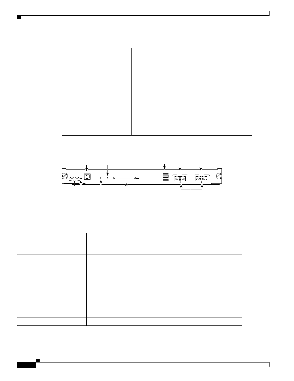
Figure 2-3 Supervisor Engine 32 (WS-SUP32-10GE-3B) Front Panel Features
Status LEDs
Disk LED
CONSOLE port
CompactFlash
Type II slot
Uplink ports
Link Status LEDs
Uplink port
USB ports
Table 2-6 lists and describes Supervisor Engine 32 features.
Ta b l e 2-6 Supervisor Engine 32 Features
Feature Description
Chassis compatibility Supported on all Catalyst 6500 series chassis.
Software requirements
12.2(18)SXF
(minimum)
Fan tray requirements All versions of Supervisor Engine 32 require that a high-speed fan tray
(either a fan tray
2 or Catalyst 6500-E series fan tray) be installed in the
chassis. Low-speed fan trays do not provide sufficient cooling for Supervisor
Engine
32.
Note The high-speed fan trays require that you install a 2500 W or higher
capacity power supply in the chassis to power the fan tray.
Slot installation restrictions Supervisor Engine 32 must be installed in:
120691
• Slots 1 and 2 in a 3-slot or a 4-slot chassis
• Slots 5 and 6 in a 6-slot or a 9-slot chassis
• Slots 7 and 8 in a 13-slot chassis
Note The primary supervisor engine can be installed in either slot.
Backplane 32-Gbps shared bus.
Note Supervisor Engine 32 does not include and does not support switch
fabric.
Catalyst 6500 Series Supervisor Engine Guide
2-8
OL-7397-03
Page 37

Chapter 2 Supervisor Engines
Table 2-6 Supervisor Engine 32 Features (continued)
Feature Description
Hardware restrictions Supervisor Engine 32 does not support:
• WS-F6K-PFC3A Policy Feature Card 3A (PFC3A)
• WS-F6K-PFC3BXL Policy Feature Card 3BXL (PFC3BXL)
• Distributed Forwarding Cards (DFCs).
Note Installed DFCs do not power up with Supervisor Engine 32.
• Switch Fabric Modules (WS-C6500-SFM and WS-X6500-SFM2)
• Ethernet modules not supported include:
–
WS-6716-10GE (16-port 10-Gigabit Ethernet module)
–
WS-6708-10-GE (8-port 10-Gigabit Ethernet module)
–
WS-X6704-10GE (4-port 10-Gigabit Ethernet module)
–
WS-X6748-SFP (48-port Gigabit Ethernet module)
Supervisor Engine 32
–
WS-X6816-GBIC (16-port Gigabit Ethernet module)
–
WS-X6748-GE-TX (48-port 10/100/1000 Ethernet module)
• Optical Service Modules (OSMs)
• WS-X6182-2PA FlexWAN module. (The WS-X6582-2PA Enhanced
FlexWAN module is supported.)
• Service modules not supported include:
–
WS-SVC-WISM-1-K9 Wireless Services Module (WiSM)
–
WS-SVC-AON-1-K9 Application-Oriented Networking (AON)
Module
–
WS-SVC-AGM-1-K9 Anomaly Guard Module
–
WS-SVC-ADM-1-K9 Traffic Anomaly Detector Module
–
WS-SVC-CSG-1 Content Services Gateway module
–
WS-X6066-SLB-APC Content Switching Module (CSM)
–
WS-X6066-SLB-S-K9 Content Switching Module with SSL
(CSM-S)
–
WS-SVC-PSD-1 Persistent Storage Device (PSD) module
–
WS-SVC-WLAN-1-K9 Wireless LAN Services module
–
WS-SVC-IPSEC-1 IPsec VPN Accelerated Forwarding card
OL-7397-03
Catalyst 6500 Series Supervisor Engine Guide
2-9
Page 38

Supervisor Engine 32
Table 2-6 Supervisor Engine 32 Features (continued)
Feature Description
Memory
Switch Processor DRAM • 256 MB (supervisor engines shipped before May, 2005)
• 512 MB (supervisor engines shipped after May, 2005)
• Upgradeable to 1 GB using MEM-xCEF720-1GB memory kit
Route Processor DRAM • 256 MB (supervisor engines shipped before May, 2005)
• 512 MB (supervisor engines shipped after May, 2005)
• Upgradeable to 1 GB using MEM-xCEF720-1GB memory kit
Switch Processor
256 MB
Bootflash/Bootdisk
Route Processor Bootflash 64 MB
CompactFlash (disk0) Compact flash Type 2 (supports 64, 128, 256, 512 MB, and 1 GB
Front panel features
Status LEDs See Ta b l e 2-8 for a list of the status LEDs and their descriptions.
RESET switch The RESET switch allows you to reset and restart the switch.
Chapter 2 Supervisor Engines
Note Because the reset switch is recessed in the faceplate, you must use a
ballpoint pen tip or other small, pointed object to access the switch.
CONSOLE port This is a 10/100/1000 port that uses an RJ-45 connector. The CONSOLE port
allows you to access the switch either locally (with a console terminal) or
remotely (with a modem). The CONSOLE port is an EIA/TIA-232
asynchronous, serial connection with hardware flow control.
DISK 0 (PCMCIA) slot and
LED
One PCMCIA slot is available. The PCMCIA slot allows a Flash PC card to
be installed providing additional flash memory. You can use this flash
memory to store and run software images or to serve as an I/O device. An
eject button is located on the left side, next to the slot. Pushing in on the
button ejects the PCMCIA card from the slot.
The PCMCIA slot has an LED associated with it.
2-10
Catalyst 6500 Series Supervisor Engine Guide
OL-7397-03
Page 39

Chapter 2 Supervisor Engines
Table 2-6 Supervisor Engine 32 Features (continued)
Feature Description
Uplink ports (PORT 1
through PORT
9)
• The WS-SUP32-GE-3B has nine uplink ports: Eight 1000BASE-X SFP
ports and one 10/100/1000BASE RJ-45 port. All nine uplink ports can
be used at one time.
Note The eight 1000BASE-T or 1000BASE-X uplink ports require SFP
transceivers to be installed.
• The WS-SUP32-10GE-3B has three uplink ports: two 10-Gigabit
XENPAK ports and one 10/100/1000BASE RJ-45 port. All three ports
can be used at one time
Note The two 10-Gigabit uplink ports require XENPAK transceivers to be
installed.
Note In chassis configurations where there are redundant supervisor
engines installed, the uplink ports on the supervisor engine that is in
standby mode are fully functional.
Supervisor Engine 32
Each uplink port has a LINK LED associated with it.
Universal Serial Bus (USB)
Two USB 2.0 ports are provided. Currently, they are not enabled.
port
Uplink port queue structure
1p3q8t/2q8t
(Tx/Rx)
Buffer size • WS-SUP32-GE-3B:
–
Total buffer size—10 MB
–
Rx/Tx buffer size—5 MB/5 MB
• Sup32-10GE-3B:
–
Total buffer size—17.7 MB
–
Rx/Tx buffer size—9.6 MB/8.1 MB
Pluggable transceivers
supported
• WS-SUP32-GE-3B—1-GB SFP transceivers are supported in eight
uplink ports.
• WS-SUP32-10GE-3B—10-GB XENPAK transceivers are supported in
the two uplink ports.
Note See Appendix A for a list and a description of the SFP and XENPAK
transceivers that are supported.
Hardware-based forwarding
engine (Policy Feature Card)
The PFC3B is installed on all versions of Supervisor Engine 32
Note The WS-F6K-PFC3A Policy Feature Card 3A (PFC3A) and the
WS-F6K-PFC3BXL Policy Feature Card
supported.
Multilayer Switch Feature Card
MSFC2A
(MSFC) daughter card version
installed
3BXL (PFC3BXL) are not
OL-7397-03
Catalyst 6500 Series Supervisor Engine Guide
2-11
Page 40

Chapter 2 Supervisor Engines
Supervisor Engine 32
Table 2-7 lists the physical and environmental specifications for Supervisor Engine 32.
Ta b l e 2-7 Supervisor Engine 32 Physical and Environmental Specifications
Item Specification
Dimensions (H x W x D) 1.6 x 15.3 x 16.3 in. (4.06 x 38.86 x 41.40 cm). Occupies one slot in the
chassis.
Weight WS-SUP32-GE-3B—9.8 lb (4.45 kg)
WS-SUP32-10GE-3B—9.6 lb (4.35 kg)
Power requirement
• WS-SUP32-GE-3B—3.69 A
(at 42 VDC)
• WS-SUP32-10GE-3B—4.19 A
Environment
Operating temperature • Certified for operation: 32° to 104°F (0° to 40°C)
• Designed and tested for operation: 32° to 130°F (0° to 55°C)
Humidity (RH) ambient
10 to 90%
(noncondensing)
Operating altitude • Certified for operation: 0 to 6500 feet (0 to 2000 m)
• Designed and tested for operation: –200 to 10,000 feet (–60 to 3000 m)
Table 2-8 lists Supervisor Engine 32 front panel LEDs and their meanings.
Ta b l e 2-8 Supervisor Engine 32 Front Panel Status LEDs
LED Color and Meaning
STATUS The STATUS LED indicates the status of the supervisor engine.
• Green—All diagnostics pass. The supervisor engine is
operational (normal initialization sequence).
• Orange—The supervisor engine is booting or running
diagnostics (normal initialization sequence) or an
overtemperature condition has occurred. (A minor temperature
threshold has been exceeded during environmental
monitoring.)
• Red—The diagnostic test failed. The supervisor engine is not
operational because a fault occurred during the initialization
sequence or an overtemperature condition has occurred. (A
major temperature threshold has been exceeded during
environmental monitoring.)
SYSTEM The SYSTEM LED indicates the status of the system components.
2-12
• Green—All chassis environmental monitors are reporting OK.
• Orange—A minor hardware problem has been detected.
• Red—A major hardware problem has occurred.
Catalyst 6500 Series Supervisor Engine Guide
OL-7397-03
Page 41

Chapter 2 Supervisor Engines
Table 2-8 Supervisor Engine 32 Front Panel Status LEDs (continued)
LED Color and Meaning
ACTIVE The ACTIVE LED indicates whether the supervisor engine is
PWR MGMT The supervisor engine monitors each module’s power requirements
DISK 0 (PCMCIA) LED Green—The installed Flash PC card is being accessed and is
LINK The LINK LED indicates the link status of the corresponding port.
Supervisor Engine 32
operating in active mode or is in standby mode.
• Green—The supervisor engine is operational and active.
• Orange—The supervisor engine is in standby mode.
and status relative to the system’s overall power capacity before
fully powering up each module in the chassis.
• Orange—Power-up mode; running self-diagnostics.
• Green—Power management is functioning normally and
sufficient power is available for all modules.
• Orange—A minor power management problem has been
detected. There is insufficient power for all modules to power
up.
• Red—A major power failure has occurred.
performing either a read or a write operation.
For the eight SFP transceiver uplink ports plus the 10/100/1000
copper port, the LED colors indicate the following:
• Green—The port is active (the link is connected and
operational).
• Flashing orange—The port failed diagnostics and is disabled.
• Orange—The port is disabled.
• Red—The supervisor engine is resetting; an overtemperature
condition has occurred.
Note If the supervisor engine fails to download code and
configuration information successfully during the initial
reset, the LED stays red; the supervisor engine does not
come online.
Off—The port is not active or the link is not connected.
For LINK LEDs associated with the XENPAK transceiver uplink
ports, the LED colors indicate the following:
• Green—The XENPAK transceiver is installed, a network
interface cable is attached, and a network link is established.
• Orange—The XENPAK transceiver is installed, the network
interface cable is attached, but there is no network link
established.
• Off—Either the uplink port socket is empty (no XENPAK
transceiver is installed) or the XENPAK transceiver is installed,
but does not have a network cable attached.
OL-7397-03
Catalyst 6500 Series Supervisor Engine Guide
2-13
Page 42

Supervisor Engine 32 PISA
Supervisor Engine 32 PISA
Table 2-9 lists the available versions of Supervisor Engine 32 PISA and provides a brief description of
each. Figure 2-4 shows the faceplate of the WS-S32-GE-PISA with the major features identified.
Figure 2-5 shows the faceplate of the WS-S32-10GE-PISA with the major features identified.
Ta b l e 2-9 Supervisor Engine 32 PISA Product Numbers and Descriptions
Chapter 2 Supervisor Engines
Supervisor Engine 32 Product
Description
Number
WS-S32-GE-PISA The WS-S32-GE-PISA is shipped with a factory-installed
PFC3B daughter card (WS-F6K-PFC3B) and a
Programmable IP Services Accelerator (PISA) daughter
card. The PISA daughter card replaces the MSFC2A
daughter card. Supervisor Engine
32 has nine uplink ports:
eight 1000BASE-X Ethernet uplink ports that require the
installation of Small Form-Factor Pluggable (SFP)
transceivers and one 10/100/1000 port with an RJ-45
connector. Eight uplink ports can be used at one time.
WS-S32-10GE-PISA The WS-S32-10GE-PISA is shipped with a
factory-installed PFC3B daughter card (WS-F6K-PFC3B)
and a Programmable IP Services Accelerator (PISA)
daughter card. The PISA daughter card replaces the
MSFC2A daughter card. Supervisor Engine
32 has three
uplink ports: two 10-Gigabit Ethernet uplink ports that
require the installation of XENPAK transceivers and one
10/100/1000 port with an RJ-45 connector. All three uplink
ports can be used at one time.
Figure 2-4 Supervisor Engine 32 PISA (WS-S32-GE-PISA) Front Panel Features
2-14
Status LEDs
RESET button
Catalyst 6500 Series Supervisor Engine Guide
CONSOLE port
Disk LED
CompactFlash
Type II slot
Uplink ports
Link Status LEDs
Uplink port
186701
USB ports
OL-7397-03
Page 43

Chapter 2 Supervisor Engines
Figure 2-5 Supervisor Engine 32 PISA (WS-S32-10GE-PISA) Front Panel Features
Supervisor Engine 32 PISA
Status LEDs
Disk LED
CONSOLE port
CompactFlash
Type II slot
Uplink ports
Link Status LEDs
Uplink port
186702
USB ports
Table 2-10 lists and describes Supervisor Engine 32 PISA features.
Ta b l e 2-10 Supervisor Engine 32 PISA Features
Feature Description
Chassis compatibility Supported on all Catalyst 6500 series chassis.
Software requirements
(minimum)
• WS-S32-GE-PISA—12.2(18)ZY
• WS-S32-10GE-PISA—12.2(18)ZY1
Fan tray requirements Both versions of Supervisor Engine 32 PISA require that a high-speed fan tray
(either a fan tray
Low-speed fan trays do not provide sufficient cooling for Supervisor Engine
2 or Catalyst 6500-E series fan tray) be installed in the chassis.
32
PISA.
Note The high-speed fan trays require that you install a 2500 W or higher
capacity power supply in the chassis to power the fan tray.
Slot installation restrictions Supervisor Engine 32 PISA must be installed in:
• Slots 1 and 2 in a 3-slot or a 4-slot chassis
• Slots 5 and 6 in a 6-slot or a 9-slot chassis
• Slots 7 and 8 in a 13-slot chassis
Note The primary supervisor engine can be installed in either slot.
Backplane 32-Gbps shared bus.
Note Supervisor Engine 32 PISA does not include and does not support
switch fabric.
OL-7397-03
Catalyst 6500 Series Supervisor Engine Guide
2-15
Page 44

Supervisor Engine 32 PISA
Table 2-10 Supervisor Engine 32 PISA Features (continued)
Feature Description
Hardware restrictions Supervisor Engine 32 PISA does not support:
• WS-F6K-PFC3A Policy Feature Card 3A (PFC3A)
• WS-F6K-PFC3BXL Policy Feature Card 3BXL (PFC3BXL)
• Distributed Forwarding Cards (DFCs).
Note Installed DFCs do not power up with Supervisor Engine 32 PISA.
• Switch Fabric Modules (WS-C6500-SFM and WS-X6500-SFM2)
• Ethernet modules not supported include:
–
WS-X6704-10GE (4-port 10-Gigabit Ethernet module)
–
WS-X6748-SFP (48-port Gigabit Ethernet module)
–
WS-X6816-GBIC (16-port Gigabit Ethernet module)
–
WS-X6748-GE-TX (48-port 10/100/1000 Ethernet module)
Chapter 2 Supervisor Engines
• Optical Service Modules (OSMs)
• WS-X6182-2PA FlexWAN module. (The WS-X6582-2PA Enhanced
FlexWAN module is supported.)
• Service modules not supported include:
–
WS-SVC-WISM-1-K9 Wireless Services Module (WiSM)
–
WS-SVC-AON-1-K9 Application-Oriented Networking (AON)
Module
–
WS-SVC-AGM-1-K9 Anomaly Guard Module
–
WS-SVC-ADM-1-K9 Traffic Anomaly Detector Module
–
WS-SVC-CSG-1 Content Services Gateway module
–
WS-X6066-SLB-APC Content Switching Module (CSM)
–
WS-X6066-SLB-S-K9 Content Switching Module with SSL (CSM-S)
–
WS-SVC-PSD-1 Persistent Storage Device (PSD) module
–
WS-SVC-WLAN-1-K9 Wireless LAN Services module
–
WS-SVC-IPSEC-1 IPsec VPN Accelerated Forwarding card
2-16
Catalyst 6500 Series Supervisor Engine Guide
OL-7397-03
Page 45

Chapter 2 Supervisor Engines
Supervisor Engine 32 PISA
Table 2-10 Supervisor Engine 32 PISA Features (continued)
Feature Description
Memory
Switch Processor DRAM • 512 MB (WS-S32-GE-PISA)
• 1 GB (WS-S32-10GE-PISA)
Route Processor DRAM 1 GB
Switch Processor
512 MB through internal compact flash (bootdisk in CLI); upgradeable to 1 GB
Bootflash/Bootdisk
Route Processor Bootflash 256 MB
CompactFlash (disk0) Compact flash Type 2 (supports 64, 128, 256, 512 MB, and 1 GB
Front panel features
Status LEDs See Ta b l e 2-12 for a list of the status LEDs and their descriptions.
RESET switch The RESET switch allows you to reset and restart the switch.
Note Because the reset switch is recessed in the faceplate, you must use a
ballpoint pen tip or other small, pointed object to access the switch.
CONSOLE port This is a 10/100/1000 port that uses an RJ-45 connector. The CONSOLE port
allows you to access the switch either locally (with a console terminal) or
remotely (with a modem). The CONSOLE port is an EIA/TIA-232
asynchronous, serial connection with hardware flow control.
DISK 0 (PCMCIA) slot and
LED
One PCMCIA slot is available. The PCMCIA slot allows a Flash PC card to be
installed providing additional flash memory. You can use this flash memory to
store and run software images or to serve as an I/O device. An eject button is
located on the left side, next to the slot. Pushing in on the button ejects the
PCMCIA card from the slot.
The PCMCIA slot has an LED associated with it.
OL-7397-03
Catalyst 6500 Series Supervisor Engine Guide
2-17
Page 46

Supervisor Engine 32 PISA
Table 2-10 Supervisor Engine 32 PISA Features (continued)
Feature Description
Uplink ports (PORT 1
through PORT
9)
• The WS-S32-GE-PISA have nine uplink ports:
–
Eight 1000BASE-X SFP ports and
–
One 10/100/1000BASE RJ-45 port.
All nine uplink ports can be used at one time.
Note The eight 1000BASE-T or 1000BASE-X uplink ports require SFP
transceivers to be installed.
• The WS-S32-10GE-PISA have three uplink ports:
–
Two 10-Gigabit XENPAK ports
–
One 10/100/1000BASE RJ-45 port.
All three ports can be used at one time
Note The two 10-Gigabit uplink ports require XENPAK transceivers to be
installed.
Chapter 2 Supervisor Engines
Note In chassis configurations where there are redundant supervisor engines
installed, the uplink ports on the supervisor engine that is in standby
mode are fully functional.
Each uplink port has a LINK LED associated with it.
Unmarked RJ-45 port The unmarked RJ-45 port, located above the PCMCIA slot, is currently not
supported by the software and is disabled.
Universal Serial Bus (USB)
Two USB 2.0 ports are provided. Currently, they are not enabled.
port
Uplink port queue structure
1p3q8t/2q8t
(Tx/Rx)
Buffer size • WS-S32-GE-PISA—9.5 MB per port
• WS-S32-10GE-PISA—100 MB per 10-gigabit port
Pluggable transceivers
supported
• WS-SUP32-GE-PISA—Eight 1-GB SFP transceivers are supported.
• WS-S32-10GE-PISA—Two 10-GB XENPAK transceivers are supported.
Note See Appendix A for a list and a description of the SFP and XENPAK
transceivers that are supported.
Hardware-based forwarding
engine (Policy Feature Card)
The PFC3B is installed on both versions of Supervisor Engine 32 PISA
Note The WS-F6K-PFC3A Policy Feature Card 3A (PFC3A) and the
WS-F6K-PFC3BXL Policy Feature Card
3BXL (PFC3BXL) are not
supported.
Programmable IP Services
Accelerator (PISA)
The PISA daughter card replaces the MSFC2A daughter card. The PISA
daughter card integrates the MSFC2A functions and provides additional
functionality.
2-18
Catalyst 6500 Series Supervisor Engine Guide
OL-7397-03
Page 47

Chapter 2 Supervisor Engines
Supervisor Engine 32 PISA
Table 2-11 lists the physical and environmental specifications for Supervisor Engine 32 PISA.
Ta b l e 2-11 Supervisor Engine 32 PISA Physical and Environmental Specifications
Item Specification
Dimensions (H x W x D) 1.6 x 15.3 x 16.3 in. (4.06 x 38.86 x 41.40 cm). Occupies one slot in the
chassis.
Weight WS-S32-GE-PISA—9.7 lb (4.4 kg)
WS-S32-10GE-PISA—9.5 lb (4.3 kg)
Power requirement
• WS-S32-GE-PISA—2.96 A
(at 42 VDC)
• WS-S32-10GE-PISA—2.97 A
Environment
Operating temperature • Certified for operation: 32° to 104°F (0° to 40°C)
• Designed and tested for operation: 32° to 130°F (0° to 55°C)
Humidity (RH) ambient
10 to 90%
(noncondensing)
Operating altitude • Certified for operation: 0 to 6500 feet (0 to 2000 m)
• Designed and tested for operation: –200 to 10,000 feet (–60 to 3000 m)
Table 2-12 lists Supervisor Engine 32 PISA front panel LEDs and their meanings.
Ta b l e 2-12 Supervisor Engine 32 PISA Front Panel Status LEDs
LED Color and Meaning
STATUS The STATUS LED indicates the status of the supervisor engine.
• Green—All diagnostics pass. The supervisor engine is
operational (normal initialization sequence).
• Orange—The supervisor engine is booting or running
diagnostics (normal initialization sequence) or an
overtemperature condition has occurred. (A minor temperature
threshold has been exceeded during environmental
monitoring.)
• Red—The diagnostic test failed. The supervisor engine is not
operational because a fault occurred during the initialization
sequence or an overtemperature condition has occurred. (A
major temperature threshold has been exceeded during
environmental monitoring.)
SYSTEM The SYSTEM LED indicates the status of the system components.
OL-7397-03
• Green—All chassis environmental monitors are reporting OK.
• Orange—A minor hardware problem has been detected.
• Red—A major hardware problem has occurred.
Catalyst 6500 Series Supervisor Engine Guide
2-19
Page 48

Supervisor Engine 32 PISA
Table 2-12 Supervisor Engine 32 PISA Front Panel Status LEDs (continued)
LED Color and Meaning
ACTIVE The ACTIVE LED indicates whether the supervisor engine is
PWR MGMT The supervisor engine monitors each module’s power requirements
LINK The LINK LED indicates the link status of the corresponding port.
Chapter 2 Supervisor Engines
operating in active mode or is in standby mode.
• Green—The supervisor engine is operational and active.
• Orange—The supervisor engine is in standby mode.
and status relative to the system’s overall power capacity before
fully powering up each module in the chassis.
• Orange—Power-up mode; running self-diagnostics.
• Green—Power management is functioning normally and
sufficient power is available for all modules.
• Orange—A minor power management problem has been
detected. There is insufficient power for all modules to power
up.
• Red—A major power failure has occurred.
For the eight SFP uplink ports plus the 10/100/1000 copper port, the
LED colors indicate the following:
• Green—The port is active (the link is connected and
operational).
• Flashing orange—The port failed diagnostics and is disabled.
• Orange—The port is disabled.
• Red—The supervisor engine is resetting; an overtemperature
condition has occurred.
Note If the supervisor engine fails to download code and
configuration information successfully during the initial
reset, the LED stays red; the supervisor engine does not
come online.
Off—The port is not active or the link is not connected.
For LINK LEDs associated with the XENPAK uplink ports, the
LED colors indicate the following:
• Green—The XENPAK transceiver is installed, a network
interface cable is attached, and a network link is established.
• Orange—The XENPAK transceiver is installed, the network
interface cable is attached, but there is no network link
established.
• Off—Either the uplink port socket is empty (no XENPAK
transceiver is installed) or the XENPAK transceiver is installed,
but does not have a network cable attached.
DISK 0 (PCMCIA) LED Green—The installed Flash PC card is being accessed and is
performing either a read or a write operation.
2-20
Catalyst 6500 Series Supervisor Engine Guide
OL-7397-03
Page 49

Chapter 2 Supervisor Engines
Supervisor Engine 720
Table 2-13 lists the available versions of Supervisor Engine 720 and provides a brief description of each.
Figure 2-6 shows the faceplate of Supervisor Engine 720 with the major features identified.
Ta b l e 2-13 Supervisor Engine 720 Versions
Supervisor Engine 720
Supervisor Engine 720 Product
Description
Numbers
WS-SUP720 Supervisor Engine 720 (WS-SUP720) is shipped with a
factory-installed PFC3A daughter card (WS-F6K-PFC3A) and
a factory-installed MSFC3 daughter card (WS-F6K-MSFC3).
Supervisor Engine
720 has three uplink ports: two
1000BASE-X Ethernet uplink ports that require the
installation of GBIC transceivers and one 10/100/100 port
equipped with an RJ-45 connector. Only two ports can be used
at a time.
WS-SUP720-3B Supervisor Engine 720 (WS-SUP720-3B) is shipped with a
factory-installed PFC3B daughter card (WS-F6K-PFC3B) and
a factory-installed MSFC3 daughter card (WS-F6K-MSFC3).
Supervisor Engine
720 has three uplink ports: two
1000BASE-X Ethernet uplink ports that require the
installation of GBIC transceivers and one 10/100/100 port
equipped with an RJ-45 connector. Only uplink two ports can
be used at a time.
WS-SUP720-3BXL Supervisor Engine 720 (WS-SUP720-3BXL) is shipped with a
factory-installed PFC3BXL daughter card
(WS-F6K-PFC3BXL) and a factory-installed MSFC3
daughter card (WS-F6K-MSFC3). Supervisor Engine
720 has
three uplink ports: two 1000BASE-X Ethernet uplink ports
that require the installation of GBIC transceivers and one
10/100/100 port equipped with an RJ-45 connector. Only two
uplink ports can be used at a time.
OL-7397-03
Figure 2-6 Supervisor Engine 720 Front Panel Features
STATUS LEDs
Disk LEDs
CompactFlash
Type II slots
CONSOLE port
LINK LEDs
Gigabit Ethernet
uplink port
Catalyst 6500 Series Supervisor Engine Guide
87890
10/100/1000 uplink port
2-21
Page 50

Chapter 2 Supervisor Engines
Supervisor Engine 720
Table 2-14 lists and describes Supervisor Engine 720 features.
Ta b l e 2-14 Supervisor Engine 720 Features
Feature Description
Chassis compatibility Supported on all Catalyst 6500 series chassis.
Software requirements
(minimum)
• Supervisor Engine 720—12.2(14)SX
• Supervisor Engine 720-3B—12.2(17d)SXB1
• Supervisor Engine 720-3BXL—12.2(17b)SXA
Fan tray requirements All versions of Supervisor Engine 720 require that a high-speed fan tray
(either a fan tray
2 or Catalyst 6500-E series fan tray) be installed in the
chassis.
Note Low-speed fan trays do not provide sufficient cooling for Supervisor
Engine
720.
Slot installation restrictions Supervisor Engine 720 must be installed in:
• Slots 1 and 2 in a 3-slot or a 4-slot chassis
• Slots 5 and 6 in a 6-slot or a 9-slot chassis
• Slots 7 and 8 in a 13-slot chassis
Note The primary supervisor engine can be installed in either slot.
Backplane 32-Gbps shared bus
Integrated 720-Gbps Switch Fabric
Hardware restrictions There are no additional hardware restrictions for Supervisor Engine 720.
Memory
Switch Processor DRAM • 512 MB (WS-SUP720)
• 512 MB (WS-SUP720-3B)
• 1 GB (WS-SUP720-3BXL)
Route Processor DRAM • 512 MB (WS-SUP720)
• 512 MB (WS-SUP720-3B)
• 1 GB (WS-SUP720-3BXL)
Switch Processor
Bootflash/Bootdisk
For all three Supervisor Engine 720 models:
• 64 MB (before May 5, 2006)
• 512 MB (after May 5, 2006)
Note Use upgrade kit WS-CF-UPG= to upgrade the bootflash from 64 MB
to 512
MB.
Route Processor Bootflash For all three Supervisor Engine 720 models—64 MB
CompactFlash (disk0) Compact flash Type 2 (supports 64, 128, 256, 512 MB, and 1 GB
2-22
Catalyst 6500 Series Supervisor Engine Guide
OL-7397-03
Page 51

Chapter 2 Supervisor Engines
Table 2-14 Supervisor Engine 720 Features (continued)
Feature Description
Front panel features
Status LEDs See Ta b l e 2-16 for a list of the status LEDs and their descriptions.
RESET switch The RESET switch allows you to reset and restart the switch.
Note Because the reset switch is recessed in the faceplate, you must use a
ballpoint pen tip or other small, pointed object to access the switch.
CONSOLE port This is a 10/100/1000 port that uses an RJ-45 connector. The CONSOLE port
allows you to access the switch either locally (with a console terminal) or
remotely (with a modem). The CONSOLE port is an EIA/TIA-232
asynchronous, serial connection with hardware flow control.
DISK 0 and DISK 1 slot and
LEDs
Two PCMCIA slots are available. The PCMCIA slots allow a Flash PC card
to be installed providing additional flash memory. You can use this flash
memory to store and run software images or to serve as an I/O device. An
eject button is located on the left side, next to each slot. Pushing in on the
button ejects the Flash PC card from the slot. The slot supports 64, 128, 256,
512
MB, and 1 GB Flash PC cards.
Supervisor Engine 720
Uplink ports (PORT 1 and
PORT
2)
Each PCMCIA slot has an LED associated with it.
• Supervisor Engine 720 has three uplink ports: Two 1000BASE-X SFP
ports and one 10/100/1000BASE RJ-45 port. Only two ports can be
active at one time.
Note The two 1000BASE-T or 1000BASE-X uplink ports require SFP
transceivers to be installed.
Note In chassis configurations where there are redundant supervisor
engines installed, the uplink ports on the supervisor engine that is in
standby mode are fully functional.
Each uplink port has a LINK LED associated with it. The LINK LED
indicates the link status of the corresponding port.
• Green—The port is active (the link is connected and operational).
• Flashing orange—The port failed diagnostics and is disabled.
• Orange—The port is disabled.
• Red—The supervisor engine is resetting; an overtemperature condition
has occurred.
Note If the supervisor engine fails to download code and configuration
information successfully during the initial reset, the LED stays red;
the supervisor engine does not come online.
OL-7397-03
• Off—The port is not active or the link is not connected.
Catalyst 6500 Series Supervisor Engine Guide
2-23
Page 52

Supervisor Engine 720
Table 2-14 Supervisor Engine 720 Features (continued)
Feature Description
Uplink port queue structure • Tx—1p2q2t
• Rx—1p1q4t
Buffer size • Total buffer size—512 KB
• Rx/Tx buffer size—80 KB/432 KB
Pluggable transceivers
supported
Supports SFP transceivers in the uplink ports.
Note See Appendix A for a list and a description of the SFP transceivers
that are supported.
Hardware-based forwarding
engine (Policy Feature Card)
Multilayer Switch Feature Card
• WS-SUP720—PFC3A (WS-F6K-PFC3A)
• WS-SUP720-3B—PFC3B (WS-F6K-PFC3B)
• WS-SUP720-3BXL—PFC3BXL (WS-F6K-PFC3BXL)
• MSFC3 (WS-F6K-MSFC3) on all Supervisor Engine 720 versions.
(MSFC) daughter card version
installed
Chapter 2 Supervisor Engines
Table 2-15 lists Supervisor Engine 720 physical and environmental specifications.
Ta b l e 2-15 Supervisor Engine 720 Physical and Environmental Specifications
Item Specification
Dimensions (H x W x D) 1.6 x 15.3 x 16.3 in. (4.06 x 38.86 x 41.40 cm). Occupies one slot in the
chassis.
Weight • WS-SUP720—11.5 lb
• WS-SUP720-3B—11.6 lb
• WS-SUP720-3BXL—11.8 lb
Power requirement
(at 42 VDC)
• WS-SUP720—7.5 A
• WS-SUP720-3B—6.72 A
• WS-SUP720-3BXL—7.82 A
Environment
Operating temperature • Certified for operation: 32° to 104°F (0° to 40°C)
• Designed and tested for operation: 32° to 130°F (0° to 55°C)
Humidity (RH) ambient
10 to 90%
(noncondensing)
Operating altitude • Certified for operation: 0 to 6500 feet (0 to 2000 meters)
2-24
• Designed and tested for operation: –200 to 10,000 feet (–60 to
3000
meters)
Catalyst 6500 Series Supervisor Engine Guide
OL-7397-03
Page 53

Chapter 2 Supervisor Engines
Table 2-16 lists Supervisor Engine 720 front panel LEDs and their meanings.
Ta b l e 2-16 Supervisor Engine 720 Front Panel Status LEDs
LED Color and Meaning
STATUS The STATUS LED indicates the status of the supervisor engine.
SYSTEM The SYSTEM LED indicates the status of the system components.
Supervisor Engine 720
• Green—All diagnostics pass. The supervisor engine is
operational (normal initialization sequence).
• Orange—The supervisor engine is booting or running
diagnostics (normal initialization sequence) or an
overtemperature condition has occurred. (A minor temperature
threshold has been exceeded during environmental
monitoring.)
• Red—The diagnostic test failed. The supervisor engine is not
operational because a fault occurred during the initialization
sequence or an overtemperature condition has occurred. (A
major temperature threshold has been exceeded during
environmental monitoring.)
• Green—All chassis environmental monitors are reporting OK.
• Orange—A minor hardware problem has been detected.
• Red—A major hardware problem has occurred
ACTIVE The ACTIVE LED indicates whether the supervisor engine is
operating in active mode or is in standby mode.
• Green—The supervisor engine is operational and active.
• Orange—The supervisor engine is in standby mode.
PWR MGMT The supervisor engine monitors each module’s power requirements
and status relative to the system’s overall power capacity before
fully powering up each module in the chassis.
• Orange—Power-up mode; running self-diagnostics.
• Green—Power management is functioning normally and
sufficient power is available for all modules.
• Orange—A minor power management problem has been
detected. There is insufficient power for all modules to power
up.
• Red—A major power failure has occurred.
DISK 0 and DISK 1 LEDs These LEDs are illuminated green when the installed Flash PC card
is being accessed and is performing either a read operation or a
write operation.
OL-7397-03
Catalyst 6500 Series Supervisor Engine Guide
2-25
Page 54

Supervisor Engine 720-10GE
Supervisor Engine 720-10GE
Table 2-17 lists the available versions of Supervisor Engine 720-10GE and provides a brief description
of each. Figure 2-7 shows the faceplate of Supervisor Engine 720-10GE with the major features
identified.
Ta b l e 2-17 Supervisor Engine 720-10GE Models
Chapter 2 Supervisor Engines
Supervisor Engine 720 Product
Description
Numbers
Supervisor Engine 720-10GE
(VS-S720-10G-3C)
Supervisor Engine 720 (VS-S720-10G-3C) is shipped with a
factory-installed PFC3C daughter card (WS-F6K-PFC3C) and
a factory-installed MSFC3 daughter card (WS-F6K-MSFC3).
Supervisor Engine
720 has five uplink ports: two 10GBASE-X
Ethernet ports that require the installation of X2 transceivers,
two 1000BASE-X Ethernet ports that require SFP transceivers,
and one 10/100/100 port equipped with an RJ-45 connector.
Supervisor Engine 720-10GE
(VS-S720-10G-3CXL)
Supervisor Engine 720 (VS-S720-10G-3CXL) is shipped with
a factory-installed PFC3CXL daughter card
(WS-F6K-PFC3CXL) and a factory-installed MSFC3
daughter card (WS-F6K-MSFC3). Supervisor
Engine
720-10GE has five uplink ports: two 10GBASE-X
Ethernet ports that require the installation of X2 transceivers,
two 1000BASE-X Ethernet ports that require SFP transceivers,
and one 10/100/100 port equipped with an RJ-45 connector.
Figure 2-7 Supervisor Engine 720-10GE Front Panel Features
CONSOLE
port
10/100/100
3
CONSOLE
Note:
CompactFlash
latch removed for
clarity
10-GE uplink
ports
10GE UPLINK
4
LINK
LINK
LEDs
LINK
Disk LED
VS-S720-10G
EJECT
ACTIVE
STATUS SYSTEM
SUPERVISOR 720 WITH INTEGRATED SWITCH FABRIC/PFC3
PWR MGMT
STATUS
LEDs
1-GE uplink
DISK 0
RESET
CompactFlash
Type II slot
ports
10/100/1000
uplink port
UPLINK
SFP
3
1
LINK LINKLINK
LINK
LEDs
5
186480
USB ports
2-26
Catalyst 6500 Series Supervisor Engine Guide
OL-7397-03
Page 55

Chapter 2 Supervisor Engines
Supervisor Engine 720-10GE
Table 2-18 lists and describes Supervisor Engine 720-10GE features.
Ta b l e 2-18 Supervisor Engine 720-10GE Features
Feature Description
Chassis compatibility Supported on all Catalyst 6500 series chassis.
Software requirements
(minimum)
12.2(33)SHX
Note If there are no DFC-equipped modules installed, certain
configurations require Release 12.2(33)SXH1 or later and impose
configuration restrictions. Refer to your software release notes for
further information.
Fan tray requirements All versions of Supervisor Engine 720-10GE require that a high-speed fan
tray (either a fan tray
2 or Catalyst 6500-E series fan tray) be installed in the
chassis.
Note Low-speed fan trays do not provide sufficient cooling for Supervisor
Engine
720-10GE.
Slot installation restrictions Supervisor Engine 720-10GE must be installed in:
• Slots 1 and 2 in a 3-slot or a 4-slot chassis
• Slots 5 and 6 in a 6-slot or a 9-slot chassis
• Slots 7 and 8 in a 13-slot chassis
Note The primary supervisor engine can be installed in either slot.
Backplane 32-Gbps shared bus
Integrated 720-Gbps Switch Fabric
Hardware restrictions There are no additional hardware restrictions for Supervisor
Engine
720-10GE.
OL-7397-03
Catalyst 6500 Series Supervisor Engine Guide
2-27
Page 56

Chapter 2 Supervisor Engines
Supervisor Engine 720-10GE
Table 2-18 Supervisor Engine 720-10GE Features (continued)
Feature Description
Memory
Switch Processor DRAM 1 GB
Route Processor DRAM 1 GB
Switch Processor
1 GB
Bootflash/Bootdisk
Route Processor Bootflash 64 MB
CompactFlash (disk0) Compact flash Type 2 (supports 64, 128, 256, 512 MB, and 1 GB
Front panel features
Status LEDs See Ta b l e 2-20 for a list of the status LEDs and their descriptions.
RESET switch The RESET switch allows you to reset and restart the switch.
Note Because the reset switch is recessed in the faceplate, you must use a
ballpoint pen tip or other small, pointed object to access the switch.
CONSOLE port This is a 10/100/1000 port that uses an RJ-45 connector. The CONSOLE port
allows you to access the switch either locally (with a console terminal) or
remotely (with a modem). The CONSOLE port is an EIA/TIA-232
asynchronous, serial connection with hardware flow control.
Universal Serial Bus (USB)
Two USB 2.0 ports are provided. Currently, they are not enabled.
port
DISK 0 slot and LED One PCMCIA slot is available. The PCMCIA slots allow a Flash PC card to
be installed providing additional flash memory. You can use this flash
memory to store and run software images or to serve as an I/O device. An
eject button is located on the left side, next to each slot. Pushing in on the
button ejects the Flash PC card from the slot. The slot supports 256
512
MB, and 1 GB Flash PC cards.
The PCMCIA slot has an LED associated with it.
Uplink ports (PORT 1
through PORT
5)
• Supervisor Engine 720-10GE has five uplink ports:
–
Two 10GBASE-X ports
MB,
2-28
–
Two 1000BASE-X ports
–
One 10/100/1000BASE RJ-45 port
Note The two 10GBASE-X ports require X2 transceiver modules; the two
1000BASE-X uplink ports require SFP transceiver modules.
Note In chassis configurations where there are redundant supervisor
engines installed, the uplink ports on the supervisor engine that is in
standby mode are fully functional.
• Each uplink port has a link LED associated with it.
Catalyst 6500 Series Supervisor Engine Guide
OL-7397-03
Page 57

Chapter 2 Supervisor Engines
Table 2-18 Supervisor Engine 720-10GE Features (continued)
Feature Description
Uplink port queue structure • 1000BASE-X (uplink ports 1 and 2)
–
Tx—1p3q4t
–
Rx—2q4t
• 10/100/1000 Mbps (uplink port 3)
–
Tx—1p3q4t
–
Rx—2q4t
• 10GBASE-X (uplink ports 4 and 5) (1000BASE-X ports inactive)
–
Tx—1p7q4t
–
Rx—8q4t (VS-S720-10G-3C); 2q8t (VS-S720-10G-3CXL)
• 10GBASE-X (uplink ports 4 and 5) (1000BASE-X ports active)
–
Tx—1p3q4t
–
Rx—2q4t
Buffer size • 10GBASE port—191.8 MB per port
• 1000BASE port—17.7 MB per port
Pluggable transceivers
supported
• Supports SFP 1-GBASE-X transceivers in Ports 1 and 2.
• Supports X2 10-GBASE-X transceivers in Ports 4 and 5.
Supervisor Engine 720-10GE
Hardware-based forwarding
engine (Policy Feature Card)
Multilayer Switch Feature Card
(MSFC) daughter card version
installed
Note See Appendix A for a list and a description of the X2 and SFP
transceivers that are supported.
• VS-S720-10G-3C—PFC3C (WS-F6K-PFC3C)
• VS-S720-10G-3CXL—PFC3CXL (WS-F6K-PFC3CXL)
• MSFC3 (WS-F6K-MSFC3)
OL-7397-03
Catalyst 6500 Series Supervisor Engine Guide
2-29
Page 58

Chapter 2 Supervisor Engines
Supervisor Engine 720-10GE
Table 2-19 lists the physical and environmental specifications for Supervisor Engine 720-10GE.
Ta b l e 2-19 Supervisor Engine 720-10GE Physical and Environmental Specifications
Item Specification
Dimensions (H x W x D) 1.6 x 15.3 x 16.3 in. (4.06 x 38.86 x 41.40 cm). Occupies one slot in the
chassis.
Weight 11.5 lb (5.22 kg)
Power requirement
(at 42 VDC)
• Supervisor Engine 720-10G (VS-S720-10G-3C)—8.05 A
• Supervisor Engine 720-10G (VS-S720-10G-3CXL)—8.65 A
Environment
Operating temperature • Certified for operation: 32° to 104°F (0° to 40°C)
• Designed and tested for operation: 32° to 130°F (0° to 55°C)
Humidity (RH) ambient
10 to 90%
(noncondensing)
Operating altitude • Certified for operation: 0 to 6500 feet (0 to 2000 m)
• Designed and tested for operation: –200 to 10,000 feet (–60 to 3000 m)
2-30
Catalyst 6500 Series Supervisor Engine Guide
OL-7397-03
Page 59

Chapter 2 Supervisor Engines
Table 2-20 lists Supervisor Engine 720-10GE front panel LEDs and their meanings.
Ta b l e 2-20 Supervisor Engine 720-10GE Front Panel Status LEDs
LED Color and Meaning
STATUS The STATUS LED indicates the status of the supervisor engine.
SYSTEM The SYSTEM LED indicates the status of the system components.
Supervisor Engine 720-10GE
• Green—All diagnostics pass. The supervisor engine is
operational (normal initialization sequence).
• Orange—The supervisor engine is booting or running
diagnostics (normal initialization sequence) or an
overtemperature condition has occurred. (A minor temperature
threshold has been exceeded during environmental
monitoring.)
• Red—The diagnostic test failed. The supervisor engine is not
operational because a fault occurred during the initialization
sequence or an overtemperature condition has occurred. (A
major temperature threshold has been exceeded during
environmental monitoring.)
• Green—All chassis environmental monitors are reporting OK.
• Orange—A minor hardware problem has been detected.
• Red—A major hardware problem has occurred.
ACTIVE The ACTIVE LED indicates whether the supervisor engine is
operating in active mode or is in standby mode.
• Green—The supervisor engine is operational and active.
• Orange—The supervisor engine is in standby mode.
PWR MGMT The supervisor engine monitors each module’s power requirements
and status relative to the system’s overall power capacity before
fully powering up each module in the chassis.
• Orange—Power-up mode; running self-diagnostics.
• Green—Power management is functioning normally and
sufficient power is available for all modules.
• Orange—A minor power management problem has been
detected. There is insufficient power for all modules to power
up.
• Red—A major power failure has occurred.
OL-7397-03
Catalyst 6500 Series Supervisor Engine Guide
2-31
Page 60

Supervisor Engine 720-10GE
Table 2-20 Supervisor Engine 720-10GE Front Panel Status LEDs (continued)
LED Color and Meaning
DISK 0 This LED is illuminated green when the installed Flash PC card is
LINK Each uplink port has a LINK LED associated with it. The LINK
Chapter 2 Supervisor Engines
being accessed and is performing either a read operation or a write
operation.
LED indicates the link status of the corresponding port.
• Green—The port is active (the link is connected and
operational).
• Flashing orange—The port failed diagnostics and is disabled.
• Orange—The port is disabled.
• Red—The supervisor engine is resetting; an overtemperature
condition has occurred.
Note If the supervisor engine fails to download code and
configuration information successfully during the initial
reset, the LED stays red; the supervisor engine does not
come online.
• Off—The port is not active or the link is not connected.
2-32
Catalyst 6500 Series Supervisor Engine Guide
OL-7397-03
Page 61

Chapter 2 Supervisor Engines
Supervisor Engine 2T
Table 2-21 lists the available versions of Supervisor Engine 2T and provides a brief description of each.
Figure 2-8 shows the faceplate of Supervisor Engine 2T with the major features identified.
Ta b l e 2-21 Supervisor Engine 2T Models
Supervisor Engine 2T
Supervisor Engine 720 Product
Description
Numbers
VS-S2T-10G The VS-S2T-10G is shipped with a factory-installed PFC4
daughter card (VS-F6K-PFC4) and a factory-installed MSFC5
daughter card (VS-F6K-MSFC5). There are five uplink ports:
two 10GBASE-X Ethernet ports that require the installation of
X2 transceivers and three 1000BASE-X Ethernet ports that
require SFP transceivers.
VS-S2T-10G-XL The VS-S2T-10G-XL is shipped with a factory-installed
PFC4XL daughter card (VS-F6K-PFC4XL) and a
factory-installed MSFC5 daughter card (VS-F6K-MSFC5).
There are five uplink ports: two 10GBASE-X Ethernet ports
that require the installation of X2 transceivers and three
1000BASE-X Ethernet ports that require SFP transceivers.
Figure 2-8 Supervisor Engine 2T Front Panel Features
VS-S720-10G
EJECT
STATUSIDSYSTEM
SUPERVISOR 720 WITH INTEGRATED SWITCH FABRIC/PFC3
PWR MGMT
ACTIVE
7
DISK 0
RESET
8
SFP UPLINK
1
2
LINK LINK
LINK
9 10 12 13
3
LINK
MANAGEMENT
CONSOLE
11
10GE UPLINK
4
LINK
5
LINK
USB
255278
OL-7397-03
1
3
2
4
6
5
1 STATUS LED 8 1000BASE-X UPLINK ports (requires SFP
transceivers)
2 ID LED 9 MANAGEMENT port
3 SYSTEM LED 10 CONSOLE port
4 ACTIVE LED 11 10GBASE-X UPLINK ports (requires X2
transceivers
5 PWR MGMT LED 12 USB port
6 RESET switch 13 Port currently not supported
7 PCMCIA slot
Catalyst 6500 Series Supervisor Engine Guide
2-33
Page 62

Chapter 2 Supervisor Engines
Supervisor Engine 2T
Table 2-22 lists and describes Supervisor Engine 2T features.
Ta b l e 2-22 Supervisor Engine 2T Features
Feature Description
Chassis compatibility Supported only on all Catalyst 6500 E-series chassis.
Software requirements
12.2(50)SY
(minimum)
Fan tray requirements Both versions of the Supervisor Engine 2T require that a high-speed fan tray
be installed in the chassis.
Note Low-speed fan trays do not provide sufficient cooling for Supervisor
Engine
2T.
Slot installation restrictions Supervisor Engine 2T must be installed in:
• Slots 1 and 2 in a 3-slot or a 4-slot chassis
• Slots 5 and 6 in a 6-slot or a 9-slot chassis
• Slots 7 and 8 in a 13-slot chassis
Note The primary supervisor engine can be installed in either slot.
Note When the Supervisor Engine 2T is installed in a chassis with either
a WS-X69xx or a WS-X68xx module, there is a requirement that the
two slots adjacent to the supervisor engine and the module either
have a module installed in them or, if the slots are unused, have a
switching-module filler plate (Cisco part number SLOTBLANK-09
or WS-X6K-SLOT-CVR-E) installed for NEBS compliance. Do not
use blank slot covers (WS-X6K-SLOT-CVR) to cover the adjacent
unused slots.
Hardware restrictions • Supported only in Catalyst 6500 E-series switches.
• Supports only modules equipped with the DFC4-A, DFC4-AXL,
DFC4-E, DFC4-EXL, or the CFC daughter cards. Modules equipped
with DFC3 daughter cards are not supported. For further information on
hardware restrictions and module support, refer to the software release
notes at the following URL:
http://www.cisco.com/en/US/docs/switches/lan/catalyst6500/ios/12.2S
Y/release/notes/ol_20679.html
2-34
Catalyst 6500 Series Supervisor Engine Guide
OL-7397-03
Page 63

Chapter 2 Supervisor Engines
Table 2-22 Supervisor Engine 2T Features (continued)
Feature Description
Memory
DRAM 2 GB
External CompactFlash
Compact flash Type 2 (1 GB)
(disk0)
Front panel features
Status LEDs See Ta b l e 2-24 for a list of the status LEDs and their descriptions.
RESET switch The RESET switch allows you to reset and restart the switch.
Note Because the reset switch is recessed in the supervisor engine
faceplate, you must use a ballpoint pen tip or other small, pointed
object to access the switch.
CONSOLE port This is a 10/100/1000 port that uses an RJ-45 connector. The CONSOLE port
allows you to access the switch either locally (with a console terminal) or
remotely (with a modem). The CONSOLE port is an EIA/TIA-232
asynchronous, serial connection with hardware flow control.
Universal Serial Bus (USB)
port
Two USB 2.0 ports are provided. The USB 5-pin mini Type-B connector is
used as a console port allowing attachment to PCs that are not equipped with
an RS-232 interface. The second USB port is currently not supported.
MANAGEMENT port A 10/100/1000 copper port used for out-of-band Ethernet management of the
switch.
DISK 0 slot and LED One PCMCIA slot is available. The PCMCIA slots allow a Flash PC card to
be installed providing additional flash memory. You can use this flash
memory to store and run software images or to serve as an I/O device. An
eject button is located on the left side, next to each slot. Pushing in on the
button ejects the Flash PC card from the slot. The slot supports 1
PC cards.
Supervisor Engine 2T
GB Flash
Uplink ports (PORT 1
through PORT
OL-7397-03
5)
The PCMCIA slot has an activity LED associated with it.
• Supervisor Engine 2T has five uplink ports:
–
Two 10GBASE-X ports
–
Three 1000BASE-X ports
Note The two 10GBASE-X ports require X2 transceiver modules; the
three 1000BASE-X uplink ports require SFP transceiver modules.
For X2 and SFP transceiver support, refer to the compatibility
matrices at the following URL:
http://www.cisco.com/en/US/products/hw/modules/ps5455/produc
ts_device_support_tables_list.html
Note In chassis configurations where there are redundant supervisor
engines installed, the uplink ports on the supervisor engine that is in
standby mode are fully functional.
• Each uplink port has a link LED associated with it.
Catalyst 6500 Series Supervisor Engine Guide
2-35
Page 64

Supervisor Engine 2T
Table 2-22 Supervisor Engine 2T Features (continued)
Feature Description
Uplink port queue structure • 1000BASE-X (uplink ports 1, 2, and 3)
–
Tx—1p3q4t
–
Rx—2q4t
• 10GBASE-X (uplink ports 4 and 5)
–
With ports 1, 2, and 3 enabled: Tx—1p3q4t, Rx—2q4t
–
With ports 1, 2, and 3 disabled: Tx—1p7q4t, Rx—8q4t
• 1 port group
Pluggable transceivers
supported
• Supports SFP 1000BASE-X transceivers in Ports 1, 2, and 3.
• Supports X2 10-GBASE-X transceivers in Ports 4 and 5.
Note For additional information about SFP and X2 transceiver support,
see the compatibility matrices listed on this page:
http://www.cisco.com/en/US/products/hw/modules/ps5455/produc
ts_device_support_tables_list.html
Chapter 2 Supervisor Engines
Hardware-based forwarding
engine (Policy Feature Card)
Multilayer Switch Feature Card
(MSFC) daughter card version
installed
Also see Appendix A for descriptions of the X2 and SFP
transceivers.
• VS-S2T-10G—PFC4 (VS-F6K-PFC4)
• VS-S2T-10G-XL—PFC4XL (VS-F6K-PFC4XL)
MSFC5 (VS-F6K-MSFC5)
2-36
Catalyst 6500 Series Supervisor Engine Guide
OL-7397-03
Page 65

Chapter 2 Supervisor Engines
Supervisor Engine 2T
Table 2-23 lists the physical and environmental specifications for Supervisor Engine 2T.
Ta b l e 2-23 Supervisor Engine 2T Physical and Environmental Specifications
Item Specification
Dimensions (H x W x D) 1.73 x 14.4 x 16.0 in. (4.4 x 36.6 x 40.6 cm). Occupies one slot in the chassis.
Weight 12.0 lb (5.44 kg)
Power requirement
(at 42 VDC)
• VS-S2T-10G—10.36 A
• VS-S2T-10G-XL—10.71 A
Environment
Operating temperature • Certified for operation: 32° to 104°F (0° to 40°C)
• Designed and tested for operation: 32° to 130°F (0° to 55°C)
Humidity (RH) ambient
10 to 90%
(noncondensing)
Operating altitude • Certified for operation: 0 to 6500 feet (0 to 2000 m)
• Designed and tested for operation: –200 to 10,000 feet (–60 to 3000 m)
OL-7397-03
Catalyst 6500 Series Supervisor Engine Guide
2-37
Page 66

Supervisor Engine 2T
Chapter 2 Supervisor Engines
Table 2-20 lists Supervisor Engine 2T front panel LEDs and their meanings.
Ta b l e 2-24 Supervisor Engine 2T Front Panel Status LEDs
LED Color and Meaning
STATUS The STATUS LED indicates the status of the supervisor engine.
• Green—All diagnostics pass. The supervisor engine is
operational (normal initialization sequence).
• Orange—The supervisor engine is booting or running
diagnostics (normal initialization sequence) or an
overtemperature condition has occurred. (A minor temperature
threshold has been exceeded during environmental
monitoring.)
• Red—The diagnostic test failed. The supervisor engine is not
operational because a fault occurred during the initialization
sequence or an overtemperature condition has occurred. (A
major temperature threshold has been exceeded during
environmental monitoring.)
ID A blue LED that flashes at half-second intervals is used to identify
the supervisor engine for servicing purposes.
SYSTEM The SYSTEM LED indicates the status of the system components.
• Green—All chassis environmental monitors are reporting OK.
• Orange—A minor hardware problem has been detected.
• Red—A major hardware problem has occurred.
ACTIVE The ACTIVE LED indicates whether the supervisor engine is
operating in active mode or is in standby mode.
• Green—The supervisor engine is operational and active.
• Orange—The supervisor engine is in standby mode.
PWR MGMT The supervisor engine monitors each module’s power requirements
and status relative to the system’s overall power capacity before
fully powering up each module in the chassis.
• Orange—Power-up mode; running self-diagnostics.
• Green—Power management is functioning normally and
sufficient power is available for all modules.
• Orange—A minor power management problem has been
detected. There is insufficient power for all modules to power
up.
• Red—A major power failure has occurred.
DISK 0 This LED is illuminated green when the installed Flash PC card is
being accessed and is performing either a read operation or a write
operation.
2-38
Catalyst 6500 Series Supervisor Engine Guide
OL-7397-03
Page 67

Chapter 2 Supervisor Engines
Table 2-24 Supervisor Engine 2T Front Panel Status LEDs (continued)
LED Color and Meaning
LINK (SFP UPLINK) Each of the three SFP uplink ports has a LINK LED associated with
MANAGEMENT port The 10/100/1000 management port has an green LED associated
Supervisor Engine 2T
it. The LINK LED indicates the link status of the corresponding
port.
• Green—The port is active (the link is connected and
operational).
• Flashing orange—The port failed diagnostics and is disabled.
• Orange—The port is disabled.
• Red—The supervisor engine is resetting; an overtemperature
condition has occurred.
Note If the supervisor engine fails to download code and
configuration information successfully during the initial
reset, the LED stays red; the supervisor engine does not
come online.
• Off—The port is not active or the link is not connected.
with it.
• Green—The port is active (the link is connected and
operational).
• Off—The port is not active or the link is not connected.
LINK (10GE UPLINK) Each of the two 10GE uplink ports have a link LED associated with
it.
• Green—The port is active (the link is connected and
operational).
• Flashing orange—The port failed diagnostics and is disabled.
• Orange—The port is disabled.
• Red—The supervisor engine is resetting; an overtemperature
condition has occurred.
Note If the supervisor engine fails to download code and
configuration information successfully during the initial
reset, the LED stays red; the supervisor engine does not
come online.
Off—The port is not active or the link is not connected.
OL-7397-03
Catalyst 6500 Series Supervisor Engine Guide
2-39
Page 68

Supervisor Engine 2T
Chapter 2 Supervisor Engines
2-40
Catalyst 6500 Series Supervisor Engine Guide
OL-7397-03
Page 69

CHA PTER
3
Installing Supervisor Engines
Revised: July 2011
This chapter describes how to safely install and remove supervisor engines modules in the Catalyst 6500
series switches, and it contains these sections:
• Safety, page 3-1
• Required Tools, page 3-2
• Installing a Supervisor Engine, page 3-2
• Removing a Supervisor Engine, page 3-10
• Installing Pluggable Transceivers, page 3-17
• Attaching the Network Interface Cables, page 3-17
• Where to Go Next, page 3-22
Safety
Tip For additional information about Cisco Catalyst 6500 Series Switches (including configuration examples
and troubleshooting information), see the documents listed on this page:
http://www.cisco.com/en/US/products/hw/switches/ps708/tsd_products_support_series_home.html
Safety warnings appear throughout this publication in procedures that may harm you if performed
incorrectly. A warning symbol precedes each warning statement. The warnings below are general
warnings that are applicable to the entire publication.
Warning
Warning
Only trained and qualified personnel should be allowed to install, replace, or service this equipment.
Statement 1030
Before opening the unit, disconnect the telephone-network cables to avoid contact with
telephone-network voltages.
Statement 1041
OL-7397-03
Catalyst 6500 Series Supervisor Engine Guide
3-1
Page 70

Required Tools
Chapter 3 Installing Supervisor Engines
Warning
Warning
Warning
During this procedure, wear grounding wrist straps to avoid ESD damage to the card. Do not directly
touch the backplane with your hand or any metal tool, or you could shock yourself.
Invisible laser radiation may be emitted from disconnected fibers or connectors. Do not stare into
beams or view directly with optical instruments.
During this procedure, wear grounding wrist straps to avoid ESD damage to the card. Do not directly
touch the backplane with your hand or any metal tool, or you could shock yourself.
Required Tools
These tools are required to install a supervisor engine in the chassis:
• Small flat-blade screwdriver
• No. 2 Phillips screwdriver
• Antistatic mat to support an unpackaged supervisor engine
• Your own ESD-prevention equipment or the disposable grounding wrist strap included with the
module
Statement 93
Statement 1051
Statement 94
Installing a Supervisor Engine
This section describes how to safely install a supervisor engine.
Caution To prevent ESD damage, handle the supervisor engine by the carrier edges only.
To install a supervisor engine in the chassis, follow these steps:
Step 1 Attach an ESD grounding strap to your wrist and to the ESD ground connector on the chassis or to a
properly grounded bare metal surface.
Note If you are unsure about the correct way to attach an ESD grounding strap, see the “Attaching
Your ESD Grounding Strap” section on page C-1 for instructions.
Step 2 Determine the correct slot for the supervisor engine. The supervisor engines must be installed in these
slots:
• Supervisor Engine 2
–
Slots 1 and 2 for all chassis
• Supervisor Engine 32
–
Slots 1 and 2 for 3- and 4-slot chassis
3-2
Catalyst 6500 Series Supervisor Engine Guide
OL-7397-03
Page 71

Chapter 3 Installing Supervisor Engines
–
Slots 5 and 6 for 6- and 9-slot chassis
–
Slots 7 and 8 for 13-slot chassis
• Supervisor Engine 32 PISA
–
Slots 1 and 2 for 3- and 4-slot chassis
–
Slots 5 and 6 for 6- and 9-slot chassis
–
Slots 7 and 8 for 13-slot chassis
• Supervisor Engine 720
–
Slots 1 and 2 for 3- and 4-slot chassis
–
Slots 5 and 6 for 6- and 9-slot chassis
–
Slots 7 and 8 for 13-slot chassis
• Supervisor Engine 720-10GE
–
Slots 1 and 2 for 3- and 4- slot chassis
–
Slots 5 and 6 for 6- and 9-slot chassis
–
Slots 7 and 8 for 13-slot chassis
Installing a Supervisor Engine
• Supervisor Engine 2T
–
Slots 1 and 2 for 3- and 4- slot chassis
–
Slots 5 and 6 for 6- and 9-slot chassis
–
Slots 7 and 8 for 13-slot chassis
Note If you are installing a Supervisor Engine 2T in your chassis, the slots directly adjacent (above
and below in horizontal chassis or to the left and to the right in vertical chassis) to the supervisor
engine must contain either a redundant Supervisor Engine
2T, line cards or switching-module
filler plates (Cisco part numbers WS-X6K-SLOT-CVR-E or SLOTBLANK-09). If either slot is
going to remain unused and currently has a blank slot cover (Cisco part number
WS-X6K-SLOT-CVR) installed, you must remove the blank slot cover and replace it with a
switching-module filler plate for NEBS compliance.
Note The primary supervisor engine in a redundant supervisor engine configuration, or a single
supervisor engine configuration can be installed in either of the two slots.
Step 3 Visually verify that there is enough clearance to accommodate any interface equipment, such as
pluggable transceivers, that you will install directly to the supervisor engine uplink ports.
Step 4 If you are installing a Supervisor Engine 2T, verify that the two slots adjacent to the slot you are going
to install the supervisor engine contain either another Supervisor Engine
2T, a module, or, if the slot is
unused, a switching-module filler plate (Cisco part numbers WS-X6K-SLOT-CVR-E or
SLOTBLANK-09).
Step 5 Verify that the captive installation screws are tightened on all modules installed in the chassis.
OL-7397-03
Catalyst 6500 Series Supervisor Engine Guide
3-3
Page 72

Installing a Supervisor Engine
Note This action assures that the EMI gaskets on all of the modules are fully compressed in order to
Step 6 If necessary, remove the blank slot cover or the switching-module filler plate covering the selected slot
by removing the two Phillips pan-head screws. Set them aside for future use.
Note If you must remove an existing supervisor engine, refer to “Removing a Supervisor Engine”
Step 7 Remove the new supervisor engine from its shipping packaging and from the antistatic shipping bag.
Caution To prevent ESD damage, handle supervisor engines by the carrier edges or the bottom only. Do not touch
the circuitry.
Chapter 3 Installing Supervisor Engines
maximize the opening space for the new or replacement supervisor engine. If the captive
installation screws are loose, the EMI gaskets on the installed modules expand pushing adjacent
modules toward the empty slot, reducing the opening size and making it difficult to install the
supervisor engine.
section on page 3-10.
Step 8 Fully open both ejector levers on the new supervisor engine. (See Figure 3-1.)
3-4
Catalyst 6500 Series Supervisor Engine Guide
OL-7397-03
Page 73

Chapter 3 Installing Supervisor Engines
4
3
5
5
4
6
6
Step 9 Depending on the orientation of the slots in the chassis (horizontal or vertical), perform one of the
following two sets of steps:
Chassis with horizontal slots
a. Position the new supervisor engine in the slot. Make sure that you align the sides of the supervisor
engine carrier with the slot guides on each side of the chassis slot. (See
b. Carefully slide the supervisor engine into the slot until the EMI gasket along the top edge of the
supervisor engine makes contact with the module or cover plate in the slot above it and the
supervisor engine ejector levers have both closed to approximately 45 degrees with respect to the
supervisor engine faceplate.
Figure 3-1 Positioning the Supervisor Engine in a Horizontal Slot Chassis
Insert module
between slot guides
EMI gasket
Installing a Supervisor Engine
Figure 3-1.)
1
2
3
4
F
A
N
S
T
A
T
U
5
S
6
EMI gasket
Ejector lever fully
o
I
N
P
U
T
F
A
N
O
U
T
P
U
T
O
K
O
K
F
A
I
L
o
I
N
P
U
T
F
A
N
O
U
T
P
U
T
O
K
O
K
F
A
I
L
130908
extended
OL-7397-03
Catalyst 6500 Series Supervisor Engine Guide
3-5
Page 74

Installing a Supervisor Engine
4
3
5
4
6
6
c. Using the thumb and forefinger of each hand, grasp the two ejector levers and gently press down to
create a small 0.040
or cover plate above it. (See
inch (1 mm) gap between the supervisor engine’s EMI gasket and the module
Figure 3-2.)
Note Do not press down too forcefully on the levers because they will bend and get damaged.
Figure 3-2 Clearing the EMI Gasket in a Horizontal Slot Chassis
1
2
3
Press down
4
1
F
A
N
S
T
A
T
U
5
S
2
Chapter 3 Installing Supervisor Engines
Press down
6
1mm
Gap between the module
EMI gasket and the
module above it
130909
d. While gently pressing down, simultaneously close the left and right ejector levers to fully seat the
supervisor engine in the backplane connector. The ejector levers are fully closed when they are flush
with the supervisor engine faceplate.
Note Failure to fully seat the supervisor engine in the backplane connector can result in error
messages.
e. Tighten the two captive installation screws on the supervisor engine.
Note Make sure the ejector levers are fully closed before tightening the captive installation
screws.
f. Verify that the supervisor engine STATUS LED is lit.
3-6
Catalyst 6500 Series Supervisor Engine Guide
OL-7397-03
Page 75

Chapter 3 Installing Supervisor Engines
4
3
6
g. Periodically check the STATUS LED.
• If the STATUS LED changes from orange to green, the supervisor engine has successfully
completed the boot process and is now online.
• If the STATUS LED remains orange or turns red, the supervisor engine has not successfully
completed the boot process and may have encountered an error.
Chassis with vertical slots
a. Position the supervisor engine in the slot. (See Figure 3-3.) Make sure that you align the sides of the
supervisor engine carrier with the slot guides on the top and bottom of the chassis slot.
b. Carefully slide the supervisor engine into the slot until the EMI gasket along the right edge of the
module makes contact with the module or cover plate in the slot adjacent to it and the module ejector
levers have both closed to approximately 45
Figure 3-4.)
Figure 3-3 Positioning the Module in a Vertical Slot Chassis
Installing a Supervisor Engine
degrees with respect to the module faceplate. (See
Ejector lever fully
extended
F
A
N
S
T
A
T
U
S
24 PO
WS-X6224
RT 100FX
S
T
A
T
U
S
A
C
T
I
V
E
EMI
gasket
N
S
E
E
X
L
T
E
C
T
EMI
gasket
o
I
N
P
O
o
U
T
F
A
N
O
U
T
P
U
T
K
O
K
F
A
I
L
I
N
P
U
T
F
A
N
O
U
T
P
U
T
O
K
O
K
F
A
I
L
Insert module
between slot guides
130910
OL-7397-03
Catalyst 6500 Series Supervisor Engine Guide
3-7
Page 76

Installing a Supervisor Engine
Figure 3-4 Clearing the EMI Gasket in a Vertical Slot Chassis
Press left
Chapter 3 Installing Supervisor Engines
Gap between the module
EMI gasket and the
module above it
1mm
F
A
N
S
T
A
T
U
S
4
8
Press left
o
I
N
o
P
U
T
F
A
N
O
U
T
P
U
T
O
K
O
K
F
A
I
L
I
N
P
U
T
F
A
N
O
U
T
P
U
T
O
K
O
K
F
A
I
L
130911
c. Using the thumb and forefinger of each hand, grasp the two ejector levers and exert a slight pressure
to the left, deflecting the supervisor engine approximately 0.040 inches (1
mm) creating a small gap
between the supervisor engine’s EMI gasket and the module or cover plate adjacent to it. (See
Figure 3-4.)
Note Do not exert too much pressure on the ejector levers because they will bend and get
damaged.
d. While gently pressing to the left on the ejector levers, simultaneously close both levers to fully seat
the supervisor engine in the backplane connector. The ejector levers are fully closed when they are
flush with the supervisor engine faceplate.
e. Tighten the two captive installation screws on the supervisor engine.
3-8
Note Make sure that the ejector levers are fully closed before tightening the captive installation
screws.
f. Verify that the supervisor engine STATUS LED is lit.
g. Periodically check the STATUS LED:
Catalyst 6500 Series Supervisor Engine Guide
OL-7397-03
Page 77

Chapter 3 Installing Supervisor Engines
• If the STATUS LED changes from orange to green, the supervisor engine has successfully
completed the boot process and is now online.
• If the STATUS LED remains orange or turns red, the supervisor engine has not successfully
completed the boot process and may have encountered an error.
Installing a Supervisor Engine
OL-7397-03
Catalyst 6500 Series Supervisor Engine Guide
3-9
Page 78

Removing a Supervisor Engine
Removing a Supervisor Engine
This section describes how to remove a supervisor engine from the Catalyst 6500 series switch chassis.
Caution During this procedure, wear grounding wrist straps to avoid ESD damage to the module.
Chapter 3 Installing Supervisor Engines
Warning
Invisible laser radiation may be emitted from disconnected fibers or connectors. Do not stare into
beams or view directly with optical instruments.
Statement 1051
Before you remove a supervisor engine, you should first upload the current configuration to a server.
This step saves time when bringing the module back online. You can recover the configuration by
downloading it from the server to the nonvolatile memory of the supervisor engine. For more
information, refer to Chapter 27, “Working with Configuration Files,” in the Catalyst
Software Configuration Guide or in Chapter
4, Chapter 5, and Chapter 6 in the Catalyst 6500 Series
6500 Series Switch
Cisco IOS Software Configuration Guide.
To remove a module from the chassis, follow these steps:
Step 1 Attach an ESD grounding strap to your wrist and to the ESD ground connector on the chassis or to a
properly grounded bare metal surface.
Note If you are unsure about the correct way to attach an ESD grounding strap, see the “Attaching
Your ESD Grounding Strap” section on page C-1 for instructions.
Step 2 Disconnect any network interface cables attached to the module.
Step 3 Verify that the captive installation screws on all of the modules in the chassis are tight.
Note This step ensures that the space created by the removed module is maintained. If the captive
installation screws are loose, the EMI gaskets on the installed modules will push the modules
toward the open slot, reducing the opening size and making it difficult to remove the module.
3-10
Step 4 Loosen the two captive screws on the module. Make sure that the two captive screws are completely
unscrewed from the chassis.
Step 5 Depending on the orientation of the slots in the chassis (horizontal or vertical), perform one of the
following two sets of steps:
Horizontal slots
a. Place your thumbs on the left and right ejector levers and simultaneously rotate the levers outward
to unseat the module from the backplane connector. (See
b. Grasp the front edge of the module and slide the module part of the way out of the slot. Place your
Figure 3-5.)
other hand under the module to support the weight of the module. Do not touch the module circuitry.
(See
Figure 3-6.)
Catalyst 6500 Series Supervisor Engine Guide
OL-7397-03
Page 79

Chapter 3 Installing Supervisor Engines
Vertical slots
a. Place your thumbs on the ejector levers located at the top and bottom of the module, and
simultaneously rotate the levers outward to unseat the module from the backplane connector.
b. Grasp the edges of the module, and slide the module straight out of the slot. Do not touch the module
circuitry.
Figure 3-5 Opening the Ejector Levers (Horizontal Slot Chassis Shown)
1
2
W
S
X
6
6
2
4
F
X
S
1
4
7
3
2
STATUS
5
8
3
6
9
2
4
P
O
R
T
F
X
S
A
N
A
L
O
G
S
T
A
T
I
O
N
W
S
X
6
6
2
4
F
X
S
1
4
7
4
2
STATUS
5
8
3
6
9
2
4
P
O
R
T
F
X
S
A
N
A
L
O
G
S
T
A
T
I
O
N
5
1
WS-X6348-RJ-45V
2
6
Removing a Supervisor Engine
0
3
6
9
1
2
1
1
1
2
1
4
7
24-1
0
1
3
1
1
2
2
2
5
8
1
1
4
1
1
2
2
0
3
6
9
1
2
1
1
1
2
-1
1
4
7
24
0
1
3
1
1
2
2
2
5
8
1
1
4
1
1
2
2
2
4
1
1
48 PORT
1
2
3
4
5
6
7
0
8
10/100 BASE-T
1
9
2
1
1
1
4
6
2
2
ETHERNET SWITCHING
3
4
5
6
7
1
8
1
9
1
0
1
1
1
2
1
3
1
MODULE
4
2
2
2
2
2
6
8
3
3
5
6
7
8
9
2
0
2
1
2
2
2
3
2
4
3
5
3
6
3
3
3
3
3
8
4
7
8
9
0
1
3
2
3
3
3
4
4
5
4
6
4
7
4
8
4
4
4
4
4
o
Ejector lever
o
I
N
P
U
T
F
A
N
O
U
T
P
U
T
O
K
O
K
F
A
I
L
I
N
P
U
T
F
A
N
O
U
T
P
U
T
O
K
O
K
F
A
I
L
130906
Captive
installation
screw
OL-7397-03
Catalyst 6500 Series Supervisor Engine Guide
3-11
Page 80

Removing a Supervisor Engine
Figure 3-6 Removing the Supervisor Engine (Horizontal Slot Chassis Shown)
Chapter 3 Installing Supervisor Engines
1
2
W
S
X
6
6
2
4
F
X
S
0
1
3
4
6
7
9
1
2
1
1
1
3
4
5
6
2
1
2
4
STATUS
5
7
24-1
8
0
1
3
1
1
2
2
2
3
5
6
8
9
1
1
4
1
1
2
2
2
4
P
O
R
T
F
X
S
A
N
A
L
O
G
S
T
A
T
I
O
N
W
S
X
6
6
2
4
F
X
S
0
1
3
4
6
7
9
1
2
1
1
1
2
1
2
4
STATUS
5
7
24-1
8
0
1
3
1
1
2
2
2
3
5
6
8
9
1
1
4
1
1
2
2
2
4
P
O
R
T
F
X
S
A
N
A
L
O
G
S
T
A
T
I
O
N
W
S
-
X
6
3
4
8
-
R
J
-
4
5
V
1
2
2
4
1
1
4
8
P
O
R
1
T
2
3
4
5
6
7
0
1
8
0
1
/
1
0
9
0
2
B
A
S
E
-
T
1
1
1
4
6
2
2
E
T
H
E
R
N
E
T
S
W
I
T
C
3
1
H
4
5
6
7
8
1
9
1
0
1
1
1
2
1
M
3
O
D
1
U
4
L
E
2
2
2
2
2
6
8
3
3
8
4
I
N
G
5
6
7
8
2
2
2
2
4
5
6
3
3
3
7
8
9
0
1
3
2
3
3
3
4
4
5
4
6
4
7
4
8
4
4
4
4
4
o
I
N
P
U
T
F
A
N
O
U
T
P
U
T
O
K
O
K
F
A
I
L
o
I
N
P
U
T
F
A
N
O
U
T
P
U
T
O
K
O
K
F
A
I
L
130907
Step 6 Place the removed module on an antistatic mat or in an antistatic bag, or immediately reinstall it in
another slot.
Step 7 If the slot is to remain empty, install a module filler plate to keep dust out of the chassis and to maintain
proper airflow through the chassis. If a Supervisor Engine
2T or a WS-X6908-10G module is installed,
the slots adjacent to either the supervisor engine or the module must have switching-module filler plates
installed (Cisco part numbers WS-X6K-SLOT-CVR-E or SLOTBLANK-09). Do not install blank slot
covers (WS-X6K-SLOT-CVR).
Warning
Blank faceplates and cover panels serve three important functions: they prevent exposure to
hazardous voltages and currents inside the chassis; they contain electromagnetic interference (EMI)
that might disrupt other equipment; and they direct the flow of cooling air through the chassis. Do not
operate the system unless all cards, faceplates, front covers, and rear covers are in place.
Statement
1029
Warning
Invisible laser radiation may be emitted from disconnected fibers or connectors. Do not stare into
beams or view directly with optical instruments.
Statement 1051
3-12
Catalyst 6500 Series Supervisor Engine Guide
OL-7397-03
Page 81

Chapter 3 Installing Supervisor Engines
USB Console Port Driver Installation
The USB port is on the front panel of the supervisor engine. To utilize the supervisor engine USB port,
follow these steps:
Step 1 If you are connecting the switch USB console port to a Windows-based PC for the first time, install the
USB driver.
• “Installing the Cisco Microsoft Windows XP USB Driver” section on page 3-14
• “Installing the Cisco Microsoft Windows 2000 USB Driver” section on page 3-14
• “Installing the Cisco Microsoft Windows Vista and Windows 7 USB Driver” section on page 3-15
Step 2 Connect a USB cable to the PC USB port. Connect the other end of the cable to the switch mini-B
(5-pin-connector) USB console port.
Step 3 Start the terminal-emulation program on the PC or the terminal. The program, frequently a PC
application such as HyperTerminal or ProcommPlus, makes communication between the switch and
your PC or terminal possible.
Step 4 Configure the baud rate and character format of the PC or terminal to match the console port default
characteristics:
USB Console Port Driver Installation
• 9600 baud
• 8 data bits
• 1 stop bit
• No parity
• None (flow control)
Step 5 The PC or terminal displays the bootloader sequence. Press Enter to display the setup prompt. For
configuration information, refer to the software configuration guide at the following URL:
http://www.cisco.com/en/US/docs/switches/lan/catalyst6500/ios/12.2SY/configuration/guide/sy_swcg.
html
Installing the Cisco Microsoft Windows USB Device Driver
A USB device driver must be installed the first time a Microsoft Windows-based PC is connected to the
USB console port on the switch.
• Installing the Cisco Microsoft Windows XP USB Driver
• Installing the Cisco Microsoft Windows 2000 USB Driver
• Installing the Cisco Microsoft Windows Vista and Windows 7 USB Driver
OL-7397-03
Catalyst 6500 Series Supervisor Engine Guide
3-13
Page 82

USB Console Port Driver Installation
Installing the Cisco Microsoft Windows XP USB Driver
To install the Cisco Microsoft Windows XP USB driver, follow these steps:
Step 1 Obtain the Cisco USB console driver file from the Cisco.com web site and unzip it.
Note You can download the driver file from the Cisco.com site for downloading the switch software.
Step 2 If using 32-bit Windows XP, double-click the setup.exe file in the Windows_32 folder. If using 64-bit
Windows XP, double-click the setup(x64).exe file in the Windows_64 folder.
Step 3 The Cisco Virtual Com InstallShield Wizard begins.
Step 4 The Ready to Install the Program window appears. Click Install.
Step 5 The InstallShield Wizard Completed window appears. Click Finish.
Step 6 Connect the USB cable to the PC and the switch console port. The USB console port LED turns green,
and the Found New Hardware Wizard appears. Follow the instructions to complete the driver installation.
Chapter 3 Installing Supervisor Engines
Installing the Cisco Microsoft Windows 2000 USB Driver
To install the Cisco Microsoft Windows 2000 USB driver, follow these steps:
Step 1 Obtain the Cisco USB console driver file from the Cisco.com web site and unzip it.
Note You can download the driver file from the Cisco.com site for downloading the switch software.
Step 2 Double-click the setup.exe file.
Step 3 The Cisco Virtual Com InstallShield Wizard begins. Click Next.
Step 4 The Ready to Install the Program window appears. Click Install.
Step 5 The InstallShield Wizard Completed window appears. Click Finish.
Step 6 Connect the USB cable to the PC and the switch console port. The USB console port LED turns green,
and the Found New Hardware Wizard appears. Follow the instructions to complete the driver installation.
3-14
Catalyst 6500 Series Supervisor Engine Guide
OL-7397-03
Page 83

Chapter 3 Installing Supervisor Engines
Installing the Cisco Microsoft Windows Vista and Windows 7 USB Driver
To install the Cisco Microsoft Windows Vista and Windows 7 USB driver, follow these steps:
Step 1 Obtain the Cisco USB console driver file from the Cisco.com web site and unzip it.
Note You can download the driver file from the Cisco.com site for downloading the switch software.
Step 2 If using 32-bit Windows Vista or Windows 7, double-click the setup.exe file in the Windows_32 folder.
if using 64-bit Windows Vista or Windows 7, double-click the setup(x64).exe file in the Windows_64
folder.
Step 3 The Cisco Virtual Com InstallShield Wizard begins. Click Next.
Step 4 The Ready to Install the Program window appears, Click Install.
Note If a User Account Control warning appears, click Allow - I trust this program to proceed.
USB Console Port Driver Installation
Step 5 The InstallShield Wizard Completed window appears. Click Finish.
Step 6 Connect the USB cable to the PC and the switch console port. The USB console port LED turns green,
and the Found New Hardware Wizard appears. Follow the instructions to complete the driver installation.
Uninstalling the Cisco Microsoft Windows USB Driver
To uninstall the USB driver, select the procedure appropriate for your version of Microsoft Windows.
• Uninstalling the Cisco Microsoft Windows XP and 2000 USB Driver
• Uninstalling the Cisco Microsoft Windows Vista and Windows 7 USB Driver
Uninstalling the Cisco Microsoft Windows XP and 2000 USB Driver
Use the Windows Add or Remove Programs utility or the setup.exe file to uninstall the Cisco Microsoft
Windows XP and 2000 USB Driver.
Using the Add or Remove Programs utility
Note Disconnect the switch console terminal before uninstalling the driver.
OL-7397-03
Step 1 Click Start > Control Panel > Add or Remove Programs.
Step 2 Scroll to Cisco Virtual Com and click Remove.
Step 3 When the Program Maintenance window appears, select the Remove radio button. Click Next.
Catalyst 6500 Series Supervisor Engine Guide
3-15
Page 84

Chapter 3 Installing Supervisor Engines
USB Console Port Driver Installation
Using the Setup.exe program
Note Disconnect the switch console terminal before uninstalling the driver.
Step 1 Run setup.exe for Windows 32-bit or setup(x64).exe for Windows-64bit. Click Next.
Step 2 The InstallShield Wizard for Cisco Virtual Com appears. Click Next.
Step 3 When the Program Maintenance window appears, select the Remove radio button. Click Next.
Step 4 When the Remove the Program window appears, click Remove.
Step 5 When the InstallShield Wizard Completed window appears click Finish.
Uninstalling the Cisco Microsoft Windows Vista and Windows 7 USB Driver
To uninstall the Cisco Microsoft Vista or Windows 7 USB driver, follow these steps:
Note Disconnect the switch console terminal before uninstalling the driver.
Step 1 Run setup.exe for Windows 32-bit or setup(x64).exe for Windows-64bit. Click Next.
Step 2 The InstallShield Wizard for Cisco Virtual Com appears. Click Next.
Step 3 When the Program Maintenance window appears, select the Remove radio button. Click Next.
Step 4 When the Remove the Program window appears, click Remove.
Note If a User Account Control warning appears, click Allow - I trust this program to proceed.
Step 5 When the InstallShield Wizard Completed window appears click Finish.
3-16
Catalyst 6500 Series Supervisor Engine Guide
OL-7397-03
Page 85

Chapter 3 Installing Supervisor Engines
Installing Pluggable Transceivers
Supervisor engine uplink ports require that pluggable transceivers be installed in the uplink port sockets.
These transceivers are normally shipped separately from the supervisor engine and must be installed
after the supervisor engine is installed in the chassis.
supervisor engine uplink ports and the location on cisco.com of the specific installation instructions for
the transceiver.
Ta b l e 3-1 Supervisor Engine Uplink Port Transceiver Installation Procedures
Transceiver Type Transceiver Installation Procedure
GBIC http://www.cisco.com/en/US/docs/interfaces_modules/transceiver_modules
/installation/note/78_15299.html
SFP http://www.cisco.com/en/US/docs/interfaces_modules/transceiver_modules
/installation/note/78_15160.html
XENPAK http://www.cisco.com/en/US/docs/interfaces_modules/transceiver_modules
/installation/note/78_15665.html
X2 http://www.cisco.com/en/US/docs/interfaces_modules/transceiver_modules
/installation/note/OL_23589.html
Installing Pluggable Transceivers
Table 3-1 lists the types of transceivers used in the
Caution We strongly recommend that you do not install or remove any of the transceiver with a fiber-optic cable
attached to it because of the potential damage to the cable, the cable connector, or the optical interfaces
in the transceiver. Disconnect the network interface cable before removing or installing any transceiver.
Warning
Note For information on inspecting and cleaning fiber-optic interfaces, see the document at this URL:
Invisible laser radiation may be emitted from disconnected fibers or connectors. Do not stare into
beams or view directly with optical instruments.
http://www.cisco.com/en/US/tech/tk482/tk876/technologies_white_paper09186a0080254eba.shtml
Statement 1051
Attaching the Network Interface Cables
This section describes how to attach network interface cables (optical and copper) to the supervisor
engine uplink ports and contains the following topics:
• Attaching Optical Network Interface Cables, page 3-18
• Mode-Conditioning Patch Cord, page 3-18
OL-7397-03
• Connecting Transceivers to a Copper Network, page 3-22
Catalyst 6500 Series Supervisor Engine Guide
3-17
Page 86

Attaching the Network Interface Cables
Attaching Optical Network Interface Cables
Before you remove the dust plugs from the connector optical bores and make any connections, observe
the following guidelines:
• Always keep the protective dust plugs on the unplugged fiber-optic cable connectors and the
transceiver optical bores until you are ready to make a connection.
Caution Do not remove the plugs from the transceiver optical bores or the fiber-optic cable until you are ready
to connect the cable. The plugs protect the transceiver optical bores and cable from contamination.
• Always inspect and clean the SC or the LC connector end-faces just before making any connections.
Refer to the Tip on inspecting and cleaning fiber-optic connections for the location of a document
that describes the fiber-optic inspection and cleaning process.
• Always grasp the SC or the LC connector housing instead of the fiber-optic cable to plug or unplug
the fiber-optic cable.
To install the optical interface cables, follow these steps:
Chapter 3 Installing Supervisor Engines
Step 1 Remove the dust plugs from the network interface cable optical connectors. Save the dust plugs for
future use.
Step 2 Immediately inspect and clean the optical connector’s fiber-optic end faces.
Tip For complete information on inspecting and cleaning fiber-optic connections, see the document at this
URL:
http://www.cisco.com/en/US/tech/tk482/tk876/technologies_white_paper09186a0080254eba.shtml
Mode-Conditioning Patch Cord
A mode-conditioning patch cord is recommended for use with an LX/LH GBIC transceiver or an LX/LH
SFP transceiver and multimode fiber (MMF) to allow reliable laser transmission.
types of mode-conditioning patch cords available from Cisco:
Ta b l e 3-2 Mode-Conditioning Patch Cords
Mode-Conditioning Patch Cord Description
CAB-GELX-625= IEEE 802.3z-compliant optical fiber assembly consisting
Table 3-2lists the three
of a single-mode fiber permanently coupled off-center to a
62.5-micron multimode optical fiber with duplex SC male
connectors at both ends. The patch cord is 3 meters (9.84
feet) in length.
3-18
Catalyst 6500 Series Supervisor Engine Guide
OL-7397-03
Page 87

Chapter 3 Installing Supervisor Engines
Table 3-2 Mode-Conditioning Patch Cords (continued)
Mode-Conditioning Patch Cord Description
CAB-MCP50-SC= IEEE 802.3z-compliant optical fiber assembly consisting
CAB-MCP-LC= IEEE 802.3z-compliant optical fiber assembly consisting
Table 3-3 lists the optical transceivers that require a mode-conditioning patch cord.
Ta b l e 3-3 Optical Transceivers Using a Mode-Conditioning Patch Cord
Attaching the Network Interface Cables
of a single-mode fiber permanently coupled off-center to a
50-micron multimode optical fiber with duplex SC male
connectors at both ends. The patch cord is 1 meter (3.28
feet) in length.
of a single-mode fiber permanently coupled off-center to a
62.5-micron multimode optical fiber with duplex SC male
connectors at one end and duplex LC male connectors at
the other end. The patch cord is 1 meter (3.28 feet) in
length.
Transceiver Mode-Conditioning Patch Cord Usage
GBIC LX/LH
(WS-G5486=)
When using an LX/LH GBIC with 62.5-micron diameter MMF, you
must install a mode-conditioning patch cord (CAB-GELX-625 or
equivalent) between the GBIC and the MMF cable on both the transmit
and receive ends of the link. The mode-conditioning patch cord is
required for:
• Link distances less than 328 feet (100 m), where the
mode-conditioning patch cord prevents overdriving the receiver.
• Link distances greater than 984 feet (300 m), where it reduces
differential mode delay.
SFP LX/LH
(GLC-LH-SM=)
When using the LX/LH SFP transceiver with 62.5-micron diameter
MMF, you must also install a mode-conditioning patch cord
(CAB-GELX-625 or equivalent) between the SFP transceiver and the
MMF cable on both the sending and receiving ends of the link. The
mode-conditioning patch cord is required for:
• Link distances less than 328 feet (100 m), where it prevents
overdriving the receiver.
• Link distances greater than 984 feet (300 m), where it reduces
differential mode delay.
XENPAK LX4
(XENPAK-10GB-LX4=)
The Cisco XENPAK-10GB-LX4 transceiver supports link lengths of
984
feet (300 meters) on standard FDDI grade MMF. To ensure that
specifications are met, the transmitter output should be coupled through
a mode conditioning patch cord. Cisco offers two mode conditioning
patch cords: CAB-GELX-625= (mode conditioning patch cable
62.5
microns, dual SC connectors) and CAB-MCP50-SC= (mode
conditioning patch cable 50
microns, dual SC connectors).
OL-7397-03
Catalyst 6500 Series Supervisor Engine Guide
3-19
Page 88

Attaching the Network Interface Cables
Table 3-3 Optical Transceivers Using a Mode-Conditioning Patch Cord
Transceiver Mode-Conditioning Patch Cord Usage
XENPAK LRM
(XENPAK-10GB-LRM=)
X2 LRM
(X2-10GB-LRM)
X2 LX4
(X2-10GB-LX4)
Chapter 3 Installing Supervisor Engines
The Cisco XENPAK-10GB-LRM transceiver supports link lengths of
722
feet (220 m) on standard Fiber Distributed Data Interface (FDDI)
grade multimode fiber (MMF). To ensure that specifications are met
over FDDI-grade, OM1 and OM2 fibers, the transmitter should be
coupled through a mode conditioning patch cord. Cisco offers two
mode conditioning patch cords: CAB-GELX-625= (mode conditioning
patch cable 62.5
(mode conditioning patch cable 50
microns, dual SC connectors) and CAB-MCP50-SC=
microns, dual SC connectors). No
mode conditioning patch cord is required for applications over OM3
fiber.
The Cisco X2-10GB-LRM transceiver supports link lengths of
220
meters on standard Fiber Distributed Data Interface (FDDI) grade
multimode fiber (MMF). To ensure that specifications are met over
FDDI-grade, OM1 and OM2 fibers, the transmitter should be coupled
through a mode conditioning patch cord. Cisco offers two mode
conditioning patch cords: CAB-GELX-625= (mode conditioning patch
cable 62.5
conditioning patch cable 50
microns, dual SC connectors) and CAB-MCP50-SC= (mode
microns, dual SC connectors). No mode
conditioning patch cord is required for applications over OM3.
The Cisco X2-10GB-LX4 transceiver supports link lengths of
300
meters on standard FDDI grade MMF. To ensure that specifications
are met, the transmitter output should be coupled through a mode
conditioning patch cord. Cisco offers two mode conditioning patch
cords: CAB-GELX-625= (mode conditioning patch cable
62.5
microns, dual SC connectors) and CAB-MCP50-SC= (mode
conditioning patch cable 50
microns, dual SC connectors).
3-20
When an unconditioned laser source designed for operation on single-mode optical fiber is directly
coupled to a multimode optical fiber cable, an effect known as differential mode delay (DMD) might
result in a degradation of the modal bandwidth of the optical fiber cable.
This degradation results in a decrease in the link span (the distance between a transmitter and a receiver)
that can be supported reliably. The effect of DMD can be overcome by conditioning the launch
characteristics of a laser source. A practical means of performing this conditioning is to use a device
called a mode-conditioning patch cord.
Catalyst 6500 Series Supervisor Engine Guide
OL-7397-03
Page 89

Chapter 3 Installing Supervisor Engines
A mode-conditioning patch cord is an optical fiber cable assembly that consists of a pair of optical fibers
terminated with connector hardware. Specifically, the mode-conditioning patch cord is composed of a
single-mode optical fiber permanently coupled off-center (see Offset in
graded-index multimode optical fiber. Figure 3-7 and Figure 3-8 show a diagram of the
mode-conditioning patch cord assembly.
Figure 3-7 Mode Conditioning Patch Cord with SC (GBIC Transceiver) Connector
Attaching the Network Interface Cables
Figure 3-7 and Figure 3-8) to a
6
2
RX
TX
3
4 5
1 1
/ / / /
/ /
Offset
87 6
1
1 Beige color identifier 6 Multimode fiber (MMF)
2 To Gigabit Ethernet interface (SC male
7 Single-mode fiber (SMF)
connector)
3 Rx (receiver) 8 Offset junction
4 Tx (transmitter) 9 To cable plant (SC male connector)
5 Blue color identifier
Figure 3-8 Mode Conditioning Patch Cord with LC (SFP Transceiver) Connector
4
1 7
/ /
/ / / /
2
Offset
9
57011
8
OL-7397-03
TX
RX
3 7
65 4
1 Gray color identifier 5 Single-mode fiber
2 To Gigabit Ethernet interface (LC male
6 Offset junction
connector)
3 Blue color identifier 7 Beige color identifier
4 Multimode fiber 8 To cable plant (SC male connector)
Catalyst 6500 Series Supervisor Engine Guide
84159
3-21
Page 90

Where to Go Next
The mode-conditioning patch cord assembly is composed of duplex optical fibers, including a
single-mode-to-multimode offset launch fiber connected to the transmitter, and a second conventional
graded-index multimode optical fiber connected to the receiver. The use of a plug-to-plug patch cord
maximizes the power budget of multimode 1000BASE-LX/LH links.
Note The mode-conditioning patch cord is required to comply with IEEE standards. The IEEE found that link
distances could not be met with certain types of fiber-optic cable cores. The solution is to launch light
from the laser at a precise offset from the center, which is accomplished by using the mode-conditioning
patch cord. At the output end of the patch cord, the GBIC-LX/LH is compliant with the IEEE 802.3z
standard for 1000BASE-LX.
Connecting Transceivers to a Copper Network
Caution To comply with GR-1089 intrabuilding lightning immunity requirements, you must use grounded,
shielded, twisted-pair Category 5 cabling.
Chapter 3 Installing Supervisor Engines
To connect transceivers to a copper network, follow these steps:
Step 1 Insert the network cable RJ-45 connector into the RJ-45 connector on the transceiver.
Note When connecting to a 1000BASE-T-compatible switch or repeater, use four-twisted-pair,
Step 2 Insert the other end of the network cable into an RJ-45 connector on a 1000BASE-T-compatible target
device.
Where to Go Next
For complete information on verifying the installation of the supervisor engine configuration
information, see the Catalyst
Series Switch Cisco IOS Software Configuration Guide. For information on all Catalyst
switch commands, see the Catalyst
Switch Cisco IOS Command Reference publications.
crossover Category 5 cabling.
6500 Series Switch Software Configuration Guide or the Catalyst 6500
6500 series
6500 Series Switch Command Reference or the Catalyst 6500 Series
3-22
Catalyst 6500 Series Supervisor Engine Guide
OL-7397-03
Page 91

APPENDIX
A
Pluggable Transceivers
Revised: July 2012
This appendix provides pointers and references for the pluggable optical and copper transceivers that are
supported on the Catalyst
Table A-1 lists the supervisor engine models and the transceiver types and quantities that they support.
Ta b l e A-1 Supervisor Engine Transceiver Support
6500 series supervisor engine uplink ports.
Supervisor Engine Number of Ports
Supporting Transceivers
Supervisor Engine 2
(all models)
Supervisor Engine 32
(WS-SUP32-GE-3B and
WS-S32-GE-PISA only)
Supervisor Engine 32
(WS-SUP32-10GE-3B and
WS-S32-10GE-PISA only)
Supervisor Engine 720
(WS-SUP720, WS-SUP720-3B,
and WS-SUP720-3BXL)
Supervisor Engine 720-10GE
(VS-S720-10G-3C and
VS-S720-10G-3CXL)
Supervisor Engine 2T
(VS-S2T-10G and
VS-S2T-10GXL)
1. A OneX Converter Module (CVR-X2-SFP10G) is required to install an SFP+ tranceiver in an X2 socket.
2 GBIC
8 SFP
2 XENPAK
2 SFP
4 X2 or SFP+ (2 ports)
5 X2 (2 ports)
Transceiver Type Supported
1
SFP (2 ports)
SFP (3 ports)
OL-7397-03
Catalyst 6500 Series Supervisor Engine Guide
A-1
Page 92

Appendix A Pluggable Transceivers
For up to date information on which models of a specific type of transceiver are supported on a
supervisor engine, refer to the transceiver compatibility matrices at the following url:
http://www.cisco.com/en/US/products/hw/modules/ps5455/products_device_support_tables_list.html
For transceiver installation and removal instructions, refer to the individual transceiver installation notes
at the following url:
http://www.cisco.com/en/US/products/hw/modules/ps5455/prod_installation_guides_list.html
To clean the optical connectors on transceivers and the fiber optic cable, use a CLETOP cassette cleaner
and follow the product directions. If a CLETOP cassette cleaner is not available or if you want additional
cleaning information, refer to the Inspection and Cleaning Procedures for Fiber-Optic Connections
document at the following URL:
http://www.cisco.com/en/US/tech/tk482/tk876/technologies_white_paper09186a0080254eba.shtml
Warning
Invisible laser radiation may be emitted from disconnected fibers or connectors. Do not stare into
beams or view directly with optical instruments.
Statement 1051
A-2
Catalyst 6500 Series Supervisor Engine Guide
OL-7397-03
Page 93

APPENDIX
B
Port, Cable, and Connector Specifications
Revised: July 2011
This appendix lists the port, cable, and connector specifications for the Catalyst 6500 series supervisor
engines. The following ports, cables, and connectors along with signal summaries are contained in this
appendix:
• Console Port, page B-1
• Uplink Ports, page B-5
• USB Ports, page B-7
• Copper and Fiber-Optic Connectors, page B-7
Also included in this appendix is information and procedures on how to clean the fiber-optic connectors.
Console Port
The console port allows you to access the switch either locally (through a console terminal) or remotely
(through a modem). The console port is an EIA/TIA-232 asynchronous, serial connection with hardware
flow control and an RJ-45 connector. This section covers the following topics:
• Console Port Cables and Adapters, page B-1
• CONSOLE PORT MODE Switch (Supervisor Engine 2 Only), page B-2
Console Port Cables and Adapters
The Catalyst 6500 series switch comes with an accessory kit that contains the cable and adapters you
need to connect a console (an ASCII terminal or PC running terminal emulation software) or modem to
the supervisor engine console port. The accessory kit includes the following items:
• RJ-45-to-RJ-45 rollover cable
• RJ-45-to-DB-9 female DTE adapter (labeled “Terminal”)
• RJ-45-to-DB-25 female DTE adapter (labeled “Terminal”)
• RJ-45-to-DB-25 male DCE adapter (labeled “Modem”)
Note This is the same rollover cable and connector adapters that ship with many other Cisco products.
OL-7397-03
Catalyst 6500 Series Supervisor Engine Guide
B-1
Page 94

Console Port
Appendix B Port, Cable, and Connector Specifications
You can identify a rollover cable by comparing the two ends of the cable. Holding the cables
side-by-side, with the tab at the back, the wire connected to the pin on the outside of the left plug should
be the same color as the wire connected to the pin on the outside of the right plug. (See
Figure B-1.) If
your cable was purchased from Cisco Systems, pin 1 will be white on one connector, and pin 8 will be
white on the other (a rollover cable reverses pins 1 and 8, 2 and 7, 3 and 6, and 4 and 5).
Figure B-1 Identifying a Rollover Cable
Pin 1 and pin 8
should be the
same color
Pin 1
Pin 8
CONSOLE PORT MODE Switch (Supervisor Engine 2 Only)
The supervisor engine front-panel CONSOLE PORT MODE switch, only on the Supervisor Engine 2,
allows you to connect a terminal or modem to the console port as follows:
• Mode 1—Switch in the in position. Use this mode to connect a terminal to the console port using
the RJ-45-to-RJ-45 rollover cable and DTE adapter (labeled “Terminal”).
You can also use this mode to connect a modem to the console port using the RJ-45-to-RJ-45
rollover cable and DCE adapter (labeled “Modem”).
• Mode 2—Switch in the out position. Use this mode to connect a terminal to the console port using
the Catalyst
terminal connection (cable and adapter are not provided).
Note Use a ballpoint pen tip or other small, pointed object to access the CONSOLE PORT MODE switch. The
switch is shipped in the in position.
5000 family Supervisor Engine III console cable and appropriate adapter for the
H3824
B-2
Catalyst 6500 Series Supervisor Engine Guide
OL-7397-03
Page 95

Appendix B Port, Cable, and Connector Specifications
Console Port Mode 1 Signaling and Pinouts
This section provides the signaling and pinouts for the console port in mode 1 (CONSOLE PORT MODE
switch in the in position).
DB-9 Adapter (for Connecting to a PC)
Use the RJ-45-to-RJ-45 rollover cable and RJ-45-to-DB-9 female DTE adapter (labeled “Terminal”) to
connect the console port to a PC running terminal emulation software.
asynchronous serial console port, the RJ-45-to-RJ-45 rollover cable, and the RJ-45-to-DB-9 female DTE
adapter.
Ta b l e B-1 Port Mode 1: Console Port Signaling and Pinouts (DB-9 Adapter)
Console Port
Table B-1 lists the pinouts for the
Console Port RJ-45-to-RJ-45
Rollover Cable
RJ-45-to-DB-9
Terminal Adapter
Console
Device
Signal RJ-45 Pin RJ-45 Pin DB-9 Pin Signal
RTS 1
1
8 8 CTS
DTR 2 7 6 DSR
TxD 3 6 2 RxD
GND 4 5 5 GND
GND 5 4 5 GND
RxD 6 3 3 TxD
DSR 7 2 4 DTR
CTS 8
1. Pin 1 is connected internally to Pin 8.
1
1 7 RTS
OL-7397-03
Catalyst 6500 Series Supervisor Engine Guide
B-3
Page 96

Console Port
DB-25 Adapter (for Connecting to a Terminal)
Use the RJ-45-to-RJ-45 rollover cable and the RJ-45-to-DB-25 female DTE adapter (labeled
“Terminal”) to connect the console port to a terminal.
serial console port, the RJ-45-to-RJ-45 rollover cable, and the RJ-45-to-DB-25 female DTE adapter.
Appendix B Port, Cable, and Connector Specifications
Table B-2 lists the pinouts for the asynchronous
Modem Adapter
Ta b l e B-2 Port Mode 1: Console Port Signaling and Pinouts
(DB-25 Adapter)
Console Port RJ-45-to-RJ-45 Rollover Cable RJ-45-to-DB-25
Term ina l
Console
Device
Adapter
Signal RJ-45 Pin RJ-45 Pin DB-25 Pin Signal
RTS 1
1
8 5 CTS
DTR 2 7 6 DSR
TxD 3 6 3 RxD
GND 4 5 7 GND
GND 5 4 7 GND
RxD 6 3 2 TxD
DSR 7 3 20 DTR
CTS 8
1. Pin 1 is connected internally to Pin 8.
1
1 4 RTS
Use the RJ-45-to-RJ-45 rollover cable and the RJ-45-to-DB-25 male DCE adapter (labeled “Modem”)
to connect the console port to a modem.
Table B-3 lists the pinouts for the asynchronous serial auxiliary
port, the RJ-45-to-RJ-45 rollover cable, and the RJ-45-to-DB-25 male DCE adapter.
B-4
Ta b l e B-3 Port Mode 1: Console Port Signaling and Pinouts
(Modem Adapter)
Console Port RJ-45-to-RJ-45
Rollover Cable
Signal RJ-45 Pin RJ-45 Pin DB-25 Pin Signal
RTS 1
1
DTR 2 7 20 DTR
TxD 3 6 3 TxD
GND 4 5 7 GND
GND 5 4 7 GND
RxD 6 3 2 RxD
DSR 7 3 8 DCD
CTS 8
1. Pin 1 is connected internally to Pin 8.
Catalyst 6500 Series Supervisor Engine Guide
1
RJ-45-to-DB-25
Modem
Modem Adapter
8 4 RTS
1 5 CTS
OL-7397-03
Page 97

Appendix B Port, Cable, and Connector Specifications
Console Port Mode 2 Signaling and Pinouts
This section provides the signaling and pinouts for the console port in mode 2 (CONSOLE PORT MODE
switch in the out position). See
Ta b l e B-4 Console Port Pinouts (Port Mode Switch Out)
Console Port Console Device
Pin (signal) Input/Output
1 (RTS)
1
2 (DTR) Output
3 (RxD) Input
4 (GND) GND
5 (GND) GND
6 (TxD) Output
7 (DSR) Input
8 (CTS)
1. Pin 1 is connected internally to Pin 8.
1
Table B-4 for the pinouts.
Output
Input
Uplink Ports
Uplink Ports
The Supervisor Engine 2, Supervisor Engine 32, Supervisor Engine 32 PISA, the Supervisor
Engine
available on the front panel. These Ethernet ports can be used to provide additional port capacity for a
fully configured switch or can reduce the need to use a chassis slot for a Gigabit Ethernet module or
10-Gigabit Ethernet module where only a few Gigabit or 10-Gigabit Ethernet ports are required.
Table B-5 lists the supervisor engine model and the number and type of uplink ports available.
Ta b l e B-5 Supervisor Engine Uplink Ports
720, Supervisor Engine 720-10GE, and the Supervisor Engine 2T all have Ethernet uplink ports
Supervisor Engine Number of
Type of Uplink Port
Uplink Ports
Supervisor Engine 2 2 Two 1000BASE-X ports
(The two ports require GBIC transceivers.)
Supervisor Engine 32
(WS-SUP32-GE-3B and
WS-SUP32P-GE)
9 • Eight 1000BASE-X ports (The eight ports
require SFP transceivers.)
• One 10/100/1000 RJ-45 port (The port does
not require a pluggable transceiver.)
Supervisor Engine 32
(WS-SUP32-10GE-3B and
WS-SUP32P-10GE)
3 • Two 10-GBASE-X (The two ports require
XENPAK transceivers)
• One 10/100/1000 RJ-45 port (The port does
not require a pluggable transceiver)
OL-7397-03
Catalyst 6500 Series Supervisor Engine Guide
B-5
Page 98

Uplink Ports
Appendix B Port, Cable, and Connector Specifications
Table B-5 Supervisor Engine Uplink Ports (continued)
Supervisor Engine Number of
Type of Uplink Port
Uplink Ports
Supervisor Engine 720 3 • Two 1000BASE-X ports (The two ports
require SFP transceivers)
• One 10/100/1000 RJ-45 port (The port does
not require a pluggable transceiver)
Note Only two uplink ports can be used at one
time.
Supervisor Engine 720-10GE 5 • Two 10-GBASE-X ports (The ports require
X2 transceivers)
• Two 1000BASE-X ports (The ports require
SFP transceivers)
• One 10/100/1000 RJ-45 port (The port does
not require a pluggable transceiver)
Supervisor Engine 2T 5 • Three 1000BASE-X ports (The ports require
SFP transceivers)
• Two 10-GBASE-X ports (The ports require
X2 transceivers)
Three types of XENPAK and X2 transceivers have cabling guidelines. The transceivers types and their
guidelines are listed in
Table B-6.
Ta b l e B-6 Cabling Guidelines for Transceivers
Transceiver Type Cabling Guideline
LX4
(XENPAK-10GB-LX4 and
X2-10GB-LX4)
The Cisco LX4 transceiver supports link lengths of 300 meters on
standard FDDI grade MMF. To ensure that specifications are met, the
transmitter output should be coupled through a mode conditioning patch
cord. Cisco offers two mode conditioning patch cords:
• CAB-GELX-625=—Mode-conditioning patch cable supporting
62.5
micron fiber with dual SC connectors.
• CAB-MCP50-SC=—Mode-conditioning patch cable supporting
50
micron fiber with dual SC connectors.
B-6
Catalyst 6500 Series Supervisor Engine Guide
OL-7397-03
Page 99

Appendix B Port, Cable, and Connector Specifications
Table B-6 Cabling Guidelines for Transceivers (continued)
Transceiver Type Cabling Guideline
CX4
(XENPAK10GB-CX4 and
X2-10GB-CX4)
LRM
(XENPAK-10GB-LRM and
X2-10GB-LRM)
USB Ports
The Cisco CX4 transceiver supports link lengths of up to 49.2 feet
(15
m) on CX4 cable. Cisco offers four CX4 cables:
• CAB-INF-28G-1= (1 meter cable)
• CAB-INF-28G-5= (5 meter cable)
• CAB-INF-28G-10= (10 meter cable)
• CAB-INF-28G-15= (15 meter cable)
The Cisco LRM transceiver supports link lengths of 220 meters on
standard Fiber Distributed Data Interface (FDDI) grade multimode fiber
(MMF). To ensure that specifications are met over FDDI-grade, OM1
and OM2 fibers, the transmitter should be coupled through a
mode-conditioning patch cord. Cisco offers two mode-conditioning
patch cords:
• CAB-GELX-625= —Mode-conditioning patch cable
(62.5
microns) with dual SC connectors.
• CAB-MCP50-SC= —Mode-conditioning patch cable (50 microns)
with dual SC connectors. No mode-conditioning patch cord is
required for applications over OM3 fiber cable.
USB Ports
Supervisor Engine 32, Supervisor Engine 32 PISA, Supervisor Engine 720-10GE, and Supervisor
Engine
2T have two USB ports located on front panel. One port is designated for host use and the other
as a device port. A host USB port can be used to plug in devices such as a PC, while device ports can be
used for attaching Flash Memory Key devices.
Note Currently the two USB ports are not enabled on the Supervisor Engine 32, Supervisor Engine 32 PISA,
and Supervisor Engine
second USB connector is not currently enabled.
720-10GE. The 5-pin USB port on the Supervisor Engine 2T is enabled. The
Copper and Fiber-Optic Connectors
This section describes the types of copper and fiber-optic connectors that are used with the supervisor
engines.
RJ-45 Connector
The RJ-45 connector (see Figure B-2) is used to connect a Category 3, Category 5, Category 5e,
Category 6, or Category 6a FTP or UTP cable from the modem or terminal to the supervisor engine
console port, or the network to a copper uplink port if the uplink port has a 1000BASE-T copper
transceiver installed in it.
OL-7397-03
Catalyst 6500 Series Supervisor Engine Guide
B-7
Page 100

Copper and Fiber-Optic Connectors
Caution Category 5e, Category 6, and Category 6a cables can store high levels of static electricity because of the
dielectric properties of the materials used in their construction. Always ground the cables (especially in
new cable runs) to a suitable and safe earth ground before connecting them to the module.
Caution To comply with GR-1089 intrabuilding, lightning-immunity requirements, you must use foil-twisted pair
(FTP) cable that is properly grounded at both ends.
Figure B-2 RJ-45 Interface Cable Connector
Pin 1
Pin 8
Appendix B Port, Cable, and Connector Specifications
RJ-45 (both ends)
H1567
Fiber-Optic Connectors
This section describes the SC and LC fiber-optic connectors used by the optical transceivers.
SC Connectors
Warning
Invisible laser radiation may be emitted from disconnected fibers or connectors. Do not stare into
beams or view directly with optical instruments.
The SC connector is used to connect fiber-optic module ports with the external network. (See
Figure B-3.)
Figure B-3 SC Optical Connector
Always make sure that you insert the connector completely into the socket. This action is especially
important when you are making a connection between a module and a long distance (1.24 miles
[2
kilometers]) or a suspected highly attenuated network. If the link LED does not light, try removing
the network cable plug and reinserting it firmly into the module socket. It is possible that enough dirt or
skin oils have accumulated on the plug faceplate (around the optical-fiber openings) to generate
significant attenuation, reducing the optical power levels below threshold levels so that a link cannot be
made.
Statement 1051
H2214
B-8
Catalyst 6500 Series Supervisor Engine Guide
OL-7397-03
 Loading...