

Page 1

CHAPTER
Hardware Description
This chapter provides an overview of the Cisco 6200 advanced digital subscriber line access
multiplexer(DSLAM) and describes the system’s hardware components. The chapter is arranged as
follows:
• Cisco DSL Product Family on page 1-1
• Cisco 6200 Chassis on page 1-2
• Network Trunk Cards (NTCs) on page 1-9
• Management Processor Card (MPC) on page 1-18
1
• Subscriber Line Card (SLC) on page 1-22
Warning For translations of the safety warnings in this chapter, see Appendix C, “Translated Safety
Warnings.”
1.1 Cisco DSL Product Family
The Cisco 6200 is part of a family of digital subscriber line (DSL) products that provide end-to-end
service, carrying data between the subscriber’shomeoroffice,thetelephonecentraloffice(CO),and
the networks beyond. The Cisco 6000 family includes the following members:
• The Cisco 6200 DSLAM is a CO-grade multiplexer that supports up to 80 asymmetric digital
subscriber line (ADSL) ports. The Cisco 6200 sends and receives subscriber data (often Internet
service) over existing copper telephone lines, concentrating all traffic onto a single high-speed
trunk for transport to the Internet or the enterprise intranet.
• ADSL customer premises equipment (CPE) devices, which reside at the subscriber site
connected to PCs or routers, modulate data so that it can travel over telephone lines to the Cisco
6200 DSLAM at the CO. CPE devices in the Cisco DSL product family include the Cisco 675
and the Cisco 605.
• The Cisco 6200 Manager is an SNMP-based element management application that provides
configuration, monitoring, and management support. The Cisco6200 Manager offers a graphical
user interface and runs under Windows NT 4.0 and higher. A separate console interface to the
Cisco 6200 DSLAM provides command line access to all management services.
• ADSL plain old telephone service (POTS)splitters,orvoicefilters,located both at the subscriber
premises and at the CO, support simultaneous voice and data transmission. (If a subscriber is
using a telephone line for data only, the POTS splitter connection is not required.)
Cisco 6200 User Guide 1-1
Page 2

1 Hardware Description 78-5296-02 10/02/98
The Cisco DSL family also includes a Frame Relay IDSL multiplexer,a service selection gateway,
the Cisco 605 card, the Cisco 6100 DSLAM, and an ATM switch to aggregate Cisco 6200 traffic.
1.2 Cisco 6200 Chassis
This section describes the chassis that houses the Cisco 6200 DSLAM.
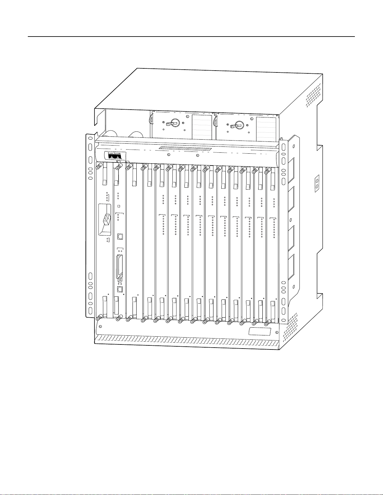
The Cisco 6200 consists of circuitry and connections that reside within a shelf or chassis that allows
modular insertion and removalof the various field-replaceable units (FRUs).The chassis consists of
a module compartment, a fan compartment, a power module compartment, a backplane, and I/O
cabling. Figure 1-1 shows the front of the chassis; Figure 1-2 shows the back.
1.2.1 Module Compartment
The module compartment holds all circuitry that relates to Cisco 6200 operation. The module
compartment includes 14 slots that hold the modules (cards):
• Slot 1: Holds the network trunk card (NTC).
• Slot 2: Holds the management processor card (MPC).
• Slots 3 and 4: Unoccupied in this release of the system.
• Slots 5 to 14: Hold up to ten subscriber line cards (SLCs).
All Cisco 6200 cards can be installed and removed while the rest of the system continues to operate.
(However, the system cannot pass data if the NTC is removed.) The NTC, MPC, and SLCs are
described later in this chapter.
Cisco 6200 User Guide1-2
Page 3
78-5296-02 10/02/98 Hardware Description 1
Figure 1-1 Cisco 6200 Chassis, Front View
O
POWER
READY
OC3-SM
SRVC
PROT
NTC
TD
RD
I
MPC
POWER
A
READY
C
T
I
ACTIVE
V
E
ACO
ALARMS
CRIT
MAJ
MIN
C
N
S
L
A
SLOT
0
1
POWER
SLC
SLC
SLC
SLC
8CAP
8CAP
8CAP
POWER
READY
PRIME
SEC
PORTS
0
1
2
3
4
5
6
7
POWER
READY
READY
PRIME
PRIME
SEC
SEC
PORTS
PORTS
0
0
1
1
2
2
3
3
4
4
5
5
6
6
7
7
POWER
SLC
8CAP
8CAP
POWER
READY
READY
PRIME
PRIME
SEC
SEC
PORTS
PORTS
0
0
1
1
2
2
3
3
4
4
5
5
6
6
7
7
POWER
O
I
SLC
SLC
SLC
SLC
8CAP
8CAP
8CAP
POWER
READY
PRIME
SEC
PORTS
0
1
2
3
4
5
6
7
POWER
READY
READY
PRIME
PRIME
SEC
SEC
PORTS
PORTS
0
0
1
1
2
2
3
3
4
4
5
5
6
6
7
7
POWER
SLC
8CAP
8CAP
POWER
READY
READY
PRIME
PRIME
SEC
SEC
PORTS
PORTS
0
0
1
1
2
2
3
3
4
4
5
5
6
6
7
7
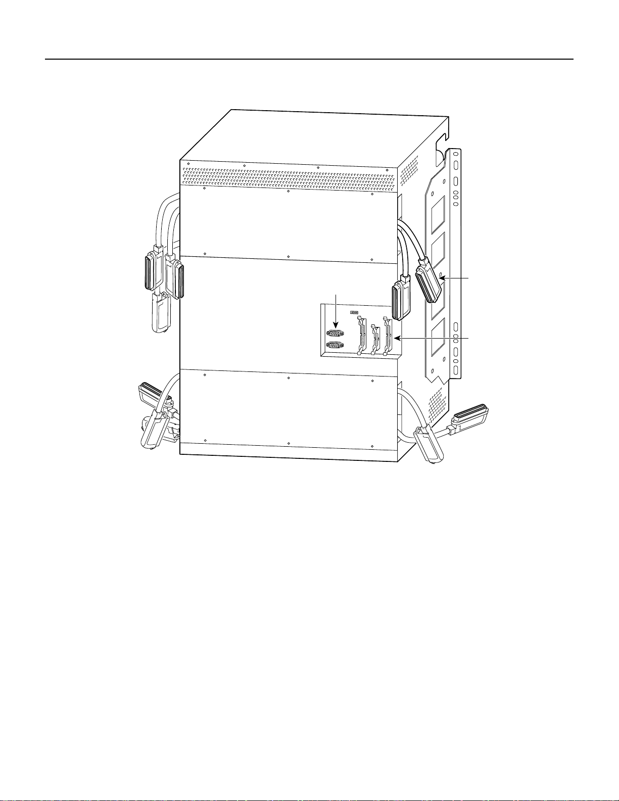
1.2.2 Backplane
Located behind the module compartment, the backplane provides the following services:
• Interconnects the MPC, NTC, and SLCs
• Connects the SLCs with the subscribers (local loops) or the POTS splitter
• Distributes power, clocking, and other common signals to all the modules
LINK
ACTV
E
N
E
T
12685
Cisco6200
SERIES
Cisco 6200 User Guide 1-3
Page 4
1 Hardware Description 78-5296-02 10/02/98
Figure 1-2 Cisco 6200 Chassis, Rear View
Dangler cables
Auxiliary port
connector
for subscriber
traffic
Alarm relay
connector
Primary (A) and Secondary (B) H-Buses
The backplane’s primary and secondary H-buses (horizontal buses) link the MPC, NTC, and SLCs.
In this release, the primary bus carries all traffic. The buses operate at 160 Mbps total throughput.
Each H-bus has two parts:
• A downstream component broadcasts all cells received from the NTC interface to each SLC.
(Logic on the SLC filters and directs cells destined for each port.)
• An upstream component provides a contention mechanism for cells received from subscriber
ports to be funneled into the upstream NTC path.
Ethernet Management Bus
A 10Base2-type Ethernet bus in the backplane carries internal management trafficbetween thecards.
12686
Cisco 6200 User Guide1-4
Page 5

78-5296-02 10/02/98 Hardware Description 1
Connections to POTS Splitters or Telephone Lines
On the inner surface of the backplane, the upper and lower SLC connectors connect the SLC in the
corresponding slot (5 to 14) with unshielded twisted pair (UTP) lines. These lines connect to an
external POTS splitter, and from there to subscribers over telephone lines. (If a subscriber is using a
telephone line for data only, the POTS splitter is not required.)
Ten factory-installed dangler cables provide DSL subscriber connections. Each dangler cable ends
with a 50-pin female Champ Telco connector (Figure 1-3), and each carries eight pairs to a single
SLC module. For a pinout list and an illustration showing the connectors on the rear panel, see
Appendix A, “Pin Assignments.”
Figure 1-3 Telco Champ Connector
11963
Alarm Relay Connection
Backplane connector J39, accessible from the rear of the chassis, is the alarm relay connector. The
alarm relays provide relay contact closures. The alarm relays transmit critical, major, and minor
alarmstoaseparate,externalalarmdevicewithin the CO. The alarm device uses a bell, light, or other
signal to alert CO support personnel of the change in status. (The alarm relay transmits audible and
visual alarms on separate circuits.) Alarms transmitted through J39 are also communicated by all of
the following methods:
• Alarm LEDs (labeled Critical, Major, and Minor) on the MPC. (Some alarms also affect the TD
and RD LEDs on the NTC.)
• Event messages on the console.
• Component status display of the Cisco 6200 Manager.
To turn off an audible alarm, do one of the following:
• Press the alarm cut-off (ACO) button on the MPC
• Click the ACO button in the Cisco 6200 Manager component status display
• Use the alarmcutoff command (at the console or via Telnet)
• Use a switch or command on your external alarm device
Cutting off an alarm has no effect on the alarm status of the system or on the indication of visual
alarms. Toclear analarm, you must correct thecondition that caused it. Toget information about the
source of an alarm, do one of the following:
• Use the Cisco 6200 Manager. (See the User Guide for the Cisco 6200 Manager for instructions.)
• Use the command show dsl alarms. (See Chapter7,“Troubleshooting,”formoreinformation on
this command.)
For a pinout list and additional information on connecting alarm relays, see Appendix A, “Pin
Assignments.”
Cisco 6200 User Guide 1-5
Page 6

1 Hardware Description 78-5296-02 10/02/98
Auxiliary Port
J40, a 9-pin female connector on the Cisco 6200 backplane, is an EIA/TIA-232 (RS-232) serial port
connecting to the management processor card (MPC). J40 is an auxiliary craft port that can be used
toconnect devicessuchasterminals,modems,orlaptopcomputerstothe Cisco 6200. It is accessible
from the rear of the chassis. For a pinout list, see Appendix A, “Pin Assignments.”
Power Terminals
J17, J18, J19, and J20, located at the upper right corner of the rear panel, are screw terminals for
–48 VDC power input and return:
• J17 is the –48V terminal for power circuit A.
• J19 is the +48V (return) terminal for power circuit A.
• J18 is the –48V terminal for power circuit B.
• J20 is the +48V (return) terminal for power circuit B.
Power circuit A is connected to the power entry module (PEM) on the left (as you face the front of
the chassis); power circuit B is connected to the PEM on the right.
Unused Connectors
The Cisco 6200 backplane contains several connectors and a jumper that are not used in the current
release. See Appendix A, “Pin Assignments,” for a list of the unused items.
1.2.3 Fan Tray
Thefantray,locatedatthebottom of the chassis, houses eight fansthatmaintain proper temperatures
inside the chassis, plus an air filter. The filter should be removed and cleaned periodically. Refer to
Chapter 6, “Preventive Maintenance,” for complete information on cleaning the air filter.
Caution The Cisco 6200 cooling fans must run continuously. The system may suffer thermal damage if the
fans stop for more than 10 minutes. (At ambient temperatures above 104 F(40 C),thermal damage may occur
sooner.)
1.2.4 Power Entry Modules (PEMs)
One or two PEMs distribute DC power to the chassis. The Cisco 6200 needs only one active PEM
to operate; if two PEMs are installed, the second PEM’s power source serves as a hot backup to the
first PEM’s power source.
Each PEM is connected to a single DC power source. For power redundancy, two PEMs must be
installed, and two separate DC powersources must be connected to the chassis. If one power source
is connected, only one PEM is required. There is no benefit to connecting two power sources to a
chassis with one PEM, or to installing two PEMs in a chassis with one power source.
The PEMs reside at the top of the Cisco 6200 chassis, and they are installed and accessed from the
front. DC power (–48V) enters the chassis through screw terminals on the rear panel of the chassis.
The PEMs receive power through the backplane and internal cabling.
The powerbayon the left is wired to power circuit A; the bay on the rightiswiredto powercircuit B.
(The circuits are identified at the power terminals on the backplane.)
Cisco 6200 User Guide1-6
Page 7
78-5296-02 10/02/98 Hardware Description 1
The following fixtures are present on the front panel of each PEM:
• A green LED that comes on to indicate that –48 VDC power is available to the chassis
• A circuit breaker
Note To turn off a Cisco 6200 that has two PEMs, you must flip the circuit breakers on both
PEMs to OFF (0).
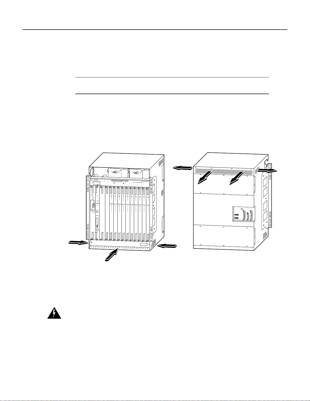
1.2.5 Cooling Vents
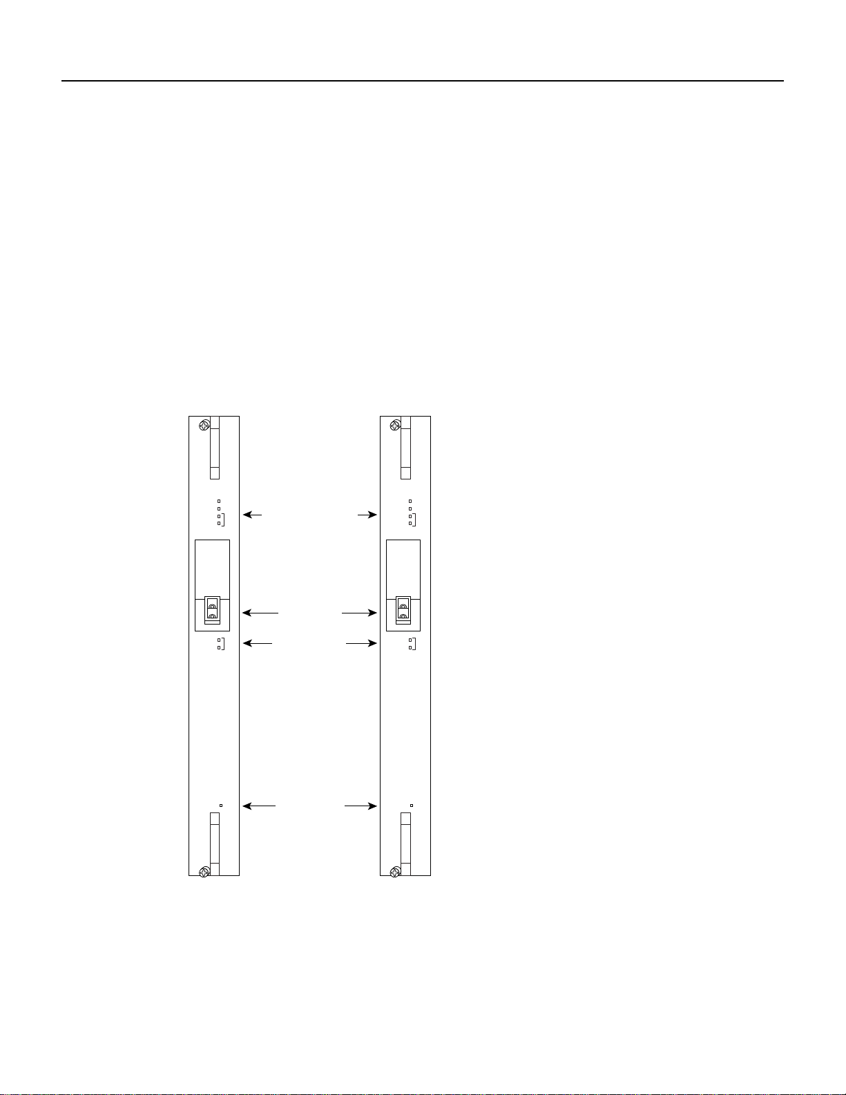
The cooling vents are located on the sides, front, and back of the Cisco 6200 chassis, as shown in
Figure 1-4. Air flows in at the bottom of the chassis, and flows out at the top. Do not obstruct the
intake and exhaust vents in any way.
Figure 1-4 Air Flow Through Intake and Exhaust Vents
1.2.6 DSLAM Specifications
Table 1-1 lists the specifications of the Cisco 6200 DSLAM. Table 1-2 lists standards and
certifications for the Cisco 6200 DSLAM.
Warning To prevent a Cisco 6200 system from overheating, do not operate it in an area that exceeds the
maximum recommended ambient temperature of 131˚F (55˚C).
12687
Cisco 6200 User Guide 1-7
Page 8

1 Hardware Description 78-5296-02 10/02/98
Table 1-1 Cisco 6200 DSLAM Specifications
Specification Description
Components 14-slot card compartment
Backplane
Fan compartment
Power module compartment
Power input Dual inputs, each –48 VDC
Tested voltages: –48V and –57V
Tolerance limits: –42V to –57V
Maximum input current: 23A
1
Power consumption, fully loaded
Dimensions Height: 23.6 in. (60.0 cm)
Weight with no cards
Weight fully loaded
2
1
Operating temperatures Short term: 23 to 131 F (–5 to 55 C)
Storage temperature –40 to 158 F (–40 to 70 C)
Operating humidity 15% to 90% noncondensing
Storage humidity 10% to 95% noncondensing
1 A fully loaded chassis has 1 fan tray, 2 PEMs, 1 MPC, 1 NTC, 10 SLCs, covers, and dangler cables.
2 A chassis with no cards has 1 fan tray, 2 power entry modules, covers, and dangler cables.
3 The chassis can operate safely at short term operating temperatures only if all of the fans are working properly. If a fan fails
in a chassis that is experiencing an ambient temperature above 104 F (40 C), thermal damage may occur.
With SLC 8CAPs: 820W
With SLC 8DMTs: 892W
Width: 17.5 in. (44.4 cm) (mounting brackets not included)
Depth: 11.8 in. (30.0 cm)
48 lb (21.7 kg)
82.5 lb (37.4 kg)
3
Long term: 32 to 104 F (0 to 40 C)
Table 1-2 Standards and Certifications
Category Description
NEBS Bellcore SR-3580 to Level 3 (GR-63, GR-1089)
EMI FCC Part 68 and part 15 Class A
CSA Class A
EN55022 Class A
AS/NRZ 3548 Class A
VCCI Class 1
Safety UL 1950
EN60950
CSA C22.2 No. 950
AUSTEL TS001
AS/NZS 3260
Immunity EN61000-4-2/IEC-1000-4-2
EN61000-4-3/IEC-1000-4-3
EN61000-4-4/IEC-1000-4-4
EN61000-4-5/IEC-1000-4-5
EN61000-4-6/IEC-1000-4-6
EN61000-4-11/IEC-1000-4-11
Cisco 6200 User Guide1-8
Page 9

78-5296-02 10/02/98 Hardware Description 1
1.3 Network Trunk Cards (NTCs)
This section describes the OC-3c andSTM-1 network trunk cards (NTCs). The NTCmodule resides
in slot 1 of the Cisco 6200 chassis.
1.3.1 What is the NTC OC-3?
The NTC is a service interface module that concentrates the data traffic from all Cisco 6200
subscriber ports and connects the node to a single trunk line from the service-providing ATM
network. This full-duplex channel unit carries data both downstream (to the subscriber) and
upstream (from the subscriber).
In Release 1, the trunk is a full-duplex OC-3c fiber optic channel. One OC-3c channel terminates at
a single NTC.
The OC3 NTC is available in both single-mode and multimode versions. Multimode fiber is
LED-driven and is designed for distances up to 2 kilometers (1.2 miles). Longer distances (up to
15 kilometers or 9.2 miles) require laser-driven single-mode fiber.
In the downstreamdirection, the OC3 NTC accepts ATMcells at the OC-3c rate (155.52 Mbps) and
adapts these cells to the Cisco 6200 internal bus.
The OC3 NTC also transmits upstream data back to the service provider via ATM on the OC-3c
physical layer.
The Cisco 6200 uses a fixed mapping of permanent virtual channels (PVCs) between trunk and
subscriber ports. This means that no configuration of thesecircuitsisrequired. Thirty-one PVCs link
each subscriber port to the trunk port on the NTC. These subscriber traffic PVCs are assigned virtual
channel identifiers (VCIs) 33 through 63. VCIs 0 through 31 are reserved for control traffic. All of
these VCs use virtual path identifier(VPI) 0. See the chapter “Command Reference” for instructions
on using the command show dsl vcmap to display the VCIs assigned to a particular slot or port.
The OC3 NTC collects ATM cell counts, which are accessible through the 6200 Management
Information Base (MIB). These cell count include:
• Number of nonidle cells transmitted upstream
• Number of nonidle downstream cells received with good or correctable header checksums
• Number of downstream cells received with uncorrectable header checksums
The OC3 NTC provides bidirectional adaptation between serial ATM cells within the OC-3c fiber
and the 16-bit-parallel format on the backplane’s 160-Mbps H-bus. Three basic circuitsperform this
adaptation process:
• Optical interface
• Upstream data transfer
• Downstream data transfer
Figure 1-5 shows how the three circuits interact.
Cisco 6200 User Guide 1-9
Page 10
1 Hardware Description 78-5296-02 10/02/98
Figure 1-5 NTC OC-3 Application
Cisco
6200
Line
module
12688
ATM on
OC-3c
NTC
Downstream
data
transfer
Optical
interface
Upstream
data
transfer
The optical interface performs the optical-to-electrical and electrical-to-optical conversions. Its
other tasks include clock recovery,overheadprocessing, celldelineation,anddiagnosticinformation
retrieval.
The upstream data transfer unit receives data via a 16-bit parallel input from the internal bus on the
node’s backplane. ATM cells are received from an SLC channel only after that channel has won
access to the upstream data bus from the other contending line channels. The upstream data transfer
unit monitors the contention bus to direct inbound data to the optical interface.
The downstream data transfer unit inserts data onto the bus. This circuit inserts idle cells when a full
data cell is not yet ready for transmission.
1.3.2 NTC OC-3: Physical Description
The NTC resides in slot 1 (the left-most slot as you face the front of the chassis). Each OC-3 NTC
faceplate is marked NTC OC3-SM (single-mode) or NTC OC3-MM (multimode). The faceplate
(see Figure 1-6) includes the fixtures discussed in the following paragraphs.
OC-3c Trunk Port
The dual SC connectors (one for transmitting, one for receiving) for the Cisco 6200 network trunk
port are recessed into the OC-3 NTC faceplate to prevent the cables from protruding too far outside
the faceplate.
Warning Class 1 laser product.
Warning Because invisible laser radiation may be emitted from the aperture of the port when no cable is
connected, avoid exposure to laser radiation and do not stare into open apertures.
Cisco 6200 User Guide1-10
Page 11
78-5296-02 10/02/98 Hardware Description 1
The fiber optic communication channels in the single-mode OC-3c card (NTC OC3-SM) operate
with laser energy,which can be harmful, especially to the eyes. Duringnormal operation this energy
is confined to the cable and presents no danger. To avoid injury when you are connecting or
disconnecting optical channels, observe these precautions:
• Always disconnect the card from the backplane before connecting or disconnecting optical
cables.
• Always keep the protective cap on the optic connector when the connector is not in use.
• Never look into an optical cable or connector.
Reset Switch
The reset switch is recessed behind the faceplate to avoid accidental disturbance. It is not for
customer use.
Figure 1-6 NTC OC-3 Faceplates
POWER
READY
PRIME
NTC
OC3-SM
SEC
TD
RD
A
C
T
I
V
E
A
Card status LEDs
OC-3c port
Transmit and
receive LEDs
Reset switch
POWER
READY
PRIME
NTC
OC3-MM
SEC
TD
RD
A
C
T
I
V
E
A
12689
LED Indicators
Table 1-3 describes the LEDs on the faceplate of the OC-3 NTC.
Cisco 6200 User Guide 1-11
Page 12

1 Hardware Description 78-5296-02 10/02/98
Table 1-3 LEDs on the NTC OC-3
LED Color Condition Indicated
POWER Green The module is receiving power.
READY Green
Yellow
Off
PRIME Green This NTC is active and is using the primary bus.
SEC Green This NTC is active and is using the secondary bus. (Redundant systems only.)
TD Green
Yellow
Red
RD Green
Yellow
Red
The NTC is experiencing no problems.
The NTC failed its power-on self test; it has a hardware problem. Refer to
Chapter 7, “Troubleshooting.”
The NTC is either initializing or in test mode.
None of the fault conditions that cause the LED to turn yellow or turn off have
been reported.
The LRFI fault condition has been reported on the transmit side.
The PRFI fault condition has been reported on the transmit side.
None of the fault conditions that cause the LED to turn yellow or turn off have
been reported.
One or more of the following fault conditions have been reported on the receive
side: LOS, LOF, LOP, EQF, LOCD, LAIS.
One or more of the following fault conditions have been reported on the receive
side: PAIS,LOST, Signal Label Mismatch. It is not possible to determine with a
high degree of certainty the operational state of the link when one of these
conditions is present.
Cisco 6200 User Guide1-12
Page 13

78-5296-02 10/02/98 Hardware Description 1
1.3.3 NTC OC-3 Specifications
Table 1-4 lists the physical and electrical specifications of the NTC.
Table 1-4 NTC OC-3 Specifications
Specification Description
External interface One SONET STS-3c (155 Mbps).
Single-mode (intermediate reach) and
multimode OC-3c versions available
Connector type SC
Fiber types • Single mode (up to 15 km)
• Multimode (up to 2 km)
Average transmitted power • Single mode: –11.5 dBm
• Multimode: –17 dBm
Average received power • Single mode: –28 to –8 dBm
• Multimode: –30 to –14 dBm
Transmission distances • Single mode: up to 15 km (9.2 miles)
• Multimode: up to 2 km (1.2 miles)
Wavelength (both modes) 1310 nm
Level 2 protocol ATM
Timing Loop timed
Internal interface 16-bit parallel bus at 10 Mbps (160 Mbps
total throughput)
Internal hardware • Motorola MC68360
• 0.5M of PROM
• 4M of RAM
• Odetics SONET interface
Dimensions
(width x height x depth)
Weight 2 lb (0.9 kg)
Power consumption 26W
1.5 x 15.75 x 9.75 in
(3.8 x 40.0 x 24.8 cm)
1.3.4 What is the NTC STM-1?
The NTC STM-1 is a service interface module that concentrates the data traffic from all Cisco 6200
subscriber ports and connects the node to a single trunk line from the service-providing ATM
network. This full-duplex channel unit carries data both downstream (to the subscriber) and
upstream (from the subscriber).
The trunk is a full-duplex STM-1 fiber optic channel. One STM-1 channel terminates at a single
NTC.
The NTC STM-1 is available in both single-mode and multimode versions. Multimode fiber is
LED-driven and is designed for distances up to 2 kilometers (1.2 miles). Longer distances (up to
15 kilometers or 9.2 miles) require laser-driven single-mode fiber.
In the downstream direction, the NTC STM-1 acceptsATM cellsat the SDH rate (155.52 Mbps)and
adapts these cells to the Cisco 6200 internal bus.
Cisco 6200 User Guide 1-13
Page 14
1 Hardware Description 78-5296-02 10/02/98
The NTC STM-1 also transmits upstream data back to the service provider via ATM on the STM-1
physical layer.
The Cisco 6200 uses a fixed mapping of permanent virtual channels (PVCs) between trunk and
subscriber ports. This means that no configuration of thesecircuitsisrequired. Thirty-one PVCs link
each subscriber port to the trunk port on the NTC. These subscriber traffic PVCs are assigned virtual
channel identifiers (VCIs) 33 through 63. VCIs 0 through 31 are reserved for control traffic. All of
these VCs use virtual path identifier (VPI) 0. See the Cisco 6200 User Guide for instructions on
using the command show dsl vcmap to display the VCIs assigned to a particular slot or port.
The NTC STM-1 collects ATM cell counts, which are accessible through the 6200 Management
Information Base (MIB). These cell count include:
• Number of nonidle cells transmitted upstream
• Number of nonidle downstream cells received with good or correctable header checksums
• Number of downstream cells received with uncorrectable header checksums
The NTC STM-1 providesbidirectionaladaptation between serial ATMcellswithintheSTM-1fiber
and the 16-bit-parallel format on the backplane’s 160-Mbps H-bus. Three basic circuitsperform this
adaptation process:
• Optical interface
• Upstream data transfer
• Downstream data transfer
Figure 1-7 shows how the three circuits interact.
Figure 1-7 NTC STM-1 Application
NTC
Downstream
data
transfer
ATM on
STM-1
Optical
interface
Upstream
data
transfer
Cisco
6200
Line
module
14270
The optical interface performs the optical-to-electrical and electrical-to-optical conversions. Its
other tasks include clock recovery, cell delineation, and diagnostic information retrieval.
Cisco 6200 User Guide1-14
Page 15

78-5296-02 10/02/98 Hardware Description 1
The upstream data transfer unit receives data via a 16-bit parallel input from the internal bus on the
node’sbackplane. ATMcells are received from a subscriber line card (SLC) channel only after that
channel has won access to the upstream data bus from the other contending line channels. The
upstreamdatatransferunitmonitorsthecontentionbusto direct inbound data to the optical interface.
The downstream data transfer unit inserts data onto the bus. This circuit inserts idle cells when a full
data cell is not yet ready for transmission.
1.3.5 NTC STM-1: Physical Description
The NTC resides in slot 1 (the left-most slot as you face the front of the chassis). Each NTC STM-1
faceplateismarkedNTC STM1-SM (single-mode) or NTC STM1-MM (multimode). The faceplates
(see Figure 1-8) include the fixtures discussed in the following paragraphs.
Trunk Port
The dual SC connectors (one for transmitting, one for receiving) for the Cisco 6200 network trunk
port are recessed into the NTC faceplate to prevent the cables from protruding too far outside the
faceplate.
Warning Class 1 laser product.
Warning Because invisible laser radiation may be emitted from the aperture of the port when no cable is
connected, avoid exposure to laser radiation and do not stare into open apertures.
The fiber optic communication channels in the single-mode trunk card (NTC STM1-SM) operate
with laser energy,which can be harmful, especially to the eyes. Duringnormal operation this energy
is confined to the cable and presents no danger. To avoid injury when you are connecting or
disconnecting optical channels, observe these precautions:
• Always disconnect the card from the backplane before connecting or disconnecting optical
cables.
• Always keep the protective cap on the optic connector when the connector is not in use.
• Never look into an optical cable or connector.
Reset Switch
The reset switch is recessed behind the faceplate to avoid accidental disturbance. It is not for
customer use.
Cisco 6200 User Guide 1-15
Page 16

1 Hardware Description 78-5296-02 10/02/98
Figure 1-8 NTC STM-1 Faceplates
NTC
STM1-SM
POWER
READY
PRIME
SEC
TD
RD
A
C
T
I
V
E
A
Card status LEDs
STM-1 port
Transmit and
receive LEDs
Reset switch
NTC
STM1-MM
POWER
READY
PRIME
SEC
TD
RD
A
C
T
I
V
E
A
14271
LED Indicators
Table 1-5 describes the LEDs on the faceplate of the NTC STM-1.
Cisco 6200 User Guide1-16
Page 17

78-5296-02 10/02/98 Hardware Description 1
Table 1-5 LEDs on the NTC STM-1
LED Color Condition Indicated
POWER Green The module is receiving power.
READY Green
Yellow
Off
PRIME Green This NTC is active and is using the primary bus.
SEC Green This NTC is active and is using the secondary bus. (Redundant systems only.)
TD Green
Yellow
RD Green
Yellow
The NTC is experiencing no problems.
The NTC failed its power-on self test; it has a hardware problem. Refer to the
Cisco 6200 User Guide for troubleshooting instructions.
The NTC is either initializing or in test mode.
None of the fault conditions that cause the LED to turn yellow or turn off have
been reported.
The LRFI fault condition has been reported on the transmit side.
None of the fault conditions that cause the LED to turn yellow or turn off have
been reported.
One or more of the following fault conditions have been reported on the receive
side: LOS, LOF, LOP, EQF, LOCD, LAIS.
1.3.6 NTC STM-1 Specifications
Table 1-6 lists the physical and electrical specifications of the NTC STM-1.
Cisco 6200 User Guide 1-17
Page 18

1 Hardware Description 78-5296-02 10/02/98
Table 1-6 NTC STM-1 Specifications
Specification Description
External interface One SDH STM-1 (155 Mbps). Single-mode
(intermediate reach) and multimode STM-1
versions available
Connector type SC
Fiber types • Single mode (up to 15 km)
• Multimode (up to 2 km)
Average transmitted power • Single mode: –11.5 dBm
• Multimode: –17 dBm
Average received power • Single mode: –28 to –8 dBm
• Multimode: –30 to –14 dBm
Transmission distances • Single mode: up to 15 km (9.2 miles)
• Multimode: up to 2 km (1.2 miles)
Wavelength (both modes) 1310 nm
Level 2 protocol ATM
Timing Loop timed
Internal interface 16-bit parallel bus at 10 Mbps (160 Mbps
total throughput)
Internal hardware • Motorola MC68360
• 0.5M of PROM
• 4M of RAM
• Odetics SDH interface
Dimensions
(width x height x depth)
Weight 2 lb (0.9 kg)
Power consumption 26W
1.5 x 15.75 x 9.75 in
(3.8 x 40.0 x 24.8 cm)
1.4 Management Processor Card (MPC)
The Cisco 6200 is controlled and managed by the MPC.
1.4.1 Functional Description
The MPC performs management and storage tasks for the Cisco 6200 DSLAM. The MPC provides
• The Cisco IOS command line interface (CLI) for configuration and monitoring
• An SNMP agent for communicating between the Cisco 6200 and the PC running the Cisco 6200
Manager software
• Alarm contacts and environmental monitoring of key system resources
• Line card configuration and fault polling
• Nonvolatile storage of configuration information
• Two PCMCIA Flash slots for storage of software images and configuration data
Cisco 6200 User Guide1-18
Page 19

78-5296-02 10/02/98 Hardware Description 1
The MPC runs a version of Cisco IOS software that is designed for DSL multiplexing.
At startup, the MPC loads program software and configuration datafrom NVRAM, from a serveron
the network, or from a Flash card in one of its PCMCIA slots. The MPC then provides boot images
to the line cards. After initializing the system, the MPC provides monitoring and control services,
including the CLI (available at the console and via Telnet); SNMP communication with the Cisco
6200 Manager; and critical, major, and minor alarm signals.
1.4.2 Physical Description
The MPC resides inslot 2. The MPC faceplate (see Figure 1-9) includes the fixtures discussed in the
following paragraphs.
Figure 1-9 MPC Faceplate
MPC
POWER
ALARMS
READY
ACTIVE
CRIT
MAJ
MIN
Card status LEDs
ACO
Alarm cut-off switch
Alarm LEDs
C
N
S
Console port
L
SLOT
0 1
Two PCMCIA slots
PCMCIA ejection buttons
LINK
ACTV
E
N
Ethernet port
E
T
Reset switch
11948
ACO Switch
The alarm cut-off (ACO) switch is a pushbutton located near the top of the MPC. Press the switch
to turn off an audible alarm. (For more information on alarms, see the “Alarm Relay Connection”
section on page 1-5.)
Cisco 6200 User Guide 1-19
Page 20

1 Hardware Description 78-5296-02 10/02/98
Console Port
The console port on the MPC is a serial EIA/TIA-232 port with an RJ-45 connector. See Appendix
A, “Pin Assignments,” for pinouts.
PCMCIA Slots and Ejection Buttons
The MPC provides two slots for PCMCIA Flash memory cards. PCMCIA cards store system
software and node configuration information. An ejection button is located beneath each PCMCIA
slot; push the button to remove the card.
Ethernet Port
The Ethernet port on the MPC is a 10BaseT port with an RJ-45 connector. It is used to connect the
Cisco 6200 to its management station. See Appendix A, “Pin Assignments,” for pinouts.
Reset Switch
The reset switch, which initializes the MPC, is recessed behind the faceplate to avoid accidental
disturbance.
LED Indicators
All LEDs on the MPC are described in Table 1-7.
Table 1-7 MPC LEDs
LED Color Condition Indicated
POWER Green The MPC is receiving power.
READY Green
Yellow
Off
ACTIVE Green This MPC is active.
CRITICAL Red The system is experiencing a critical alarm. A critical alarm affects many or all
MAJOR Red The system is experiencing a major alarm. A major alarm affects several
MINOR Yellow The system is experiencing a minor alarm. A minor alarm affects a small
Slot 0 Green PCMCIA card slot 0 is being accessed by system software.
Slot 1 Green PCMCIA card slot 1 is being accessed by system software.
ACT Green The Ethernet port is receiving or transmitting data (active).
LNK Green A 10BaseT link is present on the Ethernet port.
The MPC is experiencing no problems.
The MPC failed its power-on self test—it has a hardware problem. Refer to
Chapter 7, “Troubleshooting.”
The MPC is either initializing or in test mode.
of the subscribers connected to the node. (Failure of the NTC or the trunk can
cause a critical alarm.) Use the Cisco 6200 Manager or the command line
interface to identify the problem.
subscribers. (A total SLC failure, which affects all of the subscribers connected
to that card, causes a major alarm.) Use the Cisco 6200 Manager or the
command line interface to identify the problem.
number of subscribers. (A partial SLC failure causes a minor alarm.) Use the
Cisco 6200 Manager or the command line interface to identify the problem.
Cisco 6200 User Guide1-20
Page 21

78-5296-02 10/02/98 Hardware Description 1
1.4.3 MPC Specifications
Table 1-8 lists the physical and electrical specifications of the MPC.
Table 1-8 MPC Specifications
Specification Description
External Interfaces • EIA/TIA-232 console port
• 10BaseT Ethernet management port
Internal Hardware • MIPS RV4640 processor
• Galileo GT64011 memory management unit
• 16 MB of DRAM
• 8MB of Flash memory (to store boot image)
• 2 PCMCIA Flash card slots
Dimensions
(width x height x depth)
Weight 2.5 lb (1.13 kg)
Power consumption 36.5W
1.5 x 15.75 x 9.75 in
(3.8 x 40.0 x 24.8 cm)
Cisco 6200 User Guide 1-21
Page 22

1 Hardware Description 78-5296-02 10/02/98
1.5 Subscriber Line Card (SLC)
This section describes the CAP and DMT versions of the subscriber line card (SLC). A Cisco 6200
chassis can hold up to 10 SLC modules.
Note All the SLCs in a Cisco 6200 chassis should be of the same type. The mixture of CAP and
DMT cards in a single chassis is not supported.
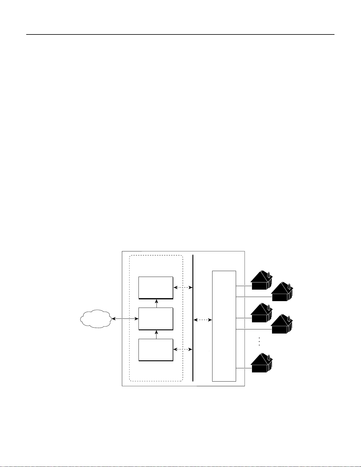
1.5.1 What is the SLC 8CAP?
The CAP version of theSLC (labeled SLC 8CAP) is a hot-swappable line modulethat provides data
communication between the Cisco 6200 node and up to eightsubscribers. Modems on the CAP SLC
use the carrierless amplitude modulation/phase modulation (CAP) method, a common line code
method for asymmetric digital subscriber line (ADSL) transmissions. As an ADSL device,the CAP
SLC transmits high-speed data through an external plain old telephone service (POTS) splitter to
subscribers over existing, telephone-grade segments of copper wire. Figure 1-10 illustrates SLC
operation.
The CAP SLC transports data at speeds up to 7 Mbps downstream (from the service provider to the
subscriber) and receives up to 1 Mbps upstream (from the subscriber to the service provider). The
SLC supports upstream and downstream passband channels for subscriber data. Baseband POTS is
unused by the SLC; data is added to this channel by the external POTS splitter.
How the SLC Handles Traffic
In the downstream direction, the SLC receives ATM cells from the Cisco 6200 backplane bus. The
cell filter discards cells whose virtual path/virtual channel IDs (VPI/VCIs) do not pertain to this
subscriber’schannel. (Each port has afixed set of 31 VCIs, which are permanently assigned to VCIs
on the NTC.) The traffic controller buffers cells. Then the CAP transceiver transmits the outbound
cells. The SLC sends the cells out to an externalPOTSsplitter,which inserts baseband POTS traffic
(if any such traffic is provided) before sending the downstream ADSL and POTS signals across
standard unshielded twisted pair copper wire to the subscriber.
In the upstream direction, the SLCreceivesADSL signalsfrom a POTSsplitter and demodulates the
CAP-modulated signal. Then the SLC channel contends with the other SLC channels for the
upstream data bus. Two priority levels are available. For the first Cisco 6200 release, only UBR
service is available. The SLC will ensure fair access among all cells of the same priority.
The SLC separates the upstream and downstream data channels:
• The upstream data channel occupies a band between 30 kHz and 200 kHz.
• The downstream data channel takes the band between 240 kHz and 1.5 MHz.
At the subscriber site, the DSL customer premises equipment (the Cisco 675, for example)
demodulates the downstream signal and sends the data to the subscriber’s PC.
Transmission Rates and Modem Training
Two options are available with respect to transmission rates:
• You can set the subscriber ports to rate-adapt (train) automatically to the highest attainable line
speed.
• You can set transmission speeds. Upstream and downstream speeds can be set separately.
Cisco 6200 User Guide1-22
Page 23

78-5296-02 10/02/98 Hardware Description 1
In the downstream direction, 11 rates are available ranging from 640 kbps to 7.168 Mbps. In the
upstream direction, 9 rates are available, ranging from 91 kbps to 1.088 Mbps.
The modems on the CAP SLC train in sequence, first downstream, then upstream. Each modem first
acquires the line. Then it tests the signal quality on the line by measuring the signal-to-noise ratio
(SNR). It adds a preset margin, 6 dbm, to the SNR, and compares the resulting value to a table. If
the value is acceptable, the modem trains at the configured rate. If not, the modem repeats the
process, using the next lower transmission rate. The modem keeps trying to train indefinitely until it
is successful.
Statistics
The SLC gathers signal quality statistics for network management purposes. It sends this
information to the management system via the master SNMP agent. The SLC reports each of the
following statistics to the management system for both upstream and downstream traffic:
• Number of nonidle cells transmitted downstream
• Number of nonidle upstream cells received with valid header checksum
• Number of upstream cells received with invalid header checksum
• Number of errored seconds (this is the number of seconds inwhich at least one header checksum
error or loss of cell delineation is observed), both upstream and downstream
Figure 1-10 SLC 8CAP Operation
Cell
filter
Contention
and
arbitration
ATM
NTC
Cisco
6200
CAP
transceiver
SLC
Port 1
Port 2
Port 3
Port 8
Public
telephone
network
ADSL
modem
POTS
splitter
POTS
splitter
12690
Cisco 6200 User Guide 1-23
Page 24

1 Hardware Description 78-5296-02 10/02/98
1.5.2 SLC 8CAP: Physical Description
Up to 10 SLCs can be installed in a Cisco 6200 cabinet. The cabinet slots assigned to the SLCs are
slot 5 through slot 14.
The CAP SLC’s faceplate is labeled SCL 8CAP. The faceplate (Figure 1-11) includes the fixtures
discussed in the following paragraphs.
Reset Switch
The reset switch is recessed behind the faceplate to avoidaccidental activation.It is not for customer
use.
LED Indicators
Table 1-9 describes the LEDs on the faceplate of the SLC.
Figure 1-11 SLC 8CAP Faceplate
POWER
READY
PRIME
SLC
8CAP
SEC
PORTS
0
1
2
3
4
5
6
7
Card status LEDs
Port status LEDs
Reset switch
11947
Cisco 6200 User Guide1-24
Page 25

78-5296-02 10/02/98 Hardware Description 1
Table 1-9 SLC 8CAP LEDs
LED Color Condition Indicated
POWER Green The SLC is receiving power.
READY Green
Yellow
Off
PRIME Green The SLC is using the primary (A) bus to move information across the backplane.
SEC Green The SLC is using the secondary (B) bus to move information across the backplane.
Ports 0 to 7 Green The following conditions exist:
Flashing
green
Off One of the following conditions exists:
The SLC is experiencing no problems.
At least one port on the SLC is in line test mode.
The SLC is not communicating with the MPC. This is the case when
• The SLC is initializing.
• The SLC has a hardware problem. If the READY LED is off for an extended
period when the POWER LED is on, see the Cisco 6200 User Guide for
instructions on troubleshooting the SLC.
(Redundant systems only.)
• The port is receiving the upstream heartbeat message regularly.
• The heartbeat message indicates the CAP PIM has HEC alignment in the
downstream direction.
• The SLC has HEC alignment in the upstream direction.
• The modems on both sides have negotiated the loop rates.
The port LEDs remain lit (green) in the presence of occasional minor alarms.
The loop is rate-adapting (training).
• The port is experiencing an intrusive line quality test.
• The port is experiencing an intrusive CAP hardware test.
• The port is disabled or is not configured.
Cisco 6200 User Guide 1-25
Page 26

1 Hardware Description 78-5296-02 10/02/98
1.5.3 SLC 8CAP Specifications
Table 1-10 lists the physical and electrical specifications of the CAP SLC (SLC 8CAP).
Table 1-10 SLC 8CAP Specifications
Specification Description
Subscriber ports 8 per card
Transmission speeds Downstream: up to 7 Mbps
Upstream: up to 1 Mbps
Loop hardware media Unshielded twisted pair copper wire
Loop modulation method ADSL with CAP line code
Layer 2 format ATM (service and subscriber side, end-to-end)
ATM virtual circuits supported Up to 31 per subscriber, numbered 33 through 63 (VPI 0)
Data channel frequencies • Upstream: 30 to 200 kHz
• Downstream: 240 kHz to 1.5 MHz
Internal hardware • Motorola MC68360
• 1 Mbyte Flash memory
• 512 kbyte Flash boot memory
• Globespan CAP chip set
• Cisco ATM framer
Dimensions
(width x height x depth)
Weight 3 lb (1.36 kg)
Power consumption 72W
1.17 x 15.75 x 9.75 in
(3.0 x 40.0 x 24.8 cm)
Cisco 6200 User Guide1-26
Page 27

78-5296-02 10/02/98 Hardware Description 1
1.5.4 What is the SLC 8DMT?
The eight-port DMT version of the SLC (SLC 8DMT) is a hot-swappable line module that provides
data communication between the Cisco 6200 node and up to eight subscribers. Modems on the SLC
8DMT use discrete multitone (DMT) modulation, a common method for encoding asymmetric
digital subscriber line (ADSL) transmissions.The SLC 8DMT transmits high-speeddata through an
externalPOTSsplitter to subscribersoverexisting, telephone-grade segments of copperwire.Figure
1-12 illustrates SLC operation.
Figure 1-12 SLC 8DMT Operation
Public
telephone
network
SLC
Port 1
Port 2
Port 3
Port 8
ADSL
modem
POTS
splitter
POTS
splitter
13068
ATM
NTC
Cisco
6200
Cell
filter
Contention
and
arbitration
DMT
transceiver
The SLC 8DMT transports data at speeds up to 8 Mbps downstream (from the service provider to
the subscriber) and receives at speeds up to 800 kbps upstream (from the subscriber to the service
provider). The SLC supports upstream and downstream passband channels for subscriber data.
Baseband plain old telephone service (POTS) is unused by the SLC; voiceand data are added by the
external POTS splitter.
How the SLC 8DMT Handles Traffic
In the downstream direction, the SLC receives ATM cells from the Cisco 6200 backplane bus. The
cell filter discards cells whose virtual path/virtual channel IDs (VPI/VCIs) do not pertain to a
particular subscriber’s channel. (Each port has a fixed set of 31 VCIs, numbered 33 to 63, which are
permanently assigned to VCIs on the NTC.) The cell filter buffers cells, and the DMT transceiver
transmits the outbound cells. The SLC sends the cells out to an external POTSsplitter, which inserts
baseband POTS traffic (if any such traffic is provided) before sending the downstream ADSL and
POTS signals across standard unshielded twisted pair copper wire to the subscriber.
Cisco 6200 User Guide 1-27
Page 28

1 Hardware Description 78-5296-02 10/02/98
In the upstream direction, the SLCreceivesADSL signalsfrom a POTSsplitter and demodulates the
DMT-modulated signal. Then the SLC channel contends with the other SLC channels for the
upstream data bus. Two priority levels are available. For the first Cisco 6200 release, only UBR
service is available. The SLC will ensure fair access among all cells of the same priority.
The SLC separates the upstream and downstream data channels:
• The upstream data channel occupies a band between 25.875 kHz and 138 kHz.
• The downstream data channel takes the band between 138 kHz and 1.104 MHz.
At the subscriber site, the DSL customer premises equipment (CPE)—the Cisco 676, for example—
demodulates the downstream signal and sends the data to the subscriber’s PC.
Transmission Rates and Modem Training
Two modes are available for setting transmission rates:
• Rate-adaptivemode: Youcan set the subscriber portsto adapt (train) automatically to the highest
line speed attainable for the configured signal-to-noise ratio (SNR) margin for each direction.
• Explicit rate mode: You can set SNR margins and transmission speeds explicitly. Upstream and
downstream speeds can be set separately.
Statistics
You can mix rate-adaptive and explicit modes on the same circuit, using one mode for upstream
traffic and the other for downstream traffic.
Rates available for downstream traffic range from 32 kbps to 8.032 Mbps, in increments of 32 kb
(32 kbps,64 kbps, 96 kbps, 128 kbps, and so on). Rates availableforupstreamtrafficstart at 32 kbps
and increase in 32-kb increments to a maximum upstream rate of 864 kbps.
The modems on the SLC 8DMT train simultaneously in the upstream and downstream directions.
Each modem first tries to train at the configured rate at a specified SNR margin. If the first attempt
fails in either direction butaCPE is detected, the modem tries to train at the highest rate possible (up
to the configured rate). The modem keeps trying to train until it is successful.
The SLC 8DMT gathers signal quality statistics for network management purposes and sends this
information to the management system via SNMP. The SLC reports each of the following statistics
to the management system for both upstream and downstream traffic:
• Near and far end uncorrected blocks
• Near and far end corrected blocks
• Near and far end loss of signal (LOS) counter
• Near end loss of frame (LOF) counter
• Remote failure indication (RFI, or far end LOF)
• Near and far end errored seconds
• Near and far end attenuation
• Near and far end SNR margin
• Upstream and downstream actual rates
• Number of nonidle cells transmitted downstream
• Number of nonidle upstream cells received with valid header checksum
Cisco 6200 User Guide1-28
Page 29

78-5296-02 10/02/98 Hardware Description 1
• Number of upstream cells received with invalid header checksum
• Number of errored seconds (this is the number of seconds in which at least one DMT-layer CRC
error, loss of signal, or severely errored frame is observed), both upstream and downstream
In addition, the SLC 8DMT reports the following fault indications:
• Far end LPR
• Near end LOS
• Near end LOF
• Near end loss of cell delineation (LOCD)
1.5.5 SLC 8DMT: Physical Description
Up to ten SLCs can be installed in a Cisco 6200 cabinet. The slots assigned to the SLCs are slot 5
through slot 14.
The card’s faceplate is labeled SLC 8DMT. The faceplate (Figure 1-13) includes a reset switch and
LED indicators.
Cisco 6200 User Guide 1-29
Page 30

1 Hardware Description 78-5296-02 10/02/98
Figure 1-13 SLC 8DMT Faceplate
SLC
8DMT
POWER
READY
PRIME
SEC
PORTS
0
1
2
3
4
5
6
7
Card status LEDs
Port status LEDs
Reset switch
13067
Reset Switch
The reset switch is recessed behind the faceplate to avoidaccidental activation.It is not for customer
use.
LED Indicators
Table 1-11 describes the LEDs on the faceplate of the SLC.
Cisco 6200 User Guide1-30
Page 31

78-5296-02 10/02/98 Hardware Description 1
Table 1-11 SLC 8DMT LEDs
LED Color Condition Indicated
POWER Green The SLC is receiving power.
READY Green
Yellow
Off
PRIME Green The SLC is using the primary (A) bus to move information across the backplane.
SEC Green The SLC is using the secondary (B) bus to move information across the backplane.
Ports 0 to 7 Green The following conditions exist:
Flashing
green
Off One of the following conditions exists:
The SLC is experiencing no problems.
At least one port on the SLC is in line test mode.
The SLC is not communicating with the MPC. This is the case when
• The SLC is initializing.
• The SLC has a hardware problem. If the READY LED is off for an extended
period when the POWER LED is on, see the Cisco 6200 User Guide for
instructions on troubleshooting the SLC.
(Redundant systems only.)
• The port is receiving good signal levels (no loss of signal, or LOS) from the CPE.
• The port has frame alignment with the far end CPE (no loss of frame (LOF) or
severely errored frames (SEC)).
• The SLC has HEC alignment in the upstream direction.
• The modems on both sides have negotiated the loop rates.
The port LEDs remain lit (green) in the presence of occasional minor alarms.
The port is enabled and is trying to communicate with the remote CPE. (That is, the
port is training or preparing to train.)
• The port is experiencing an intrusive DMT hardware test.
• The port is disabled or is not configured.
Cisco 6200 User Guide 1-31
Page 32

1 Hardware Description 78-5296-02 10/02/98
1.5.6 SLC 8DMT Specifications
Table 1-12 lists the physical and electrical specifications of the SLC 8DMT.
Table 1-12 SLC 8DMT Specifications
Specification Description
Subscriber ports 8 per card
Transmission speeds Downstream: up to 8.032 Mbps
Upstream: up to 864 kbps
Loop hardware media Unshielded twisted pair copper wire
Loop modulation method ADSL with DMT line code
Layer 2 format ATM (service and subscriber side, end-to-end)
ATM virtual circuits supported Up to 31 per subscriber, numbered 33 through 63 (VPI 0)
Data channel frequencies • Upstream: 25.875 to 138 kHz
• Downstream: 138 kHz to 1.104 MHz
Internal hardware • Motorola MC68360
• 1 Mbyte Flash memory
• 512 kbyte Flash boot memory
• ADI DMT chip set
• Cisco ATM framer
Dimensions
(width x height x depth)
Weight 3 lb (1.36 kg)
Power consumption 79.2 W
1.17 x 15.75 x 9.75 in
(3.0 x 40.0 x 24.8 cm)
Cisco 6200 User Guide1-32
 Loading...