

Page 1

CHAPTER
Cisco 6130 NI-2 DSLAM System
Cables
This chapter provides cabling guidelines, including
• NEBS Compliance Cabling Guidelines
• Required Cables for Installation with POTS Splitter
• Required Cables for Installation without POTS Splitter
• Required Cables for Subtended Network Configuration
Only qualified personnel should install, replace, or service this equipment.
3
For detailed port mapping tables, see Appendix B, “Port Mapping.” This appendix includes port
mapping tables that can be used for building Cisco 6130 NI-2 DSLAM cables.
Table 3-1 lists Cisco cables required for Cisco 6130 NI-2 system configurations with and without a
POTS splitter.
Table 3-1 Installation Cable Requirements for Cisco 6130 NI-2 DSLAM with and without a POTS Splitter
Configuration Connection Cable Type
Installation with
a POTS splitter
Installation
without a POTS
splitter
1 Six cables required.
2 Two cables required: 1 left and 1 right.
Siecor POTS
splitter to
DSLAM
DSLAM to
main
distribution
frame (MDF)
One-to-one
Three-to-three
Ports
POTS
DSLAM
1
128 128 DMT-2 (ADSL) Table 3-2 Figure 3-2
2
128 None DMT-2 (ADSL) Table 3-3 Figure 3-3 and
Splitter Table Figure
Line Coding
Technology
Reference
Figure 3-4
Cisco 6130 DSLAM with NI-2 User Guide 3-1
Page 2
3 Cisco 6130 NI-2 DSLAM System Cables 78-10280-01 02/15/00
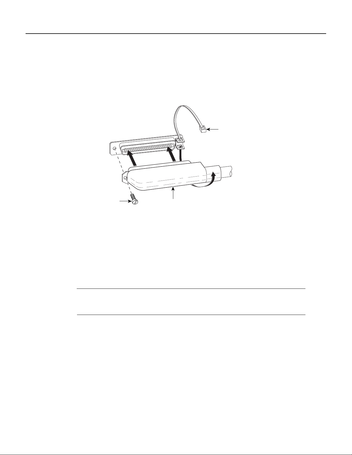
3.1 NEBS Compliance Cabling Guidelines
To comply with NEBS requirements, ensure that all cables are screw fastened onto backplane
receptacles and that the cable Champ connectors are tie wrapped (Figure 3-1).
Figure 3-1 NEBS Cabling Compliance
Tie wrap
17092
Champ connector
screw
Champ
connector
3.2 Required Cables for Installation with POTS Splitter
During an installation with a POTS splitter, use only the Cisco cables specified in Table 3-1 to
connect the Cisco 6130 NI-2 DSLAM, the POTS splitter, and the CO facility MDF. This section
provides tables and illustrations for DSLAM-to-POTS splitter cable connections. Consult Siecor
documentation for line connections from the MDF to the POTS splitter and POTS splitter cabling
from the POTS splitter to the MDF.
Note SomeCisco6130 NI-2DSLAM receptaclesinthe cablingdiagrams arenotused because they
are specific to one of the other Cisco 6100 DSLAM system configurations or because they are
reserved for future use.
3.2.1 Making DSLAM-to-POTS Splitter Cable Connections
To connect the Cisco 6130 multiplexer chassis (MC) to the POTS splitter in installations with a
POTS splitter, use one-to-one Cisco Champ cables. Use one-to-one cables to connect the POTS
splitter xDSL outputs to the Cisco 6130 NI-2 multiplexerchassis ADSL inputs for DSLAM systems
with quad-port DMT-2 ATUC-1-4DMT modules.
Table 3-2 lists the backplane connectors and part number for the Cisco one-to-one cable kit that
permits you to connect the POTS splitter to the chassis (Cisco 6130 NI-2 DSLAM) backplane
receptacles in installations with a POTS splitter.
Cisco 6130 DSLAM with NI-2 User Guide3-2
Page 3

78-10280-01 02/15/00 Cisco 6130 NI-2 DSLAM System Cables 3
Table 3-2 1-to-1 Cable Connectors and Cable Part Number—DSLAM to POTS Splitter
Connections
Connectors Cisco Cable Part Number
DSLAM POTS Splitter Kit Subassembly
J39 xDSL 9-32 CAB-61-014 72-1665-01
J40 xDSL 1-8, 65-72
J41 xDSL 73-96
J42 xDSL 33-56
J43 xDSL 57-64, 121-128
J44 xDSL 97-120
Note When you use one-to-one cables, see Table B-1 through Table B-7 for port mapping
information.
Figure 3-2 shows one-to-one cabling between the chassis and the POTSsplitter.Use the cables listed
in Table 3-2 to make these connections.
Cisco 6130 DSLAM with NI-2 User Guide
3-3
Page 4

3 Cisco 6130 NI-2 DSLAM System Cables 78-10280-01 02/15/00
Figure 3-2 DSLAM to POTS Splitter Chassis Cabling Diagram (1-to-1 Cables)
MODEM
-48V_B
-48RTN
-48V_A
-48RTN
POOL
A
J48
OUT
P13
J39
P1
P2
P3
P4
P5
J47
J40
J41
RTN
RTN
-48VB
Cisco 6130
chassis
Fan
tray
J43
J42
P17
P14
P15
CRIT
CRIT
CRIT
MAJ
MAJ
MAJ
MIN
MIN
MIN
FAN
ACO
ACO
ALARM
E2A
VISUAL AUDIBLE
J46
MODEM
POOL
B
OUT
J49
ANALOG TEST I/F
RING
TIP
J44
P18
J1
+
P2
FAN
P2
-48VA
J1
POTS
splitter
3.3 Required Cables for Installation without POTS Splitter
In an installation without a POTS splitter, use only designated cables to connect the Cisco 6130 NI-2
DSLAM and the CO facility MDF. The illustrations in this section show you how to connect
three-to-three cables.
Note Some chassis connectors in the cabling diagrams are not used because they are specific to a
different Cisco 6100 series NI-2 DSLAM system or because they are reserved for future use.
3.3.1 Using Three-to-Three Cables
Toassociate the CO facility MDF wire pairs and the DSLAM modem ports, the three-to-three cables
remap wire pairs from the Cisco 6130 NI-2 DSLAM Champ connectors to the CO facility MDF
Champ receptacles.
28842
Cisco 6130 DSLAM with NI-2 User Guide3-4
Page 5

78-10280-01 02/15/00 Cisco 6130 NI-2 DSLAM System Cables 3
Use these cables in systems having quad-port ATUC-1-4DMT modules installed in the chassis.
Table 3-3 lists the Cisco 6130 NI-2 DSLAM backplane receptacles and the cable kit part number for
three-to-three Champ cable connectors between the DSLAM and the CO facility MDF in an
installation without a POTS splitter.
Table 3-3 Cisco Connectors and Part Number for 3-to-3 Cable Kit—DSLAM to MDF
Connections
Connector Cisco Part Number
DSLAM Main Distribution Frame Kit Subassembly
J39, J40, J41 P4 (slots 1 to 6),
P5 (slots 7, 8, and 21 to 24),
or P6 (slots 25 to 28)
J42, J43, J44 P1 (slots 13 to 18),
P2 (slots 19, 20, and 31 to 34),
or P3 (slots 35 to 38)
Note When you use a three-to-three cable kit, see Table B-8 on page B-10 for port mapping
CAB-DSLAM 128-MDF 72-1765-01
(right cable)
72-1720-01
(left cable)
information. Figure 3-3 shows the three-to-three cables.
Figure 3-3 Cisco 3-to-3 Cables
Left cable
P3
Slots 35 to 38
P2
Slots 19, 20, 31 to 34
P1
Slots 13 to 18
Right cable
P6
Slots 25 to 28
P5
Slots 7, 8, 21 to 24
P4
Slots 1 to 6
J44
J39
J43
J40
J42
J41
23648
Cisco 6130 DSLAM with NI-2 User Guide
3-5
Page 6

3 Cisco 6130 NI-2 DSLAM System Cables 78-10280-01 02/15/00
Figure 3-4 shows how to connect the three-to-three cables listed in Table 3-3 from the DSLAM to
the MDF.
Figure 3-4 Cisco 6130 DSLAM to MDF Cabling Diagram (3-to-3 Cables)
J45
P13
MODEM
POOL
A
-48V_B
-48RTN
-48V_A
J48
OUT
Cisco 6130
P14
P15
CRIT
MAJ
MIN
FAN
ALARM
E2A VISUAL AUDIBLE
P17
CRIT
MAJ
MIN
ACO
ACO
-48RTN
CRIT
MAJ
MIN
MDF
connections
Fan tray
J43
J42
J44
FAN
P2
P3P9
J46
MODEM
POOL
B
OUT
J49
ANALOG TEST I/F
P18
J1
P2
J1
J47
RING
TIP
RTN
RTN
-48VA
-48VB
J41
J39
P1
P2
P3
P4
P5
J40
29550
3.4 Required Cables for Subtended Network Configuration
In subtended network configurations, use only designated cables to connect DS3 system I/O card
BNC connectors for subtending.
A single DS3 system I/O card, installed on the Cisco 6130 NI-2 DSLAM backplane, permits up to
12 DS3 configured Cisco 6130 NI-2 DSLAM systems to be subtended. Figure 3-5 shows basic
cabling of a typical subtended DS3 configured network.
MDF
connections
Note Some system I/O card connectors might not be used because they are specific to a particular
configurations of subtended Cisco 6130 NI-2 DSLAMs or are reserved for future use.
Cisco 6130 DSLAM with NI-2 User Guide3-6
Page 7

78-10280-01 02/15/00 Cisco 6130 NI-2 DSLAM System Cables 3
Figure 3-5 Basic Cabling for Subtending DS3 Type Cisco 6130 NI-2 DSLAMs
Trunk 1
Transmit
Receive
Host
Cisco 6130 chassis
system I/O
card
Transmit
Receive
Transmit
Receive
P1
P2
P3
P4
P5
1st subtended
Cisco 6130 chassis
system I/O
card
Transmit
Receive
Next
level
2nd subtended
Cisco 6130 chassis
system I/O
Transmit
Receive
Next
level
card
Next
level
P1
P2
P3
P4
P5
P1
P2
P3
P4
P5
Next
level
28773
Cisco 6130 DSLAM with NI-2 User Guide
3-7
Page 8

3 Cisco 6130 NI-2 DSLAM System Cables 78-10280-01 02/15/00
Cisco 6130 DSLAM with NI-2 User Guide3-8
 Loading...