

Page 1

Cisco Wide Area Application Engine
511 and 611 Hardware Installation
Guide
Americas Headquarters
Cisco Systems, Inc.
170 West Tasman Drive
San Jose, CA 95134-1706
USA
http://www.cisco.com
Tel: 408 526-4000
800 553-NETS (6387)
Fax: 408 527-0883
Text Part Number: OL-7220-02
Page 2

THE SPECIFICATIONS AND INFORMATION REGARDING THE PRODUCTS IN THIS MANUAL ARE SUBJECT TO CHANGE WITHOUT
NOTICE. ALL STATEMENTS, INFORMATION, AND RECOMMENDATIONS IN THIS MANUAL ARE BELIEVED TO BE ACCURATE BUT
ARE PRESENTED WITHOUT WARRANTY OF ANY KIND, EXPRESS OR IMPLIED. USERS MUST TAKE FULL RESPONSIBILITY FOR
THEIR APPLICATION OF ANY PRODUCTS.
THE SOFTWARE LICENSE AND LIMITED WARRANTY FOR THE ACCOMPANYING PRODUCT ARE SET FORTH IN THE INFORMATION
PACKET THAT SHIPPED WITH THE PRODUCT AND ARE INCORPORATED HEREIN BY THIS REFERENCE. IF YOU ARE UNABLE TO
LOCATE THE SOFTWARE LICENSE OR LIMITED WARRANTY, CONTACT YOUR CISCO REPRESENTATIVE FOR A COPY.
The following information is for FCC compliance of Class A devices: This equipment has been tested and found to comply with the limits for a Class
A digital device, pursuant to part 15 of the FCC rules. These limits are designed to provide reasonable protection against harmful interference when
the equipment is operated in a commercial environment. This equipment generates, uses, and can radiate radio-frequency energy and, if not installed
and used in accordance with the instruction manual, may cause harmful interference to radio communications. Operation of this equipment in a
residential area is likely to cause harmful interference, in which case users will be required to correct the interference at their own expense.
The following information is for FCC compliance of Class B devices: The equipment described in this manual generates and may radiate
radio-frequency energy. If it is not installed in accordance with Cisco’s installation instructions, it may cause interference with radio and television
reception. This equipment has been tested and found to comply with the limits for a Class B digital device in accordance with the specifications in
part 15 of the FCC rules. These specifications are designed to provide reasonable protection against such interference in a residential installation.
However, there is no guarantee that interference will not occur in a particular installation.
Modifying the equipment without Cisco’s written authorization may result in the equipment no longer complying with FCC requirements for Class
A or Class B digital devices. In that event, your right to use the equipment may be limited by FCC regulations, and you may be required to correct
any interference to radio or television communications at your own expense.
You can determine whether your equipment is causing interference by turning it off. If the interference stops, it was probably caused by the Cisco
equipment or one of its peripheral devices. If the equipment causes interference to radio or television reception, try to correct the interference by
using one or more of the following measures:
• Turn the television or radio antenna until the interference stops.
• Move the equipment to one side or the other of the television or radio.
• Move the equipment farther away from the television or radio.
• Plug the equipment into an outlet that is on a different circuit from the television or radio. (That is, make certain the equipment and the television
or radio are on circuits controlled by different circuit breakers or fuses.)
Modifications to this product not authorized by Cisco Systems, Inc. could void the FCC approval and negate your authority to operate the product.
The Cisco implementation of TCP header compression is an adaptation of a program developed by the University of California, Berkeley (UCB) as
part of UCB’s public domain version of the UNIX operating system. All rights reserved. Copyright © 1981, Regents of the University of California.
NOTWITHSTANDING ANY OTHER WARRANTY HEREIN, ALL DOCUMENT FILES AND SOFTWARE OF THESE SUPPLIERS ARE
PROVIDED “AS IS” WITH ALL FAULTS. CISCO AND THE ABOVE-NAMED SUPPLIERS DISCLAIM ALL WARRANTIES, EXPRESSED
OR IMPLIED, INCLUDING, WITHOUT LIMITATION, THOSE OF MERCHANTABILITY, FITNESS FOR A PARTICULAR PURPOSE AND
NONINFRINGEMENT OR ARISING FROM A COURSE OF DEALING, USAGE, OR TRADE PRACTICE.
IN NO EVENT SHALL CISCO OR ITS SUPPLIERS BE LIABLE FOR ANY INDIRECT, SPECIAL, CONSEQUENTIAL, OR INCIDENTAL
DAMAGES, INCLUDING, WITHOUT LIMITATION, LOST PROFITS OR LOSS OR DAMAGE TO DATA ARISING OUT OF THE USE OR
INABILITY TO USE THIS MANUAL, EVEN IF CISCO OR ITS SUPPLIERS HAVE BEEN ADVISED OF THE POSSIBILITY OF SUCH
DAMAGES.
Page 3

t
r
CCVP, the Cisco Logo, and the Cisco Square Bridge logo are trademarks of Cisco Systems, Inc.; Changing the Way We Work, Live, Play, and Learn is a
service mark of Cisco Systems, Inc.; and Access Registrar, Aironet, BPX, Catalyst, CCDA, CCDP, CCIE, CCIP, CCNA, CCNP, CCSP, Cisco, the Cisco
Certified Internetwork Expert logo, Cisco IOS, Cisco Press, Cisco Systems, Cisco Systems Capital, the Cisco Systems logo, Cisco Unity,
Enterprise/Solver, EtherChannel, EtherFast, EtherSwitch, Fast Step, Follow Me Browsing, FormShare, GigaDrive, GigaStack, HomeLink, Interne
Quotient, IOS, iPhone, IP/TV, iQ Expertise, the iQ logo, iQ Net Readiness Scorecard, iQuick Study, LightStream, Linksys, MeetingPlace, MGX,
Networking Academy, Network Registrar, Pac ke t , PIX, ProConnect, RateMUX, ScriptShare, SlideCast, SMARTnet, StackWise, The Fastest Way to
Increase Your Internet Quotient, and TransPath are registered trademarks of Cisco Systems, Inc. and/or its affiliates in the United States and certain othe
countries.
All other trademarks mentioned in this document or Website are the property of their respective owners. The use of the word partner does not imply a
partnership relationship between Cisco and any other company. (0612R)
Any Internet Protocol (IP) addresses used in this document are not intended to be actual addresses. Any examples, command display output, and
figures included in the document are shown for illustrative purposes only. Any use of actual IP addresses in illustrative content is unintentional and
coincidental.
Cisco Wide Area Application Engine 511 and 611 Hardware Installation Guide
© 2005–2007 Cisco Systems, Inc. All rights reserved.
Page 4

Page 5

Preface ix
Purpose ix
Audience x
Organization x
Conventions xi
Related Documentation xiii
Obtaining Documentation xv
Cisco.com xv
Product Documentation DVD xv
Ordering Documentation xvi
Documentation Feedback xvi
CONTENTS
OL-7220-02
Cisco Product Security Overview xvii
Reporting Security Problems in Cisco Products xviii
Obtaining Technical Assistance xviii
Cisco Technical Support & Documentation Website xix
Submitting a Service Request xix
Definitions of Service Request Severity xx
Obtaining Additional Publications and Information xxi
Cisco Wide Area Application Engine 511 and 611 Hardware Installation Guide
v
Page 6

Contents
Introducing the Cisco Wide Area Application Engine 1-1
Introduction 1-1
Software Functional Description 1-4
WAAS Software Description 1-4
ACNS Software Description 1-5
WAFS Software Description 1-5
Hardware Features 1-6
Front Panel Control Buttons 1-6
LED Indicators 1-7
Input/Output Ports and Connectors 1-10
Ethernet Port Connector 1-12
Serial Port Connector 1-13
SCSI Port Connector 1-13
Fibre Channel Port Connector 1-14
Video Port Connectors 1-15
Inline Network Adapter Description 1-16
Form and Function 1-16
Ports and LED Indicators 1-18
Inline Network Adapter Cabling Requirements 1-19
Installation Scenarios and Cabling Examples for Fast Ethernet
Connections
1-22
vi
Preparing to Install the Cisco Wide Area Application Engine 2-1
Safety Warnings 2-1
Safety Guidelines 2-4
General Precautions 2-4
Protecting Against Electrostatic Discharge 2-6
Cisco Wide Area Application Engine 511 and 611 Hardware Installation Guide
OL-7220-02
Page 7

Rack Installation Safety Guidelines 2-6
Installing the Cisco Wide Area Application Engine 3-1
Tools and Parts Required 3-2
Installing the Cisco Wide Area Application Engine 3-2
Installing the Chassis in a Two-Post Rack 3-3
Installing the Chassis in a Four-Post Rack 3-4
Installing the Chassis on a Tabletop 3-12
Connecting Cables 3-13
Connecting Power and Booting the System 3-14
Checking the LEDs 3-15
Removing or Replacing a Cisco Wide Area Application Engine 3-15
Installing Hardware Options 4-1
Removing the Cover and Bezel 4-1
Installing Adapters 4-3
Installing an MPEG Decoder Adapter 4-5
Installing a Fibre Channel Adapter 4-8
Preparing to Install the Adapter 4-9
Installing the Fibre Channel Adapter 4-10
Troubleshooting the Fibre Channel Adapter Installation 4-10
Contents
OL-7220-02
Installing DIMMs 4-12
Working with Hard Disk Drives 4-15
Installing a Hard Disk Drive in the WAE-511 4-15
Completing the Installation 4-17
Cisco Wide Area Application Engine 511 and 611 Hardware Installation Guide
vii
Page 8

Contents
Technical Specifications A-1
Appliance Specifications A-1
Adapter Specifications A-4
Troubleshooting the System Hardware B-1
Checking the Basics B-1
Checking Connections and Switches B-2
Maintaining the Cisco Wide Area Application Engine C-1
Maintaining Your Site Environment C-1
Temperature C-2
Humidity C-3
Altitude C-3
Dust and Particles C-3
Corrosion C-4
Electrostatic Discharge C-4
Electromagnetic and Radio Frequency Interference C-4
Magnetism C-5
Power Source Interruptions C-6
I
NDEX
viii
Using Power Protection Devices C-7
Surge Protectors C-7
Line Conditioners C-7
Uninterruptible Power Supplies C-7
Using the Configuration/Setup Utility Program D-1
About the Configuration/Setup Utility Program D-1
Starting the Configuration/Setup Utility Program D-2
Configuration/Setup Utility Menu Options D-2
Cisco Wide Area Application Engine 511 and 611 Hardware Installation Guide
OL-7220-02
Page 9

Preface
This preface describes the purpose of the Cisco Wide Area Application Engine 511
and 611 Hardware Installation Guide, who should read it, how it is organized, and
its document conventions.
This preface contains the following sections:
• Purpose, page ix
• Audience, page x
• Organization, page x
• Conventions, page xi
Purpose
OL-7220-02
• Related Documentation, page xiii
• Obtaining Documentation, page xv
• Documentation Feedback, page xvi
• Cisco Product Security Overview, page xvii
• Obtaining Technical Assistance, page xviii
• Obtaining Additional Publications and Information, page xxi
This installation guide explains how to prepare your site for installation, how to
install a WAE-511 and WAE-611 (WAE) in an equipment rack, and how to
maintain and troubleshoot the system hardware. After completing the hardware
Cisco Wide Area Application Engine 511 and 611 Hardware Installation Guide
ix
Page 10

Audience
Audience
Preface
installation procedures covered in this guide, you will then use the appropriate
companion publications to configure your system. (See the “Related
Documentation” section on page xiii.)
To use this installation guide, you should be familiar with internetworking
equipment and cabling, and have a basic knowledge of electronic circuitry and
wiring practices.
To complete the installation, including the software configuration for your WAE
appliance and for the router with which it works in conjunction, you should be
familiar with basic networking principles and router configuration, especially
web page protocols.
Warning
Only trained and qualified personnel should be allowed to install, replace, or
service this equipment.
Statement 1030
Organization
This guide includes the following chapters:
Chapter Title Description
Chapter 1 Introducing the Cisco Wide Area
Application Engine
Chapter 2 Preparing to Install the Cisco Wide
Area Application Engine
Chapter 3 Installing the Cisco Wide Area
Application Engine
Describes the physical properties of the WAE
appliance and provides a functional overview
of the different software-based device modes.
Describes safety considerations and gives an
overview of the installation and procedures
you should perform before the actual
installation.
Describes installing the hardware and
connecting the external network
interface cables.
Cisco Wide Area Application Engine 511 and 611 Hardware Installation Guide
x
OL-7220-02
Page 11

Preface
Conventions
Chapter Title Description
Chapter 4 Installing Hardware Options Describes how to remove and replace the hard
disk drives, memory options, and adapters.
Appendix A Technical Specifications Describes the functional specifications for the
hardware models.
Appendix B Troubleshooting the System
Hardware
Appendix C Maintaining the Cisco Wide Area
Application Engine
Appendix D Using the Configuration/Setup Utility
Program
Describes troubleshooting procedures for the
hardware installation.
Contains the procedures for keeping your
system in good condition.
Describes the Configuration/Setup Utility
program.
Conventions
Command descriptions use the following conventions:
OL-7220-02
Convention Description
boldface font Commands and keywords are in boldface.
italic font Variables for which you supply values are in italics.
[ ] Elements in square brackets are optional.
{x | y | z} Alternative keywords are grouped in braces and separated
by vertical bars.
[x | y | z] Optional alternative keywords are grouped in brackets and
separated by vertical bars.
string A nonquoted set of characters. Do not use quotation marks
around the string, or the string will include the
quotation marks.
Cisco Wide Area Application Engine 511 and 611 Hardware Installation Guide
xi
Page 12

Conventions
Preface
Screen examples use the following conventions:
Convention Description
screen font Terminal sessions and information the system displays are
in
screen font.
boldface screen
font
italic screen
font
^ The symbol ^ represents the key labeled Control—for
< > Nonprinting characters, such as passwords, are in angle
[ ] Default responses to system prompts are in square brackets.
!, # An exclamation point (!) or a pound sign (#) at the
Information you must enter is in boldface screen font.
Variables for which you supply values are in italic screen
font.
example, the key combination ^D in a screen display means
hold down the Control key while you press the D key.
brackets.
beginning of a line of code indicates a comment line.
xii
Notes, cautionary statements, and safety warnings use these conventions:
Note Means reader take note. Notes contain helpful suggestions or references to
materials not contained in this manual.
Caution Means reader be careful. You are capable of doing something that might result in
equipment damage or loss of data.
Cisco Wide Area Application Engine 511 and 611 Hardware Installation Guide
OL-7220-02
Page 13

Preface
Related Documentation
Warning
IMPORTANT SAFETY INSTRUCTIONS
This warning symbol means danger. You are in a situation that could cause
bodily injury. Before you work on any equipment, be aware of the hazards
involved with electrical circuitry and be familiar with standard practices for
preventing accidents. Use the statement number provided at the end of each
warning to locate its translation in the translated safety warnings that
accompanied this device.
SAVE THESE INSTRUCTIONS
Related Documentation
The WAE appliance supports three different software installations: Cisco Wide
Area Application Services software (WAAS), Cisco Wide Area File System
(WAFS) software and Cisco Application and Content Networking System
(ACNS) software.
When WAAS software is installed, the WAE appliance can function as either a
Central Manager or as an Application Acceleration Engine. When ACNS software
is installed, the WAE appliance functions as a Content Engine or one of the other
ACNS device modes (Content Router or Content Distribution Manager). When
WAFS software is installed, the WAE appliance functions as a File Engine.
The Cisco WAAS software document set includes the following documents:
Statement 1071
OL-7220-02
• Cisco WAAS Release Notes
• Cisco WAAS Quick Installation Guide
• Cisco WAAS User Guide
• Cisco WAAS Command Reference
• Cisco WAAS System Messages Guide
• Cisco WAAS Logging Messages Guide
• Cisco WAAS MIB Support Guide
Cisco Wide Area Application Engine 511 and 611 Hardware Installation Guide
xiii
Page 14

Related Documentation
Preface
The WAFS software document set includes the following documents:
• Release Notes for Cisco WAFS
• Cisco WAFS 3.0 Quick Installation Guide
• Cisco WAFS 3.0 Configuration Guide
• Cisco WAFS 3.0 Command Reference
• Cisco WAFS 3.0 User Guide
• Cisco WAFS 3.0 Online Help
• Cisco WAFS MIB Quick Reference
• Cisco WAFS System Messages Reference
• NIST Net Installation and Configuration Note
• Cisco WAFS Benchmark Tool for Microsoft Office Applications Installation
and Configuration Note
The ACNS software document set includes the following documents:
• Release Notes for Cisco ACNS Software
• Cisco ACNS Software Upgrade and Maintenance Guide, Release 5.x
xiv
• Cisco ACNS Software Configuration Guide for Locally Managed
Deployments
• Cisco ACNS Software Configuration Guide for Centrally Managed
Deployments
• Cisco ACNS Software Command Reference
• Cisco ACNS Software API Guide
The documentation for this product also includes the following hardware-related
documents:
• Regulatory Compliance and Safety Information for the Cisco Content
Networking Product Series
• Installing the Cisco WAE Inline Network Adapter
Cisco Wide Area Application Engine 511 and 611 Hardware Installation Guide
OL-7220-02
Page 15

Preface
Obtaining Documentation
Cisco documentation and additional literature are available on Cisco.com. Cisco
also provides several ways to obtain technical assistance and other technical
resources. These sections explain how to obtain technical information from Cisco
Systems.
Cisco.com
You can access the most current Cisco documentation at this URL:
http://www.cisco.com/techsupport
You can access the Cisco website at this URL:
http://www.cisco.com
You can access international Cisco websites at this URL:
http://www.cisco.com/public/countries_languages.shtml
Obtaining Documentation
Product Documentation DVD
Cisco documentation and additional literature are available in the Product
Documentation DVD package, which may have shipped with your product. The
Product Documentation DVD is updated regularly and may be more current than
printed documentation.
The Product Documentation DVD is a comprehensive library of technical product
documentation on portable media. The DVD enables you to access multiple
versions of hardware and software installation, configuration, and command
guides for Cisco products and to view technical documentation in HTML. With
the DVD, you have access to the same documentation that is found on the Cisco
website without being connected to the Internet. Certain products also have .pdf
versions of the documentation available.
The Product Documentation DVD is available as a single unit or as a subscription.
Registered Cisco.com users (Cisco direct customers) can order a Product
Documentation DVD (product number DOC-DOCDVD=) from the Ordering tool
or Cisco Marketplace.
Cisco Wide Area Application Engine 511 and 611 Hardware Installation Guide
OL-7220-02
xv
Page 16

Documentation Feedback
Cisco Ordering tool:
http://www.cisco.com/en/US/partner/ordering/
Cisco Marketplace:
http://www.cisco.com/go/marketplace/
Ordering Documentation
Beginning June 30, 2005, registered Cisco.com users may order Cisco
documentation at the Product Documentation Store in the Cisco Marketplace at
this URL:
http://www.cisco.com/go/marketplace/
Cisco will continue to support documentation orders using the Ordering tool:
• Registered Cisco.com users (Cisco direct customers) can order
documentation from the Ordering tool:
http://www.cisco.com/en/US/partner/ordering/
• Instructions for ordering documentation using the Ordering tool are at
this URL:
http://www.cisco.com/univercd/cc/td/doc/es_inpck/pdi.htm
• Nonregistered Cisco.com users can order documentation through a local
account representative by calling Cisco Systems Corporate Headquarters
(California, USA) at 408 526-7208 or, elsewhere in North America, by
calling 1 800 553-NETS (6387).
Preface
Documentation Feedback
You can rate and provide feedback about Cisco technical documents by
completing the online feedback form that appears with the technical documents
on Cisco.com.
You can send comments about Cisco documentation to bug-doc@cisco.com.
Cisco Wide Area Application Engine 511 and 611 Hardware Installation Guide
xvi
OL-7220-02
Page 17

Preface
You can submit comments by using the response card (if present) behind the front
cover of your document or by writing to the following address:
Cisco Systems
Attn: Customer Document Ordering
170 West Tasman Drive
San Jose, CA 95134-9883
We appreciate your comments.
Cisco Product Security Overview
Cisco provides a free online Security Vulnerability Policy portal at this URL:
http://www.cisco.com/en/US/products/products_security_vulnerability_policy.ht
ml
From this site, you can perform these tasks:
• Report security vulnerabilities in Cisco products.
• Obtain assistance with security incidents that involve Cisco products.
Cisco Product Security Overview
OL-7220-02
• Register to receive security information from Cisco.
A current list of security advisories and notices for Cisco products is available at
this URL:
http://www.cisco.com/go/psirt
If you prefer to see advisories and notices as they are updated in real time, you
can access a Product Security Incident Response Team Really Simple Syndication
(PSIRT RSS) feed from this URL:
http://www.cisco.com/en/US/products/products_psirt_rss_feed.html
Cisco Wide Area Application Engine 511 and 611 Hardware Installation Guide
xvii
Page 18

Obtaining Technical Assistance
Reporting Security Problems in Cisco Products
Cisco is committed to delivering secure products. We test our products internally
before we release them, and we strive to correct all vulnerabilities quickly. If you
think that you might have identified a vulnerability in a Cisco product, contact
PSIRT:
• Emergencies— security-alert@cisco.com
An emergency is either a condition in which a system is under active attack
or a condition for which a severe and urgent security vulnerability should be
reported. All other conditions are considered nonemergencies.
• Nonemergencies— psirt@cisco.com
In an emergency, you can also reach PSIRT by telephone:
• 1 877 228-7302
• 1 408 525-6532
Tip We encourage you to use Pretty Good Privacy (PGP) or a compatible product to
encrypt any sensitive information that you send to Cisco. PSIRT can work from
encrypted information that is compatible with PGP versions 2.x through 8.x.
Never use a revoked or an expired encryption key. The correct public key to use
in your correspondence with PSIRT is the one linked in the Contact Summary
section of the Security Vulnerability Policy page at this URL:
Preface
http://www.cisco.com/en/US/products/products_security_vulnerability_policy.ht
m
The link on this page has the current PGP key ID in use.
Obtaining Technical Assistance
Cisco Technical Support provides 24-hour-a-day award-winning technical
assistance. The Cisco Technical Support & Documentation website on Cisco.com
features extensive online support resources. In addition, if you have a valid Cisco
Cisco Wide Area Application Engine 511 and 611 Hardware Installation Guide
xviii
OL-7220-02
Page 19

Preface
Obtaining Technical Assistance
service contract, Cisco Technical Assistance Center (TAC) engineers provide
telephone support. If you do not have a valid Cisco service contract, contact your
reseller.
Cisco Technical Support & Documentation Website
The Cisco Technical Support & Documentation website provides online
documents and tools for troubleshooting and resolving technical issues with Cisco
products and technologies. The website is available 24 hours a day, at this URL:
http://www.cisco.com/techsupport
Access to all tools on the Cisco Technical Support & Documentation website
requires a Cisco.com user ID and password. If you have a valid service contract
but do not have a user ID or password, you can register at this URL:
http://tools.cisco.com/RPF/register/register.do
Note Use the Cisco Product Identification (CPI) tool to locate your product serial
number before submitting a web or phone request for service. You can access the
CPI tool from the Cisco Technical Support & Documentation website by clicking
the Tools & Resources link under Documentation & Tools. Choose Cisco
Product Identification Tool from the Alphabetical Index drop-down list, or click
the Cisco Product Identification Tool link under Alerts & RMAs. The CPI tool
offers three search options: by product ID or model name; by tree view; or for
certain products, by copying and pasting show command output. Search results
show an illustration of your product with the serial number label location
highlighted. Locate the serial number label on your product and record the
information before placing a service call.
Submitting a Service Request
Using the online TAC Service Request Tool is the fastest way to open S3 and S4
service requests. (S3 and S4 service requests are those in which your network is
minimally impaired or for which you require product information.) After you
describe your situation, the TAC Service Request Tool provides recommended
Cisco Wide Area Application Engine 511 and 611 Hardware Installation Guide
OL-7220-02
xix
Page 20

Obtaining Technical Assistance
solutions. If your issue is not resolved using the recommended resources, your
service request is assigned to a Cisco engineer. The TAC Service Request Tool is
located at this URL:
http://www.cisco.com/techsupport/servicerequest
For S1 or S2 service requests or if you do not have Internet access, contact the
Cisco TAC by telephone. (S1 or S2 service requests are those in which your
production network is down or severely degraded.) Cisco engineers are assigned
immediately to S1 and S2 service requests to help keep your business operations
running smoothly.
To open a service request by telephone, use one of the following numbers:
Asia-Pacific: +61 2 8446 7411 (Australia: 1 800 805 227)
EMEA: +32 2 704 55 55
USA: 1 800 553-2447
For a complete list of Cisco TAC contacts, go to this URL:
http://www.cisco.com/techsupport/contacts
Preface
Definitions of Service Request Severity
To ensure that all service requests are reported in a standard format, Cisco has
established severity definitions.
Severity 1 (S1)—Your network is “down,” or there is a critical impact to your
business operations. You and Cisco will commit all necessary resources around
the clock to resolve the situation.
Severity 2 (S2)—Operation of an existing network is severely degraded, or
significant aspects of your business operation are negatively affected by
inadequate performance of Cisco products. You and Cisco will commit full-time
resources during normal business hours to resolve the situation.
Severity 3 (S3)—Operational performance of your network is impaired, but most
business operations remain functional. You and Cisco will commit resources
during normal business hours to restore service to satisfactory levels.
Severity 4 (S4)—You require information or assistance with Cisco product
capabilities, installation, or configuration. There is little or no effect on your
business operations.
Cisco Wide Area Application Engine 511 and 611 Hardware Installation Guide
xx
OL-7220-02
Page 21

Preface
Obtaining Additional Publications and Information
Obtaining Additional Publications and Information
Information about Cisco products, technologies, and network solutions is
available from various online and printed sources.
• Cisco Marketplace provides a variety of Cisco books, reference guides,
documentation, and logo merchandise. Visit Cisco Marketplace, the company
store, at this URL:
http://www.cisco.com/go/marketplace/
• Cisco Press publishes a wide range of general networking, training and
certification titles. Both new and experienced users will benefit from these
publications. For current Cisco Press titles and other information, go to Cisco
Press at this URL:
http://www.ciscopress.com
• Pack et magazine is the Cisco Systems technical user magazine for
maximizing Internet and networking investments. Each quarter, Packet
delivers coverage of the latest industry trends, technology breakthroughs, and
Cisco products and solutions, as well as network deployment and
troubleshooting tips, configuration examples, customer case studies,
certification and training information, and links to scores of in-depth online
resources. You can access Packet magazine at this URL:
OL-7220-02
http://www.cisco.com/packet
• iQ Magazine is the quarterly publication from Cisco Systems designed to
help growing companies learn how they can use technology to increase
revenue, streamline their business, and expand services. The publication
identifies the challenges facing these companies and the technologies to help
solve them, using real-world case studies and business strategies to help
readers make sound technology investment decisions. You can access iQ
Magazine at this URL:
http://www.cisco.com/go/iqmagazine
or view the digital edition at this URL:
http://ciscoiq.texterity.com/ciscoiq/sample/
Cisco Wide Area Application Engine 511 and 611 Hardware Installation Guide
xxi
Page 22

Obtaining Additional Publications and Information
• Internet Protocol Journal is a quarterly journal published by Cisco Systems
for engineering professionals involved in designing, developing, and
operating public and private internets and intranets. You can access the
Internet Protocol Journal at this URL:
http://www.cisco.com/ipj
• Networking products offered by Cisco Systems, as well as customer support
services, can be obtained at this URL:
http://www.cisco.com/en/US/products/index.html
• Networking Professionals Connection is an interactive website for
networking professionals to share questions, suggestions, and information
about networking products and technologies with Cisco experts and other
networking professionals. Join a discussion at this URL:
http://www.cisco.com/discuss/networking
• World-class networking training is available from Cisco. You can view
current offerings at this URL:
http://www.cisco.com/en/US/learning/index.html
Preface
xxii
Cisco Wide Area Application Engine 511 and 611 Hardware Installation Guide
OL-7220-02
Page 23

Introduction
CHAPTER
1
Introducing the Cisco Wide Area Application Engine
This chapter provides a basic functional overview of the Cisco Wide Area
Application Engine 511 and 611 (WAE-511 and WAE-611), and describes the
hardware, major components, and front and back panel indicators and controls.
This chapter contains the following sections:
• Introduction, page 1-1
• Software Functional Description, page 1-4
• Hardware Features, page 1-6
The Wide Area Application Engines (WAE-511 and WAE-611) support three
different software installations that provide a comprehensive set of services for
the remote office: Cisco Wide Area Application Services (WAAS) software, Cisco
Wide Area File System (WAFS) software and Cisco Application and Content
Networking System (ACNS) software.
The following software releases support the WAE-511 and WAE-611 appliances:
OL-7220-02
• WAAS 4.0.1 and later
• WAFS 3.0 and later
• ACNS 5.3.3 and later
Cisco Wide Area Application Engine 511 and 611 Hardware Installation Guide
1-1
Page 24
Chapter 1 Introducing the Cisco Wide Area Application Engine
Introduction
When WAAS software is installed, the WAE appliance can function as either a
Central Manager or as an Application Acceleration Engine. When ACNS software
is installed, the WAE appliance functions as a Content Engine or one of the other
ACNS device modes (Content Router or Content Distribution Manager). When
WAFS software is installed, the WAE appliance functions as a File Engine. (See
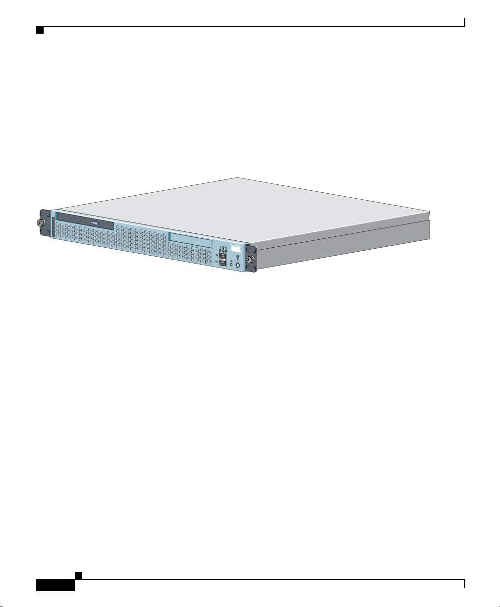
Figure 1-1.)
Figure 1-1 WAE-511 and WAE-611—Front View
The WAE-511 and WAE-611 are configured for AC-input power and have a single
AC-input power supply.
The WAE appliance has an integrated dual-port Ethernet controller. This
controller provides an interface for connecting to 10-Mbps, 100-Mbps, or
1000-Mbps networks.
Wide Area Application Engines have two
10BASE-T/100BASE-TX/1000BASE-TX Ethernet ports with RJ-45 receptacles.
Both Ethernet ports support autodetect speed mode and full-duplex operation,
which enable simultaneous transmission and reception of data on the
Ethernet LAN.
115770
1-2
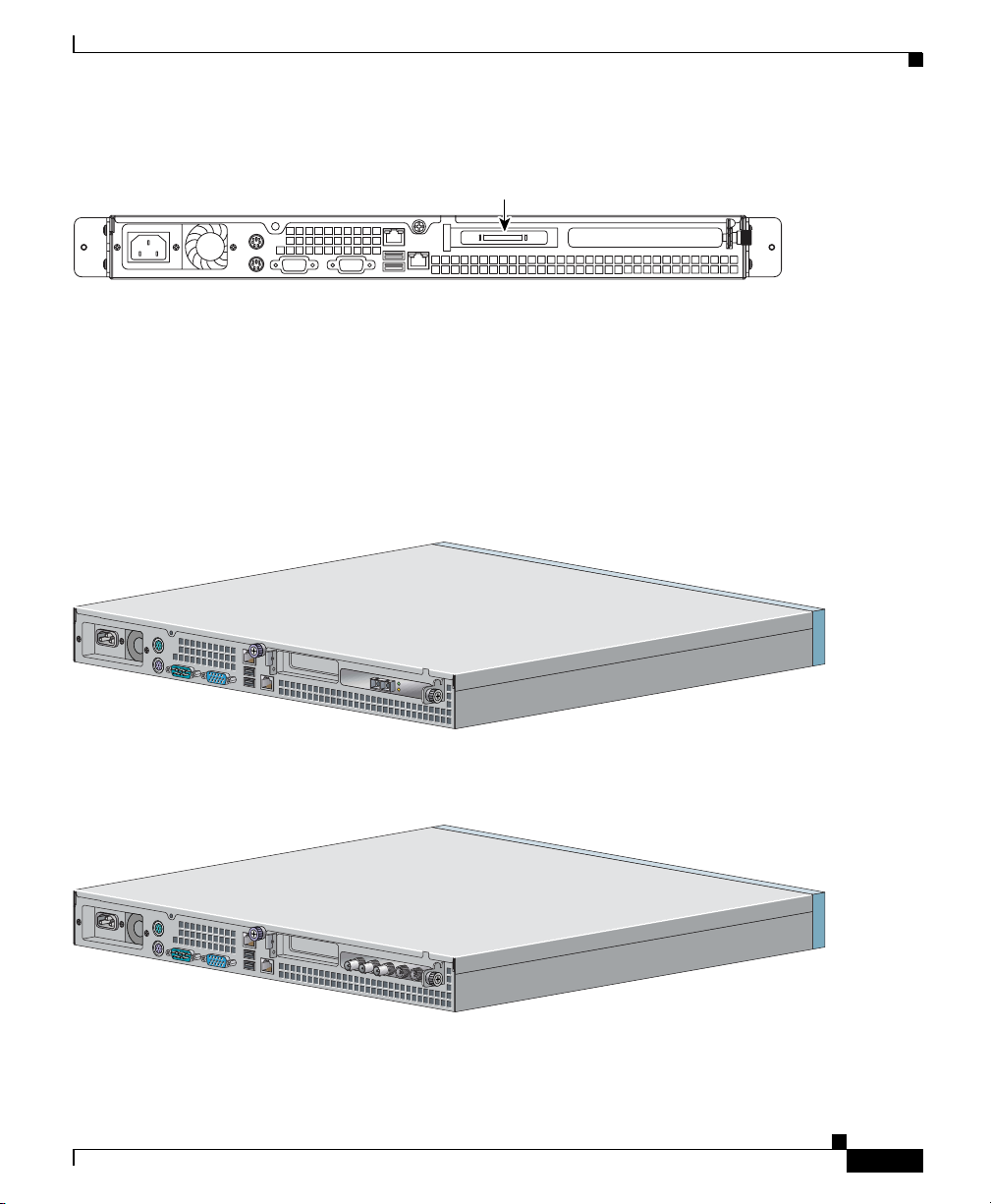
In addition, the WAE-611 is configured with one Ultra320 low-voltage
differential (LVD) small computer system interface (SCSI) port connector for
attaching the Cisco Storage Array. This connector is located in Peripheral
Component Interconnect-Extended (PCI-X) slot 2 on the back panel. (See
Figure 1-2.)
Cisco Wide Area Application Engine 511 and 611 Hardware Installation Guide
OL-7220-02
Page 25
Chapter 1 Introducing the Cisco Wide Area Application Engine
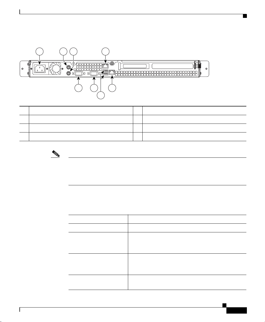
Figure 1-2 WAE-611 Back Panel with SCSI Port Connector
SCSI port connector
WAE-511 and 611 models can be configured with either a Fibre Channel adapter
or an MPEG A/V decoder adapter. These adapters are user-replaceable and are
installed in PCI-X slot 1 on the back panel.
Figure 1-3 shows the WAE-511 and WAE-611 back panel with a Fibre Channel
adapter installed in slot PCI 1, and Figure 1-4 shows the WAE back panel with an
MPEG A/V decoder adapter installed in slot PCI 1.
Figure 1-3 WAE-511 and WAE-611 Back Panel with Fibre Channel Adapter
Introduction
124684
Figure 1-4 WAE-511 and WAE-611 Back Panel with MPEG A/V Decoder Adapter
Cisco Wide Area Application Engine 511 and 611 Hardware Installation Guide
OL-7220-02
124656115771
1-3
Page 26

Chapter 1 Introducing the Cisco Wide Area Application Engine
Software Functional Description
Software Functional Description
The operation of the WAE is dependent on the software application that is
installed on it. This section describes WAAS, ACNS and WAFS software:
• WAAS Software Description, page 1-4
• ACNS Software Description, page 1-5
• WAFS Software Description, page 1-5
WAAS Software Description
With WAAS software installed, the WAE appliance functions as either a WAAS
Central Manager or a WAAS Application Acceleration Engine. The WAAS
Central Manager provides a graphical user interface to monitor and configure all
Acceleration Engines. The WAAS Acceleration Engine is deployed in remote
branch offices and in the data center to accelerate TCP applications that access
data across the network.
The Application Acceleration Engine functionality operates at different levels
based on the software licenses purchased. WAAS 4.x, software offers the WAAS
Transport License or the WAAS Enterprise License options.
Cisco WAAS software helps enterprises meet the following objectives:
1-4
• Provide branch office employees with LAN-like access to information and
applications across a geographically distributed network.
• Migrate application and file servers from branch offices into centrally
managed data centers.
• Minimize unnecessary WAN bandwidth consumption through the use of
advanced compression algorithms.
• Provide print services to branch office users. Cisco WAAS allows you to
configure a WAE as a print server so you do not need to deploy a dedicated
system to fulfill print requests.
• Improve application performance over the WAN by addressing the following
common issues:
–
Low data rates (constrained bandwidth)
–
Slow delivery of frames (high network latency)
–
Higher rates of packet loss (low reliability)
Cisco Wide Area Application Engine 511 and 611 Hardware Installation Guide
OL-7220-02
Page 27

Chapter 1 Introducing the Cisco Wide Area Application Engine
ACNS Software Description
With ACNS software installed, the WAE appliance functions as a Content
Distribution Manager, Content Engine, or Content Router. The Content
Distribution Manager provides a graphical user interface to manage registered
Content Engines and Content Routers. The ACNS solution addresses the need to
distribute and receive high-bandwidth, media-rich content across the Internet or
an intranet without performance losses or content-delivery delays.
ACNS software offers the following content-based services:
• Content caching and hosting
• Proxy services
• Content replication
• Video streaming
In Content Engine mode, the WAE operates either as a component of an ACNS
network or as a standalone content-caching device and is generally positioned on
the WAN edge between your enterprise network and the Internet.
Software Functional Description
Note The WAE-611 supports device-mode configuration and can be configured with
ACNS 5.x software to operate as a Content Engine, a Content Router, a Content
Distribution Manager, or an IP/TV Program Manager. The WAE-511 operates as
a Content Engine only.
To deploy Cisco Content Engines with Cisco ACNS software within your existing
network, your network must support Cisco IOS software and the Web Cache
Communication Protocol (WCCP). WCCP transparently redirects HTTP requests
to a Content Engine, and the Content Engine responds to those requests.
WAFS Software Description
With WAFS software installed, the WAE appliance functions as a File Engine.
The File Engine is an Internet file delivery device that provides the following
file-based services:
• Segment-level file and metadata caching
• Protocol-specific latency reduction
Cisco Wide Area Application Engine 511 and 611 Hardware Installation Guide
OL-7220-02
1-5
Page 28
Hardware Features
• WAN transport-level optimization
• Policy-based prepositioning
• Global locking and coherency
• Native end-to-end CIFS/NFS support
• Web-based centralized control and management
• Branch file server replacement
Hardware Features
This section illustrates and describes the front and back panel controls, ports, and
LED indicators on the WAE-511 and WAE-611. It contains the following topics:
• Front Panel Control Buttons, page 1-6
• LED Indicators, page 1-7
• Input/Output Ports and Connectors, page 1-10
• Inline Network Adapter Description, page 1-16
Chapter 1 Introducing the Cisco Wide Area Application Engine
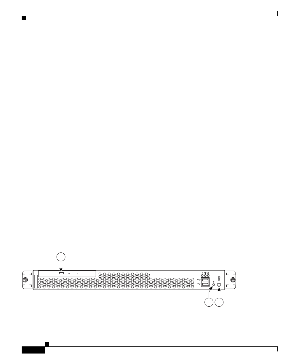
Front Panel Control Buttons
Figure 1-5 shows the WAE front panel, and Tab le 1-1 describes the front panel
control buttons.
Figure 1-5 WAE-511 and WAE-611 Front Panel
1
Cisco Wide Area Application Engine 511 and 611 Hardware Installation Guide
1-6
124658
23
OL-7220-02
Page 29
Chapter 1 Introducing the Cisco Wide Area Application Engine
Hardware Features
1 CD eject button 2 Power control button
3 Reset button
Table 1-1 Front Panel Control Buttons
Item Description
CD eject button Releases a CD from the drive.
Power control button Powers up the device.
Reset button Resets the device and runs the power-on self-test (POST). You might need
to use a pen or the end of a straightened paper clip to press the button.
Note This is a hardware reset button and does not restore the device to the
factory default software settings.
LED Indicators
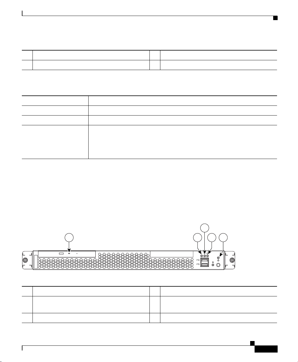
Figure 1-6 shows the location of front panel LEDs, and Table 1-2 describes
their function.
Figure 1-6 Front Panel LEDs
1 234 5
1 CD-ROM drive activity 2 System error
3 System locator (not supported on
4 Hard disk drive activity
Content Engine models)
5 Power
Cisco Wide Area Application Engine 511 and 611 Hardware Installation Guide
OL-7220-02
115772
1-7
Page 30
Chapter 1 Introducing the Cisco Wide Area Application Engine
Hardware Features
Table 1-2 Front Panel LEDs
LED Color State Description
CD-ROM drive
activity
System error Amber On A system error has occurred.
Hard disk drive
activity
Power Green On Power is flowing to the device.
Figure 1-7 Back Panel LEDs
Green On The CD-ROM drive is in use.
Green Flashing The associated hard disk drive is in use.
Flashing The device is in standby mode.
Figure 1-7 shows the location of back panel LEDs, and Table 1-3 describes
their function.
1 2
115803
4 3
1 Ethernet 1 link 2 Ethernet 1 activity
3 Ethernet 2 activity 4 Ethernet 2 link
Table 1-3 Back Panel LEDs
Indicator Color State Description
Ethernet 1 link Green On The speed of the Ethernet LAN is 1000BASE-TX.
Off The speed of the Ethernet LAN is
10BASE-T/100BASE-TX.
Cisco Wide Area Application Engine 511 and 611 Hardware Installation Guide
1-8
OL-7220-02
Page 31

Chapter 1 Introducing the Cisco Wide Area Application Engine
Hardware Features
Table 1-3 Back Panel LEDs
Indicator Color State Description
Ethernet 1 activity Green Blinking There is an active link connection on the
10/100/1000BASE-T interface for Ethernet port 1.
Ethernet 2 activity Green Blinking There is an active link connection on the
10/100/1000BASE-T interface for Ethernet port 2.
Ethernet 2 link Green On The speed of the Ethernet LAN is 1000BASE-TX.
Off The speed of the Ethernet LAN is
10BASE-T/100BASE-TX.
Figure 1-8 shows the LEDs for the Fibre Channel adapter, and Ta b le 1- 4 describes
their function.
Figure 1-8 Fibre Channel Adapter LEDs
Note In the illustration, the top LED is green, and the bottom LED is amber.
Table 1-4 Fibre Channel Adapter LEDs
LED State Meaning
Green
Amber
Green
Amber
OL-7220-02
On
Power is on.
On
On
Fibre Channel adapter is online.
Off
Cisco Wide Area Application Engine 511 and 611 Hardware Installation Guide
83287
1-9
Page 32

Chapter 1 Introducing the Cisco Wide Area Application Engine
Hardware Features
Table 1-4 Fibre Channel Adapter LEDs (continued)
LED State Meaning
Green
Amber
Green
Off
On
Off
Signal has been acquired. (The Fibre Channel
adapter firmware is performing or waiting to
perform Fibre Channel loop initialization.)
Loss of synchronization.
Amber
Green
Amber
Note The MPEG A/V decoder adapter does not have any LEDs.
Flashing
Flashing
Flashing
Firmware error.
Input/Output Ports and Connectors
Your WAE appliance supports the following I/O connectors on the back of the
device:
• Ethernet connectors
• Serial connector
• SCSI low-voltage differential (LVD) connector (WAE-611 only)
• Fibre Channel connector (on optional adapter)
• Video and audio connectors (on optional adapter)
Warning
To avoid electric shock, do not connect safety extra-low voltage (SELV) circuits
to telephone-network voltage (TNV) circuits. LAN ports contain SELV circuits,
and WAN ports contain TNV circuits. Some LAN and WAN ports both use RJ-45
connectors. Use caution when connecting cables.
Statement 1021
1-10
Figure 1-9 shows the location of the WAE back panel ports and receptacles.
Cisco Wide Area Application Engine 511 and 611 Hardware Installation Guide
OL-7220-02
Page 33
Chapter 1 Introducing the Cisco Wide Area Application Engine
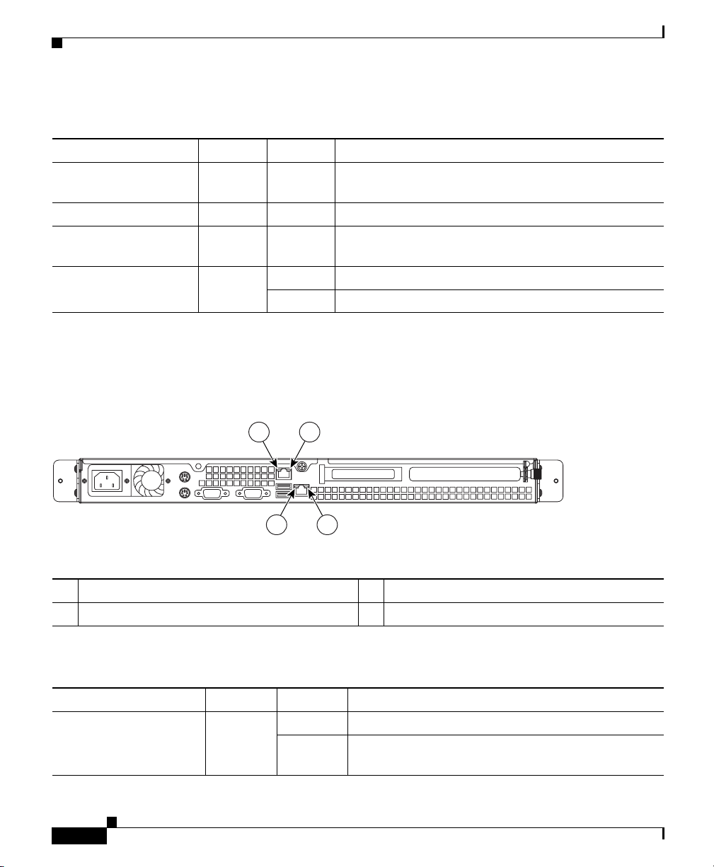
Figure 1-9 WAE-511 and WAE-611 Back Panel Ports and Receptacles
1 2 3 4
8 7 5
6
1 AC power receptacle 2 Mouse port
3 Keyboard port 4 Ethernet 1 receptacle
5 Ethernet 2 receptacle 6 USB ports (not supported)
7 Monitor port 8 Serial port
Note Cisco ACNS and WAFS software do not support the use of a keyboard or mouse
(Personal System 2 [PS/2] or Universal Serial Bus [USB]). However, keyboard
and mouse are supported by the BIOS for power-on self-test (POST), and the
configuration/setup utility.
Hardware Features
115773
OL-7220-02
Table 1-5 describes the back panel ports and receptacles.
Table 1-5 Back Panel Ports and Connectors
Item Description
AC power receptacle The AC power cord connects to this plug.
Ethernet 1 port This 10/100/1000BASE-T port is autosensing with
full-duplex capability; it connects your device to the
Ethernet LAN.
Ethernet 2 port This 10/100/1000BASE-T port is autosensing with
full-duplex capability; it connects your device to the
Ethernet LAN.
Serial port This is a standard serial port for connecting to a
console or terminal.
Cisco Wide Area Application Engine 511 and 611 Hardware Installation Guide
1-11
Page 34

Hardware Features
Chapter 1 Introducing the Cisco Wide Area Application Engine
Table 1-5 Back Panel Ports and Connectors (continued)
Item Description
SCSI LVD port
(WAE-611 only) (See
Figure 1-2)
Fibre Channel port (on
optional adapter)
Audio/video port (on
optional MPEG A/V
decoder adapter)
1. SAN = storage area network
2. BNC = Bayonet Neill-Concelman
3. RGB = red green blue
4. S/PDIF = Sony/Philips Digital Interface
5. VGA = video graphics array
Use this port to attach an external Cisco
Storage Array device.
This port provides the option to connect to an
external Fibre Array device or SAN
storage capacity.
• 3 BNC
2
connectors for YUV, RGB3, and
composite video output
• Mini-XLR 8-pin connector for S/PDIF
analog stereo audio output
• Mini-XLR 8-pin connector for VGA
1
for added data
4
and
5
output
Ethernet Port Connector
The WAE appliance comes with one integrated dual-port Ethernet controller. This
controller provides an interface for connecting to 10-Mbps, 100-Mbps, or
1000-Mbps networks and provides full-duplex (FDX) capability, which enables
simultaneous transmission and reception of data on the Ethernet LAN.
To access the Ethernet port, connect a Category 3, 4, or 5 unshielded twisted-pair
(UTP) cable to the RJ-45 connector on the back of the device.
Note The 100BASE-TX/1000BASE-TX Ethernet standard requires that the cabling in
the network be Category 5 or higher.
Figure 1-10 shows the pin number assignments for the Ethernet RJ-45 port.
Cisco Wide Area Application Engine 511 and 611 Hardware Installation Guide
1-12
OL-7220-02
Page 35
Chapter 1 Introducing the Cisco Wide Area Application Engine
Figure 1-10 Ethernet Port Connector
Hardware Features
Activity LED
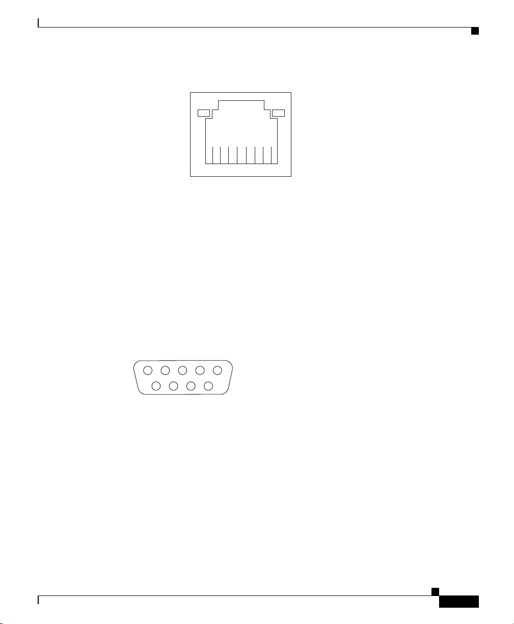
Serial Port Connector
The WAE appliance has one standard serial port connector located on the back of
the device.
Figure 1-11 shows the pin number assignments for the 9-pin, male D-shell serial
port connector on the back of the device. These pin number assignments conform
to the industry standard.
Figure 1-11 Serial Port Connector
1
(green)
8
5
83193
69
Link LED
(green)
83195
1
SCSI Port Connector
The WAE-611 has one SCSI LVD port connector located on the back of the
device. A cable for this port is provided when you purchase a Cisco
Storage Array.
When you attach an external SCSI device to the SCSI connector, you must set a
unique ID for the device. Refer to the information that comes with the device for
instructions on how to set its SCSI ID.
OL-7220-02
Cisco Wide Area Application Engine 511 and 611 Hardware Installation Guide
1-13
Page 36

Hardware Features
Chapter 1 Introducing the Cisco Wide Area Application Engine
Figure 1-12 shows a 68-pin, female D-shell SCSI connector. These connectors
conform to the SCSI standard.
Figure 1-12 SCSI Port Connector
34
68
Fibre Channel Port Connector
The WAE-511 and WAE-611 support one optional Fibre Channel adapter that has
a single Fibre Channel port.
The Fibre Channel connector (see Figure 1-13) is an LC-style connector that
supports nonoptical fibre conductive (nonOFC), multimode fiber-optic cabling
using a small form factor (SFF) fiber-optic transceiver module. The Fibre Channel
adapter uses LC-LC Fibre Channel cables. The total cable length should not
exceed 1640 feet (500 meters). Fibre Channel cables are not supplied by
Cisco Systems.
Figure 1-13 Fibre Channel Connector
1
83192
35
1-14
83287
Cisco Wide Area Application Engine 511 and 611 Hardware Installation Guide
OL-7220-02
Page 37

Chapter 1 Introducing the Cisco Wide Area Application Engine
Video Port Connectors
The WAE-511 and WAE-611 support one optional MPEG A/V decoder adapter
that has one audio and video input/output port.
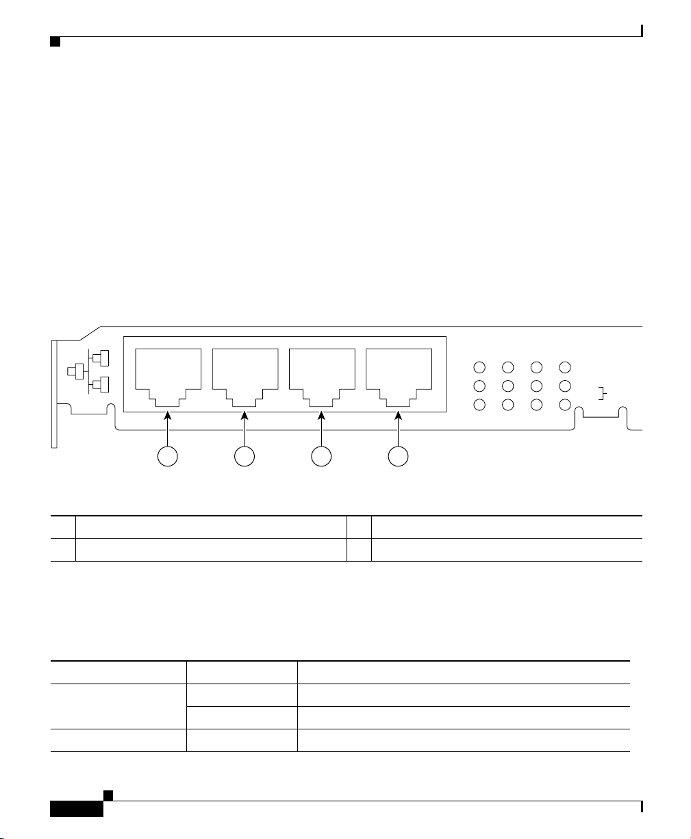
Figure 1-14 shows the following five connectors for the audio and video
input/output port:
• 3 BNC connectors for YUV, RGB, and composite video output
• Mini-XLR 8-pin connector for Sony/Philips Digital Interface (S/PDIF) and
analog stereo audio output
• Mini-XLR 8-pin connector for video graphics array (VGA) output
Figure 1-14 Video Input/Output Connectors
Hardware Features
83288
OL-7220-02
Table 1-6 provides the pinout for the audio output mini-XLR 8-pin connector, and
Table 1-7 provides the pinout for the VGA output mini-XLR 8-pin connector.
Table 1-6 Audio Output Connector Pinout
Pin Number Destination
1 Audio left (–)
2Ground
3 Audio left (+)
4 Audio right (+)
5Ground
6 Audio left (–)
7Ground
8S/PDIF
Cisco Wide Area Application Engine 511 and 611 Hardware Installation Guide
1-15
Page 38

Chapter 1 Introducing the Cisco Wide Area Application Engine
Hardware Features
Table 1-7 VGA Output Connector Pinout
Pin Number Destination
1Vsync
2Ground
3Hsync
4Blue
5Ground
6Red
7 Green
8Ground
Inline Network Adapter Description
This section describes the following features of the WAE inline network adapter:
Form and Function
Cisco Wide Area Application Engine 511 and 611 Hardware Installation Guide
1-16
• Form and Function
• Ports and LED Indicators
For adapter specifications, see Table A-4 in Appendix A.
Your appliance supports one optional 4-port Ethernet inline network adapter. The
inline network adapter is a full-height, three-quarter-length PCI-X network
interface card that contains four independent Gigabit Ethernet ports. (See
Figure 1-15.)
OL-7220-02
Page 39
Chapter 1 Introducing the Cisco Wide Area Application Engine
Figure 1-15 Inline Network Adapter
The Cisco WAE inline network adapter provides inline traffic interception
capability for your appliance. When your appliance is configured for inline
interception mode, you can set attributes to control which interfaces are to be used
over which VLANs. By default, the adapter operates on all inline-capable
interfaces and VLANs. You can configure the inline redirection feature using the
WAAS 4.0.7 CLI or the WAAS 4.0.7 Central Manager GUI.
Hardware Features
159701
OL-7220-02
The WAAS software defines two new interface types: A group interface that
represents an inline pair grouping and a port interface that represents the
individual port. These interfaces are referred to as inlineGroup and inlinePort,
respectively.
InlineGroup interfaces are numbered using the format slot/group. The slot number
is the slot in which the adapter is inserted. (In the WAE 500 series and 600 series
appliances, the adapter must be installed in slot 1 only.) The group number is
either 0 or 1 (each adapter has 2 group pairs). The group number is displayed on
the adapter label.
InlinePort interfaces are numbered slot/group/lan or slot/group/wan. The last
attribute is the LAN or WAN designator.
The inline network adapter also includes an onboard programmable Watch Dog
Timer (WDT) controller. You can set the time to wait after a failure event, such as
a power outage or a kernel crash, before the unit begins to operate in mechanical
bypass mode. In mechanical bypass mode, traffic is bridged between the LAN and
WAN ports of each group. Mechanical bypass mode prevents the WAE from
Cisco Wide Area Application Engine 511 and 611 Hardware Installation Guide
1-17
Page 40
Chapter 1 Introducing the Cisco Wide Area Application Engine
S
Hardware Features
becoming a single point of failure and allows traffic to continue to flow between
the router and the client while it passes through an unresponsive WAE without
being processed.
For more information about configuring the inline network adapter, see the Cisco
Wide Area Application Services Configuration Guide.
Ports and LED Indicators
Figure 1-16 shows the inline network adapter port numbers, interface
designations, and LEDs. Tab l e 1-8 describes the LED functions.
Figure 1-16 Inline Network Adapter Port Numbering and LEDs
0 1 2 3
LINK/ACT
100
BYPAS
1000
0 1 2 3
0 Port 0; Group 1 WAN interface 1 Port 1; Group 1 LAN interface
2 Port 2; Group 0 WAN interface 3 Port 3: Group 0 LAN interface
The inline network adapter has three LEDs that correspond to each port (the 0
LEDs correspond to Port 0, and so forth). Tab le 1- 8 describes the LEDs.
Table 1-8 Inline Network Adapter LEDs
LEDs State Description
Link / Activity On The 10/100/1000BASE-T interface is receiving power.
Blinking The Ethernet link is transmitting data.
100 On The speed of the Ethernet connection is 100BASE-TX.
Cisco Wide Area Application Engine 511 and 611 Hardware Installation Guide
1-18
OL-7220-02
Page 41

Chapter 1 Introducing the Cisco Wide Area Application Engine
Hardware Features
Table 1-8 Inline Network Adapter LEDs (continued)
LEDs State Description
1000 On The speed of the Ethernet connection is 1000BASE-TX.
Bypass Both the 100 and
The corresponding ports are in mechanical bypass mode.
1000 LEDs are
on
Inline Network Adapter Cabling Requirements
Your inline network adapter ships with two types of cables: crossover and
straight-through. When you connect the WAE inline network adapter, proper
cabling depends on the link speed (Gigabit Ethernet or Fast Ethernet) and the
types of devices (DCE or DTE) being connected.
Note You must retain the same link speed from one end of the connection to the other
end. Inline adapter interfaces are able to autonegotiate link speeds. If any of your
connecting interfaces are configured for Fast Ethernet (whether on a switch or a
router), your WAE inline adapter uses Fast Ethernet. If any of your connecting
interfaces are configured for Gigabit Ethernet, your WAE inline adapter uses
Gigabit Ethernet. Speed and duplex settings are port-specific, so two inline ports
can negotiate different speeds independently.
OL-7220-02
If you are connecting a WAE inline appliance between two devices using Gigabit
Ethernet, you can use either straight-through cables, crossover cables, or any
combination of the two cable types, regardless of the type of device. However, for
consistency, we recommend that you use straight-through cables for all Gigabit
Ethernet connections.
Table 1-9 shows the cable requirements for WAE and non-WAE connections when
you are using Gigabit Ethernet end to end.
Table 1-9 Cable Requirements for WAE Connections Using Gigabit
Ethernet
Connection Required Cable
Switch to switch (no WAE) Crossover or Straight-through
Switch to router (no WAE) Crossover or Straight-through
Cisco Wide Area Application Engine 511 and 611 Hardware Installation Guide
1-19
Page 42

Hardware Features
Chapter 1 Introducing the Cisco Wide Area Application Engine
Table 1-9 Cable Requirements for WAE Connections Using Gigabit
Ethernet (continued)
Connection Required Cable
Router to router (no WAE) Crossover or Straight-through
Switch to WAE and
WA E to R ou te r
Switch to WAE and
WAE to Switch
Router to WAE and
WA E to R ou te r
WAE to WAE Crossover or Straight-through
Some switches support automatic medium-dependent interface crossover
(MDIX). You can configure MDIX by using the mdix auto global configuration
switch command. If your switch supports MDIX, you do not need to follow these
cabling rules because MDIX automatically adjusts transmit and receive pairs
when an incorrect cable type (crossover or straight-through) is installed on a
10/100 Fast Ethernet port. However, when you configure MDIX, you must also
configure the port to use autosense (not manual selection of speed/duplex).
Crossover or Straight-through
Crossover or Straight-through
Crossover or Straight-through
Crossover or Straight-through
Crossover or Straight-through
Crossover or Straight-through
1-20
Caution If you are connecting to Fast Ethernet ports on both the LAN and the WAN sides
of the WAE inline appliance, you must consider the types of devices that are being
connected, and you must use the correct cables. You must follow these cabling
instructions for the inline network adapter to work properly. (See Ta bl e 1-10 . For
illustrations and examples, see the “Installation Scenarios and Cabling Examples
for Fast Ethernet Connections” section on page 1-22.)
Cisco Wide Area Application Engine 511 and 611 Hardware Installation Guide
OL-7220-02
Page 43

Chapter 1 Introducing the Cisco Wide Area Application Engine
To connect the inline network adapter using the correct cables for Fast Ethernet
connections, follow these steps:
Step 1 Determine which type of cable you would use for a direct connection between
your two end devices (without a WAE inline network appliance connected
between them) by using the following standard cabling rules:
• When you are directly connecting two network devices that are similar, such
as two switches, use a crossover cable.
• When you are directly connecting two network devices that are different, such
as a switch and router, use a straight-through cable.
Note Because the inline network adapter has an internal crossover connection
that becomes active when the InlineGroup interface is placed in
mechanical bypass mode, you must figure out which cable you would use
to connect the two network devices directly, and then you must install the
other cable type (on one side, usually the WAN side of the inline
appliance) instead.
Hardware Features
OL-7220-02
Table 1-10 shows the cable requirements for WAE and non-WAE connections
when you are using Fast Ethernet end to end.
Table 1-10 Cable Requirements for WAE Connections Using Fast Ethernet
Connection Required Cable
Switch to switch (no WAE) Crossover
Switch to router (no WAE) Straight-through
Router to router (no WAE) Crossover
Switch to WAE and
WA E to R ou te r
Switch to WAE and
WAE to Switch
Router to WAE and
WA E to R ou te r
Straight-through
Crossover
Straight-through
Straight-through
Straight-through
Straight-through
WAE to WAE Crossover
Cisco Wide Area Application Engine 511 and 611 Hardware Installation Guide
1-21
Page 44

Hardware Features
Step 2 Connect Fast Ethernet ports on both the LAN and the WAN sides of the WAE
Chapter 1 Introducing the Cisco Wide Area Application Engine
inline appliance by using the following cable types:
• On the LAN side of the connection, use a straight-through cable between the
WAE inline appliance and the network device.
• On the WAN side of the connection, use the cable that is different from the
cable that you would use to connect the two network devices directly (as
determined in Step 1).
For example, if you are connecting a router and a switch (two different
devices) through the WAE inline appliance, use a straight-through cable on
the LAN side of the connection and use a crossover cable on the WAN side
of the connection. (If you were connecting the two different devices directly,
you would use a straight-through cable, so use the crossover cable instead.)
If you are connecting two switches (or two similar devices), use
straight-through cables on both the LAN and the WAN sides of the WAE
inline appliance.
Figure 1-17 through Figure 1-19 show the cables to use for the WAE LAN
and WAN connections between Fast Ethernet ports.
Installation Scenarios and Cabling Examples for Fast Ethernet Connections
WAE appliances can be installed physically between two network devices (such
as the branch office router and branch office LAN switch) by connecting the WAE
inline network adapter ports to the network devices using the proper cables.
If you are connecting a WAE inline appliance between two devices using Gigabit
Ethernet, you can use either straight-through cables, crossover cables, or any
combination of the two cable types, regardless of the type of device. This section
shows cabling examples for Fast Ethernet connections only, because Fast Ethernet
has specific cabling requirements.
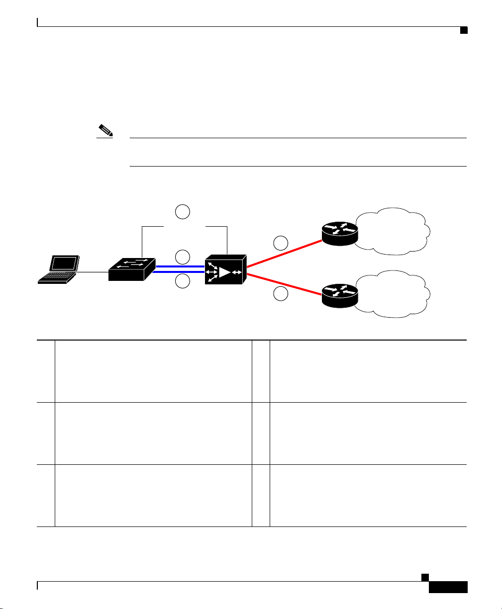
The inline network adapter has four ports that are divided into two inline groups
(see the “Ports and LED Indicators” section on page 1-18). The WAE can be
physically placed inline between two distinct network paths, creating redundant
WAN links. (See Figure 1-17.)
Cisco Wide Area Application Engine 511 and 611 Hardware Installation Guide
1-22
OL-7220-02
Page 45
Chapter 1 Introducing the Cisco Wide Area Application Engine
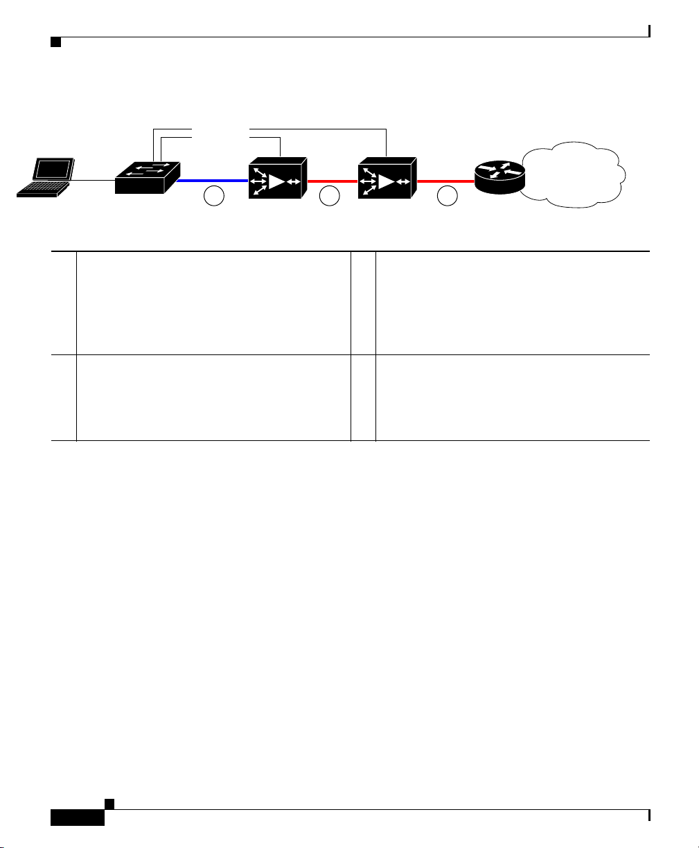
Two WAEs with inline network adapters can also be installed back-to-back in a
serial fashion between two network devices for failover purposes. In this type of
serial cluster configuration, if one WAE fails or becomes overloaded, the other
WAE can provide optimization. (See Figure 1-18.)
Note When you connect two WAE inline appliances to each other in serial fashion,
always use a crossover cable between the two WAEs. (See Figure 1-19.)
Figure 1-17 Cabling for a Single Inline WAE with Redundant WAN Connections
1
MGMT
2
4
Router A
WAN
Hardware Features
LAN switch
3
1 Connection: Management
Gigabit Ethernet: 1/0
Cable type: Straight-through (recommended)
3 Connection: WAE to LAN switch
(using InlineGroup 1/1)
Fast Ethernet: LAN1 (InlinePort 1/1/lan)
Cable type: Straight-through
5 Connection: WAE to WAN router B
(using InlineGroup 1/1)
Fast Ethernet: WAN1 (InlinePort 1/1/wan)
Cable type: Crossover
WAE
5
Router B
WAN
2 Connection: WAE to LAN switch
(using InlineGroup 1/0)
Fast Ethernet: LAN0 (InlinePort 1/0/lan)
Cable type: Straight-through
4 Connection: WAE to WAN router A
(using InlineGroup 1/0)
Fast Ethernet: WAN0 (InlinePort 1/0/wan)
Cable type: Crossover
240087
OL-7220-02
Cisco Wide Area Application Engine 511 and 611 Hardware Installation Guide
1-23
Page 46
Chapter 1 Introducing the Cisco Wide Area Application Engine
Hardware Features
Figure 1-18 Cabling for Serial Cluster Inline WAEs with a Single WAN Connection
MGMT
31 2
LAN switch
WAE1
WAE2
Router B
WAN
240088
1 Connection: WAE 1 to LAN switch
Fast Ethernet: LAN0 (InlinePort 1/0/lan)
Cable type: Straight-through
3 Connection: WAE 2 to WAN router
Fa st E th e rn et : WA E 2 WAN 0
(InlinePort 1/0/wan)
Cable type: Crossover
2 Connection: WAE 1 to WAE 2
Fast Ethernet: WAE1 WAN0
(InlinePort 1/0/wan) to WAE 2 LAN0
(InlinePort 1/0/lan)
Cable type: Crossover
1-24
Cisco Wide Area Application Engine 511 and 611 Hardware Installation Guide
OL-7220-02
Page 47
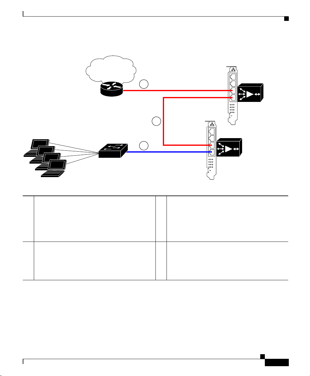
Chapter 1 Introducing the Cisco Wide Area Application Engine
a
Figure 1-19 Cabling Between Two Inline WAEs
WAN
Hardware Features
Router
LAN switch
1 Connection: WAE 1 to LAN switch
Fast Ethernet: WAE 1 LAN0
(InlinePort 1/0/lan)
Cable type: Straight-through
3 Connection: WAE 2 to WAN router
Fa st E th e rn et : WA E 2 WAN 0
(InlinePort 1/0/wan)
Cable type: Crossover
3
2
1
0 1 2 3
LINK/ACT
100
1000
BYPASS
2 Connection: WAE 1 to WAE 2
Fa st E th e rn et : WA E 1 WAN 0
(InlinePort 1/0/wan) to WAE 2 LAN0
(InlinePort 1/0/lan)
Cable type: Crossover
0 1 2 3
LINK/ACT
100
1000
BYPASS
WAE1
inline adapter
WAE2
inline ad
240089
OL-7220-02
Cisco Wide Area Application Engine 511 and 611 Hardware Installation Guide
1-25
Page 48

Hardware Features
Chapter 1 Introducing the Cisco Wide Area Application Engine
1-26
Cisco Wide Area Application Engine 511 and 611 Hardware Installation Guide
OL-7220-02
Page 49

CHAPTER
2
Preparing to Install the Cisco Wide Area Application Engine
This chapter contains important safety information you should know before
working with the Wide Area Application Engine (WAE). Use the guidelines in
this chapter to ensure your own personal safety and to help protect your device
from potential damage.
This chapter contains the following sections:
• Safety Warnings, page 2-1
• Safety Guidelines, page 2-4
Note Read the Regulatory Compliance and Safety Information for the Cisco Content
Networking Product Series document that came with your device before you
begin the installation.
Safety Warnings
Before you install the device, observe the safety warnings in this section.
Warning
OL-7220-02
Only trained and qualified personnel should be allowed to install, replace, or
service this equipment.
Cisco Wide Area Application Engine 511 and 611 Hardware Installation Guide
Statement 1030
2-1
Page 50

Safety Warnings
Chapter 2 Preparing to Install the Cisco Wide Area Application Engine
Warning
Warning
Warning
Warning
Warning
Read the installation instructions before connecting the system to the power
source.
Statement 1004
Before working on a system that has an on/off switch, turn OFF the power and
unplug the power cord.
Statement 1
This unit might have more than one power supply connection. All connections
must be removed to de-energize the unit.
Statement 1028
This unit is intended for installation in restricted access areas. A restricted
access area is where access can only be gained by service personnel through
the use of a special tool, lock and key, or other means of security, and is
controlled by the authority responsible for the location.
Statement 37
To avoid electric shock, do not connect safety extra-low voltage (SELV) circuits
to telephone-network voltage (TNV) circuits. LAN ports contain SELV circuits,
and WAN ports contain TNV circuits. Some LAN and WAN ports both use RJ-45
connectors. Use caution when connecting cables.
Statement 1021
2-2
Warning
This product relies on the building’s installation for short-circuit (overcurrent)
protection. Ensure that a fuse or circuit breaker no larger than 120 VAC, 15A U.S.
(240 VAC, 10A international) is used on the phase conductors (all
Warning
current-carrying conductors).
This equipment must be grounded. Never defeat the ground conductor or
Statement 13
operate the equipment in the absence of a suitably installed ground conductor.
Contact the appropriate electrical inspection authority or an electrician if you
are uncertain that suitable grounding is available.
Cisco Wide Area Application Engine 511 and 611 Hardware Installation Guide
Statement 1024
OL-7220-02
Page 51

Chapter 2 Preparing to Install the Cisco Wide Area Application Engine
Safety Warnings
Warning
Warning
Warning
Warning
Warning
Do not work on the system or connect or disconnect cables during periods of
lightning activity.
Statement 1001
Before working on equipment that is connected to power lines, remove jewelry
(including rings, necklaces, and watches). Metal objects will heat up when
connected to power and ground and can cause serious burns or weld the metal
object to the terminals.
Statement 43
When installing or replacing the unit, the ground connection must always be
made first and disconnected last.
Statement 1046
The safety cover is an integral part of the product. Do not operate the unit
without the safety cover installed. Operating the unit without the cover in place
will invalidate the safety approvals and pose a risk of fire and electrical
hazards.
Statement 117
Blank faceplates and cover panels serve three important functions: they
prevent exposure to hazardous voltages and currents inside the chassis; they
contain electromagnetic interference (EMI) that might disrupt other equipment;
and they direct the flow of cooling air through the chassis. Do not operate the
system unless all cards, faceplates, front covers, and rear covers are in place.
Statement 1029
OL-7220-02
Warning
Warning
There is the danger of explosion if the battery is replaced incorrectly. Replace
the battery only with the same or equivalent type recommended by the
manufacturer. Dispose of used batteries according to the manufacturer’s
instructions.
Statement 1015
Ultimate disposal of this product should be handled according to all national
laws and regulations.
Cisco Wide Area Application Engine 511 and 611 Hardware Installation Guide
Statement 1040
2-3
Page 52

Safety Guidelines
Chapter 2 Preparing to Install the Cisco Wide Area Application Engine
Warning
To prevent bodily injury when mounting or servicing this unit in a rack, you
must take special precautions to ensure that the system remains stable. The
following guidelines are provided to ensure your safety:
• This unit should be mounted at the bottom of the rack if it is the only unit in the rack.
• When mounting this unit in a partially filled rack, load the rack from the bottom to the
top with the heaviest component at the bottom of the rack.
• If the rack is provided with stabilizing devices, install the stabilizers before mounting
or servicing the unit in the rack.
Safety Guidelines
To reduce the risk of bodily injury, electrical shock, fire, and damage to the
equipment, observe the precautions in this section.
General Precautions
Observe the following general precautions for using and working with your
system:
• Observe and follow service markings. Do not service any Cisco product
except as explained in your system documentation. Opening or removing
covers that are marked with the triangular symbol with a lightning bolt may
expose you to electrical shock. Components inside these compartments
should be serviced only by an authorized service technician.
Statement 1006
2-4
• If any of the following conditions occur, unplug the product from the
electrical outlet and replace the part or contact your authorized service
provider:
–
The power cable, extension cord, or plug is damaged.
–
An object has fallen into the product.
Cisco Wide Area Application Engine 511 and 611 Hardware Installation Guide
OL-7220-02
Page 53

Chapter 2 Preparing to Install the Cisco Wide Area Application Engine
–
The product has been exposed to water.
–
The product has been dropped or damaged.
–
The product does not operate correctly when you follow the operating
instructions.
• Keep your system components away from radiators and heat sources. Also,
do not block cooling vents.
• Do not spill food or liquids on your system components, and never operate
the product in a wet environment.
• Do not push any objects into the openings of your system components. Doing
so can cause fire or electric shock by shorting out interior components.
• Use the product only with other Cisco-approved equipment.
• Allow the product to cool before removing covers or touching internal
components.
• Use the correct external power source. Operate the product only from the type
of power source indicated on the electrical ratings label. If you are not sure
of the type of power source required, consult your service representative or
local power company.
• Use only approved power cables. If you have not been provided with a power
cable for your system or for any AC-powered option intended for your
system, purchase a power cable that is approved for use in your country. The
power cable must be rated for the product and for the voltage and current
marked on the product’s electrical ratings label. The voltage and current
rating of the cable should be greater than the ratings marked on the product.
Safety Guidelines
OL-7220-02
• To help prevent electric shock, plug the system components and peripheral
power cables into properly grounded electrical outlets. These cables are
equipped with three-prong plugs to help ensure proper grounding. Do not use
adapter plugs or remove the grounding prong from a cable. If you must use
an extension cord, use a three-wire cord with properly grounded plugs.
• Observe extension cord and power strip ratings. Make sure that the total
ampere rating of all products plugged into the extension cord or power strip
does not exceed 80 percent of the extension cord or power strip ampere
ratings limit.
• Do not use appliance or voltage converters or kits sold for appliances with
your product.
Cisco Wide Area Application Engine 511 and 611 Hardware Installation Guide
2-5
Page 54

Chapter 2 Preparing to Install the Cisco Wide Area Application Engine
Safety Guidelines
• To help protect your system components from sudden, transient increases and
decreases in electrical power, use a surge suppressor, line conditioner, or
uninterruptible power supply (UPS).
• Position cables and power cords carefully; route cables and the power cord
and plug so that they cannot be stepped on or tripped over. Be sure that
nothing rests on your system components’ cables or power cord.
• Do not modify power cables or plugs. Consult a licensed electrician or your
power company for site modifications. Always follow your local or national
wiring rules.
Protecting Against Electrostatic Discharge
Static electricity can harm delicate components inside the device. To prevent
static damage, discharge static electricity from your body before you touch any of
your system’s electronic components. You can do so by touching an unpainted
metal surface on the chassis.
You can also take the following steps to prevent damage from electrostatic
discharge (ESD):
• When unpacking a static-sensitive component from its shipping carton, do not
remove the component from the antistatic packing material until you are
ready to install the component in your system. Just before unwrapping the
antistatic packaging, be sure to discharge static electricity from your body.
• When transporting a sensitive component, first place it in an antistatic
container or packaging.
• Handle all sensitive components in a static-safe area. If possible, use
antistatic floor pads and workbench pads.
Rack Installation Safety Guidelines
Before installing your device in a rack, review the following guidelines:
• Two or more people are required to install the device in a rack.
• Ensure that the room air temperature is below 95°F (35°C).
• Do not block any air vents; usually 6 inches (15 cm) of space provides
proper airflow.
Cisco Wide Area Application Engine 511 and 611 Hardware Installation Guide
2-6
OL-7220-02
Page 55

Chapter 2 Preparing to Install the Cisco Wide Area Application Engine
• Plan the device installation starting from the bottom of the rack.
• Install the heaviest device in the bottom of the rack.
• Do not extend more than one device out of the rack at the same time.
• Remove the rack doors and side panels to provide easier access during
installation.
• Connect the device to a properly grounded outlet.
• Do not overload the power outlet when installing multiple devices in the rack.
• Do not place any object weighing more than 110 lb (50 kg) on top of
rack-mounted devices.
Safety Guidelines
OL-7220-02
Cisco Wide Area Application Engine 511 and 611 Hardware Installation Guide
2-7
Page 56

Safety Guidelines
Chapter 2 Preparing to Install the Cisco Wide Area Application Engine
2-8
Cisco Wide Area Application Engine 511 and 611 Hardware Installation Guide
OL-7220-02
Page 57

CHAPTER
3
Installing the Cisco Wide Area Application Engine
This chapter explains how to install the Cisco Wide Area Application Engine
(WAE) 511 and WAE 611 in an equipment rack. It also provides general
instructions for installing the device on a table or workbench. This chapter
contains the following sections:
• Tools and Parts Required, page 3-2
• Installing the Cisco Wide Area Application Engine, page 3-2
• Connecting Cables, page 3-13
• Connecting Power and Booting the System, page 3-14
• Checking the LEDs, page 3-15
• Removing or Replacing a Cisco Wide Area Application Engine, page 3-15
Before you begin the installation, read the Regulatory Compliance and Safety
Information for the Cisco Content Networking Product Series document that
shipped with your device.
OL-7220-02
Warning
Read the installation instructions before connecting the system to the power
source.
Statement 1004
Cisco Wide Area Application Engine 511 and 611 Hardware Installation Guide
3-1
Page 58

Chapter 3 Installing the Cisco Wide Area Application Engine
Tools and Parts Required
Tools and Parts Required
A sliding rail rack-mount kit and cable management assembly is included in your
shipping container accessory box. The rack-mount kit is suitable for mounting the
device in a 19-inch (48.26-cm) four-post equipment rack.
Angle brackets for mounting the device in a two-post rack are also included in
your shipping container.
You need the following parts and tools to install the device in a rack:
• Flat-blade screwdriver
• Phillips screwdriver
• One rack-mount kit
• Documentation
Installing the Cisco Wide Area Application Engine
3-2
Place the device in the desired location. You can mount it in a rack for your
convenience, or place it on a solid, stable surface. If you do not plan to install the
unit in an equipment rack, proceed to the “Installing the Chassis on a Tabletop”
section on page 3-12.
Racks are marked in vertical increments of 1.75 inches (4.44 cm). Each increment
is referred to as a rack unit (RU). A 1-RU device is 1.75 inches (4.44 cm) tall.
Cisco Wide Area Application Engine 511 and 611 Hardware Installation Guide
OL-7220-02
Page 59

Chapter 3 Installing the Cisco Wide Area Application Engine
Installing the Cisco Wide Area Application Engine
Warning
To prevent bodily injury when mounting or servicing this unit in a rack, you
must take special precautions to ensure that the system remains stable. The
following guidelines are provided to ensure your safety:
• This unit should be mounted at the bottom of the rack if it is the only unit in the rack.
• When mounting this unit in a partially filled rack, load the rack from the bottom to the
top with the heaviest component at the bottom of the rack.
• If the rack is provided with stabilizing devices, install the stabilizers before mounting
or servicing the unit in the rack.
Statement 1006
Installing the Chassis in a Two-Post Rack
The chassis mounts to two rack posts with brackets that attach to the sides of the
chassis. These brackets are for a 19-inch (48.26-cm) equipment rack and require
four screws in each bracket. (See Figure 3-1.)
Figure 3-1 Rack-Mount Brackets
OL-7220-02
Orientation for 19-inch rack
Cisco Wide Area Application Engine 511 and 611 Hardware Installation Guide
124554
3-3
Page 60
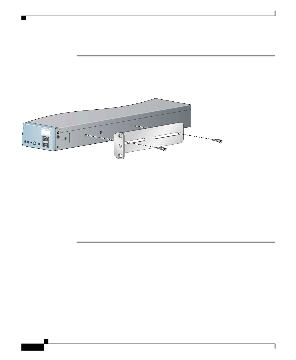
Installing the Cisco Wide Area Application Engine
To install the chassis in a two-post rack, follow these steps:
Step 1 Attach a bracket to one side of the chassis, aligning the front flange of the bracket
with the hash mark on the side of the chassis. (See Figure 3-2.)
Figure 3-2 Installing the Chassis in the Rack
Front
Chapter 3 Installing the Cisco Wide Area Application Engine
Rear
124555
Step 2
Step 3 After you secure the brackets to the chassis, rack-mount the chassis by threading
Attach a second bracket to the opposite side of the chassis in the same manner.
at least two screws through the bracket flanges on each side of the chassis into the
corresponding holes in each side of the rack. You need two people to install the
chassis in the rack—one person to hold the chassis and one person to secure it to
the rack.
The inlet and exhaust ports for cooling air are located in the front and rear of the
chassis, respectively; therefore, multiple chassis can be stacked with little or no
vertical clearance.
Installing the Chassis in a Four-Post Rack
The four-post rack-mounting system does not require any tools for installation, unless
you are shipping a device mounted in a rack. When you are shipping a device in a rack,
you need a Phillips screwdriver. Figure 3-3 shows the items that you need to install
the chassis in a four-post rack. If any items are missing or damaged, contact your
place of purchase.
Cisco Wide Area Application Engine 511 and 611 Hardware Installation Guide
3-4
OL-7220-02
Page 61
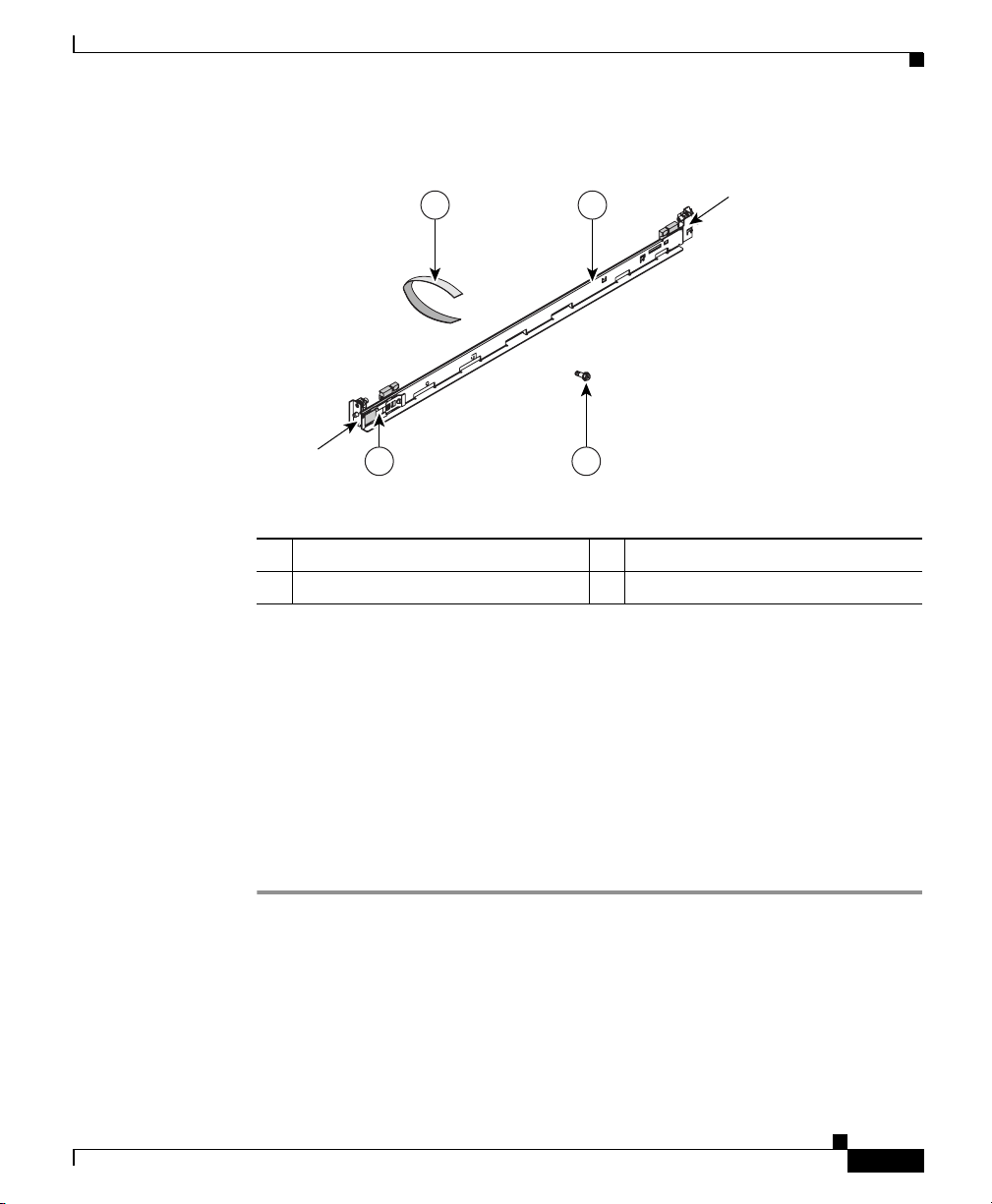
Chapter 3 Installing the Cisco Wide Area Application Engine
Figure 3-3 Rack-Mount Installation Kit
Installing the Cisco Wide Area Application Engine
4 1
Front of rail
Rear of rail
2 3
134402
1 Slide rails (2) 2 Shipping bracket
3 M6 screws (6) 4 Cable straps (6)
These slide rails come with spring-loaded locking pins at both ends of each rail.
To attach the slide rails to an equipment rack, you need to pull back the pin
carriage, align the pins with holes in the equipment rack-mounting flange, and
release the pin carriage to lock the pins into the rack posts. A rail-adjustment
bracket allows you to adjust the length of the slide rails to fit the rack. (See
Figure 3-4.)
The chassis rests on the lower ledges provided by the two rails and slides in and
out of the rack along the rail ledges.
OL-7220-02
To install the chassis in a four-post rack, follow these steps:
Step 1 To begin, open the pin carriages at the front and rear of the left slide rail:
• On the front of the rail, press on tabs labeled (2) and (3) in Figure 3-4, and slide
the pin carriage toward the rear of the rail, releasing the latch tab (2) as it catches
in place.
Cisco Wide Area Application Engine 511 and 611 Hardware Installation Guide
3-5
Page 62

Installing the Cisco Wide Area Application Engine
• On the rear of the rail, press on the two rear tabs, and slide the pin carriage toward
the front of the rail, releasing the latch tab as it catches in place. To prevent the
rail-adjustment bracket (labeled 1 in Figure 3-4) from moving during this step,
hold it in place with your thumb.
Note Slide rails are marked (RIGHT/FRONT and LEFT/FRONT) for proper
placement.
Figure 3-4 Opening the Spring-Loaded Pin Carriages—Left Slide Rail
Shown
Chapter 3 Installing the Cisco Wide Area Application Engine
4
3
2
1
1 Rail-adjustment bracket 2 Latch tab
3 Slider tab 4 Pin carriage
Step 2
To adjust the length of the slide rail, lift the release tab (labeled 1 in Figure 3-5)
and fully extend the rail-adjustment bracket from the rear of the slide rail until it
snaps into place.
Step 3 To secure the slide rail to the equipment rack, align the pins on the rear of the slide
rail with the holes on the rear mounting flange. Press the latch tab (labeled 2 in
Figure 3-5) to release the pin carriage.
3-6
Cisco Wide Area Application Engine 511 and 611 Hardware Installation Guide
OL-7220-02
Page 63

Chapter 3 Installing the Cisco Wide Area Application Engine
Note Ensure that the pins are fully extended through the mounting flange and slide
rail pin bracket. (See Figure 3-5.)
Figure 3-5 Attaching the Slide Rail to the Rear Mounting Flange—Left
Front Rail Shown
Pins extended through
the mounting flange and
slide rail pin bracket
Installing the Cisco Wide Area Application Engine
2
1
Pins not extended
through the mounting
flange and slide rail
pin bracket
134404
OL-7220-02
Step 4
1 Release tab for the rail-adjustment
2 Latch tab
bracket
To secure the front of the slide rail to the equipment rack, align the pins (labeled 1 in
Figure 3-6) on the front pin carriage to the front mounting flange. If you adjusted the
rail length, push the pin carriage back toward the rear of the slide rail. Press the latch
tab (labeled 2 in Figure 3-6) to release the front pin carriage.
Note Ensure that the pins are fully extended through the mounting flange and
the slide rail pin bracket (labeled 3 in Figure 3-6).
Cisco Wide Area Application Engine 511 and 611 Hardware Installation Guide
3-7
Page 64

Installing the Cisco Wide Area Application Engine
Figure 3-6 Attaching the Slide Rail to the Front Mounting Flange—Left
Front Rail Shown
2
Chapter 3 Installing the Cisco Wide Area Application Engine
Pins extended through
3
the mounting flange and
slide rail pin bracket
1
Pins not extended
through the mounting
flange and slide rail
pin bracket
134405
3-8
1 Pins 2 Latch tab
3 Slide rail pin bracket
Step 5
Repeat these steps for the right slide rail. Make sure that you attach the second
slide rail at the same rack height as the first one so that the chassis will be level
in the rack.
Step 6 To install the chassis in the rack, align the chassis on the slide rails and push the
chassis fully into the rack. Secure the chassis to the front mounting flanges with the
captive thumbscrews (labeled 1 in Figure 3-7).
Note You must leave the shipping brackets (labeled 2 in Figure 3-7) attached to
the slide rails unless the shipping brackets impede the chassis from
sliding fully into the rack. If you need to remove the shipping brackets,
continue with Step 7.
Cisco Wide Area Application Engine 511 and 611 Hardware Installation Guide
OL-7220-02
Page 65
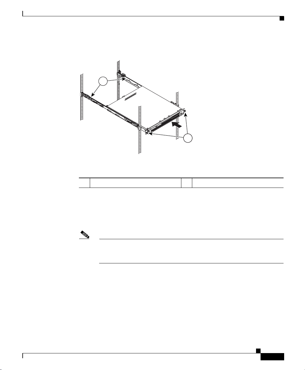
Chapter 3 Installing the Cisco Wide Area Application Engine
Figure 3-7 Inserting the Chassis onto the Slide Rails
2
1 Captive thumbscrews 2 Shipping brackets
Installing the Cisco Wide Area Application Engine
1
134406
OL-7220-02
Step 7
To remove the shipping bracket, press on the release tab (labeled 1 in Figure 3-8) as
indicated on the shipping bracket, and remove the shipping bracket from the slide rail.
Repeat this step for the other shipping bracket. Store the shipping brackets for future
use.
Note You must reinstall the shipping brackets on the slide rails before you transport
the rack with the chassis installed. To reinstall the shipping brackets, reverse
this step.
Cisco Wide Area Application Engine 511 and 611 Hardware Installation Guide
3-9
Page 66

Installing the Cisco Wide Area Application Engine
Figure 3-8 Removing the Shipping Bracket
1 Release tab
Chapter 3 Installing the Cisco Wide Area Application Engine
1
Y
,
VE
BRACKET
AND SLIDE
PUSH HERE
TO REMO
FOR SHIPPING
PURPOSES ONL
134407
3-10
Step 8
Attach the power cords and the Ethernet cables to the rear of the device. Route the
cables to the left corner of the chassis (as viewed from the rear) and use the cable
straps to secure the cables to the slide rails. (See Figure 3-9.)
Figure 3-9 Securing the Cables
Cisco Wide Area Application Engine 511 and 611 Hardware Installation Guide
134408
OL-7220-02
Page 67

Chapter 3 Installing the Cisco Wide Area Application Engine
Note Leave enough slack in the cables to allow for sliding the device in or out
of the rack.
Step 9 To transport the rack to another location with the chassis installed, you must
secure the chassis to the rack.
a. Remove one mounting screw and loosen the other mounting screws as
indicated in Figure 3-10.
Figure 3-10 Securing the Chassis for Transporting in the Rack
Installing the Cisco Wide Area Application Engine
Loosen
mounting
screws
OL-7220-02
Move mounting
screw
134410
b. If necessary, disconnect the cables from the rear of the chassis, then slide the
chassis out of the rack six inches (150 mm).
c. Fully extend the rail, and reinsert the M6 screws in each slide rail. To secure
the rail, tighten all screws. The rails should be fully extended to the rear of
the rack, and the shipping brackets should be installed.
d. Secure the chassis to the rack with the M6 screws.
To remove the chassis from the rack, reverse these instructions. Store these
installation instructions with your product documentation for future use.
Cisco Wide Area Application Engine 511 and 611 Hardware Installation Guide
3-11
Page 68

Installing the Cisco Wide Area Application Engine
Note The four-post rack-mounting system is designed for racks that do not have
pre-threaded holes. If you are using an equipment rack with pre-threaded holes,
the pins will not protrude through the rack. Instead, secure the slide rails to the
rack by attaching screws through the slide rail pin brackets at both ends of each
rail. (See Figure 3-11.)
Figure 3-11 Attaching the Slide Rails and Chassis Using M6 Screws
Chapter 3 Installing the Cisco Wide Area Application Engine
Installing the Chassis on a Tabletop
When you install a chassis on a workbench or tabletop, ensure that the surface is
clean and in a safe location and that you have considered the following:
• The chassis should be installed off the floor. (Dust that accumulates on the
floor is drawn into the interior of the chassis by the cooling fans. Excessive
dust inside the device can cause overtemperature conditions and component
failures.)
• There must be approximately 19 inches (48.26 cm) of clearance at the front
and rear of the chassis for accessing network cables or equipment.
• The device must receive adequate ventilation (it cannot be installed in an
enclosed cabinet where ventilation is inadequate).
Cisco Wide Area Application Engine 511 and 611 Hardware Installation Guide
3-12
134409
OL-7220-02
Page 69

Chapter 3 Installing the Cisco Wide Area Application Engine
To install the chassis on a workbench or tabletop, follow these steps:
Step 1 Remove any debris and dust from the tabletop or workbench, as well as from the
surrounding area. Also make sure that your path between the device and its new
location is unobstructed.
Step 2 Attach the rubber feet to the bottom of the chassis. The rubber feet have an
adhesive backing. Peel the protective tape off the adhesive and stick the feet to the
bottom of a clean chassis surface. Place one foot in each corner.
Step 3 Place the chassis on the tabletop or workbench.
Step 4 Ensure that no exhaust air from other equipment will be drawn into the chassis.
Also, make sure that there is adequate clearance at the front and rear of the
chassis.
Connecting Cables
Connecting Cables
OL-7220-02
Note The SCSI cable is part of the Cisco Storage Array accessory kit. If you did not
order the Cisco Storage Array, you did not receive a SCSI cable.
To connect network, console, and SCSI cables to the device, follow these steps:
Step 1 For network connections, insert a Category 5 UTP cable into the Ethernet 1 or
Ethernet 2 receptacle on the device back panel. (See Figure 3-12.)
Step 2 Connect the other end of the network cable to a hub or switch in your network.
Step 3 For console connections, plug the serial cable into the serial port on the device
back panel.
Step 4 Connect the other end of the console cable to a console or a communications
server.
Cisco Wide Area Application Engine 511 and 611 Hardware Installation Guide
3-13
Page 70
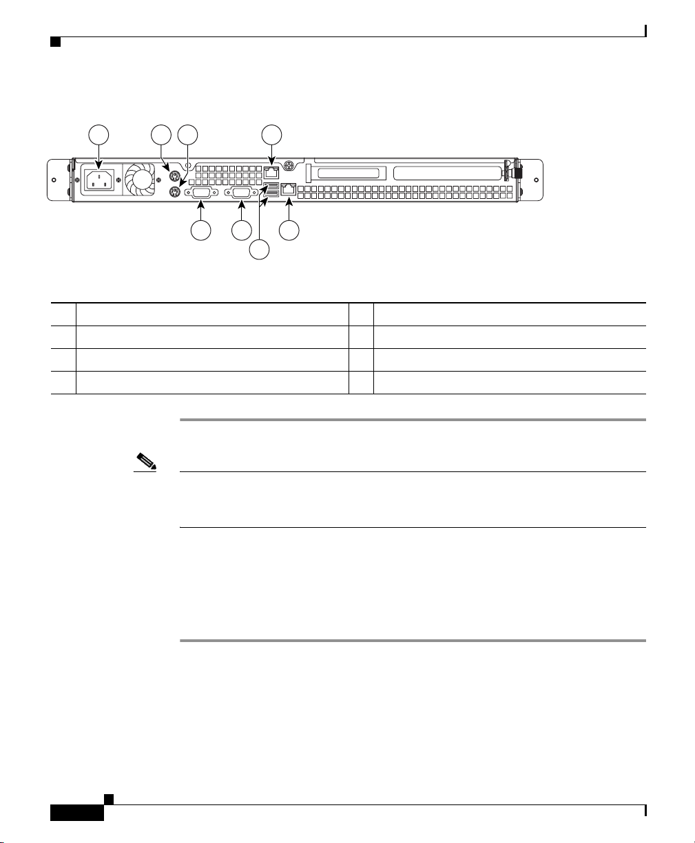
Chapter 3 Installing the Cisco Wide Area Application Engine
Connecting Power and Booting the System
Figure 3-12 WAE-511 and WAE-611 Back Panel Ports and Receptacles
1 2 3 4
8 7 5
6
1 AC power receptacle 5 Ethernet 2 receptacle
2 Mouse connector 6 USB ports (not supported)
3 Keyboard connector 7 Video connector
4 Ethernet 1 receptacle 8 Serial connector
115773
Note Cisco WAFS and ACNS software do not support the use of a keyboard or mouse
(PS/2 or USB). However, a keyboard and mouse are supported by the BIOS for
power-on self-test (POST), and the configuration or setup utility.
Connecting Power and Booting the System
To connect power to the device, follow these steps:
Step 1 Review the information in the “Safety Warnings” section on page 2-1.
Step 2 Plug the AC power cord into the power cord receptacle at the rear of the device.
(See Figure 3-12.)
Step 3 Connect the other end of the power cord to a power source at your installation site.
Step 4 Power up all externally connected devices.
Cisco Wide Area Application Engine 511 and 611 Hardware Installation Guide
3-14
OL-7220-02
Page 71

Chapter 3 Installing the Cisco Wide Area Application Engine
Step 5 Press the power control button on the front of the device.
The system should begin booting. Once the operating system boots, you are ready
to initialize the basic software configuration. (See the “Related Documentation”
section on page xiii for a list of software configuration documents.)
Note While the device is powering up, the power LED on the front of the
chassis is green.
Note You can install a circular disk over the power control button to prevent accidental
manual power down. This disk, known as the power control button shield, comes
with the device.
Checking the LEDs
Checking the LEDs
When the device is up and running, observe the front panel LEDs. To verify that
your system is operating properly, see the “LED Indicators” section on page 1-7.
Removing or Replacing a Cisco Wide Area Application Engine
Warning
Warning
OL-7220-02
Before working on a system that has an on/off switch, turn OFF the power and
unplug the power cord.
Ultimate disposal of this product should be handled according to all national
laws and regulations.
To remove a device from your network, power it down, disconnect the power
cords and network cables, and physically remove the chassis from the rack.
Cisco Wide Area Application Engine 511 and 611 Hardware Installation Guide
Statement 1
Statement 1040
3-15
Page 72

Removing or Replacing a Cisco Wide Area Application Engine
The device is in constant communication with the router on your network. When
the router notices that the device is no longer responding to it, the router stops
sending requests to the device. This is transparent to users. If other devices are
attached to the router, the router continues sending requests to the other devices.
When you remove a device, the pages that were cached on that device are no
longer available to the router or other devices, and you might see an increase in
outgoing web traffic that might have otherwise been fulfilled by the device that
you are removing. However, after a time, the router and other devices redistribute
the load of web traffic.
If you remove the last device from your network, you can also disable device
support on the router. However, this is not necessary; having device support
enabled when there are no devices attached has no effect on the router’s
performance.
To replace a device, remove it from the network, and then install a new device.
Configure it using the same configuration parameters (IP address, and so forth)
that you used for the removed device.
Chapter 3 Installing the Cisco Wide Area Application Engine
3-16
Cisco Wide Area Application Engine 511 and 611 Hardware Installation Guide
OL-7220-02
Page 73

Installing Hardware Options
This chapter provides basic instructions for installing hardware options in the
Wide Area Application Engine (WAE). These instructions are intended for
experienced technicians.
This chapter contains the following topics:
• Removing the Cover and Bezel, page 4-1
• Installing Adapters, page 4-3
• Installing DIMMs, page 4-12
• Working with Hard Disk Drives, page 4-15
• Completing the Installation, page 4-17
Removing the Cover and Bezel
CHAPTER
4
OL-7220-02
Warning
Step 1 Review the information in the “Safety Warnings” section on page 2-1, and the
Step 2 Power down the device and all attached devices. Disconnect the power cord and
Before working on a system that has an on/off switch, turn OFF the power and
unplug the power cord.
To remove the cover, follow these steps:
“Safety Guidelines” section on page 2-4.
all external cables.
Cisco Wide Area Application Engine 511 and 611 Hardware Installation Guide
Statement 1
4-1
Page 74

Removing the Cover and Bezel
Step 3 Loosen the two captive screws (1) on the rear of the cover. (See Figure 4-1.)
Figure 4-1 Removing the Cover
Chapter 4 Installing Hardware Options
1
115802
4-2
Step 4 Slide the cover back; then lift it up and off the device.
Caution For proper cooling and airflow, replace the cover before turning on the device.
Operating the device for extended periods (over 30 minutes) with the cover
removed might damage device components.
Step 5 Remove the bezel as shown in Figure 4-2.
a. Press the release tabs on the bezel and pull the bezel away from the chassis.
b. Store the bezel in a safe place.
Cisco Wide Area Application Engine 511 and 611 Hardware Installation Guide
OL-7220-02
Page 75

Chapter 4 Installing Hardware Options
Figure 4-2 Removing the Bezel
Installing Adapters
124004
Installing Adapters
This section provides general information about the system board, riser card,
adapters, and PCI-X slot configuration specifications, and contains the following
adapter installation procedures:
• Installing an MPEG Decoder Adapter, page 4-5
• Installing a Fibre Channel Adapter, page 4-8
Note These adapters are supported in ACNS software only.
Cisco Wide Area Application Engine 511 and 611 Hardware Installation Guide
OL-7220-02
4-3
Page 76

Installing Adapters
Note To install the inline network adapter, see the Installing the Cisco WAE Inline
Chapter 4 Installing Hardware Options
Network Adapter publication. The inline network adapter is supported in WAAS
4.0.7 and later software only.
Before you install adapters, review the following information:
• The device has two Peripheral Component Interconnect-Extended (PCI-X)
adapter slots:
–
PCI-X slot 1 is located on the adapter support bracket with the riser card.
To access the PCI-X slot 1 connector, you must first remove the adapter
support bracket. (See Figure 4-4.)
You can install either a Fibre Channel adapter or an MPEG A/V decoder
adapter in PCI-X slot 1. (This slot is labeled “PCI 1” on the back of the
device.)
–
PCI-X slot 2 is located on the system board and is not used in the device.
• Documentation is included with the adapter. Follow the instructions in the
adapter documentation in addition to the instructions in this chapter.
• The system scans PCI-X slots to assign system resources. By default the
system tries to boot from the CD-ROM. If the CD-ROM is not present, the
system boots from the integrated flash device.
4-4
Caution When you handle static-sensitive devices, take precautions to avoid damage from
static electricity. For details on handling these devices, see the “Protecting
Against Electrostatic Discharge” section on page 2-6.
Cisco Wide Area Application Engine 511 and 611 Hardware Installation Guide
OL-7220-02
Page 77

Chapter 4 Installing Hardware Options
Installing an MPEG Decoder Adapter
Note The illustrations in this document might differ slightly from your hardware.
To install an MPEG decoder adapter, follow these steps.
Step 1 Review the safety information in the “Safety Guidelines” section on page 2-4.
Step 2 Power down the device and peripheral devices.
Step 3 Disconnect the power cord and then all external cables from the device.
Step 4 Remove the device cover.
Note You may find it easier to route the cables before you install the adapter.
Step 5 Loosen the captive screw (labeled 4 in Figure 4-3) located on the rear of the
device adjacent to PCI-X slot 1 and remove the expansion slot cover.
Installing Adapters
OL-7220-02
Note PCI expansion slot covers must be installed on all vacant slots. This
maintains the electronic emissions characteristics of the device and
ensures proper cooling of device components.
Cisco Wide Area Application Engine 511 and 611 Hardware Installation Guide
4-5
Page 78

Installing Adapters
Figure 4-3 Removing the Expansion Slot Cover
1
Chapter 4 Installing Hardware Options
124478
2 4
3
1 Expansion slot cover (slot 2) 2 Expansion slot cover (slot 1)
3 Captive screw 4 Riser card assembly
Step 6
Remove the riser card (labeled 1 in Figure 4-4) from the system board to access
the expansion slot.
Cisco Wide Area Application Engine 511 and 611 Hardware Installation Guide
4-6
OL-7220-02
Page 79

Chapter 4 Installing Hardware Options
Figure 4-4 Installing an Adapter in PCI-X Slot 1
321
Installing Adapters
4
5
124479
6
1 Riser card 2 PCI-X slot 2 connector
3 PCI-X slot 1 connector 4 Adapter support bracket
5 Adapter 6 PCI-X riser card connector
Cisco Wide Area Application Engine 511 and 611 Hardware Installation Guide
OL-7220-02
4-7
Page 80

Installing Adapters
Step 7 Touch the static-protective package that contains the adapter to any unpainted
Step 8 Place the adapter, component-side up, on a flat, static-protective surface and set
Caution When you install an adapter in the device, be sure that it is completely and
Step 9 To install the adapter, carefully grasp the adapter by its top edge or upper corners,
Step 10 Reinstall the riser card. Make sure that the riser card is fully seated in the riser
Step 11 Tighten the captive screw for expansion slot 1.
Step 12 Connect the required cables to the adapter.
Step 13 If you have other hardware options to install, do so now; otherwise, go to the
Chapter 4 Installing Hardware Options
metal surface on the device, and then remove the adapter from the
static-protective package. Avoid touching the components and gold-plated edge
connectors on the adapter.
any jumpers or switches as described by the adapter manufacturer, if necessary.
correctly seated in the PCI expansion slot before you power up the device.
Incomplete insertion might cause damage to the system board or the adapter.
align it with the PCI-X slot 1 connector (labeled 2 in Figure 4-4), and then press
the adapter firmly into the expansion slot.
card connector (labeled 5 in Figure 4-4) on the system board.
“Completing the Installation” section on page 4-17.
Installing a Fibre Channel Adapter
Fibre Channel is a high-speed data transport technology used for mass storage and
networking. Fibre Channel technology is outlined in the SCSI-3 Fibre Channel
Protocol (SCSI-FCP).
The Fibre Channel adapter uses a multimode shortwave optical interface for
distances up to 1640 feet (500 meters). It is a 2-gigabit (Gb) Fibre Channel device
that supports data transfer rates up to 200 megabytes per second (MBps) half
duplex and 400 MBps full duplex on optical interfaces.
Cisco Wide Area Application Engine 511 and 611 Hardware Installation Guide
4-8
OL-7220-02
Page 81

Chapter 4 Installing Hardware Options
Preparing to Install the Adapter
Before you begin the installation, do these tasks:
• Read the “Fiber-Optic Cabling Guidelines for the Fibre Channel Adapter”
section.
• Read the “Tools and Parts Required” section.
• Write down the serial number for future reference.
Fiber-Optic Cabling Guidelines for the Fibre Channel Adapter
To avoid damage to your fiber-optic cables, follow these guidelines:
• Do not route the cable along a folding cable management arm.
• When attaching fiber-optic cables to a Fibre Channel device on slide rails,
leave enough slack in the cables so that they do not bend to a radius smaller
than 1.5 in. (38 mm) when extended or become pinched when retracted.
• Route the cable away from places where it can catch on other Fibre Channel
devices in the rack.
• Do not overtighten the cable straps or bend the cables to a radius smaller than
1.5 in. (38 mm).
Installing Adapters
Tools and Parts Required
To install the Fibre Channel adapter in your system, you need the following items:
OL-7220-02
• Do not put excess weight on the cable at the connection point and be sure that
the cable is well supported.
• Small Phillips screwdriver
• Logical Cable (LC)-LC Fibre Channel cable (this cable is not provided by
Cisco Systems; you must order it separately)
Cisco Wide Area Application Engine 511 and 611 Hardware Installation Guide
4-9
Page 82

Installing Adapters
Installing the Fibre Channel Adapter
To install the Fibre Channel adapter, follow these steps:
Step 1 Check the system board and locate the correct PCI-X slot for the Fibre Channel
card.
Step 2 Power down any connected peripheral devices, and then power down the device.
Step 3 Disconnect the power cords.
Step 4 Remove the cover. (See the “Removing the Cover and Bezel” section on
page 4-1.)
Step 5 Remove the expansion slot cover. (See Figure 4-3.)
Step 6 Align the adapter with the slot 2 connector on the riser card. Carefully press the
adapter into the expansion slot until it is fully seated and secure. (See Figure 4-4.)
Step 7 Reinstall the riser card. Make sure that the riser card is fully seated in the riser
card connector on the system board.
Step 8 Connect one end of an LC-LC Fibre Channel cable to the optical interface
connector on the Fibre Channel adapter card. Connect the other end to a Fibre
Channel device.
Step 9 Carefully install and secure the cover. (See the “Completing the Installation”
section on page 4-17.)
Step 10 Connect the power cables.
Chapter 4 Installing Hardware Options
Step 11 Power on all external Fibre Channel devices; then power on the device.
Step 12 Verify the installation by checking the LEDs. (See Table 1-4 on page 1-9.)
Troubleshooting the Fibre Channel Adapter Installation
Three types of adapter installation problems might cause your Fibre Channel
adapter to function incorrectly:
• Hardware problems
• System configuration problems
• Fibre Channel problems
Cisco Wide Area Application Engine 511 and 611 Hardware Installation Guide
4-10
OL-7220-02
Page 83

Chapter 4 Installing Hardware Options
Hardware Problems
To determine if your installation problem is caused by the hardware, take the
following actions:
• Verify that all adapters are installed securely.
• Verify that all cables are attached securely to the correct connectors. Be sure
that one end of the LC-LC Fibre Channel cable is attached to the optical
interface connector and that the other end is connected to the Fibre Channel
device.
• Verify that the Fibre Channel adapter is installed correctly and is fully seated
in the correct expansion slot.
• Verify that all peripheral devices are turned on.
System Configuration Problems
Verify that the Fibre Channel adapter card is installed in the correct PCI-X slot. If
you still have a system configuration problem, contact Cisco technical support for
assistance. (See the “Obtaining Technical Assistance” section on page xviii.)
Installing Adapters
Fibre Channel Problems
OL-7220-02
To determine if your installation problem is caused by an attached Fibre Channel
device, perform the following tasks:
• Verify that all of the Fibre Channel devices were turned on before you turned
on the device.
• Ensure that all cables are connected properly.
• Verify that you configured your RAID storage subsystems using the utilities
provided by the manufacturer.
• If your Fibre Channel switch supports zoning, make sure that your peripheral
device is configured to the same switch zone as the Fibre Channel adapter.
Cisco Wide Area Application Engine 511 and 611 Hardware Installation Guide
4-11
Page 84

Installing DIMMs
Installing DIMMs
Adding memory to your device is an easy way to make programs run faster. You
can increase the amount of memory in your device by installing additional
dual-inline memory modules (DIMMs). Your device uses a noninterleaved
memory configuration.
When you install additional memory, note the following information:
• Memory modules are installed on the system board in the DIMM slots shown
in Figure 4-5. Devices with a single DIMM should have the module installed
in DIMM slot 1. For devices with two DIMMs, use slots 1 and 3. For devices
with four DIMMs use slots 1, 2, 3 and 4.
• Review the memory specifications for your WAE model in the “Appliance
Specifications” section on page A-1. Note the following information
regarding software support:
–
WAFS software supports up to 1 GB of memory.
–
ACNS software supports up to 512 MB of memory. ACNS software does
not recognize additional memory over 512 MB.
Chapter 4 Installing Hardware Options
4-12
• When you install or remove DIMMS, the configuration information in the
device changes. Therefore, you must change and save the new configuration
information by using the Configuration/Setup Utility program. When you
restart the device, the system displays a message indicating that the memory
configuration has changed. Start the Configuration/Setup Utility program and
choose Save Settings. See Appendix D, “Using the Configuration/Setup
Utility Program,” for more information about using the Configuration/Setup
Utility program.
Figure 4-5 shows the location of the system-board connectors for installing
DIMMs.
Cisco Wide Area Application Engine 511 and 611 Hardware Installation Guide
OL-7220-02
Page 85

Chapter 4 Installing Hardware Options
Figure 4-5 System Board DIMM Connectors
5 6
Installing DIMMs
1
2
3
4
1 DIMM 1 2 DIMM 2
3 DIMM 3 4 DIMM 4
5 Battery 6 PCI-X riser card
Caution When you handle static-sensitive devices, take precautions to avoid damage from
static electricity.
Cisco Wide Area Application Engine 511 and 611 Hardware Installation Guide
OL-7220-02
151724
4-13
Page 86
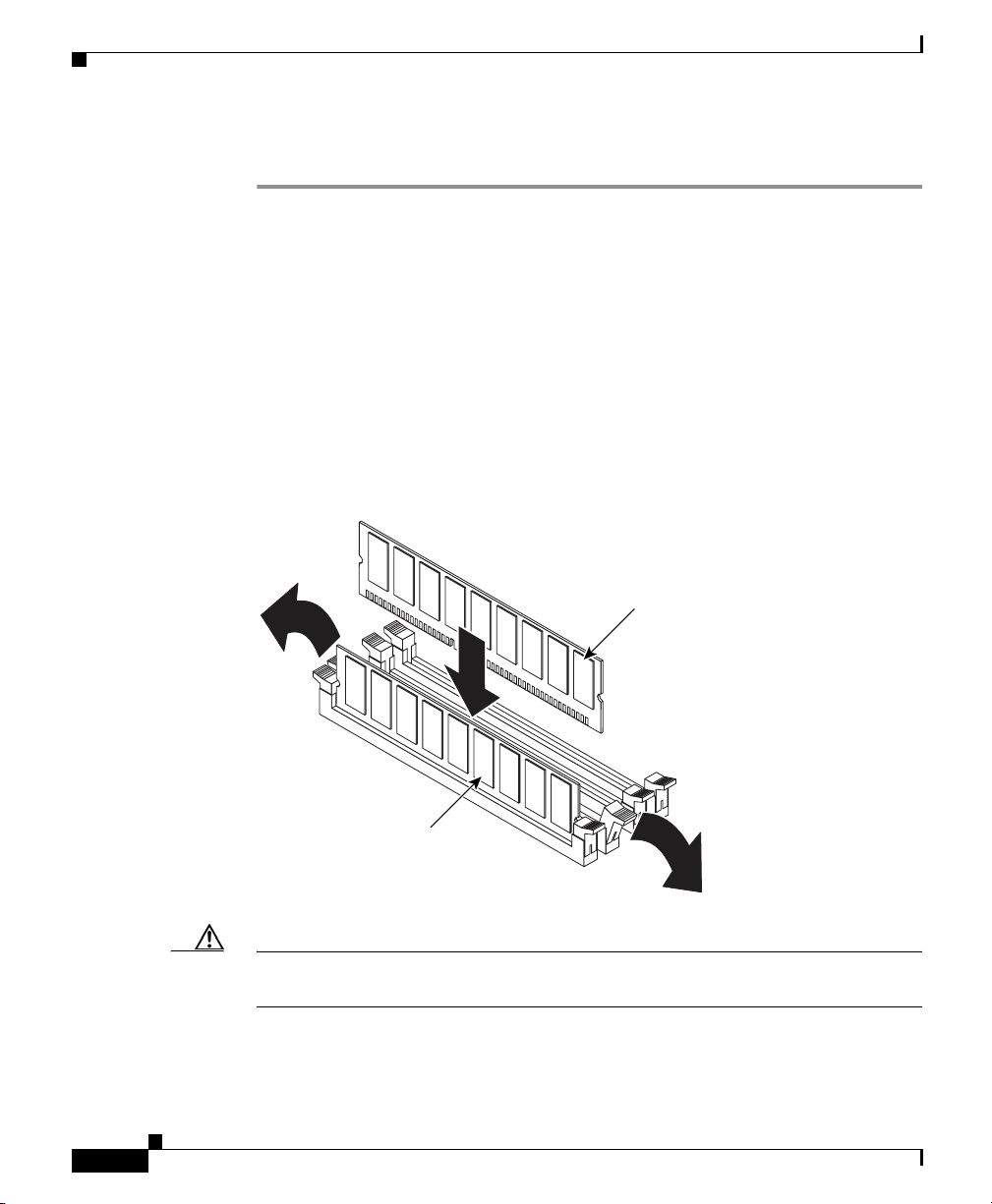
Installing DIMMs
Step 1 Review the safety information in the “Safety Guidelines” section on page 2-4.
Step 2 Power off the device and peripheral devices. Disconnect the power cord, and then
Step 3 Touch the static-protective package that contains the DIMM to any unpainted
Step 4 Install the DIMM:
Chapter 4 Installing Hardware Options
To install a DIMM, follow these steps:
disconnect all external cables. Remove the cover. (See the “Removing the Cover
and Bezel” section on page 4-1 for details.
metal surface on the device, and then remove the DIMM from the package.
a. Open the retaining clip on each end of the DIMM connector. Turn the DIMM
so that the pins align correctly with the connector. (See Figure 4-6.)
Figure 4-6 Installing a DIMM
DIMM 3
4-14
DIMM 4
131349
Caution To avoid breaking the retaining clips or damaging the DIMM connectors, open
and close the clips gently.
Cisco Wide Area Application Engine 511 and 611 Hardware Installation Guide
OL-7220-02
Page 87

Chapter 4 Installing Hardware Options
b. Insert the DIMM into the connector by aligning the DIMM edges with the
slots at each end of the DIMM connector. Firmly press the DIMM straight
down into the connector by applying pressure on both ends of the DIMM
simultaneously. Be sure that the retaining clips snap into the locked position
when the DIMM is firmly seated in the connector.
c. If a gap exists between the DIMM and the retaining clips, the DIMM has not
been properly installed. In this case, open the retaining clips and remove the
DIMM, and then reinsert the DIMM.
Step 5 If you have other options to install, do so now; otherwise, go to the “Completing
the Installation” section on page 4-17.
Working with Hard Disk Drives
This section describes how to install a hard disk drive in the Wide Area
Application Engine (WAE). The WAE-511 requires a Serial Advanced
Technology Attachment (SATA) hard disk drive. The SATA hard disk drive can be
replaced in the field.
Working with Hard Disk Drives
The WAE-611 supports two 1-inch (2.54-cm) slim 3.5-inch (8.89-cm) low voltage
differential (LVD) hard disk drives. The WAE-611 requires SCSI hard disk drives.
Note (To install the SCSI hard disk drives in the WAE-611, see the Installing Hard Disk
Drives in the Cisco Wide Area Application Engine 611 document that ships with
the following hard disk drive options: DISK-611SC-144GB= and
DISK-611SC-300GB= .)
Installing a Hard Disk Drive in the WAE-511
Note All hard disk drives being used in the WAE should have the same throughput
speed rating. Mixing hard disk drives with different speed ratings will cause all
hard disk drives to operate at the lower throughput speed.
Cisco Wide Area Application Engine 511 and 611 Hardware Installation Guide
OL-7220-02
4-15
Page 88

Working with Hard Disk Drives
Note If your device has only one hard disk drive, install it in the left drive bay.
Caution To maintain proper system cooling, do not operate the device for more than 10
minutes without either a hard disk drive or a filler panel installed in each bay.
To install a simple-swap SATA hard disk drive in a bay, follow these steps:
Step 1 Inspect the new drive for any signs of damage.
Step 2 Review the information in the “Safety Warnings” section on page 2-1, and the
“Safety Guidelines” section on page 2-4.
Step 3 Power down the device and peripheral devices, and disconnect the power cord and
all external cables.
Step 4 Press the release tabs on the bezel and pull the bezel away from the chassis. (See
Figure 4-2.)
Step 5 Install the hard disk drive in the bay:
a. Align the drive assembly (see Figure 4-7) with the guide rails in the bay.
Chapter 4 Installing Hardware Options
4-16
b. Gently push the drive assembly into the drive bay until the drive connects to
the backplane.
c. Check the hard disk drive status LED to verify that the hard disk drive is
operating properly.
If the amber hard disk drive status LED for a drive is lit continuously, that
individual drive is faulty and needs to be replaced. If the green hard disk drive
activity LED is flashing, the drive is being accessed.
Cisco Wide Area Application Engine 511 and 611 Hardware Installation Guide
OL-7220-02
Page 89
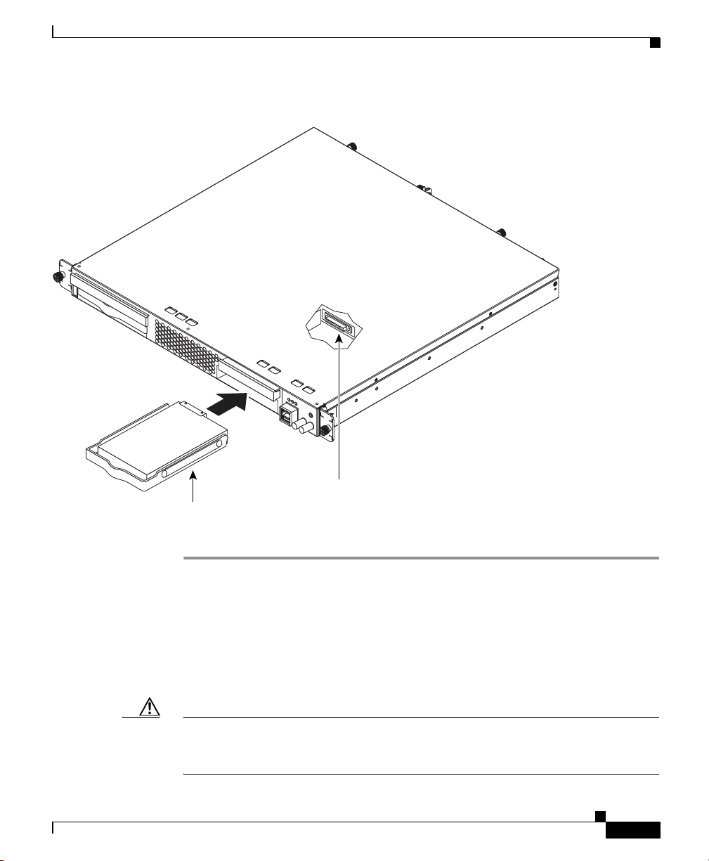
Chapter 4 Installing Hardware Options
Figure 4-7 Installing a SATA Hard Disk in the WAE-511
Completing the Installation
124005
SATA hard disk
Hard disk drive
drive connector
Completing the Installation
To complete your installation, reinstall the bezel, reinstall the cover, and
reconnect all cables that you disconnected earlier.
Caution To maintain proper cooling and airflow, install the cover before turning on the
device. Operating the device for extended periods (over 30 minutes) with the
cover removed might damage device components.
Cisco Wide Area Application Engine 511 and 611 Hardware Installation Guide
OL-7220-02
4-17
Page 90

Completing the Installation
To install the cover and bezel, follow these steps:
Step 1 Install the cover by placing it into position and sliding it forward, and then tighten
the captive screws (labeled 1 in Figure 4-8).
Caution Before sliding the cover forward, make sure that the cover will properly engage
the ledge at the front of the device.
Step 2 Install the bezel:
a. Align the hooks on the bottom of the bezel with the device.
b. Press the bezel toward the device until it clicks into place.
Figure 4-8 Installing the Cover
Chapter 4 Installing Hardware Options
1
4-18
115802
Cisco Wide Area Application Engine 511 and 611 Hardware Installation Guide
OL-7220-02
Page 91

Chapter 4 Installing Hardware Options
Step 3 Install the device in the rack. See the “Installing the Cisco Wide Area Application
Engine” section on page 3-2 for instructions.
Step 4 Connect all external cables and the power cord to the device, and then plug the
power cord into a properly grounded electrical outlet.
Completing the Installation
OL-7220-02
Cisco Wide Area Application Engine 511 and 611 Hardware Installation Guide
4-19
Page 92

Completing the Installation
Chapter 4 Installing Hardware Options
4-20
Cisco Wide Area Application Engine 511 and 611 Hardware Installation Guide
OL-7220-02
Page 93

Technical Specifications
This appendix describes the WAE models listed here:
Model Product Number
Wide Area Application Engine 511 WAE-511-K9(=)
Wide Area Application Engine 611 WAE-611-K9(=)
This appendix contains the following sections:
• Appliance Specifications, page A-1
• Adapter Specifications, page A-4
Appliance Specifications
APPENDIX
A
OL-7220-02
Note Your system software might not support all of the WAE-supported hardware
features.
Table A-1 summarizes the features and specifications for the WAE-511 and
WAE-611.
Cisco Wide Area Application Engine 511 and 611 Hardware Installation Guide
A-1
Page 94

Appendix A Technical Specifications
Appliance Specifications
Table A-1 Appliance Features and Specifications
Specification Description
Microprocessor
Memory
Expansion bays Two 3.5-in. (8.89-cm) slim-height bays for hard disk drives
Expansion slots Two 66-/100-MHz 64-bit PCI-X slots on the system board (half-length
Hard disk controller
Adapters
• WAE-511—One Intel 2.8-GHz Celeron 256-KB with level 2 cache and
multimedia extensions (MMX2) technology
• WAE-611—One Intel 3.0-GHz Pentium 4800 MHz with level 2 cache
and multimedia extensions (MMX2) technology
• WAE-511—One or two 512-MB SDRAM DIMMs
(MEM-WAE-512MB=)
• WAE-611—Two 1-GB SDRAM DIMMs (fixed configuration)
Regardless of the the amount of memory installed on your hardware device,
the amount of memory supported is regulated by the software version that
is installed:
• WAFS software supports up to 1 GB of memory.
• ACNS software supports up to 512 MB of memory. ACNS software
does not support additional memory over 512 MB.
full-height slots; one low profile and one full profile)
• WAE-511—Serial advanced technology attachment (SATA) controller
• WAE-611—Ultra320 SCSI controller
• 1-port Fibre Channel adapter
• 1-port MPEG A/V decoder adapter
Note The WAE-511 and WAE-611 support either the Fibre Channel
adapter or the MPEG A/V decoder adapter in PCI slot 1.
• Ultra320 SCSI adapter installed in PCI slot 2 (WAE-611 only)
• 4-port Ethernet inline network adapter
Power supply 1 AC-input
Dimensions
Cisco Wide Area Application Engine 511 and 611 Hardware Installation Guide
• Height: 1.75 in., 1 RU (44 mm)
• Depth: 20 in. (508 mm)
• Width: 16.94 in. (430 mm)
A-2
OL-7220-02
Page 95

Appendix A Technical Specifications
Appliance Specifications
Table A-1 Appliance Features and Specifications (continued)
Specification Description
Weight Maximum weight: 28 lb (12.7 kg) depending on your configuration
Electrical input
Ports
• Sine-wave input (47–63 Hz) required
• Input voltage low range:
–
Minimum: 100 VAC
–
Maximum: 127 VAC
• Input voltage high range:
–
Minimum: 200 VAC
–
Maximum: 240 VAC
• Input kilovolt-amperes (kVA), approximately:
–
Minimum: 0.20 kVA
–
Maximum: 0.45 kVA
• 1000BASE-TX, 100BASE-TX, 10BASE-T (dual) Ethernet ports
Tem p e r a t u r e
Heat Dissipation
Humidity
OL-7220-02
• Serial port
• 2 USB ports
• Ultra320 SCSI port (WAE-611 only)
• Fibre Channel port (on optional adapter)
• Audio/video ports (on optional adapter):
–
3 BNC connectors
–
2 mini-XLR connectors
• Operating: 50 to 95° F (10 to 35° C)
• Nonoperating: –40 to 140° F (–40 to +60° C)
• Minimum configuration: 307 Btu
• Maximum configuration: 850 Btu/hr (250 Watts)
• Operating: 8 to 80%
• Nonoperating: 8 to 80%
Cisco Wide Area Application Engine 511 and 611 Hardware Installation Guide
1
/hr (90 Watts
A-3
Page 96

Appendix A Technical Specifications
Adapter Specifications
Table A-1 Appliance Features and Specifications (continued)
Specification Description
Altitude Maximum altitude: 6998 ft (2133 m)
Acoustical noise
emissions
1. Btu = British thermal unit
• Sound power, idling: 6.5 bel maximum
• Sound power, operating: 6.5 bel maximum
Adapter Specifications
Table A-2 describes the Fibre Channel adapter specifications.
Table A-2 Fibre Channel Adapter Specifications
Fibre Channel adapter • Bus type: Fiber-optic media (shortwave 50-micron)
• Bus transfer rate: 2 gigabits per second (Gbps) maximum at half duplex
and 4 Gbps at full duplex
• Protocols: Supports FCP
1. FCP = Fibre Channel Protocol
1
-SCSI protocol
A-4
Table A-3 describes the MPEG A/V decoder adapter specifications.
Cisco Wide Area Application Engine 511 and 611 Hardware Installation Guide
OL-7220-02
Page 97

Appendix A Technical Specifications
Table A-3 MPEG A/V Decoder Adapter Specifications
Adapter Specifications
MPEG A/V decoder
adapter
1. S/N = signal-to-noise ratio
2. rms = root mean square
3. IRE = Institute of Radio Engineers
4. S/PDIF = Sony/Philips Digital Interface
5. PCM = pulse-coded modulation
6. p-p = peak to peak
7. THD = total harmonic distortion
Video specifications
• S/N:
• Frequency response: 0 to 4.0 MHz ± 2 dB
• Sync tip: 40 IRE
• Luma nonlinearity: 5%
• Audio specifications
• S/PDIF
–
–
–
• Analog
–
–
–
–
1
10 kHz to 4.2 MHz; Y: 65 dB rms2; Pb: 70 dB rms; Pr: 70 dB rms
3
± 4
4
PCM5 or compressed audio coding 3 (AC-3) bitstream out
75-ohm, 0.5-V p-p6 ± 20%
Rise and fall time: > 0.4 microseconds measured from 10 to 90%
Jumper-selectable balanced or unbalanced audio (balanced = +4
dBm)
Frequency response: 20 Hz to 22 kHz ± 0.5 dB
Reference level: 0.5-V p-p ± 10%
THD7+n:@20 Hz to 22 kHz < 0.5%
OL-7220-02
Table A-3 describes the inline network adapter technical and general
specifications.
Note The minimum software release required for the inline network adapter is
WAAS 4.0.7.
Cisco Wide Area Application Engine 511 and 611 Hardware Installation Guide
A-5
Page 98

Appendix A Technical Specifications
Adapter Specifications
Table A-4 Inline Network Adapter Specifications
Specification Description
Copper Gigabit Ethernet Specifications
IEEE standard Gigabit Ethernet, 1000BASE-T
Fast Ethernet, 100BASE-T
Ethernet, 10BASE-T
Full duplex and half duplex Supports both half-duplex and full-duplex operation in all
operating speeds
Autonegotiation Autonegotiates between full-duplex and half-duplex
operations and between 1000-Mbps, 100-Mbps, and
10-Mbps speeds
Data transfer rate 1000-Mbps, 100-Mbps, and 10-Mbps speeds per port in
half-duplex mode
2000-Mbps, 200-Mbps, and 20-Mbps speeds per port in
full-duplex mode
General Technical Specifications
Interface standard PCI v2.2 32/64 bit, 33/66 MHz
PCI-X v1.0 32/64 bit, 66/100/133 MHz
Size 6.6 in. x 4.2 in. (167.64 mm x 106.68 mm)
PCI connector Universal 64-bit connector
PCI voltage +12V (minimum 11.4V, maximum 12.6V)
+3.3V (minimum 3.0V, maximum 3.6V)
Weight 6.18 oz (175 grams)
Operating humidity 0
to 90 percent, noncondensing
Operating temperature 32° to –122° F (0° to 50° C)
Storage temperature –4° to –149° F (–20° to –65° C)
Cisco Wide Area Application Engine 511 and 611 Hardware Installation Guide
A-6
OL-7220-02
Page 99

Troubleshooting the System Hardware
If your system is not working as expected, begin troubleshooting using the
procedures in this appendix. This appendix guides you through some initial
checks and procedures that can solve basic system problems.
This appendix contains the following sections:
• Checking the Basics, page B-1
• Checking Connections and Switches, page B-2
Checking the Basics
To solve some basic system problems, follow these steps:
Step 1 Was an alert message issued by the system software?
Ye s . Check the component named in the alert message.
APPENDIX
B
OL-7220-02
No. Go to Step 2.
Step 2 Visually inspect the chassis. Is the system wet or damaged?
Ye s . Liquid spills, splashes, and excessive humidity can cause damage to the
system. If an external device such as an external drive gets wet, contact your
service representative for instructions. (See the “Obtaining Technical Assistance”
section on page xviii.)
Cisco Wide Area Application Engine 511 and 611 Hardware Installation Guide
B-1
Page 100

Checking Connections and Switches
If the chassis was dropped or damaged while being moved, you should check the
system to see if it functions properly. If an external device attached to the system
is dropped or damaged, contact your service representative for instructions. (See
the “Obtaining Technical Assistance” section on page xviii.)
No. Go to Step 3.
Step 3 Perform the steps in the “Checking Connections and Switches” section on
page B-2.
Is the problem resolved?
Ye s . The power to the system was faulty, or the connections to the system were
loose. You have fixed the problem.
No. Go to Step 4.
Step 4 Verify the settings in the system setup program. For details, refer to the software
configuration guide or user guide that corresponds to the version of software you
are running on your system.(See the “Related Documentation” section on
page xiii.)
Did the system complete the boot routine?
Ye s . The system configuration information was incorrect. You have fixed the
problem.
No. Call your service representative. (See the “Obtaining Technical Assistance”
section on page xviii.)
Appendix B Troubleshooting the System Hardware
Checking Connections and Switches
Improperly set switches and controls and loose or improperly connected cables
are the most likely source of problems for the chassis or other external equipment.
A quick check of all the switches, controls, and cable connections can easily
solve these problems. (See Figure 1-6 for the location of front panel controls
and indicators. See Figure 1-7 for the location of back panel connections on
the system.)
Cisco Wide Area Application Engine 511 and 611 Hardware Installation Guide
B-2
OL-7220-02
 Loading...