

Page 1

CHAPTER
Installation - Subtended Network
This section discusses installation procedures for adding subtended 6100s to a subtending host 6100.
In this manual, the term “subtending” refers to the host 6100 node, and “subtended” refers to the
downstream 6100 node in a subtended network.
All 6100s in a subtended network are installed in either a Digital Off-Hook (DOH) or a direct
connect configuration first. Then if the network is to be subtended, the procedures in this section
apply.
8
8.1 Cabling Configuration - Subtending
This section provides an illustration showing the cabling requirements for a subtended 6100.
Cisco 6100 Set Up and Installation Manual 8-1
Page 2
8 Installation - Subtended Network 78-5481-02 09/15/98
8.1.1 Cable Diagram - Subtending
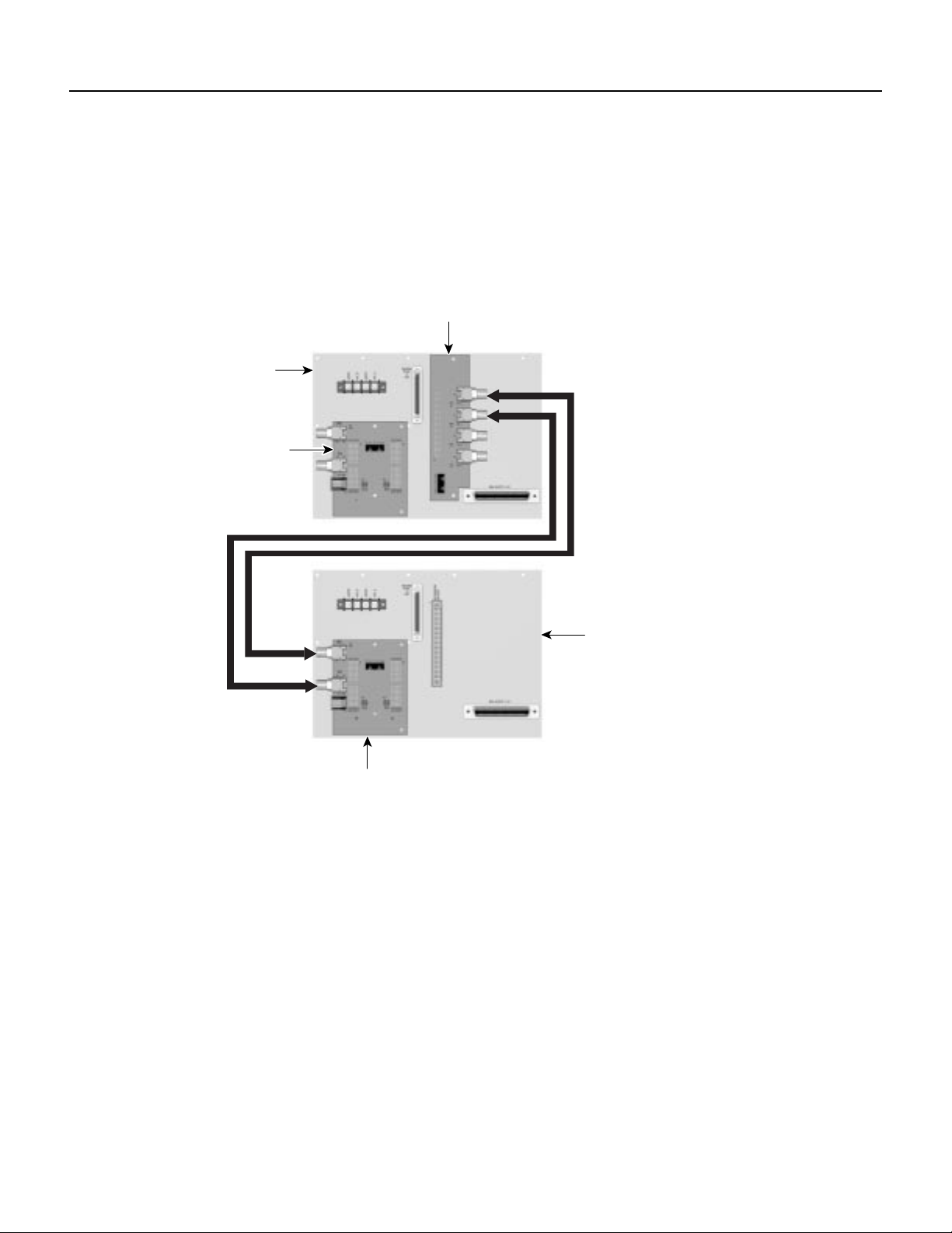
The following is an illustration of the basic cabling of a subtended 6100. Some connectors are not
used because they are specific to one of the other configurations of the 6100 or because they have
been reserved for future use.
Figure 8-1 Basic Cabling for Subtending
DS3 sudtending
card
Host MC
backplane
System I/O
card
Transmit
Receive
Receive
Transmit
System I/O
card
8.1.2 Cable Type - Subtending
The DS3 subtending I/O card on the subtending host 6100 connects directly to the system
I/O card on the subtended mode 6100. This connection is made with DS3 75-ohm coaxial cable.
Subtended MC
backplane
16833
Cisco 6100 Set Up and Installation Manual8-2
Page 3

78-5481-02 09/15/98 Installation - Subtended Network 8
8.2 Installation Procedures - Subtending
Thefollowingtableshowsachecklistofthe installation steps for subtended 6100s. Then subsequent
subsections, as noted in the last column of the Table 8-1, discuss each of the installation steps in
detail.
Table 8-1 Installation Steps Checklist
Check Installation Step
1. Install each of the Cisco 6100s in the system, including the subtended ones, with either DOH or direct
connect configuration as described in previous sections
2. Connect the DS3 subtending card to the MC backplane
3. Install the 2x DS3 subtending host module (STM) in slot 9 of the subtending host 6100 and the DS3
NI module in slot 10 of the subtended node MC
4. Cable the DS3 subtending I/O card on the subtending host MC to the system I/O card on the subtended
node MC
5. Complete the installation as described in the previous chapters, provision and test
MC=multiplexer chassis
NI=network interface
8.2.1 Installing the 6100s
Before connecting the subtended node 6100s to the subtending host 6100, install and cable all the
6100s, including the subtended ones, according to the procedures described in Chapters 5, 6, and 7
of this manual. Subtending is independent of the configuration style used. It works with both DOH
and direct connect.
Cisco 6100 Set Up and Installation Manual 8-3
Page 4
8 Installation - Subtended Network 78-5481-02 09/15/98
8.2.2 Connecting the DS3 Subtending Card
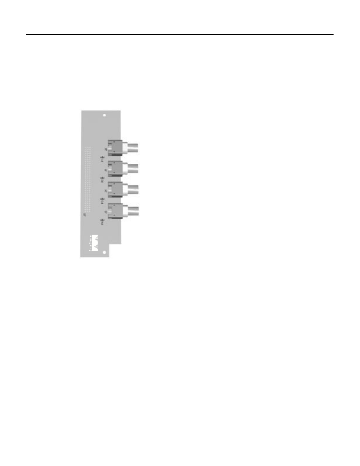
The DS3 subtending I/O card has two sets of DS3 75-ohm coaxial BNC connectors. Each set
consists of a transmit and a receive connector. The following figure illustrates the 2x DS3 subtend
card.
Figure 8-2 DS3 Subtend Card
Transmit
TX 1
Receive
RX 1
Transmit
TX 2
RX 2
Receive
16830
Cisco 6100 Set Up and Installation Manual8-4
Page 5

78-5481-02 09/15/98 Installation - Subtended Network 8
Connect the DS3 subtending I/O card to connector J48, a 96-pin DIN connector, on the subtending
host 6100 MC backplane. Refer to the Figure 8-3 for the location of these connectors.
Figure 8-3 DS3 Subtending Card Connector
System I/O
card
DS3 sudtending
card
16831
Cisco 6100 Set Up and Installation Manual 8-5
Page 6

8 Installation - Subtended Network 78-5481-02 09/15/98
Figure 8-4 DS3 Subtend Card - Standoffs
DS3 card
Existing
backplane
screw
DS3 card
standoff
16835
Existing
backplane
screw
DS3 card
standoff
See Figure 8-1 for an illustration of the cabling between the system I/O card on the subtended node
6100 and the DS3 subtend card on the subtended 6100.
Cisco 6100 Set Up and Installation Manual8-6
Page 7

78-5481-02 09/15/98 Installation - Subtended Network 8
8.2.3 Installing the DS3 Subtend Module
The DS3 NI module should be installed in slot 10 of the host 6100 before the ATU-Cs are installed
in the subtended node 6100. The DS3 subtend module should be installed in slot 9 of the subtending
host 6100. The following figure illustrates the front panel of the DS3 subtending host module. See
Table 9-6 for a description of the LEDs on the subtending host module.
Figure 8-5 DS3 Subtending Host Module
STATUS
ACTIVE
PORT 1
LOS
LOF
OCD
FERF
PORT 2
LOS
LOF
OCD
FERF
2X DS3 STM
16850
Caution
Proper electrostatic discharge (ESD) protection is required at all times when handling
modules. Installation and maintenance personnel should be properly grounded via ground straps to
eliminate the risk of ESD damage when handling modules. Modules are subject to ESD damage
upon removal from their anti-static shipment bag.
8.2.4 Cabling the System I/O Card to the DS3 Subtend Card
On the system I/O card are coaxial connections for DS3 cabling when a DS3 NI module is installed
in the 6100 or when a 6100 is subtended. See the “Connecting the DS3 Subtending Card”section for
more information on the NI modules. See Figure 7-9 for an illustration of the system I/O card. See
Figure 8-2 for an illustration of the DS3 subtend card.
Cable the system I/O card to the DS3 subtending I/O card as shown in Figure 8-1. The transmit
connector on the subtending I/O card cables to the receive connector on the subtended system I/O
card, and vice versa.
Cisco recommends that ferrite beads be added to the coaxial cables used to cable the DS3 subtend
card to the system I/O card to reduce the radiation/EMI susceptibility to high frequency noise
between 30 and 200 MHz.
Cisco 6100 Set Up and Installation Manual 8-7
Page 8

8 Installation - Subtended Network 78-5481-02 09/15/98
Using either the ferrite beads shipped with the DS3 NI module (type 43) or ones that use ferrite
material type 43 or 44 with an impedance of >200 ohms +/- 20% at 100 MHz, attach the beads close
to the transmit and receive BNC connectors on the DS3 subtend card. See Figure 8-2 for the location
of the BNC connectors.
If you are using thick type 734A coaxial cable, run the cable through the ferrite bead and clamp it
shut, as shown in Figure 8-6.
Figure 8-6 Thick Coaxial Cable through Ferrite Bead
Thick coaxial
cable
Ferrite
bead
16837
If you are using thin type 735A coaxial cable, run the cable through once, then loop it back through
the ferrite bead and clamp it shut, as shown in Figure 8-7.
Figure 8-7 Thin Coaxial Cable through Ferrite Bead
Thin coaxial
cable
Ferrite
bead
16836
Cisco 6100 Set Up and Installation Manual8-8
Page 9
78-5481-02 09/15/98 Installation - Subtended Network 8
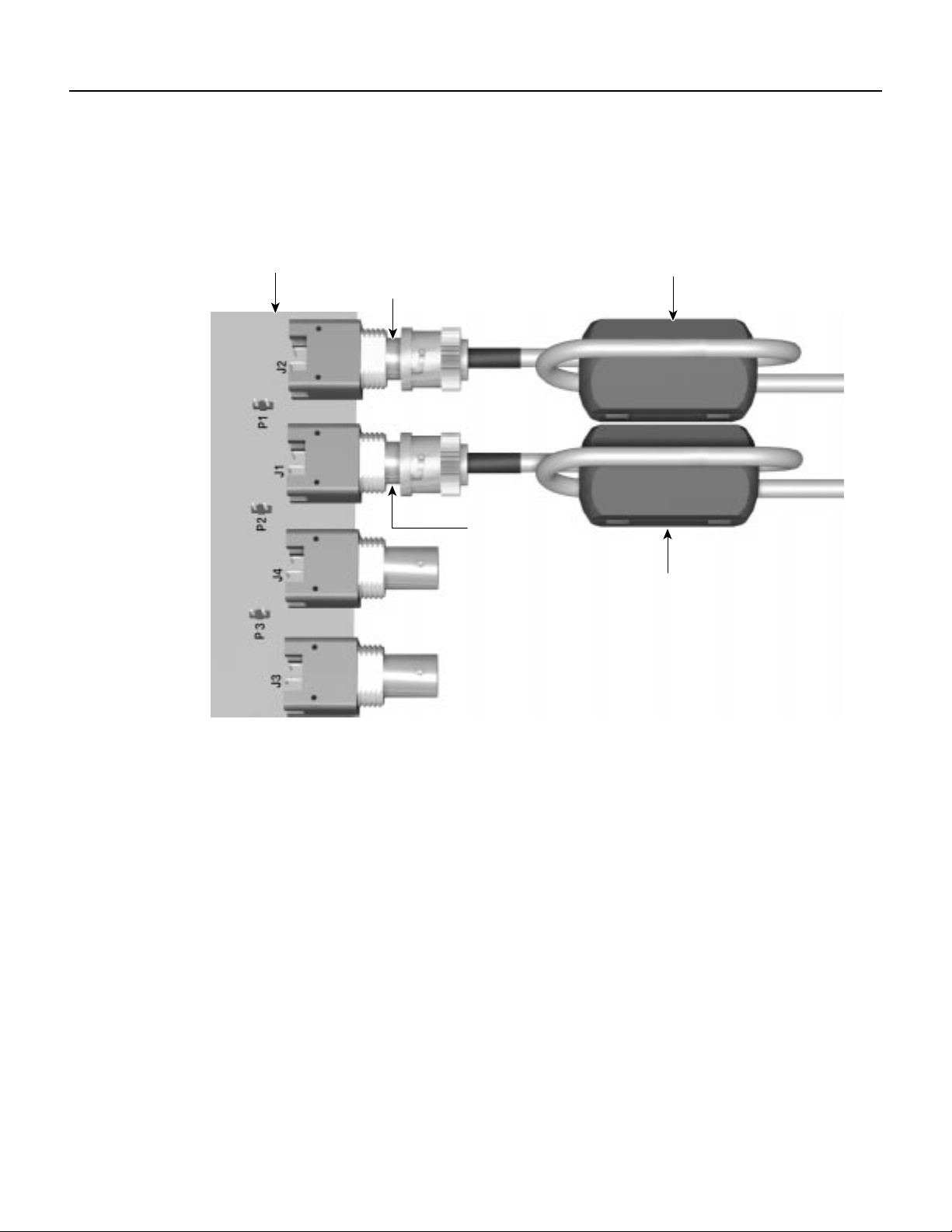
Figure 8-8 shows the ferrite beads on the coaxial cable close to the BNC connectors on the DS3
subtend card.
Figure 8-8 Ferrite Beads Close to BNC Connectors
System
I/O card
TX1
RX1
TX2
DS3 BNC
connector
Ferrite
bead
DS3 BNC
connector
Ferrite
bead
16839
8.2.5 Completing the Installation
When the system I/O card on the subtended node and the DS3 subtending I/O card on the subtending
host have been cabled and the DS3 subtending host module has been installed, complete the
installation, provisioning, and connectivity tests as described in previous chapters of this manual.
Cisco 6100 Set Up and Installation Manual 8-9
Page 10

8 Installation - Subtended Network 78-5481-02 09/15/98
8.3 Adding a DS3 Subtend Card
If you have an existing MC and you need to add a DS3 subtend card, you will need to remove two
of the screws from the backplane, add the standoffs shipped with the card, and reuse the two screws.
See the following figure for an illustration.
Figure 8-9 Adding Standoffs for a DS3 Card
DS3 card
Existing
backplane
screw
DS3 card
standoff
16835
Existing
backplane
screw
DS3 card
standoff
If you are installing the DS3 subtending I/O card on a new (2.2) MC, standoffs for mounting the card
are already in the card cage and the screws to mount the card are included in the package.
Cisco 6100 Set Up and Installation Manual8-10
Page 11

78-5481-02 09/15/98 Installation - Subtended Network 8
If you are installing the DS3 subtending I/O card on an older MC, you will need to add the standoffs
to mount the card. The following procedures describe howto add the standoffs. Figure 8-4 illustrates
the procedure.
1 Remove the two screws currently used to hold the backplane to the chassis above and below the
DS3 connector (J48).
2 Install the standoffs included with the DS3 I/O card in the same location as the screws you just
removed.
3 Connect the DS3 I/O card to connector J48 as shown in Figure 8-4.
4 Reuse the screws removed in Step 1 to hold the DS3 I/O card to the backplane.
Cisco 6100 Set Up and Installation Manual 8-11
Page 12

8 Installation - Subtended Network 78-5481-02 09/15/98
Cisco 6100 Set Up and Installation Manual8-12
 Loading...