

Page 1

Quick Start Guide
Cisco 600W Redundant Power System
Quick Start Guide with License and Warranty Information
1 Cisco 90-Day Limited Hardware Warranty Terms
2 Documents, Equipment, and Tools
3 Install the Chassis
4 Connect Cables
5 Power Up the Equipment
6 Obtaining Documentation
7 Obtaining Technical Assistance
8 Obtaining Additional Publications and Information
Page 2

1 Cisco 90-Day Limited Hardware Warranty Terms
There are special terms applicable to your hardware warranty and various services that you can use during the warranty period.
Y our formal Warranty Statement, including the warranty applicable to Cisco software, is included on the CD that accompanies
your Cisco product. Follow these steps to access and download the Cisco Information Packet and your warranty document from
the CD or from Cisco.com.
1. Launch your browser, and go to this URL:
http://www.cisco.com/univercd/cc/td/doc/es_inpck/cetrans.htm
The Warra nties and Licen se Agreements page appears.
2. To read the Cisco Information Packet, follow these steps:
a. Click the Information Packet Numbe r field, and make sure that the part number 78-5235-02 F0 is highlighted.
b. Select the language in which you would like to read the document.
c. Click Go.
The Cisco Limited Warranty and Software License page from the Information Packet a ppears.
d. Read the document online, or click the PDF icon to download and print the document in Adobe Portable Document
Format (PDF).
Note Y ou must have Adobe Acrobat Reader to view and print PDF files. You can download the reader from Adobe’s
website: http://www.adobe.com
3. To read translated an d localized warranty informati on about your product, follow these steps:
a. Enter this part number in the Warranty Document Number field:
78-5236-01C0
b. Select the language in which you would like to read the document.
c. Click Go.
The Cisco warranty page appears.
d. Review the document online, or click the PDF icon to download and print the document in Adobe Portable Document
Format (PDF).
You can also contact the Cisco service and support website for assistance:
http://www.cisco.com/en/US/support/
Duration of Hardware Warranty
Ninety (90) days.
Replacement, Repair, or Refund Policy for Hardware
Cisco or its service center will use commercially reasonable efforts to ship a replacement part within ten (10) working days after
receipt of a Return Materials Authorization (RMA) request. Actual delivery times can vary, depending on the customer location.
Cisco reserves the right to refund the purchase price as its exclusive warranty remedy.
2
Page 3

To Receive a Return Materials Authorization (RMA) Number
Contact the company from whom you purchased the product. If you purchased the product directly from Cisco, contact your
Cisco Sales and Service Representative.
Complete the information below, and keep it for reference:
Company product purchased from
Company telephone number
Product model number
Product serial number
Maintenance contract number
2 Documents, Equipment, and Tools
User Documentation
The documents described here are available online and on the documentation CD-ROM that you might have received with your
router. To be sure of obtaining the latest information, you should access the online documentation.
To print a document in its original page format , access the online documen t, and click the PDF ico n.
For more information about obtaining user documentation, see the “Obtaining Documentation” section on page 14.
To access online user documentation on Cisco.com (PDF and HTML formats):
Start on Cisco.com at http://www.cisco.com, and select Products & Services > Accessories > Power Supplies > Instructions and
Guides > Document type > Document.
Note You can also access user documents on the previo us Cisco website. On the C isco.co m h ome pag e, click on “Technical
Documentation on Cisco Connection Online” and follow the navigation paths described below.
To access user documentation on the Documentation CD-ROM (HTML format only) or on
Cisco Connection Online (CCO):
Start at Cisco Product Documentation and navigate to user documents using the paths described below.
Tip To navigate to the next higher level in the documentation hierarchy, click on CONTENTS in the navigation bar at the
top of each page.
Cisco RPS Documentation
Regulatory Compliance and Safety Information
The regulatory compliance and safety document provides essential safety information applicable to the Cisco RP S. This
document contains foreign-language translations of the safety warnings applicable to the Cisco RPS.
You can access this docu ment at Ci sco Product Documentation > Access Servers and Access Routers >
Cisco 600W Redundant Power System > Regulatory Compliance and Safety Information.
Hardware Installation Guide
A hardware installation guide provides specifications and additional instructions for in stalling and con necting the Cisco RPS.
You can access this docu ment at Ci sco Product Documentation > Access Servers and Access Routers >
Cisco 600W Redundant Pow er System > Cisco RPS Hardware Installation Guide.
3
Page 4

Related Hardware Installation
Additional hardware installation documents provide information about installing interconnection adapters in routers and about
rack-mounting the Cisco RPS.
You can access these d ocument sat Cisco Product Documentation > Acce ss Server s and Access Routers >
Cisco 600W Redundant Power System > Procedures for Spare Parts: Adapter Plates and Rack Brackets .
Release Notes
Release notes for the Cisco RPS provide information about the use of the Cisco RPS with various switches, hubs, and repeaters.
You can access this docu ment at Ci sco Product Documentation > Access Servers and Access Routers >
Cisco 600W Redundant Power System > Cisco Redundant Power System (RPS) Release Notes.
Items Included with Cisco RPS
The following items are supplied with each Cisco RPS except as noted:
• Rack-mount brackets with screws for 19-inch rack
• Two AC power cords
• (With Cisco RPS -CAB model only) Four 1-to-1 DC output cables, 22-pin to 18-pin, for quasi-redundant DC power for:
–
Cisco hubs and switches
–
Cisco 2600 series routers; Cisco 3620, Cisco 3640, and Cisco 3725 routers; and Cisco 4000 series routers
• Regulatory Compliance and Safety Information document
• Cisco Redundant Power System Quick Start Guide (this document)
Separately Orderable Items
One or more of the following cables are required for use with the Cisco RPS -NCAB model, which ships without DC output
cables. See Table 2 on page 8 for cable usage and ordering information.
• 1-to-1 DC output cable, 22-pin to 18-pin
• 1-to-1 DC output cable, 22-pin to 8-pin
• 2-to-1 Y cable, 22-pin to 18-pin or 22-pin to 8-pin
The following optional rack-mounting brackets can be ordered separately:
• Rack-mount brackets with screws for 23-inch and 24-inch racks
• Rack-mount brackets with screws for telco racks
An RPS adapter module is required for each of the following Cisco devices powered by a Cisco RPS: Cisco 2500 series routers;
Cisco 2600 series routers; Cisco 4000 series routers; Cisco 3620, Cisco 3640, and Cisco 3725 routers, and Cisco MC3810 series
concentrators. See Table 1 on page 8 for adapter plate usage and ordering information.
Items Not Included
Individual items in this list may be required for your application:
• Interface module to adapt the router or concentrator for use with the Cisco RPS
• Four screws for installing the chassis in a rack
• Phillips screwdriver
• Small blade screwdriver
• Cable ties for cable management
4
Page 5
3 Install the Chassis
k
B
k
Safety Information
For safety information you need to know before working on your Cisco RPS, see the Regulatory Compliance and Safety
Information document that accompanied this device.
Chassis Installation Methods
Warning
You can set the chassis on a desktop or install i t in a rack. See the appli cable instructions following.
Caution Y our chassis installation must allow unrestricted airflow for chassis cooling. For installation on a desktop, be sure
Only trained and qualified personnel should be allowed to install or replace this equipm ent. To see translations of
the warnings that appear in this publication, refer to the Regulatory Compliance and Safety Info rm ation document
that accompanied this device.
to install the rubber feet; they provide clearance for cooling airflow.
Installation in a Rack
You can install the Cisco RPS in a 19-inch, 23-inch, or 24-inch ra ck with the following chassis orientations:
• In a 19-, 23-, or 24-inch rack:
–
Brackets attached at the front of the chassis with the front panel facing forward
–
Brackets attached at the rear of the chassis with the rear panel facing forward
• In a center-mount telco rack:
–
Brackets attached at the front of the chassis with the front panel facing forward
–
Brackets attached at the rear of the chassis with the rear panel facing forward
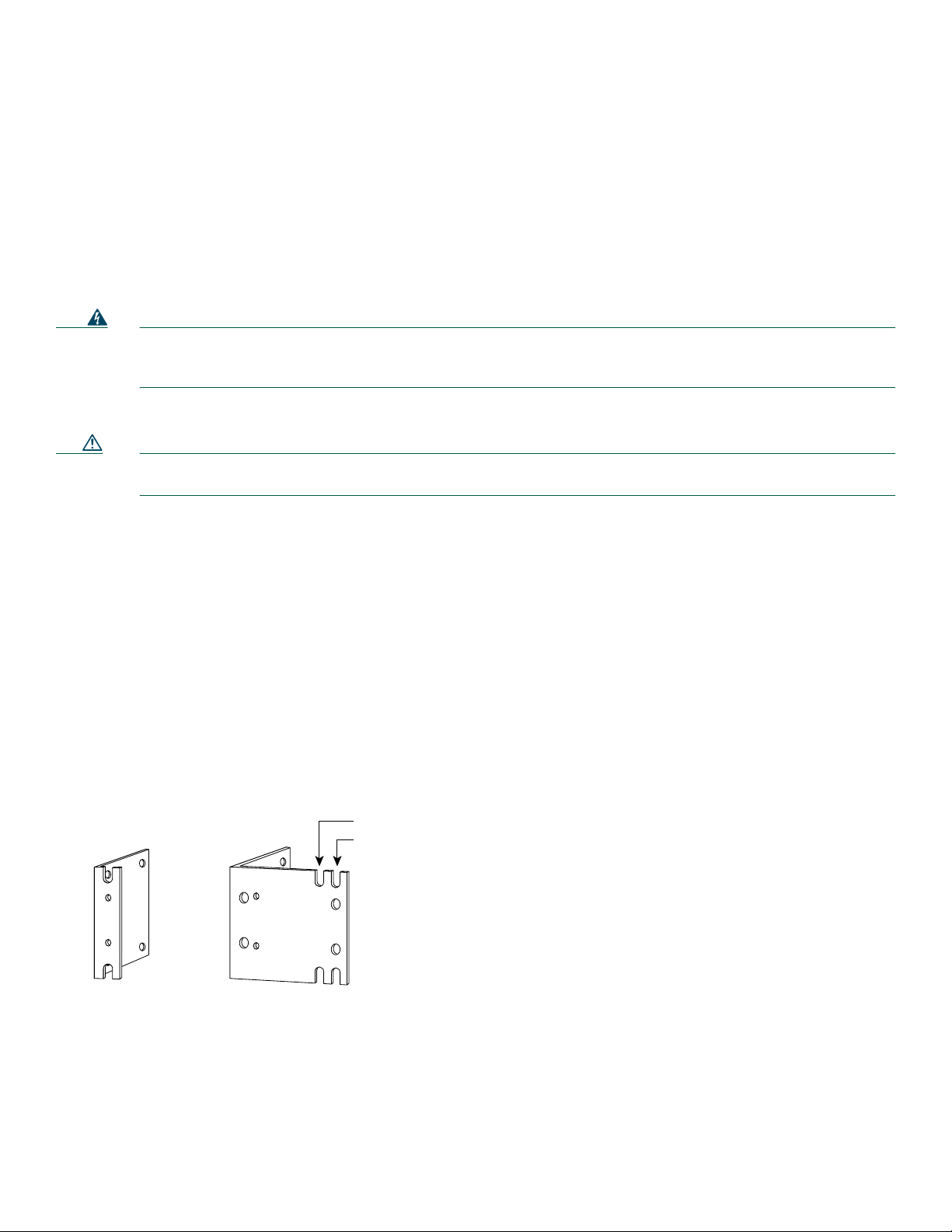
The rack-mounting brackets are shown in Figure 1 and Figure 2.
Figure 1 Brackets for 19-, 23-, and 24-Inch Rack-Mounting
Use with 23-inch rac
Use with 24-inch rac
H9695
racket for 19-inch rack
Bracket for 23- and 24-inch rack
5
Page 6
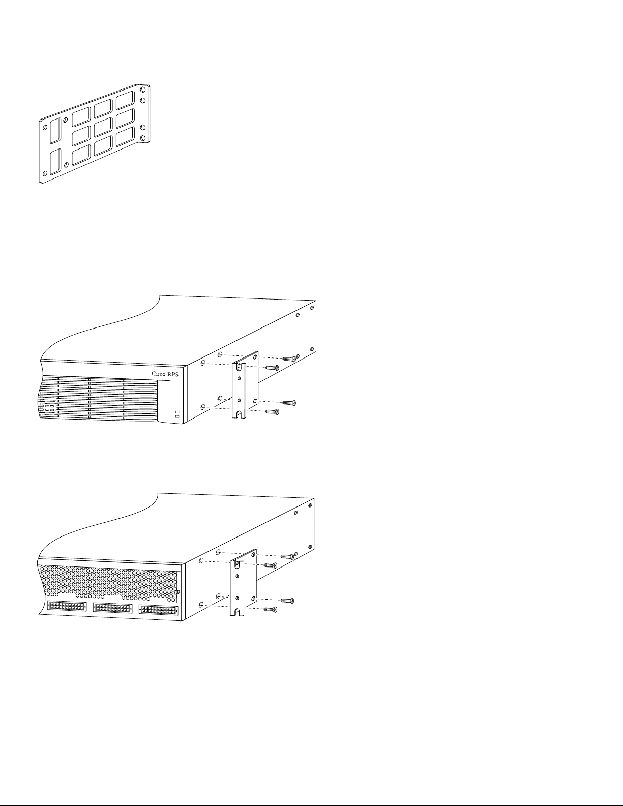
Figure 2 Brackets for Telc o Rack-Mounting
N
DC STATUS
12
3
4
H9697
10254
Attaching Brackets
Attach the mounting brackets to the chassis as shown in Figure 3, Figure 4, or Figure 5, using the screws provided in the bracket
kit. Use a number 2 Phillips screwdriver to install the bracket screws.
Figure 3 Bracket Attachment for 19-, 23-, or 24-Inch Rack with Front Panel Forward
H9696
FAN
TEMP
ote: The second bracket attaches to the other side of the chassis.
Figure 4 Bracket Attachment for 19-, 23-, or 24-Inch Rack with Rear Panel Forw ard
DC OUTPUT 2
Note: The second bracket attaches to the other side of the chassis.
DC OUTPUT 3
DC OUTPUT 4
6
Page 7

Figure 5 Bracket Attachment for Telco Rack wit h Rear Panel Forward
N
The brackets can also be installed with the Cisco RPS front panel forward.
11540
DC OUTPUT 3
ote: The second bracket attaches to the other side of the chassis.
DC OUTPUT 4
Installing the Chassis in a Rack
Install the chassis in the rack . Rack-mount ing screws are not provided with the router. Use two screws for each side (supplied
with the rack).
Installation on a Desktop
For desktop installation, attach the rubber feet from the accessory kit in the round re cesses on the chassis bottom.
Caution If you place the Cisco RPS on a desktop, do not place anything that weighs more than 10 lb (4.5 kg) on top of the
chassis.
4 Connect Cables
Caution The Cisco RPS is power-factor-corrected to comply with certain International Electrotechnical Commission (IEC)
standards. Do not connect the Cisco RPS to an uninterruptible power supply (UPS) that has not been tested a nd
designed for power-factor -corrected power systems. Do not connect the Cisco RPS to a ferro-resonant transformer.
If you do either of these things, you could damage the Cisco RPS.
Connection Options and Requirements
RPS Interface Modules
To connect to a Ci sco RPS, Cisco router s and Cisc o MC3810 se ries concentr ators must be equi pped with an RPS in terface
module. Interface modules are prov ided with installa tion instructions.
The FastHub 400 series hubs, Cisco 1516M hub (HP 10BASE-T Hub-16M), Catalyst 1900 and Ca talyst 2820 series switches,
and Catalyst 2900 series and Catalyst 3500 series XL switches ship with an RPS connector and do not require an RPS adapter
module.
Table 1 summarizes the RPS interface module requirements.
7
Page 8

Table 1 RPS Interface Modules
Powered Device RPS Interface Module
Cisco 2500 series, Cisco MC3810 ACS-2500RPS=
Cisco 2600 series ACS-2600RPS=
Cisco 3620 ACS-3620RPS=
Cisco 3640 ACS-3640RPS=
Cisco 3725 ACS-3725RPS=
Cisco 4000 series ACS-4000RPS=
Connection Methods and Cables
Table 2 summarizes the redundancy options and cable requirements for the various external devices that can be supported by
the Cisco RPS.
Table 2 Redundancy Options and Cable Requirements
Cable Order
Redundancy Configuration DC-Powered Device Cable Description
Quasi-redundant
(Routers, hubs, and
switches)
Cisco 1516M hub (HP 10BASE-T Hub-16M)
FastHub 400 series hubs
Catalyst 1900 series, Ca talyst 2820 series,
One-to-one cable,
22-pin to 18-pin,
4 ft. (1.22 m)
1
Catalyst 2900 seri es and Catalyst 3500 series XL
switches
Cisco 2600 series and Cisco 4000 series routers
Cisco 3620, Cisco 3640, and Cisco 3725 routers
Fully redundant
(Routers only)
Redundant with reboot
2
(Hubs and switches only)
Cisco 2500 series routers and access servers
Cisco MC3810 multiservice concentrators
Cisco 2600 series and Cisco 4000 series routers
Cisco 3620, Cisco 3640, and Cisco 3725 routers
Cisco 2500 series routers and access servers
Cisco MC3810 multiservice concentrators
FastHub 400 series hubs
Catalyst 1900 series, Ca talyst 2820 series,
Catalyst 2900 seri es and Catalyst 3500 series XL
One-to-one cable,
22-pin to 8-pin,
4 ft. (1.22 m)
1
Two-to-one cable,
22-pin to 18-pin,
4 ft. (1.22 m)
1
Two-to-one cable,
22-pin to 8-pin,
4 ft. (1.22 m)
1
One-to-one cable,
22-pin to 18-pin,
4 ft. (1.22 m)
1
switches
1. The cables come in only one length. Custom cable-lengths are not available. Excessive voltage drop and marginal or failed operation can occur with
cables of different lengths. Use of cables other than the ones listed can cause damage to the Cisco RPS or external device.
2. This configuration is not recommended due to the 30 -second reboot and downtime.
Number
CAB-RPS-2218=
CAB-RPS-2208=
CAB-RPSY-2218=
CAB-RPSY-2208=
CAB-RPS-2218=
The connection options are shown in the following figures:
• Quasi-redundant—Figure 6. The AC input to the Cisco RPS is fully redundant, but the DC output to the external devices
is not.
Note Quasi-redundant is the only recommended configuration for Cisco switches and hubs.
8
Page 9

• Fully redundant—Figure 7. The power source is fully redundan t because there ar e two AC input mo dules and two DC
150W or less
C
C
output power modules connected to each external device. If any power module fails, there is a full backup.
Note This configuration is not supported for switches and hubs.
• Redundant with reboot—Figure 8. In normal operation, the hub or switch is powered directly by its AC power connection.
If the internal power system of the hub or switch fails, the device powers down for about 30 seconds until the Cisco RPS
begins supplying power.
Note Redundancy with reboot works for the following devices only: FastHub 400 series hubs, Catalyst 1900 series and
Catalyst 2820 switches, and Catalyst 2900 series and Catalyst 3500 series XL switches.
• Mixed quasi-redundant and fully redundant—Figure 9. Three external devices can be powered, with two in
quasi-redundant mode and one in fully redundant mode.
Figure 6 Quasi-Redundant Configuration
AC input
DC
isco RPS
DC output
DC
External devices
DC
Figure 7 Fully Redundant Configuration
DC
isco RPS
DC
DC
AC
AC
AC
NM3998
DC
AC input
AC
11962
DC
DC output
9
Page 10

Figure 8 Redundant-with-Reboot Configuration
C
Quasi-RedundantFully redundant
C
AC input
DC
isco RPS
DC output
DC
AC power cords
AC power strip
Figure 9 Mixed Configuration
DC
AC
AC
AC
12052
DC
External devices
150W or less
AC input
AC
11681
isco RPS
DC
DC output
DC
DC
DC
Cable Connection Procedures
Before connecting to external devices, read the power warnings below. Cisco recommends that you disconnect all power before
beginning.
Note You can con nect an additi onal external device to a Cisco RPS that is already powered up without interrupting power
to the Cisco RPS or to any other connected external devices. Be sure to connect your cabl e to the Cisco RPS first and
then to the external device. However, in a redundant-with-reboot configuration, to ensure proper operation, you must
power up the switch or hub before powering up the Cisco RPS. Therefore, always connect the switch to AC before you
connect it to the Cisco RPS. Failure to follow the proper power-up sequence can result in incorrect LED displays.
10
Page 11

Warning
11537
connector
switch
Attach only the Cisco RPS (model PWR600-AC-RPS) to the RPS receptacle. To see translations of the warnings that
appear in this publication, refer to the Regulatory Compliance and Safety Information docu ment that accompanied
this device.
Warning
Before performing any of the following procedures, ensure that power is removed from the DC circuit. To ensure
that all power is OFF, locate the circuit breaker on the panel board that services the DC circuit, switch the circuit
breaker to the OFF position, and tape the switch handle of the circuit breaker in the OFF position. To see
translations of the warnings that appear in this publication, refer to the Regulatory Compliance and Safety
Information document that accompanied this device.
Warning
Before working on a system that has an on/off switch, turn OFF the power and unplug the power cord. To see
translations of the warnings that appear in this publication, refer to the Regulatory Compliance and Safety
Information document that accompanied this device.
Warning
This unit might have more than one power cord. To reduce the risk of electric shock, disconnect the two power
supply cords before servicing the unit. To see translations of the warnings that appear in this publication, refer to
the Regulatory Compliance and Safety Information document that accompanied this device.
To connect an external hub, switch, rou ter, or concentrator to a Cisco RPS, perform the following steps:
Step 1 Disconnect the AC power cord on a hub or switch; turn the power switch to the OFF position on a router or
concentrator.
Step 2 Connect the DC-output end of the cable to the RPS con nector on the rear panel of th e hub, switch, router, or
concentrator. The DC-output end of the RPS cable has either 8 or 18 pins in the connector. (For connector locations,
see Figure 10 through Figure 13.)
Figure 10 RPS Connector Location on a Cisco Hub (Typical)
AC power
connector
Cisco RPS
Serial port
RS-232
Reset
11
Page 12
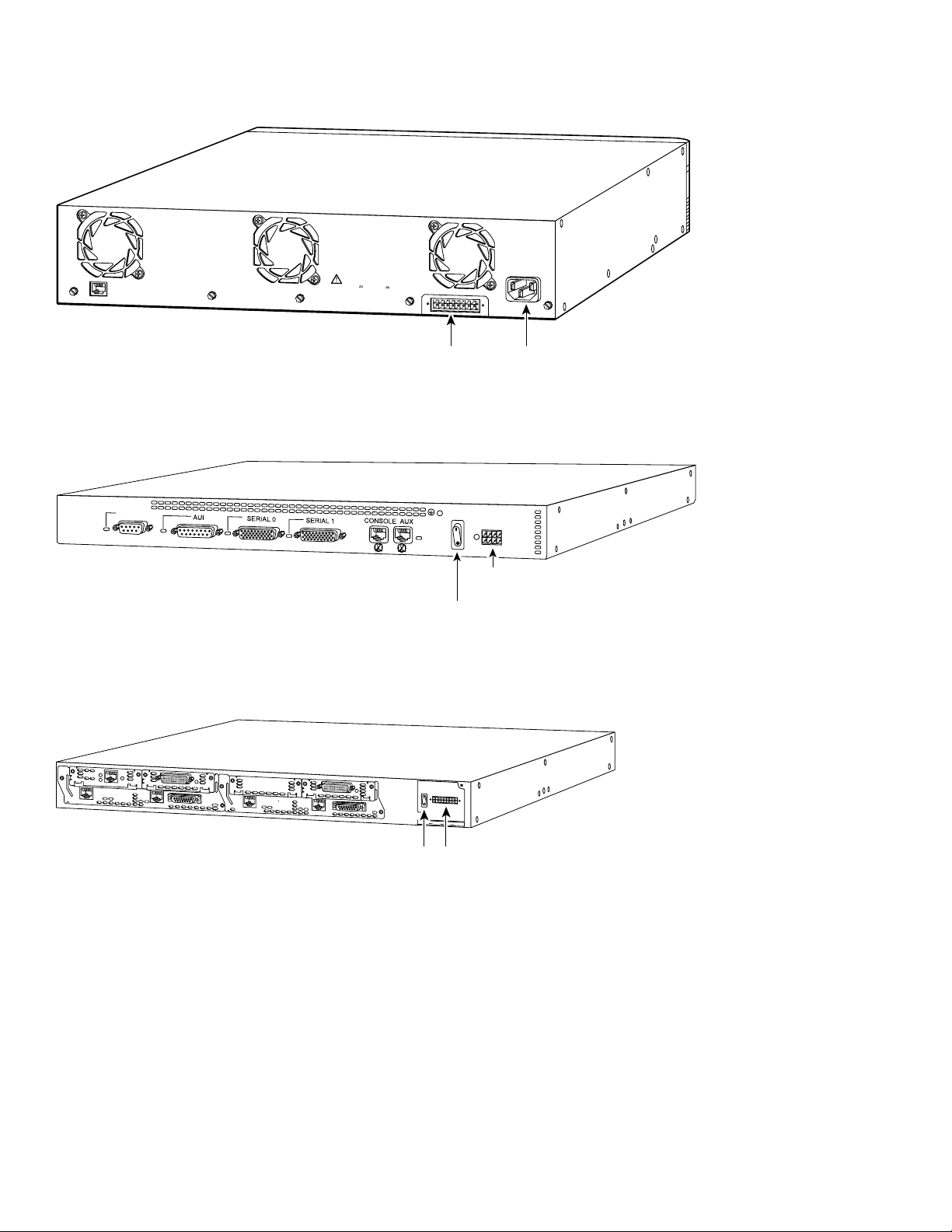
Figure 11 RPS Connector Location on a Cisco Switch (Typical)
H9425
12276
connector
RATING
~
100-120/200-240V
2.0A/1.0A 50-60HZ
AC power
connector
CONSOLE
DC INPUTS FOR REMOTE
POWER SUPPLY
SPECIFIED IN MANUAL.
+5V @24A, +12V @1.0A
DC INPUT
Cisco RPS
connector
Figure 12 RPS 8-Pin Connector Location on a Cisco Router or Concentrator (Typical)
Input: 100-240VAC
TOKEN RING
Freq: 50/60 Hz
Current: 1.2-0.6A
Watts: 40W
Cisco RPS
connector
On/off
switch
Figure 13 RPS 18-Pin Connector Location on a Cisco Router (Typical)
28732
12
2E
W1
2W
B1
NT1
BRI
B2
SEE MANUAL BEFORE INSTALLATION
ETHERNET 1
1
NT1
ACT
LNK
ACT
LNK
ETHERNET 0
2E
WO
ACT
W1
DO NOT INSTALL WAN INTERFACE
2W
CARDS WITH POWER APPLIED
SERIAL
AUI
EN
ETHERNET 1
ACT
LNK
ACT
ETH 1
LNK
ETHERNET 0
ACT
SERIAL
AUI
EN
0
On/off
switch
DC INPUT FOR USE WITH CISCO RPS
+5V–––14A, +12V–– –5A, -12V–––3A
Cisco
RPS
Page 13
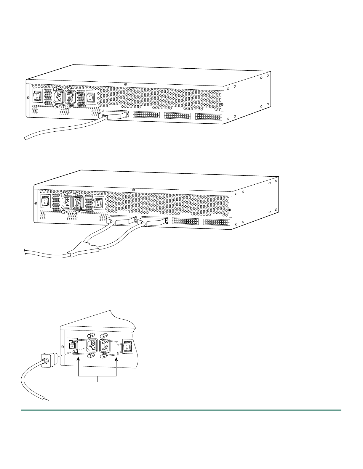
Step 3 Connect the DC-input end of the cable to a Cisco RPS rear-panel connector as shown in Figure 14 or Figure 15.
88107
29092
Figure 14 Connecting a One-to-One Cable to a Cisco RPS for Quasi-Redundant Power
AC INPUT 1
100-200 V~ 50/60 Hz
10-5 A 1000 W
AC INPUT 2
100-200 V~ 50/60 Hz
10-5 A 1000 W
DC OUTPUT 1
DC OUTPUT 2
DC OUTPUT 3
DC OUTPUT 4
88108
Figure 15 Connecting a Two-to-One Y-Cable to a Cisco RPS for Fully Redundant Power
AC INPUT 1
100-200 V~ 50/60 Hz
10-5 A 1000 W
AC INPUT 2
100-200 V~ 50/60 Hz
10-5 A 1000 W
DC OUTPUT 1
DC OUTPUT 2
DC OUTPUT 3
DC OUTPUT 4
Step 4 On the Cisco RPS rear panel, connect one or two AC power cables. A single AC power cable can go into either AC
connector. Two AC power cables provide parallel AC power sources. Use the cable locks on the Cisco RPS to lock the
cables in place. (See Figure 16.)
Figure 16 Connecting AC Power Cables to the Cisco RPS
Cable locks
13
Page 14

5 Power Up the Equipment
29091
P
Step 1 If you are using the redundant-with-reboot configuration (not recommended), power up the switch by connecting the
AC power cord of the hub or switch to an AC power outlet.
Note If you use the redundant-with-reboot configuration, it is important to power up the hub or switch before powering up
the Cisco RPS to e nsure correct o peration. If the Cisco RPS powers up first, the LEDs might not indicate the actual
state.
Step 2 Plug the other end of the Cisco RPS AC power cable into an AC power outlet.
Step 3 Power up the Cisco RPS. There is a separate power switch for each AC input power source. Make sure that the power
switch is on for each AC power source used. (See Figure 17.)
Figure 17 Powering Up the Cisco RPS
ower switch
The Cisco RPS provides power in 10 to 15 seconds. The Cisco RPS is working properly when all its front-panel LEDs are solid
green. If the external device does not power up, refer to troubleshooting section of the Cisco Redundant Power System
Hardware Installation Guide on Cisco.com.
6 Obtaining Documentation
Cisco provides several ways to obtain documentation, technical assistance, and other technical resources. These sections explain
how to obtain technical information from Cisco Systems.
Cisco.com
You can access the most current Cisco documentation on the World Wide Web at this URL:
http://www.cisco.com/univercd/home/home.htm
You can access the C isco website at this URL:
http://www.cisco.com
International Cisco websites can be accessed from this URL:
http://www.cisco.com/public/countries_languages.shtml
14
Page 15

Documentation CD-ROM
Cisco documentation and additional literature are available in a Cisco Documentation CD-ROM packag e, which may have
shipped with your product. The Documentation CD-ROM is updated monthly and may be more current than printed
documentation. The CD-ROM package is available as a single unit or through an annual subscription.
Registered Cisco.com users can order the Documentation CD-ROM (product number DOC-CONDOCCD=) through the online
Subscription Store:
http://www.cisco.com/go/subscription
Ordering Documentation
You can find instructions for ordering docu mentation at this URL:
http://www.cisco.com/univercd/cc/td/doc/es_inpck/pdi.htm
You can order Cisco documentation i n these ways:
• Registered Cisco.com users (Cisco direct customers) can order Cisco product documentation from the Networking Products
MarketPlace:
http://www.cisco.com/en/US/partner/ordering/index.shtml
• Registered Cisco.com users can order the Documentation CD-ROM (Customer Order Number DOC-CONDOCCD=)
through the online Subscription Store:
http://www.cisco.com/go/subscription
• Nonregistered Cisco.com users can order documentation through a local account representative by calling Cisco Systems
Corporate Headquarters (California, U.S.A.) at 408 526-7208 or, elsewhere in North America, by calling 800 553-NETS
(6387).
Documentation Feedback
You can submit comments electronically on Cisco.com. On the Cisco Documen tation home page, click Feedba ck at the top of
the page.
You can email your comments to b ug-doc@cisco.com.
You can submit your comments by mail by using the response card behi nd the front cover of your document or by writing to
the following address:
Cisco Systems
Attn: Customer Document Ordering
170 West Tasman Drive
San Jose, CA 95134-9883
We appreciate your co mments.
7 Obtaining Technical Assistance
Cisco provides Cisco.com, which includes the Cisco Technical Assistance Center (TAC) Website, as a starting point for all
technical assistance. Customers and partners can obtain online documentation, troubleshooting tips, and sample configurations
from the Cisco TAC website. Cisco.com registered users have complete access to the technical support resources on the Cisco
TAC w ebsite, including TAC tools and utilities.
Cisco.com
Cisco.com offers a suite of interactive, networked services that let you access Cisco information, networking solutions, services,
programs, and resources at any time, from anywhere in the world.
Cisco.com provides a broad range of features and services to help you with these tasks:
• Streamline business processes and improve productivity
15
Page 16

• Resolve technical issues with online support
• Download and test software packages
• Order Cisco learning materials and merchandise
• Register for online skill assessment, training, and certification programs
To obtain customized information and service, you can self-register on Cisco.com at this URL:
http://www.cisco.com
Technical Assistance Center
The Cisco TAC is avail able to all customers who need technical assistance with a Cisco product, technology, or solution. Two
levels of support are available: the Cisco TAC website and the Cisco TAC Escalation Center. The avenue of support that you
choose depends on the priority of the problem and the conditions stated in service contracts, when applicable.
We ca tegorize Cisco TAC inquiries according to urgency:
• Priority level 4 (P4)—You need in formation or assistance concerning Cisco product capabilities, product installation, or
basic product configuration.
• Priority level 3 (P3)—Your netwo rk performance is degraded. Netw ork functionality is noticeabl y impaired, but most
business operations continue.
• Priority level 2 (P2)—Your productio n network is severely degraded, affecting significant aspects of business operations.
No workaround is available.
• Priority level 1 (P1)—Your production network is down, and a critical impact to business operations will occur if service is
not restored quickly. No work around is available.
Cisco TAC Website
You can use the Cisco TAC website to resolve P3 and P4 issues yourself, saving both cost and time. The site provides
around-the-clock access to online tools, knowledge bases, and software. To access the Cisco TAC website, go to this URL:
http://www.cisco.com/tac
All customers, partners, and resellers who have a valid Cisco service contract have complete access to the technical support
resources on the Cisco TAC website. Some services on the Cisco TAC website require a Cisco.com login ID and password. If
you have a valid service contract but do not have a login ID or passwo rd, go to this URL to register:
http://tools.cisco.com/RPF/register/register.do
If you are a Cisco.com registered user, and you cannot resolve your technical issues by using the Cisco TAC website, you can
open a case online at this URL:
http://www.cisco.com/en/US/support/index.html
If you have Internet access, we recommend that you open P3 and P4 cases through the Cisco TAC website so that you can
describe the situation in your own words and attach any necessary files.
Cisco TAC Escalation Center
The Cisco TAC Escalation Center addresses priority level 1 or priority level 2 issues. These classifications are assigned when
severe network degradation significantly impacts business operations. When you contact the TAC Escalation Center with a P1
or P2 problem, a Cisco TAC engineer automatically opens a case.
To obtain a directory of toll-free Cisco TAC telephone numbers for your country, go to this URL:
http://www.cisco.com/warp/public/687/Directory/DirTAC.shtml
Before calling, please check with your network operations center to determine the level of Cisco support services to which your
company is entitled: for example, SMARTnet, SMARTnet Onsite, or Network Supported Accounts (NSA). When you call the
center, please have available your service a greement number and your product serial number.
16
Page 17

8 Obtaining Additional Publications and Information
Information about Cisco products, technologies, and network solutions is available from various online and printed sources.
• The Cisco Product Catalog describes the networking products offered by Cisco Systems as well as ordering and customer
support services. Access the Cisco Product Catalog at this URL:
http://www.cisco.com/en/US/products/products_catalog_l inks_launch.html
• Cisco Press publishes a wide range of networking publications. Cisco suggests these titles for new and experienced users:
Internetworking Terms and Acronyms Dictionary, Internetworking Technology Handbook, Internetworking
Troubleshooting Guide, and the Internetworking Design Guide. For current Cisco Press titles and other information, go to
Cisco Press online at this URL:
http://www.ciscopress.com
• Packet magazine is the Cisco monthly periodical that provides industry professionals with the latest information about the
field of networking. You can access Packet magazine at this URL:
http://www.cisco.com/en/US/about/ac123/ac114/ab out_cisco_packet_magazine.html
• iQ Magazine is the Cisco monthly periodical that provides business leaders and decision makers with the latest information
about the networking industry. You can access iQ Magazine at this URL:
http://business.cisco.com/prod/tree.taf%3fasset_id=44699&public_view=true&kbns=1.html
• Internet Protocol Journal is a quarterly journal published by Cisco Systems for engineering professionals involved in the
design, development, and operation of public and private internets and intranets. You can access the Internet Protocol
Journal at this URL:
http://www.cisco.com/en/US/about/ac123/ac147/ab out_cisco_the_i nternet_protocol_journal.html
• Tra ining—Cisco offers w orld-class networki ng training, with current offerings in network training listed at this URL:
http://www.cisco.com/en/US/learning/le31/learning _recommended_training_list.html
17
Page 18

18
Page 19

19
Page 20

Corporate Headquarters
r,
,
t
o
Cisco Systems, Inc.
170 West Tasman Drive
San Jose, CA 95134-1706
USA
www.cisco.com
Tel: 408 526-4000
800 553-NETS (6387)
Fax: 408 526-4100
European Headquarters
Cisco Systems International BV
Haarlerbergpark
Haarlerbergweg 13-19
1101 CH Amsterdam
The Netherlands
www-europe.cisco.com
Tel: 31 0 20 357 1000
Fax: 31 0 20 357 1100
Americas Headquarters
Cisco Systems, Inc.
170 West Tasman Drive
San Jose, CA 95134-1706
USA
www.cisco.com
Tel: 408 526-7660
Fax: 408 527-0883
Asia Pacific Headquarters
Cisco Systems, Inc.
Capital Tower
168 Robinson Road
#22-01 to #29-01
Singapore 068912
www.cisco.com
Tel: +65 6317 7777
Fax: +65 6317 7799
Cisco Systems has more than 200 offices in the following countries. Addresses, phone numbers, and fax numbers are listed on the
Cisco Web site at www.cisco.com/go/offices
Argentina • Australia • Austria • Belgium • Brazil • Bulg aria • Canada • Chile • China PRC • Colombia • Costa Rica • Croatia • Czech Republic • Denmark • Dubai, UAE
Finland • France • Germany • Greece • Hong Kong SAR • Hungary • India • Indonesia • Ireland • Israel • Italy • Japan • Korea • Luxembourg • Malay sia • Mexico
The Netherlands • New Zealand • Norway • Peru • Philippines • Poland • Portugal • Puerto Rico • Romania • Russia • Saudi Arabia • Scotland • Singapore • Slovakia
Slovenia • South Africa • Spain • Sweden • Switzerland • Taiwan • Thailand • Turkey • Ukraine • United Kingdom • United States • Venezuela • Vietnam • Zimbabwe
CCVP, the Cisco logo, and Welcome to the Human Network are trademarks of Cisco Systems, Inc.; Changing the Way We Work, Live, Play, and Learn is a service mark of Cisco Systems, Inc.; and Access Registra
Aironet, Catalyst, CCDA, CCDP, CCIE, CCIP, CCNA, CCNP, CCSP, Cisco, the Cisco Certified Internetwork Expert logo, Cisco IOS, Cisco Press, Cisco Systems, Cisco Systems Capital, the Cisco Systems logo
Cisco Unity, Enterprise/Solver, EtherChannel, EtherFast, EtherSwitch, Fast Step, Follow Me Browsing, FormShare, GigaDrive, HomeLink, Internet Quotient, IOS, iPhone, IP/TV, iQ Expertise, the iQ logo, iQ Ne
Readiness Scorecard, iQuick Study, LightStream, Linksys, MeetingPlace, MGX, Networkers, Networking Academy, Network Registrar, PIX, ProConnect, ScriptShare, SMARTnet, StackWise, The Fastest Way t
Increase Your Internet Quotient, and TransPath are registered trademarks of Cisco Systems, Inc. and/or its affiliates in the United States and certain other countries.
All other trademarks mentioned in this document or Website are the property of their respective owners. The use of the word partner does not imply a partnership relationship between Cisco and any other company.
(0711R)
Printed in the USA on recycled paper containing 10% postconsumer waste.
78-15302-01
DOC-7815302=
 Loading...