

Page 1

Meraki MG21 and MG21E Installation Guide
This document describes how to install and set up the MG21 LTE gateway. Additional reference documents
are available online at: www.meraki.com/library/products.
MG21-HW Overview
The Meraki MG21-HW (model: MG21-HW-NA, MG21E-HW-NA) is an enterprise LTE gateway designed for
distributed deployments that require remote administration. It is ideal for network administrators who
demand both ease of deployment and a state-of-the-art feature set. This appliance provides the following
new features:
• Support for 2 LAN connections (1for 802.3at support)
• Wall screws and anchors for mounting drywall surface, either vertically or horizontally
MG21-HW Operational Temperature: 32 o F to 104 o F (0 o C to 40 o C)
Package Contents
In addition to the MG21-HW, the following are provided.
Page 2
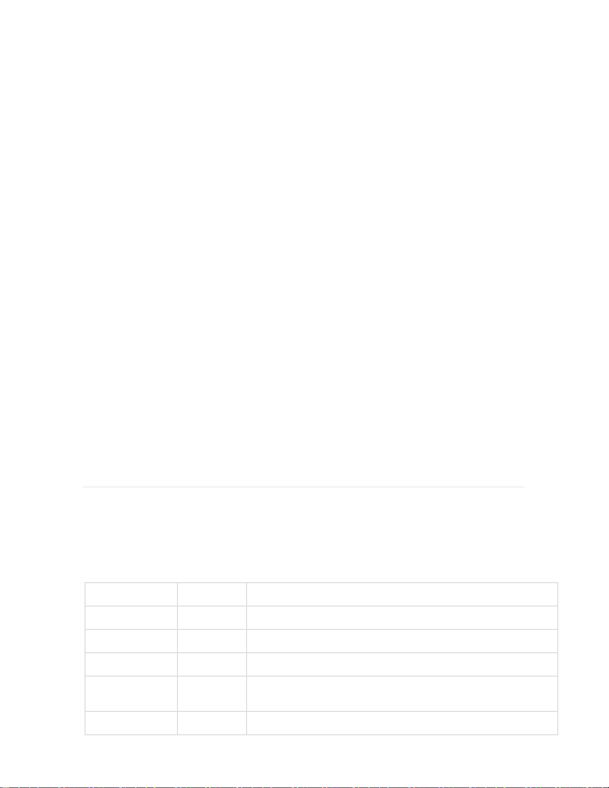
The MG21-HW front panel
Function
LED Status
Meaning
Power Up/Boot
Solid Orange
Power is applied
Connecting
Rainbow
Device in process of connecting to the Meraki Dashboard
Connected
Solid White
Fully operational
Upgrading
Flashing
White
During boot or no WAN link
LTE Enabled
Purple
LTE is on and connected
Ports and Status Indicators
The MG21-HW uses a single LED to inform the user of the device's status.
Page 3
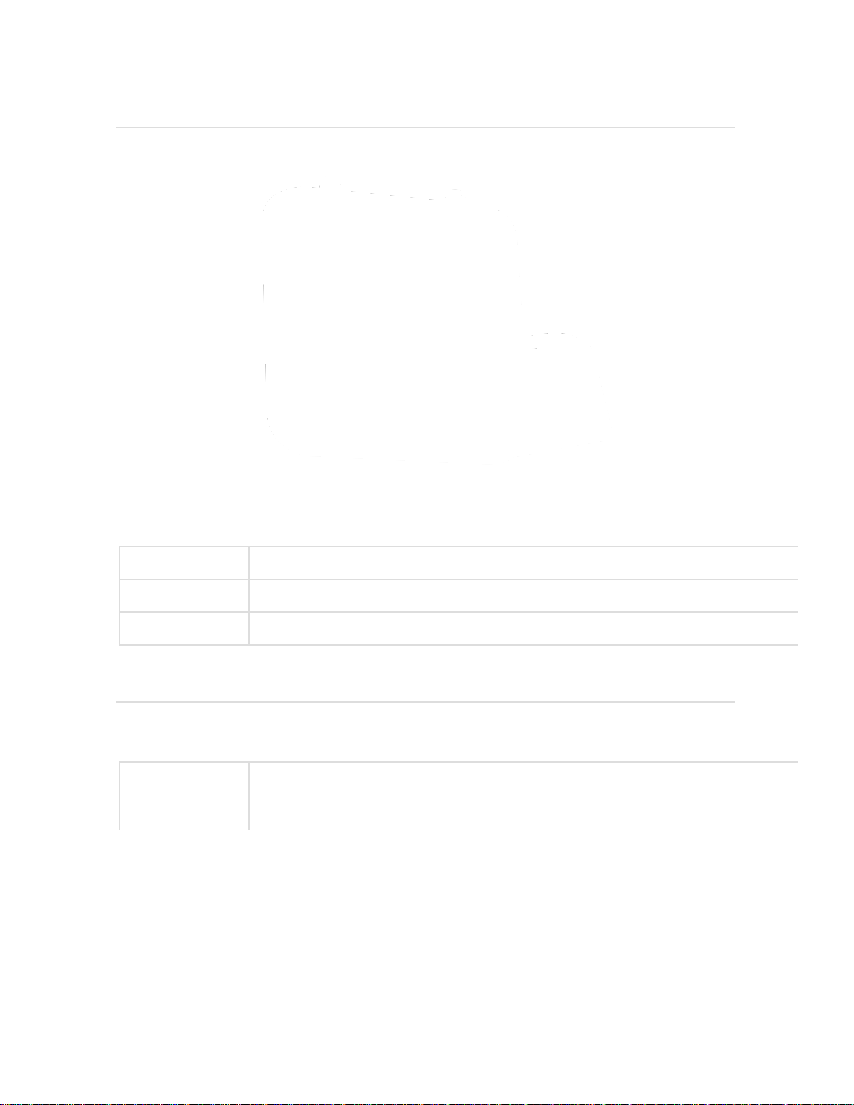
The MG21-HW back panel
Internet ports
Two ports provide connectivity to the WAN.
Power input
Designed for use only with the unit’s power supply.
Antenna ports
Two RP-SMA ports for dipole antennas (two antennas included)
Restore button
Insert a paper clip if a reset is required.
Additional functions on the back panel are described below, from left to right.
The MG21-HW input panel
Page 4

Page 5

Mounting hardware
The supplied wall screws and anchors allow you to mount the appliance on a drywall surface, either
vertically or horizontally. The distance between the holes you drill should be 93 mm.
• For mounting on drywall, use a ¼-in drill bit, then insert the plastic and screw assemblies.
• For mounting on wood or a similar surface, use only the screws.
• Allow the heads of the screws to stick out far enough to be inserted securely into the back of the appliance.
Mount Option A:
Mount Option: B
Mounting The Device:
Page 6

Outdoor Installation
Hardware
The installation for outdoor deployments of the MG21 and MG21E is the same procedure and uses the
same mounting hardware as the indoor deployment.
Power
Powering the MG21 and MG21E in an outdoor deployment will require the use of the POE injector.
IP67 Rating
This device is IP67 rated.
Connecting to the WAN
All Meraki MG devices must have an IP address. This section describes how to configure your local area
network before you deploy it. A local management web service, running on the appliance, is accessed
through a browser running on a client PC. This web service is used for configuring and monitoring basic
ISP/WAN connectivity.
Setting up a static IP address
To ensure that the client PC is redirected to the local web service in the following step, you must disable all
other network services (e.g., Wi-Fi) on your client machine.
Page 7

Do the following to configure basic connectivity and other networking parameters:
1. Using a client machine such as a laptop, connect to one of the LAN ports of the MG.
2. Using a browser on the client machine, access the appliance's built-in web service by browsing
to http://setup.meraki.com. (You do not have to be connected to the Internet to reach this address)
3. Click Uplink configuration under the Local status tab.
4. Choose Static for the IP Assignment option.
5. Enter the IP address, subnet mask, default gateway IP and DNS server information.
Setting up a DHCP IP address
By default all MG devices are configured to DHCP from upstream WAN / ISP servers. Simply plug one of the
MG's WAN / Internet ports into your upstream circuit and wait a few minutes for the unit to negotiate a
DHCP address.
Icon
When the WAN connection is fully enabled, the Internet 1 or 2 LED 1 will turn green.
Additional settings
Please note that all these settings below are accessible only via the local management console.
Setting VLANs
If your WAN uplink is on a trunk port, choose VLAN tagging > Use VLAN tagging and enter the appropriate
value for VLAN ID for your network.
Setting PPPoE
PPPoE authentication may be required if you are connecting the MG to a DSL circuit. You need to know your
authentication option and credentials (supplied by your ISP) in order to complete these steps.
• Choose Connection Type > PPPoE.
• Select your Authentication option.
• If you select Use authentication, enter appropriate values for Username and Password.
Web proxy settings
These settings take effect if the MG device has to fall back to using HTTP to contact the Cloud Controller. By
default, web proxy is disabled. To enable web proxy, do the following:
• Choose Web proxy > Yes.
• Enter values as appropriate for Hostname or IP and Port.
• If you require authentication, choose Authentication > Use authentication, and enter appropriate values
for Username and Password.
To apply all configuration settings to the appliance, be sure to click Save Settings at the bottom of the page.
Configuring physical link settings
Page 8

To configure physical link settings on the Ethernet ports, click Local status > Ethernet configuration. You can
enable half duplex, full duplex, and auto-negotiation, as well as set 10- or 100-Mbps data rates.
Regulatory
FCC Compliance Statement
This device complies with part 15 of the FCC rules. Operation is subject to the following two conditions: (1)
This device may not cause harmful interference, and (2) this device must accept any interference
received, including interference that may cause undesired operation.
Party issuing Supplier’s Declaration of Conformity
Cisco Meraki
500 Terry A. Francois Blvd. San
Francisco, CA
94158
USA
compliance@meraki.com
FCC Interference Statement
This equipment has been tested and found to comply with the limits for a Class B digital device,
pursuant to part 15 of the FCC Rules. These limits are designed to provide reasonable protection
against harmful interference in a residential installation. This equipment generates, uses and can
radiate radio frequency energy and, if not installed and used in accordance with the instructions, may
cause harmful interference to radio communications. However, there is no guarantee that
interference will not occur in a particular installation. If this equipment does cause harmful
interference to radio or television reception, which can be determined by turning the equipment off
and on, the user is encouraged to correct the interference by one of the following measures:
Reorient or relocate the receiving antenna.
Increase the separation between the equipment and receiver.
Connect the equipment into an outlet on a circuit different from which the receiver is connected.
Consult the dealer or an experienced radio/TV technician for help.
FCC Caution
Any changes or modifications no expressly approved by Cisco could void the user’s authority to operate
this equipment. This Transmitter must not be co-located or operation in conjunction with any other
antenna or transmitter.
FCC Radiation Exposure Statement
Page 9

This equipment complies with FCC radiation exposure limits set forth for an uncontrolled environment.
This equipment should be installed and operated with minimum distance 20 cm between the radiator
and your body. This transmitter must not be co-located or operating in conjunction with any other
antenna or transmitter.
FCC Professional Installation Statement
This equipment requires professional installation.
Industry Canada Statement
The MG21-HW-NA, MG21E-HW-NA comply with license-exempt RSSs of the Industry Canada Rules.
Operation is subject to the following two conditions: (1) This device may not cause harmful interference,
and (2) this device must accept any interference received, including interference that may cause
undesired operation.
Ce dispositif est conforme à la norme RSS d’Industrie Canada applicable aux appareils radio exempts de
licence. Son fonctionnement est sujet aux deux conditions suivantes: (1) le dispositif ne doit pas produire
de brouillage préjudiciable, et (2) ce dispositif doit accepter tout brouillage reçu, y compris un brouillage
susceptible de provoquer un fonctionnement indésirable.
This radio transmitter has been approved by Innovation, Science and Economic Development Canada to
operate with the antenna types listed below, with the maximum permissible gain indicated. Antenna
types not included in this list that have a gain greater than the maximum gain indicated for any type
listed are strictly prohibited for use with this device.
Antenna types:
Dipole, Panel
Antenna gain (in dBi):
Innovation, Sciences et Développement économique Canada a approuvé l'utilisation de ce
transmetteur radio avec les types d'antenne énumérés ci-dessous, le gain maximal admissible étant
indiqué. Les types d'antennes non inclus dans cette liste qui ont un gain supérieur au gain maximal
indiqué pour tout type listé sont strictement interdits pour une utilisation avec cet appareil.
Page 10

Antenna types:
Dipole, Panel
Antenna gain (in dBi):
Page 11

Industry Canada Radiation Exposure Statement
This equipment complies with IC radiation exposure limits set forth for an uncontrolled environment.
This equipment should be installed and operated with minimum distance 20 cm between the radiator
& your body.
Déclaration d’exposition aux radiations
Cet équipement est conforme aux limites d’exposition aux rayonnements IC établies pour un
environnement non con trôlé. Cet équipement doit être installé et utilisé avec un minimum de 20 cm
de distance entre la source de rayonnement et votre corps.
 Loading...