

Page 1
Meraki MR74
Hardware Installation Guide
Trademarks
Cisco, Cisco Meraki, Meraki, Meraki MR74, and Meraki Cloud Controller
Page 2

are trademarks of Cisco Systems, Inc.Other brand and product names
are registered trademarks or trademarks of their respective holders.
Warranty
Cisco Systems, Inc. provides a one year warranty on this product. Warranty
details may be found at www.meraki.cisco.com/support.
Table of Contents
. 1 Scope of Document and Related Publications
. 2 MR74 Overview
. 3 Pre-Install Preparation
. 4 Installation Instructions
. 5 Troubleshooting
. 6 Regulatory
1
Scope of Document and Related Publications
The MR74 Hardware Installation Guide describes the installation
procedure for the MR74 access point.
Additional reference documents are available online at
Page 3

meraki.cisco.com/support
2
MR74 Overview
The Meraki MR74 is an enterprise-class, 802.11abgn/ac AP outdoor
designed for rugged environments. When connected to the Meraki Cloud
Controller, the MR74 enables the creation of high-speed and reliable
networks that cover large outdoor and industrial areas quickly, easily, and
cost-effectively.
The Meraki MR74 has an operating temperature of -40o to 60o C.
2.1
Package Contents
The MR74 package contains the following:
- MR74 access point
- Wall screws & anchors
- Mounting plate
- Cable gland
- Mounting straps
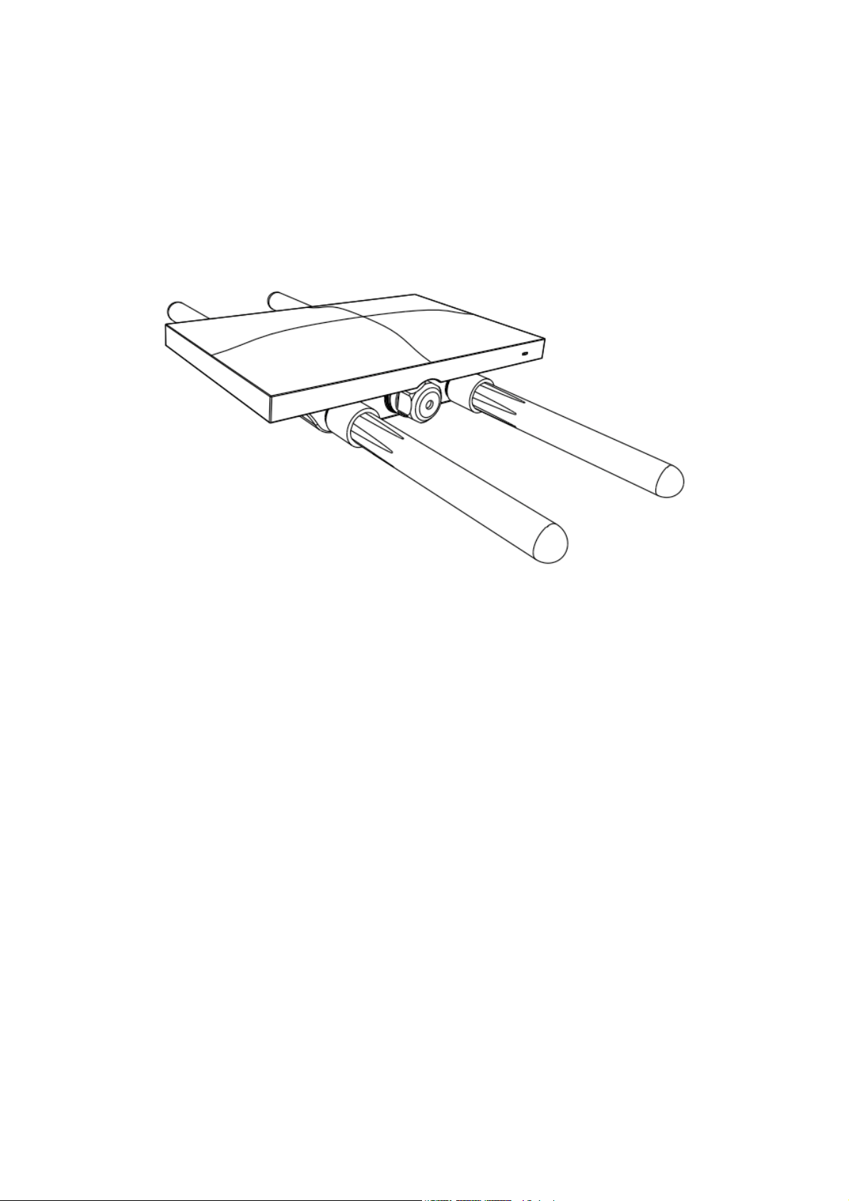
2.2
Antennas and Ports
The Meraki MR74 has two radios. Each radio has two external antenna
connectors; both connectors for a particular radio should be attached to
the same type of antenna. The 5 GHz radio is used for mesh or client
communication. The 2.4 GHz radio is primarily used for client
communication. However, it can also communicate with Meraki 2.4 GHz
access points.
Page 4

Meraki offers a number of different antennas for use with the MR74: MAANT-20, MA-ANT-21, MA-ANT-23, MA-ANT-25, MA-ANT-27, and Cisco
AIR-ANT2513P4M-N.
The Meraki MA-ANT-20 omni-directional antennas must be installed
vertically.
The Meraki MA-ANT-21, MA-ANT-23, MA-ANT-25, MA-ANT-27, and
Cisco AIR-ANT2513P4M-N antennas must be installed facing downward,
at least 30 degrees from the horizon line.
2.3
Power Source Options
The MR74 access point can be powered using either an 802.3af capable
PoE switch or the Meraki 802.3af PoE injector (sold separately).
2.4
LED Indicators and Run Dark Mode
Your MR74 uses a single LED to inform the user of the device’s status.
Function
LED Status
Meaning
Power Up/
Boot
Solid Orange
Power is applied
Connecting
Rainbow
Device in process of connecting to the
Meraki Dashboard
Connected
Solid White
Fully operational
Upgrading
Flashing
White
During boot or no WAN link
The MR74 may be operated in “Run Dark” mode for additional security
and to reduce the visibility of the access point. In this mode, the LED will
not be illuminated. This mode may be enabled through Meraki Dashboard.
Page 5

3
Pre-Install Preparation
You should complete the following steps before going on-site to perform an
installation.
3.1
Configure Your Network in Dashboard
Meraki recommends that you add your MR74 to a network in Dashboard
before mounting it in the field. The following is a brief overview only of the
steps required to add an MR74 to your network. For detailed instructions
about creating, configuring and managing Meraki wireless networks, refer
to the Meraki Cloud Controller Manual
(cisco.meraki.com/support/#documentation).
1. Login to http://dashboard.meraki.com. If this is your first time, create a
new account.
2. Find the network to which you plan to add your nodes or create a new
network.
3. Add your nodes to your network. You will need your Meraki order
number (found on your invoice if you ordered directly from Meraki)
or the serial number of each node, which looks like Qxxx-xxxx-xxxx,
and is found on the bottom of the unit.
4. Finally, go to the map / floor plan view and place each node on the map
by clicking and dragging it to the location where you plan to mount it.
You can always modify the location later.
3.2
Check and Upgrade Firmware
To ensure your MR74 performs optimally immediately following
installation, Meraki recommends that you facilitate a firmware upgrade
prior to mounting your MR74.
1. Attach your MR74 to power and a wired Internet connection.
2. The MR74 will turn on and the LED will glow solid orange. If the unit
does not require a firmware upgrade, the LED will turn solid white
Page 6

within 30 seconds.
* If the unit requires an upgrade, the LED will cycle rainbow until the
upgrade is complete, at which point the Power LED will turn solid white.
You should allow about an hour for the firmware upgrade to complete,
depending on the speed of your internet connection.
3.3
Check and Configure Firewall Settings
If your network will be located behind a firewall, it must allow outgoing
connections on particular ports to particular IP addresses in order for the
MR74 to be able to seamlessly communicate with the Cloud Controller. The
most current list of outbound ports and IP addresses can be found here:
https://documentation.meraki.com/zGeneral_Administration/Other_Top
ics/Firewall_Rules_for_Cloud_Connectivity
3.4
Assigning IP Addresses to MR74s
All gateway MR74s (MR74s with Ethernet connections to the LAN) must
be assigned routable IP addresses. These IP addresses can be dynamically
assigned via DHCP or statically assigned.
3.4.1 Dynamic Assignment
When using DHCP, the DHCP server should be configured to assign a
static IP address for each MAC address belonging to a Meraki AP. Other
features of the wireless network, such as 802.1X authentication, may rely
on the property that the APs have static IP addresses.
3.4.2 Static Assignment
Static IPs are assigned using the local web server on each AP. The following
procedure describes how to set the static IP:
1. Using a client machine (e.g., a laptop), connect to the AP either wirelessly
(by associating to any SSID broadcast by the AP) or over a wired
connection. If using a wired connection, connect the client machine
to the MR74 either through a PoE switch or a Meraki PoE Injector. If
using a PoE switch, plug an Ethernet cable into the MR74’s Ethernet
jack, and the other end into a PoE switch. Then connect the client
machine over Ethernet cable to the PoE switch. If
Page 7

using a Meraki PoE Injector, connect the MR74 to the “PoE” port of
the Injector, and the client machine to the “LAN” port.
2. Using a web browser on the client machine, access the AP’s built-in web
server by browsing to http://ap.meraki.com. Alternatively, browse to
http://10.128.128.128.
3. Click on the “Static IP Configuration” tab. Log in. The default user name
is the AP’s serial number, with hyphens included (e.g., Q2BD-551CZYW3), and the default password is blank.
4. Configure the static IP address, net mask, gateway IP address and DNS
servers that this AP will use on its wired connection.
5. If necessary, reconnect the AP to the LAN.
3.5
Collect Tools
You will need the following tools to perform an installation:
- Flat-head screwdriver
- Drill with appropriate bits for mounting wall anchors (if mounting to a
wall)
- Phillips screwdriver
- Tin snips(if mounting with hose clamps)
- Power screwdriver with 5/16”(8 mm) nut driver, Phillips & flat heads
(recommended)
3.6
Collect Additional Hardware for Installation
- Network cables with RJ45 connectors long enough for your particular
mounting location
- 802.3af PoE power source (either PoE switch or Meraki 802.3af PoE
Injector)
Page 8

- Connection to the internet (if you are setting up your MR74 as a gateway
to the internet)
- Appropriately sized metal straps (if mounting to a pole larger than 3.9” in
diameter)
- Specialized mounting hardware if mounting to surface other than wood,
stucco or stone
- Laptop with wireless to verify setup (recommended)
4
Installation Instructions
4.1
Choose Your Mounting Location
A good mounting location is important to getting the best performance out
of your MR74 access point. Keep the following in mind:
1. The device should have unobstructed line of sight to most coverage areas.
For example, if installing in an office filled with workspaces divided
by mid-height cubicle walls, installing on the ceiling or high on a wall
would be ideal.
2. Power over Ethernet supports a maximum cable length of 300 ft (100 m).
3.If being used in a mesh deployment, the MR74 should have line of sight
to at least two other Meraki devices. For more detailed instructions
regarding access point location selection, reference the Meraki
Network Design Guide (cisco.meraki.com/support/#documentation).
4.The antennas should be as unobstructed as possible. Make sure that
there is clearance around the MR74 for installation of all of your
chosen antennas.
Safety note on mounting locations:
It is recommended that the MR74 be mounted to at a minimum, a 13 mm
thick plywood/concrete wall or ceiling using the mount plate with 6.35
mm in diameter of screws for physical security reasons.
Page 9

4.2
Install the MR74
For most mounting scenarios, the MR74 mount plate provides a quick,
simple, and flexible means of mounting your device. The installation
should be done in two steps. First, install the mount plate to your selected
location. Then attach the MR74 to the mount plate.
4.2.1 Remove the Mount Plate from the Access Point
Before installing the mount plate, you must remove it from the back of the
access point.
1. Unscrew the mount plate attachment screw.
2. Lift the mount plate release tab upwards.
3. While holding the mount plate release tab up, slide the mount plate off
the access point.
4.2.2 Attach the Mount Plate
The MR74 mount plate can be used to install your access point in a wide
range of scenarios.
4.2.2.1 Wall or Solid Ceiling Mount Using Mount Plate
Using included wall anchors and screws, attach the mount plate to your
mounting wall or ceiling.
It is recommended that the MR74 be mounted to a wall or solid ceiling
using the mount plate for physical security reasons.
4.2.2.2 Pole Mount Using Mount Plate
Use the included mounting straps to mount the AP to a pole less than 3.9”
in diameter. Thread the mounting straps through the mounting strap slots
to secure the mount plate in a horizontal or vertical orientation.
4.2.3 Mount the MR74
Insert the posts on the mount plate into the attachment slots on the access
point.
4.2.3.1 Attach Antennas
Page 10

Remove protective plastic covers from all four N-type RF connectors.
Attach appropriate antennas (and protective boots if included).
4.2.3.2 Aim Antennas
If you are using directional antennas, aim them appropriately to ensure
optimal performance for yourspecific network topography.
Omnidirectional antennas perform best in a mesh network when oriented
vertically.
4.2.3.3 Powering the MR74 with the Meraki 802.3at Power over Ethernet
Injector (sold separately)
1. Plug the power cord into the PoE Injector and the other end into
wall power.
2. Plug an Ethernet cable that is connected to an active Ethernet
connection into the “IN” port on the injector.
3. Route Ethernet cable from the “OUT” port on the injector to the
Ethernet port in the bay of the MR74.
For more details, see Meraki 802.3at Power Over Ethernet Injector
datasheet.
4.2.3.4 Powering the MR74 with an 802.3at Power over Ethernet Switch
Route Ethernet cable from a port on an active 802.3at PoE switch to the
Ethernet port in the bay of the MR74.
The MR74 is Gigabit Ethernet-capable. To maximize device performance, a
Gigabit Ethernet-capable switch should be used.
4.2.3.5 Attach Power over Ethernet to the MR74
1. Remove the dust cover from the Ethernet port of the MR74.
Unscrew it with a coin or flathead screwdriver.
2. Route the Ethernet cable from the PoE Injector “OUT” port to the
MR74.
3. Install a cable gland on the MR74 end of the cable.
4. Plug the Ethernet cable into the Ethernet port of the Meraki MR74.
a. Connect the cable to the Ethernet port on the MR74.
Page 11

b. Screw the gland body into the threaded hole of the port. Use
an adjustable wrench to make sure the gland body is fully
seated in the hole.
c. Insert the split ring gasket into the gland body.
d. Screw the cap tightly onto the gland. You may need a
wrench to fully tighten the cap, but take care not to damage
the cable in the process.
Optional: Make the MR74 a gateway
1. Connect an active internet connection to the “IN” port of the PoE injector.
4.2.3.6 Attach Grounding Strap
Connect one end of grounding strap to grounding post with included screw
and washer. Securely attach the other end nearby metal structure.
Note on Outdoor Locations:
The equipment contains no operator access areas and is certified only for
installation, by trained personnel only.
The suitability of the mounting surface to hold the weight of the equipment
shall be evaluated in the installation instructions.
The equipment is intended for use in dry locations.
To protect the equipment in an outdoor location:
a. Ensure the conductive part of the equipment is connected to protective
earth to carry potential fault currents. This equipment is designed to
permit the connection of an 18AWG additional Green/Yellow earthed
conductor to earthing stud of a metal wall mount bracket of the equipment.
b. The equipment enclosure is IP67 rated
4.4 Verify Device Functionality and Test Network
Coverage
1. Check LEDsThe Radio Power LED should be solid white. If it is cycling
rainbow, the firmware is automatically upgrading and the LED
should turn white when the upgrade is completed (normally in under
thirty minutes).
Page 12

2. Note: Your MR74 must have an active route to the Internet to check and
upgrade its firmware.
3. Verify access point connectivityUse any 802.11 client device to connect
to the MR74 and verify proper connectivity using the client’s web
browser.
4. Check network coverageConfirm that you have good signal strength
throughout your coverage area. You can use the signal strength
meter on a laptop, smart phone, or other wireless device.
5
Troubleshooting
Reference the Meraki knowledge base at http://meraki.com/support/#kb
for additional information and troubleshooting tips.
6
Regulatory
Professional installation instruction
1. Installation personnel
This product is designed for specific application and needs to be installed
by a qualified personal who has RF and related rule knowledge. The
general user shall not attempt to install or change the setting.
2. Professional Installation Requirements
The following requirements for installation and operation of outdoor systems must be
addressed:
Operation in the 5600-5650-MHz band is not authorized for 5-GHz WLAN systems,
whether operating indoors or outdoors. This does not pose a problem for Cisco® WLAN
since this band is not accessible for Cisco products.
Use of indoor-only equipment outdoors can lead to FCC enforcement action, such as
fines or requirements to disable the system. This includes installations where the
access point is placed indoors and the antenna is placed outdoors, as well as
installations involving retractable roofs (for example, football stadiums).
For WLAN systems being installed outdoors, the following requirements must be
met.
a) Systems must be professionally installed by a qualified engineer familiar
with WLAN, including Cisco trained partners and resellers.
b) Operation in the 5600-5650-MHz band is prohibited.
c) It is recommended that the installer register the installation of their system in
the Wireless Internet Service Providers Association (WISPA database). This is
especially important for systems that are installed within 35 km of the FAA TDWR.
Page 13

(Please see the links later in this document to WISPA database with TDWR
locations.)
d) When within 35 km distance of a TDWR, the center frequency of the WLAN
must be separated from the TDWR center frequency by 30 MHz.
a. If the radar is operating from 5600-5610 MHz, disable the use of channel
116 (5580 MHz).
b. If the radar is operating from 5630-5650 MHz, disable the use of channel
132 (5660 MHz).
Note: Cisco will be disabling channels 116 and 132 for outdoor systems in the
future, the instructions in (d) only applies to systems that currently have the
channels enabled.
e) Additional mitigation techniques can include first, not orienting the antennas
in the main beam of the weather radar, and second, ensuring that the antenna is not
positioned in line-of-sight of the FAA TDWR.
f) Verify that the antennas used are approved for use with Cisco WLAN systems.
Installers or operators using non-approved antennas or making any unauthorized
changes may be subject to enforcement action.
g) Operation in the 5150-5250MHz is restricted to indoor use only.
Installers and operators shall consult the Wireless Internet Service Providers
Association (WISPA) database to determine if they are within 35 km of the Terminal
Doppler Weather Radar (TDWR), as well as to register the system if operating within
this range of the TDWR.
For outdoor operation of the AP in the 5150-5250 MHz band, the
maximum output power shall not exceed 1W. EIRP at any elevation angle
above 30 degrees (as measured from the horizon) shall not exceed 125mW,
per the FCC Part 15.407 rules. The highest antenna gains from the horizon
above 30 degrees are as below:
Page 14

And the following condition for maximum EIRP must apply:
and shall not exceed 21 dBm above 30 degrees over the
horizon. This is maintained through the Cisco Meraki Software Defined
Radio implementation, limiting the power output at a given band, limiting
the maximum EIRP for 5150-5250 MHz to 21 dBm when implemented
outdoors. All power limits and band usage according to FCC rules are
implemented through the SDR.
3. Installation location
The product shall be installed at a location where the radiating antenna can
be kept 36cm from nearby person in normal operation condition to meet
regulatory RF exposure requirement.
4. External antenna
Use only the antennas which have been approved by the applicant. The
non-approved antenna(s) may produce unwanted spurious or excessive RF
transmitting power which may lead to the violation of FCC limit and is
Page 15

prohibited.
5. Installation procedure
Page 16

Please refer to user’s manual for the detail.
6. Warning
Please carefully select the installation position and make sure that the final
output power does not exceed the limit set force in relevant rules. The
violation of the rule could lead to serious federal penalty.
Instructions d'installation professionnelle
1. Installation
Ce produit est destine a un usage specifique et doit etre installe par un
personnel qualifie maitrisant les radiofrequences et les regles s'y
rapportant. L'installation et les reglages ne doivent pas etre modifies par
l'utilisateur final.
2. Emplacement d'installation
En usage normal, afin de respecter les exigences reglementaires
concernant l'exposition aux radiofrequences, ce produit doit etre installe de
facon a respecter une distance de 36 cm entre l'antenne emettrice et les
personnes.
3. Antenn externe.
Utiliser uniiquement les antennes approuvees par le fabricant. L'utilisation
d'autres antennes peut conduire a un niveau de rayonnement essentiel ou
non essentiel depassant les niveaux limites definis par FCC, ce qui est
interdit.
4. Procedure d'installation
Consulter le manuel d'utilisation.
5. Avertissement
Choisir avec soin la position d'installation et s'assurer que la puissance de
sortie ne depasse pas les limites en vigueur. La violation de cette regle peut
conduire a de serieuses penalites federales.
Page 17

FCC Compliance Statement This device complies with part 15 of the FCC rules. Operation is subject to
the following two conditions: (1) This device may not cause harmful
interference, and (2) this device must accept any interference received,
including interference that may cause undesired operation.
FCC Interference Statement
This equipment has been tested and found to comply with the limits for a
Class B digital device, pursuant to part 15 of the FCC Rules. These limits
are designed to provide reasonable protection against harmful interference
in a residential installation. This equipment generates, uses and can
radiate radio frequency energy and, if not installed and used in accordance
with the instructions, may cause harmful interference to radio
communications. However, there is no guarantee that interference will not
occur in a particular installation. If this equipment does cause harmful
interference to radio or television reception, which can be determined by
turning the equipment off and on, the user is encouraged to correct the
interference by one of the following measures:
• Reorient or relocate the receiving antenna.
• Increase the separation between the equipment and receiver.
• Connect the equipment into an outlet on a circuit different from which
the receiver is connected.
• Consult the dealer or an experienced radio/TV technician for help.
FCC Caution
Any changes or modifications no expressly approved by Meraki could void
the user’s authority to operate this equipment. This Transmitter must not
be co-located or operation in conjunction with any other antenna or
transmitter.
FCC Radiation Exposure Statement
This equipment complies with FCC radiation exposure limits set forth for
an uncontrolled environment. This equipment should be installed and
operated with minimum distance 36 cm between the radiator and your
body. This transmitter must not be co-located or operating in conjunction
with any other antenna or transmitter.
IEEE 802.11b or 802.11g operation of this product in the USA is firmware-
Page 18

limited to channels 1 through 11.
If the device is going to be operated in the 5.15 - 5.25 frequency range, then
it is restricted to indoor environment only. This device meets all other
requirements specified in Part 15E, Section 15.407 of the FCC Rules.
Professional installation instruction
1. Installation personal
This product is designed for specific applications and needs to be installed
by qualified personnel who have appropriate RF and related regulation
knowledge. The general user shall not attempt to install or change the
setting.
2. Installation location
The product shall be installed at a location where the radiating antenna can
be kept at least 43cm away from nearby persons while in normal operating
conditions to meet regulatory RF exposure requirements
3. External antennas
Use only the antennas that have been approved by the applicant.
Unapproved antenna(s) may produce unwanted spurious or excessive RF
transmitting power that may lead to violation of IC limits and is prohibited.
4. Installation procedure
Please follow details listed in the appropriate install guides and user
manuals.
5. Warning
Select an installation position that ensures that the final output power does
not exceed the limit set forth in the relevant rules. Violation of this rule
could lead to serious federal penalty
Page 19

Instructions d'installation professionnelle
1. Installation
Ce produit est destine a un usage specifique et doit etre installe par un
personnel qualifie maitrisant les radiofrequences et les regles s'y
rapportant. L'installation et les reglages ne doivent pas etre modifies par
l'utilisateur final.
2. Emplacement d'installation
En usage normal, afin de respecter les exigences reglementaires
concernant l'exposition aux radiofrequences, ce produit doit etre installe de
facon a respecter une distance de 43 cm entre l'antenne emettrice et les
personnes.
3. Antenn externe.
Utiliser uniiquement les antennes approuvees par le fabricant. L'utilisation
d'autres antennes peut conduire a un niveau de rayonnement essentiel ou
non essentiel depassant les niveaux limites definis par IC, ce qui est
interdit.
4. Procedure d'installation
Consulter le manuel d'utilisation.
5. Avertissement
Choisir avec soin la position d'installation et s'assurer que la puissance de
sortie ne depasse pas les limites en vigueur. La violation de cette regle peut
conduire a de serieuses penalites federales.
Industry Canada Statement This device complies with RSS-247 of the Industry Canada Rules.
Operation is subject to the following two conditions: (1) This device may
not cause harmful interference, and (2) this device must accept any
interference received, including interference that may cause undesired
operation. (3) this device subject to this section shall not be capable of
transmitting in the band 5600-5650 MHz. This restriction is for the
protection of Environment Canada’s weather radars operating in this band.
Page 20

Ce dispositif est conforme à la norme CNR-247 d’Industrie Canada
applicable aux appareils radio exempts de licence. Son fonctionnement est
sujet aux deux conditions suivantes: (1) le dispositif ne doit pas produire de
brouillage préjudiciable, et (2) ce dispositif doit accepter tout brouillage
reçu, y compris un brouillage susceptible de provoquer un fonctionnement
indésirable. (3) Ce dispositif soumis au présent article ne doit pas pouvoir
émettre dans la bande 5600-5650 MHz. Cette restriction vise la protection
des radars météorologiques d'Environnement Canada qui fonctionnent
dans cette bande.
Industry Canada Caution
(i) the device for operation in the band 5150-5250 MHz is only for indoor
use to reduce the potential for harmful interference to co-channel mobile
satellite systems;
(ii) high-power radars are allocated as primary users (i.e. priority users) of
the bands 5250-5350 MHz and 5650-5850 MHz and that these radars
could cause interference and/or damage to LE-LAN devices.
Avertissement:
(i) les dispositifs fonctionnant dans la bande 5 150-5 250 MHz sont
réservés uniquement pour une utilisation à l’intérieur afin de réduire les
risques de brouillage préjudiciable aux systèmes de satellites mobiles
utilisant les mêmes canaux;
(ii) De plus, les utilisateurs devraient aussi être avisés que les utilisateurs
de radars de haute puissance sont désignés utilisateurs principaux (c.-à-d.,
qu’ils ont la priorité) pour les bandes 5 250-5 350 MHz et 5 650-5 850
MHz et que ces
radars pourraient causer du brouillage et/ou des dommages aux dispositifs
LAN-EL.
Industry Canada Radiation Exposure Statement This equipment complies with IC radiation exposure limits set forth for an
uncontrolled environment. This equipment should be installed and
operated with minimum distance 43cm between the radiator & your body.
Déclaration d’exposition aux radiations
Cet équipement est conforme aux limites d’exposition aux rayonnements
IC établies pour un environnement non con trôlé. Cet équipement doit être
Page 21

installé et utilisé avec un minimum de 43 cm de distance entre la source de
rayonnement et votre corps.
低功率電波輻射性電機管理辦法
第十二條 經型式認證合格之低功率射頻電機,非經許可,公司、商號
或使用者均不得擅自變更頻率、加大功率或變更原設計之特
第十四條 低功率射頻電機之使用不得影響飛航安全及干擾合法通信;
經發現有干擾現象時,應立即停用,並改善至無干擾時方得
繼續使用。
前項合法通信,指依電信法規定作業之無線電通
信。
低功率射頻電機須忍受合法通信或工業、科學及醫療用
電磁波曝露量MPE標準值1mW/cm
2
,本產品使用時建議應距離
人體 36 cm。
[警語內容]
1.
使用此產品時應避免影響附近雷達系統之操作。
 Loading...