

Page 1
Meraki MR72
Hardware Installation Guide
Page 2

Trademarks
Cisco, Cisco Meraki, Meraki, Meraki MR72, and Meraki Cloud
Controller are trademarks of Cisco Systems, Inc. Other brand and
product names are registered trademarks or trademarks of their
respective holders.
Warranty
Cisco Systems, Inc. provides a one year warranty on this product.
Warranty details may be found at www.meraki.cisco.com/support.
Table of Contents
. 1 Scope of Document and Related Publications
. 2 MR72 Overview
. 3 Pre-Install Preparation
. 4 Installation Instructions
. 5 Troubleshooting
. 6 Regulatory
Page 3

1 Scope of Document and Related Publications
The MR72 Hardware Installation Guide describes the installation
procedure for the MR72 access point.
Additional reference documents are available online at
meraki.cisco.com/support
2 MR72 Overview
The Meraki MR72 is an enterprise-class, 802.11abgn/ac outdoor
access point designed for rugged environments. When connected to
the Meraki Cloud Controller, the MR72 enables the creation of highspeed and reliable networks that cover large outdoor and industrial
areas quickly, easily, and cost-effectively.
The Meraki MR72 has an operating temperature of -40o to 60o C.
2.1 Package Contents
The MR72 package contains the following:
- MR72 access point
- Wall screws & anchors
- Mounting plate
- Cable gland
- Mounting straps
Page 4

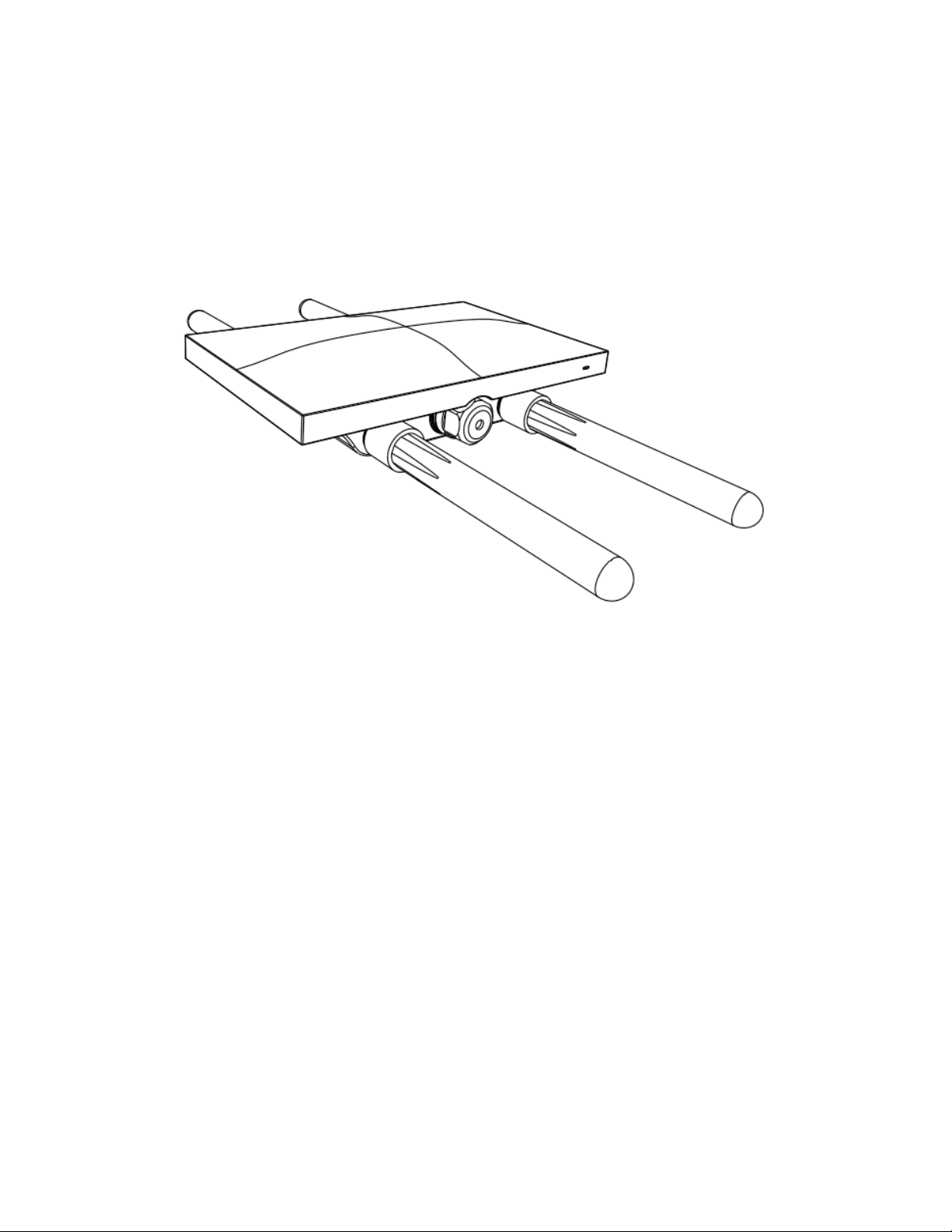
2.2 Antennas and Ports
The Meraki MR72 has two radios. Each radio has two external antenna
connectors; both connectors for a particular radio should be attached
to the same type of antenna. The 5 GHz radio is used for mesh or client
communication. The 2.4 GHz radio is primarily used for client
communication. However, it can also communicate with Meraki 2.4
GHz access points.
Meraki offers a number of different antennas for use with the MR72:
MA-ANT-20, MA-ANT-21, MA-ANT-23, and MA-ANT-25.
The Meraki MA-ANT-20 omni-directional antennas must be installed
vertically.
The Meraki MA-ANT-25 patch antenna must be installed facing
downward, at least 30 degrees from the horizon line.
2.3 Power Source Options
The MR72 access point can be powered using either an 802.3at
capable PoE switch or the Meraki 802.3at PoE injector (sold
separately).
2.4 LED Indicators and Run Dark Mode
Your MR72 uses a single LED to inform the user of the device’s status.
Function
LED Status
Meaning
Page 5

Power Up/
Boot
Solid
Orange
Power is applied
Connecting
Rainbow
Device in process of connecting to
the Meraki Dashboard
Connected
Solid White
Fully operational
Upgrading
Flashing
White
During boot or no WAN link
The MR72 may be operated in “Run Dark” mode for additional security
and to reduce the visibility of the access point. In this mode, the LED
will not be illuminated. This mode may be enabled through Meraki
Dashboard.
3 Pre-Install Preparation
You should complete the following steps before going on-site to
perform an installation.
3.1 Configure Your Network in Dashboard
Meraki recommends that you add your MR72 to a network in
Dashboard before mounting it in the field. The following is a brief
overview only of the steps required to add an MR72 to your network.
For detailed instructions about creating, configuring and managing
Meraki wireless networks, refer to the Meraki Cloud Controller Manual
(cisco.meraki.com/support/#documentation).
1. Login to http://dashboard.meraki.com. If this is your first time,
create a new account.
Page 6

2. Find the network to which you plan to add your nodes or create a
new network.
3. Add your nodes to your network. You will need your Meraki order
number (found on your invoice if you ordered directly from
Meraki) or the serial number of each node, which looks like
Qxxx-xxxx-xxxx, and is found on the bottom of the unit.
4. Finally, go to the map / floor plan view and place each node on
the map by clicking and dragging it to the location where you
plan to mount it. You can always modify the location later.
3.2 Check and Upgrade Firmware
To ensure your MR72 performs optimally immediately following
installation, Meraki recommends that you facilitate a firmware upgrade
prior to mounting your MR72.
1. Attach your MR72 to power and a wired Internet connection.
2. The MR72 will turn on and the LED will glow solid orange. If the
unit does not require a firmware upgrade, the LED will turn solid
white within 30 seconds.
* If the unit requires an upgrade, the LED will cycle rainbow until the
upgrade is complete, at which point the Power LED will turn solid
white. You should allow about an hour for the firmware upgrade to
complete, depending on the speed of your internet connection.
3.3 Check and Configure Firewall Settings
If your network will be located behind a firewall, it must allow outgoing
connections on particular ports to particular IP addresses in order for
Page 7

the MR72 to be able to seamlessly communicate with the Cloud
Controller. The most current list of outbound ports and IP addresses
can be found here:
http://bit.ly/oZpMQ7
3.4 Assigning IP Addresses to MR72s
All gateway MR72s (MR72s with Ethernet connections to the LAN)
must be assigned routable IP addresses. These IP addresses can be
dynamically assigned via DHCP or statically assigned.
3.4.1 Dynamic Assignment
When using DHCP, the DHCP server should be configured to assign a
static IP address for each MAC address belonging to a Meraki AP.
Other features of the wireless network, such as 802.1X authentication,
may rely on theproperty that the APs have static IP addresses.
3.4.2 Static Assignment
Static IPs are assigned using the local web server on each AP. The
following procedure describes how to set the static IP:
1. Using a client machine (e.g., a laptop), connect to the AP either
wirelessly (by associating to any SSID broadcast by the AP) or
over a wired connection. If using a wired connection, connect
the client machine to the MR72 either through a PoE switch or a
Meraki PoE Injector. If using a PoE switch, plug an Ethernet cable
into the MR72’s Ethernet jack, and the other end into a PoE
switch. Then connect the client machine over Ethernet cable to
the PoE switch. If using a Meraki PoE Injector, connect the MR72
to the “PoE” port of the Injector, and the client machine to the
“LAN” port.
2. Using a web browser on the client machine, access the AP’s
Page 8

built-in web server by browsing to http://ap.meraki.com.
Alternatively, browse to http://10.128.128.128.
3. Click on the “Static IP Configuration” tab. Log in. The default
user name is “admin”. The default password is the AP’s serial
number, with hyphens included (e.g., Q2BD-551C-ZYW3).
4. Configure the static IP address, net mask, gateway IP address
and DNS servers that this AP will use on its wired connection.
5. If necessary, reconnect the AP to the LAN.
3.5 Collect Tools
You will need the following tools to perform an installation:
- Flat-head screwdriver
- Drill with appropriate bits for mounting wall anchors (if mounting to a
wall)
- Phillips screwdriver
- Tin snips (if mounting with hose clamps)
- Power screwdriver with 5/16” (8 mm) nut driver, Phillips & flat heads
(recommended)
3.6 Collect Additional Hardware for Installation
- Network cables with RJ45 connectors long enough for your particular
mounting location
- 802.3at PoE power source (either PoE switch or Meraki 802.3at PoE
Injector)
Page 9

- Connection to the internet (if you are setting up your MR72 as a
gateway to the internet)
- Appropriately sized metal straps (if mounting to a pole larger than
3.9” in diameter)
- Specialized mounting hardware if mounting to surface other than
wood, stucco or stone
- Laptop with wireless to verify setup (recommended)
4 Installation Instructions
4.1 Choose Your Mounting Location
A good mounting location is important to getting the best performance
out of your MR72 access point. Keep the following in mind:
1. The device should have unobstructed line of sight to most
coverage areas. For example, if installing in an office filled with
workspaces divided by mid-height cubicle walls, installing on the
ceiling or high on a wall would be ideal.
2. Power over Ethernet supports a maximum cable length of 300 ft
(100 m).
3. If being used in a mesh deployment, the MR72 should have line
of sight to at least two other Meraki devices. For more detailed
instructions regarding access point location selection, reference
the Meraki Network Design Guide
(cisco.meraki.com/support/#documentation).
4. The antennas should be as unobstructed as possible. Make sure
that there is clearance around the MR72 for installation of all of
your chosen antennas.
Page 10

4.2 Install the MR72
For most mounting scenarios, the MR72 mount plate provides a quick,
simple, and flexible means of mounting your device. The installation
should be done in two steps. First, install the mount plate to your
selected location. Then attach the MR72 to the mount plate.
4.2.1 Remove the Mount Plate from the Access Point
Before installing the mount plate, you must remove it from the back of
the access point.
1. Unscrew the mount plate attachment screw.
2. Lift the mount plate release tab upwards.
3. While holding the mount plate release tab up, slide the mount plate
off the access point.
4.2.2 Attach the Mount Plate
The MR72 mount plate can be used to install your access point in a
wide range of scenarios.
4.2.2.1 Wall or Solid Ceiling Mount Using Mount Plate
Using included wall anchors and screws, attach the mount plate to
your mounting wall or ceiling.
It is recommended that the MR72 be mounted to a wall or solid ceiling
using the mount plate for physical security reasons.
4.2.2.2 Pole Mount Using Mount Plate
Use the included mounting straps to mount the AP to a pole less than
3.9” in diameter. Thread the mounting straps through the mounting
strap slots to secure the mount plate in a horizontal or vertical
Page 11

orientation.
4.2.3 Mount the MR72
Insert the posts on the mount plate into the attachment slots on the
access point.
4.2.3.1 Attach Antennas
Remove protective plastic covers from all four N-type RF connectors.
Attach appropriate antennas (and protective boots if included).
4.2.3.2 Aim Antennas
If you are using directional antennas, aim them appropriately to ensure
optimal performance for your specific network topography.
Omnidirectional antennas perform best in a mesh network when
oriented vertically.
4.2.3.3 Powering the MR72 with the Meraki 802.3at Power over
Ethernet Injector (sold separately)
1. Plug the power cord into the PoE Injector and the other end
into wall power.
2. Plug an Ethernet cable that is connected to an active Ethernet
connection into the “IN” port on the injector.
3. Route Ethernet cable from the “OUT” port on the injector to
the Ethernet port in the bay of the MR72.
For more details, see Meraki 802.3at Power Over Ethernet Injector
datasheet.
4.2.3.4 Powering the MR72 with an 802.3at Power over Ethernet
Switch
Route Ethernet cable from a port on an active 802.3at PoE switch to
the Ethernet port in the bay of the MR72.
Page 12

The MR72 is Gigabit Ethernet-capable. To maximize device
performance, a Gigabit Ethernet-capable switch should be used.
4.2.3.5 Attach Power over Ethernet to the MR72
1. Remove the dust cover from the Ethernet port of the MR72.
Unscrew it with a coin or flathead screwdriver.
2. Route the Ethernet cable from the PoE Injector “OUT” port to
the MR72.
3. Install a cable gland on the MR72 end of the cable.
4. Plug the Ethernet cable into the Ethernet port of the Meraki
MR72.
a. Connect the cable to the Ethernet port on the MR72.
b. Screw the gland body into the threaded hole of the port.
Use an adjustable wrench to make sure the gland body is
fully seated in the hole.
c. Insert the split ring gasket into the gland body.
d. Screw the cap tightly onto the gland. You may need a
wrench to fully tighten the cap, but take care not to
damage the cable in the process.
Optional: Make the MR72 a gateway
1. Connect an active internet connection to the “IN” port of the PoE
injector.
4.2.3.6 Attach Grounding Strap
Connect one end of grounding strap to grounding post with included
screw and washer. Securely attach the other end nearby metal
structure.
Page 13

4.4 Verify Device Functionality and Test Network
Coverage
1. Check LEDs The Radio Power LED should be solid white. If it is
cycling rainbow, the firmware is automatically upgrading and the
LED should turn white when the upgrade is completed (normally
in under thirty minutes).
2. Note: Your MR72 must have an active route to the Internet to
check and upgrade its firmware.
3. Verify access point connectivity Use any 802.11 client device to
connect to the MR72 and verify proper connectivity using the
client’s web browser.
4. Check network coverage Confirm that you have good signal
strength throughout your coverage area. You can use the signal
strength meter on a laptop, smart phone, or other wireless
device.
5 Troubleshooting
Reference the Meraki knowledge base at
http://meraki.com/support/#kb for additional information and
troubleshooting tips.
!
!
6 Regulatory
FCC Compliance Statement
This device complies with part 15 of the FCC rules. Operation is
subject to the following two conditions: (1) This device may not cause
harmful interference, and (2) this device must accept any interference
Page 14

received, including interference that may cause undesired operation.
FCC Interference Statement
This equipment has been tested and found to comply with the limits for
a Class B digital device, pursuant to part 15 of the FCC Rules. These
limits are designed to provide reasonable protection against harmful
interference in a residential installation. This equipment generates,
uses and can radiate radio frequency energy and, if not installed and
used in accordance with the instructions, may cause harmful
interference to radio communications. However, there is no guarantee
that interference will not occur in a particular installation. If this
equipment does cause harmful interference to radio or television
reception, which can be determined by turning the equipment off and
on, the user is encouraged to correct the interference by one of the
following measures:
• Reorient or relocate the receiving antenna.
• Increase the separation between the equipment and receiver.
• Connect the equipment into an outlet on a circuit different from which
the receiver is connected.
• Consult the dealer or an experienced radio/TV technician for help.
FCC Caution
Any changes or modifications no expressly approved by Meraki could
void the user’s authority to operate this equipment. This Transmitter
must not be co-located or operation in conjunction with any other
antenna or transmitter.
FCC Radiation Exposure Statement
This equipment complies with FCC radiation exposure limits set forth
for an uncontrolled environment. This equipment should be installed
and operated with minimum distance 34 cm between the radiator and
your body. This transmitter must not be co-located or operating in
Page 15

conjunction with any other antenna or transmitter.
IEEE 802.11b or 802.11g operation of this product in the USA is
firmware-limited to channels 1 through 11.
If the device is going to be operated in the 5.15 - 5.25 frequency
range, then it is restricted to indoor environment only. This device
meets all other requirements specified in Part 15E, Section 15.407 of
the FCC Rules.
Industry Canada Statement
This device complies with RSS-210 of the Industry Canada Rules.
Operation is subject to the following two conditions: (1) This device
may not cause harmful interference, and (2) this device must accept
any interference received, including interference that may cause
undesired operation.
Ce dispositif est conforme à la norme CNR-210 d’Industrie Canada
applicable aux appareils radio exempts de licence. Son
fonctionnement est sujet aux deux conditions suivantes: (1) le dispositif
ne doit pas produire de brouillage préjudiciable, et (2) ce dispositif doit
accepter tout brouillage reçu, y compris un brouillage susceptible de
provoquer un fonctionnement indésirable.
Industry Canada Caution
(i) the device for operation in the band 5150-5250 MHz is only for
indoor use to reduce the potential for harmful interference to cochannel mobile satellite systems;
(ii) high-power radars are allocated as primary users (i.e. priority users)
of the bands 5250-5350 MHz and 5650-5850 MHz and that these
radars could cause interference and/or damage to LE-LAN devices.
Avertissement:
(i) les dispositifs fonctionnant dans la bande 5 150-5 250 MHz sont
réservés uniquement pour une utilisation à l’intérieur afin de réduire les
Page 16

risques de brouillage préjudiciable aux systèmes de satellites mobiles
utilisant les mêmes canaux;
(ii) De plus, les utilisateurs devraient aussi être avisés que les
utilisateurs de radars de haute puissance sont désignés utilisateurs
principaux (c.-à-d., qu’ils ont la priorité) pour les bandes 5 250-5 350
MHz et 5 650-5 850 MHz et que ces
radars pourraient causer du brouillage et/ou des dommages aux
dispositifs LAN-EL.
Industry Canada Radiation Exposure Statement
This equipment complies with IC radiation exposure limits set forth for
an uncontrolled environment. This equipment should be installed and
operated with minimum distance 34 cm between the radiator & your
body.
Déclaration d’exposition aux radiations
Cet équipement est conforme aux limites d’exposition aux
rayonnements IC établies pour un environnement non con trôlé. Cet
équipement doit être installé et utilisé avec un minimum de 34 cm de
distance entre la source de rayonnement et votre corps.
!
!
 Loading...