

Page 1

Cisco ASA 5505 Adaptive Security
Appliance Hardware Installation Guide
Americas Headquarters
Cisco Systems, Inc.
170 West Tasman Drive
San Jose, CA 95134-1706
USA
http://www.cisco.com
Tel: 408 526-4000
800 553-NETS (6387)
Fax: 408 527-0883
Customer Order Number: OL-18362-01
Text Part Number: OL-18362-01
Page 2

THE SPECIFICATIONS AND INFORMATION REGARDING THE PRODUCTS IN THIS MANUAL ARE SUBJECT TO CHANGE WITHOUT NOTICE. ALL
STATEMENTS, INFORMATION, AND RECOMMENDATIONS IN THIS MANUAL ARE BELIEVED TO BE ACCURATE BUT ARE PRESENTED WITHOUT
WARRANTY OF ANY KIND, EXPRESS OR IMPLIED. USERS MUST TAKE FULL RESPONSIBILITY FOR THEIR APPLICATION OF ANY PRODUCTS.
THE SOFTWARE LICENSE AND LIMITED WARRANTY FOR THE ACCOMPANYING PRODUCT ARE SET FORTH IN THE INFORMATION PACKET THAT
SHIPPED WITH THE PRODUCT AND ARE INCORPORATED HEREIN BY THIS REFERENCE. IF YOU ARE UNABLE TO LOCATE THE SOFTWARE LICENSE
OR LIMITED WARRANTY, CONTACT YOUR CISCO REPRESENTATIVE FOR A COPY.
The following inform ation is for FCC compliance of Class A devices: This equipment has been tested and found to comply with the limits for a Class A digital device, pursuant
to part 15 of the FCC rules. These limits are designed to provide reasonable protection against harmful interference when the equipment is operated in a commercial
environment. This equipment generates, uses, and can radiate radio-frequency energy and, if not installed and used in accordance with the instruction manual, may cause
harmful interference to radio communications. Operation of this equipment in a residential area is likely to cause harmful interference, in which case users will be required
to correct the interference at their own expense.
The following information is for FCC compliance of Class B devices: The equipment described in this manual generates and may radiate radio-frequency energy. If it is not
installed in accordance with Cisco’s installation instructions, it may cause interference with radio and television reception. This equipment has been tested and found to
comply with the limits for a Class B digital device in accordance with the specifications in part 15 of the FCC rules. These specifications are designed to provide reasonable
protection against such interference in a residential installation. However, there is no guarantee that interference will not occur in a particular installation.
Modifying the equipment without Cisco’s written authorization may result in the equipment no longer complying with FCC requirements for Class A or Class B digital
devices. In that event, your right to use the equipment may be limited by FCC regulations, and you may be required to correct any interference to radio or television
communications at your own expense.
You can determine whether your equipment is causing interference by turning it off. If the interference stops, it was probably caused by the Cisco equipment or one of its
peripheral devices. If the equipment causes interference to radio or television reception, try to correct the interference by using one or more of the following measures:
• Turn the television or radio antenna until the interference stops.
• Move the equipment to one side or the other of the television or radio.
• Move the equipment farther away from the television or radio.
• Plug the equipment into an outlet that is on a different circuit from the television or radio. (That is, make certain the equipment and the television or radio are on circuits
controlled by different circuit breakers or fuses.)
Modifications to this product not authorized by Cisco Systems, Inc. could void the FCC approval and negate your authority to operate the product.
The Cisco implementation of TCP header compression is an adaptation of a program developed by the University of California, Berkeley (UCB) as part of UCB’s public
domain version of the UNIX operating system. All rights reserved. Copyright © 1981, Regents of the University of California.
NOTWITHSTANDING ANY OTHER WARRANTY HEREIN, ALL DOCUMENT FILES AND SOFTWARE OF THESE SUPPLIERS ARE PROVIDED “AS IS” WITH
ALL FAULTS. CISCO AND THE ABOVE-NAMED SUPPLIERS DISCLAIM ALL WARRANTIES, EXPRESSED OR IMPLIED, INCLUDING, WITHOUT
LIMITATION, THOSE OF MERCHANTABILITY, FITNESS FOR A PARTICULAR PURPOSE AND NONINFRINGEMENT OR ARISING FROM A COURSE OF
DEALING, USAGE, OR TRADE PRACTICE.
IN NO EVENT SHALL CISCO OR ITS SUPPLIERS BE LIABLE FOR ANY INDIRECT, SPECIAL, CONSEQUENTIAL, OR INCIDENTAL DAMAGES, INCLUDING,
WITHOUT LIMITATION, LOST PROFITS OR LOSS OR DAMAGE TO DATA ARISING OUT OF THE USE OR INABILITY TO USE THIS MANUAL, EVEN IF CISCO
OR ITS SUPPLIERS HAVE BEEN ADVISED OF THE POSSIBILITY OF SUCH DAMAGES.
Cisco and the Cisco Logo are trademarks of Cisco Systems, Inc. and/or its affiliates in the U.S. and other countries. A listing of Cisco's trademarks can be found at
www.cisco.com/go/trademarks. Third party trademarks mentioned are the property of their respective owners. The use of the word partner does not imply a partnership
relationship between Cisco and any other company. (1005R)
Cisco ASA 5505 Adaptive Security Appliance Hardware Installation Guide
©2007 Cisco Systems, Inc. All rights reserved.
Page 3

CONTENTS
About This Guide v
Document Objectives v
Audience v
Document Organization v
Document Conventions vi
Installation Warnings vi
Where to Find Safety and Warning Information x
Obtaining Documentation and Submitting a Service Request 1-x
CHAPTER
CHAPTER
CHAPTER
1 Overview 1-1
Product Overview 1-1
Memory Requirements 1-3
Memory Requirements for the Software Version 8.3 and Later 1-3
2 Preparing for Installation 2-1
Installation Overview 2-1
Safety Recommendations 2-1
Maintaining Safety with Electricity 2-2
Preventing Electrostatic Discharge Damage 2-3
General Site Requirements 2-3
Site Environment 2-3
Preventive Site Configuration 2-3
Power Supply Considerations 2-4
Configuring Equipment Racks 2-4
3 Installing the Cisco ASA 5505 3-1
Installing the Chassis 3-1
OL-18362-01
Connecting the Interface Cables 3-1
Powering on the Cisco ASA 5505 3-3
Installing a Cable Lock 3-4
Rack or Wall Mounting the Cisco ASA 5505 3-4
Mounting the Chassis 3-5
Wall-Mounting the Chassis 3-5
Cisco ASA 5505 Hardware Installation Guide
iii
Page 4

Contents
Rack-Mounting the Chassis 3-7
Installing and Wall-Mounting the Cisco ASA 5505 FIPS Enclosure 3-11
CHAPTER
APPENDIX
4 Maintenance and Upgrade Procedures 4-1
Removing and Replacing the Chassis Cover 4-1
Working in an ESD Environment 4-1
Removing the Chassis Cover 4-2
Replacing the Chassis Cover 4-3
Replacing the Lithium Battery 4-3
Installing and Replacing the SSC 4-4
Installing an SSC 4-5
Replacing an SSC 4-6
Upgrading Memory 4-6
Removing the DIMM 4-7
Installing the DIMM 4-8
Verifying the Memory Upgrade 4-9
1 Cable Pinouts 1-1
10/100/1000BaseT Connectors 1-1
Console Port (RJ-45) 1-2
RJ-45 to DB-9 1-4
I
NDEX
MGMT 10/100/1000 Ethernet Port 1-4
Gigabit and Fibre Channel Ports 1-5
iv
Cisco ASA 5505 Hardware Installation Guide
OL-18362-01
Page 5

About This Guide
This preface includes the following sections:
• Document Objectives, page v
• Audience, page v
• Document Organization, page v
• Document Conventions, page vi
• Installation Warnings, page vi
• Obtaining Documentation and Submitting a Service Request, page x
Document Objectives
This guide describes how to perform installation and maintenance procedures on the Cisco ASA 5505
Adaptive Security Appliance.
Audience
This guide is for network administrators who perform any of the following tasks:
• Managing network security
• Installing and configuring firewalls
• Managing default and static routes, and TCP and UDP services
Document Organization
This guide includes the following chapters and appendices:
• Chapter 1, “Overview,” describes the product overview, LEDs and memory requirements.
• Chapter 2, “Preparing for Installation,” describes the installation overview, safety
recommendations, and general site requirements.
• Chapter 3, “Installing the Cisco ASA 5505,” describes how to connect the interface cables, and rack
or wall mount the chassis .
OL-18362-01
Cisco ASA 5505 Adaptive Security Appliance Hardware Installation Guide
v
Page 6

• Chapter 4, “Maintenance and Upgrade Procedures,” describes the adaptive security appliance
maintenance and upgrade procedures.
• Appendix 1, “Cable Pinouts,” describes the cable pinouts.
Document Conventions
Command descriptions use these conventions:
• Braces ({ }) indicate a required choice.
• Square brackets ([ ]) indicate optional elements.
• Vertical bars (|) separate alternative, mutually exclusive elements.
• Boldface indicates commands and keywords that are entered literally as shown.
• Italics indicate arguments for which you supply values.
Examples use these conventions:
• Examples depict screen displays and the command line in screen font.
• Information you need to enter in examples is shown in boldface screen font.
About This Guide
• Variables for which you must supply a value are shown in
Graphical user interface examples uses these conventions:
• Boldface indicates buttons and menu items.
• Selecting a menu item (or pane) is indicated by the following convention:
Choose Start > Settings > Control Panel.
Note Means reader take note. Notes contain helpful suggestions or references to material not covered in the
manual.
Installation Warnings
Be sure to read the Regulatory Compliance and Safety Information for the Cisco ASA 5500 Series document
that accompanied this device before installing the chassis. This document contains important safety
information. This section includes the following warnings:
• Power Supply Disconnection Warning, page vii
• Jewelry Removal Warning, page vii
• Wrist Strap Warning, page vii
• Work During Lightning Activity Warning, page vii
italic screen
font.
vi
• Installation Instructions Warning, page vii
• Chassis Warning for Rack-Mounting and Servicing, page viii
• Short-Circuit Protection Warning, page viii
• SELV Circuit Warning, page viii
• Ground Conductor Warning, page viii
Cisco ASA 5505 Adaptive Security Appliance Hardware Installation Guide
OL-18362-01
Page 7

About This Guide
• Blank Faceplates and Cover Panels Warning, page viii
• Product Disposal Warning, page viii
• Short-Circuit Protection Warning, page ix
• Compliance with Local and National Electrical Codes Warning, page ix
• DC Power Connection Warning, page ix
• AC Power Disconnection Warning, page ix
• TN Power Warning, page ix
• 48 VDC Power System, page ix
• Multiple Power Cord, page ix
• Circuit Breaker (15A) Warning, page ix
• Grounded Equipment Warning, page x
• Safety Cover Requirement, page x
• Faceplates and Cover Panel Requirement, page x
Power Supply Disconnection Warning
Warning
Before working on a chassis or working near power supplies, unplug the power cord on AC units;
disconnect the power at the circuit breaker on DC units.
Jewelry Removal Warning
Warning
Before working on equipment that is connected to power lines, remove jewelry (including rings,
necklaces, and watches). Metal objects will heat up when connected to power and ground and can
cause serious burns or weld the metal object to the terminals.
Wrist Strap Warning
Warning
During this procedure, wear grounding wrist straps to avoid ESD damage to the card. Do not directly
touch the backplane with your hand or any metal tool, or you could shock yourself.
Work During Lightning Activity Warning
Warning
Do not work on the system or connect or disconnect cables during periods of lightning activity.
Statement 1001
Statement 12
Statement 43
Statement 94
Installation Instructions Warning
Warning
OL-18362-01
Read the installation instructions before connecting the system to the power source.
Statement 1004
Cisco ASA 5505 Adaptive Security Appliance Hardware Installation Guide
vii
Page 8
Chassis Warning for Rack-Mounting and Servicing
About This Guide
Warning
To prevent bodily injury when mounting or servicing this unit in a rack, you must take special
precautions to ensure that the system remains stable. The following guidelines are provided to
ensure your safety:
rack.When mounting this unit in a partially filled rack, load the rack from the bottom to the top with the
heaviest component at the bottom of the rack.If the rack is provided with stabilizing devices, install the
stabilizers before mounting or servicing the unit in the rack.
Short-Circuit Protection Warning
Warning
This product requires short-circuit (overcurrent) protection, to be provided as part of the building
installation. Install only in accordance with national and local wiring regulations.
SELV Circuit Warning
Warning
To avoid electric shock, do not connect safety extra-low voltage (SELV) circuits to telephone-network
voltage (TNV) circuits. LAN ports contain SELV circuits, and WAN ports contain TNV circuits. Some
LAN and WAN ports both use RJ-45 connectors. Use caution when connecting cables.
Ground Conductor Warning
This unit should be mounted at the bottom of the rack if it is the only unit in the
Statement 1006
Statement 1045
Statement 1021
Warning
This equipment must be grounded. Never defeat the ground conductor or operate the equipment in the
absence of a suitably installed ground conductor. Contact the appropriate electrical inspection
authority or an electrician if you are uncertain that suitable grounding is available.
Blank Faceplates and Cover Panels Warning
Warning
Blank faceplates and cover panels serve three important functions: they prevent exposure to
hazardous voltages and currents inside the chassis; they contain electromagnetic interference (EMI)
that might disrupt other equipment; and they direct the flow of cooling air through the chassis. Do not
operate the system unless all cards, faceplates, front covers, and rear covers are in place.
1029
Product Disposal Warning
Warning
Ultimate disposal of this product should be handled according to all national laws and regulations.
Statement 1040
Statement 1024
Statement
viii
Cisco ASA 5505 Adaptive Security Appliance Hardware Installation Guide
OL-18362-01
Page 9
About This Guide
Short-Circuit Protection Warning
Warning
This product requires short-circuit (overcurrent) protection, to be provided as part of the building
installation. Install only in accordance with national and local wiring regulations.
Compliance with Local and National Electrical Codes Warning
Warning
Installation of the equipment must comply with local and national electrical codes.
DC Power Connection Warning
Warning
After wiring the DC power supply, remove the tape from the circuit breaker switch handle and
reinstate power by moving the handle of the circuit breaker to the ON position.
AC Power Disconnection Warning
Warning
Before working on a chassis or working near power supplies, unplug the power cord on AC units.
Statement 246
TN Power Warning
Statement 1045
Statement 1074
Statement 8
Warning
The device is designed to work with TN power systems.
48 VDC Power System
Warning
The customer 48 volt power system must provide reinforced insulation between the primary AC power
and the 48 VDC output.
Multiple Power Cord
Warning
This unit has more than one power cord. To reduce the risk of electric shock when servicing a unit,
disconnect the power cord of the power strip that the unit is plugged into.
Circuit Breaker (15A) Warning
Warning
This product relies on the building’s installation for short-circuit (overcurrent) protection. Ensure that
a fuse or circuit breaker no larger than 120 VAC, 15A U.S. (240 VAC, 10A international) is used on the
phase conductors (all current-carrying conductors).
Statement 19
Statement 128
Statement 137
Statement 13
OL-18362-01
Cisco ASA 5505 Adaptive Security Appliance Hardware Installation Guide
ix
Page 10
Obtaining Documentation and Submitting a Service Request
Grounded Equipment Warning
About This Guide
Warning
This equipment is intended to be grounded. Ensure that the host is connected to earth ground during
normal use.
Statement 39
Safety Cover Requirement
Warning
The safety cover is an integral part of the product. Do not operate the unit without the safety cover
installed. Operating the unit without the cover in place will invalidate the safety approvals and pose
a risk of fire and electrical hazards.
Statement 117
Faceplates and Cover Panel Requirement
Warning
Blank faceplates and cover panels serve three important functions: they prevent exposure to
hazardous voltages and currents inside the chassis; they contain electromagnetic interference (EMI)
that might disrupt other equipment; and they direct the flow of cooling air through the chassis. Do not
operate the system unless all cards, faceplates, front covers, and rear covers are in place.
142
Where to Find Safety and Warning Information
For safety and warning information, see the Regulatory Compliance and Safety Information for the
Cisco ASA 5500 Series document that accompanied the product. This document describes the
international agency compliance and safety information for the Cisco ASA 5505 Adaptive Security
Appliance. It also includes translations of the safety warnings.
Statement
Obtaining Documentation and Submitting a Service Request
For information on obtaining documentation, submitting a service request, and gathering additional
information, see the monthly What’s New in Cisco Product Documentation, which also lists all new and
revised Cisco technical documentation, at:
http://www.cisco.com/en/US/docs/general/whatsnew/whatsnew.html
Subscribe to the What’s New in Cisco Product Documentation as a Really Simple Syndication (RSS) feed
and set content to be delivered directly to your desktop using a reader application. The RSS feeds are a free
service and Cisco currently supports RSS Version 2.0.
Cisco ASA 5505 Adaptive Security Appliance Hardware Installation Guide
x
OL-18362-01
Page 11

CHA PTER
1
Overview
Read through the entire guide before beginning any of the procedures in this book.
Warning
Caution Read the safety warnings in the Regulatory Compliance and Safety Information for the Cisco ASA 5500
Only trained and qualified personnel should install, replace, or service this equipment.
Series and follow proper safety procedures when performing these steps.
This chapter describes the product and the memory requirements and includes the following topics:
• Product Overview, page 1-1
• Memory Requirements, page 1-3
Statement 49
Product Overview
The Cisco ASA 5505 Adaptive Security Appliance delivers unprecedented levels of defense against
threats to the network with deeper web inspection and flow-specific analysis, improved secure
connectivity via end-point security posture validation, and voice and video over VPN support. It also
provides enhanced support for intelligent information networks through improved network integration,
resiliency, and scalability.
The adaptive security appliance software combines firewall, VPN concentrator, and intrusion prevention
software functionality into one software image. Previously, these functions were available in three
separate devices, each with its own software and hardware. Combining the functionality into just one
software image provides significant improvements in the available features.
Additionally, the adaptive security appliance software supports Adaptive Security Device Manager
(ASDM). ASDM is a browser-based, Java applet used to configure and monitor the software on the
adaptive security appliances. ASDM is loaded from the adaptive adaptive security appliance, then used
to configure, monitor, and manage the device.
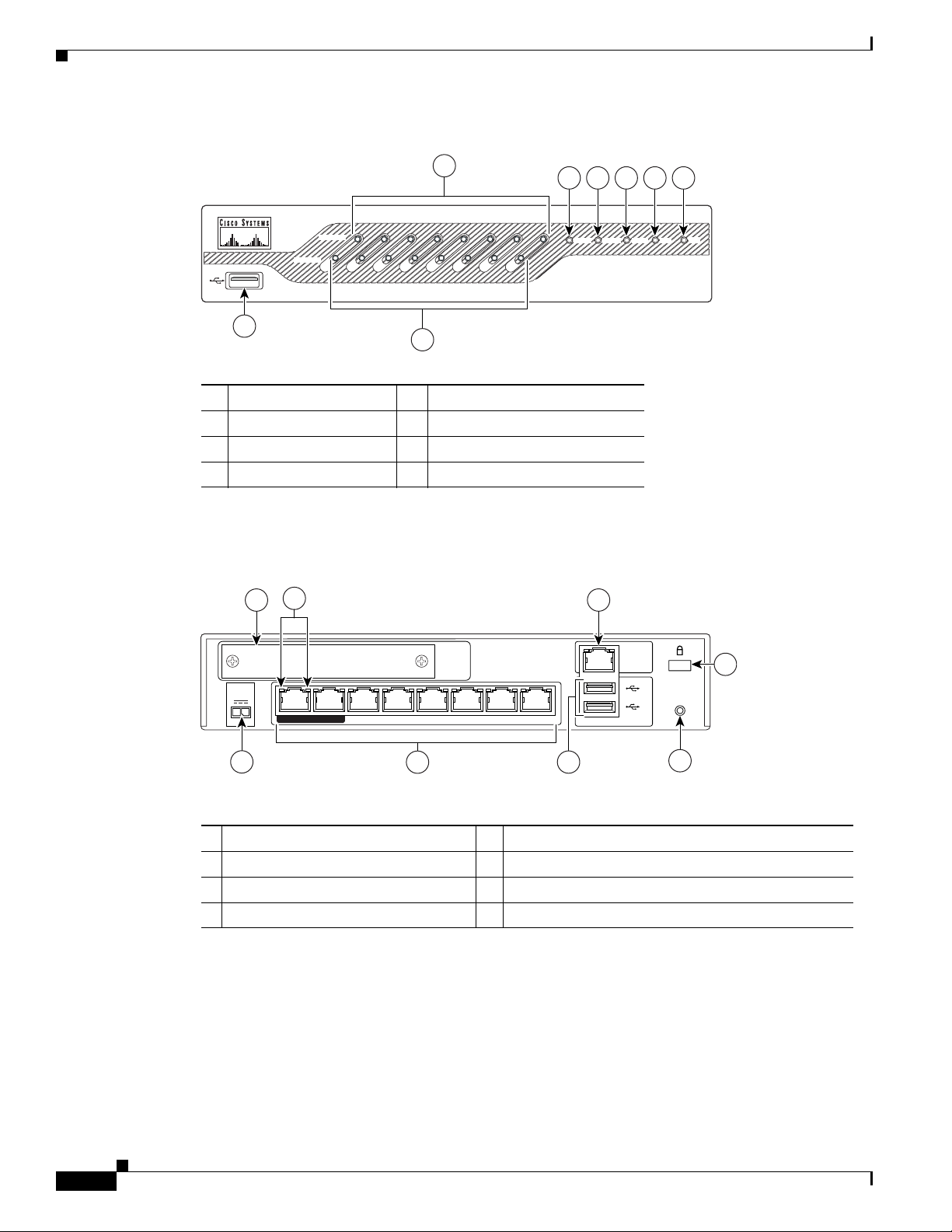
This section describes the front and rear panels. Figure 1-1 shows the front panel LEDs.
OL-18362-01
Cisco ASA 5505 Adaptive Security Appliance Hardware Installation Guide
1-1
Page 12
Product Overview
Chapter 1 Overview
Figure 1-1 Front Panel LEDs and Ports
3
4 7 8
5 6
LINK/ACT
100 MBPS
0
0 1 2 3 4 5 6 7
Power Status Active VPN SSC
Cisco ASA 5505 Series
Adaptive Security Appliance
1
2
1 USB 2.0 interface 5 Status
2 100 Mbps 6 Active
3 LINK/ACT LEDs 7 VPN
4 Power 8 SSC
Figure 1-2 shows the rear panel LEDs and Ports.
Figure 1-2 Rear Panel LEDs and Ports (AC Power Supply Model Shown)
3
2
5
153644
POWER
48
VDC
1
7
POWER over ETHERNET 6
Security
Services
Card Slot
543210
4
6
Console
1
2
8
RESET
153645
7
1 Power 48VDC 5 Console port
2 SSC slot 6 USB 2.0 interface
3 Network interface LEDs 7 Reset button
4 Network interfaces
1. Ports 6 and 7 are 15-Watt output PoE ports, used for devices, such as IP phones, which can be powered by the network
interface. They can also be used as regular Ethernet switch ports, just like the ports numbered 0 through 5.
1
8 Lock slot
1-2
Cisco ASA 5505 Adaptive Security Appliance Hardware Installation Guide
OL-18362-01
Page 13

Chapter 1 Overview
Memory Requirements
The default DRAM memory is 256MB and the default internal flash memory is 128MB for the
Cisco ASA 5505.
In a failover configuration, the two units must have the same hardware configuration They must be the
same model, have the same number and types of interfaces, and the same amount of RAM.
Note The two units do not have to have the same size Flash memory. If using units with different Flash
memory sizes in your failover configuration, make sure the unit with the smaller Flash memory has
enough space to accommodate the software image files and the configuration files. If it does not,
configuration synchronization from the unit with the larger Flash memory to the unit with the smaller
Flash memory will fail.
For more information, see the Cisco Security Appliance Command Line Configuration Guide.
Memory Requirements for the Software Version 8.3 and Later
Memory Requirements
For information on memory requirements for the adaptive security appliance for software Version 8.3 or
later, go to:
http://www.cisco.com/en/US/prod/collateral/vpndevc/ps6032/ps6094/ps6120/product_bulletin_c25-58
6414.html
OL-18362-01
Cisco ASA 5505 Adaptive Security Appliance Hardware Installation Guide
1-3
Page 14

Memory Requirements
Chapter 1 Overview
1-4
Cisco ASA 5505 Adaptive Security Appliance Hardware Installation Guide
OL-18362-01
Page 15

Preparing for Installation
The information in this guide applies to the Cisco ASA 5505 In this guide, references to “adaptive
security appliance” or security appliance apply to the Cisco ASA 5505 chassis unless specifically noted
otherwise.
This chapter describes the steps to follow before installing new hardware or performing hardware
upgrades, and includes the following sections:
• Installation Overview, page 2-1
• Safety Recommendations, page 2-1
• General Site Requirements, page 2-3
Installation Overview
To prepare for the installation of the chassis, perform the following steps:
CHA PTER
2
Step 1 Review the safety precautions outlined in the Regulatory Compliance and Safety Information for the
Cisco ASA 5500 Series document.
Step 2 Read the release notes for the respective software version.
Step 3 Unpack the chassis. An accessory kit ships with the chassis and includes the following items:
documentation, a product CD, a power cord (AC models only), two RJ-45 Ethernet cables, one RJ-45 to
DB-9 console cable, a rack-mounting kit, and four self-adhesive feet (for desktop mounting).
Step 4 Place the chassis on a stable work surface.
Safety Recommendations
Use the following guidelines and the information in the following sections to help ensure your safety and
protect the adaptive security appliance. The list of guidelines may not address all potentially hazardous
situations in your working environment, so be alert and exercise good judgement at all times.
Note If you need to remove the chassis cover to install a hardware component, such as additional memory or
an interface card, doing so does not affect your Cisco warranty. Upgrading the adaptive security
appliance does not require any special tools and does not create any radio frequency leaks.
OL-18362-01
Cisco ASA 5505 Adaptive Security Appliance Hardware Installation Guide
2-1
Page 16

Safety Recommendations
The safety guidelines are as follows:
• Keep the chassis area clear and dust-free before, during and after installation.
• Keep tools away from walk areas where you and others could fall over them.
• Do not wear loose clothing or jewelry, such as earrings, bracelets, or chains, that could get caught
in the chassis.
• Wear safety glasses if you are working under any conditions that might be hazardous to your eyes.
• Do not perform any action that creates a potential hazard to people or makes the equipment unsafe.
This section includes the following topics:
• Maintaining Safety with Electricity, page 2-2
• Preventing Electrostatic Discharge Damage, page 2-3
Maintaining Safety with Electricity
Chapter 2 Preparing for Installation
Warning
Before working on a chassis or working near power supplies, unplug the power cord on AC units;
disconnect the power at the circuit breaker on DC units.
Statement 12
Follow these guidelines when working on equipment powered by electricity:
• Before beginning procedures that require access to the interior of the chassis, locate the emergency
power-off switch for the room in which you are working. Then, if an electrical accident occurs, you
can act quickly to turn off the power.
• Do not work alone if potentially hazardous conditions exist anywhere in your work space.
• Never assume that power is disconnected from a circuit; always check the circuit.
• Look carefully for possible hazards in your work area, such as moist floors, ungrounded power
extension cables, frayed power cords, and missing safety grounds.
• If an electrical accident occurs, proceed as follows:
–
Use caution; do not become a victim yourself.
–
Disconnect power from the system.
–
If possible, send another person to get medical aid. Otherwise, assess the condition of the victim
and then call for help.
–
Determine if the person needs rescue breathing or external cardiac compressions; then take
appropriate action.
• Use the adaptive security appliance chassis within its marked electrical ratings and product usage
instructions.
• Install the adaptive security appliance in compliance with local and national electrical codes as listed
in the Regulatory Compliance and Safety Information for the Cisco ASA 5500 Series document.
2-2
• The adaptive security appliance models equipped with AC-input power supplies are shipped with a
3-wire electrical cord with a grounding-type plug that fits only a grounding-type power outlet. Do
not circumvent this safety feature. Equipment grounding should comply with local and national
electrical codes.
Cisco ASA 5505 Adaptive Security Appliance Hardware Installation Guide
OL-18362-01
Page 17

Chapter 2 Preparing for Installation
Preventing Electrostatic Discharge Damage
Electrostatic discharge (ESD) can damage equipment and impair electrical circuitry. ESD damage occurs
when electronic components are improperly handled and can result in complete or intermittent failures.
• Always follow ESD-prevention procedures when removing and replacing components. Ensure that
the chassis is electrically connected to earth ground. Wear an ESD-preventive wrist strap, ensuring
that it makes good skin contact. Connect the grounding clip to an unpainted surface of the chassis
frame to safely ground ESD voltages. To properly guard against ESD damage and shocks, the wrist
strap and cord must operate effectively. If no wrist strap is available, ground yourself by touching
the metal part of the chassis.
• For safety, periodically check the resistance value of the antistatic strap, which should be between
1 and 10 megohms (Mohms).
General Site Requirements
The topics in this section describe the requirements your site must meet for safe installation and
operation of your system. Ensure that your site is properly prepared before beginning installation.
General Site Requirements
This section includes the following topics:
• Site Environment, page 2-3
• Preventive Site Configuration, page 2-3
• Power Supply Considerations, page 2-4
• Configuring Equipment Racks, page 2-4
Site Environment
Place the chassis on a desktop or mount it on a rack. The location of the chassis and the layout of the
equipment rack or wiring room are extremely important for proper system operation. Equipment placed
too close together, inadequate ventilation, and inaccessible panels can cause system malfunctions and
shutdowns, and can make the chassis maintenance difficult.
For information on physical specifications, see table 7 at the following url:
http://www.cisco.com/en/US/prod/collateral/vpndevc/ps6032/ps6094/ps6120/product_data_sheet0900a
ecd802930c5.html.
When planning the site layout and equipment locations, keep in mind the precautions described in the
next section “Preventive Site Configuration, page 2-3,” to help avoid equipment failures and reduce the
possibility of environmentally caused shutdowns. If you are currently experiencing shutdowns or
unusually high error rates with your existing equipment, these precautions may help you isolate the
cause of failures and prevent future problems.
Preventive Site Configuration
The following precautions will help plan an acceptable operating environment for the chassis and avoid
environmentally caused equipment failures:
OL-18362-01
Cisco ASA 5505 Adaptive Security Appliance Hardware Installation Guide
2-3
Page 18

General Site Requirements
• Electrical equipment generates heat. Ambient air temperature might not be adequate to cool
equipment to acceptable operating temperatures without adequate circulation. Ensure that the room
in which you operate your system has adequate air circulation.
• Always follow the ESD-prevention procedures described previously to avoid damage to equipment.
Damage from static discharge can cause immediate or intermittent equipment failure.
• Ensure that the chassis top panel is secure. The chassis is designed to allow cooling air to flow
effectively within it. An open chassis allows air leaks, which may interrupt and redirect the flow of
cooling air from the internal components.
Power Supply Considerations
For information on power supply considerations including environmental operating ranges and power
requirements, see table 7 at the following url:
http://www.cisco.com/en/US/prod/collateral/vpndevc/ps6032/ps6094/ps6120/product_data_sheet0900a
ecd802930c5.html
Observe the following considerations:
Chapter 2 Preparing for Installation
• Check the power at the site before installing the chassis to ensure that the power is “clean” (free of
spikes and noise). Install a power conditioner if necessary, to ensure proper voltages and power
levels in the source voltage.
• Install proper grounding for the site to avoid damage from lightning and power surges.
• In a chassis equipped with an AC-input power supply, use the following guidelines:
–
The chassis does not have a user-selectable operating range. Refer to the label on the chassis for
the correct AC-input power requirement.
–
Several styles of AC-input power supply cords are available; make sure you have the correct
style for your site.
–
Install an uninterruptible power source for your site, if possible.
–
Install proper site grounding facilities to guard against damage from lightning or power surges.
Configuring Equipment Racks
For information on physical specifications, see table 7 at the following url:
http://www.cisco.com/en/US/prod/collateral/vpndevc/ps6032/ps6094/ps6120/product_data_sheet0900a
ecd802930c5.html.
2-4
Cisco ASA 5505 Adaptive Security Appliance Hardware Installation Guide
OL-18362-01
Page 19

Installing the Cisco ASA 5505
Installing the Chassis
This section contains the following topics:
• Connecting the Interface Cables, page 3-1
• Powering on the Cisco ASA 5505, page 3-3
• Installing a Cable Lock, page 3-4
• Rack or Wall Mounting the Cisco ASA 5505, page 3-4
Connecting the Interface Cables
This section describes how to connect the cables to the Ethernet and Console ports.
CHA PTER
3
Warning
Caution Read the safety warnings in the Regulatory Compliance and Safety Information for the Cisco ASA 5505
Step 1 Place the chassis on a flat, stable surface.
Step 2 Before connecting a computer or terminal to the ports, check to determine the baud rate of the serial port. The
Step 3 Connect the cables to the ports.
Only trained and qualified personnel should install, replace, or service this equipment. Statement 49
Adaptive Security Appliance and follow proper safety procedures when performing these steps.
To connect cables to the ports perform the following steps:
baud rate must match the default baud rate (9600 baud) of the Console port of the adaptive security
appliance. Set up the terminal as follows: 9600 baud (default), 8 data bits, no parity, 1 stop bits, and Flow
Control (FC) = Hardware.
OL-18362-01
Cisco ASA 5505 Adaptive Security Appliance Hardware Installation Guide
3-1
Page 20

Connecting the Interface Cables
a. Ethernet ports
Step 1 Connect Port 0, the outside Ethernet port, to the public network, that is, the Internet:
Note By default, switch port 0/0 is the outside port. If needed you can change the inside and outside
Step 2 Connect your network devices with an Ethernet cable to one of the inside ports (numbered 1 through 7).
If you are connecting any PoE devices, connect them to one of the switch ports that support PoE (ports
numbered 6 and 7).
Step 3 Check the LINK LED to verify that the network devices have basic connectivity to the Cisco ASA 5505
on one of the inside ports (numbered 0 through 7). When connectivity is established, the LINK LED on
the front panel of the Cisco ASA 5505 lights up solid green.
Figure 3-1 Connecting Cables to Network Interfaces
Chapter 3 Installing the Cisco ASA 5505
ports assignments later.
Step 4
power
48
VDC
7 POWER over ETHERNET 6
Security
Services
Card Slot
543210
Console
1
2
RESET
153646
1
2
1 RJ-45 Ethernet ports 2 RJ-45 connector
Connect the power cord to the adaptive security appliance and plug the other end to the power source.
For information on powering on the chassis, see the “Powering on the Cisco ASA 5505” section on
page 3-3
3-2
Cisco ASA 5505 Adaptive Security Appliance Hardware Installation Guide
OL-18362-01
Page 21

Chapter 3 Installing the Cisco ASA 5505
b. Console port
You can access the command line for administration using the console port on theCisco ASA 5505. To
connect to the console port and run a serial terminal emulator on a PC or workstation, perform the
following steps:
Step 1 Plug one end of the PC terminal adapter into a standard 9-pin PC serial port on your PC.
Step 2 Plug one end of the blue console cable into the PC terminal adapter.
Step 3 Plug the other end of the blue console cable into the Console port.
Step 4 Configure the PC terminal emulation software or terminal for 9600 baud, 8 data bits, no parity, and 1
stop bit.
Figure 3-2 Connecting to the Console Cable
Powering on the Cisco ASA 5505
Security
Services
Card Slot
power
48
VDC
7
POWER over ETHERNET
6
54 3210
1 RJ-45 Console port 2 RJ-45 to DB-9 console cable
Powering on the Cisco ASA 5505
To power on the Cisco ASA 5505, perform the following steps:
Step 1 Connect the power supply with the power cable.
Step 2 Connect the small, rectangular connector of the power supply cable to the power connector on the rear.
Console
1
RESET
2
1
2
153643
OL-18362-01
Step 3 Connect the AC power connector of the power supply input cable to an electrical outlet.
Note The Cisco ASA 5505 does not have a power switch. Completing Step 3 powers on the device.
Step 4 Check the power LED; if it is solid green, then the device is powered on.
Cisco ASA 5505 Adaptive Security Appliance Hardware Installation Guide
3-3
Page 22

Installing a Cable Lock
Note The light will be solid green, only for 100Mbps devices.
Installing a Cable Lock
The Cisco ASA 5505 includes a slot that accepts standard desktop cable locks to provide physical
security. The cable lock is not included.
To install a cable lock, perform the following steps:
Step 1 Follow the directions from the manufacturer for attaching the other end of the cable for securing the
Cisco ASA 5505.
Step 2 Attach the cable lock to the lock slot on the back panel of the Cisco ASA 5505.
Chapter 3 Installing the Cisco ASA 5505
Rack or Wall Mounting the Cisco ASA 5505
Warning
To prevent bodily injury when mounting or servicing this unit in a rack, you must take special
precautions to ensure that the system remains stable. The following guidelines are provided to ensure
your safety:
mounting this unit in a partially filled rack, load the rack from the bottom to the top with the heaviest component
at the bottom of the rack. If the rack is provided with stabilizing devices, install the stabilizers before mounting
or servicing the unit in the rack.
The following information can help plan equipment rack installation:
• Allow clearance around the rack for maintenance.
• If the rack contains stabilizing devices, install the stabilizers prior to mounting or servicing the unit
in the rack.
• When mounting a device in an enclosed rack, ensure adequate ventilation. Do not overcrowd an
enclosed rack. Make sure that the rack is not congested, because each unit generates heat.
• When mounting a device in an open rack, make sure that the rack frame does not block the intake
or exhaust ports.
• If the rack contains only one unit, mount the unit at the bottom of the rack.
• If the rack is partially filled, load the rack from the bottom to the top, with the heaviest component
at the bottom of the rack.
This unit should be mounted at the bottom of the rack if it is the only unit in the rack. When
Statement 1006
3-4
This section contains the following topics:
• Mounting the Chassis, page 3-5
• Installing and Wall-Mounting the Cisco ASA 5505 FIPS Enclosure, page 3-11
Cisco ASA 5505 Adaptive Security Appliance Hardware Installation Guide
OL-18362-01
Page 23

Chapter 3 Installing the Cisco ASA 5505
Mounting the Chassis
You can wall-mount or rack-mount the adaptive security appliance. The part number for ordering a
wall-mount kit for the adaptive security appliance is ASA-5505-WALL-MNT= , the part number for
ordering a rack-mount kit for the adaptive security appliance is ASA5505-RACK-MNT= . This section
includes the following topics:
• Wall-Mounting the Chassis, page 3-5
• Rack-Mounting the Chassis, page 3-7
Wall-Mounting the Chassis
To wall-mount the chassis, perform the following steps:
Step 1 Choose a wall where you would like to mount the adaptive security appliance.
Step 2 Using the wall-mounting bracket as a template, use a pencil to mark the location for the four plastic anchors,
used to secure the adaptive security appliance to the wall. Make sure all the pencil marks are located in the
center as shown in Figure 3-10.
Rack or Wall Mounting the Cisco ASA 5505
Figure 3-3 Wall-Mounting Bracket
1
1
2
3
2
2
3
2
1
Screws
(4)
Anchors
(4)
Sheet metal screws
(3)
191805
1 M3 x 12 screws 3 Plastic anchors for vertical mounting (optional)
2 Plastic anchors
OL-18362-01
Step 3 Drill a hole on the wall at each mark you made for the location for the plastic anchors.
Step 4 Press the four plastic anchors into the holes.
Step 5 Screw the four screws provided in the accessory kit into the anchors, but not all the way. Allow them to
protrude about 1/8-inch (0.317 cm).
Cisco ASA 5505 Adaptive Security Appliance Hardware Installation Guide
3-5
Page 24

Rack or Wall Mounting the Cisco ASA 5505
Step 6 Remove the three screws from the bottom of the adaptive security appliance as shown in Figure 3-13.
Discard these screws as you will not need them.
Step 7 Place the wall-mount bracket on the adaptive security appliance. Use the three screws provided in the
accessory kit to screw the wall-mount bracket to the adaptive security appliance as shown in Figure 3-13.
Figure 3-4 Removing and Replacing the Screws
Chapter 3 Installing the Cisco ASA 5505
Step 8
191806
Pick up the adaptive security appliance with the wall-mount bracket facing the wall, align the screws in the
anchors with the holes in the brackets.
3-6
Cisco ASA 5505 Adaptive Security Appliance Hardware Installation Guide
OL-18362-01
Page 25

Chapter 3 Installing the Cisco ASA 5505
Step 9 Allowing the screws in the anchors to go through the holes in the brackets, mount and slide down the
adaptive security appliance.
Figure 3-5 Mounting the Cisco ASA 5505 Chassis
Rack or Wall Mounting the Cisco ASA 5505
1
1 Screws
Step 10
Connect the interface cables.
For information on installing the cables
Rack-Mounting the Chassis
To rack-mount the adaptive security appliance chassis, perform the following steps:
Step 1 Remove the three screws from the bottom of the adaptive security appliance as shown in Figure 3-13.
Discard these screws as you will not need them.
Step 2 Place the wall-mount bracket on the adaptive security appliance. Use the three screws provided in the
accessory kit to screw the wall-mount bracket to the adaptive security appliance as shown in Figure 3-13.
190683
, see the “Connecting the Interface Cables” section.
OL-18362-01
Cisco ASA 5505 Adaptive Security Appliance Hardware Installation Guide
3-7
Page 26

Rack or Wall Mounting the Cisco ASA 5505
Step 3 Place the wall-mount bracket with the adaptive security appliance attached to it on the rack mount tray
as shown in Figure 3-6.
Figure 3-6 Placing the Device on the Rack Mount Tray
LINK/ACT
100 MBPS
0
0
1
2
3
4
1
Power Status
7
Active VPN SSC
Cisco ASA 5505
Adaptive Security Appliance
Series
LINK/ACT
100 MBPS
0
0
1
2
3
4
Power Status
7
Active
Cisco ASA 5505
Adaptive Security Appliance
Series
5
6
5
6
2
2
1
VPN SSC
Chapter 3 Installing the Cisco ASA 5505
3
4
5
4
191807
Step 4
1 Wall-mount bracket 2 Cisco ASA 5505 chassis 5 Ve l cr o
3 Cable manager 4 Power supply
Place the power supply adapter on the rack-mount tray and use the velcro provided to hold it in place as
shown in Figure 3-6.
3-8
Cisco ASA 5505 Adaptive Security Appliance Hardware Installation Guide
OL-18362-01
Page 27

Chapter 3 Installing the Cisco ASA 5505
Step 5 Screw in the security bracket to the front of the rack mount as shown in Figure 3-7, to hold it in place.
Rack or Wall Mounting the Cisco ASA 5505
Figure 3-7 Attaching the Security Bracket
LINK/ACT
100 MBPS
0
0
1
2
3
4
5
6
7
Cisco ASA 5505
sco ASA 5505
Power Status
Active VPN SSC
Series
Adaptive Security Appliance
atus
Adaptive Security Appliance
1
Active
Series
0
VPN
SSC
2
LINK/ACT
100 MBPS
0
1
2
3
Power
4
Status
6
7
Cisco ASA 5505
Adaptive Security Appliance
Active
VPN
SSC
Series
191809
5
0
1 Security bracket 2 Screw
OL-18362-01
Cisco ASA 5505 Adaptive Security Appliance Hardware Installation Guide
3-9
Page 28

Rack or Wall Mounting the Cisco ASA 5505
Step 6 Attach the rack-mount tray to the rack using the supplied screws, as shown in Figure 3-8.
Chapter 3 Installing the Cisco ASA 5505
Figure 3-8 Attaching the Rack Mount Tray to the Rack
LINK/A
CT
100 MBPS
0
0
1
2
Power
3
Status
4
Active
5
VPN
6
7
Cisco ASA 5505
Adaptive Security Appliance
SSC
Ser
ies
100 MBPS
0
CISCO
ASA
5530
Adaptive Security Appliance
SE
LINK/A
CT
0
1
2
3
RIES
Pow
er
Status
4
Act
ive
5
VPN
6
7
Cisco ASA 5505
Adaptive Security Appliance
SSC
Series
191808
To remove the chassis from the rack, remove the screws that attach the chassis to the rack, and then
remove the chassis.
3-10
Cisco ASA 5505 Adaptive Security Appliance Hardware Installation Guide
OL-18362-01
Page 29

Chapter 3 Installing the Cisco ASA 5505
Rack or Wall Mounting the Cisco ASA 5505
Installing and Wall-Mounting the Cisco ASA 5505 FIPS Enclosure
Figure 3-9 shows the FIPS enclosure for the Cisco ASA 5505.
Figure 3-9 FIPS Enclosure
272363
To install and wall-mount the Cisco ASA 5505 FIPS enclosure, perform the following steps:
Step 1 Choose a wall where you would like to mount the Cisco ASA 5505.
Step 2 Using the FIPS enclosure as a template, use a pencil to mark the location for the four plastic anchors, used
to secure the adaptive security appliance to the wall. Make sure all the pencil marks are located in the center
as shown in Figure 3-10.
OL-18362-01
Cisco ASA 5505 Adaptive Security Appliance Hardware Installation Guide
3-11
Page 30

Rack or Wall Mounting the Cisco ASA 5505
Figure 3-10 Bottom View of the FIPS Enclosure
1
Chapter 3 Installing the Cisco ASA 5505
1
2
3
2
2
3
2
272365
1
1 M3 x 12 screws 3 Plastic anchors for vertical mounting (optional)
2 Plastic anchors
Step 3
Step 4 Press the four plastic anchors into the holes.
Step 5 Screw the four screws provided in the accessory kit into the anchors, but not all the way. Allow them to
Drill a hole on the wall at each mark you made for the location for the plastic anchors.
protrude about 1/8-inch (0.317 cm).
You must apply three tamper evident labels. Tamper evident labels are inclued in the FIPS kit,
Cisco-FIPS-KIT=. Clean the chassis of any grease, dirt, or oil before applying the tamper evident labels.
Alcohol-based cleaning pads are recommended for this purpose.
3-12
Step 6 Apply the first tamper evident label as shown in Figure 3-11.
Figure 3-11 Cisco ASA 5505 Tamper Evident Label Placement
1
Security
Services
Card Slot
POWER
48
VDC
7
POWER over ETHERNET 6
543210
1 Ta m per lab e l
Cisco ASA 5505 Adaptive Security Appliance Hardware Installation Guide
Console
1
2
RESET
250576
OL-18362-01
Page 31

Chapter 3 Installing the Cisco ASA 5505
Step 7 Remove the three screws from the bottom of the Cisco ASA 5505 as shown in Figure 3-12.
Figure 3-12 Removing the Screws
Rack or Wall Mounting the Cisco ASA 5505
250575
Step 8 Slide the ASA 5540 into the FIPS enclosure as shown in Figure 3-13.
Figure 3-13 Sliding the Cisco ASA 5505 Chassis into the FIPS Enclosure
CO ASA 5505
CIS
Securi
Adaptive
Step 9
Turn the FIPS enclosure with the chassis securely inside and use the three screws you removed in Step 6
to screw the FIPS enclosure to the Cisco ASA 5505.
Appliance
ty
IES
SER
272362
OL-18362-01
Step 10 Apply the second tamper evident label over the screw as shown in Figure 3-14.
Cisco ASA 5505 Adaptive Security Appliance Hardware Installation Guide
3-13
Page 32

Rack or Wall Mounting the Cisco ASA 5505
Figure 3-14 Tamper Evident Label Applied Over the Screw
Chapter 3 Installing the Cisco ASA 5505
250578
1
Step 11
1 Ta m per lab e l
The third tamper evident label should be placed so that the one half of the tamper evident label covers
the enclosure and the other half covers the Cisco ASA 5505 chassis as shown in Figure 3-15.
Figure 3-15 Tamper Evident Label Applied Over the Chassis and the FIPS Enclosure
1
0
LINK/AC
T
100
MB
PS
0
1
2
3
4
5
6
7
Pow
er
Cis
co ASA 5505
Status
Adap
tiv
Act
ive
VPN
Series
e Security Appliance
SSC
250577
3-14
1 Ta m per lab e l
Cisco ASA 5505 Adaptive Security Appliance Hardware Installation Guide
OL-18362-01
Page 33

Chapter 3 Installing the Cisco ASA 5505
Step 12 Pick up the Cisco ASA 5505 with the FIPS enclosure facing the wall, align the screws in the anchors with
the holes in the enclosure.
Step 13 Allowing the screws in the anchors to go through the holes in the enclosure, mount and slide down the
Cisco ASA 5505 as shown in Figure 3-16.
Figure 3-16 Mounting the Cisco ASA 5505 Chassis
Rack or Wall Mounting the Cisco ASA 5505
Step 14
272361
1 Screws
Connect the interface cables.
For information on installing the cables
1
272361
, see the “Connecting the Interface Cables” section.
OL-18362-01
Cisco ASA 5505 Adaptive Security Appliance Hardware Installation Guide
3-15
Page 34

Rack or Wall Mounting the Cisco ASA 5505
Chapter 3 Installing the Cisco ASA 5505
3-16
Cisco ASA 5505 Adaptive Security Appliance Hardware Installation Guide
OL-18362-01
Page 35

CHA PTER
Maintenance and Upgrade Procedures
This chapter describes how to install the chassis on the wall or rack, remove and replace the chassis
cover, the power supply, and the CompactFlash. This chapter includes the following sections:
• Removing and Replacing the Chassis Cover, page 4-1
• Replacing the Lithium Battery, page 4-3
• Installing and Replacing the SSC, page 4-4
• Upgrading Memory, page 4-6
Removing and Replacing the Chassis Cover
This section describes how to remove and replace the chassis cover. This section includes the following
topics:
• Working in an ESD Environment, page 4-1
4
• Removing the Chassis Cover, page 4-2
• Replacing the Chassis Cover, page 4-3
Working in an ESD Environment
Electrostatic discharge (ESD) can damage equipment and impair electrical circuitry. ESD damage occurs
when electronic components are improperly handled and can result in complete or intermittent failures.
Always follow ESD-prevention procedures when you remove and replace components. Ensure that the
chassis is electrically connected to earth ground. Wear an ESD-preventive wrist strap, ensuring that it
makes good skin contact. Connect the grounding clip to an unpainted surface of the chassis frame to
safely ground unwanted ESD voltages. To guard against ESD damage and shocks, the wrist strap and
cord must operate properly. If no wrist strap is available, ground yourself by touching the metal part of
the chassis.s
OL-18362-01
Cisco ASA 5505 Adaptive Security Appliance Hardware Installation Guide
4-1
Page 36

Removing and Replacing the Chassis Cover
Removing the Chassis Cover
To remove the chassis cover, perform the following steps:
Note Removing the chassis cover does not affect Cisco warranty. Upgrading the adaptive security appliance
does not require any special tools and does not create any radio frequency leaks.
Step 1 Read the Regulatory Compliance and Safety Information for the Cisco ASA 5500 Series document.
Step 2 Power off the adaptive security appliance.
Chapter 4 Maintenance and Upgrade Procedures
Warning
Before working on a system that has an On/Off switch, turn OFF the power and unplug the power cord.
Statement 1
Step 3 Turn the chassis upside down so that the top of the chassis is resting on a flat surface, and the front of
the chassis is facing toward you.
Step 4 Remove the three screws located on the bottom of the chassis as shown in Figure 4-1.
Figure 4-1 Removing the Screws
250575
4-2
Step 5
Return the chassis to the upright position. Note that the chassis is comprised of two sections: top and
bottom.
Step 6 Hold both sides of the top section, at the base of the appliance in the rear and pull outward while gently
lifting upward.
Cisco ASA 5505 Adaptive Security Appliance Hardware Installation Guide
OL-18362-01
Page 37

Chapter 4 Maintenance and Upgrade Procedures
Replacing the Chassis Cover
Caution Do not operate the adaptive security appliance without the chassis cover installed. The chassis cover
protects the internal components, prevents electrical shorts, and provides proper air-flow for cooling the
electronic components.
To replace the chassis cover on the adaptive security appliance, perform the following steps:
Step 1 Place the chassis on a secure surface with the front panel facing you.
Step 2 Hold the chassis cover so that the rear of the chassis cover are aligned with the chassis bottom.
Step 3 Lower the front of the cover onto the chassis, making sure that the side tabs of the cover fit under the
side panels of the chassis.
Step 4 Slide the chassis cover toward the front, making sure that the cover tabs fit under the back panel, and the
back panel tabs fit under the chassis cover.
Step 5 Secure the chassis cover with the screw you set aside earlier.
Step 6 Reconnect the network interface cables.
Replacing the Lithium Battery
Step 7 Reconnect the power cord to the power outlet to power on the adaptive security appliance.
Replacing the Lithium Battery
This section describes how to remove and replace the lithium battery in the adaptive security appliance.
The lithium battery is a field-replaceable unit (FRU).
Warning
Step 1 Remove the chassis cover as described in the “Removing the Chassis Cover” section on page 4-2.
Step 2 Slide the metal clip back and pull the battery out.
Danger of explosion exists if the lithium battery is incorrectly replaced. Replace only with the same
or equivalent type recommended by the manufacturer. Dispose of used batteries according to the
manufacturer's instructions.
Statement 33
To remove and replace the battery in the adaptive security appliance, perform the following steps:
OL-18362-01
Cisco ASA 5505 Adaptive Security Appliance Hardware Installation Guide
4-3
Page 38

Installing and Replacing the SSC
Figure 4-2 Cisco ASA 5505 Lithium Battery Location
Security
Services
Card Slot
2
1 Battery 2 Metal clip
Chapter 4 Maintenance and Upgrade Procedures
2
1
191733
1
0
Console
1
2
RESET
Step 3
Place the used battery aside.
Step 4 Replace the battery with a compactible Lithium CR-2032 battery (which is available at your local electronics
or drug store), by sliding the metal clip back and sliding the battery into place.
Step 5 Replace the chassis cover as described in the “Replacing the Chassis Cover” section on page 4-3.
Installing and Replacing the SSC
This section describes how to install and replace the Security Services Card (SSC) . This section includes
the following topics:
• Installing an SSC, page 4-5
• Replacing an SSC, page 4-6
Figure 4-3 lists the SSC LEDs.
Figure 4-3 SSC LEDs
1
4-4
Cisco ASA SSC-05
Cisco ASA 5505 Adaptive Security Appliance Hardware Installation Guide
STAT US
251164
OL-18362-01
Page 39

Chapter 4 Maintenance and Upgrade Procedures
Table 4-1 describes the SSC LEDs.
Table 4-1 SSC LEDs
LED Color State Description
1 STATUS Green Flashing
Installing an SSC
To install a new SSC for the first time, perform the following steps:
Step 1 Power off the adaptive security appliance.
Step 2 Locate the grounding strap from the accessory kit and fasten it to your wrist so that it contacts your bare
skin. Attach the other end to the chassis.
Step 3 Remove the two screws (as shown in Figure 4-4) at the left rear end of the chassis, and remove the slot
cover.
Solid
Installing and Replacing the SSC
The system is booting.
The system has passed power-up diagnostics.
Step 4
Figure 4-4 Removing the Screws from the Slot Cover
POWER
48
VDC
7
POWER over ETHERNET
6
54 3210
Security
Services
Card Slot
Console
1
2
Insert the SSC into the slot opening as shown in Figure 4-5.
Figure 4-5 Inserting the SSC into the Slot
POWER
48
VDC
7
POWER over ETHERNET
C
i
sc
o
A
S
A
S
S
C
-05
S
T
A
T
U
S
6
RESET
Security
Services
Card Slot
543210
Console
1
2
251165
RESET
251166
OL-18362-01
Step 5 Attach the screws to secure the SSC to the chassis.
Step 6 Power on the adaptive security appliance.
Step 7 Check the LEDs. If the SSC is installed properly the STATUS LED flashes green.
Step 8 Connect one end of the RJ-45 cable to the port and the other end of the cable to your network devices.
Cisco ASA 5505 Adaptive Security Appliance Hardware Installation Guide
4-5
Page 40

Upgrading Memory
Replacing an SSC
To replace an existing SSC, perform the following steps:
Step 1 Enter the hw-mod mod 1 shut command in privileged EXEC mode. Verify if the module is down by
checking the LEDs.
Step 2 Locate the grounding strap from the accessory kit and fasten it to your wrist so that it contacts your bare
skin. Attach the other end to the chassis.
Step 3 Remove the two screws (as shown in Figure 4-4) at the left rear end of the chassis.
Step 4 Remove the SSC. Set it aside.
Step 5 Replace the existing card by inserting the new SSC through the slot opening as shown in Figure 4-5.
Step 6 Attach the screws to secure the SSC to the chassis.
Step 7 Enter the hw-mod mod 1 reset command in privileged EXEC mode to reset the SSC.
Step 8 Check the LEDs. If the SSC is installed properly, the STATUS LED flashes green.
Step 9 Connect one end of the RJ-45 cable to the port and the other end of the cable to your network devices.
Chapter 4 Maintenance and Upgrade Procedures
Upgrading Memory
The memory upgrade kit, ASA5505-MEM-512=, allows you to upgrade the Cisco ASA 5505 to 512 MB
of memory. To determine how much memory your adaptive security appliance has, use the show version
command:
hostname# show version
Cisco Adaptive Security Appliance Software Version 8.0(0)
Device Manager Version 6.0(0)
Compiled on Mon 16-April-07 03:29 by root
System image file is "disk0:/cdisk.bin"
Config file at boot was "disk0:/main_backup.cfg"
hostname up 2 days 10 hours
failover cluster up 2 days 11 hours
Hardware: ASA5505, 256 MB RAM, CPU Pentium 4 Celeron 2000 MHz
BIOS Flash M50FW016 @ 0xffe00000, 2048KB
Table 2 lists the memory for the Cisco ASA 5505.
Table 2 Memory Upgrade
Model Current Memory Upgrade to
Cisco ASA 5505 256 MB 512 MB
4-6
Cisco ASA 5505 Adaptive Security Appliance Hardware Installation Guide
OL-18362-01
Page 41

Chapter 4 Maintenance and Upgrade Procedures
This section describes how to remove and install the memory module on the adaptive security appliance.
This section includes the following topics:
• Removing the DIMM, page 4-7
• Installing the DIMM, page 4-8
Removing the DIMM
To remove the memory module, perform the following steps:
Step 1 Determine the location of the memory sockets, see Figure 6.
Figure 6 System Memory Location in the Cisco ASA 5505
Upgrading Memory
1
2
3
281045
1 DIMM
2 CompactFlash
3 Battery
Step 2 Locate the wrist grounding strap and connect one end to the adaptive security appliance, and securely
attach the other to your wrist so it contacts your bare skin. See,
“Working in an ESD Environment” for
more information.
Note Handle the edges of the DIMM only; avoid touching the memory modules, pins, or traces (the
metal fingers along the connector edge of the DIMM), along the connector edge.
OL-18362-01
Cisco ASA 5505 Adaptive Security Appliance Hardware Installation Guide
4-7
Page 42

Upgrading Memory
Step 3 Pull the latches away from the DIMM at both ends. See Figure 8.
Step 4 When both ends of the DIMM are released from the socket, grasp the ends of the DIMM with your thumb
Chapter 4 Maintenance and Upgrade Procedures
To prevent ESD damage, handle DIMMs as shown in Figure 7.
Figure 7 Handling a DIMM
33115
and forefinger and pull the DIMM completely out of the socket.
Figure 8 Releasing the DIMM Latches
Step 5 Place the DIMM in an antistatic container to protect it from ESD damage.
Installing the DIMM
To install the memory module, perform the following steps:
Step 1 Make sure that both latches on the DIMM connector are open.
Step 2 Remove a new DIMM from the antistatic container.
2
1
1
203845
4-8
The DIMM is designed in such a way that the connector will fit only one way.
Step 3 Hold the DIMM component side up, with the connector edge away from you. Line up the notch in the
connector traces with the notch in the socket on the board.
Step 4 Carefully insert the connector edge into the socket and firmly press the DIMM into the socket until both
latches rotate to the close position against the DIMM. See Figure 9.
Cisco ASA 5505 Adaptive Security Appliance Hardware Installation Guide
OL-18362-01
Page 43

Chapter 4 Maintenance and Upgrade Procedures
Figure 9 Inserting the DIMM
2 2
Caution When inserting DIMMs, use firm but not excessive pressure. You can cause damage to the socket.
When you finish installing new memory, replace the chassis cover.
Upgrading Memory
1
242881
Verifying the Memory Upgrade
You can verify that the memory upgrade has been completed successfully by entering the show version
command:
hostname# show version
Cisco Adaptive Security Appliance Software Version 8.0(0)
Device Manager Version 6.0(0)
Compiled on Mon 16-April-07 03:29 by root
System image file is "disk0:/cdisk.bin"
Config file at boot was "disk0:/main_backup.cfg"
hostname up 2 days 10 hours
failover cluster up 2 days 11 hours
Hardware: ASA5505, 512 MB RAM, CPU Pentium 4 Celeron 2000 MHz
BIOS Flash M50FW016 @ 0xffe00000, 2048KB
OL-18362-01
Cisco ASA 5505 Adaptive Security Appliance Hardware Installation Guide
4-9
Page 44

Upgrading Memory
Chapter 4 Maintenance and Upgrade Procedures
4-10
Cisco ASA 5505 Adaptive Security Appliance Hardware Installation Guide
OL-18362-01
Page 45

Cable Pinouts
This appendix describes pinout information for 10/100/1000BaseT ports, console and the RJ-45 to DB-9
ports, and the Management 10/100/1000 Ethernet port, and includes the following sections:
• 10/100/1000BaseT Connectors, page 1-1
• Console Port (RJ-45), page 1-2
• RJ-45 to DB-9, page 1-4
• MGMT 10/100/1000 Ethernet Port, page 1-4
• Gigabit and Fibre Channel Ports, page 1-5
10/100/1000BaseT Connectors
The adaptive security appliance supports 10/100/1000BaseT ports. You must use at least a Category 5
cable for 100/1000baseT operations, but a Category 3 cable can be used for 10BaseT operations.
APPENDIX
1
The 10/100/1000BaseT ports use standard RJ-45 connectors and supports MDI and MDI-X connectors.
Ethernet ports normally use MDI connectors and Ethernet ports on a hub normally use an MDI-X connector.
Use an Ethernet straight-through cable to connect an MDI to an MDI-X port. Use a cross-over cable to
connect an MDI to an MDI port, or an MDI-X to an MDI-X port.
Figure 1-1 shows the 10BaseT and the 100BaseTX connector (RJ-45).
Figure 1-1 10/100 Port Pinouts
231 45678Pin Label
1
2
3
4
5
6
7
8
RD+
RD-
TD+
NC
NC
TD-
NC
NC
H5318
OL-18362-01
Cisco ASA 5505 Adaptive Security Appliance Hardware Installation Guide
1-1
Page 46

Console Port (RJ-45)
Appendix 1 Cable Pinouts
Figure 1-2 shows the 10BaseT, 100BaseTX, and 1000BASE-T connector (RJ-45).
Figure 1-2 10/100/1000 Port Pinouts
231 45678Pin Label
1
2
3
4
5
6
7
8
TP0+
TP0-
TP1+
TP2+
TP2-
TP1-
TP3+
TP3-
Console Port (RJ-45)
Cisco products use the following types of RJ-45 cables:
• Straight-through
• Crossover
Note Cisco does not provide these cables; they are widely available from other sources.
Figure 1-3 shows the RJ 45 cable.
Figure 1-3 RJ-45 Cable
60915
1-2
8 7 6 5 4 3 2 1
RJ-45 connector
Cisco ASA 5505 Adaptive Security Appliance Hardware Installation Guide
H2936
OL-18362-01
Page 47

Appendix 1 Cable Pinouts
Console Port (RJ-45)
To identify the RJ-45 cable type, hold the two ends of the cable next to each other so that you can see
the colored wires inside the ends, as shown in Figure 1-4.
Figure 1-4 RJ-45 Cable Identification
H5663
Examine the sequence of colored wires to determine the type of RJ-45 cable, as follows:
• Straight-through—The colored wires are in the same sequence at both ends of the cable.
• Crossover—The first (far left) colored wire at one end of the cable is the third colored wire at the
other end of the cable.
Table 1-1 lists the rolled (console) cable pinouts for RJ-45.
Table 1-1 RJ-45 Rolled (Console) Cable Pinouts
Signal Pin Pin Pin
- 18-
- 27-
- 36-
- 45-
- 54-
- 63-
- 72-
- 81-
OL-18362-01
Cisco ASA 5505 Adaptive Security Appliance Hardware Installation Guide
1-3
Page 48

RJ-45 to DB-9
RJ-45 to DB-9
Table 1-2 lists the cable pinouts for RJ-45 to DB-9 or DB-25.
Table 1-2 Cable Pinouts for RJ-45 to DB-9 or DB-25
Signal RJ-45 Pin DB-9 Pin
RTS 8 8
DTR 7 6
TxD 6 2
GND 5 5
GND 4 5
RxD 3 3
DSR 2 4
CTS 1 7
Appendix 1 Cable Pinouts
MGMT 10/100/1000 Ethernet Port
The MGMT 10/100/1000 Ethernet port is an Ethernet port with an RJ-45 connector. You can use a
modular, RJ-45, straight-through UTP cable to connect the management port to an external hub, switch,
or router.
Table 1-3 lists the cable pinouts for 10/100/1000BASE-T Management Port Cable Pinouts (MDI).
Table 1-3 10/100/1000BASE-T Management Port Cable Pinouts (MDI)
Signal Pin
TD+ 1
TD- 2
RD+ 3
RD- 6
Not used 4
Not used 5
Not used 7
Not used 8
1-4
Cisco ASA 5505 Adaptive Security Appliance Hardware Installation Guide
OL-18362-01
Page 49

Appendix 1 Cable Pinouts
Gigabit and Fibre Channel Ports
Table 1-4 lists the types of SFP modules and connectors used in the adaptive security appliance.
Table 1-4 Types of SFP Modules and Connectors
Port Compliance Connector Fiber Type
Gigabit Ethernet 1000BASE-SX SW MMF
1000BASE-LX LW SMF
Table 1-5 lists the SFP port cabling specifications for the SFP modules and connectors used in the
adaptive security appliance.
Table 1-5 SFP Port Cabling Specifications
Gigabit and Fibre Channel Ports
Cisco Product
Number
GLC-SX-MM= 850 62.5
GLC-LH-SM= 1300 9.0 1.0625 10 km
Wavelength
(nanometer)
Core Size
(micron) Baud Rate Cable Distance
50.0
1.0625
1.0625
300 m
500 m
OL-18362-01
Cisco ASA 5505 Adaptive Security Appliance Hardware Installation Guide
1-5
Page 50

Gigabit and Fibre Channel Ports
Appendix 1 Cable Pinouts
1-6
Cisco ASA 5505 Adaptive Security Appliance Hardware Installation Guide
OL-18362-01
Page 51

INDEX
B
battery 4-3
remove 4-3
replace 4-4
C
chassis
rack-mount 3-7
rack mount tray 3-8
security bracket 3-9
wall-mount 3-5
chassis covers
removing 4-2
replace 4-3
Cisco warranty 2-1
D
FIPS enclosure 3-11
install 3-11
tamper labels 3-12
wall-mount 3-11
I
installing cables 3-1
console port 3-3
ethernet ports 3-2
L
LED
front panel LEDs 1-1
LINK LED 3-2
power LED 3-3
rear panel LEDs 1-2
SSC LEDs 4-5
desktop cable lock 3-4
install 3-4
E
electrostatic discharge
see ESD
ESD
preventing 2-3, 4-1
F
failover 1-3
OL-18362-01
M
memory 4-6
DIMM 4-7
DRAM memory 1-3
flash memory 1-3
P
PoE 1-2, 3-2
power supplies
considerations 2-4
Cisco ASA 5505 Hardware Installation Guide
IN-1
Page 52

Index
R
RJ-45 connector
pinouts 1-4
S
Security Services Card (SSC) 4-4
install 4-5
replace 4-6
site environment 2-3
W
Warning
AC Power 1-ix
Blank Faceplates 1-viii
Chassis 1-viii
Circuit Breaker 1-ix
Cover Panels 1-viii
Ground Conductor 1-viii
Grounded Equipment 1-x
Instructions 1-vii
Jewelry 1-vii
Lightning 1-vii
power Supply 1-vii
Product Disposal 1-viii
Rack-Mounting 1-viii
SELV 1-viii
Short-Circuit 1-viii, 1-ix
TN Power 1-ix
Wrist Strap 1-vii
IN-2
Cisco ASA 5505 Hardware Installation Guide
OL-18362-01
 Loading...