

Page 1

Cisco Hoot and Holler over IP
The voice multicasting feature on Cisco 2600 and Cisco 3600 series routers uses Cisco Voice-over-IP
(VoIP) technology to create a permanently connected point-to-mul tip oint h oot and h oller netw o rk over
an IP connection.
Four-wire E&M, E1/T1, FXO, and FXS configurations provide continuous VoIP connections across a
packet network using the connection-trunk mechanism. By using the inherent point-to-multipoint
connectivity of IP multicast (IPmc), the routers can take several inbound voice streams from the
traditional hoot devices and forward the packetized voice over the IP network to all parties within a
defined hoot and holler group.
This feature module describes the Cisco Hoot an d Holler over IP feature and contains the following
sections:
• Feature Overview, page 1
• Supported Platforms, page 12
• Supported Standards, MIBs, and RFCs, page 12
• Configuration Tasks, page 12
• Command Reference, page 29
• Glossary, page 31
Feature Overview
Hoot and holler networks provide "always on" multiuser conferences without requiring that users dial
into a conference. These networks came into being more than 40 years ago when local concentrations
of small specialized businesses with common, time-critical informational interests—junkyards, for
example—began to install their own phone wires, speakers (called “squawk boxes”), and microphones
between their businesses to ask each other about parts customers needed. These networks functioned as
crude, do-it-yourself, business-to-business intercom systems.
Hoot and holler broadcast audio network systems have since evolved into the specialized leased-line
networks used by financial and brokerage firms to trade stocks and currency futures and the
accompanying time-critical information such as market updates and morning reports.
Users of various forms of hoot and holler netwo rks no w include brokerages, ne ws agencies, publishers,
weather bureaus, transportation providers, power plant operators, manufacturers, collectibles dealers,
talent agencies, and nationwide salvage yard organizations.
Cisco IOS Release 12.1(5)T
1
Page 2
Feature Overview
4-wire phone or speaker with microphone
3
Cisco Hoot and Holler over IP
Hoot and holler is used in these v ariou s indust ries as a w ay to provide a one-to-many or many-to-many
conferencing service for voice communications. In the past, hoot and holler was deployed using
point-to-point telco circuits and a hoot and holler bridging and mixing functionality that was provided
either by the customer or as a service of the Public Switched Telephone Network (PSTN) carrier.
A common use of hoot and holler is a broadcast audio network that is used throughout the brokerage
industry to communicate morning reports as wel l as to advise the trading community wit hin a brokerage
firm on market movements, trade executions, and so on. All users can talk simultaneously with each
other, if desired.
But more commonly, a broker in a field office will “shout” an order to the trading floor. The shout
ensures that the trading floor can hear the order and a floor trader can confirm the transaction. A typical
brokerage firm has several of these networks for equity, retail, and bonds with network size and degree
of interactivity varying depending on the application.
Within the financial community there are two general uses for hoot and holler networks:
• Market updates—Market update (morning repor t) hoot networks t end to be activ e for an hour in the
morning and inactive for the rest of the day.
• Trading—Trading hoot networks tend to be far more used throughout the trading day.
Both of these applications can reap significant advantages by running over an IP network because any
idle bandwidth can be reclaimed by data applications.
Today most hoot and holler customers pay for separate leased line charges from a common carrier to
transport their hoot and holler to remote branch offices. This recurring charge is usually
significant—some larger firms spend more than $2-3 million per year just to distribute hoot and holler
feeds.
Current Hoot and Holler Implementations
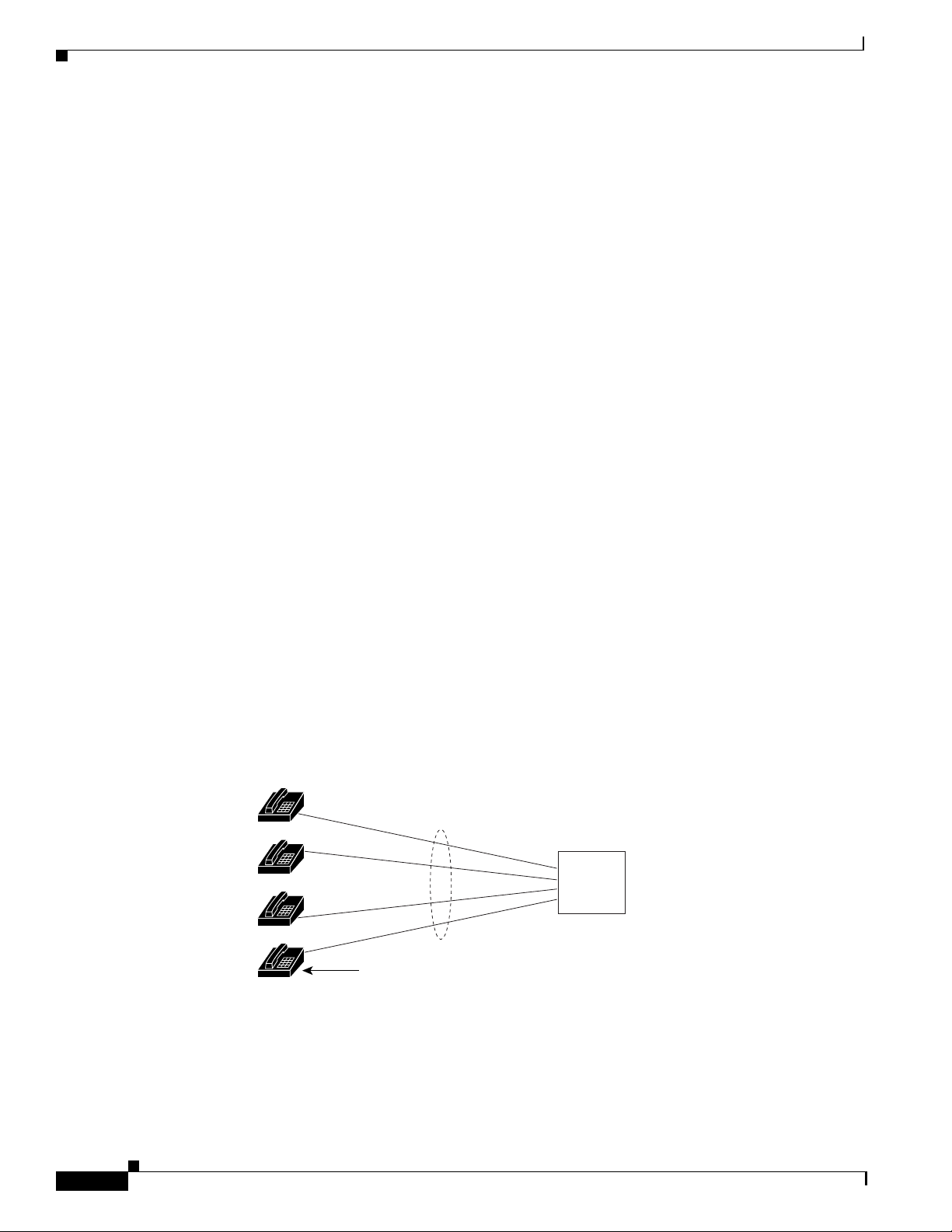
Traditional hoot and holler networks (Figure 1) are analog, multipoint, 4-wire, audio-conference
networks that are always up. When a user wants to communicate, the user pushes a button and speaks
either through a microphone, a hoot phone, a turret, or a squawk box.
Figure 1 Traditional Hoot and Holler Network
emote
cation
emote
cation
emote
cation
emote
cation
Figure 1 illustrates a traditional hoot and holler network. Each remote location is connected to a cen tral
bridge using leased lines. Four-wire connections and N-1 bridges are used to avoid echo problems.
Leased lines
Central site
N-1
voice
bridge
5836
Cisco IOS Release 12.1(5)T
2
Page 3

Cisco Hoot and Holler over IP
Hoot and holler networks are typically spread ov er four to eight sites, although f inancial retail netwo rks
may have hundreds of sites interconnected. W ithin a site, bridging (mix ing voice signals) is done locally
with a standard analog or digital bridge that may be par t of a tradin g turret system. Between sites, there
are two prevalent methods for providing transport:
• Point-to-point leased lines with customer-provided audio bridging at a central site, and
• Carrier-provided audio bridging.
When customers provide their own bridging services with point-to-point leased lines, branch of f i ces in
a metropolitan area commonly have 25 to 50 lines or more.
The second method, carrier-provided audio bridging, is prevalent within the United States but rare for
overseas transport. In this scenario, the audio bridges are located at the carrier's central office and the
4-wire lines are terminated at the client's site on a local audio-bridge equipped with 4-wire plug-ins,
which then feed to local PA system speakers. Customer-provided hoot bridging services can now be
replaced with Cisco Hoot and Holler over IP solutions.
An Overview of Cisco Hoot and Holler over IP
Cisco's VoIP technology, which was initially focused on traditional PBX toll-bypass applications, can
be used to combine hoot and holler net works with data networks. While some customers may ha ve done
some level of hoot and data integration in the late 1980s with time-division multiplexing (TDM), this
form of integration does not allow for dynamic sharing of bandwidth that is characteristic of VoIP. This
dynamic sharing of bandwidth is even more compelling with hoot and holler than with a toll-bypass
application, because some hoot circuits may be active for an hour or two for morn ing reports but might
be dead for the rest of the day—the idle bandwidth can be used by the data applications during these
long periods of inactivity.
Feature Overview
Beginning with the Cisco IOS Release 12.1(2)XH, Cisco Hoot and Holler over IP can be implemented
using Cisco's VoIP technology . This solution le v erages Ci sco's IOS ex pertise in VoIP, quality of service
(QoS), and IP multicasting (IPmc) and is initially a v ailable on Cisco 26 00 and 3600 series mu ltiservice
routers.
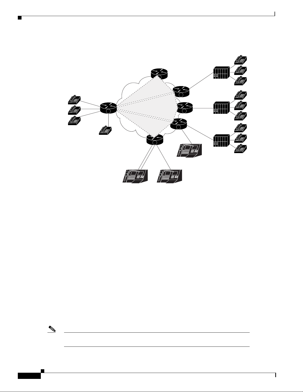
Figure 2 shows a diagram of the Cisco Hoot and Holler over IP solution connecting legacy hoot
equipment over an IP network.
Note The "V" on the Cisco router icons signifies that some of the hoot and holler bridging
function is being done by the router's digital signal processors (DSPs).
Cisco IOS Release 12.1(5)T
3
Page 4
Feature Overview
35839
E
E&M = ear and mouth
Cisco Hoot and Holler over IP
Figure 2 Hoot and Holler over IP using Cisco 2600 and Cisco 3600 Series Routers
PBX
&M phones
V
FXS
V
Multicast group 1
Multicast group 3
Multicast group 2
T1/E1
V
T1/E1
Turret Turret
FXO
V
FXO
V
V
FXO
Turret
PBX
PBX
Four-wire E&M, E1/T1, FXO, and FXS configurations provide continuous VoIP connections across a
packet network. By using the inherent point-to-multipoint characteristic of IPmc, the routers can take
several inbound voice streams from the traditional hoot de vices, and forward the pack etized voice over
the IP network to all parties within a defined hoot and holler group.
Voice Multicasting
The voice multicasting feature on Cisco 2600 and Cisco 3600 series routers uses Cisco Voice over IP
(VoIP) technology to create a point-to-multipoint hoot and holler network over an IP connection.
Voice multicasting telephones can be connected to routers in the following ways:
• Connect a 4-wire E&M telephone, which has no dial and is always off-hook, directly to an E&M
voice interface card that is installed in a voice network module. Configure the E&M interface for
four-wire trunk operation. For information about configuring E&M interfaces, see the
Cisco IOS Multiservice Applications Configuration Guide , Release 12.1.
Note The voice multicasting feature supports only one E1/T1 line per high-density voice
Cisco IOS Release 12.1(5)T
4
• Connect a conventional telephone to a PBX that is connected to an E&M voice interface card.
• Connect a conv entional telephone to an FXS voice interf ace card that is installed in a voice network
module.
• Connect a conventional telephone to a PBX that is connected through a E1/T1 line to a multiflex
trunk interface card that is installed in a high-density voice network module.
network module.
Page 5
Cisco Hoot and Holler over IP
viewer
IP/TV Access
Feature Overview
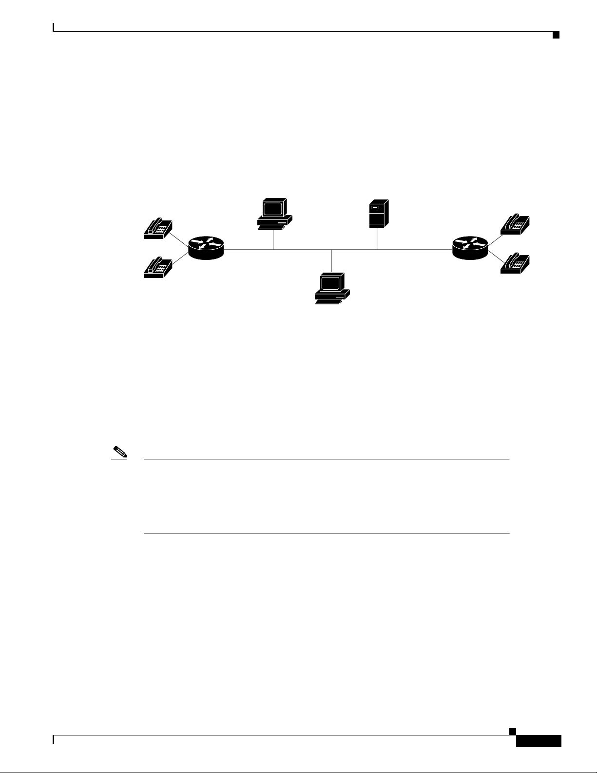
The Cisco Hoot and Holler over IP feature enables you to access ongoi ng IP/TV multicasts for listening
to voice content of the IP/TV session. For complete information on IP/TV, see the IP/TV Content
Manager Installation and User Guide .
Figure 3 Cisco Hoot and Holler over IP Access to IP/TV Multicast
IP/TV
Content Manager
IP/TV
IP/TV
server
35970
For the Cisco Hoot and Holler over IP and IP/TV interaction to work correctly:
• Ensure that you have a properly connected and configured network for Voice over IP with the
Cisco Hoot and Holler over IP feature enabled, using the session protocol multicast command.
• Ensure that the server configured with the IP/TV Content Manager is in the same Ethernet network
as the Cisco Hoot and Holler over IP functionality.
• Ensure that the Cisco Hoot and Holler over IP multicast details are registered with the IP/TV
Content Manager.
Note IP/TV support for Cisco Hoot and Holler over IP uses only G.711 u-law (mu-law)
Content Manager
encoding.
IP/TV supports one audio stream for Cisco Hoot and Holler over IP.
IP/TV does not support arbitration and mixing.
On the configuration screen (Administration Tool>Scheduled Programs>New
Program>Configuration), provide the following details:
• Multicast address
• RTP port—defined by the dial-peer in the router
• IP/TV server—IP address or name
• From the Settings>Content Manager option:
–
Click Add New.
–
Enter the IP/TV server name.
Cisco IOS Release 12.1(5)T
5
Page 6

Feature Overview
–
The port number must be 80, because it is HTTP.
–
Click OK and exit.
Note In the Content Manager, be sure to specify the multicast IP address and RTP po rt for the
Cisco Hoot and Holler over IP session.
Interactive Voice Response (IVR)
The Cisco Hoot and Holler over IP feature can support Interactiv e Voice Response (IVR) as a means of
authentication, authorization, and accounting (AAA) control . See the section “Configuring Interactive
Voice Response (IVR) ” in the Multiservice Applications Configuration Guide and the command
descriptions in the Multiservice Applications Command Reference for more information.
Migration Strategy
To aid troubleshooting and allow for regionalized hoot and holler conferences, most hoot and holler
networks today are structured by interconnecting multiple, regional hoot networks with a centralized
bridge. The regional hoot networks are built using either carrier-based multidrop circuits or point-topoint circuits bridged by the customer. All of these circuits are connected through patch panels that
allow for these regional bridges to be connected for a larger corporate-wide conference call. This is
typically done for the "morning call" that is broadcast to all locations, advising of market movements,
recommendations, and commentary. Later in the day, the patch panel may be reconfigured to allow for
local or regional conference bridges. This allows for multiple conference calls for various purposes,
without provisioning multiple ci rcuits. By se gmenting the n etwork in to regi ons, troubl eshooting is also
easier because any audio disturbance, feedback, or level problems can be isolated to a smaller subset of
remote offices for more specific troubleshooting.
The highly segmented nature of existing hoot and holler networks can be leveraged in the migration
from legacy hoot technology to Cisco Hoot and Holler over IP. A small segment of the hoot network
can be converted to Cisco Hoot and Holler over IP while preserving the operational procedures at the
main office.
Note that the migration to Cisco Hoot and Holler o ver I P does not require replacing end-user equipment
or central bridging equipment. The main impetus for this first phase of migration is to eliminate the
recurring expense of carrier multidrop circuits or dedicated leased lines. By minimizing changes
presented to the end user while realizing an attractive payback period on the capital costs, migration
success is maximized.
Cisco Hoot and Holler over IP
As the entire hoot network con v erg es with the data network , additional functionality can be intr oduced.
Since the hoot and holler connections are no w carried in standard multicast RTP packets, hoot channels
can now be received by a soft client such as IP/TV, which can receive an IP multicast RTP stream. An
alternate migration strategy is to use Cisco Hoot and Holler over IP technology initially as a backup for
the existing hoot circuits within a region with a phased plan of cutting over to Cisco Hoot and Holler
over IP as the primary t ransport while keeping the e xisting circuits as a backup for a predefined bu rn-in
period.
Cisco IOS Release 12.1(5)T
6
Page 7

Cisco Hoot and Holler over IP
Technical Details of the Cisco Hoot and Holler over IP Solution
This section describes how Cisco Hoot and Holler ov er IP wo rks from a technical perspecti ve. It co vers
design considerations in terms of IOS configurations and DSP mixing functionality as well as
bandwidth planning and QoS, w ith the fol lowing assumptions:
1. That you have some level of Cisco IOS experience.
2. That you ha ve some e xperience conf iguring QoS features with Cisco IOS. If not, please refer to the
IOS documentation on CCO at:
http://www.cisco.com/univercd/cc/td/doc/product/software/ios121/121cgcr/ip_c/index.htm
3. That you have some experience configuring VoIP with Cisco IOS. If not, please refer to the IOS
documentation on CCO at:
http://www.cisco.com/univercd/cc/td/doc/product/software/ios121/121cgcr/multi_c/ mcpr t1/mc dv
oip.htm
4. That you have some experience configuring IP multicasting with Cisco IOS. If not, please refer to
the documentation on CCO at:
http://www.cisco.com/univercd/cc/td/doc/product/software/ios121/121cgcr/ip_c/ipcprt3/1cdmulti.
htm
5. That you have a working IP network, with IP multicasting configured using the Cisco 2600 and
Cisco 3600 series routers. If not, please refer to the documentation on CCO at:
http://www.cisco.com/univercd/cc/td/doc/product/software/ios121/121cgcr/index.htm
Feature Overview
http://www.cisco.com/univercd/cc/td/doc/product/access/acs_mod/cis2600/index.htm
http://www.cisco.com/univercd/cc/td/doc/product/access/acs_mod/cis3600/index.htm
6. That you are familiar with Cisco IP/TV. If not, please refer to the documentation on CCO at:
http://www.cisco.com/univercd/cc/td/doc/product/software/iptv30/
7. That you understand basic hoot and holler concepts and equipment.
IP Multicast and DSP Arbitration and Mixing
When deploying Cisco Hoot and Holler over IP, first consider how the voice streams are going to be
mixing and distributed to other locations. This is done using a combination of two technologies:
• IP multicast (IPmc)
• DSP arbitration and mixing
Since hoot and holler is generally used to allow many people to simultaneously talk and listen to other
people within a hoot group, by definitio n it requires that the same speech be delivered to multiple parties
at the same time. In an IP network, this functionality uses IP multicast ing (IPmc). IPmc all o ws a source
to send a single packet into the IP netw ork and ha ve it duplicated and sent t o many listeners b y the other
routers within the network. This technique is beneficial in that it does not require the source to know
how many listeners there are, as well as not requiring additional processing burden on the source by
having to send a copy of each packet to all listeners. IPmc also allows for listeners to dynamically join
IPmc groups, which eliminates the administrative burden of adding new users every time a new IPmc
session is initiated.
Now that we have established that an IP network can forward packets in a way similar to existing hoot
and holler networks, we also must examine how the individual router/gateways can handle mixing and
arbitrating the various vo ice streams that could initiate or terminate on its voice po rts. This functionality
Cisco IOS Release 12.1(5)T
7
Page 8

Feature Overview
Note The mixing functionality does not do a summation of the voice streams.
Cisco Hoot and Holler over IP
is handled by the onboard DSPs on each voice-card (NM-1V, NM-2V or NM-HDV). Arbitration
invo lves identifying the various sources of the voice stream, and mixing involves taking some of those
voice streams and combining them into a single-sourced voice stream. Cisco Hoot and Holler over IP
can handle many inbound voice streams, but it only arbitrates and mixes three streams to be heard
within the Hoot group. This value works fine in most applications, because beyond three streams two
things happen in normal human conversation:
1. People are not able to distinguish the content of more than three streams.
2. People normally stop speaking if they hear others talking ahead of them.
As previously mentioned, the DSPs in Cisco Hoot and Holler ov er IP do mixing for up to three streams.
This fact is important when netw ork administrat ors consider ho w mu ch bandwidth the y should plan for
in their Cisco Hoot and Holler over IP network. This is especially crucial when planning WAN
bandwidth, which is often much more expensive and much less available than LAN bandwidth.
The advantage to this functionality is that a network administrator never has to be concerned about
provisioning voice bandwidth for more than three times per call bandwidth for each WAN site, which
helps to simplify overall network planning.
Bandwidth Planning
Four main factors must be considered with regard to bandwidth planning for
Cisco H oot and Holler over IP:
1. Codecs used for VoIP (G.711, G.726, G.729 and G.729a are currently supported).
2. Bandwidth management techniques.
3. The number of voice streams to be mixed.
4. The amount of guaranteed bandwidth available on the IP network. This includes both LAN and
Codecs
By default, Cisco IOS sends all VoIP traffic (media, using RTP) at a rate of 50 packets per second. The
packets include not only the voice sample, but also an IP, UDP, and RTP header. The IP/UDP/RTP
header adds an additional 40 bytes to each packet. The amount of bandwidth each VoIP call c onsumes
depends on the codec selected. The resulting bandwidths can be:
• G.729 or G.729a = 3000bytes * 8 bits = 24Kb/call
• G.726 = 6000bytes * 8 bits = 48Kb/call
• G.711 = 10000bytes * 8 bits = 80Kb/call
In addition to these calculations, network administrators must consider the Layer 2 headers
(Frame Relay, PPP, Ethernet, and so on.) and add the a ppropriate number of bytes to ea ch packet.
The following table, Table 1, assumes a payload size (bytes) of 20 ms samples per packet with
50 packets per second.
The value of n is equal to the number of voice streams in a session.
WAN bandwidth, and should take into consideration things such as Frame Relay CIR.
Cisco IOS Release 12.1(5)T
8
Page 9

Cisco Hoot and Holler over IP
The uncompressed bandwidth includes IP/UDP/RTP headers (40 bytes) in the bandwidth calculation.
Compressed RTP (cRTP) reduces the IP/UDP/RTP headers to between 2 to 4 bytes per packet. The
calculation of compressed bandwidth below uses 4 bytes for a compressed IP/UDP/RTP header per
packet.
Maximum RTCP bandwidth is five percent of the total RTP traffic in a hoot and holler session. Since
the Cisco Hoot and Holler over IP application supports mixing of a maximum of three voice streams,
the RTCP bandwidth is limited to five percent of three-voice-stream traffic.
In addition to the above, Layer 2 he aders (Fra me Relay, PPP , Ethernet, and so on) shou ld be considered
and added to the bandwidth calculation.
Table 1 Bandwidth Consideration Table
Codec
g.729
g.726
g.711
Payload Size
(byte)
20 24 9.6 3.6 27.6 13.2
80 48 33.6 7.2 55.2 40.8
160 80 65.6 12.0 92.0 77.6
Bandwidth/ Voice Stream
(Kbps)
Uncompressed Compressed =(1)*n+(3) =(2)*n+(3)
RTCP Bandwidth per
Cisco Hoot and Holler over IP
Session (Kbps)
Feature Overview
Example—One Voice Stream in a
Session (Bandwidth in Kbps)
cRTP, Variable-Payload Sizes and VAD
Some network administrators may consider this amount of bandwidth per call unacceptable or outside
the limits for which they can provide bandwidth, especially in the WAN. There are several options that
network administrators have for modifying the bandwidth consumed per call:
1. RTP header compression (cRTP)
2. Adjustable byte-size of the voice payload
3. Voice activity detection (VAD)
IP/UDP/RTP headers add an additional 40 bytes to each packet, but each packet header is basically
unchanged throughout the call. cRTP can be enabled for the VoIP calls, which reduces the IP/UDP/RTP
headers to between 2 to 4 bytes per packet.
More detailed documentation on cRTP can be found on CCO at:
http://www.cisco.com/univercd/cc/td/doc/product/software/ios121/121cgcr/qos_c/qcprt6/qcdcrtp.htm
In addition to reducing the IP/UDP/RTP headers per packet, the network administrator also has the
option of controlling how much voice payload is included in each packet. This is done using the bytes
keyword and argument in a VoIP dial-peer. The following example shows a dial-peer configuration:
dial-peer voice 1 voip
destination-pattern 4085551234
codec g729r8 bytes 40
session protocol multicast
session target ipv4:239.10.108.252:20102
As the number of bytes per packet is modified, so too is the number of packets per second that are sent.
Voice activity detection (VAD) enables the DS Ps to dynamically sense when there are pauses in a
conversation. When these pauses occur, no VoIP packets are sent into the network. This significantly
reduces the amount of bandwidth used per VoIP call, sometimes as much as 40 to 50 percent. When
voice is present, then VoIP packets are again sent. When using Cisco Hoot and Holler over IP, V AD must
be enabled to reduce the amount of processing of idle packets by the DSPs. In basic VoIP, VAD can be
Cisco IOS Release 12.1(5)T
9
Page 10

Feature Overview
enabled or disabled, but since the DSPs also have to do arbitration and mixing, VAD must be disabled
to reduce the DSPs processing load. In addition to enabling VAD (which is on by default), network
administrators should modify the VAD parameters that sense background noise so that idle noise does
not consume bandwidth.
This can be configured as in the following E&M port example:
voice class permanent 1
signal timing oos timeout disabled
signal keepalive 65535
!
voice-port 1/0/0
voice-class permanent 1
connection trunk 111
music-threshold -30
operation 4-wire
The configuration above is used for a voice-port that is in send/receive mode, and only noise above
-30Db is considered voice.
Virtual Interface (Vif)
Cisco Hoot and Holler over IP
Connection Trunk
In all Cisco Hoot and Holler over IP implementations, the routers are configured with an "interface
vif1." This is a virtual interface that is s imilar to a loopbac k interface—a logical IP interface that is
always up when the router is activ e. In addition, it must be conf igured so the Cisco Hoot and Holler o ver
IP packets that are locally mixed on the DSPs can be fast-switched along with the other data packets.
This interface must reside on its own unique subnet, and that subnet should be included in the routing
protocol updates (RIP, OSPF, and so on).
Cisco Hoot and Holler over IP pro vides an "always-on" commun ications bridge—end users do not need
to dial any phone numbers to reach the other members of a hoot group. To simulate this functionality,
Cisco IOS provides a feature called "connection trunk." Connection trunk provides a permanent voice
call, without requiring any input from the end user, because all of the digits are internally dialed by the
router/gateway.
With traditional VoIP usages of connection trunk, the call is mapped to a remote router/gate way, and all
the H.323 signaling is handled dynamically when the trunk is established. With
Cisco Hoot and Holler over IP, the connection trunk is established to the IP address of the IP multicast
(IPmc) group that maps to the hoot group.
In addition, all negotiation of UDP ports for the audio stream is manually configured. The following
example shows an E&M voice port connection trunk set up for Cisco Hoot and Holler over IP:
voice-port 1/0/0
connection trunk 111
music-threshold -30
operation 4-wire
!
dial-peer voice 1 voip
destination-pattern 111
voice-class permanent 1
session protocol multicast
session target ipv4:237.111.0.0:22222
ip precedence 5
10
Cisco IOS Release 12.1(5)T
Page 11

Cisco Hoot and Holler over IP
Benefits
Feature Overview
In this example, the digits in the connection trunk 111 string match the destination pattern of t he VoIP
dial peer. Also, the session protocol is set to multicast and the session target is pointing to the IPmc
group number with the UDP port (22222) predefined.
Cisco Hoot and Holler over IP provides the following benefits:
• Eliminates yearly reoccurring circuit-switched telecom charges (toll-bypass).
• Eliminates the need for leased-lines and the accompanying charges.
• Reduces the need for Hoot and Holler bridges.
• Improves Hoot and Holler network manageability.
• Reduces the time to troubleshoot a problem from hours to minutes.
• Reduces the time to provision bandwidth from days to a few hours.
• Increases productivity through future applications (such as IP/TV and turret support).
• Ability to integrate voice, video, and data signaling capabilities.
Related Documents
For information about installing voice network modules and voice interface cards in Cisco 2600 and
Cisco 3600 series routers, see the following publications:
• Cisco Network Module Hardware Installation Guide
• WAN Interface Card Hardware Installation Guide
For information about configuring Voice over IP features, see the following publications:
• Software Configuration Guide for Cisco 3600 Series and Cisco 2600 Series Routers
• Voice over IP Quick Start Guide
• Cisco IOS Multiservice Applications Configuration Guide , Release 12.1
For further information about IP multicasting, go to this site:
• IP Multicast Site (http://www.cisco.com/ipmulticast)
For further information about IP/TV, see the following publication:
• IP/TV Content Manager User Guide
For further information about interactive voice response (IVR), see the following document:
• Configuring Interactive Voice Response for Cisco Access Platforms
Restrictions
• Cisco Hoot and Holler over IP supports the mixing of only three voice streams.
• IP/TV does not support the mixing of audio streams.
• IP/TV supports only G.711 u-law (mu-law).
• Voice Interface Card Basic Rate In terface (VIC-BRI) is not supported.
Cisco IOS Release 12.1(5)T
11
Page 12

Supported Platforms
Supported Platforms
Router Platforms:
• Cisco 2600
• Cisco 3 600 serie s
Network Modules:
• NM-HDV
• NM-1V
• NM-2V
Supported Standards, MIBs, and RFCs
Standards
No new or modified standards are supported by this feature.
Cisco Hoot and Holler over IP
MIBs
No new or modified MIBs are supported by this feature.
To obtain lists of MIBs supported by platform and Cisco IOS release and to download MIB modules,
go to the Cisco MIB web site on Cisco Connection Online (CCO) at
http://www.cisco.com/public/sw-center/netmgmt/cmtk/mibs.shtml.
RFCs
No new or modified RFCs are supported by this feature.
Configuration Tasks
See the following sections for configuring Cisco Hoot and Holler over IP:
• Configuring Multicast Routing (Required)
• Configuring the Virtual Interface (Required)
• Configuring VoIP Dial Peers (Required)
• Configuring E&M Voice Ports (Required, if used)
• Configuring for Receive Only Mode (Optional)
• Configuring Relevant Interface (Serial/Ethernet) (Required)
• Configuring Voice Ports in High-Density Voice Network Modules (Required, if using T1/E1)
12
Cisco IOS Release 12.1(5)T
Page 13

Cisco Hoot and Holler over IP
Configuring Multicast Routing (Required)
To enable multicast routing on the platform, perform the following steps:
Command Purpose
Step 1
Router(config)# ip multicast-routing
Configuring the Virtual Interface (Required)
To configure the virtual interface for multicast fast switching, perform the following steps:
Command Purpose
Step 1
Step 2
Step 3
Router(config)# interface vif1
Router(config-if)# ip address address subnet-mask
Router(config-if)# ip pim { sparse mode | dense-mode |
sparse-dense-mode }
Configuration Tasks
Enables multicast routing.
Defines a virtual interface for multicast fast
switching. Routers joining the same session must
have their virtual interfaces on different subnets.
Otherwise, packets are not switched to the IP
network.
Assigns the IP address and subnet mask for the
virtual interface.
Specifies Protocol Independent Multicast (PIM).
Whatever mode you choose should match all the
interfaces in all the routers of your network.
Configuring VoIP Dial Peers (Required)
To configure the VoIP dial peers on the router, perform the following steps:
Command Purpose
Step 1
Step 2
Step 3
Step 4
Router(config)# dial-peer voice tag voip
Router(config-dial-peer)# destination-pattern
multicast-session-number
Router(config-dial-peer)# session protocol multicast
Router(config-dial-peer)# session target
ipv4:address:port
Assigns a variable number (tag) to the VoIP dial
peer.
The destination pattern for the VoIP dial peer must
match the value of the multicast-session-number
string for the corresponding voice port.
This step is mandatory for voice multicasting and
is the command introduced specifically for the
Cisco Hoot and Holler over IP application.
Assigns the session target for voice multicasting
dial peers. This is a multicast address in the range
224.0.1.0 to 239.255.255.255 and must be the
same for all ports in a session.
The audio R TP port is an e ven number in the range
16384 to 32767, and must also be the same for all
ports in a session. An odd-numbered port
(UDP port number + 1) is used for the RTCP
traffic for that session.
Cisco IOS Release 12.1(5)T
13
Page 14

Configuration Tasks
Command Purpose
Step 5
Step 6
Router(config-dial-peer)# ip precedence number
Router(config-dial-peer)# codec (codec-type}
Cisco Hoot and Holler over IP
(Optional) Specifies the IP precedence.
Configures the codec. You must configure the
same codec on all dial peers in a session.
When the default codec, g729r8, is used, it does
not appear in the configuration when the show
running command is used.
14
Cisco IOS Release 12.1(5)T
Page 15

Cisco Hoot and Holler over IP
Configuring E&M Voice Ports (Required, if used)
If using E&M voice ports, configure them by performing the following steps:
Command Purpose
Step 1
Step 2
Step 3
Step 4
Step 5
Step 6
Step 7
Step 8
Step 9
Step 10
Router(config)# voice class permanent tag1
Router(config-class)# signal timing oos timeout
disabled
Router(config-class)# signal keepalive number
Router(config-class)# exit
Router(config)# voice-port
router-slot/voice-slot/VIC-port
Router(config-voice-port)# voice-class permanent tag1
Router(config-voice-port)# connection trunk
multicast-session-number
Router(config-voice-port)# music-threshold threshold
Router(config-voice-port)# operation 4-wire
Router(config-voice-port)# type { 1 | 2 | 3 | 5 }
Defines voice class for transmit-receive mode.
Disables signaling loss detection.
Specifies keepalive signaling packet interval.
Returns to global configuration mode.
Selects the voice port to configure.
Uses voice class tag1 for the port that is al lowed to
speak.
Ties the voice port to a multicast-session number.
(Optional) Sets the music threshold to make VAD
less sensitive.
Specifies 4-wire operation. (2-wire is the default.)
Selects the appropriate E&M interface type
(depending on the end connection—such as PBX):
Configuration Tasks
• Type 1 indicates the following lead
configuration (default—this is the
recommended option):
–
E—Output, relay to ground
–
M—Input, referenced to ground
• Type 2 indicates the following lead
configuration:
–
E—Output, relay to SG
–
M—Input, referenced to ground
–
SB—Feed for M, connected to -48V
–
SG—Return for E, galvanically isolated
from ground
• Type 3 indicates the following lead
configuration:
–
E—Output, relay to ground
–
M—Input, referenced to ground
–
SB—Connected to -48V
–
SG—Connected to ground
• Type 5 indicates the following lead
configuration:
–
E—Output, relay to ground
–
M—Input, referenced to -48V
Cisco IOS Release 12.1(5)T
15
Page 16

Configuration Tasks
Command Purpose
Step 11
Step 12
Step 13
Step 14
Step 15
Step 16
Router(config-voice-port)# signal { wink-start |
immediate | delay-dial }
Router(config-voice-port)# voice-port
router-slot/voice-slot/VIC-port
Router(config-voice-port)# voice-class permanent tag2
Router(config-voice-port)# connection trunk
multicast-session-number
Router(config-voice-port)# music-threshold threshold
Router(config-voice-port)# operation 4-wire
Cisco Hoot and Holler over IP
Configures the signaling type for E&M voice
ports. The default is wink-start. Select
immediate for the Cisco Hoot and Holler over IP
application. In the immediate-start protocol, the
originating side does not wait for a wink before
sending addressing information. After receiving
addressing digits, the terminating side then goes
off-hook for the duration of the call. The
originating endpoint maintains off-hook for the
duration of the call.
Selects another voice port.
Uses voice class tag2 for the receive-only port.
Ties the voice port to the same multicast-session
number as in Step 12.
(Optional) Sets the music threshold to make VAD
less sensitive.
Specifies 4-wire operation. (2-wire is the default.)
Configuring for Receive Only Mode (Optional)
To configure Cisco Hoot and Holler over IP as receive-only mode, perform the following steps:
Command Purpose
Step 1
Step 2
Step 3
Router(config-class)# voice class permanent tag2
Router(config-class)# signal pattern oos receive 0000
Router(config-class)# signal timing oos suppress-all
seconds
Defines voice class for receive-only mode.
Specifies the received signal pattern.
If the transmit out-of-service pattern (from the
PBX to the network) matches for the time
specified, the router stops sending packets to the
network.
Step 4
Router(config-class)# signal keepalive number
Specifies keepalive signaling packet interval.
Configuring Relevant Interface (Serial/Ethernet) (Required)
To configure either the serial or Ethernet interface, perform the following steps:
Command Purpose
Step 1
Step 2
Router(config)# interface { ethernet | serial }
slot/port
Router(config-if)# ip address address subnet-mask
Configures the physical interface (serial/Ethernet )
for transmitting multicast packets.
Assigns the IP address and subnet mask for the
interface.
16
Cisco IOS Release 12.1(5)T
Page 17

Cisco Hoot and Holler over IP
Configuration Examples
Command Purpose
Step 3
Router(config-if)# ip pim { sparse mode | dense-mode |
sparse-dense-mode }
Specifies Protocol Independent Multicast (PIM).
Whatever mode you choose should match all the
interfaces in all the routers of your network.
Step 4
Router(config-if)# no shutdown
Enables the interface.
Configuring Voice Ports in High-Density Voice Network Modules (Required, if using T1/E1)
A multiflex trunk interface card (NM-HDV) in a high-density voice network module requires special
voice-port configuration when connecting for T1/E1 operation. Perform the following steps:
Command Purpose
Step 1
Step 2
Step 3
Step 4
Step 5
Step 6
Step 7
Step 8
Step 9
Step 10
Step 11
Router(config)# voice class permanent tag1
Router(config-class)# signal timing oos timeout
disabled
Router(config-class)# signal keepalive number
Router(config-class)# exit
Router(config)# voice-card number
Router(config-voicecard)# codec complexity high
Router(config)# controller { t1 | e1 } slot/port
Router(config-controller)# ds0-group ds0-group-number
timeslots timeslot-list type type
Router(config)# voice-port slot/port:ds0-group-number
Router(config-voice-port)# connection trunk
multicast-address
Router(config-voice-port)# voice-class permanent tag2
Defines voice class for transmit-receive mode.
Disables signaling loss detection.
Specifies keepalive signaling packet interval.
Returns to global configuration mode.
Selects the card to configure.
Codec complexity must be high. Voice
multicasting does not support medium complexi ty,
which is the default.
Selects the T1 or E1 controller to configure.
Maps a group of time slots to a DS0 group.
Configures a DS0 group that was created in Step 4.
Ties the connection trunk to a multicast address.
This command is repeated for each DS0 group. All
groups use the same multicast address, if
connecting to the same multic ast session.
Uses voice class tag2 for the receive-only port.
Configuration Examples
This section provides a series of configuration examples to help you become familiar with voice
multicasting. These examples also show how to ensure that each configuration is working properly
before proceeding to the next step.
• Voice Multicasting over an Ethernet LAN, page 18
• Voice Multicasting over a WAN, page 22
• Cisco Hoot and Holler over IP with Ethernet Topology (Two Hoot Groups)
• Cisco Hoot and Holler over IP with Frame-Relay Topology (One Hoot Group)
Cisco IOS Release 12.1(5)T
17
Page 18
Configuration Examples
E&M VIC
Note In all of the following configuration examples, the routers are configured with an
interface vif1 command. This is a virtual interface that is similar to a loopback
interface—it is a logical IP interface that is always up when the router is active. In
addition, it must be configured so that the Cisco Hoot and Holler over IP packets that are
locally mixed on the DSPs can be fast-switched along with the other data packets. This
interface needs to reside on its own unique subnet, and that subnet should be included in
the routing protocol updates (RIP, OSPF, and so on).
Voice Multicasting over an Ethernet LAN
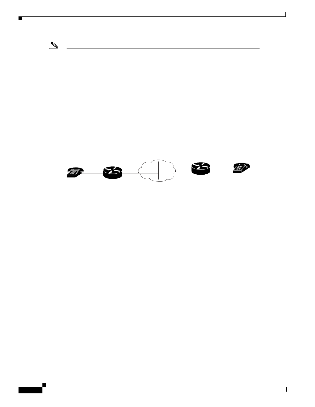
Figure 4 shows the simplest configuration for voice multicasting over an Ethernet LAN. Two routers
are connected to each other over the Ethernet LAN. One E&M phone is connected to each router.
Figure 4 Voice Mult icasting over a LAN
Cisco Hoot and Holler over IP
E&M VIC
2/0/0
IP cloud
3/1/1
Router 2
Router 1
013
In router Abbott (Figure 4), the phone is connected to voice port 2/0/0, using the
router-slot/voice-slot/VIC-port numbering convention. This router is configured as in the following
exampl e :
hostname Abbott
!
ip multicast-routing
!
voice class permanent 1
signal timing oos timeout disabled
signal keepalive 65535
!
interface Vif1
ip address 1.1.1.1 255.0.0.0
ip pim sparse-dense-mode
!
interface Ethernet0/0
ip address 3.3.3.1 255.0.0.0
ip pim sparse-dense-mode
!
ip route 2.0.0.0 255.0.0.0 3.3.3.2
!
voice-port 2/0/0
voice-class permanent 1
connection trunk 111
operation 4-wire
!
dial-peer voice 1 voip
destination-pattern 111
session protocol multicast
session target ipv4:237.111.0.111:22222
!
18
Cisco IOS Release 12.1(5)T
Page 19

Cisco Hoot and Holler over IP
Note The connection-trunk connection type is a point-to-point connection, similar to a tie-line
on a PBX network. All voice traffic—including signaling—placed at one end is
immediately transferred to the other.
Note The E&M voice port must be configured for 4-wire operation.
Configuring the Second Router
In router Costello (Figure 4), the E&M phone is connected to voice port 3/1/1. Router Costello uses the
same configuration as Abbott, except for the following differences:
• The virtual interface must be on a different subnet from the first router.
• The IP address in the Ethernet configuration must be different from that of the first router.
• The voice port and slot should match the router’s hardware configuration.
hostname Costello
!
ip multicast-routing
!
voice class permanent 1
signal timing oos timeout disabled
signal keepalive 65535
!
!
interface Vif1
ip address 2.2.2.2 255.0.0.0
ip pim sparse-dense-mode
!
interface Ethernet0/0
ip address 3.3.3.2 255.0.0.0
ip pim sparse-dense-mode
!
ip route 1.0.0.0 255.0.0.0 3.3.3.1
!
voice-port 3/1/1
voice-class permanent 1
timeouts wait-release 3
connection trunk 222
music-threshold -30
operation 4-wire
!
dial-peer voice 1 voip
destination-pattern 111
session protocol multicast
session target ipv4:237.111.0.111:22222
!
Configuration Examples
Note The multicast session for this port, show n in the session target command, mu st match the
multicast session configured on the first router.
The codec configured for this dial peer must match the codec for the dial peer on the first
router.
Both routers must be configured to use the same connection trun k and destinati on pat tern.
Cisco IOS Release 12.1(5)T
19
Page 20

Configuration Examples
Verifying the Configuration
If you have configured your routers by following these examples, you should now be able to talk over
the telephones. You can also use the show d ial -pe er vo ic e command on each router to verify that the
data you configured is correct.
To verify that an audio path has been established, use the show call active voice command. This
command displays all active voice calls traveling through the router.
High-Density Voice Modules
A multiflex trunk interface card in a high-density voice network module requires special voice-port
configuration. First, select the card to configure:
voice-card 6
codec complexity high
!
Note Codec complexity must be high. Voice multicasting does not support medium complex ity,
which is the default.
Cisco Hoot and Holler over IP
The following commands show how to define the T1 channel and signaling method, and map each DS0
to voice port slot/port:ds0-group:
controller T1 6/0
ds0-group 1 timeslots 1 type e&m-immediate-start
ds0-group 2 timeslots 2 type e&m-immediate-start
ds0-group 3 timeslots 3 type e&m-immediate-start
…
ds0-group 22 timeslots 22 type e&m-immediate-start
ds0-group 23 timeslots 23 type e&m-immediate-start
The following commands show how to configure the voice ports on the multiflex trunk interface card:
!
voice-port 6/0:1
connection trunk 111
!
voice-port 6/0:2
connection trunk 111
!
voice-port 6/0:3
connection trunk 111
…
voice-port 6/0:22
connection trunk 111
!
voice-port 6/0:23
connection trunk 111
Dial Peer Configuration
Cisco IOS software uses objects called dial peers to tie together telephone numbers, voice ports, and
other call parameters. Configuring dial peers is similar to configuring static IP routes—you are
instructing the router what path to follow to route the call.
Cisco IOS Release 12.1(5)T
20
Page 21

Cisco Hoot and Holler over IP
Configuration Examples
Dial peers are identified by numbers, but to avoid confusing these numbers with telephone numbers,
they are usually referred to as tags. Dial peer tags are integers that can range from 1 to 2
(2147483647). Dial peers on the same router must ha ve unique tags, b ut you can reuse the tags on other
routers.
The following commands show how to configure a dial peer with tag 1 for this voice port:
!Configure dial peer.
!Conference 1.
!Phone number 111.
!Multicast address 237.111.0.0, udp port 22222.
dial-peer voice 1 voip
destination-pattern 111
session protocol multicast
session target ipv4:237.111.0.0:22222
ip precedence 5
codec g711ulaw
!
Note The configuration for the codec g711ulaw in the above configuration is not
necessary—the default codec of g729r8 could be used (and it w ould no t di splay fo r show
config).
Tips • The destination-pattern 111 for the VoIP dial peer matches the connection trunk
string for the corresponding voice port.
• The session protocol multicast command is essential for voice multicasting.
• The session target for voice multicasting dial peers is a multicast address in the range 224.0.1.0 to
239.255.255.255. This session target must be the same for all routers in a session. The audio RTP
port is an even number in the range 16384 to 32767, and must also be the same for all routers in a
session. An odd-numbered port (UDP port number + 1) is used for the RTCP traffic for that session.
31
-1
• The following codec restrictions apply:
–
You must configure the same codec on all dial peers and routers in a sess ion.
–
Only G.711, G.726, and G.729 codecs are supported.
–
When the default codec, G.729r8, is used, it does not appear in the configuration.
• Voice activity detection (VAD) is enabled by default. Cisco recommends that this setting should not
be changed.
Ethernet Configuration
Configure the router’s Ethernet interface as follows:
!Configure physical interface for transmitting multicast packets.
!
interface ethernet 0/0
ip address 1.5.13.13 255.255.255.0
ip pim sparse-dense-mode!
Cisco IOS Release 12.1(5)T
21
Page 22

Configuration Examples
Voice Multicasting over a WAN
The configuration for voice multicasting sessions over IP on Frame Relay is the same as for the Ethernet
LAN in the previous example. Configure the WAN interface on each router with the ip address and ip
pim sparse-dense-mode commands as shown in the section, Voice Multicasting over an Ethernet LAN.
Quality of Service
Voice traffic is much more sensitive to timing variat ion s than dat a traffic. For good voice performance,
configure your data network so that v oice packets ar e not lost or del ayed. The follo wing e xample sho ws
one way to improve quality of service (QoS) for voice multicasting over a Frame Relay connection:
!Configure physical interface for transmitting multicast packets.
!Listen to packets of Session Announcement Protocol (SAP).
!This example uses a subinterface
!
interface serial0/0
encapsulation frame-relay
frame-relay traffic-shaping
no frame-relay broadcast-queue
!
interface serial0/0.1 point-to-point
ip address 5.5.5.5 255.255.255.0
ip pim sparse-dense-mode
frame-relay class hootie
frame-relay interface-dlci 100
frame-relay ip rtp header-compression
!
!Frame relay class commands.
!
map-class frame-relay hootie
frame-relay cir 64000
frame-relay bc 2000
frame-relay mincir 64000
no frame-relay adaptive-shaping
frame-relay fair-queue
frame-relay fragment 80
frame-relay ip rtp priority 16384 16383 64
Cisco Hoot and Holler over IP
22
Note In the frame-relay ip rtp priority command, the first number is the audio port. The
second number is the number of consecutive audio ports to which the IP RTP priority
queuing applies. The third number is the bandwidth, which should equal the bandwidth
needed for each call multiplied by the number of calls.
Cisco IOS Release 12.1(5)T
Page 23
Cisco Hoot and Holler over IP
Configuration Examples
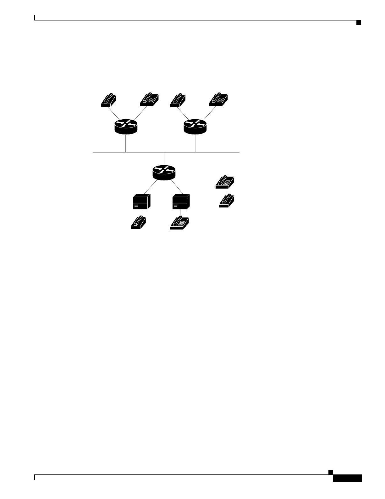
Cisco Hoot and Holler over IP with Ethernet Topology (Two Hoot Groups)
Figure 5 Cisco Hoot and Holler over IP with Ethernet Topology
E&M
4-wire
FXS
E&M = ear and mouth
In this configuration, two hoot and holler groups are set up by defining two multicast groups
(237.111.0.111 and 237.111.0.112) and mapping the connection trunk 111 and connection trunk 112
commands from the voice ports to the VoIP dial peers associated with each group. Each router is
connected to a dedicated switch port, and IP precedence is set to 5 for all Cisco Hoot and Holler over
IP packets.
Router-1 (E&M 4-Wire Ports)
hostname Router-1
!
ip multicast-routing
!
voice class permanent 1
signal timing oos timeout disabled
signal keepalive 65535
!
interface Vif1
ip address 1.1.1.1 255.255.255.0
ip pim sparse-dense-mode
!
!
interface Ethernet0/0
ip address 1.5.13.1 255.255.255.0
ip pim sparse-dense-mode
!
router rip
network 1.1.1.0
network 1.5.13.0
!
voice-port 1/0/0
voice-class permanent 1
connection trunk 111
Router 1
Router 3
FXO FXO
PBX PBX
Router 2
35969
Group 1
Group 2
Cisco IOS Release 12.1(5)T
23
Page 24

Configuration Examples
Cisco Hoot and Holler over IP
music-threshold -30
operation 4-wire
!
voice-port 1/0/1
voice-class permanent 1
connection trunk 112
music-threshold -30
operation 4-wire
!
dial-peer voice 111 voip
destination-pattern 111
session protocol multicast
session target ipv4:237.111.0.111:22222
ip precedence 5
!
dial-peer voice 112 voip
destination-pattern 112
session protocol multicast
session target ipv4:239.194.0.10:22224
ip precedence 5
!
end
Router-2 (FXS Ports)
hostname Router-2
!
ip multicast-routing
!
voice class permanent 1
signal timing oos timeout disabled
signal keepalive 65535
!
interface Vif1
ip address 2.2.2.2 255.255.255.0
ip pim sparse-dense-mode
!
interface Ethernet0/0
ip address 1.5.13.2 255.255.255.0
ip pim sparse-dense-mode
!
router rip
network 2.2.2.0
network 1.5.13.0
!
dial-peer voice 111 voip
destination-pattern 111
session protocol multicast
session target ipv4:237.111.0.111:22222
ip precedence 5
!
dial-peer voice 112 voip
destination-pattern 112
session protocol multicast
session target ipv4:239.194.0.10:22224
ip precedence 5
!
end
24
Note If you want to join the hoot and holler sessio n direc tly with out having to dial any session
numbers, use the command connection plar, followed by the multicast-session number.
Cisco IOS Release 12.1(5)T
Page 25
Cisco Hoot and Holler over IP
Router-3 (FXO Ports)
Configuration Examples
hostname Router-3
!
ip multicast-routing
!
voice class permanent 1
signal timing oos timeout disabled
signal keepalive 65535
!
interface Vif1
ip address 3.3.3.3 255.255.255.0
ip pim sparse-dense-mode
!
interface Ethernet0/0
ip address 1.5.13.3 255.255.255.0
ip pim sparse-dense-mode
!
router rip
network 3.3.3.0
network 1.5.13.0
!
dial-peer voice 111 voip
destination-pattern 111
session protocol multicast
session target ipv4:237.111.0.111:22222
ip precedence 5
!
dial-peer voice 112 voip
destination-pattern 112
session protocol multicast
session target ipv4:239.194.0.10:22224
ip precedence 5
!
end
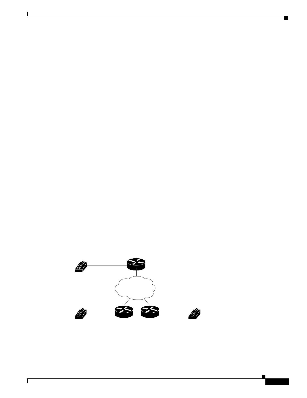
Cisco Hoot and Holler over IP with Frame-Relay Topology (One Hoot Group)
Figure 6 Cisco Hoot and Holler over IP with Frame-Relay Topology
Router 1
IP multicast
network
Router 2
Router 3
In this topology , three rout ers are connected using 64K Frame-Relay PVCs in a hub and spo ke topology,
with Router 1 being the hub. We have defined one hoot and holler group. All three routers have been
configured to traffic-shape their data and voice on the WAN to CIR, and all thre e routers are using IP
RTP priority to guarantee QoS for the Cisco Hoot and Holler over IP packets. In addition, the
frame-relay broadcast-queue is disabl ed on the serial interfaces. This occurs because, by default, the
35838
Cisco IOS Release 12.1(5)T
25
Page 26

Configuration Examples
Router-1
Cisco Hoot and Holler over IP
broadcast-queue is only 40 packets deep and Cisco Hoot and Holler over IP transmits packets at 50
packets per second. Unless the queue is disabled, some packets would be dropped and voi ce QoS would
be degraded.
hostname Router-1
!
ip multicast-routing
!
voice class permanent 1
signal timing oos timeout disabled
signal keepalive 65535
!
interface Vif1
ip address 1.1.1.1 255.255.255.0
ip pim sparse-dense-mode
!
router rip
network 1.1.1.0
network 5.5.5.0
network 5.5.6.0
!
interface Serial0/0
no ip address
ip pim sparse-dense-mode
encapsulation frame-relay
frame-relay traffic-shaping
no frame-relay broadcast-queue
!
interface Serial0/0.1 point-to-point
ip address 5.5.5.1 255.255.255.0
ip pim sparse-dense-mode
frame-relay class hoot-n-holler
frame-relay interface-dlci 100
frame-relay ip rtp header-compression
!
interface Serial0/0.2 point-to-point
ip address 5.5.6.1 255.255.255.0
ip pim sparse-dense-mode
frame-relay class hoot-n-holler
frame-relay interface-dlci 101
frame-relay ip rtp header-compression
!
map-class frame-relay hoot-n-holler
frame-relay cir 128000
frame-relay bc 1280
frame-relay mincir 128000
frame-relay fragment 160
frame-relay ip rtp priority 16384 16384 128
no frame-relay adaptive-shaping
!
voice-port 1/0/0
voice-class permanent 1
connection trunk 111
music-threshold -30
operation 4-wire
!
dial-peer voice 1 voip
destination-pattern 111
session protocol multicast
session target ipv4:237.111.0.0:22222
26
Cisco IOS Release 12.1(5)T
Page 27

Cisco Hoot and Holler over IP
Router-2
Configuration Examples
ip precedence 5
hostname Router-2
!
ip multicast-routing
!
voice class permanent 1
signal timing oos timeout disabled
signal keepalive 65535
!
interface Vif1
ip address 2.2.2.2 255.255.255.0
ip pim sparse-dense-mode
!
router rip
network 2.2.2.0
network 5.5.5.0
!
interface Serial0/0
no ip address
ip pim sparse-dense-mode
encapsulation frame-relay
frame-relay traffic-shaping
no frame-relay broadcast-queue
!
interface Serial0/0.1 point-to-point
ip address 5.5.5.2 255.255.255.0
ip pim sparse-dense-mode
frame-relay class hoot-n-holler
frame-relay interface-dlci 100
frame-relay ip rtp header-compression
!
map-class frame-relay hoot-n-holler
frame-relay cir 128000
frame-relay bc 1280
frame-relay mincir 128000
frame-relay fragment 160
frame-relay ip rtp priority 16384 16383 128
no frame-relay adaptive-shaping
!
voice-port 1/0/0
voice-class permanent 1
connection trunk 111
music-threshold -30
operation 4-wire
!
dial-peer voice 1 voip
destination-pattern 111
session protocol multicast
session target ipv4:237.111.0.0:22222
ip precedence 5
Router-3
hostname Router-3
!
ip multicast-routing
!
voice class permanent 1
signal timing oos timeout disabled
signal keepalive 65535
Cisco IOS Release 12.1(5)T
27
Page 28

Configuration Examples
Cisco Hoot and Holler over IP
!
interface Vif1
ip address 3.3.3.3 255.255.255.0
ip pim sparse-dense-mode
!
router rip
network 3.3.3.0
network 5.5.6.0
!
interface Serial0/0
no ip address
ip pim sparse-dense-mode
encapsulation frame-relay
frame-relay traffic-shaping
no frame-relay broadcast queue
!
interface Serial0/0.1 point-to-point
ip address 5.5.6.2 255.255.255.0
ip pim sparse-dense-mode
frame-relay class hoot-n-holler
frame-relay interface-dlci 101
frame-relay ip rtp header-compression
!
map-class frame-relay hoot-n-holler
frame-relay cir 128000
frame-relay bc 1280
frame-relay mincir 128000
frame-relay fragment 160
frame-relay ip rtp priority 16384 16383 128
no frame-relay adaptive-shaping
!
voice-port 1/0/0
voice-class permanent 1
connection trunk 111
music-threshold -30
operation 4-wire
!
dial-peer voice 1 voip
destination-pattern 111
session protocol multicast
session target ipv4:237.111.0.0:22222
ip precedence 5
28
Cisco IOS Release 12.1(5)T
Page 29

Cisco Hoot and Holler over IP
Command Reference
This section documents a new command. All other comma nds used with this feature are documented in
the Cisco IOS Release 12.1 command reference publications.
• session protocol multicast
Command Reference
Cisco IOS Release 12.1(5)T
29
Page 30

session protocol multicast
session protocol multicast
To set the session protocol as multicast, use the session protocol multicast dial-peer configuration
command. To negate this command and return to the cisco default session protocol, use the no version
of this command.
session protocol multicast
no session protocol multicast
Syntax Description There are no keywords or arguments.
Defaults When this command is not implemented, the default session protocol is cisco.
Command Modes Dial-peer configuration
Cisco Hoot and Holler over IP
Command History
Release Modification
12.1(2)XH This command was introduced on Cisco 2600 and Cisco 3600 series routers
for the Cisco Hoot and Holler over IP application.
Usage Guidelines Use the session protocol multicast dial-peer configuration command for v oice conferencing in a Hoot
and Holler networking implementation. This command allows more than two ports to join the same
session simultaneously. It is supported on Cisco 2600 and Cisco 3600 series routers.
Examples The following example shows the use of the the session protocol multicast dial-peer configuration
command in context with its accompanying commands:
Router(config)# dial-peer voice 111 voip
Router(config-dial-peer)# destination-pattern 111
Router(config-dial-peer)# session protocol multicast
Router(config-dial-peer)# session target ipv4:237.111.0.111:22222
Router(config-dial-peer)# ip precedence 5
Router(config-dial-peer)# codec g711ulaw
Related Commands
Command Description
session target ipv4 Assigns the session target for voice-multicasting dial peers.
30
Cisco IOS Release 12.1(5)T
Page 31

Cisco Hoot and Holler over IP
Glossary
Glossary
CIR—Committed information rate. The average rate of information tran sfer a subscriber (for e xample,
the network administrator) has stipulated for a Frame-Relay PVC.
Codec—Coder-decoder. Device that typically uses pulse-code modulation (PCM) to transform analog
signals into a digital bit stream and digital signals back into analog signals. In Voice over IP, it specifies
the voice-coder rate of speech for a dial peer.
Dial peer—An addressable call endpoint that contains configuration information including voice
protocol, a codec type, and a telephone number associated with the call. There are five kinds of dial
peers: POTS, VoIP, VoFR, VoATM, and VoHDLC. In Voice over IP, there are two kinds of dial peers:
• POTS—Connected throu gh a traditio nal telephon y netw ork and points to a particular v oice port on
a voice network device.
• VoIP—Connected th rough a pac ket network (IP network for VoIP) and points to specific VoIP
device.
DSP—Digital signal processor.
DTMF—Dual tone multifrequency. Uses two simultaneous voice-band tones for dial such as
touch-tone.
E&M—Ear and mouth. Stands for the 2-wire or 4-wire interface with separate signaling paths for the
receiving and transmitting signals—a type of signaling traditionally used in the telecommunications
industry. Indicates the use of a handset that corresponds to the ear (receiving) and mouth (transmitting)
component of a telephone. E&M is a trunking arrangement generally used for two-way switch-to-switch
or switch-to-network connecting. The Cisco analog E&M interface is an RJ-48 connector that allows
connections to PBX trunk lines (tie lines). E&M is also available on E1 and T1 digital interfaces.
FXO—Foreign Exchange Office. An FXO interface connects to the Public Switched Te lephone
Network (PSTN) central office and is the interface offered on a standard telephone. The Cisco FXO
interface is an RJ-11 connector that allows an analog connection at the PSTN's central office or to a
station interface on a PBX.
FXS—Foreign Exchange Station. An FXS interface connects directly to a standard telephone and
supplies ring, voltage, and dial tone. Cisco's FXS interface is an RJ-11 connector that allows
connections to basic telephone service equipment, keysets, and PBXs.
Hoot and holler—A broadcast audio network used extensively by the brokerage industry for market
updates and trading. Similar networks are used in publishing, transportation, power plants, and
manufacturing.
IVR—Interactive v oice response. When someone dials in, IVR respond s with a prompt to get a personal
identification number (PIN), and so on.
PBX—Private branch exchange. Digital or analog telephone switchboard or switching facility located
on the subscriber premises and used to connect private and public telephone networks .
PVC—Permanent virtual circuit.
QoS—Quality of service. QoS refers to the measure of service quality provided to the user.
TDM—Time-division multiplexing.
Trunk—Service that allows quasi-transparent connections between two PBXs, a PBX and a local
extension, or some other combination of telephony interfaces to be permanently conferenced together
by the session application and signaling passed transparently through the IP network.
VAD—Voice activity detection.
VIC—Voice interface card.
Cisco IOS Release 12.1(5)T
31
Page 32

Glossary
Cisco Hoot and Holler over IP
VNM—Voice network module.
VoIP—Voice over Internet Protocol.
32
Cisco IOS Release 12.1(5)T
 Loading...