

Page 1
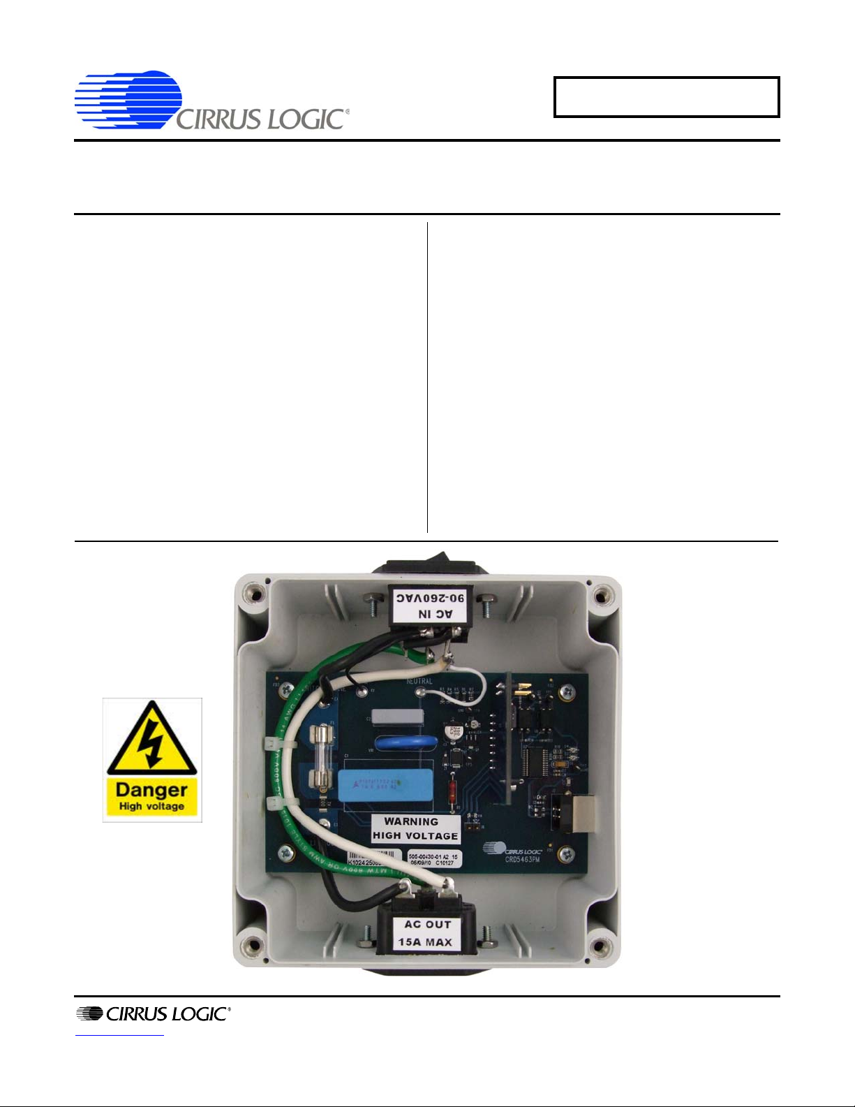
Actual Size:
120mm x 120mm x 60mm
AC Load
AC Line
Input/Switch
USB Port
CRD5463PM
CRD5463PM Power Monitor
Reference Design and Software
Features
Easy Plug-and-play Design
USB Communication with PC
Real-time Measurements:
– Line Voltage
– Load Current
–Active Power
–Reactive Power
– Apparent Power
– Power Factor
– Line Frequency
– Temperature
Operational Voltage: 90 ~ 260 VAC
Maximum Load Current: 15 A RMS
Active Power Measurement Accuracy:
– 0.2%, 3 ~ 3900 W
Lab Windows™/CVI™ GUI Software
Factory Calibrated, Re-calibration Capable
General Description
The CRD5463PM demonstrates the CS5463 power
measurement IC. It has an integrated AC-DC power supply,
voltage and current sensors, and isolated UART/USB
interface. Working with the GUI software, it provides accurate
real-time measurements of line voltage, load current, line
frequency, active power, reactive power, apparent power,
power factor, and temperature.
The CRD5463PM includes two power cords, a USB cable, and
a plug adaptor. When used with a PC, the CRD5463PM
immediately becomes a high-precision power meter. The
UART interface communication protocol, GUI, and MCU
software source codes are also available from Cirrus Logic.
The CRD5463PM is a useful design reference and evaluation
tool for customers to develop power metering/monitoring
systems that use the CS5463 IC.
ORDERING INFORMATION
CRD5463PM Power Monitor Reference Design
www.cirrus.com
Copyright Cirrus Logic, Inc. 2010
(All Rights Reserved)
OCT ‘10
DS805RD2
Page 2
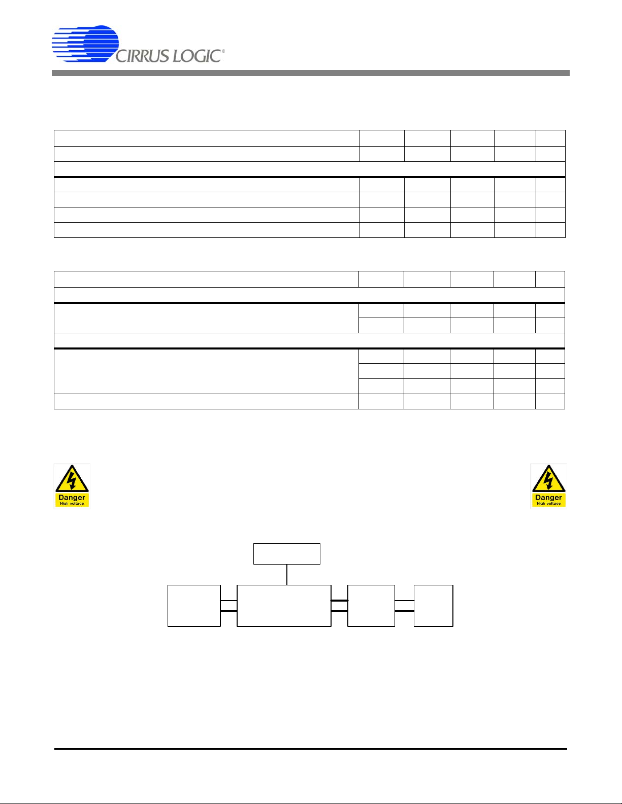
CRD5463PM
CRD5463PM
AC
SOURCE
AC
Load
GUI
USB
Reference
Meter
(V, A)
1. CHARACTERISTICS AND SPECIFICATIONS
1.1 Recommended Operating Conditions
Parameter Symbol Min Typ Max Unit
Voltage Range V
Current Range
RMS Current I
Peak Current I
Frequency Range Freq 5 2000 Hz
Operating Tempereture T
AC
rms
peak
A
1.2 Electrical Characteristics
Parameter Symbol Min Typ Max Unit
Power Consumption (Note 1)
Current Consumption
Power Consumption
Accuracy (Note 2)
RMS Voltage Measurement (90~ 260 VAC)
RMS Current Measurement (30 mA ~ 15 A)
Active Power Measurement (3 W ~ 3900 W)
Measurement Bandwidth BW - - 2 kHz
P
V
I
P
I
AC
AC
accu
accu
accu
90 - 260 V
--15A
--22A
-40 - +85 ºC
-79-mA
-2.3-W
-±0.1-%
-±0.2-%
-±0.2-%
NOTES:
1. Measured at VAC = 240 V and TA= 25º C.
2. Measured at T
= 25º C and PF=1.
A
WARNING
High Voltage Hazard
When the CRD5463PM is connected to AC lines, high voltage is present inside the box.
DO NOT REMOVE THE PROTECTIVE COVER FROM THE CRD5463PM WHEN POWER IS CONNECTED.
Figure 1. Calibration and Test Connection Diagram
NOTES:
1. Voltage drop and power loss in the cable connecting the CRD5463PM and the reference meter may introduce
additional error.
2. The measurement bandwidth of the CS5463 is 2 kHz. At low power factor, the CRD5463PM may measure lower
current and higher power factor than the reference meter if the reference meter has a measurement bandwidth
greater than 2 kHz.
3. When testing at low power factor, the peak load current shall never exceed 22 A.
2 DS805RD2
Page 3
CRD5463PM
Voltage & Current
Sensors
CS5463
Power
Measurement
MCU
UART -
USB
SPI
Reset
Interrup t
UART
V
I
AC/DC
UART
Isolation
U
S
B
R
2
Vout
R
1
Vin
2RRR
VinVout
+
×=
mVrms
RR
R
Vin 176
2
max <
+
×
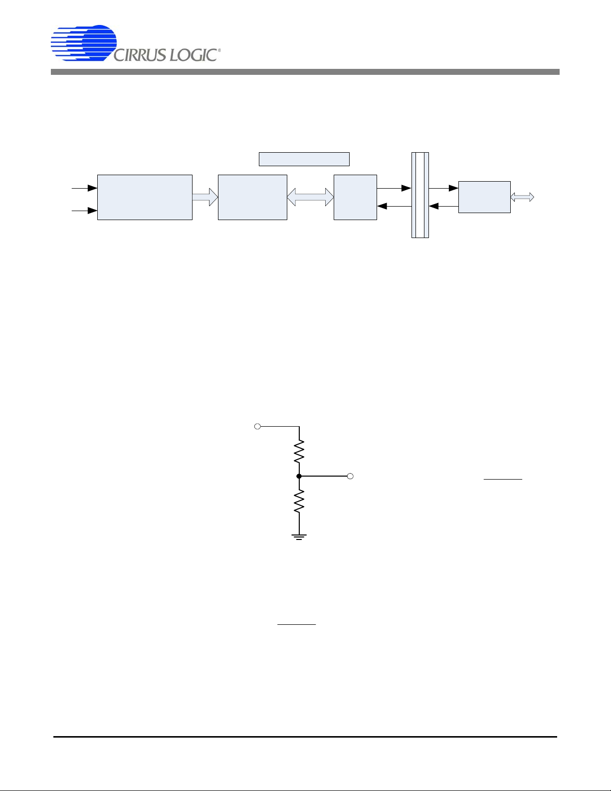
2. SYSTEM OVERVIEW
As illustrated in Figure 1, the CRD5463PM is composed of voltage and current sensors, a CS5463 power
measurement device, an ATtiny2313 microcontroller, opto-coupler isolation, and UART-USB converter.
Figure 2. CRD5463PM Simplified Block Diagram
2.1 DC Power Supplies
There are two isolated +5V DC power domains in the CRD. One is converted from AC power lines through
capacitor-dropper AC/DC power supply and provides +5VDC supply to the CS5463 and MCU. The other
is directly from PC through USB interface and provides +5VDC to the UART-USB converter.
This capacitor type of DC power supply is very low-cost but not efficient. Total power consumption drew
from the AC line is 2.3 Watt and 79mA (tested with 240 VAC input).
2.2 Voltage Sensor
The high AC line voltage must be converted to small voltage signal before being applied onto the CS5463
voltage channel inputs (VIN±). The CRD5463PM uses resistor voltage divider as the voltage sensor.
21
Figure 3. CRD5463PM Resistive Divider Voltage Sensor
The divider ratio is determined by the maximum Vin and the maximum input range of the CS5463 voltage
channel. The maximum input range of the CS5463 voltage channel is 176 mV RMS. The division ratio
shall be chosen to satisfy the equation:
21
To leave some margin, the Vout is normally set around 150 mVrms with the maximum V
CRD5463PM, R2 is 1 kΩ. R1 is composed of four 422 kΩ resistors to increase the total voltage rating of
the voltage sensor.
When V
DS805RD2 3
=260VRMS, V
in
= 260 V × 1 / [1 + (4 × 422)] = 154 mV RMS.
out
. In the
in
Page 4
CRD5463PM
I
R
Shunt
Vout
RshuntIVout
mVpRshuntIpeak 50
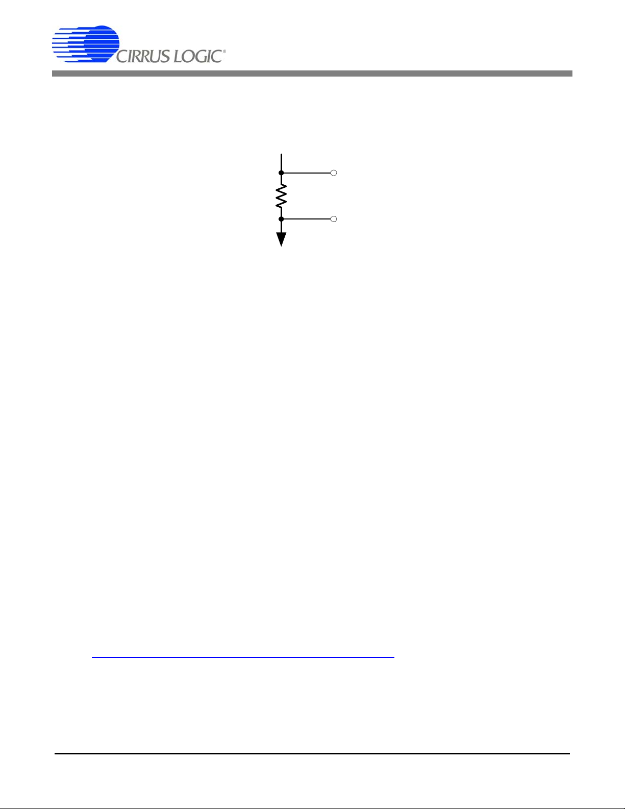
2.3 Current Sensor
The AC load current must be converted into a low-level voltage signal before being applied to the CS5463.
A shunt resistor is a very common choice for current sensing in power monitoring applications because it
is inexpensive, small, linear, and normally doesn't introduce phase shift.
×=
Figure 4. CRD5463PM Shunt Resistor Current Sensor
Benefiting from its 50x gain amplifier and the low noise level on the current channel, the CS5463 can accommodate the ultra low-value shunt to achieve both low power dissipation at high current and high accuracy at low current.
The shunt resistance is determined by the maximum peak load current (I
) and the CS5463 current
peak
channel’s maximum input range. With the 50x PGA setting, the maximum input range of the CS5463’s
current channel is 50 mVp. Therefore, the Rshunt is chosen to satisfy the equation:
<×
The power rating of the shunt should be at least twice the actual power dissipation of the shunt with the
maximum continuous load current.
To measure the maximum of 15 A RMS and 23 A peak load current, the CRD5463PM uses a 2 mΩ, 1.5 W
shunt resistor as the current sensor.
2.4 CS5463 Power Measurement IC
The power measurement device CS5463 is on the daughter board. The CS5463 is an integrated power
measurement device which combines two ΔΣ analog-to-digital converter, power calculation engine and a
serial interface on a single chip. The sensed line voltage and load current are first converted into 24-bit
instantaneous values. The powerful on-chip DSP calculates voltage and current RMS values, active power, reactive power, apparent power, power factor, etc.
All these measurement values are available in specifically addressed 24-bit registers which can be accessed through SPI interface.
For more detailed information of the CS5463, please refer to the CS5463 datasheet.
http://www.cirrus.com/en/pubs/proDatasheet/CS5463_F2.pdf
4 DS805RD2
Page 5
CRD5463PM
2.5 ATtiny2313 Microcontroller
In addition to the CS5463 on the daughter board, an Atmel™ ATtiny2313 microcontroller is used to initialize the CS5463, convert the SPI into UART, and provide nonvolatile memory for the calibrations.
The ATtiny2313 is an MCU with SPI and UART interfaces, 2 kB Flash program memory and 128 bytes
EEPROM data memory. The MCU acts as a communication bridge between the CS5463’s SPI interface
and the UART of the UART-to-USB converter. The EEPROM data memory is used to store calibration
information.
The hardware connections between the ATtiny2313 and the CS5463 are RESET
INT
(interrupt), and connection-configurable clock signals. Through the population of the 0 ohms resistor
R15 or R16, the clock source can be shared between the CS5463 and the ATtimy2313. In the current
version of the CRD5463PM, the CS5463 and ATtiny2313 are configured to use their own clock sources.
The CS5463 uses a 4.096 MHz crystal and the ATtiny2313 uses its internal 8 MHz R-C oscillator.
On the daughter board, connector J4 is provided for programming and debugging the ATtiny2313 MCU.
, SCLK, CS, SDI, SDO,
WARNING
High Voltage Hazard
The signal ground for the daughter board is the power line.
DO NOT CONNECT ANY DEBUGGING OR PROGRAMMING TOOLS TO THE J4 CONNECTOR WHEN
AC LINE POWER IS CONNECTED.
Please consult with Cirrus Logic engineering if re-programming the MCU is desired.
For more detailed information of ATtiny 2313, please refer to the ATtiny2313 datasheet.
2.6 Isolated UART
Because the CRD5463PM uses non-isolated components as the current and voltage sensors, the signal
ground of the CS5463 and MCU is the live connection to the main power. However, the signal ground of
the PC USB port is normally chassis ground or earth ground. The electrical isolation must be fulfilled on
the UART communication interface to allow the CRD5463PM to be connected to a PC through a USB
cable without short-circuit and safety problems. The CRD5463PM uses 2 opto-couplers to isolate the
UART interface. The isolation rating is 5300 V RMS.
2.7 UART-USB Interface- FT232R
A USB-to-UART interface IC, FT232R, is used on the main board to interface the CRD to a PC as a virtual
COM port through the USB connection.
3. SOFTWARE CONTROL
The CRD5463PM comes with GUI software and a USB cable to link the CRD to a PC. The GUI was developed with Lab Windows™/CVI™, a software development package from National Instrumen ts Corporation. The GUI software is available for download on the Cirrus Logic web site at:
http://www.cirrus.com/industrialsoftware
The software was designed to run under Windows 2000™ or Windows XP
DS805RD2 5
®
operating system.
Page 6

CRD5463PM
4. INSTALLATION PROCEDURE
4.1 Software Installation Procedure
FTDI drivers must be installed before the GUI software is launched . Please refer to the following document
for details of how to install the drivers.
4.1.1 GUI Installation
1) Go to Cirrus Industrial Software download website (http://www.cirrus.com/industrialsoftware).
2) Click the link for the GUI desired.
3) Download the file onto the PC and unzip it. A new folder will be created.
4) Open the new folder and run the setup.exe file.
5) Follow the instructions presented by the installation wizard.
6) To Run the GUI, navigate to:
Start > All Programs >Cirrus Power Monitoring Reference (CRD5463PM) > CRD5463PM
4.1.2 Driver Installation
Important: FTDI drivers must be installed before the GUI software is launched . Please r efer to the f ollowing document for details of how to install the drivers.
http://www.ftdichip.com/Documents/AppNotes/AN_104_FTDI_Drivers_Installation_Guide_for_WindowsXP(FT_000093).pdf
4.2 Using the Software
Before launching the software, connect the CRD to an open USB port on the PC using the provided cable.
Connect the CRD to the main power and the load using provided power cord and plug adaptor. Once the
power has been switched on, the software program can be launched.
4.3 Main Window
When the software is launched, the Main window will appear. This window contains information concerning the software's title, revision number, copyright date, etc.
Figure 5. CRD5463PM GUI Main Window
At the top of the screen is a menu bar which displays user options. The menu bar has three items: System,
Connect, and Help.
6 DS805RD2
Page 7

CRD5463PM
4.3.1 Connect Menu
The Connect menu allows user to establish a serial communication connection with CRD5463PM.
Figure 6. CRD5463PM GUI Connect Menu
4.3.2 System Menu
The System menu allows user to operate the power monitoring and re-calibrate the CRD when necessary.
Figure 7. CRD5463PM GUI System Menu
DS805RD2 7
Page 8

CRD5463PM
Quit allows the user to exit the evaluation software. Upon selecting Quit, a message windows appears
and queries if exiting the evaluation software is desired.
Figure 8. CRD5463PM GUI Quit Dialog
4.4 Connect
After Connect to the CRD is selected under this menu, a sub-window will appear.
Figure 9. CRD5463PM GUI Connect to CRD5463PM Window
Follow the instructions on the Connect to CRD5463PM window and the The CRD is connected. message
will pop up if the connection has been established correctly.
Figure 10. CRD5463PM GUI Successful Connection Message
Otherwise a error message will appear, indicating that the initial communication has failed.
Figure 11. CRD5463PM GUI Connection Error Message
Check to verify that the USB cable and power cord are connected properly and the power switch is at th e
ON position.
8 DS805RD2
Page 9
CRD5463PM
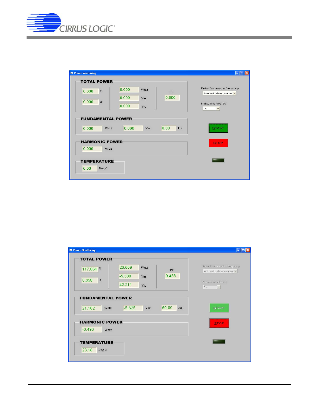
4.5 Power Monitoring Window
After Monitor is selected under the System menu, the Power Monitoring window will appear. The Power
Monitoring window provides the real time measurements.
Figure 12. CRD5463PM GUI Power Monitoring Window
4.5.1 START and STOP Buttons
To start power monitoring, click the green START button in the window. The CRD will start continuous
analog-to-digital conversion, compute the power parameters every N samples, and send calculation results to the GUI. The GUI software receives the data block from the CRD through the connected USB p ort
(virtual COM port), convert the raw register values into true power values based on the calibration information read from the MCU internal EEPROM, and display the final measurement results in the window.
Figure 13. Power Monitoring Window, Results Displayed
DS805RD2 9
Page 10

CRD5463PM
4.5.2 Define Fundamental Frequency
During initialization, the CS5463 is configured to measure the fundamental frequency automatically – the
AFC bit of the Mode register is set by the MCU. The Define Fundamental Frequency selection box enables the user to disable the automatic frequency calculation function and define the specific line frequency by changing the Epsilon register value..
Figure 14. Power Monitoring Window, Define Fundamental Frequecy Menu
4.5.3 Change Measurement Period
The power measurement period or register refreshing rate depends on the CS5463 sample rate and the
configuration of the CS5463 CycleCount (N) register. By default, N is 4000 and the measurement period
is 1 second. The Measurement Period selection box is used to change the CS5463 CycleCount register
value (N) and therefore, change the measurement period.
Cycle Count (N) Measurement Period (Seconds) Refresh Rate (Hz)
8000 2 0.5
4000 1 1
2000 0.5 2
800 0.2 5
400 0.1 10
Figure 15. Power Monitoring Window, Measurement Period Menu
10 DS805RD2
Page 11

CRD5463PM
4.6 Calibration Window
When Calibration is selected from the System menu in the main widow, the Calibration window will appear. The Calibration window is used to re-calibrate the CRD.
Figure 16. System Calibration Window
4.6.1 Calibration Connections
A stable AC source, an accurate reference power meter, and a stable AC load are needed for calibration.
Follow the connection diagram in the System Calibration window to connect the eq uipment and CRD. To
minimize calibration error introduced by the voltage drop on the connection wires, the power cable between the CRD and the reference meter should be as short and as large guage as possible.
4.6.2 Irms Offset Calibration
The CRD5463PM Irms offset calibration is to detect and save the residual value in the Irms register when
the load is zero. This value represents the current channel noise level of the CRD. In normal power monitoring operation, this offset will be removed from the Irms register readings. The GUI also forces all the
power measurements to be zero if the Irms register value is smaller than the offset. Follow the procedure
below to operate the Irms offset calibration.
1) Turn on the power source and adjust the voltage to the nominal operation voltage.
2) Switch on the CRD5463PM.
3) Launch the GUI.
4) Open the System Calibration window
5) Turn off or remove the AC load.
6) Click the Irms Offset CAL button, the GUI will prompt the following message to confirm the load
has been removed from the system.
Figure 17. Calibration Process Confirmation Dialog
DS805RD2 11
Page 12

CRD5463PM
7) Click the Yes button to proceed with the calibration process.
8) Wait for the completion of the process. The Irms Offset calibration takes about 4 seconds.
Figure 18. Calibration Completed Dialog
4.6.3 Gain Calibration
The CRD5463PM gain calibration process is to detect and save the Vrms and Irms register values and
associated true voltage and current values. In normal power monitoring operation, the GUI will use these
values to convert the raw register data into true measurement results. The CRD needs gain calibration
under one voltage and load condition only. Follow the procedure below to operate the gain calibration.
1) Turn on the AC source and adjust the voltage to the nominal operation voltage.
2) Switch on the CRD5463PM.
3) Launch the GUI.
4) Open the System Calibration window.
5) Turn on the load. The power factor of the load should be 1 and the load level should be in the range
of your accuracy interest.
6) Enter the calibration condition, AC volatge and AC current with the voltage and current measurements from the reference meter.
7) Click the GAIN CAL button. The following message will pop up.
Figure 19. Calibration Process Confirmation Dialog
8) Wait for the completion of the process. The gain calibration takes about 5 seconds.
Figure 20. Calibration Completed Dialog
12 DS805RD2
Page 13

5. SCHEMATIC
Figure 21. Schematic (Page 1 of 2)
CRD5463PM
DS805RD2 13
Page 14

CRD5463PM
Figure 22. Schematic (Page 2 of 2)
14 DS805RD2
Page 15

6. BILL OF MATERIALS
&,5586/2*,&
&5'30=B5(9B%
%,//2)0$7(5,$/
,WHP &LUUXV31 5HY 'HVFULSWLRQ 4W\ 5HIHUHQFH'HVLJQDWRU 0)* 0)*31 1RWHV
6WDWXV
1
011-00052-Z1 A CAP 1uF ±20% 440V MTL FLM NPb TH 1 C1 VISHAY BFC233814105
P
2 011-00051-Z1 A CAP 10nF ±20% 440V MTL FLM NPb TH 1 C2 VISHAY BFC233814103
A
3 012-00150-Z1 A CAP 470uF ±20% 16V NPb ELEC CASE F 1 C3 PANASONIC EEE1CA471UP ECO768
A
4 001-02189-Z1 A CAP 0.1uF ±10% 16V X7R NPb 0603 7 C4 C7 C8 C9 C10 C11 C16 KEMET C0603C104K4RAC
A
5 001-01997-Z1 A CAP 0.01uF ±10% 25V X7R NPb 0603 1 C5 KEMET C0603C103K3RAC
A
6 004-00155-Z1 A CAP 4.7uF ±10% 16V TANT NPb CASE A 1 C6 KEMET T491A475K016AS
A
7 001-02068-Z1 A CAP 0.022uF ±10% 50V X7R NPb 0603 2 C12 C13 KEMET C0603C223K5RAC
A
8 001-01622-Z1 A CAP 220pF ±10% 50V X7R NPb 0603 4 C14 C15 C19 C20 KEMET C0603C221K5RAC
A
9 001-02780-Z1 A CAP 22pF ±10% 50V C0G NPb 0805 1 C17 KEMET C0805C220K5GAC
A
10 012-00012-Z1 A CAP 10uF ±20% 16V ELEC NPb CASE A 1 C18 PANASONIC EEE1CS100SR
P
11 070-00173-Z1 A DIODE RECT 1A 400V NPb SMB 1 D1 DIODES INC S1GB-13-F
A
12 070-00055-Z1 A DIODE ARRAY 5V (TVS) ESD NPb SOT143 1 D2 LITTELFUSE SP0503BAHTG
A
13 165-00005-Z1 A LED CLR GRN 2.1V 1mA .16MCD NPb SMD 2 D3 D4 CHICAGO MINIATURE
LAMP
CMD28-21VGC/TR8/T1
A
14 303-00008-Z1 A FUSE CLIP PC MOUNT 5MM NPb 1 F1 KEYSTONE 3517 NEED 2 CLIPS PER FUSE
A
15 115-00010-Z1 A HDR 10x1 ML .1"CTR S NPb GLD 0 J1 SAMTEC TSW-110-07-G-S DO NOT POPULATE
A
16 110-00041-Z1 A CON RA USB BLK NPb TH 1 J2 AMP 292304-1
A
17 115-00310-Z1 A HDR 8x1 ML .1" 093BD RA GLD NPb TH 1 J3 SAMTEC TSW-108-08-G-S-RA
A
18 115-00016-Z1 A HDR 3x2 ML .1"CTR 062 S GLD NPb 1 J4 SAMTEC TSW-103-07-G-D
A
19 020-00673-Z1 A RES 0 OHM 1/10W ±5% NPb 0603 FILM 3 J5 R16 R22 DALE CRCW06030000Z0EA
A
20 115-00014-Z1 A HDR 2x1 ML .1" 062BD ST GLD NPb TH 1 J6 SAMTEC TSW-102-07-G-S
A
21 145-00040-Z1 A FE 1.5A 80 ohm@100MHz NPb 0805 1 L1 LAIRD MI0805K400R-10
A
22 304-00004-Z1 A SPCR STANDOFF 4-40 THR .500"L NPb 0 MH1 MH2 MH3 MH4 KEYSTONE 2203 DO NOT POPULATE
A
23 031-00054-Z1 A RES 270 OHM 3W ±5% MTL FLM NPb AXL 1 R1 PANASONIC ERG3SJ271 ECO768
A
24 020-06350-Z1 A RES 0.002 OHM 1.5W ±1% NPb 2010 1 R2 STACKPOLE CSNL-1-0.002-1%-R
A
25 020-06362-Z1 A RES 422k OHM 1/4W ±1% NPb 1206 4 R3 R4 R5 R6 DALE CRCW1206422KFKEA
A
26 020-01816-Z1 A RES 1k OHM 1/8W ±1% NPb 0805 FILM 1 R7 DALE CRCW08051K00FKEA
A
27 020-01016-Z1 A RES 1k OHM 1/10W ±1% NPb 0603 FILM 3 R8 R9 R21 DALE CRCW06031K00FKEA
A
28 020-00788-Z1 A RES 10 OHM 1/10W ±1% NPb 0603 FILM 1 R10 DALE CRCW060310R0FKEA
A
29 021-00242-Z1 A RES 1k OHM 1/10W ±5% NPb 0603 FILM 1 R11 DALE CRCW06031K00JNEA
A
30 021-00249-Z1 A RES 2k OHM 1/10W ±5% NPb 0603 FILM 1 R12 DALE CRCW06032K00JNEA
A
31 021-00258-Z1 A RES 4.7k OHM 1/10W ±5% NPb 0603 FLM 2 R13 R14 DALE CRCW06034K70JNEA
A
32 020-00673-Z1 A RES 0 OHM 1/10W ±5% NPb 0603 FILM 0 R15 DALE CRCW06030000Z0EA DO NOT POPULATE
A
33 021-00278-Z1 A RES 33k OHM 1/10W ±5% NPb 0603 FILM 1 R17 DALE CRCW060333K0JNEA
A
34 020-01632-Z1 A RES 25.5 OHM 1/8W ±1% NPb 0805 FILM 1 R18 DALE CRCW080525R5FKEA
A
35 021-00411-Z1 A RES 1k OHM 1/8W ±5% NPb 0805 FILM 2 R19 R20 DALE CRCW08051K00JNEA
A
36 031-00055-Z1 A RES 1M OHM 1/2W ±5% CARFL NPb AXL 1 R23 PANASONIC ERD-S1TJ105V ECO768
A
37 110-00045-Z1 A CON TEST PT .1"CTR TIN PLAT NPb BLK 7 TP1 TP2 TP3 TP4 TP5 TP6 TP7 KEYSTONE 5001
A
38 060-00536-Z1 A IC LNR 3TERM .1A POS VREG NPb SOT89 1 U1 MCC MC78L05F-TP
A
39 175-00030-Z1 A OPT COUPLER PHOTOTRANS NPb DIP4 2 U2 U6 VISHAY SFH610A-3
A
40 065-00162-Z4 D IC CRUS PWR/ENERGY MON NPb SSOP24 1 U3 CIRRUS LOGIC CS5463-ISZ/D
A
41 062-00222-Z1 A IC PGM MCU 8bit 2K FLASH NPb SOIC20 1 U5 ANALOG DEVICES ATTINY2313-20SU
A
42 061-00368-Z1 A IC USB SER UART 15mA NPb SSOP28 1 U7 FTDI FT232RL
A
43 036-00014-Z1 A VARISTOR 275V RMS 20MM NPb RAD 1 VR1 EPCOS S20K275
A
44 100-00132-Z1 A XTL 4.096MHZ 30ppm 18pF NPb SMD 1 Y1 ABRACON ABLS2-4.096MHZ-D4Y-T
A
45 070-00185-Z1 A DIODE ZEN 9.1V 3W NPb SMB 1 Z1 MCC 3SMBJ5924B-TP ECO768
A
46 070-00171-Z1 A DIODE TVS 6.1V 300W ESD NPb SOT23 1 Z2 MCC ESDA6V1L
A
47 240-00430-Z1 B PCB CRD5463PM-Z-NPb 1 CIRRUS LOGIC 240-00430-Z1 ECO768
A
48 603-00430-Z1 B ASSY DWG CRD5463PM REF CIRRUS LOGIC 603-00430-Z1 ECO768
A
49 600-00430-Z1 B SCHEM CRD5463PM REF CIRRUS LOGIC 600-00430-Z1 ECO768
A
50
422-00013-01 B
LBL SUBASSY PRODUCT ID AND REV 1 CIRRUS LOGIC 422-00013-01
A
51 180-00024-Z1 A FUSE 16A 250V TLAG NPb 5x20MM 1 XF1 SCHURTER 0034.3129
A
CRD5463PM
DS805RD2 15
Page 16

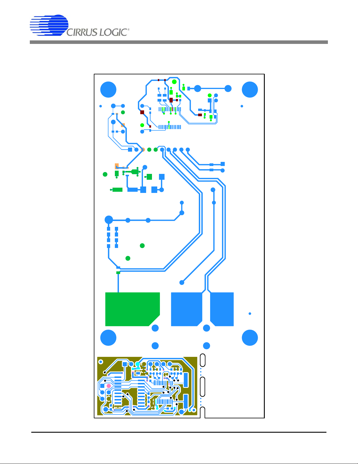
7. BOARD LAYOUT
Figure 23. Component Placement ( Top Silkscreen)
CRD5463PM
16 DS805RD2
Page 17
CRD5463PM
Figure 24. Top Routing
DS805RD2 17
Page 18

CRD5463PM
Figure 25. Bottom Routing
18 DS805RD2
Page 19

8. REVISION HISTORY
Revision Date Changes
RD1 JUL 2010 Initial Release.
RD2 OCT 2010 Updated BOM, schematic, and layer plots to rev B.
CRD5463PM
DS805RD2 19
Page 20

CRD5463PM
Contacting Cirrus Logic Support
For all product questions and inquiries contact a Cirrus Logic Sales Re presentative. To find the one near est to you
go to www.cirrus.com
IMPORTANT NOTICE
Cirrus Logic, Inc. and its subsidiaries ("Cirru s") believe that the information contained in this document is accurate and r eli able. However, the information is su bje c t
to change without notice and is provided "AS IS" without warranty of any kind (express or implied). Customers are advised to obtain the latest version of relevant
information to verify, before placing or ders, that in formatio n be ing relied on is current and comple te. All products a re sold s ubj ect to the term s and conditions of sa le
supplied at the time of order acknow ledgment, includin g those pertaining to warranty, indemni fication, and limitatio n of liability. No responsibility is assumed by Cirrus
for the use of this information, including use of this information as the basis for manufacture or sale of any items, or for infringement of patents or other rights of third
parties. This document is the prop erty o f C irrus a nd b y furn ishing this inform ation, Cirru s grants no lice nse, expres s or implied under any patents, mask work rights,
copyrights, trade marks, trad e secrets or other int ellectual property r ights. Cirr us owns the co pyrights a ssociated wit h the inf ormation contained herein and gives
consent for copies to be made of the inform ation only for us e withi n your o rgani zation w ith resp ect to Cir rus in tegrate d circui ts or other p rodu cts of C irrus. This co nsent does not extend to other copying such as copying for general distribution, advertising or promotional purposes, or for creating any work for resale.
CERTAIN APPLICATIONS USING SEMICONDUCTOR PRODUCTS MAY INVOLVE POTENTIAL RISKS OF DEATH, PERSONAL INJURY, OR SEVERE PROPERTY OR ENVIRONMENTAL DAMAGE ("CRITICAL APPLICATIONS"). CIRRUS PRODUCTS ARE NOT DESIGNED, AUTHORIZED OR WARRANTED FOR
USE IN PRODUCTS SURGICALLY IMPLANTED INTO THE BODY, AUTOMOTIVE SAFETY OR SECURITY DEVICES, LIFE SUPPORT PRODUCTS OR OTHER
CRITICAL APPLICATIONS. INCLUSION OF CIRRUS PRODUCTS IN SUCH APPLICATIONS IS UNDERSTOOD TO BE FULLY AT THE CUSTOMER'S RISK
AND CIRRUS DISCLAIMS AND MAKES NO WARRANTY, EXPRESS, STATUTORY OR IMPLIED, INCLUDING THE IMPLIED WARRANTIES OF MERCHANTABILITY AND FITNESS FOR PARTICULAR PURPOSE, WITH REGARD TO ANY CIRRUS PRODUCT THAT IS USED IN SUCH A MANNER. IF THE CUSTOMER
OR CUSTOMER'S CUSTOMER USES OR PERMITS THE USE OF CIRRUS PRODUCTS IN CRITICAL APPLICATIONS, CUSTOMER AGREES, BY SUCH USE,
TO FULLY INDEMNI FY CIRRUS , ITS O FFICERS, DIRECTOR S, EMPLOY EES, DIST RIBUTORS AND OTHER AGENTS FROM ANY AND ALL LIABILI TY, INCLUDING ATTORNEYS' FEES AND COSTS, THAT MAY RESULT FROM OR ARISE IN CONNECTION WITH THESE USES.
Cirrus Logic, Cirrus, and the Cirrus Logic logo designs are trademarks of Cirrus Logic, Inc. All other brand and product names in this document may be trademarks
or service marks of their respective owners.
Lab Windows and CVI are trademarks of National Instrum en ts Corp oration.
Windows 2000 and Windows XP are eith er trad emarks or registered trademarks of Microsoft Corporation.
Atmel is a registered trademark or trademar k of Atmel Corporation or its subsidiaries.
20 DS805RD2
 Loading...