

Page 1
C
IN
+
Q
B
PFC
CONTROLLER
L
B
R
NTC
R
NTC
CM
Chok e
DM
Chok e
Y-C AP
Y-CAP
FUSE
C1
C2
C3
L1
C4
L2
C5
C
F
AC
X-CAP
X-CAP
X-C AP
V
DC_IN
AN359
Application Note
EMI Filter Modifications when
Replacing L6562 with CS1501
1. Introduction
The Cirrus Logic CS1501 PFC controller is designed to match industry standard critical conduction mode (CRM)
power factor correction (PFC) controllers, with minimal change to conventional designs. This note summarizes the
changes required in the EMI filter circuit of a 120W power supply (PSU), when a ST Microelectronics L6562 PFC is
replaced with a Cirrus Logic CS1501 PFC controller.
2. Overview
When replacing the L6562 PFC controller, care must be taken to ensure the EMI signature is not compromised. Different PFC controllers operate at different frequencies and in different operating modes, requiring EMI filters with
different impedance profiles. An example of maintaining EMI signature when converting from the L6562 to the
CS1501 is described here. For the purpose of simplicity, we will consider only the PFC portion of the PSU circuit.
Cirrus Logic Application Note AN349 gives complete instructions on how to replace the L652.
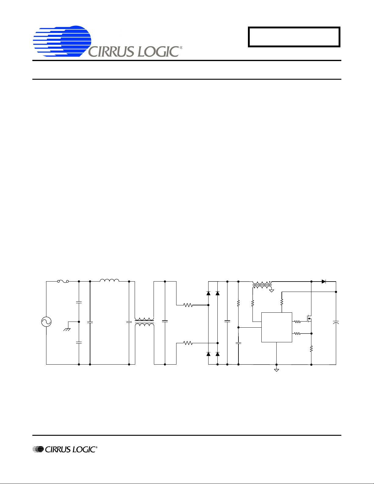
3. Filter Structure
Figure 1 illustrates the components in an EMI filter for a PFC boost using ST Microelectronics L6562.
http://www.cirrus.com
Figure 1. EMI Filter for a 120 W PSU with an L6562 Analog PFC Controller
Copyright Cirrus Logic, Inc. 2011
(All Rights Reserved)
JUL’11
AN359REV1
Page 2
AN359
dl V dtLB=
Table 1 lists the circuit components that influence the EMI filter’s impedance profile.
Description Qty. Designator
Capacitor 4700pF
Capacitor 0.1µF
Inductor 1mH
Capacitor 0.1µF
10 mH
Capacitor 1µF
Resistor 5
Capacitor 4700pF
Capacitor 10nF
2
1
1
1
1
1
1
1
1
Table 1. EMI Filter Components
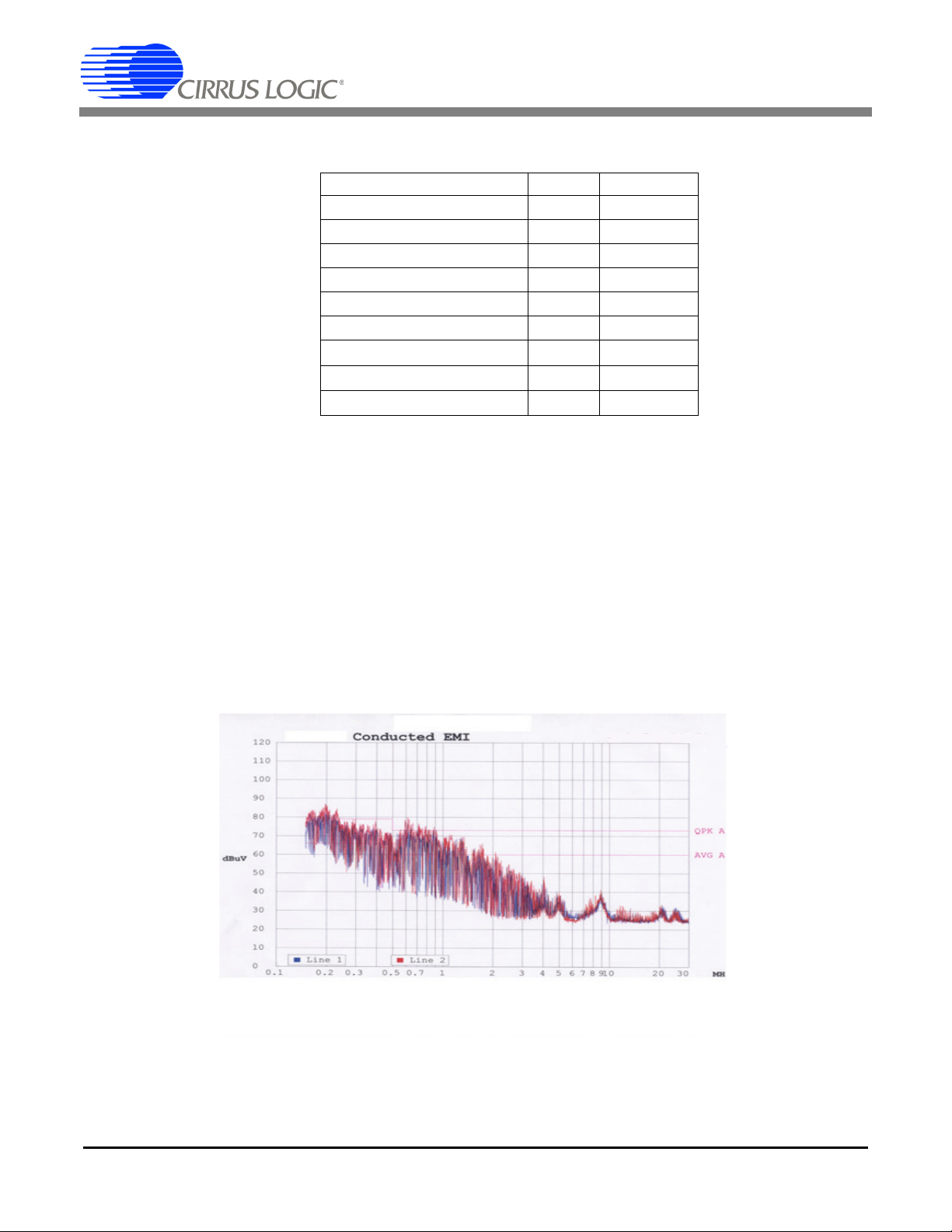
4. Test Results
Initial testing of the circuit demonstrated an increase in the measured EMI when the ST Microelectronics L6562 was
replaced with the Cirrus Logic CS1501. This increased EMI response indicates that the filter has not been designed
to match the CS1501. The use of two NTC resistors, to reduce inrush current, and the bridge rectifier increase the
impedance at the V
CS1501 operates mainly in discontinuous conduction mode (DCM), which requires a lower inductance for the boost
inductor L
bridge and R
. This lower inductance leads to higher switching currents, , being pulled through the
B
resistors. This increases the switching noise at V
NTC
The CS1501 senses the rectified AC voltage (V
inates the filtering use of the capacitor C
in erratic switching (jitter) on the boost FET Q
node. The L6562 controller operates in critical conduction mode (CRM). The digital
DC_IN
.
DC_IN
) as part of its control loop. The bandwidth required for this elim-
DC_IN
. The noise on V
F
, increasing the EMI energy of the PFC.
B
and on the sense voltage into the controller results
DC_IN
C1, C2
C3
L1
C4
L2
C5
R
NTC
C
IN
C
F
Figure 2. EMI Measurement Before EMI Filter Changes
2 AN359REV1
Page 3

5. Changes to the EMI Filter
C
IN
+Q
B
CS1501
PFC
CONTROLLER
L
B
R
NTC
R
NTC
CM
Chok e
DM
Choke
Y-C AP
Y-CAP
FUSE
C1
C2
C3
L1
C4
L2
C5
C
F
AC
X-C AP
X-CAP
X-C AP
V
DC_IN
The following changes were implemented to create an EMI filter optimized for operation with the CS1501:
AN359
- The input capacitor for the PFC is too small. Capacitor C
voltage at V
, eliminating the jitter on the PFC switching.
DC_IN
was increased to 0.47µF. This resulted in a clean
IN
- Capacitor C5 was reduced to 0.47µF.
- The locations of DM choke, L1, and CM choke, L2, were swapped, resulting in two poles at lower
frequencies, formed by L1/ C5 and L2/C4. The common mode (CM) choke L2 had a small differential
inductance, especially compared to L1, which is normal for CM chokes. The resultant pole created by L2 and
C4 is high-frequency, and ineffective in dealing with differential noise. CM choke L2 still formed a differential
filter with C3, and a common mode filter with the Y-capacitors C1 and C2. Its operation was not affected by
moving it to this location.
Figure 3 illustrates a typical CS1501 PFC circuit with the changes to the EMI filter mentioned above.
Figure 3. Typical EMI Filter for a CS1501 PFC Controller
After the changes to the filter were made, the EMI signature was measured and plotted in Figure 4.
AN359REV1 3
Figure 4. EMI Measurement After EMI Filter Changes
Page 4

AN359
Contacting Cirrus Logic Support
For all product questions and inquiries contact a Cirrus Logic Sales Representative.
To find one nearest you go to http://www.cirrus.com
IMPORTANT NOTICE
Cirrus Logic, Inc. and its subsidiaries ("Cirrus") believe that the information contained in this document is accurate and reliable. However, the information is subject
to change without notice and is provided "AS IS" without warranty of any kind (express or implied). Customers are advised to obtain the latest version of relevant
information to verify, before placing orders, that information being relied on is current and complete. All products are sold subject to the terms and conditions of sale
supplied at the time of order acknowledgment, including those pertaining to warranty, indemnification, and limitation of liability. No responsibility is assumed by Cirrus
for the use of this information, including use of this information as the basis for manufacture or sale of any items, or for infringement of patents or other rights of third
parties. This document is the property of Cirrus and by furnishing this information, Cirrus grants no license, express or implied under any patents, mask work rights,
copyrights, trademarks, trade secrets or other intellectual property rights. Cirrus owns the copyrights associated with the information contained herein and gives consent for copies to be made of the information only for use within your organization with respect to Cirrus integrated circuits or other products of Cirrus. This consent
does not extend to other copying such as copying for general distribution, advertising or promotional purposes, or for creating any work for resale.
CERTAIN APPLICATIONS USING SEMICONDUCTOR PRODUCTS MAY INVOLVE POTENTIAL RISKS OF DEATH, PERSONAL INJURY, OR SEVERE PROPERTY OR ENVIRONMENTAL DAMAGE ("CRITICAL APPLICATIONS"). CIRRUS PRODUCTS ARE NOT DESIGNED, AUTHORIZED OR WARRANTED FOR USE
IN PRODUCTS SURGICALLY IMPLANTED INTO THE BODY, AUTOMOTIVE SAFETY OR SECURITY DEVICES, LIFE SUPPORT PRODUCTS OR OTHER CRITICAL APPLICATIONS. INCLUSION OF CIRRUS PRODUCTS IN SUCH APPLICATIONS IS UNDERSTOOD TO BE FULLY AT THE CUSTOMER'S RISK AND
CIRRUS DISCLAIMS AND MAKES NO WARRANTY, EXPRESS, STATUTORY OR IMPLIED, INCLUDING THE IMPLIED WARRANTIES OF MERCHANTABILITY
AND FITNESS FOR PARTICULAR PURPOSE, WITH REGARD TO ANY CIRRUS PRODUCT THAT IS USED IN SUCH A MANNER. IF THE CUSTOMER OR
CUSTOMER'S CUSTOMER USES OR PERMITS THE USE OF CIRRUS PRODUCTS IN CRITICAL APPLICATIONS, CUSTOMER AGREES, BY SUCH USE, TO
FULLY INDEMNIFY CIRRUS, ITS OFFICERS, DIRECTORS, EMPLOYEES, DISTRIBUTORS AND OTHER AGENTS FROM ANY AND ALL LIABILITY, INCLUDING ATTORNEYS' FEES AND COSTS, THAT MAY RESULT FROM OR ARISE IN CONNECTION WITH THESE USES.
Cirrus Logic, Cirrus, and the Cirrus Logic logo designs are trademarks of Cirrus Logic, Inc. All other brand and product names in this document may be trademarks
or service marks of their respective owners.
6. Summary
Filters ease the design and qualification process of a PSU by suppressing EMI. The adaptation of an EMI filter to
optimize performance when converting from an L6562 to the CS1501 controller was illustrated. The necessity of
measuring EMI, and understanding the factors involved in effectively filtering were also described.
7. Reference
Cirrus Logic Application Note: AN349 “Migrating from the L6562 to the CS1501 Power Factor Correction IC”.
4 AN359REV1
 Loading...