

Page 1

AN348
Application Note
GETTING STARTED WITH THE AUDIO DSP EVALUATION
KITS FROM CIRRUS LOGIC
1. INTRODUCTION
The following sections will provide step-by-step instructions to explain how to get started with the Evaluation Kits for Audio DSP
products from Cirrus Logic. This is a generic document as its principle applies to all current Audio DSP families from Cirrus Logic
— the CS48500, the CS470xx Audio SoCs, and the CS49531x / 4970xx.
An advanced audio processing design is created and will be used as an example to illustrate the practical work with the
DSP Composer™ tool and a CDB48560 evaluation board. The given e xample is more complex than the example projects
included in the evaluation board software package. It also shows how to use the pre-defined blocks and primitives when using
the DSP Composer GUI.
A Q&A section is included at the end of this document.
2. GETTING STARTED
2.1 Up-front information and preparation
Please prepare the following essential information about your target application before co ntacting Cirrus Log ic:
• The basic technical design requirements including any 3rd party IP support such as the support of specific multichan nelaudio formats or standards.
• The general project schedule and anticipated volume information.
• Your contact details.
With these details on hand, your local Cirrus Logic Distribution partner or sales offices can easily identify the 'best fit' Audio DSP
for your application. Cirrus Logic offers a great variety of Audio DSP-products, which are widely compatible — whether your
design needs a cost-effective, entry-level audio DSP such as a CS48500-DSP or a high-performance multichannel audio decoder
such as the CS49700.
If applicable, Cirrus Logic needs to contact the relevant third party to get approval prior to providing samples or software.
Please contact your local Cirrus Logic sales representative or Distribution partner for details.
The evaluation board software is provided on the Cirrus Logic web site http:/www.cirrus.com
specific to the DSP of your choice and browse to the Resources section.
Within the software suite, you will only have access to modules and functions for which you have appropriate licences in place.
If you require access to disabled blocks, you will need to obtain the licences from the third-party licensor first before Cirrus Logic
is authorized to send you the specific code.
Cirrus Logic provides comprehensive technical documentation such as evaluation board manuals, data sheet specifications, or
application notes which will be installed during the evaluation board software setup. The default path for all documents is
C:\CirrusDSP\doc\. Note that application notes for the individual processing blocks such as for third-party, IP-based decoders are
provided with the individual setup files.
. Please refer to the web site section
All Cirrus Logic DSPs are SRAM-based and can be upgraded in the field or during evaluation.
Copyright Cirrus Logic, Inc. 2011
http://www.cirrus.com
(All Rights Reserved)
MAR ‘11
AN348REV2
Page 2
AN348
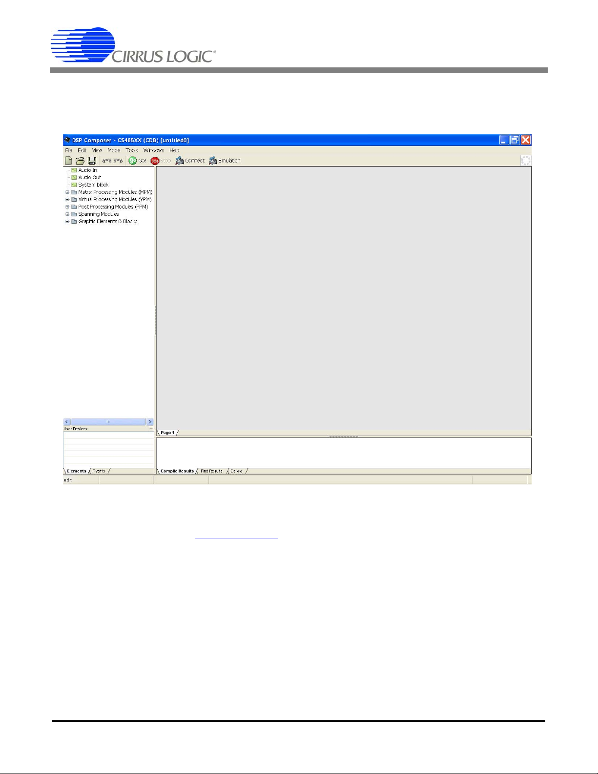
2.2 The Essential Set-up
The evaluation boards are connected to standard PCs with Windows XP® operating systems via USB. After a successful
installation of the evaluation board software, the DSP Composer GUI can be started. Your computer screen should look like the
following:
The GUI can also be used in emulation mode (without any evaluation board connected to the host PC).
Please refer to theCDB48500-USB Evaluation Kit guide from Cirrus Logic for a basic introduction to the minimum hardware set-
up. This is available at http://www.cirrus.com
START
Program Files Cirrus Logic DSP menu after installation.
. These specifications are also accessible per the
2.3 Using the DSP Composer GUI, Project Example
This section shows how to build a project with multiple audio I/Os and some customized audio processing using the DSP
Composer GUI.
Let us consider designing an audio system with the following features:
• 4 Analog Inputs, 6 Analog Outputs
• Customized Audio Processing Chain as Follows:
- High-pass and low-pass filters for the input channels
- Mixer with 4 inputs to create 6 output channels
- 6-channel, 4-band parametric EQ
- Sine wave test-tone generator
2 AN348REV2
Page 3
AN348
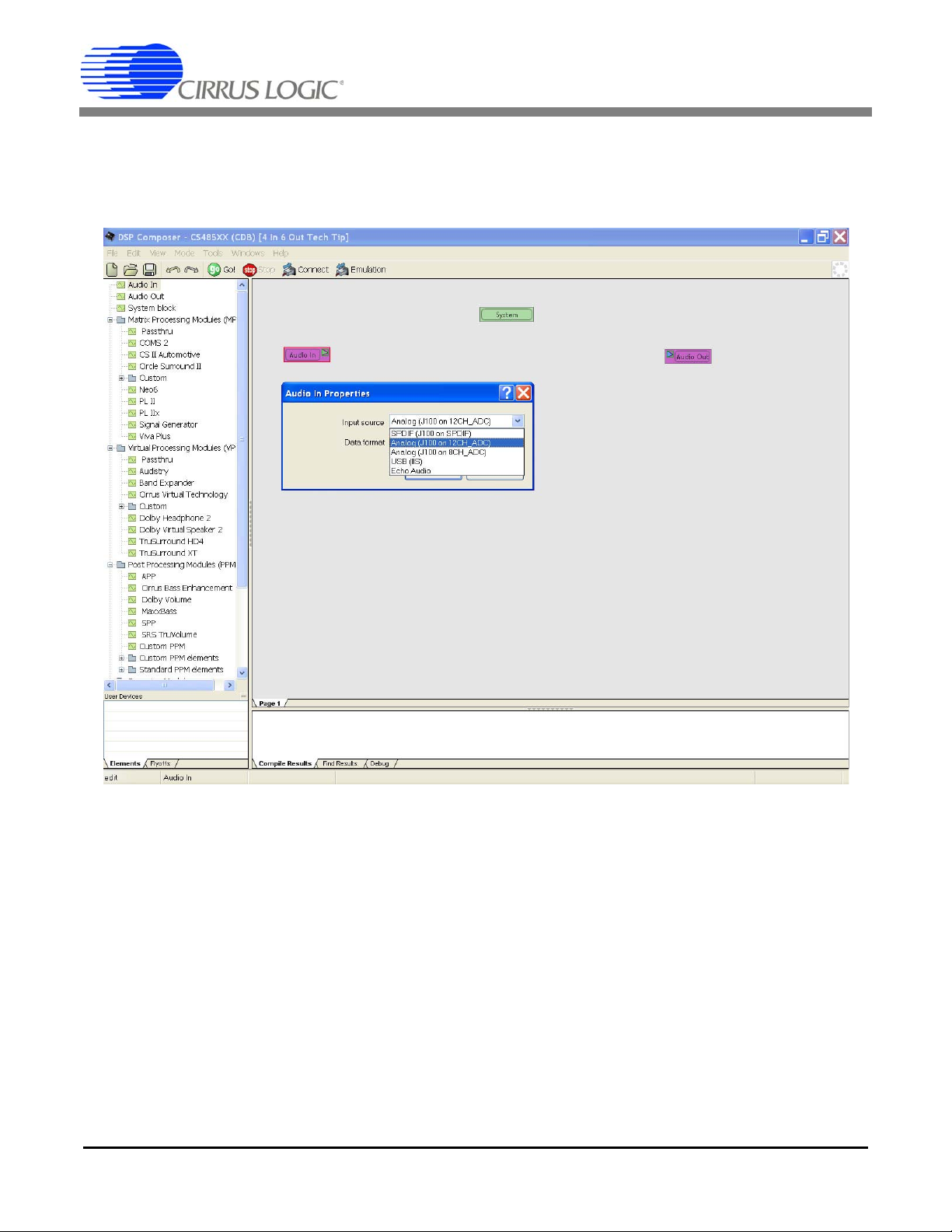
First, drag the SYSTEM block from the menu on the left-hand side. When positioning the SYSTEM block on the virtual workspace
or canvas, some parameters can be set. Please leave everything set to default for now.
Next, we define the audio inputs and outputs by another simple drag-and-drop operation. Fo r thi s example, le t us select anal og
inputs for the input block in the Properties menu and some analog outputs per the default settings.
AN348REV2 3
Page 4
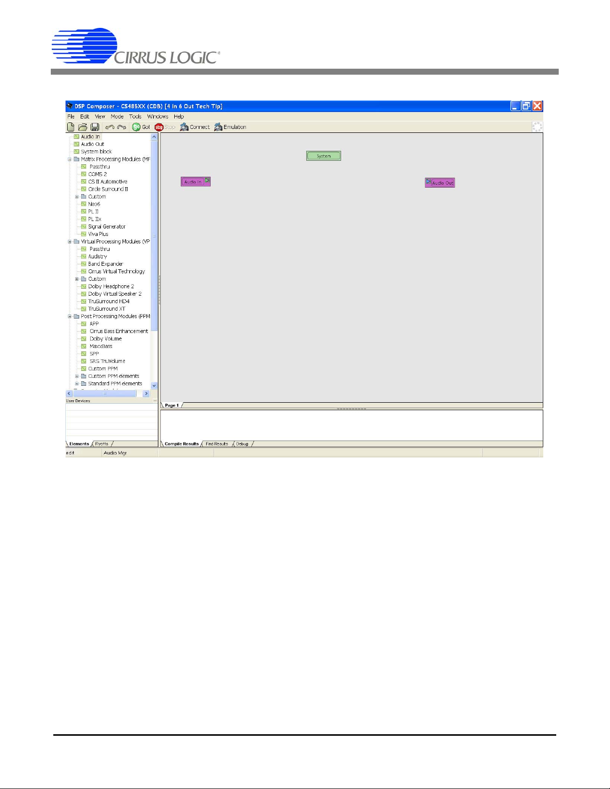
Your workspace or canvas shoul d no w lo ok similar to this:
AN348
Our example project does not include any matrix decoders or virtualizing modules.
Therefore, we select the corresponding Passthru-Matrix processing module (MPM) and Passthru-Virtual processing module (or
VPM) from the selection menu on the left-hand side to allow a simple pass-through function.
The next step is to start with creating our own custom Post Processing module (PPM). Drag the Custom PPM block on to the
canvas. Here we have named the block My PPM. We also need to add another final stage — the audio manager module, which
can be found under Standard PPM elements. This connects the My PPM module to the audio outputs.
4 AN348REV2
Page 5

The top-level diagram now looks like this:
AN348
Now let us add another page to the Post Processing block to keep the top-level PPM diagram clean. To do this, we need to open
the custom PPM block named My PPM by double-clicking it. Then move your mouse pointer to the bottom of the canvas and
right-click to select Insert to add another page. After double-clicking on it, you may also want to rename the page to something
such as Processing.
AN348REV2 5
Page 6

Our workspace or canvas now looks like this:
AN348
Let us return to the Schematic page now. We will be using so-called fly-offs to connect elements between the Schematic and the
Processing page.
The creation of new fly-offs for the design's input and output signals is easy: Mark the first four input channels L, C, R, and Ls on
the Schematic page using your mouse. Then, change to the Wire mode using <CTRL>+<W>, left-click, hold and drag four wires
and then click the right mouse button. This will result in four blue labels. Double-click these to give them some individual names.
Apply the same procedure to the six output channels: L, C, R, Ls, Rs, and Lb.
6 AN348REV2
Page 7

Our schematic now looks like this:
AN348
Now, mark and copy all fly-offs marked in blue and insert them into the Processing page. Refer to Section 5.1 in the DSP
Composer manual for more details on how to use fly-offs and associated wiring techniques.
NOTE:
DSP Composer verifies that fly-offs used in a design are properly connected in the fly-offs-page accessible in the lower
left corner, see the screenshot above.
You will also notice that unused signals in standard elements such as the PPM block will be marked green, whereas
connected channels will appear black during the wiring process.
The next step is to add some audio filters and other au dio processing functions for our design example. Double-click on the
Custom PPM Elements menu on the left to expand and browse through the various element categories such as filters, mixers,
and other functions which are refe rre d to as Primitives in the documentation.
Drag-and-drop the following pre-defined blocks onto the workspace:
• A high-shelf filter and a low-pass 18 dB / Octave filter from the Filters section
• A multi-band parametric EQ available in the filters' m-band, n-band PEQ menu. Enter 6 channels and 4 bands per channel
into the pop-up box.
• A Sine Wave Generator from the Generators selection.
• A signal-presence detector taken from the Meters menu
• A 4 x 6 channel mixer from the Mixers' Custom menu. Enter the corresponding number of channels into the pop-up bo x.
• A 5 inputs, 4 outputs router from the Routers' Custom menu. Enter the number of I/Os into the pop-up box.
AN348REV2 7
Page 8

Here is what the workspace looks like now:
AN348
Next, we need to create additional three instances of the high-shelf and low-pass filter blocks. Simply select the individual blocks,
press <CTRL>+<D> (for duplication), and enter the required number of blocks to be re produced. Re-arrange all blocks and use
<CTRL>+<W> to change to Wire mode, then connect all elements. Refer to the DSP Composer Manual Data Sheets DS704 for
more advanced wiring modes and interconnection details.
As a result, we have created the following audio processing chain. The 5 x 4 router allows an easy assignment of the sine wave
generator signal to test individual channels. The presence detectors are for monito ring purposes of either test tones or input
signals which are digitized by the on-board CODEC.
8 AN348REV2
Page 9
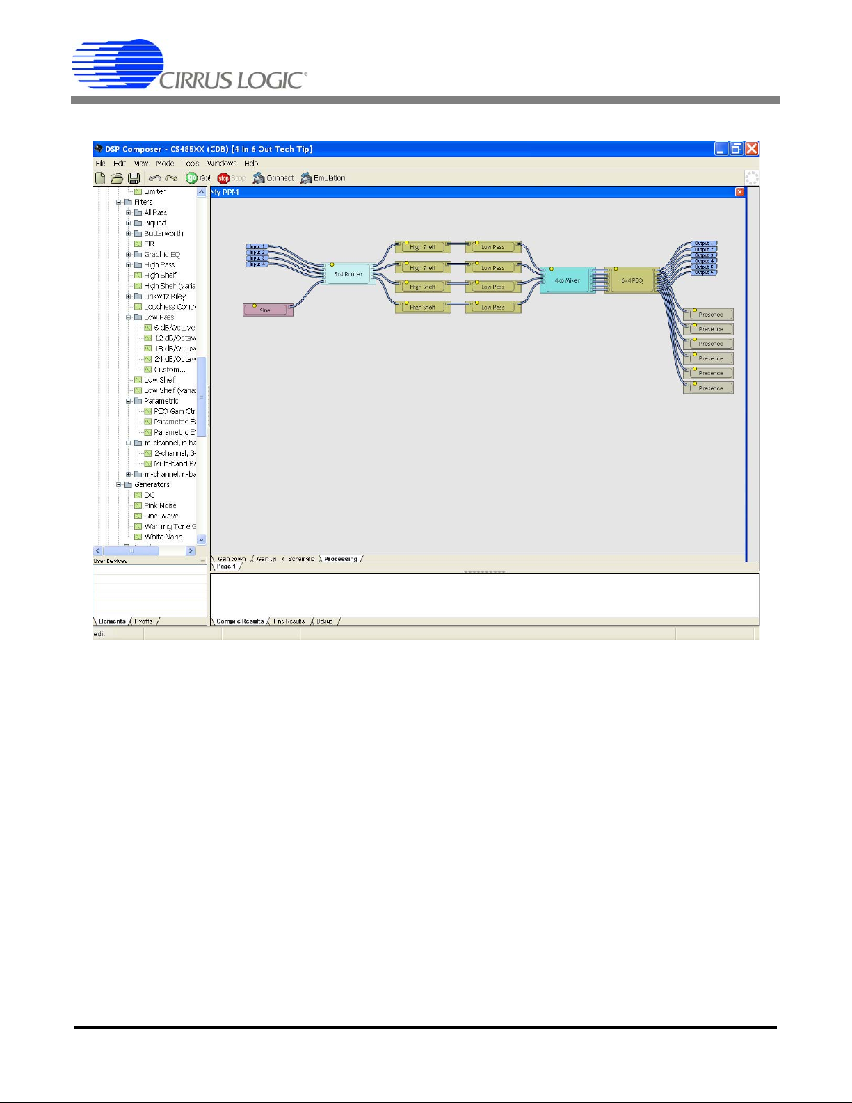
The canvas or workspace should now look like this:
AN348
Y ou will notice that there are no limitations how to interconnect or arrange the individual processing stages or primitives. As long
as the audio processing fits the DSP's internal resources, the design engineer has the ultimate freedom to create any customized
audio processing stage to meet the design requirements.
Now that the customized audio stage, My PPM, is finished, we need to complete the top-level schematic diagram.
Once the wiring is completed, the top-level schematic will look like this. Y ou may also want to add a text label or bump panel taken
from the Graphics Elements and Blocks section at the very bottom of the selection menus on the left-hand side of the GUI.
AN348REV2 9
Page 10

AN348
Once our project is complete, save it. To load our project onto the appropriate evaluation board, we need to build and compile it.
To do this, verify that the evaluation board is connected to your PC via USB and powered up, then click CONNECT and GO. The
DSP Composer GUI will enter the gesture mode and your mouse pointer will turn into a hand icon, which allows the adjustment
of control settings.
The DSP Composer GUI will download the audio processing configuration to the CDB48500 evaluation board allow ing you to
evaluate the functions.
Consult the CDB48500-USB Evaluation Kit Guide for more details on the board setup and the DSP Co mposer section for the
basic processing blocks or elements, wiring details, and the so-called gesture mode.
10 AN348REV2
Page 11

AN348
3. Q & A
Q: Where can I find more technical documents for your Audio DSP Evaluation boards and tools?
A: Evaluation board manuals including schematics can be downloaded from our web site http://www.cirrus.com. Application
notes for individual processing blocks and further documentation are available either from your local Cirrus Logic sales office
or after the installation of the Evaluation Board Software.
Q: I am having difficulties connecting your Audio DSP evaluation board to my PC and/or I am seeing communications error
messages.
A: We recommend carefully checking any firewall software or similar programs. If you see any message about allowing
coyote_proxy_server to run, be sure to allow it.
This blue button, labeled CDM for Cirrus Device Manager, should be visible in your PC's taskbar and should indicate your
evaluation board as an active device.
If the button is grey, but not blue, you need to verify the installation and the evaluation board detection. Refer to the
Troubleshooting Guide in the DSP Evaluation Kit Guide.
Secondly, check the following: Browse to the C:\CirrusDSP\bin folder and search for *.bit files. There should be only one
usbfpga_xyz.bit.bit file. Delete any other file, if it exists.
Q: What if I need a DSP function that is not included in the supplied modules?
A: There are three methods to integrate customized audio processing blocks into DSP Composer:
1) Define your own audio processing block using DSP Composer as explained in Step 3) Using the DSP Composer GUI,
Project Example above. Low-level, pre-defined elements or primitives are available, such as single FIR filters which can
be used to implement your individual design.
2) Contact Cirrus Logic to create a new audio processing block for you.
3) Use the Cirrus Logic Integrated Development Environment (CLIDE) tool set to compile your own algorithms using C or
assembler. See below.
Q: We need to program the Audio DSP using C or assembler to incorporate proprietary processing. How will Cirrus Logic
support this?
A: Cirrus Logic provides a tool chain named CLIDE (Cirrus Logic Integrated Development Environment) to support both
programming in C as well as at the assembler level.
AN348REV2 11
Page 12

REVISION HISTORY
Contacting Cirrus Logic Support
For all product questions and inquiries contact a Cirrus Logic Sales Representative.
To find one nearest you go to http://www.cirrus.com
IMPORTANT NOTICE
Cirrus Logic, Inc. and its subsidiaries ("Cirrus") believe that the information contained in this document is accurate and reliable. However, the information is subject
to change without not ice and is provi ded "AS I S" without warran ty of any kind (express or implied). Customers are advised to obtain the latest version of relevant
information to verify, before placing orders, that information being relied on is current and complete. All products are sold subject to the terms and conditions of sale
supplied at the time of order acknowle dgment, including tho se pertaining to wa rranty, indemnification, an d limitation of liability. No responsibility is assumed by Cirrus
for the use of this information, including use of this inform ation a s the basis for m anufactur e or sale of an y items, or for i nfringement of patents or other rights of third
parties. This document is the property of Cirrus and by furnishing this information, Cirrus grants no license, express or implied under any patents, mask work rights,
copyrights, trademarks, trade secrets or other intellectual pro perty rights. Cirrus owns the copyr ights associated with the information con tained here in and gives consent for copies to be made of the information only for use within your organization with respect to Cirrus inte grated circuits or other products of Cirrus. This consent
does not extend to other copying such as copying for general distribution, advertising or promotional purposes, or for creating any work for resale.
CERTAIN APPLICATIONS USING SEMICONDUCTOR PRODUCTS MAY INVOLVE POTENT IAL RISKS OF DEATH, PERSONAL INJURY, OR SEVERE PROPERTY OR ENVIRONMENTAL DAMAGE ("CRITICAL APPLICATIONS"). CIRRUS PRODUCTS ARE NOT DESIGNED, AUTHORIZED OR WARRANTED FOR USE
IN PRODUCTS SURGICALLY IMPLANTED INTO THE BODY, AUTOMOTIVE SAFETY OR SECU RITY DEVICES, LIFE SUPPOR T PRODUCTS OR OTHE R CRITICAL APPLICATIONS. INCLUSION OF CIRRUS PRODUCTS IN SUCH APPLICATIONS IS UNDERSTOOD TO BE FULLY AT THE CUSTOMER'S RISK AND
CIRRUS DISCLAIMS AND MAKES NO WARRANTY, EXPRESS, STATUTORY OR IMPLIED, INCLUDING THE IMPLIED WARRANTIES OF MERCHANTABILITY
AND FITNESS FOR PARTICULAR PURPOSE, WITH REGARD TO ANY CIRRUS PRODUCT THAT IS USED IN SUCH A MANNER. IF THE CUSTOMER OR
CUSTOMER'S CUSTOMER USES OR PERMITS THE USE OF CIRRUS PRODUCTS IN CRITICAL APPLICATIONS, CUSTOMER AGREES, BY SUCH USE, TO
FULLY INDEMNIFY CIRRUS, ITS OFFICERS, DIRECTORS, EMPLOYEES, DISTRIBUTORS AND OTHER AGENTS FROM ANY AND AL L LI ABI LI TY, I NCLUDING ATTORNEYS' FEES AND COSTS, THAT MAY RESULT FROM OR ARISE IN CONNECTION WITH THESE USES.
Cirrus Logic, Cirrus, and the Cirrus Logic logo de signs ar e trade mar ks of Cirrus Logic, Inc. All other br and a nd pro du ct nam es in this docu me nt may be tradem arks
or service marks of their respective owners.
Revision Date Changes
REV1 DEC 2010 Reformatted existing “Tech Tips” document. Updated screenshots.
REV2 MAR 2011 Corrected minor formatting issues.
AN348
12 AN348REV2
 Loading...