

Page 1

Cirrus Logic CobraNet® Developer Tips for
1. INTRODUCTION
AN335
CS1810xx / CS4961xx Devices
This document contains a compendium of information useful in the development of products based on the Cirrus
Logic CS1810xx and CS4961xx CobraNet
engineers, which are new to the development of designs using CobraNet devices.
The information required for product development is also contained in various application notes, data sheets and
manuals available on the Cirrus Logic and CobraM C we bsit es .
The CobraMC website is a password protected site which provides support for CobraNet OEMs. Access to this site
is provided to qualified customers upon execution of a standard non -disclosure agreement (NDA) with Cirrus Logic.
Please contact your local Cirrus Logic distributor or sales representative in order to execute an NDA and gain access
to this site and any other protected materials described in this document.
®
devices. It is intended as an initial guideline for hardware and software
1.1 Required References
It is compulsory to obtain and study the following references:
1. CobraNet Programmer's Reference Manual - Contains information on the control and setup of CobraNet devices. Most of the manual is a reference describing each of the configuration variables used
to control and monitor a CobraNet interface.
2. CobraNet Hardware User's Guide - This is the data sheet for the CS181xx/CS4961xx chips. It contains a schematic for the CM-2 CobraNet modul e which ca n be use d as a re fe re nc e de sig n.
3. CobraNet Discovery User's Manual - This manual is installed with CobraNet Discovery. CobraNet
Discovery is an application used to monitor and control CobraNet devices and to update the firmware
of CobraNet devices.
4. Application Notes:
a. CobraNet Audio Routing Primer — Basic information about setting bundle n umbers and channel
assignments
b. Bundle Assignments in CobraNet Systems — Considerations and guidelines when setting up
audio bundles in a CobraNet installation. Ramifications of different settings and how they impact
network performance and utilization.
c. Integrating CobraNet into Audio Products — Basic hardware design guidelines for CobraNet
products. Much is focused on integrating CobraNet modules into audi o equipment but a wealth of
applicable information of a general nature and pertaining to chips is contained here.
d. AN312, CobraNet Clocking Modes — This application note is required for any manufacturer that
intends to use any clocking mode other than the defa ult. Proper use and support of CobraNet audio
clocks is essential to correct operation of the individual devices and the audio network.
e. AN279, Controlling and Monitoring DSP Conductor™ Configurations — This application n ote
describes how to access the R/W variables used to control the DSP parameters created with DSP
Conductor.
f. AN334, CS1810xx / CS4961xx Bing-up Instructions — This application note describes how to
get a newly manufactured CobraNet design up and running using either a pre-programmed flash or
2C®
I
debugging tools.
http://www.cirrus.com
Copyright © Cirrus Logic, Inc. 2008
(All Rights Reserved)
NOVEMBER '08
AN335REV1
Page 2
2. CobraNet DISCOVERY
The CobraNet Discovery Software (also referred to as 'Disco') should be downloaded and installed. Disco
provides the following indispensable functions:
• Discovers and displays all CobraNet devices on the network.
• Provides a user configurable watch window to monitor device health.
• Provides a firmware update function.
• Assigns IP addresses to CobraNet devices. CobraNet device IP addresses are dynamic by default.
A CobraNet interface will not have an IP address when powered up. Disco is used to automatically
or explicitly assign IP addresses when needed.
• Provides a GUI interface for changing commonly used configuration variables.
• Provides an advanced interface for changing or monitoring any CobraNet variable via SNMP.
• Provides a report generation function useful for documenting configuration and troubleshooting.
Read the CobraNet Discovery manual that is installed with the program.
3. FIRMWARE
It is important to select the correct Firmware when updating the CobraNet Flash memory as the Firmware
needs to match the actual hardware.
AN335
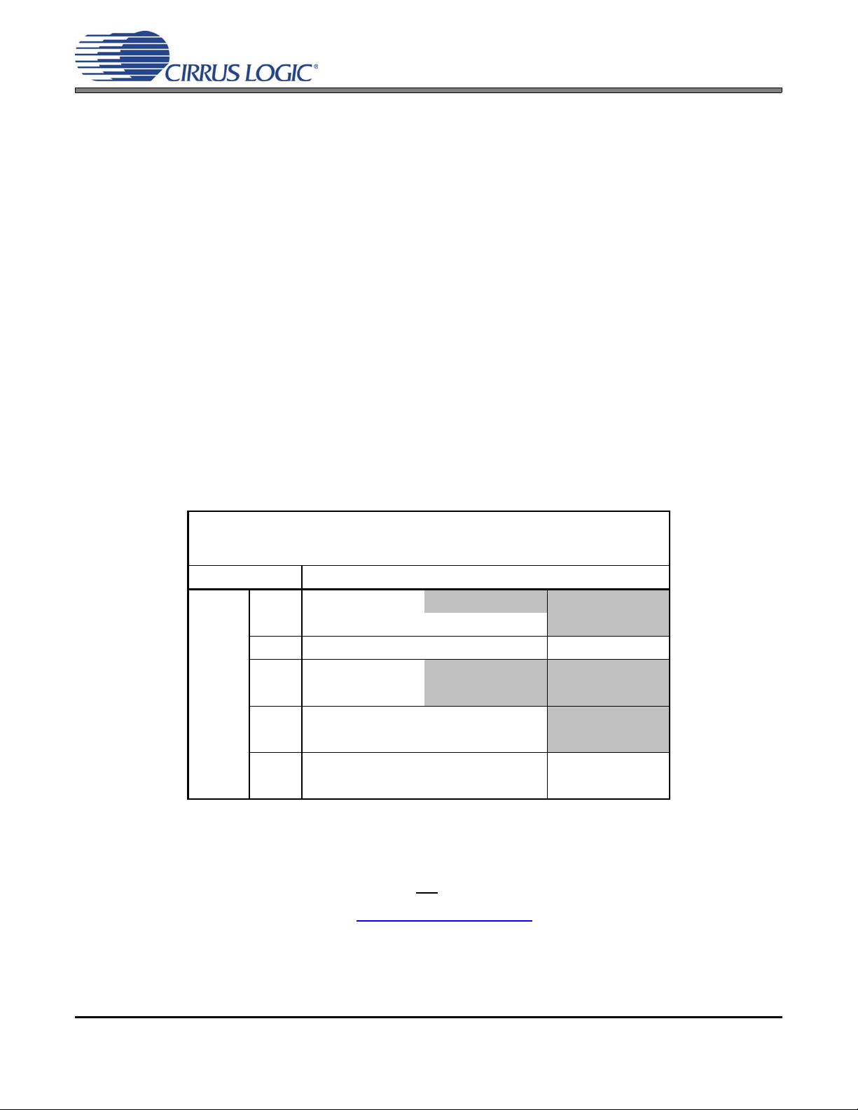
CobraNet Firmware Matrix
Platform Firmware that will run on platform
181002 cm18100_2_11_x.bin
181012 cm18100_2_11_x.bin cm18101_2_11_x.bin
181022 cm18100_2_11_x.bin cm18101_2_11_x.bin cm18102_2_11_x.bin
CM-2
and
chip-
based
platforms
496102
496112
496122
Note:
The CO2-boards from Atterotech, Inc. use the I²S digital audio format mode on the serial audio in-
terface or SSI channels. Standard code will not
Please contact Atterotech, LLC at http://www.atterotech.com
images for Atterotech boards.
cm49610_2_11_x.bin
cm18100_2_11_x.bin
cm49610_2_11_x.bin
cm18100_2_11_x.bin
cm49610_2_11_x.bin
cm18100_2_11_x.bin
cm49611_2_11_x.bin
cm18101_2_11_x.bin
cm49611_2_11_x.bin
cm18101_2_11_x.bin
Table 1: CobraNet Firmware Matrix
work properly.
cm49612_2_11_x.bin
cm18102_2_11_x.bin
for support on binary code firmware
2 AN335REV1
Page 3

AN335
1. The latest version of CobraNet firmware is available on the Cirrus Logic website or on the CobraMC
website.
http://www.cirrus.com
http://www.peakaudio.com/cobramc/
2. Specific firmware files (.bin files) are required fo r specific CobraNet devices. These are available for
web download. Figure 1 above illustrates which firmware is compatible with which CobraNet devices.
3. CobraNet firmware is stored in external FLASH memory. Firmware must be loaded to FLASH before
the device will function.
a. FLASH memory can be pre-programmed before soldering to the circuit board.
b. FLASH memory can be programmed in a development environment using an adapter card and
software provided by Cirrus logic. The software is called CID and, along with CobraNet Discovery,
can be used to load firmware to FLASH. The CID adapter connects to the CobraNet chip via the
debug header JP1- CON4 as shown in the schematic in the appendix of the CobraNet Hardware
User's Guide.
c. Refer to Cirrus Logic AN334, CS1810xx / CS4961xx Bing-up Instructions provided with the CID for
complete instructions.
4. CobraNet Discovery is primarily an end user tool and contains a feature that prevents the user from
loading incorrect firmware to a device. It may be necessary to override this feature when updating a
device's firmware in a development environment so that unrecognized firmware can be selected and
loaded. The update protection mechanism can be overridden by doing the following:
a. Make sure CobraNet Discovery is NOT running.
b. Open the cndisco.ini file found in the Program Files\Cirrus Logic\CobraNet Discovery folder
c. Add the line: Advanced Feature=1 to the [Configuration]
— Public
— Requires NDA
Note: The line is case and space sensitive.
[Configuration]
Advanced Feature=1
d. Save and close cndisco.ini.
e. Launch CobraNet Discovery.
f. Now, when the firmware selection screen is displayed, there will be a new checkbox labeled: Show
all Firmware Versions.
g. Check this option and all firmware in the firmware directory will be available for selection.
Warning: Use this option carefully as it will be possible to update incompatible firmware with
this option enabled.
h. Once this has been done, CobraNet Discovery will then enter the code vers ion into its database and
it will be recognized thereafter without need to check Show all Firmware Versions.
AN335REV1 3
Page 4

4. FIRMWARE CUSTOMIZATION
CNCustom is a program available to qualified manufacturer's which is used to create firmware binary image
files with manufacturer specific default configuration settings. Most configuration variables described in the
Programmer's Reference can be assigned other than default settings. Although any configu ration variable's
default value can be changed, the most common and useful changes are to:
• sysDescription — Identify the device with an ASCII string
• firmwareMfgID — A Cirrus Logic assigned integer defining the manufacturer of the device. Please contact your local Cirrus sales representative for a manufacturer ID number.
• firmwareMfgProductID — A manufacturer assignable integer firmwareMfgVersion — A manufacturer-assignable integer
Use of CNCustom will result in creation of a device specific firmware image that should be given a unique
file name. It is important to observe proper naming conventions when choosing file names.
5. FIRMWARE NAMING CONVENTIONS
CobraNet firmware binary image files adhere to a standard naming convention necessary for recognition by
CobraNet Discovery and the Python manufacturing script.
As an example, the file name cm1800_0_11_6_2.bin indicates that this is build 2 of pre-release version
0.11.6 targeted at a CS18100 chip with two MAC/PHY chips attached.
AN335
• Decode for standard Cirrus supplied firmware:
The first two alpha characters will be cm or cs., i.e. cm1800_2_11_6.bin
cm indicates a build for a dual MAC/PHY interface
cs indicates a build for a single MAC/PHY interface
• The next characters before the f irst '_' can be anyth ing but, in the case of Cirrus standard builds , indicates the target device cm1800_2_11_6.bin.
This could be:
18100, 18101, 18102, 49610, 49611, or 49612 for 32-bit platforms.
12, 14, or 18 for 8x8, 16x16, or 32x32 channel CM-1 builds respectiv ely .
• The digits following the first '_' and separated by underscores indicate the firmware revision
cm1800_2_11_6.bin.
• A leading 0, instead of the 2, as in this example, wo uld ind icate a pr e-re lease version. In th is ca se there
will often also be a fourth digit indicating the build number. i.e. _0_11_6_3 indicates build 3 of a pre-release version. Build numbers may, but are typically not, included in the released code filename.
• A manufacturer can name firmware created by them as desired provided that the naming convention is
followed.
• The first part of the name can be any string. The first underscore '_' indicates the beginning of the rev
number is indicated.
• For example, a manufacturer could use a file name similar to the following:
AudioMatic3_2_11_6.bin
Where AudioMatic3 is defined by the manufacturer, but all characters following the first underscore adhere
to the revision indication convention. Note that you cannot put underscores in the leading string. The revision numerals are delimited by underscores and must always be present in the proper locations. Underscores cannot be used in the name for any other purpose.
4 AN335REV1
Page 5

6. MAC ADDRESSES
• Each CobraNet device must be assigned a unique MAC address. Cirrus Logic provides a Python script
that is used to assign unique MAC addresses. This is done via the network after valid firmware ha s been
loaded to FLASH. The process updates the existing firmware as well as updating the MAC address. Instructions for downloading and installing the requ ired P ython fr amework as we ll as for us e of the script
are provided by Cirrus to qualified manufacturers.
• It is useful when using pre-programmed FLASH to prepr ogram the F LASH with the lowest-common-d enominator firmware (see Table 1 on page 2) in order to insure that the stock of FLASH chips on hand
can be used with any version CobraNet chip. Subsequen t use of the Python man ufacturing script is then
used to update the firmware with the correct MAC address and with the latest firmware appropriate to
the target platform.
• MAC addresses are available from the IEEE or can be provided to qualified manufacturers by Cirrus Logic.
7. DSP CONDUCTOR™
• This is a development tool used by manufacturers to ea sily create DSP code for the CS4961xx family of
devices.
• A downloadable binary image incorporating user selected DSP functions, and based on current CobraNet firmware, can be created using DSP Conductor.
AN335
• Distribution to, or use by, end users of DSP Conductor is strictly prohibited.
• Refer to the application note AN279 for instructions on how to control DSP functions.
• DSP Conductor, as a development tool, loads DSP code to a target device's RAM, not to its FLASH
memory. Once the design is finished and stable, use Tools > Gener ate Deliverables > Patch Image… to
create a firmware file which can be downloaded to the target device's FLASH memory by using CobraNet
Discovery.
• Refer to the PDF manual included with DSP Conductor for usage instructions
8. BOARD HARDWARE DESIGN CONSIDERATIONS
• The CM-2 design published in the appendix of the CobraNet Hardware User's Guide can be used as a
reference design. Note that this is a proven design, so deviatio ns from this design example ar e strong ly
discouraged.
• It is also recommended that the design guidelines and tips presented in the “Integrating CobraNet Into
Audio Products” application note be respected.
• Good supply bypassing, grounding and stable power supplies are essential to good performance, particularly in the areas of the MAC/PHY supply and PLL supply (1.8V analog supply on the chip). These
are particularly sensitive to stability and noise issues.
• The following signals are required to be present / connected to the CM-2 boards in order to operate p roperly with the standard firmware.
– All GND and 3.3 V supply lines connected and properly bypassed.
– The CM-2 provides MCLK at 12.288 MHz to an external audio source/sink; which is required to
operate in slave mode and left-justified digital audio format.
– The CM-2 provides a SCLK signal at 64 * LRCK = 3.072 MHz to an external audio source/sink,
which is required to operate in slave mode.
AN335REV1 5
Page 6

AN335
which is required to operate in slave mode.
– The CM-2 provides a LRCK signal at 48 kHz (Sampling Rate or Fs) to an external audi o source/sink,
which is required to operate in slave mode.
– The external audio source/sink provides digital audio data to / receives from the CM-2 module.
– An external active-low reset signal in accordance with the hardware specifications is applied.
• There are two deviations from the standard reference design that can be safely made at the designer's
option:
– Refer to U4 on page 2 of 7 of the reference desig n. This device is used to select between an external
audio master clock and the local VCXO generated master audio clock. This MUX can be omitted
when use of an external master clock is not required. The master audio clock can be connected from
the VCXO to the CobraNet processor. The series termination resistor should be retained. If the clock
will be used by more than one load then it should be buffered. Application Note AN312 should be
carefully read and understood if other than the standard clocking mode 0x00 will be used.
– Refer to U11 and U10C on page 4 of 7 of the reference desig n. The audio word clock (FS1) is taken
from pin 22 or pin 14 of the CobraNet chip depending on whether or not a 16x16 cha nne l device is
used. This circuit will automatically select the correct pin based on clock activity. If the design does
not require this flexibility (most do not), then FS1 can be hardwired from Pin 14 for 16x16 channel
devices or from Pin 22 for other devices. R53, the series termination resistor, should b r etained.
6 AN335REV1
Page 7

9. CobraNet SILICON SERIES DEVICE DIFFERENCES
AN335
The CS18100, CS18101, CS18102, CS49610, CS49611 a nd CS49612 are members of the Cirrus Logic CobraNet
Silicon Series of devices. They differ from each other based on the presence of a user-programmable audio DSP
core and in the number of audio channels supported. They are otherwise identical devices.
• The package and pinout are the same for all three parts.
• The word clock (FS1) changes from pin 22 to pin 14 for the CS18102 and CS49612. See Figure 2.
• The bit clock (SCLK) is the same for all parts.
• For all parts, regardless of which pin is used for FS1, DAO1_LRCLK and DAI1_LRCLK should be tied to-
gether.
• The SSI channels run at 128FS (4 channels per SSI) for CS18102/CS49612 and 64FS (2 channels per SSI)
for all other parts.
•Only DAO1_DATA0 and DAI1_DATA0 are active for CS18100/CS49610.
All three lines, DAO1_DATA[3:0] and DAI1_DATA[3:0] are active for all other parts.
• The firmware running on each part is specific to that part.
• The following CobraNet features are only available in CS1810xx-based systems and are not available on
the CS4961xx platform: Audio meters (audioMeter...), loopback (audioL oop...) and duplication (audioDup...)
If required in a CS4961xx-based system, this functionality is easily achieved with DSP Conductor primitives.
9.1 CS18100/CS49610
®
• One SSI channel is supported allowing input of 2 audio channels and output of 2 audio channels simultaneously. This channel runs at 64 FS. See Mode A in Figure 1.
• 48-kHz or 96-kHz sample rates are supported.
• DAO1_LRCLK on pin 22 is used for FS1 (word clock). See Figure 2.
9.2 CS18101/CS49611
• Four SSI channels are supported allowing input of 8 audio channels and output of 8 audio channels simultaneously. These channels run at 64 FS. See Mode A in Figure 1.
• 48-kHz or 96-kHz sample rates are supported.
• DAO1_LRCLK on pin 22 is used for FS1 (word clock). See Figure 2.
9.3 CS18102/CS49612
• Four SSI channels are supported allowing input of 16 audio channels and output of 16 audio channels simultaneously. These channels run at 128 FS. See Mode B in Figure 1.
• 48k-Hz sample rate is supported.
• DAO2_LRCLK on pin 14 is used for FS1 (word clock). See Figure 2.
AN335REV1 7
Page 8

FS1 - Both modes
AN335
Mode A - 2 timeslots/cycle
SCLK
SCLK
1 2
1 2 3 4Mode B - 4 timeslots/cycle
Figure 2 - Normal Mode Timing
Mode A: CS18100, CS18101, CS49610, CS49611
Mode B : CS18 10 2 , CS 4 9 6 1 2
Figure 1. Normal Mode Timing
DAO1_SCLK
DAI1_LRCLK
DAO1_LRCLK
DAO2_LRCLK
CS181xx
20
138
22
14
(bit clock )
(word clock)
SCLK
FS1
Figure 3 - Audio Clock Connections
In all cases: Pin 22 is connected to Pin 138 (DAO1_LRCLK, DAI1_LRCLK )
For CS18100, CS18101: FS1 is taken from Pin 22 (DAO1_LRCLK)
For CS 18 1 0 2: FS1 is ta k en fr o m Pin 14 (D A O2_LR C L K )
Figure 2. Audio Clock Connections
8 AN335REV1
Page 9

AN335
10.DIFFERENCES BETWEEN CM-A AND CM-2 INTERFACES
Detailed information on the points referred to here are available in the CobraNet Programmer's Reference Manual
and the CobraNet Hardware User's Guide available for download at http://www.cirrus.com
• There is an additional address line on the CM-2. See schematic for connector pin out. This line should always be driven or tied low. The CM-2 module contains a pull- down resis tor on this pin allowing it to be left
unconnected.
• CM-2 uses a single 3.3V supply. It does not use 5V. If a 5V supply exists on the connector it can be left in
place in order to gain an additional AC return path.
• Placement of bypass caps on the supply lines close to the connector is recommended, even on the unused
5V line.
• Four of the serial I/O (SSI) lines (see CM-2 schematic) have pull-up / pull-down resistors used by the processor to determine the boot mode. If you have pull-ups / pull-downs on the host side of the connecto r to
terminate unused SSI lines, make sure the values are high (> 50k Ohm) so they do not overpower the onboard resistors.
• The HMI interface differs. There is a code example in the Hardware User's Guide which illustrates how to
auto-detect presence of a CM-1 or CM-2. Th is code can be used to determine module type and appropr iate
interface protocol to use. There are also examples showing how to properly use the CM-2 interface. The
most significant command change involves use of the Translate Address and Goto Address commands recommended in lieu of the Set Address command.
.
• Polarity of HREQ changes on chips and CM-2 modules depending on transfer direction.
• The HMI interface on CM-2 and chips is 32 bits wide, but most data is still contained within a 24-bit window
of that 32 bits. There are some exceptions. Please refer to the Programmer's Reference and Hardware Man-
ual for possible changes to variables that will be used. The MSB must be nulled, if not used.
• The setup and hold timing has changed between the modules. This could be an issue, if the processor connected to the HMI features high speed interfac es. Please review the timing diagrams in the Hardware's Us-
er's Manual to insure HMI interface timing compliance.
• The same Flash memory type is used for CM-1 and CM-2 modules.
11.CONNECTION STATUS DETECTION
• Detection of the current connection status of CobraNet nodes can be easily accomplished by reading MIBvariables.
• An array variable called ifmtStatus provides the current connection status and on e variable exists for each
Ethernet interface. It can be accessed via SNMP or as an HMI variable.
• During normal operation, ifmtStatus will show a value of 0x07. At least, it should show 0x03 if the link is
present as a full duplex connection.
• Please refer to page 118 of the Programmer's Reference Manual version DS651PM25 for information on
this variable.
12.CM-2 MODULE INTERFACE CONNECTORS
• The mating connectors for the CM-2 modules are manufactured by Samtec, type SQW-120-01-L-D-VS-A.
Please refer to http://www.samtec.com
AN335REV1 9
for details and ordering samples.
Page 10

AN335
Contacting Cirrus Logic Support
For all product questions and inquiries contact a Cirrus Logic Sales Representative.
To find one nearest you go to http://www.cirrus.com
IMPORTANT NOTICE
Cirrus Logic, Inc. and its subsidiaries ("Cirrus") believe that the information contained in this document is accurate and reliable. However, the information is subject
to change without not ice and is provi ded "AS I S" without warran ty of any kind (express or implied). Customers are advised to obtain the latest version of relevant
information to verify, before placing orders, that information being relied on is current and complete. All products are sold subject to the terms and conditions of sale
supplied at the time of order acknowle dgment, including tho se pertaining to warra nty, indemnification, and l imitation of liability. No responsibility is assumed by Cirrus
for the use of this information, including use of this inform ation a s the basis for m anufactur e or sale of an y items, or for i nfringement of patents or other rights of third
parties. This document is the property of Cirrus and by furnishing this information, Cirrus grants no license, express or implied under any patents, mask work rights,
copyrights, trademarks, trade secrets or other intellectual pro perty rights. Cirrus owns the copyr ights associated with the information con tained here in and gives consent for copies to be made of the information only for use within your organization with respect to Cirrus inte grated circuits or other products of Cirrus. This consent
does not extend to other copying such as copying for general distribution, advertising or promotional purposes, or for creating any work for resale.
CERTAIN APPLICATIONS USING SEMICONDUCTOR PRODUCTS MAY INVOLVE POTENTIAL RISKS OF DEATH, PERSONAL INJURY, OR SEVERE PROPERTY OR ENVIRONMENTAL DAMAGE ("CRITICAL APPLICATIONS"). CIRRUS PRODUCTS ARE NOT DESIGNED, AUTHORIZED OR WARRANTED FOR USE
IN PRODUCTS SURGICALLY IMPLANTED INTO THE BODY, AUTOMOTIVE SAFETY OR SECU RITY DEVICES, LIFE SUPPOR T PRODUCTS OR OTHE R CRITICAL APPLICATIONS. INCLUSION OF CIRRUS PRODUCTS IN SUCH APPLICATIONS IS UNDERSTOOD TO BE FULLY AT THE CUSTOMER'S RISK AND
CIRRUS DISCLAIMS AND MAKES NO WARRANTY, EXPRESS, STATUTORY OR IMPLIED, INCLUDING THE IMPLIED WARRANTIES OF MERCHANTABILITY
AND FITNESS FOR PARTICULAR PURPOSE, WITH REGARD TO ANY CIRRUS PRODUCT THAT IS USED IN SUCH A MANNER. IF THE CUSTOMER OR
CUSTOMER'S CUSTOMER USES OR PERMITS THE USE OF CIRRUS PRODUCTS IN CRITICAL APPLICATIONS, CUSTOMER AGREES, BY SUCH USE, TO
FULLY INDEMNIFY CIRRUS, ITS OFFICERS, DIRECTORS, EMPLOYEES, DISTRIBUTORS AND OTHER AGENTS FROM ANY AND AL L LI ABI LI TY, I NCLUDING ATTORNEYS' FEES AND COSTS, THAT MAY RESULT FROM OR ARISE IN CONNECTION WITH THESE USES.
Cirrus Logic, Cirr us, t he Cir rus Logi c lo go desi gns, CobraNet , and DSP Conduc tor a re tr ademark s of Ci rrus Lo gic, Inc. All othe r brand and product names in this
document may be trademarks or service marks of their respective owners.
I2C is a reigistered trademark of Philips Semiconductor Corporation.
10 AN335REV1
 Loading...