

Page 1
AN301
Time Division Multiplexed Audio Interface:
A Tutorial
INTRODUCTION
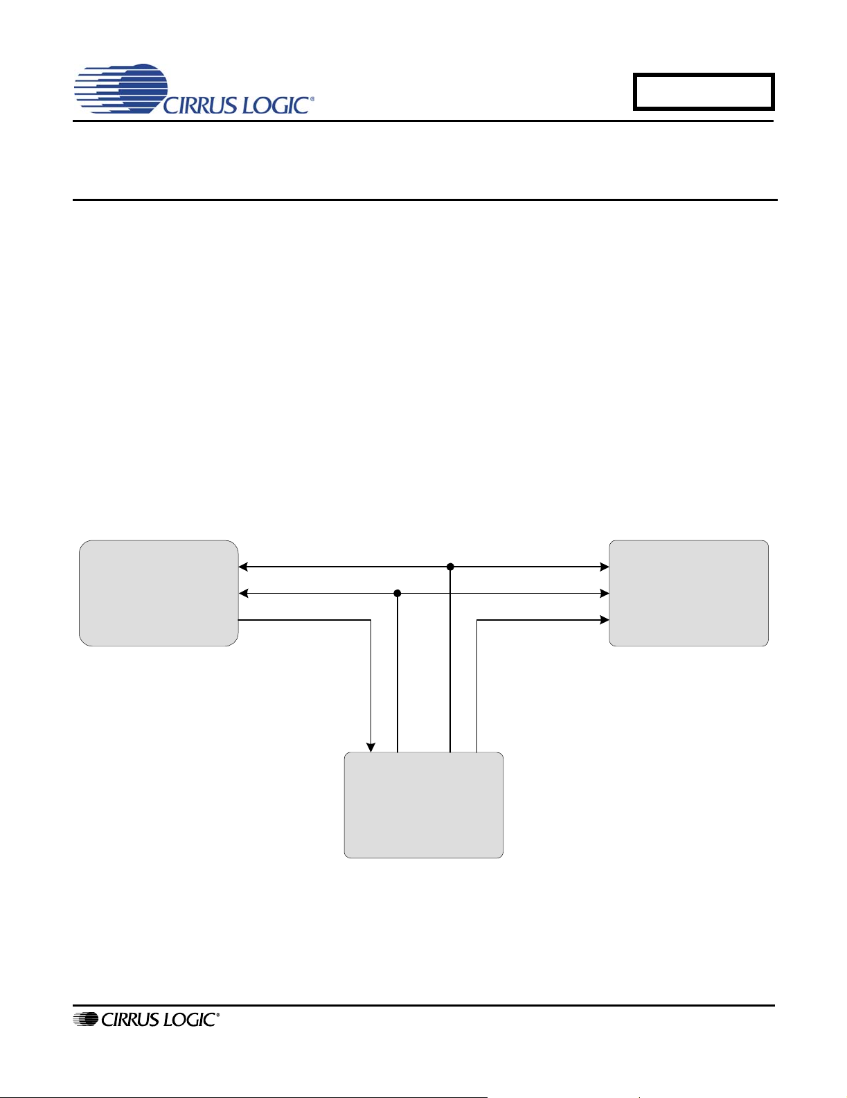
Transferring multiple channels of digital audio data within an audio product can be a challenge. The complexities
involving signal routing and providing a sufficient number of input/output ports on digita l-signal-processors and converters can be a daunting task. As a result, the industry has adopted a Time Division Multiplexed (TDM) interface
that allows multiple channels of data to be transmitted on a single data lin e. The TDM inte rface is by fa r the most
common mechanism used to transfer multiple channels of audio data betwe en devices withi n a system as shown in
Figure 1. The TDM interface has not been standardized and there can be variants between the TDM formats. For-
tunately the TDM ports in DSP devices are programmable and will support the multitude of options.
It is advantageous to limit the degrees of flexibility in a TDM interface for analog-to-digital converters, digital-to-an-
alog converters, multiple function audio CODECs and other high-performance mixed-signal products to avoid potential performance degradation due to clock interference. As a result, Cirrus Logic has chosen to standardize on a
TDM format for audio converter products and support a subset of the options that are available with DSP devices,
including the DSP products from Cirrus Logic. The goal of this document is to present an overview of the TDM interface and a discussion of the TDM format that is supported in Cirrus Logic audio converter products.
Multi-Channel
Analog-to-Digi tal Converter
Frame Sync
Serial Clock
Serial DataSerial Data
DSP
Figure 1. TDM System Block Diagram
Multi-Channel
Digital-to-Analog Conve rter
http://www.cirrus.com
Copyright © Cirrus Logic, Inc. 2006
(All Rights Reserved)
SEPTEMBER '06
AN301REV1
Page 2
AN301
1. TDM OVERVIEW
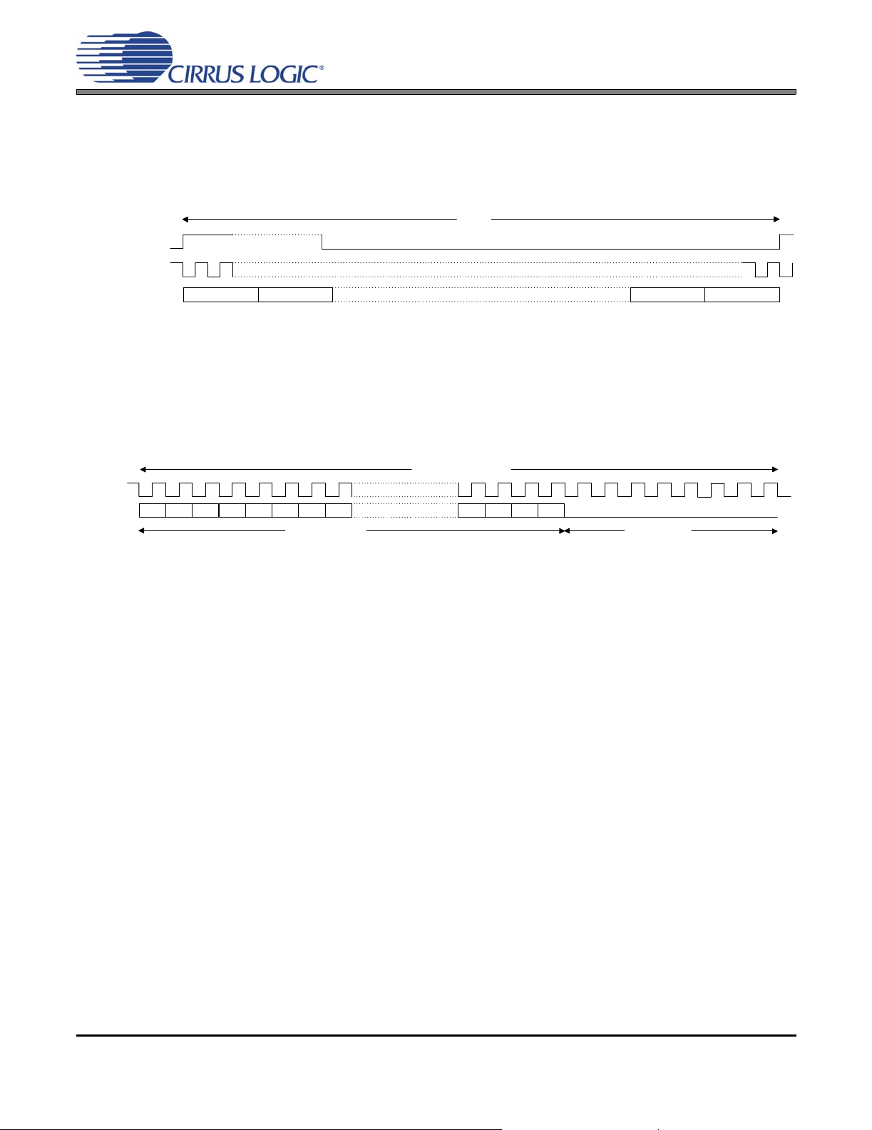
The TDM interface is similar to the 2-Channel Serial Audio Interface, discussed in Cirrus Applications Note AN282,
with the exception that more channels, typically 4, 6 or 8, are transmitted within a sample frame or sample period,
as shown in Figure 2. As with the 2-Channel Serial Audio Interface, the TDM interface is comprised of two control
clocks, a frame synchronization pulse (FSYNC) and serial clock (SCLK), and the serial audio data line (SDATA).
Frame
FSYNC
SCLK
SDATA
Channel 1
Channel 2
Figure 2. Generic TDM Interface
1.1 Channel Block
Each channel block is comprised of the audio data word followed by a sufficient number of zero data bits to
complete the N-bit channel block. The example shown in Figure 3 shows a 32-bit chan nel block with 24-bit
audio data. Notice that the audio word is typically transmitted with the Most Significant Bit (MSB) first. The
industry standard for representing Pulse-Coded-Modulation (PCM) audio data is a 16 to 32 bit word (16and 24-bit are the most common) coded in a two’s-complement format.
MSB
-1 -2
-4 -5
-3
24-Bit Audio Word
-7
-6
Figure 3. 32-Bit Channel Block
1.2 Frame Synchronization Pulse
The function of the FSYNC pulse is simply to identify the beginning of a frame. The beginning is always
indicated by the rising edge of the pulse, as shown in Figure 2. Another notable point is that the frame rate
is always at the audio sample rate, such as 44.1 kHz, 48 kHz, etc.
The majority of the TDM implementations only use the rising edge of FSYNC and ignore the falling edge.
However, device product documentation often implies that the width of the pu lse is important. There are two
common representations for the required width of the FSYNC pulse. The first is a frame synchronization
pulse where the width is equivalent to a channel block. The second is a pulse where the width is equivalent
to a single period of the serial clock. Unfortunately, the product documentation rarely supplies a sufficient
amount of information to determine if the falling edge is used. The safe approach is to follow the product
documentation and assume the falling edge is used or contact the manufacturer for clarification.
32-Bit Channel Block
+3
Channel N-1 Channel N
LSB
+1
+2
8-Bit Zero Pad
1.3 Channel Block Alignment with Frame Sync
There are two common options for the alignment of the first channel block and the rising edge of FSYNC.
The first is shown in Figure 2. where the beginning of the channel block aligns with the rising edge of the
FSYNC. In the second option, the channel block is delayed one per iod of the serial clock following the rising
edge of the FSYNC.
1.4 Serial Clock
The sole purpose of the serial clock is to shift the audio data into or out of the ser ial audio ports. The required
frequency for the serial clock is directly proportional to the system audio sample rate, the number of channel
blocks within a frame and the bit-wi dth of each channel block. As an example, an 8-channel frame with 32bit channel blocks operating at 48 kHz requires a 12.288 MHz serial clock.
2 AN301REV1
Page 3

AN301
2. CIRRUS LOGIC AUDIO CONVERTER TDM INTERFACE
All Cirrus Logic converter products are capable as operating as a slave to a systems clock, such as a DSP generated
serial clock and FSYNC. When operating in this mo de, the requir ed pulse width of the fr ame sync is extremely fle xible, as shown in Figure 4, where the minimum high time is one period of the serial clock and the minimum low time
is also one period of the serial clock. Many Cirrus Logic products also are capable of sourcing the systems clocks
or operating as a systems clock Master. When operated in this mode the du ty cycle of the FSYNC is 50% of the
frame period as shown in Figure 5.
Cirrus Logic has chosen to implement a serial port configuration where the channel block is delayed one period of
the serial clock following the rising edge of the FSYNC as shown in Figure 4 and Figure 5. Notice that the last bit of
the Channel N block is within the FSYNC pulse of the next frame.
Frame
FSYNC
SCLK
SDATA
FSYNC
SCLK
SDATA
Channel 1
Channel 1
2.1 Channel Block
The standard Cirrus Logic implementation for a data transmitter is a 32-bit channel block with 24-bit audio
data as previously discussed a nd show n in Figure 3. The standard implementation for a data receiver is a
32-bit channel block with 24-bit audio data as shown in Figure 6. Notice that the trailing 8-bit pad is not required to be zero since the receiver will ignore the trailing 8-bits.
A limited number of Cirrus Logic products support a 16-bit channel b lock for use with 16-bit da ta. Please be
aware that both the data transmitter and receiver must be configu red for a 16-bit ch annel block. Many DSP
devices also support a 24-bit channel block which is efficient for transmitting 24-bit audio d ata. Unfortunately, this requires serial clocks and data rates which are asynchronous to the conversion processes in mixedsignal products. This can degrade analog performance and, as a result, Cirrus Logic converte r products do
not support a 24-bit channel block.
Channel 2
Figure 4. Cirrus Logic TDM System Clock Slave Format
Frame
Figure 5. Cirrus Logic TDM System Clock Master Format
Channel N-1 Channel N
Channel NChannel N/2
32-Bit Channel Block
MSB
-2 -3
-1
-4 -5
24-Bit Audio Word
-7
-6
+2
+3
LSB
+1
8-Bit Pad
Figure 6. 32-Bit Receiver Channel Block
2.2 Exceptions to the Rule
Despite efforts to standardize on a TDM interface, there are occasionally situations that require deviation
from the standard, as well as legacy implementations that deviate from this format. An example is the
CS8421 Asynchronous Sample Rate Converter which can use the full 32-bit channel block for audio data.
Please refer to the product data sheet to confirm device operation.
AN301REV1 3
Page 4

3. REVISION HISTORY
Release Changes
Revision 1 Initial Release
AN301
Contacting Cirrus Logic Support
For all product questions and inquiries, contact a Cirrus Logic Sales Representative.
To find the one nearest you, go to www.cirrus.com.
IMPORTANT NOTICE
Cirrus Logic, Inc. and its subsidiaries ("Cirrus") believe that the information contained in this document is accurate and reliable. However, the information is subject
to change without not ice and is pr ovided "AS IS" witho ut warr anty of any kind (express or implied). Customers are advised to obtain the latest version of relevant
information to verify, before placing orders, that information being relied on is current and complete. All products are sold subject to the terms and conditions o f sale
supplied at the time of order acknowledgment, including those pertaining to warranty, indemnification, and limitation of liability. No responsibility is assumed by Cirrus
for the use of this information, including use of this information as the basis for manufacture or sale of any items, or for infringement of patents or other rights of third
parties. This document is the property of Cirrus and by furnishing this information, Cirrus grants no license, express or implied under any patents, mask work rights,
copyrights, trademarks, trade secrets or other inte llectual property rig hts. Cirrus owns the copyrights associated with the information contained herein and gives consent for copies to be made of the information only for use within your organization with respect to Cirrus integrated circuits or other products of Cirrus. This consent
does not extend to other copying such as copying for general distribution, advertising or promotional purposes, or for creating any work for resale.
CERTAIN APPLICATIONS USING SEMICONDUCTOR PRODUCTS MAY INVOLVE POTENTIAL RISKS OF DEATH, PERSONAL INJURY, OR SEVERE PROPERTY OR ENVIRONMENTAL DAMAGE (“CRITICAL APPLICATIONS”). CIRRUS PRODUCTS ARE NOT DESIGNED, AUTHORIZED OR WARRANTED FOR USE
IN AIRCRAFT SYSTEMS, MILITARY APPLICATIONS, PRODUCTS SURGICALLY IMPLANTED INTO THE BODY, AUTOMOTIVE SAFETY OR SECURITY DEVICES, LIFE SUPPORT PRODUCTS OR OTHER CRITICAL APPLICATIONS. INCLUSION OF CIRRUS PRODUCTS IN SUCH APPLICATIONS IS UNDERSTOOD TO BE FULLY AT THE CUSTOMER’S RISK AND CIRRUS DISCLAIMS AND MAKES NO WARRANTY, EXPRESS, STATUTORY OR IMPLIED,
INCLUDING THE IMPLIED WARRANTIES OF MERCHANTABILITY AND FITNESS FOR PARTICULAR PURPOSE, WITH REGARD TO ANY CIRRUS PRODUCT
THAT IS USED IN SUCH A MANNER. IF THE CUSTOMER OR CUSTOMER’S CUSTOMER USES OR PERMITS THE USE OF CIRRUS PRODUCTS IN CRITICAL
APPLICATIONS, CUSTOMER AGREES, BY SUCH USE, T O FULLY INDEMNIF Y CIRRUS, ITS OF FICE RS, DI RECTORS, EMPLOYEES, DISTRI BUTORS AND
OTHER AGENTS FROM ANY AND ALL LIABILITY, INCLUDING ATTORNEYS’ FEES AND COSTS, THAT MAY RESULT FROM OR ARISE IN CONNECTION
WITH THESE USES.
Cirrus Logic, Cirrus, and the Cirrus Logic logo designs are trademarks of Cirrus Logic, Inc. All other brand and product names in this document may be trademarks
or service marks of their respective owners.
4 AN301REV1
 Loading...