

Page 1
Application Note
USING THE CS5460A AUTO-BOOT MODE
AN225
1. Which EEPROMs Can Be Used?
Several industry-standard serial EEPROMs that
will successfully run auto-boot with the CS5460A
are listed below:
•Atmel
AT25010
AT25020
AT25040
• National Semiconductor
NM25C040M8
NM25020M8
•Xicor
X25040SI
These types of serial EEPROMs expect a specific
8-bit command word (00000011) in order to perform a memory download. The CS5460A has been
hardware programmed to transmit this 8-bit command word to the EEPROM at the beginning of the
auto-boot sequence.
1.1 Further Explanation of the Auto-Boot Sequence
The auto-boot sequence is terminated by writing a
‘1’ to the STOP bit in the CS5460A’s Control Register. This action is performed as the last command
in the EEPROM command sequence. At the completion of the write to the Control Register (provided STOP bit = “1”), SCLK stops, and CS
thereby reducing power consumed by the EEPROM. At completion of the Auto-Boot sequence,
the serial port will revert to functioning as a slavemode interface. Therefore, if desired, the
CS5460A registers can still be read by an external
device, such as a central office controller, connected to the meter assembly by a bus interface.
1.2 Sample Auto-Boot Sequence
The serial data for such a sample sequence is
shown below in single-byte hexidecimal notation:
rises,
40 00 00 61 ;In Configuration Register,
turn high-pass filters on, set
K=1.
44 7F C4 A9 ;Write value of 0x7FC4A9 to
Current Channel Gain Register.
46 7F B2 53 ;Write value of 0x7FB253 to
Voltage Channel DC Offset
Register.
4C 00 00 14 ;Set Pulse Rate Register to
0.625 Hz.
74 00 00 04 ;Unmask bit #2 (“LSD” bit in
the Mask Register).
E8 ;Start performing continuous
computation cycles.
78 00 01 40 ;Write STOP bit to Control
Register, to terminate autoboot initialization sequence,
andalsosettheEOUT
output to Mechanical Counter
Format.
When the CS5460A is commanded by the EEPROM to perform a certain operation, the operation will not be pre-maturely terminated by the
assertion of the Control Register’s STOP bit. In the
above example, the ‘Start Conversions’ command
(0xE8) is issued from the EEPROM, and therefore
the CS5460A will continue to perform continuous
A/D conversions even after the STOP bit is asserted.
1.3 How do I reset the CS5460A in Auto-Boot Mode during Brown-Out/Black-Out conditions?
The power line that is to be metered may enter a
black-out or brown-out condition at certain times,
due to problems at the power plant or other environmental conditions (ground fault, electrical
storms, etc.) In such conditions, it is important for
the meter assembly to accomplish a proper reset,
pulse
www.cirrus.com
CopyrightCirrus Logic, Inc. 2003
(All Rights Reserved)
FEB ‘03
AN225REV1
1
Page 2
AN225
so that it can continue normal metering operations
once the line power is restored. When the
CS5460A is controlled by a microcontroller, the microcontroller is typically programmed (by the user)
to handle these power-fail-reset situations. In the
case of auto-boot, the CS5460A may be expected
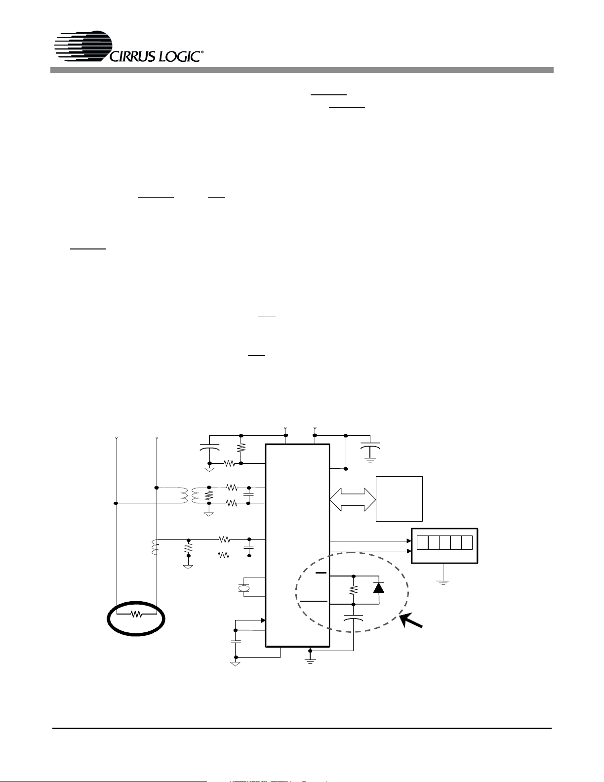
to reset itself (by re-executing the Auto-Boot sequence) whenever the line-power is restored. Figure 1 shows a reasonably reliable way to configure
the CS5460A’s RESET
and INT pins of the
CS5460A to restart the Auto-Boot sequence after
a brown-out or black-out condition. This configuration employs a diode, a resistor, and a capacitor on
the RESET
pininanattempttoallowtheCS5460A
to reboot after a sudden loss of power, followed by
a reinstatement of power.
Note that in the above auto-boot example code set
(see Section 1.2) the LSD bit is un-masked, in order to cause a high-to-low transition on the INT
pin
whenever the PFMON low-supply threshold is
reached on the PFMON pin. If a power supply loss
condition is sensed on PFMON, then the INT
pin is
asserted to low (because LSD is un-masked),
which allows the BAT85 diode to quickly drain the
charge on C
. But whenever the +5V power is
BOOT
restored, the resistor-capacitor network will force
RESET
the RESET
to recharge slowly. The slow rise-time on
pin can help to allow the oscillator circuitry and the CS5460A’s internal reference circuitry enough time to stabilize before the device
attempts to re-execute with the Auto-Boot sequence. This will allow the CS5460A to resume its
normal metering operations after power is restored. (User must provide suitable resistor divider
configuration on the PFMON pin, see Figure 1.)
Use of this configuration does not guarantee that
the CS5460A will reset properly, when exposed to
any sudden disturbance in power.
In addition to the configuration described above,
the designer should include sizeable commonmode capacitors to the VA+/VD+ pins (see
Figure 1). Such capacitance on the analog/digital
power supply pins will increase the amount of time
over which the CS5460A will remain operational
after power is lost, which therefore increases the
chances that the CS5460A will successfully re-execute a proper reboot upon restoration of power.
Suggested values are >47 µF (per pin) or >100 µF
(total).
N
LOAD
Figure 1. CS5460A Auto-Boot Configuration: Automatic Restart After Power Failure
L
T2
47 uF
AGND
T1
AGND
AG
+
ND
4.096 MHz
CRYSTAL
AGND
+5V
VA+ VD+
PFMON
VIN+
VIN-
CS5460A
IIN+
IIN-
XIN
XOUT
REFIN
REFOUT
VA- DGND
+5V
Mode
EOUT
EDIR
INT
RESET
DGND
10k
30uF
SPI
+
+
C
47 uF
BOOT
DGND
E2PROM
BAT85
00000
TOTALIZER
DGND
This resistor-capacitor- diode
configuration helps to ensure a
smooth power-down, as well as
a proper power-up/reset during
and after a power black-out or
brown-out event.
2
Page 3

AN225
Contacting Cirrus Logic Support
For all product questions and inquiries contact a Cirrus Logic Sales Representative.
To find one nearest you go to www.cirrus.com
IMPORTANT NOTICE
“Preliminary” product information describes products that are in production, but for which f ull char acterization data is not yet available. “Advance” product information describes products that are in devel opment and subject to development changes. Cirrus Logic, Inc. and its subsi diaries (“Cirrus”) believe that the information contained in this document is accurate and reli able. However, the information is subject to change without notice and is provided “AS IS” without warranty
of any kind (express or implied). Customers are advised to obtain the latest version of relevant information to verify, before placing orders, that information being
relied on is current and complete. All products are sold subject to the terms and conditions of sale supplied at the time of order acknowledgment, including those
pertaini ng to warranty, patent infringement, and limitation of liability. No r esponsibi lity is assumed by Cirrus for the use of thi s information, i ncluding use of this
informati on as the basis for manufacture or sale of any items, or for infri ngement of patents or other rights of thi rd parties. This document is the property of Cirrus
and by furnishing this information, Cirrus grants no license, express or implied under any patents, mask work rights, copyrights, trademarks, trade secrets or
other intellectual property rights. Cirrus owns the copyri ghts associated with the information contained herein and gi ves consent for copies to be made of the
informati on only for use within your organization with respect to Cirrus int egrated circuits or other parts of Cirrus. This consent does not extend to other copying
such as copying for general distribution, advertising or promotional pur poses, or for creating any work for resale.
An export permit needs to be obtained from the competent authorities of the Japanese Government if any of the products or technologi es describe d in thismaterial and controlled under the “Foreign Exchange and Forei gn Trade Law” is to be exported or taken out of Japan. An export l icense and/or quota needs to be
obtained from the competent authorities of the Chinese Government if any of the products or technologies described in this material is subject to the PRC Foreign
Trade Law and is to be exported or taken out of the PRC.
CERTAIN APPLICATIONS USING SEMICONDUCTOR PRODUCTS MAY INVOLVE POTENTIAL RISKS OF DEATH, PERSONAL INJURY, OR SEVERE
PROPERTY OR ENVIRONMENTAL DAMAGE (“CRITICAL APPLICATIONS”). CIRRUS PRODUCTS ARE NOT DESIGNED, AUTHORIZED, OR WARRANTED TO BE SUITABLE FOR USE IN LIFE-SUPPORT DEVICES OR SYSTEMS OR OTHER CRITICAL APPLICATIONS. INCLUSION OF CIRRUS PRODUCTS
IN SUCH APPLICATIONS IS UNDERSTOOD TO BE FULLY AT THE CUSTOMER'S RISK.
Cirrus Logic, Cirrus, and the Cirrus Logic l ogo designs are trademarks of Cirrus Logic, Inc. All other brand and product names in this document may be trademarks or service marks of their respecti ve owners. Microwire is a trademark of National Semiconductor Corporation.
3
Page 4

 Loading...