

Page 1
AN22
Application Note
OVERVIEW OF DIGITAL AUDIO INTERFACE
DATA STRUCTURES
Clif Sanchez & Roger Taylor
The following information is pro vided for convenience, but by no mean s con stitu tes the enti re sp ecification. Also included is information from the
IEC958 and the new AES3-199x a nd TC84 docu ments. The AES3-199x and TC84 documents have
not received approval as of the printing of this data
sheet. To guarantee conformance, a copy of the actual sp ecification should be obtained from the Audio Engineering Society or ANSI (ANSI
S4.40-1985) for the AES3 document, and the International Electrotechnical Commission for the
IEC958 docume nt.
The AES/EBU interface is a means for serially
communic ating dig ital audio da ta through a si ngle
transmission lin e. I t pro vides tw o cha nn els f or audio data, a me thod for commun icating control in formation, and some error detection capabilities.
Cirrus Logic, Inc.
Crystal Semiconductor Products Division
P.O. Box 17847, Austin, Texas 78760
(512) 445 7222 FAX: (512) 445 7581
http://www.crystal.com
The control information is transmitted as one bit
per sample and accumulates in a block structure.
The data is bipha s e encoded, which enables the receiver to extract a clock from the data. Coding violations, de fined as pream bles, are used to identify
sample and block boundaries.
Frames Sub-frames and Blocks
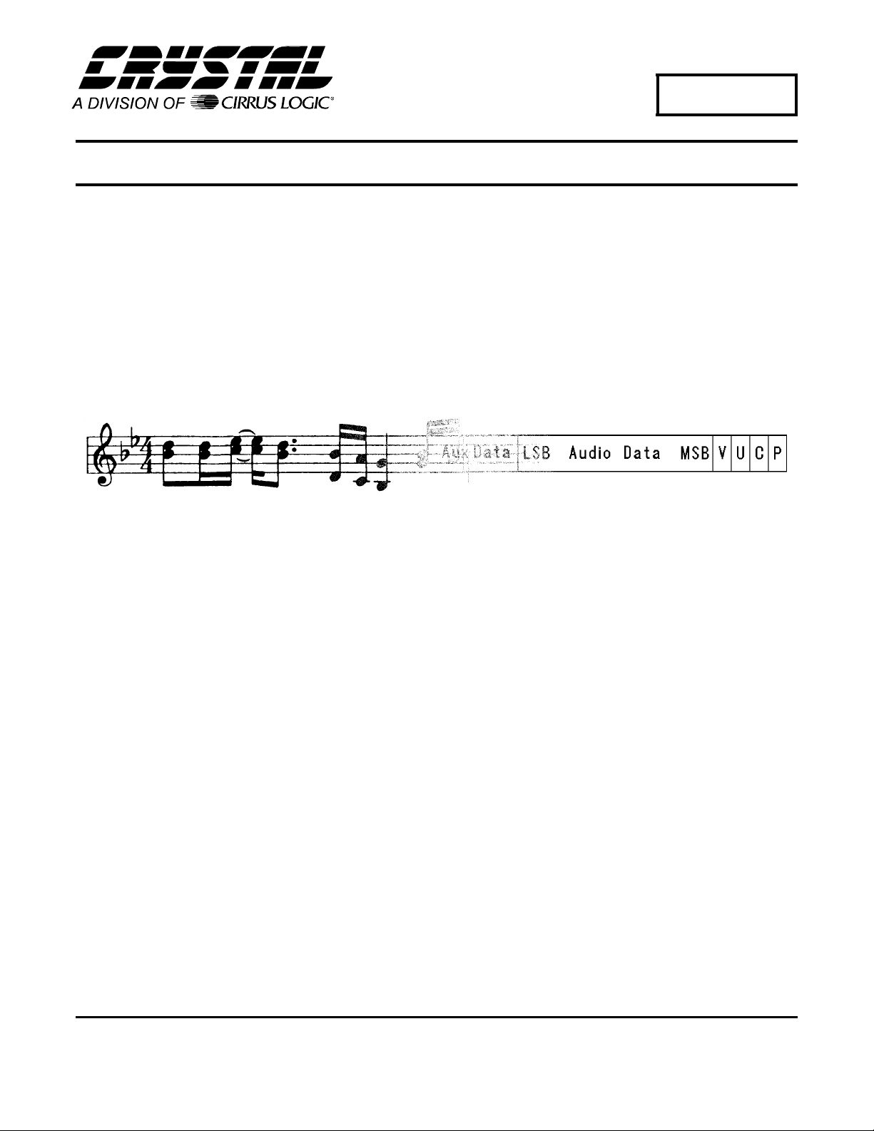
An audio sample i s place d in a stru ct ure kn own as
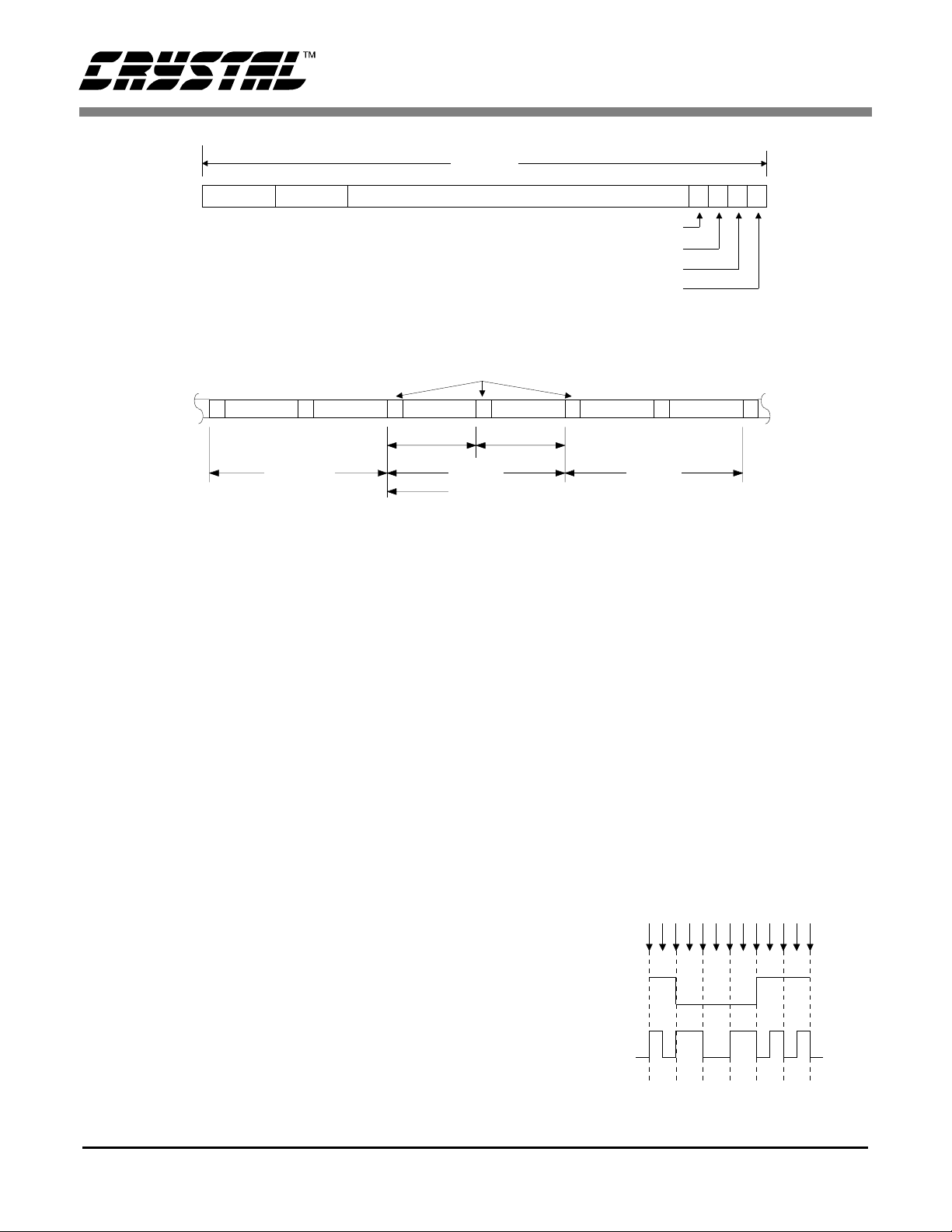
a sub-frame. The sub-frame, shown in Figure 1,
consists o f 4 bits of preamble, 4 bits of auxiliary
data, 20 bits of audio data, 3 bits called validity, user, and channel status, and a parity bit. The preamble contains biphase coding violations and
identifies th e star t of a sub-fram e. The audio sa mple word length can va ry up to 24 bits and is transmitted LSB fi rst. If th e wor d lengt h is grea ter th an
20 bits, the sample occupies both the audio and
Copyright Cirrus Logic, I nc. 1998
(All Rights Reserv ed)
AN22REV2
FEB ‘98
1
Page 2
AN22
bit
0347
Aux Data
Channel A
X
Y
8
LSB
Channel B
Figure 1. Sub-frame Format
Channel AZChannel B
Sub-frame Sub-frame
Figure 2. Frame/Block Format
auxiliary data fields. If it is 20 bits or less, the auxiliary field can b e used for other a pplica tions such
as voice. T he parity bit g enerates even pa rity and
can detect an odd number of transmi ssion errors in
the sub-frame. The validity bit, when low, indicates
the audio sample is fit for conversion to analog.
The user an d channel sta tus bits are se nt once per
sample and, when accumulated over a number of
samples, define a blo ck of da ta. The user bit ch annel is undefined and available to the user fo r any
purpose. The channel status bit conveys, over an
entire block, important information about the audio
data and t ransmissi on link. Eac h of the tw o audio
channels has its own channel status data with a
block structure that repeats every 192 samples.
As shown in Figure 2, two consecutive sub-fram e s
are defined as a f rame , cont aining channel s A and
B, and 192 frame s define a block. The preambles
that identify the start of a sub-frame a re different
for each of the two channels with another unique
one identify ing the beginning of a channel sta tus
block.
Sub-frame
Audio DataPreamble
Channel Status Data
Preambles
Y
Frame 0Frame 191
Start of Channel Status Block
Channel A
X Channel BY X
Validity
User Data
Parity Bit
Frame 1
27
MSB
28 29 30 31
VUCP
Modulation and Preambles
The data is t ransmitted w ith biphase-m ark encoding to minimize the DC component and to allow
clock recovery from the data. As illustrated in
Figure 3, the 1’s in the data have transitions in the
center, and the 0’s do not, after biphase-mark encoding. Also, the biphase-mark data switche s polarity at every data bit boundary. Since the value of
the data bit is determined by whether there is a transition in th e cen te r of th e bit , th e ac tu al po la rity of
the signal is irrelevant.
Each sub-frame starts with a preamble. This allows
a receiver to lock on to the data within one
sub-frame. The re are three defin ed pream bles: one
(2 times bit rate)
Biphase-Mark
Clock
100011
Data
Data
101100110101
Figure 3. Biphase-Mark Encoding
2 AN22REV2
Page 3
AN22
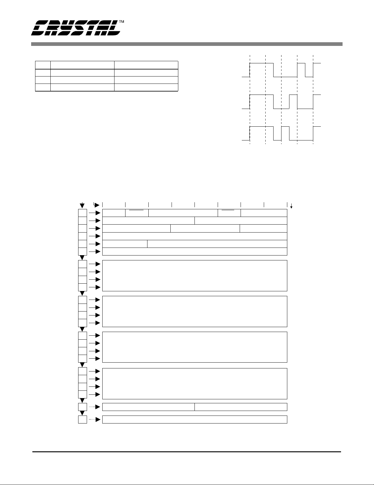
Biphase Patterns Channel
X 11100010 or 00011101 Ch. A
Y 11100100 or 00011011 Ch. B
Z 11101000 or 00010111 Ch. A & C.S. Block Start
Table 1. Preambles
for each chan nel an d one to ind icat e the b eginn ing
of a channel status block (which is also channelA).
To distinguish the preambles from arbitrary data
patterns, the preambles contai n two biphase-mark
violations. Bi pha se-mark data is requir ed to transition at every bit period, but each preamble violates
that requirement twice. In Figure 3 each bit boundary, indic ated by the d ashed l ines, c ontains a tran sition in the bipha se da ta. Each preamble shown in
byte/bit
0
1
2
3
4
5
0123
PRO=1
Reference
Audio
Channel Mode
AUX Use Word Length
Emphasis
11100010
Preamble X
11100100
Preamble Y
11101000
Preamble Z
Figure 4. Preamble Forms
Figure 4 has two bit boundaries with no transition,
which enables the receiver to recognize the data as
a preamble.
block
bit
7
7
15
23
31
39
47
Reserved
Reserved
4
Reserved
56
Lock
User Bit Management
Fs
Reserved
6
7
8
9
10
11
12
13
14
15
16
17
18
19
20
21
22
23
Alphanumeric channel origin data
Alphanu m er i c chan nel destina tion data
Local sample address code
(32-bit bina ry)
Time of day code
(32-bit binary)
Reserved
Cyclic redundancy check character
Reliability flags
Figure 5. Professional Channel Status Block Structure
55
87
119
151
183
191
AN22REV2 3
Page 4

AN22
Table 1 lists the preamble biphase-mark data patterns and what each designates. Since biphase-mark encoding is not polarity conscious,
both phases are shown in the table . Preamb les "X"
and "Y" indicate a sub-frame containing
channels A and B respectively. Preamble "Z" replaces preamb le "X" once eve ry 192 frames to indicate the sta rt of a cha nnel status block.
There are two channel status blocks, one for
channel A and one for channel B . Since there a re
192 frame s in a bl ock, ea ch c hanne l h as a chann el
status block 192 bits long. These 192 channel status bits in a block can be arranged as 24 bytes. The
blocks have one of two formats, professional or
consumer. The first bi t of the channe l status bl ock
defines the for ma t wit h 0 indic a ting c onsu mer and
1 indicating pro fessi ona l .
Channel Status Block - Professional Format
Setting the first bit of channel status high designates the professional or broadcast format. The
channel stat us block structu re for the profe ssional
format is illustr ated i n Fig ure 5 and shows b it 0 of
byte 0, PRO, to contain a one. Tables 2 and 3 list
the bits in each byt e and th eir mea ning. T he area s
designated "reserved" in the fi gures and tables, a re
currently not spec ified and must be set to 0 when
transmitting. Most of the professi onal format data
was obtained fro m the AES3-1985 doc ument, and
information from AES3-199x. Since the AES specification is currently being updated, the accuracy of
this data is not guaranteed.
BYTE 0
bit 0 PRO = 1
0 Consumer use of channel status block
1 Professional use of channel status block
bit 1 Audio
0Normal Audio
1 Non-Audio
bits 2 3 4 Encoded audio signal emphasis
0 0 0 Emphasis not indicated. Receiver
defaults to no emphasis with manual
override enabled
1 0 0 None. Rec. manual override disabled
1 1 0 50/15 µS. Rec. manual override disabled
1 1 1 CCITT J.17 . Rec. man. override disabled
X X X All other states of bits 2-4 are reserved
bit 5 Lock: Source Sample Frequency
0 Locked - default
1 Unlocked
bits 6 7 Fs: Sample Frequency
0 0 Not indicated. Receiver default to 48 kHz
and manual override or auto set enabled
0 1 48 kHz. Man. override or auto disabled
1 0 44.1 kHz. Man. override or auto disabled
1 1 32 kHz. Man. override or auto disabled
BYTE 1
bits0123Channel Mode
0000Mode not indicated. Receiver default to
2-channel mode. Manual override enabled
0001Two-channels. Man. override disabled
0 0 1 0 Single channel. Man. override disabled
0011Primary/Secondary (Ch. A is primary)
Manual override disabled
0100Stereophonic. (Ch. A is left)
Manual override disabled.
0101Reserved for user defined application
0110Reserved for user defined application
1111Vector to byte 3. Reserved
XXXXAll other states of bits 0-3 are reserved.
bits4567User bits management
0000Default, no user info indicated
0001192 bit block structure
Preamble ‘Z’ starts block
0010Reserved
0011User defined application
XXXXAll other states of bits 4-7 are reserved.
Table 2. Professional Channel Status bytes 0-1.
4 AN22REV2
Page 5

AN22
BYTE 2
bits 0 1 2 AUX: Use of auxiliary sample bits
0 0 0 Not defined. Maximum audio word length
is 20 bits
0 0 1 Used for main audio. Maximum audio
word length is 24 bits
0 1 0 Single coordination signal. Max. audio
word length is 20 bits
0 1 1 User defined application
X X X All other states of bits 4-7 are reserved.
bits
34 5
0 0 0 Not Indicated Not Indicated
0 0 1 23 bits 19 bits
0 1 0 22 bits 18 bits
0 1 1 20 bits 16 bits
1 0 1 24 bits 20 bits
X X X All other states of bits 3-5 are reserved
bits 6 7
XX Reserved
bits 0-7 Vectored target byte
XXXXXX Reserved
bits
01
0 0 Not reference signal (defaul t)
0 1 Grade 1 reference signal
1 0 Grade 2 reference signal
11 Reserved
bits 2 7
XXXXXX Reserved
bits 0-7
XXXXXX Reserved
Source word length
Max. audio based on bits 0-2 above
Max audio 24 bits Max audio 20 bits
(default)
BYTE 3
BYTE 4
Digital audio reference signal per
AES11-1990
BYTE 5
BYTE 6-9
Alphanumeric channel origin data
7-bit ISO 646 (ASCII) data with odd parity bit. First character
in message is byte 6. LSB’s are transmitted first.
BYTE 10-13
Alphanumeric channel destination data
7-bit ISO 646 (ASCII) data with odd parity bit. First character
in message is byte 10. LSB’s are transmitted first.
BYTE 14-17
Local sample address code (32-bit binary)
Value is of first sample of current block.
LSBs are transmitted first.
BYTE 18-21
Time-of-day sample address code (32-bit binary)
Value is of first sample of current block.
LSBs are transmitted first.
BYTE 22
bits0123
XXX Reserved
bit 4 Channel status bytes 0 to 5
0 Reliable
1 Unreliable
bit 5 Channel status bytes 6 to 13
0
1
bit 6 Channel status bytes 14-17
0
1
bit 7 Channel status bytes 18 to 21
0 Reliable
1 Unreliable
CRCC: Cyclic redundancy check character
CRCC for channel status data block that uses bytes 0 to22
inclusive. Generating polynomial is
with an initial state of all ones
Reliable
Unreliable
Reliable
Unreliable
BYTE 23
G(x) = X8 + X4 + X3 + X2 + 1
Table 3. Professional Channel Status Bytes 2-23.
AN22REV2 5
Page 6

AN22
Channel Status Block - Consumer Format
Setting the first bit of channel status low designates
the consumer format. The channel status block
structure for the consumer format is illustra ted in
Figure 6 with the bit descriptions in Tables 4 and 5.
All areas listed as "rese rved" m ust be tr ansmitte d as
a 0. The data for this format was obtained from the
EIAJ CP-340 an d the IE C958 with some inf ormation from TC84 which is a proposed amendment to
IEC958 and has not received approval yet. As with
the professional format, since this format is currently changing, the accuracy of the data listed cannot be guarantee d.
byte/bit
01234567
0
1
2
3
PRO=0 Audio
Source Num. Channel Num.
Copy
Category Code
Fs
In the co nsume r form at, bit 0 m ust b e 0. If bit 1 i s
set to 1 defining the data as non-audio, then bits 3-5
are redefined (see Table 4, byte 0). Bits 6 and 7 of
byte 0 define the mode, and only one mode is presently define d, mode = 00. This mode defines the
next three bytes as listed in Figure 6. Most of byte 1
defines the ca tegory code. The first 3 to 5 bits de fine the general category. Under the laser-optical
category is compact disk (cat. code 1000000). This
format defines some of the Uchannel bits and the
CD subcode port. More information can be obtained from the CP-340 or IEC958 documents.
block
bit
Emphasis Mode
Clock Acc.
Reserved
L
7
15
23
31
4
5
6
7
8
9
10
11
12
13
14
15
16
17
18
19
20
21
22
23
39
Reserved
191
Figure 6. Consumer Channel Status Block Structure
6 AN22REV2
Page 7

AN22
BYTE 0
bit 0 PRO = 0 (consumer)
0 Consumer use of channel status block
1 Professional use of channel status block
bit 1 Audio
0
1
bits 2 Copy / Copyright
0
1
bits 3 4 5 Pre-emphasis - if bit 1 is 0 (dig. audio)
0 0 0 None - 2 channel audio
1
0
0
1
1
1
X
X
bits 3 4 5 if bit 1 is 1 (non-audio)
0 0 0 Digital data
X X X All other states of bits 3-5 are reserved
bits 6 6 Mode
0 0 Mode 0 (defines bytes 1-3)
X X All other states of bits 6-7 are reserved
bits3456Broadcast reception of digital audio
* 0000Japan
* 0011United States
* 1000Europe
* 0001Electronic software delivery
XXXXAll other states are reserved
bits3456Laser Optical
0000CD - compatible with IEC-908
* 1000CD - not comp. with IEC-908
XXXXAll other states are reserved
Digital Audio
Non-Audio
Copy inhibited / copyright asserted
Copy permitted / copyright not asserted
0
50/15 µs - 2 channel audio
0
Reserved - 2 channel audio
0
Reserved - 2 channel audio
1
Reserved - 4 channel audio
BYTE 1 - Category Code 001
BYTE 1 - Category Code 100
(magneto-optical)
BYTE 1
bits 0 1 2 3 4 5 6 Category Code
0000000General
* 0 0 1 Experimental
X X X Reserved
* 0001XXXSolid state memory
* 0 0 1 X X X X Broadcast recep. of digital audio
0 1 0 X X X X Digital/digital converters
* 0 1 1 0 0 X X A/D converters w/o copyright
* 1 X X A/D converters w/ copyright
(using Copy and L bits)
* 0 1 1 1 X X X Broadcast recep. of digital audio
1 0 0 X X X X Laser-optical
* 1 0 1 X X X X Musical Instruments, mics, etc.
1 1 0 X X X X Magnetic tape or disk
111XXXXReserved
bit 7 L: Generation Status.
Only category codes:001XXXX,
0111XXX,100XXXX
* 0 Original/Commercially pre-recorded data
* 1 No indication or 1st generation or higher
All other category codes
* 0 No indication or 1st generation or higher
* 1 Original/Commercially pre-recorded data
The subgroups under the category code groups listed above
are described in tables below. Those not listed are reserved.
The Copy and L bits form a copy protection scheme for
original works. Further explanations can be found in the
proposed amendment (TC84) to IEC-958.
BYTE 1 - Category Code 010
bits3456Digital/digital conv. & signal processing
0000PCM encoder/decoder
* 0010Digital sound sampler
* 0100Digital signal mixer
* 1100Sample-rate converter
XXXXAll other states are reserved
Table 4. Consumer Channel Status Bytes 0 and 1.
Currently the standards committees are trying to
define a m inimum i mple mentati on a s well a s leve ls
of implement at ion of channel status data.
A scheme for providing copy protection is also currently being developed. It includes knowing the
category code and then utilizing the Copy and L
bits to determine if a copy should be allowed. Dig-
ital processing of data should pass through the copy
and L bits as def ined by their particular category
code. If mixing inputs, the highe st level of pr otec tion of any one of the sources should be passed
through. If t he copy bit indi cates no copy pr otection (copy = 1), then m u ltipl e co pie s can be mad e.
If recording audio data to tape or disk, and any
AN22REV2 7
Page 8

AN22
source has copy prote ction asserte d, then the L bit
must be used to determ in e wheth er the dat a can be
recorded .
The L bit determines whether the source is an original (or pr erecorded) work, or is a copy of a n original work (first generation or higher). The actual
BYTE 1 - Category Code 101
bits3456Musical Instruments, mics, etc.
* 0000Synthesizer
* 1000Microphone
XXXXAll other states are reserved
BYTE 2
bits0123Source Number
0000Unspecified
10001
01002
11003
00104 to
011114 (binary - 0 is LSB, 3 is MSB)
111115
bit 4567Channel Number
0000Unspecified
1000A (Left in 2 channel format)
0100B (Right in 2 channel format)
1100C to
0111N (binary - 4 is LSB, 7 is MSB)
1111O
meaning of the L bit can only be determined by
looking at the category code sin ce certain category
codes reverse the meaning.
If the category code is CD (1000000) and the copy
bit alternat es at a 4 t o 10Hz ra te, the CD is a copy
of an original work that has copy protection asserted and no recording is permitted.
BYTE 1 - Category Code 110
bits3456Magnetic tape or disk
0000DAT
* 1000Digital audio sound VCR
XXXXAll other states are reserved
BYTE 3
bits0123Fs: Sample Frequency
000044.1 kHz
010048 kHzr
110032 kHz
1100Sample-rate converter
XXXXAll other states are reserved
bits 4 5 Clock Accuracy
00 Level II, ±1000 ppm (default)
0 1 Level III, variable pitch
10 Level I, ±50 ppm - high accuracy
11 Reserved
bits 6 7
XX Reserved
BYTE 4 - 23
Reserved
* Data from draft of IEC 958 proposed amendment (fr om TC84). Has not recieved approval yet.
Table 5. Consumer Channel Status Bytes 1-23
8 AN22REV2
Page 9

• Notes •
Page 10

 Loading...